EP3173491A1 - A reaction tank and continuous sugar dissolving apparatus and method - Google Patents
A reaction tank and continuous sugar dissolving apparatus and method Download PDFInfo
- Publication number
- EP3173491A1 EP3173491A1 EP16196495.2A EP16196495A EP3173491A1 EP 3173491 A1 EP3173491 A1 EP 3173491A1 EP 16196495 A EP16196495 A EP 16196495A EP 3173491 A1 EP3173491 A1 EP 3173491A1
- Authority
- EP
- European Patent Office
- Prior art keywords
- reaction tank
- syrup
- inlet
- mesh plate
- sugar
- Prior art date
- Legal status (The legal status is an assumption and is not a legal conclusion. Google has not performed a legal analysis and makes no representation as to the accuracy of the status listed.)
- Withdrawn
Links
Images

Classifications
-
- A—HUMAN NECESSITIES
- A23—FOODS OR FOODSTUFFS; TREATMENT THEREOF, NOT COVERED BY OTHER CLASSES
- A23L—FOODS, FOODSTUFFS OR NON-ALCOHOLIC BEVERAGES, NOT OTHERWISE PROVIDED FOR; PREPARATION OR TREATMENT THEREOF
- A23L5/00—Preparation or treatment of foods or foodstuffs, in general; Food or foodstuffs obtained thereby; Materials therefor
- A23L5/20—Removal of unwanted matter, e.g. deodorisation or detoxification
- A23L5/27—Removal of unwanted matter, e.g. deodorisation or detoxification by chemical treatment, by adsorption or by absorption
-
- A—HUMAN NECESSITIES
- A23—FOODS OR FOODSTUFFS; TREATMENT THEREOF, NOT COVERED BY OTHER CLASSES
- A23L—FOODS, FOODSTUFFS OR NON-ALCOHOLIC BEVERAGES, NOT OTHERWISE PROVIDED FOR; PREPARATION OR TREATMENT THEREOF
- A23L5/00—Preparation or treatment of foods or foodstuffs, in general; Food or foodstuffs obtained thereby; Materials therefor
- A23L5/40—Colouring or decolouring of foods
-
- B—PERFORMING OPERATIONS; TRANSPORTING
- B01—PHYSICAL OR CHEMICAL PROCESSES OR APPARATUS IN GENERAL
- B01D—SEPARATION
- B01D15/00—Separating processes involving the treatment of liquids with solid sorbents; Apparatus therefor
-
- B—PERFORMING OPERATIONS; TRANSPORTING
- B01—PHYSICAL OR CHEMICAL PROCESSES OR APPARATUS IN GENERAL
- B01D—SEPARATION
- B01D15/00—Separating processes involving the treatment of liquids with solid sorbents; Apparatus therefor
- B01D15/08—Selective adsorption, e.g. chromatography
- B01D15/10—Selective adsorption, e.g. chromatography characterised by constructional or operational features
- B01D15/22—Selective adsorption, e.g. chromatography characterised by constructional or operational features relating to the construction of the column
-
- C—CHEMISTRY; METALLURGY
- C13—SUGAR INDUSTRY
- C13B—PRODUCTION OF SUCROSE; APPARATUS SPECIALLY ADAPTED THEREFOR
- C13B20/00—Purification of sugar juices
- C13B20/12—Purification of sugar juices using adsorption agents, e.g. active carbon
-
- C—CHEMISTRY; METALLURGY
- C13—SUGAR INDUSTRY
- C13K—SACCHARIDES OBTAINED FROM NATURAL SOURCES OR BY HYDROLYSIS OF NATURALLY OCCURRING DISACCHARIDES, OLIGOSACCHARIDES OR POLYSACCHARIDES
- C13K1/00—Glucose; Glucose-containing syrups
-
- C—CHEMISTRY; METALLURGY
- C13—SUGAR INDUSTRY
- C13K—SACCHARIDES OBTAINED FROM NATURAL SOURCES OR BY HYDROLYSIS OF NATURALLY OCCURRING DISACCHARIDES, OLIGOSACCHARIDES OR POLYSACCHARIDES
- C13K1/00—Glucose; Glucose-containing syrups
- C13K1/06—Glucose; Glucose-containing syrups obtained by saccharification of starch or raw materials containing starch
- C13K1/08—Purifying
Definitions
- the present invention generally relates to sugar treatment systems, and in particular to continuous sugar dissolving systems and reaction tanks used in sugar treatment systems.
- Sugar is a core ingredient in many foods and drinks. Sugar is often dissolved to a simple syrup, and the simple syrup is an essential part of the production of a variety of products such as still drinks, confectionery, jam and carbonated soft drinks. Sugar can be added and dissolved in batches, or automatically in a continuous sugar dissolving system.
- the process of dissolving sugar often involves a step to decolor a dissolved sugar syrup and/or remove impurities from the syrup before using the syrup in food or drink products.
- adsorbents having strong adsorption capacity such as activated carbon
- syrup is passed through a reaction tank wherein it is contacted with an adsorbent such as activated carbon.
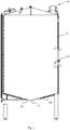
- Fig. 1 shows a prior art reaction tank 100.
- the reaction tank 100 comprises a syrup inlet 110, an adsorbent inlet 120 and an outlet 130.
- the syrup inlet 110 is arranged at a bottom 140 of the tank 100 and is used for syrup to be pumped into the reaction tank 100.
- the adsorbent inlet 120 may also be arranged at the bottom 140 and is used for adsorbent to be fed into the reaction tank 100.
- Processed syrup exits the reaction tank at the outlet 130 which is arranged at an upper sidewall 150 of the tank 100.
- syrup and adsorbent are fed into the reaction tank 100 from the syrup inlet 110 and the adsorbent inlet 120 respectively by a pump.
- the syrup and the adsorbent interact with each other in the reaction tank 100 so that the adsorbent removes coloring matter and impurities from the syrup.
- the processed syrup exits the tank through the outlet 130 at the upper sidewall of the tank 100.
- reaction tank has a drawback in that when pumping syrup into the reaction tank 100 from the syrup inlet, the syrup may rise straight up to the outlet 130 at the upper sidewall of the reaction tank 100 along with the inlet pressure head. As such, reaction time of the syrup entering the reaction tank cannot be adequately controlled and guaranteed, and thus effective treatment cannot be guaranteed.
- the reaction tank comprises a syrup inlet arranged at a bottom of the reaction tank, an adsorbent inlet arranged at the bottom of the reaction tank, a syrup outlet arranged at an upper sidewall of the reaction tank, and further comprises a mesh plate arranged within the reaction tank and at least above the syrup inlet.
- the syrup entering the reaction tank will first hit the mesh plate and pass through holes in the plate. Accordingly, the syrup will not go straight up with the inlet pressure head, such that the first syrup into the reaction tank is the first syrup out of the reaction tank.
- the reaction time of the syrup and the adsorbent can be better controlled. Thus, coloring matter and/or impurities in the syrup can be removed more sufficiently.
- the present invention also provides a method for manufacturing a reaction tank.
- the method comprises arranging a syrup inlet at a bottom of the reaction tank, arranging an adsorbent inlet at the bottom of the reaction tank, arranging a syrup outlet at an upper sidewall of the reaction tank, and arranging a mesh plate within the reaction tank and above the syrup inlet.
- a continuous sugar dissolving apparatus may comprise the reaction tank according to the present invention.
- the continuous sugar dissolving apparatus may include a dissolving tank for dissolving sugar in water to produce sugar syrup, and means to pass the sugar syrup through the reaction tank of the present invention, and the reaction tank of the present invention.
- the present invention further provides a method of treating sugar syrup, comprising flowing the sugar syrup through an inlet arranged at a bottom of a reaction tank; flowing an adsorbent through an inlet arranged at the bottom of the reaction tank, and draining the sugar syrup from the reaction tank via an outlet at an upper region of the reaction tank, wherein the adsorbent reacts with the sugar syrup in the reaction tank for removing color and/or impurities from the syrup, and wherein the sugar syrup enters the reaction tank below a mesh plate arranged within the reaction tank and above the syrup inlet, and passes through the mesh plate before reaching the outlet at the upper region of the reaction tank.
- the method of the present invention may be part of a continuous sugar dissolving method.
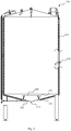
- the reaction tank 200 comprises a syrup inlet 210, an adsorbent inlet 220 and an outlet 230.
- the syrup inlet 210 is arranged at a bottom 240 of the tank 200 and is used for syrup to be supplied into the reaction tank 200, e.g. by pumping.
- the adsorbent inlet 220 is also arranged at the bottom 250 and is used for adsorbent to be fed into the reaction tank 200, e.g., by pumping.
- the outlet 230 is disposed at an upper sidewall 250 of the tank 200 and processed syrup exits the reaction tank through the outlet 230.
- the reaction tank 200 further comprises a mesh plate 260 which is mounted within the reaction tank 200 and arranged at least above the syrup inlet 210.
- the mesh plate is mounted above both the syrup inlet 210 and adsorbent inlet 220.
- the mesh plate can be any suitable material, but preferably is of the same material as the interior of the reaction tank, such as stainless steel.
- the mesh plate is preferably mounted at a sufficient distance from the syrup inlet 210 so as to facilitate the syrup to enter into the reaction tank while also reducing or removing the inlet pressure head.
- the distance between the mesh plate 260 and the syrup inlet 210 may be 200mm-400mm.
- the mesh plate is mounted at the inner side of the bottom 240 by one or more supporting members 270.
- the connection between the mesh plate and the supporting members, and the connection between the supporting members and the bottom of the tank can be bolt fastening, welding or other appropriate connection types.
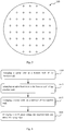
- Fig. 3 shows an exemplary embodiment of a mesh plate 260.
- the mesh plate 260 comprises a plurality of through holes therein which syrup may pass through.
- the through holes may be from 2mm-6mm in diameter.
- the mesh plate 260 shown in Fig. 3 is circular, the mesh plate also can be any other appropriate shape such as rectangular, triangular, polygonal, etc..
- the present invention also provides a method for manufacture the reaction tank.
- Fig. 4 shows a flow chart of manufacturing the reaction tank of present invention according to an explanatory embodiment.
- the method comprises the following steps: In step 410, arranging a syrup inlet at a bottom of the reaction tank; in step 420, arranging an adsorbent inlet at the bottom of the reaction tank; in step 430, arranging a syrup outlet at an upper sidewall of the reaction tank; and in step 440, arranging a mesh plate within the reaction tank and above the syrup inlet.
- Fig. 5 shows an exemplary embodiment of a method of treating sugar using the reaction tank of the present invention.
- the reaction tank may be part of a continuous dissolving apparatus, wherein the reaction tank receives dissolved sugar syrup from a dissolving tank.
- the method of treating sugar syrup comprises flowing the sugar syrup through an inlet arranged at a bottom of the reaction tank of the present invention in Step S510; flowing an adsorbent through an inlet arranged at the bottom of the reaction tank in Step S520, and draining the sugar syrup from the reaction tank via an outlet at an upper region of the reaction tank in Step S530, wherein the adsorbent reacts with the sugar syrup in the reaction tank for removing color and/or impurities from the syrup, and wherein the sugar syrup enters the reaction tank below a mesh plate arranged within the reaction tank and above the syrup inlet, and passes through the mesh plate before reaching the outlet at the upper region of the reaction tank.
- the adsorbent may also enter the reaction tank below the mesh plate arranged within the reaction tank.
Landscapes
- Chemical & Material Sciences (AREA)
- Life Sciences & Earth Sciences (AREA)
- Health & Medical Sciences (AREA)
- Organic Chemistry (AREA)
- Biochemistry (AREA)
- General Health & Medical Sciences (AREA)
- Emergency Medicine (AREA)
- Analytical Chemistry (AREA)
- Chemical Kinetics & Catalysis (AREA)
- Nutrition Science (AREA)
- Engineering & Computer Science (AREA)
- Food Science & Technology (AREA)
- Polymers & Plastics (AREA)
- Jellies, Jams, And Syrups (AREA)
Abstract
Description
- The present invention generally relates to sugar treatment systems, and in particular to continuous sugar dissolving systems and reaction tanks used in sugar treatment systems.
- Sugar is a core ingredient in many foods and drinks. Sugar is often dissolved to a simple syrup, and the simple syrup is an essential part of the production of a variety of products such as still drinks, confectionery, jam and carbonated soft drinks. Sugar can be added and dissolved in batches, or automatically in a continuous sugar dissolving system.
- The process of dissolving sugar often involves a step to decolor a dissolved sugar syrup and/or remove impurities from the syrup before using the syrup in food or drink products. In a decoloring step and/or step to remove impurities, adsorbents having strong adsorption capacity, such as activated carbon, are commonly used to remove coloring matter and impurities from the syrup. Often, syrup is passed through a reaction tank wherein it is contacted with an adsorbent such as activated carbon. For example,
Fig. 1 shows a priorart reaction tank 100. Thereaction tank 100 comprises asyrup inlet 110, anadsorbent inlet 120 and anoutlet 130. Thesyrup inlet 110 is arranged at abottom 140 of thetank 100 and is used for syrup to be pumped into thereaction tank 100. Theadsorbent inlet 120 may also be arranged at thebottom 140 and is used for adsorbent to be fed into thereaction tank 100. Processed syrup exits the reaction tank at theoutlet 130 which is arranged at anupper sidewall 150 of thetank 100. - In the reaction tank as shown in
Fig. 1 , syrup and adsorbent are fed into thereaction tank 100 from thesyrup inlet 110 and theadsorbent inlet 120 respectively by a pump. The syrup and the adsorbent interact with each other in thereaction tank 100 so that the adsorbent removes coloring matter and impurities from the syrup. With the liquid level of syrup in the reaction tank rising gradually in the tank, the processed syrup exits the tank through theoutlet 130 at the upper sidewall of thetank 100. - It has been discovered that the prior art reaction tank has a drawback in that when pumping syrup into the
reaction tank 100 from the syrup inlet, the syrup may rise straight up to theoutlet 130 at the upper sidewall of thereaction tank 100 along with the inlet pressure head. As such, reaction time of the syrup entering the reaction tank cannot be adequately controlled and guaranteed, and thus effective treatment cannot be guaranteed. - Therefore, there is a need to provide an improved reaction tank to overcome the shortcomings in the existing reaction tank.
- To overcome the shortcomings of existing reaction tank, the present invention provides an improved reaction tank. The reaction tank comprises a syrup inlet arranged at a bottom of the reaction tank, an adsorbent inlet arranged at the bottom of the reaction tank, a syrup outlet arranged at an upper sidewall of the reaction tank, and further comprises a mesh plate arranged within the reaction tank and at least above the syrup inlet.
- By arranging a mesh plate above the syrup inlet, the syrup entering the reaction tank will first hit the mesh plate and pass through holes in the plate. Accordingly, the syrup will not go straight up with the inlet pressure head, such that the first syrup into the reaction tank is the first syrup out of the reaction tank. Thus, the reaction time of the syrup and the adsorbent (such as activated carbon) can be better controlled. Thus, coloring matter and/or impurities in the syrup can be removed more sufficiently.
- The present invention also provides a method for manufacturing a reaction tank. The method comprises arranging a syrup inlet at a bottom of the reaction tank, arranging an adsorbent inlet at the bottom of the reaction tank, arranging a syrup outlet at an upper sidewall of the reaction tank, and arranging a mesh plate within the reaction tank and above the syrup inlet.
- In an aspect, a continuous sugar dissolving apparatus may comprise the reaction tank according to the present invention. The continuous sugar dissolving apparatus may include a dissolving tank for dissolving sugar in water to produce sugar syrup, and means to pass the sugar syrup through the reaction tank of the present invention, and the reaction tank of the present invention.
- In an aspect, the present invention further provides a method of treating sugar syrup, comprising flowing the sugar syrup through an inlet arranged at a bottom of a reaction tank; flowing an adsorbent through an inlet arranged at the bottom of the reaction tank, and draining the sugar syrup from the reaction tank via an outlet at an upper region of the reaction tank, wherein the adsorbent reacts with the sugar syrup in the reaction tank for removing color and/or impurities from the syrup, and wherein the sugar syrup enters the reaction tank below a mesh plate arranged within the reaction tank and above the syrup inlet, and passes through the mesh plate before reaching the outlet at the upper region of the reaction tank. In an aspect, the method of the present invention may be part of a continuous sugar dissolving method.
- The present invention is illustrated by way of example, and not by way of limitation, in the figures of the accompanying drawings and in which like reference numerals refer to similar elements and in which:
- In the following, an exemplary reaction tank of present invention will be described in detail with reference to
Figs. 2-3 . -
Fig. 1 depicts a schematic view of a reaction tank in prior art; -
Fig. 2 depicts a schematic view of a reaction tank according to one explanatory embodiment of present invention; and -
Fig. 3 depicts a schematic view of an explanatory embodiment of mesh plate used in the reaction tank as shown inFig. 2 . -
Fig. 4 depicts a flow chat of manufacturing the reaction tank according to one explanatory embodiment of present invention. -
Fig. 5 depicts a flow chart of a method of treating sugar syrup according to one explanatory embodiment of present invention. - The present invention is illustrated by way of example, and not by way of limitation, in the figures of the accompanying drawings and in which like reference numerals refer to similar elements. In the following description, numerous specific details are set forth in order to provide a thorough understanding of the present invention. It will be apparent, however, to one skilled in the art, that the present invention may be practiced without some or all of these specific details. In other instances, well known structures have not been described in detail in order to not unnecessarily obscure the present invention.
- Referring to
Fig. 2 , there is shown a schematic view of areaction tank 200 according to an aspect of the present invention. As shown inFig. 2 , thereaction tank 200 comprises asyrup inlet 210, anadsorbent inlet 220 and anoutlet 230. Thesyrup inlet 210 is arranged at abottom 240 of thetank 200 and is used for syrup to be supplied into thereaction tank 200, e.g. by pumping. Theadsorbent inlet 220 is also arranged at thebottom 250 and is used for adsorbent to be fed into thereaction tank 200, e.g., by pumping. Theoutlet 230 is disposed at anupper sidewall 250 of thetank 200 and processed syrup exits the reaction tank through theoutlet 230. - The
reaction tank 200 further comprises amesh plate 260 which is mounted within thereaction tank 200 and arranged at least above thesyrup inlet 210. Preferably, the mesh plate is mounted above both thesyrup inlet 210 andadsorbent inlet 220. The mesh plate can be any suitable material, but preferably is of the same material as the interior of the reaction tank, such as stainless steel. - In an aspect, the mesh plate is preferably mounted at a sufficient distance from the
syrup inlet 210 so as to facilitate the syrup to enter into the reaction tank while also reducing or removing the inlet pressure head. In an aspect, the distance between themesh plate 260 and thesyrup inlet 210 may be 200mm-400mm. - In an aspect, the mesh plate is mounted at the inner side of the
bottom 240 by one or more supportingmembers 270. The connection between the mesh plate and the supporting members, and the connection between the supporting members and the bottom of the tank can be bolt fastening, welding or other appropriate connection types. -
Fig. 3 shows an exemplary embodiment of amesh plate 260. As shown inFig. 3 , themesh plate 260 comprises a plurality of through holes therein which syrup may pass through. In an aspect, the through holes may be from 2mm-6mm in diameter. Although themesh plate 260 shown inFig. 3 is circular, the mesh plate also can be any other appropriate shape such as rectangular, triangular, polygonal, etc.. - The present invention also provides a method for manufacture the reaction tank.
Fig. 4 shows a flow chart of manufacturing the reaction tank of present invention according to an explanatory embodiment. The method comprises the following steps: Instep 410, arranging a syrup inlet at a bottom of the reaction tank; instep 420, arranging an adsorbent inlet at the bottom of the reaction tank; instep 430, arranging a syrup outlet at an upper sidewall of the reaction tank; and instep 440, arranging a mesh plate within the reaction tank and above the syrup inlet. - By mounting a mesh plate above at least the syrup inlet, when the syrup is pumped into the reaction tank from the syrup inlet, the incoming syrup will first hit the mesh plate and pass through the holes in the mesh plate. Thus, the syrup will not go straight up to the
upper outlet 230 with the inlet pressure head, and first syrup-in, first syrup-out is realized. Therefore, the reaction time of the syrup and the adsorbent (such as activated carbon) is better controlled. Thus, coloring matter and/or impurities in the syrup can be removed more sufficiently. When the syrup reaches theupper outlet 230 at the sidewall of the reaction tank, the syrup having been sufficiently treated exits from theupper outlet 230. -
Fig. 5 shows an exemplary embodiment of a method of treating sugar using the reaction tank of the present invention. The reaction tank may be part of a continuous dissolving apparatus, wherein the reaction tank receives dissolved sugar syrup from a dissolving tank. The method of treating sugar syrup comprises flowing the sugar syrup through an inlet arranged at a bottom of the reaction tank of the present invention in Step S510; flowing an adsorbent through an inlet arranged at the bottom of the reaction tank in Step S520, and draining the sugar syrup from the reaction tank via an outlet at an upper region of the reaction tank in Step S530, wherein the adsorbent reacts with the sugar syrup in the reaction tank for removing color and/or impurities from the syrup, and wherein the sugar syrup enters the reaction tank below a mesh plate arranged within the reaction tank and above the syrup inlet, and passes through the mesh plate before reaching the outlet at the upper region of the reaction tank. In an aspect, the adsorbent may also enter the reaction tank below the mesh plate arranged within the reaction tank. In an aspect, the method of the present invention may be part of a continuous sugar dissolving method. - It will be apparent to those skilled in the art that various modifications and variations can be made to the embodiments described herein without departing from the spirit and scope of the claimed subject matter. Thus, it is intended that the specification covers modifications and variations of the various embodiments described herein, provided such modification and variations come within the scope of the appended claims and their equivalents.
Claims (12)
Applications Claiming Priority (1)
| Application Number | Priority Date | Filing Date | Title |
|---|---|---|---|
| CN201510847761.5A CN106799171A (en) | 2015-11-26 | 2015-11-26 | A kind of retort, continuous sugar dissolver and method |
Publications (1)
| Publication Number | Publication Date |
|---|---|
| EP3173491A1 true EP3173491A1 (en) | 2017-05-31 |
Family
ID=57326172
Family Applications (1)
| Application Number | Title | Priority Date | Filing Date |
|---|---|---|---|
| EP16196495.2A Withdrawn EP3173491A1 (en) | 2015-11-26 | 2016-10-31 | A reaction tank and continuous sugar dissolving apparatus and method |
Country Status (3)
| Country | Link |
|---|---|
| EP (1) | EP3173491A1 (en) |
| CN (1) | CN106799171A (en) |
| MX (1) | MX2016014842A (en) |
Cited By (1)
| Publication number | Priority date | Publication date | Assignee | Title |
|---|---|---|---|---|
| CN111214956A (en) * | 2020-01-15 | 2020-06-02 | 山东润德生物科技有限公司 | Rotary membrane solid-liquid separation equipment |
Citations (9)
| Publication number | Priority date | Publication date | Assignee | Title |
|---|---|---|---|---|
| US1162213A (en) * | 1915-03-31 | 1915-11-30 | Jacob E Bloom | Process and apparatus for the electrical treatment of liquids and fluids, and the products resulting therefrom. |
| GB692704A (en) * | 1949-02-24 | 1953-06-10 | Dirk Van Der Made | Method and device for the purification or treatment of liquids |
| US3319344A (en) * | 1965-10-22 | 1967-05-16 | Battelle Development Corp | Freeze drying liquid foods |
| GB1314077A (en) * | 1969-09-29 | 1973-04-18 | Grindstedvaerket As | Process for preparing propylene glycol alginate |
| US4068830A (en) * | 1974-01-04 | 1978-01-17 | E. I. Du Pont De Nemours And Company | Mixing method and system |
| JPH0819723A (en) * | 1994-07-08 | 1996-01-23 | Nippon Steel Corp | Gas adsorption tank |
| US20040255934A1 (en) * | 2003-06-19 | 2004-12-23 | Granguillhome Enrique R. Cardenas | Process for the production of invert liquid sugar |
| WO2009070813A1 (en) * | 2007-11-26 | 2009-06-04 | Ronald Llewellyn Trollip | Up-flow filtration apparatus and method |
| CN104056705A (en) * | 2014-06-20 | 2014-09-24 | 张可然 | Crushing washing tank for solid materials with large particle sizes |
Family Cites Families (3)
| Publication number | Priority date | Publication date | Assignee | Title |
|---|---|---|---|---|
| US3244561A (en) * | 1962-04-05 | 1966-04-05 | Asahi Chemical Ind | Methods for counter current solidliquid material transfer |
| CN87212103U (en) * | 1987-08-21 | 1988-04-06 | 姬成信 | Purifying utensil for drinking water |
| CN102102135A (en) * | 2010-12-03 | 2011-06-22 | 黄强 | Method for producing sucrose for injection |
-
2015
- 2015-11-26 CN CN201510847761.5A patent/CN106799171A/en active Pending
-
2016
- 2016-10-31 EP EP16196495.2A patent/EP3173491A1/en not_active Withdrawn
- 2016-11-11 MX MX2016014842A patent/MX2016014842A/en unknown
Patent Citations (9)
| Publication number | Priority date | Publication date | Assignee | Title |
|---|---|---|---|---|
| US1162213A (en) * | 1915-03-31 | 1915-11-30 | Jacob E Bloom | Process and apparatus for the electrical treatment of liquids and fluids, and the products resulting therefrom. |
| GB692704A (en) * | 1949-02-24 | 1953-06-10 | Dirk Van Der Made | Method and device for the purification or treatment of liquids |
| US3319344A (en) * | 1965-10-22 | 1967-05-16 | Battelle Development Corp | Freeze drying liquid foods |
| GB1314077A (en) * | 1969-09-29 | 1973-04-18 | Grindstedvaerket As | Process for preparing propylene glycol alginate |
| US4068830A (en) * | 1974-01-04 | 1978-01-17 | E. I. Du Pont De Nemours And Company | Mixing method and system |
| JPH0819723A (en) * | 1994-07-08 | 1996-01-23 | Nippon Steel Corp | Gas adsorption tank |
| US20040255934A1 (en) * | 2003-06-19 | 2004-12-23 | Granguillhome Enrique R. Cardenas | Process for the production of invert liquid sugar |
| WO2009070813A1 (en) * | 2007-11-26 | 2009-06-04 | Ronald Llewellyn Trollip | Up-flow filtration apparatus and method |
| CN104056705A (en) * | 2014-06-20 | 2014-09-24 | 张可然 | Crushing washing tank for solid materials with large particle sizes |
Cited By (2)
| Publication number | Priority date | Publication date | Assignee | Title |
|---|---|---|---|---|
| CN111214956A (en) * | 2020-01-15 | 2020-06-02 | 山东润德生物科技有限公司 | Rotary membrane solid-liquid separation equipment |
| CN111214956B (en) * | 2020-01-15 | 2021-10-08 | 山东润德生物科技有限公司 | Rotary membrane solid-liquid separation equipment |
Also Published As
| Publication number | Publication date |
|---|---|
| CN106799171A (en) | 2017-06-06 |
| MX2016014842A (en) | 2018-05-10 |
Similar Documents
| Publication | Publication Date | Title |
|---|---|---|
| CN106219671A (en) | A kind of oil-water separation system | |
| WO2012060689A1 (en) | Water filtration apparatus with automatic backwash | |
| DE102009040962A1 (en) | Swirl element, inlet valve, apparatus and method for evaporating or degassing of liquids and their use in brewing processes | |
| WO2013098650A2 (en) | Rotating strainer | |
| EP3455171B1 (en) | Water ionization system and method | |
| KR102328508B1 (en) | A modular sub-unit for a suspension crystallization system and a suspension crystallization process using said modular sub-unit | |
| US11413582B2 (en) | Filtration device | |
| AU781154B2 (en) | Apparatus and method for isolating and/or eliminating solutes from a solution | |
| CN106799171A (en) | A kind of retort, continuous sugar dissolver and method | |
| US20060160190A1 (en) | Method and equipment for producing glucose from a starch solution | |
| US20030111429A1 (en) | Cavitation method and apparatus for deaeration | |
| US20200017808A1 (en) | Method and apparatus for producing an alcoholic beverage | |
| US12397243B2 (en) | Method and device for controlling the production of an extract using a solid-liquid extraction process | |
| CN106723099A (en) | Inspissated juice production system | |
| CN219481577U (en) | Free hydroxylamine solution enrichment facility | |
| EP1146115A1 (en) | A method for tartaric stabilisation, in particular for wine, and apparatus for its implementation | |
| US20140348992A1 (en) | Juice processing | |
| CN104437105A (en) | Low-pressure hollow fiber nanofiltration membrane | |
| CN1228122C (en) | Automatic foam breaking device | |
| US20130095224A1 (en) | Microbial Reduction in Liquid, Device, System, Method and Use | |
| WO2015092835A1 (en) | Membrane separation device | |
| Bennett | Innovation trends in food and beverage filtration applications | |
| US12559397B2 (en) | Submerged membrane unit with single drop aeration | |
| CN204653565U (en) | A kind of brine injection device | |
| CN203373333U (en) | Filter device of rhodomyrtus tomentosa wine |
Legal Events
| Date | Code | Title | Description |
|---|---|---|---|
| PUAI | Public reference made under article 153(3) epc to a published international application that has entered the european phase |
Free format text: ORIGINAL CODE: 0009012 |
|
| STAA | Information on the status of an ep patent application or granted ep patent |
Free format text: STATUS: THE APPLICATION HAS BEEN PUBLISHED |
|
| AK | Designated contracting states |
Kind code of ref document: A1 Designated state(s): AL AT BE BG CH CY CZ DE DK EE ES FI FR GB GR HR HU IE IS IT LI LT LU LV MC MK MT NL NO PL PT RO RS SE SI SK SM TR |
|
| AX | Request for extension of the european patent |
Extension state: BA ME |
|
| STAA | Information on the status of an ep patent application or granted ep patent |
Free format text: STATUS: REQUEST FOR EXAMINATION WAS MADE |
|
| 17P | Request for examination filed |
Effective date: 20171130 |
|
| RBV | Designated contracting states (corrected) |
Designated state(s): AL AT BE BG CH CY CZ DE DK EE ES FI FR GB GR HR HU IE IS IT LI LT LU LV MC MK MT NL NO PL PT RO RS SE SI SK SM TR |
|
| STAA | Information on the status of an ep patent application or granted ep patent |
Free format text: STATUS: EXAMINATION IS IN PROGRESS |
|
| 17Q | First examination report despatched |
Effective date: 20190411 |
|
| STAA | Information on the status of an ep patent application or granted ep patent |
Free format text: STATUS: THE APPLICATION IS DEEMED TO BE WITHDRAWN |
|
| 18D | Application deemed to be withdrawn |
Effective date: 20191022 |