EP3173290A1 - Camera bracket with metal wire spring - Google Patents
Camera bracket with metal wire spring Download PDFInfo
- Publication number
- EP3173290A1 EP3173290A1 EP15465560.9A EP15465560A EP3173290A1 EP 3173290 A1 EP3173290 A1 EP 3173290A1 EP 15465560 A EP15465560 A EP 15465560A EP 3173290 A1 EP3173290 A1 EP 3173290A1
- Authority
- EP
- European Patent Office
- Prior art keywords
- bracket
- spring
- metal wire
- vehicle sensor
- wire spring
- Prior art date
- Legal status (The legal status is an assumption and is not a legal conclusion. Google has not performed a legal analysis and makes no representation as to the accuracy of the status listed.)
- Granted
Links
- 239000002184 metal Substances 0.000 title claims abstract description 51
- 238000000034 method Methods 0.000 claims description 7
- 239000000463 material Substances 0.000 claims description 3
- 238000004519 manufacturing process Methods 0.000 description 4
- 230000000903 blocking effect Effects 0.000 description 2
- 241001417534 Lutjanidae Species 0.000 description 1
- 239000000654 additive Substances 0.000 description 1
- 230000000996 additive effect Effects 0.000 description 1
- 238000005452 bending Methods 0.000 description 1
- 230000000694 effects Effects 0.000 description 1
- 238000005516 engineering process Methods 0.000 description 1
- 238000001125 extrusion Methods 0.000 description 1
- 239000011521 glass Substances 0.000 description 1
- 238000001746 injection moulding Methods 0.000 description 1
- 239000007769 metal material Substances 0.000 description 1
- 230000000704 physical effect Effects 0.000 description 1
Images


Classifications
-
- B—PERFORMING OPERATIONS; TRANSPORTING
- B60—VEHICLES IN GENERAL
- B60R—VEHICLES, VEHICLE FITTINGS, OR VEHICLE PARTS, NOT OTHERWISE PROVIDED FOR
- B60R11/00—Arrangements for holding or mounting articles, not otherwise provided for
- B60R11/04—Mounting of cameras operative during drive; Arrangement of controls thereof relative to the vehicle
-
- B—PERFORMING OPERATIONS; TRANSPORTING
- B60—VEHICLES IN GENERAL
- B60R—VEHICLES, VEHICLE FITTINGS, OR VEHICLE PARTS, NOT OTHERWISE PROVIDED FOR
- B60R11/00—Arrangements for holding or mounting articles, not otherwise provided for
- B60R2011/0001—Arrangements for holding or mounting articles, not otherwise provided for characterised by position
- B60R2011/0003—Arrangements for holding or mounting articles, not otherwise provided for characterised by position inside the vehicle
- B60R2011/0026—Windows, e.g. windscreen
Definitions
- This application relates to a camera bracket.
- a camera is usually mounted onto a vehicle windshield using one bracket.
- Elastic elements and plate or leaf springs are used for attaching the camera onto the bracket.
- An example of the elastic elements is a snapper.
- the plate spring has an elongated body with a rectangular cross-section, wherein the body has one or more parts with an arc shape.
- the plate springs are produced from plastic or metal material.
- US20110233248 A1 discloses a carrier device for attaching to a windshield of a motor vehicle.
- the carrier device has a carrier plate.
- the carrier plate or segments of the carrier plate are made of plastic and it is intended for carrying a camera or a sensor.
- One side of the carrier plate is permeated with a glass additive material for attaching to the windshield of the vehicle.
- US20120207461 A1 discloses a camera of a vehicle.
- the camera is located inside the vehicle.
- the camera has a case and a lens.
- the lens is exposed at a top face of the case, wherein the top face is opposed to a windshield of the vehicle.
- the top face has an angular shape bent at a ridge line that passes through the top face.
- the lens is positioned in the vicinity of the ridge line.
- the application provides an improved bracket unit for holding a vehicle sensor.
- the vehicle is used for transporting people or goods.
- the sensor is used for measuring a physical parameter, such as temperature, light, or movement.
- One side of the bracket unit is adapted for attached to an interior part of the vehicle.
- the bracket unit is also adapted for fastening onto the vehicle sensor.
- the bracket unit includes a bracket and a metal wire spring.
- the bracket includes one or more bracket holders, one or more bracket hook parts, and one or more bracket slot parts.
- the metal wire spring includes an elongated body with an essentially circular cross-section.
- the elongated body includes one or more spring hinge parts, one or more spring bar parts, and one or more spring slot parts.
- the spring hinge part is rotatably attached to the corresponding bracket holder part. This attachment allows the metal wire spring to rotate around or about the bracket holder.
- the spring bar part is adapted for being fastened onto the corresponding bracket hook part.
- the metal wire spring can be rotated such that each spring bar part is fastened onto the corresponding bracket hook part.
- the metal wire spring urges the spring bar part away from the bracket while the spring bar part is held by the corresponding bracket hook part such that the bracket hook part prevents the spring bar part from moving away from the bracket, thereby fastening onto the spring bar part.
- the spring bar part is thereby fastened onto the corresponding bracket hook part.
- the spring slot part and the corresponding bracket slot part are adapted for receiving a projection or a part of the vehicle sensor. They are also adapted for fastening onto the received projection.
- the bracket unit provides a vehicle sensor receiving position and a vehicle sensor fastening position.
- the metal wire spring is positioned such that the spring slot part and the corresponding bracket slot part are positioned for receiving the respective projection of the vehicle sensor.
- the metal wire spring is positioned such that the spring bar part is fastened onto the corresponding bracket hook part.
- the spring slot part and the corresponding bracket slot part are positioned for fastening onto the received projection of the vehicle sensor.
- the sensor bracket unit provides several benefits.
- This sensor bracket unit can be producing using only a few components, namely a metal wire spring and a bracket, which provides a snug fit with a vehicle sensor.
- This sensor bracket unit can also be assembled easily on manufacturing lines.
- the metal wire spring of the bracket unit can also be produced easily and can be shaped easily while maintaining its physical properties over time, even at high temperatures.
- each camera bracket can have three or four metal plate springs, which lead to longer time for assembling a bracket unit of the camera bracket.
- plastic plate springs they require complex tooling to produce, which increases cost of producing these plate springs. Elasticity of these plastic plate springs also tends to deteriorate at high temperatures and to deteriorate over time.
- the spring hinge part is often positioned at one end of the metal wire spring for easy design and easy assembly of the bracket unit.
- the metal wire spring can also include a spring handle part that is adapted for holding by a user. A user can hold the spring handle part for easily rotating the metal wire spring.
- the bracket often includes plastic material for easy production of the bracket.
- the metal wire spring is often bent to form an essentially rectangular shape for easier design.
- the bracket includes two bracket holder parts while the metal wire spring includes two corresponding spring hinge parts.
- the bracket can also include four bracket hook parts while the metal wire spring includes four corresponding spring bar parts.
- the bracket can also include four bracket slot parts while the metal wire spring include four corresponding spring slot parts. These four bracket slot parts and these corresponding four spring slot parts are adapted for fastening onto four projections of a vehicle sensor.
- the application provides an improved combination of a vehicle sensor case and the above bracket unit in which the vehicle sensor case is fastened onto the bracket unit.
- the vehicle sensor case can include a camera unit case or other type of sensor case.
- the application provides an improved vehicle.
- the vehicle includes a combination of a vehicle sensor case and at least one of the above bracket units, wherein the vehicle sensor case is fastened onto the bracket unit and wherein the bracket units is provided for fastening onto an interior part of the vehicle.
- the application provides a method for a bracket unit to fastened onto a vehicle sensor.
- the bracket unit includes a bracket and a metal wire spring.
- the method includes a vehicle sensor receiving step and a vehicle sensor fastening step.
- the vehicle sensor receiving step comprises a step of rotatably positioning the metal wire spring.
- the metal wire spring is rotated and it is positioned at a predetermined angle. This is done such that a spring slot part of the metal wire spring and a corresponding bracket slot part of the bracket are positioned for receiving a respective projection of the vehicle sensor. After this, the vehicle sensor fastening step can be performed.
- the vehicle sensor fastening step includes a step of rotatably positioning the metal wire spring such that a spring bar part of the metal wire spring is fastened onto a corresponding bracket hook part of the bracket.
- the spring slot part and the corresponding bracket slot part are also positioned for fastening onto the respective projection of the vehicle sensor.
- Fig. 1 shows a bracket unit 5 for receiving a camera.
- the bracket unit 5 includes a plastic bracket 2 with a metal wire spring 3.
- the bracket 2 includes an essentially rectangular bracket plate 2p with two opposite long sides L1 and L2 and with two opposite short sides S1 and S2.
- the bracket plate 2p also has a first major surface and a second major surface that is placed opposite to the first major surface.
- the second major surface is flat and is adapted for attaching to an interior part of a windscreen of a vehicle.
- projections extend from the first major surface. These projections are placed in an edge area of the first major surface. In other words, these projections are placed on an outer part of the first major surface.
- the projections include two bracket spring holder parts 2a and 2b that are aligned to a common axis 2c, four bracket slot parts 2d, 2e, 2f, and 2g, as well as four bracket hook parts 2h, 2i, 2j, and 2k.
- each of the bracket slot parts 2f and 2g includes a rectangular pin with a supporting surface for bearing a force or load that is directed perpendicularly, with respect to the major surface of the rectangular bracket plate 2p.
- Each of the bracket slot parts 2d and 2e includes an L-shaped block.
- the L-shaped block has a supporting surface for bearing a force that is directed perpendicularly to the major surface of the rectangular bracket plate 2p.
- the L-shaped block also has a blocking surface for bearing a force that is directed parallel to the major surface of the rectangular bracket plate 2p.
- the bracket hook part 2k is placed between the bracket slot parts 2d and 2f.
- the bracket slot parts 2d and 2f and the bracket hook part 2k are located on the first long side L1 of the rectangular bracket plate 2p.
- bracket hook part 2j is placed between the bracket slot parts 2e and 2g.
- the bracket slot parts 2e and 2g and the bracket hook part 2j are located on the second long side L2 of the rectangular bracket plate 2p.
- the bracket slot part 2d is placed opposite to the bracket slot part 2e.
- the bracket hook part 2k is placed opposite to the bracket hook part 2j.
- the bracket slot part 2f is placed opposite to the bracket slot part 2g.
- the bracket spring holder parts 2a and 2b are located on the first short side S1 of the rectangular bracket plate 2p.
- the bracket hook parts 2h and 2i are located the second short side S2 of the rectangular bracket plate 2p.
- the plastic bracket 2 is produced using an injection-moulding method.
- the wire spring 3 it includes an elongated body with an essentially circular cross-section.
- the wire spring 3 has a shape of a long rod.
- the wire spring 3 is bent to form a shape mainly of a rectangle with a first long side LS1, a second long side LS2, a first short side SS1, and a second short side SS2.
- the first long side LS1 is placed opposite to the second long side LS2.
- the first short side SS1 is placed opposite to the second short side SS2.
- the wire spring 3 has several integrally connected portions, namely two spring end parts 3a and 3b, four spring slot parts 3d, 3e, 3f, and 3g, four spring bar parts 3h, 3i, 3j, and 3k, and one spring handle part 3x.
- the spring end parts 3a and 3b are placed at two end portions of the wire spring 3.
- the spring end parts 3a and 3b are located on the first short side SS1 of the rectangle.
- the spring handle part 3x is placed between the spring bar parts 3h and 3i.
- the spring bar parts 3h and 3i as well as the spring handle part 3x are located on the second short side SS2 of the rectangle.
- the spring bar part 3k is placed between the spring slot parts 3d and 3f.
- the spring slot parts 3d and 3f as well as the spring bar part 3k are located on the first long side LS1 of the rectangle.
- the spring bar part 3j is placed between the spring slot parts 3e and 3g.
- the spring slot parts 3e and 3g as well as the spring bar part 3j are located on the second long side LS2 of the rectangle.
- the spring slot part 3e is placed opposite to the spring slot part 3d.
- the spring slot part 3g is placed opposite to the spring slot part 3f.
- the spring bar part 3j is placed opposite to the spring bar part 3k.
- the spring bar part 3h is placed opposite to the spring end part 3b.
- the spring bar part 3i is placed opposite to the spring end part 3a.
- the spring end part 3a is integrally connected to the spring slot part 3g, which is integrally connected to the spring bar part 3j .
- the spring bar part 3j is integrally connected to the spring slot part 3e.
- the spring slot part 3e is integrally connected to the spring bar part 3i, which is integrally connected to the spring handle part 3x.
- the spring handle part 3x is integrally connected to the spring bar part 3h.
- the spring bar part 3h is integrally connected to the spring latch part 3d.
- the spring latch part 3d is integrally connected to the spring bar part 3k.
- the spring bar part 3k is integrally connected to the spring slot part 3f.
- the spring slot part 3f is integrally connected to the end part 3b.
- the metal wire spring 3 is produced using a metal extrusion process.
- the spring end parts 3a and 3b are inserted to the corresponding bracket spring holder parts 2a and 2b such that the wire spring 3 is rotatable about the axis 2c.
- the wire spring 3 can rotate about 180 degrees about the axis 2c.
- Fig. 3 shows a camera 1.
- the camera 1 includes a mainly rectangular case 1f.
- the rectangular case 1f has four sides, namely a first long side SC1, a second long side SC2 that is positioned opposite to the first long side SC1, a front short side F, and a rear short side R that is positioned opposite to the front short side F.
- the case 1f also includes with four cylindrical pins 1a, 1b, 1c, and 1d.
- the cylindrical pins 1a, 1b, 1c, and 1d are positioned on an external surface of the rectangular case 1f.
- the cylindrical pins 1b and 1d are located on the first long side SC1 of the rectangular case 1f. Likewise, the cylindrical pins 1a and 1c are located on the second long side SC2 of the rectangular case 1f. The cylindrical pin 1a is placed opposite to the cylindrical pin 1b while the cylindrical pin 1c is placed opposite to the cylindrical pin 1d.
- the camera 1 also comprises includes a lens 1e, which is intended for facing the front short side F, which is intended for directed at a driving or moving direction of a vehicle, when the camera is mounted on a windscreen of the vehicle.
- the bracket unit 5 is intended for attaching to an interior part of a vehicle, such as windscreen, and for receiving and for fastening onto the camera 1.
- Figs. 4 and 5 show the bracket unit 5 being placed in an unlocked position and the camera 1 being placed in a first camera position.
- the wire spring 3 In the unlocked position, the wire spring 3 is rotated away from the rectangular bracket plate 2p.
- a user pushes the spring handle part 3x such that the spring bar parts 3h and 3i of the wire spring 3 are rotated away from the corresponding the bracket hook parts 2h and 2i of the bracket 2.
- the wire spring 3 is placed in a relaxed or uncompressed state.
- the wire spring 3 and the bracket 2 are also placed to receive the camera 1.
- the spring slot part 3f of the wire spring 3 and the bracket slot part 2f of the bracket 2 are positioned to receive the cylindrical pin 1c of the camera 1.
- the spring slot part 3d and the bracket slot part 2d are positioned to receive the cylindrical pin 1a.
- the spring slot part 3e and the bracket slot part 2e are positioned to receive the cylindrical pin 1b.
- the spring slot part 3g and the bracket slot part 2g are positioned to receive the cylindrical pin 1d.
- This position of the wire spring 3 and the bracket 2 also allow removal of the camera 1 from the bracket unit 5.
- the camera 1 In the first camera position, the camera 1 is placed in the vicinity of the bracket 2.
- the camera 1 can be placed in a second camera position, which is shown in Figs. 6 and 7 .
- the camera 1 In the second camera position, the camera 1 is placed next to the bracket 2.
- the camera 1 contacts the bracket 2, wherein the bracket 2 supports the weight of the camera 1.
- the cylindrical pins 1b, 1c, 1a, and 1d of the camera 1 are placed next to the corresponding bracket slot parts 2e, 2g, 2d, and 2f of the bracket 2.
- the cylindrical pins 1b, 1c, 1a, and 1d also touches the corresponding bracket slot parts 2e, 2g, 2d, and 2f, wherein the supporting surfaces of the corresponding bracket slot parts 2e, 2g, 2d, and 2f bear the respective weight of the cylindrical pins 1b, 1c, 1a, and 1d.
- the camera 1 can be placed in the third position, which is shown in Figs. 8 and 9 .
- the camera 1 is placed in a predetermined camera attachment position.
- the camera 1 is placed next to the bracket 2 while the camera 1 is pushed toward the bracket spring holder parts 2a and 2b in a direction that is essentially parallel to the major surface of the bracket 2, as shown by an arrow in Fig. 9 .
- the cylindrical pins 1b and 1a are then blocked by the corresponding blocking surfaces of the respective bracket slot part 2e and 2d.
- This camera 1 is then aligned and is positioned in the predetermined camera attachment position.
- bracket unit 5 can be placed in a locked position, which is shown in Figs 10 and 11 .
- the camera 1 is then enclosed by the bracket 2 and the wire spring 4 and is fastened onto the bracket 2 and the wire spring 4.
- the wire spring 3 is rotated such that the spring bar parts 3h, 3i, 3k, and 3j of the wire spring 3 are fastened onto the bracket hook parts 2h, 2i, 2k, and 2j of the bracket 2.
- the spring bar parts 3h, 3i, 3k, and 3j are urged away from the bracket 2 while the bracket hook parts 2h, 2i, 2k, and 2j hold the corresponding spring bar parts 3h, 3i, 3k, and 3j. This holding prevents the spring bar parts 3h, 3i, 3k, and 3j from moving away from the bracket 2.
- the cylindrical pin 1c of the camera 1 is enclosed by the spring slot part 3f of the wire spring 3 and by the bracket slot part 2f of the bracket 2, wherein the cylindrical pin 1c is gripped by the spring slot part 3f and by the bracket slot part 2f. In effect, the cylindrical pin 1c is prevented from moving with respect to the spring slot part 3f and to the bracket slot part 2f.
- cylindrical pin 1a is also enclosed by the spring slot part 3d and by the bracket slot part 2d, wherein the cylindrical pin 1a is gripped by the spring slot part 3d and the bracket slot part 2d.
- the cylindrical pin 1b is also enclosed by the spring slot part 3e and by the bracket slot part 2e, wherein the cylindrical pin 1b is gripped by the spring slot part 3e and the bracket slot part 2e.
- the cylindrical pin 1d is also enclosed by the spring slot part 3g and by the bracket slot part 2g, wherein the cylindrical pin 1d is gripped by the spring slot part 3g and the bracket slot part 2g.
- the camera 1 is hence prevented from shifting with respect to the bracket 2.
- bracket unit 5 A method of using the bracket unit 5 is described below.
- the method includes a bracket assembly step, a camera mounting step, and a camera dismounting step.
- the spring end parts 3a and 3b of the wire spring 3 are inserted to the corresponding bracket spring holder parts 2a and 2b of the bracket 2 such that the wire spring 3 is rotatably connected to the bracket 2.
- the flat major surface of the bracket 2 is later attached to a windscreen of a car.
- the camera mounting step can be performed.
- the bracket unit 5 is placed in the unlocked position, wherein the bracket unit 5 is positioned to receive the camera 1.
- the wire spring 3 is rotated away from the rectangular bracket plate 2p and the wire spring 3 is placed in a relaxed state.
- the camera 1 is afterward placed next to the bracket 2 such that the cylindrical pins 1b, 1c, 1a, and 1d of the camera 1 are placed next to the corresponding bracket slot parts 2e, 2g, 2d, and 2f of the bracket 2.
- the camera 1 is pushed towards the bracket spring holder parts 2a and 2b, in the direction essentially parallel to the major surface of the bracket 2, for placing the camera 1 in the predetermined camera attachment position.
- the bracket unit 5 can later be placed in the locked position, wherein the bracket unit 5 is fastened onto the camera 1.
- the wire spring 3 is rotated such that the bracket hook parts 2h, 2i, 2k, and 2j hold and fasten onto the corresponding spring bar parts 3h, 3i, 3k, and 3j.
- the wire spring 3 is then placed in the compressed position.
- the camera dismounting step can be performed after this.
- the bracket unit 5 is placed in the unlocked position, wherein the wire spring 3 is rotated away from the rectangular bracket plate 2p and the bracket unit 5 is placed to release the camera 1.
- the camera 1 can then be removed from the bracket 2.
- the bracket unit 5 provides several benefits.
- the metal properties of the metal wire spring 3 allows the wire spring 3 to maintain its elasticity essentially over a long period of time even in high temperatures. In other words, the wire spring 3 can be restored to its original shape after being stretched, even after a long period of use at high temperatures.
- the production of the wire spring 3 also does not require complex tools. It can be produced using technology for bending metal wires and pipes.
- bracket 2 The design of the bracket 2 is simple.
- the bracket unit 5 can align the camera 1 to a predetermined fastening position before the camera is fastened onto the bracket unit 5.
- the bracket unit 5 can be produced easily with assembly of only two parts.
- the bracket unit 5 can be easily adapted for fastening different types of camera onto a windshield of a car.
Abstract
Description
- A camera is usually mounted onto a vehicle windshield using one bracket. Elastic elements and plate or leaf springs are used for attaching the camera onto the bracket. An example of the elastic elements is a snapper. The plate spring has an elongated body with a rectangular cross-section, wherein the body has one or more parts with an arc shape. The plate springs are produced from plastic or metal material.
-
US20110233248 A1 discloses a carrier device for attaching to a windshield of a motor vehicle. The carrier device has a carrier plate. The carrier plate or segments of the carrier plate are made of plastic and it is intended for carrying a camera or a sensor. One side of the carrier plate is permeated with a glass additive material for attaching to the windshield of the vehicle. -
US20120207461 A1 discloses a camera of a vehicle. The camera is located inside the vehicle. The camera has a case and a lens. The lens is exposed at a top face of the case, wherein the top face is opposed to a windshield of the vehicle. The top face has an angular shape bent at a ridge line that passes through the top face. The lens is positioned in the vicinity of the ridge line. - It is an object of this application to provide an improved camera bracket.
- The application provides an improved bracket unit for holding a vehicle sensor.
- The vehicle is used for transporting people or goods. The sensor is used for measuring a physical parameter, such as temperature, light, or movement. One side of the bracket unit is adapted for attached to an interior part of the vehicle. The bracket unit is also adapted for fastening onto the vehicle sensor.
- Referring to the bracket unit, it includes a bracket and a metal wire spring.
- The bracket includes one or more bracket holders, one or more bracket hook parts, and one or more bracket slot parts.
- The metal wire spring includes an elongated body with an essentially circular cross-section. The elongated body includes one or more spring hinge parts, one or more spring bar parts, and one or more spring slot parts.
- In detail, the spring hinge part is rotatably attached to the corresponding bracket holder part. This attachment allows the metal wire spring to rotate around or about the bracket holder.
- The spring bar part is adapted for being fastened onto the corresponding bracket hook part. The metal wire spring can be rotated such that each spring bar part is fastened onto the corresponding bracket hook part.
- In this position, the metal wire spring urges the spring bar part away from the bracket while the spring bar part is held by the corresponding bracket hook part such that the bracket hook part prevents the spring bar part from moving away from the bracket, thereby fastening onto the spring bar part. The spring bar part is thereby fastened onto the corresponding bracket hook part.
- The spring slot part and the corresponding bracket slot part are adapted for receiving a projection or a part of the vehicle sensor. They are also adapted for fastening onto the received projection.
- The bracket unit provides a vehicle sensor receiving position and a vehicle sensor fastening position.
- In the vehicle sensor receiving position, the metal wire spring is positioned such that the spring slot part and the corresponding bracket slot part are positioned for receiving the respective projection of the vehicle sensor.
- In the vehicle sensor fastening position, the metal wire spring is positioned such that the spring bar part is fastened onto the corresponding bracket hook part. The spring slot part and the corresponding bracket slot part are positioned for fastening onto the received projection of the vehicle sensor.
- The sensor bracket unit provides several benefits.
- This sensor bracket unit can be producing using only a few components, namely a metal wire spring and a bracket, which provides a snug fit with a vehicle sensor.
- This sensor bracket unit can also be assembled easily on manufacturing lines.
- The metal wire spring of the bracket unit can also be produced easily and can be shaped easily while maintaining its physical properties over time, even at high temperatures.
- This is different from other camera brackets that use plate springs, which are produced using metal or plastic.
- The metal plate springs require high development and high production costs. The metal plate springs are not available off-the-shelf because no agreed standards exist for these plate springs. They are hence produced using customized tooling, which is expensive. Moreover, each camera bracket can have three or four metal plate springs, which lead to longer time for assembling a bracket unit of the camera bracket.
- Referring to the plastic plate springs, they require complex tooling to produce, which increases cost of producing these plate springs. Elasticity of these plastic plate springs also tends to deteriorate at high temperatures and to deteriorate over time.
- The spring hinge part is often positioned at one end of the metal wire spring for easy design and easy assembly of the bracket unit.
- The metal wire spring can also include a spring handle part that is adapted for holding by a user. A user can hold the spring handle part for easily rotating the metal wire spring.
- The bracket often includes plastic material for easy production of the bracket.
- The metal wire spring is often bent to form an essentially rectangular shape for easier design.
- In one implementation, the bracket includes two bracket holder parts while the metal wire spring includes two corresponding spring hinge parts.
- The bracket can also include four bracket hook parts while the metal wire spring includes four corresponding spring bar parts. The bracket can also include four bracket slot parts while the metal wire spring include four corresponding spring slot parts. These four bracket slot parts and these corresponding four spring slot parts are adapted for fastening onto four projections of a vehicle sensor.
- The application provides an improved combination of a vehicle sensor case and the above bracket unit in which the vehicle sensor case is fastened onto the bracket unit.
- The vehicle sensor case can include a camera unit case or other type of sensor case.
- The application provides an improved vehicle. The vehicle includes a combination of a vehicle sensor case and at least one of the above bracket units, wherein the vehicle sensor case is fastened onto the bracket unit and wherein the bracket units is provided for fastening onto an interior part of the vehicle.
- The application provides a method for a bracket unit to fastened onto a vehicle sensor. The bracket unit includes a bracket and a metal wire spring.
- The method includes a vehicle sensor receiving step and a vehicle sensor fastening step.
- Referring to the vehicle sensor receiving step, it comprises a step of rotatably positioning the metal wire spring. In other words, the metal wire spring is rotated and it is positioned at a predetermined angle. This is done such that a spring slot part of the metal wire spring and a corresponding bracket slot part of the bracket are positioned for receiving a respective projection of the vehicle sensor. After this, the vehicle sensor fastening step can be performed.
- The vehicle sensor fastening step includes a step of rotatably positioning the metal wire spring such that a spring bar part of the metal wire spring is fastened onto a corresponding bracket hook part of the bracket. The spring slot part and the corresponding bracket slot part are also positioned for fastening onto the respective projection of the vehicle sensor.
- Fig. 1
- illustrates a perspective view of an improved camera bracket unit,
- Fig. 2
- illustrates parts of a metal wire spring for the bracket unit of
Fig. 1 , - Fig. 3
- illustrates a perspective view of a camera for fastening onto the bracket unit of
Fig. 1 , - Fig. 4
- illustrates a perspective view of the bracket unit of
Fig. 1 and of the camera ofFig. 2 , wherein the camera is placed in a first camera position and the bracket unit is placed in an unlocked position, - Fig. 5
- illustrates a side cross-sectional view of the bracket unit and of the camera of
Fig. 4 , - Fig. 6
- illustrates a perspective view of the bracket unit of
Fig. 1 and of the camera ofFig. 2 , wherein the camera is placed in a second camera position and the bracket unit is placed in the unlocked position, - Fig. 7
- illustrates a side cross-sectional view of the bracket unit and of the camera of
Fig. 6 , - Fig. 8
- illustrates a perspective view of the bracket unit of
Fig. 1 and of the camera ofFig. 2 , wherein the camera is placed in a third camera position and the bracket unit is placed in the unlocked position, - Fig. 9
- illustrates a side cross-sectional view of the bracket unit and of the camera of
Fig. 8 , - Fig. 10
- illustrates a perspective view of the bracket unit of
Fig. 1 and of the camera ofFig. 2 , wherein and the bracket unit is placed in a locked position, - Fig. 11
- illustrates a side cross-sectional view of the bracket unit and of the camera of
Fig. 10 , and - Fig. 12
- illustrates contact areas between the bracket unit and the camera of
Fig. 11 . - In the following description, details are provided to describe embodiments of the application. It shall be apparent to one skilled in the art, however, that the embodiments may be practiced without such details.
- Some parts of the embodiments have similar parts. The similar parts may have the same names or similar part numbers. The description of one similar part also applies by reference to another similar parts, where appropriate, thereby reducing repetition of text without limiting the disclosure.
-
Fig. 1 shows abracket unit 5 for receiving a camera. Thebracket unit 5 includes aplastic bracket 2 with ametal wire spring 3. - The
bracket 2 includes an essentially rectangular bracket plate 2p with two opposite long sides L1 and L2 and with two opposite short sides S1 and S2. - The bracket plate 2p also has a first major surface and a second major surface that is placed opposite to the first major surface.
- The second major surface is flat and is adapted for attaching to an interior part of a windscreen of a vehicle.
- Several projections extend from the first major surface. These projections are placed in an edge area of the first major surface. In other words, these projections are placed on an outer part of the first major surface. The projections include two bracket
spring holder parts bracket slot parts bracket hook parts - In detail, each of the
bracket slot parts - Each of the
bracket slot parts - The
bracket hook part 2k is placed between thebracket slot parts bracket slot parts bracket hook part 2k are located on the first long side L1 of the rectangular bracket plate 2p. - Similarly, the
bracket hook part 2j is placed between thebracket slot parts bracket slot parts bracket hook part 2j are located on the second long side L2 of the rectangular bracket plate 2p. - The
bracket slot part 2d is placed opposite to thebracket slot part 2e. Thebracket hook part 2k is placed opposite to thebracket hook part 2j. Thebracket slot part 2f is placed opposite to thebracket slot part 2g. - The bracket
spring holder parts bracket hook parts 2h and 2i are located the second short side S2 of the rectangular bracket plate 2p. - The
plastic bracket 2 is produced using an injection-moulding method. - Referring to the
wire spring 3, it includes an elongated body with an essentially circular cross-section. In short, thewire spring 3 has a shape of a long rod. Thewire spring 3 is bent to form a shape mainly of a rectangle with a first long side LS1, a second long side LS2, a first short side SS1, and a second short side SS2. The first long side LS1 is placed opposite to the second long side LS2. Similarly, the first short side SS1 is placed opposite to the second short side SS2. - As seen in
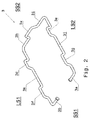
Fig. 2 , thewire spring 3 has several integrally connected portions, namely twospring end parts spring slot parts spring bar parts spring handle part 3x. - The
spring end parts wire spring 3. Thespring end parts - The spring handle
part 3x is placed between thespring bar parts 3h and 3i. Thespring bar parts 3h and 3i as well as thespring handle part 3x are located on the second short side SS2 of the rectangle. - The
spring bar part 3k is placed between thespring slot parts spring slot parts spring bar part 3k are located on the first long side LS1 of the rectangle. - Likewise, the
spring bar part 3j is placed between thespring slot parts spring slot parts spring bar part 3j are located on the second long side LS2 of the rectangle. - Comparing the first long side LS1 and the second long side LS2 of the rectangle, the
spring slot part 3e is placed opposite to thespring slot part 3d. Thespring slot part 3g is placed opposite to thespring slot part 3f. Thespring bar part 3j is placed opposite to thespring bar part 3k. - Comparing the first short side SS1 and the second short side SS2 of the rectangle, the
spring bar part 3h is placed opposite to thespring end part 3b. The spring bar part 3i is placed opposite to thespring end part 3a. - The
spring end part 3a is integrally connected to thespring slot part 3g, which is integrally connected to thespring bar part 3j . Thespring bar part 3j is integrally connected to thespring slot part 3e. Thespring slot part 3e is integrally connected to the spring bar part 3i, which is integrally connected to thespring handle part 3x. The spring handlepart 3x is integrally connected to thespring bar part 3h. Thespring bar part 3h is integrally connected to thespring latch part 3d. Thespring latch part 3d is integrally connected to thespring bar part 3k. Thespring bar part 3k is integrally connected to thespring slot part 3f. Thespring slot part 3f is integrally connected to theend part 3b. - The
metal wire spring 3 is produced using a metal extrusion process. - Referring to
Fig. 1 , thespring end parts spring holder parts wire spring 3 is rotatable about the axis 2c. In practise, thewire spring 3 can rotate about 180 degrees about the axis 2c. -
Fig. 3 shows acamera 1. Thecamera 1 includes a mainlyrectangular case 1f. Therectangular case 1f has four sides, namely a first long side SC1, a second long side SC2 that is positioned opposite to the first long side SC1, a front short side F, and a rear short side R that is positioned opposite to the front short side F. - The
case 1f also includes with fourcylindrical pins cylindrical pins rectangular case 1f. - The cylindrical pins 1b and 1d are located on the first long side SC1 of the
rectangular case 1f. Likewise, thecylindrical pins rectangular case 1f. Thecylindrical pin 1a is placed opposite to thecylindrical pin 1b while thecylindrical pin 1c is placed opposite to thecylindrical pin 1d. - The
camera 1 also comprises includes alens 1e, which is intended for facing the front short side F, which is intended for directed at a driving or moving direction of a vehicle, when the camera is mounted on a windscreen of the vehicle. - In use, the
bracket unit 5 is intended for attaching to an interior part of a vehicle, such as windscreen, and for receiving and for fastening onto thecamera 1. -
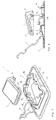
Figs. 4 and 5 show thebracket unit 5 being placed in an unlocked position and thecamera 1 being placed in a first camera position. In the unlocked position, thewire spring 3 is rotated away from the rectangular bracket plate 2p. In detail, a user pushes thespring handle part 3x such that thespring bar parts 3h and 3i of thewire spring 3 are rotated away from the corresponding thebracket hook parts 2h and 2i of thebracket 2. - The
wire spring 3 is placed in a relaxed or uncompressed state. - The
wire spring 3 and thebracket 2 are also placed to receive thecamera 1. - The
spring slot part 3f of thewire spring 3 and thebracket slot part 2f of thebracket 2 are positioned to receive thecylindrical pin 1c of thecamera 1. Similarly, thespring slot part 3d and thebracket slot part 2d are positioned to receive thecylindrical pin 1a. Thespring slot part 3e and thebracket slot part 2e are positioned to receive thecylindrical pin 1b. Thespring slot part 3g and thebracket slot part 2g are positioned to receive thecylindrical pin 1d. - This position of the
wire spring 3 and thebracket 2 also allow removal of thecamera 1 from thebracket unit 5. - In the first camera position, the
camera 1 is placed in the vicinity of thebracket 2. - After this, the
camera 1 can be placed in a second camera position, which is shown inFigs. 6 and 7 . - In the second camera position, the
camera 1 is placed next to thebracket 2. Thecamera 1 contacts thebracket 2, wherein thebracket 2 supports the weight of thecamera 1. - In detail, the
cylindrical pins camera 1 are placed next to the correspondingbracket slot parts bracket 2. Thecylindrical pins bracket slot parts bracket slot parts cylindrical pins - Following this, the
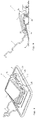
camera 1 can be placed in the third position, which is shown inFigs. 8 and 9 . - In the third camera position, the
camera 1 is placed in a predetermined camera attachment position. - The
camera 1 is placed next to thebracket 2 while thecamera 1 is pushed toward the bracketspring holder parts bracket 2, as shown by an arrow inFig. 9 . The cylindrical pins 1b and 1a are then blocked by the corresponding blocking surfaces of the respectivebracket slot part camera 1 is then aligned and is positioned in the predetermined camera attachment position. - After this, the
bracket unit 5 can be placed in a locked position, which is shown inFigs 10 and 11 . - In the locking position, the
camera 1 is then enclosed by thebracket 2 and the wire spring 4 and is fastened onto thebracket 2 and the wire spring 4. - The
wire spring 3 is rotated such that thespring bar parts wire spring 3 are fastened onto thebracket hook parts bracket 2. Thespring bar parts bracket 2 while thebracket hook parts spring bar parts spring bar parts bracket 2. - As better seen in
Fig. 10, 11 , and12 , thecylindrical pin 1c of thecamera 1 is enclosed by thespring slot part 3f of thewire spring 3 and by thebracket slot part 2f of thebracket 2, wherein thecylindrical pin 1c is gripped by thespring slot part 3f and by thebracket slot part 2f. In effect, thecylindrical pin 1c is prevented from moving with respect to thespring slot part 3f and to thebracket slot part 2f. - Similarly, the
cylindrical pin 1a is also enclosed by thespring slot part 3d and by thebracket slot part 2d, wherein thecylindrical pin 1a is gripped by thespring slot part 3d and thebracket slot part 2d. - The
cylindrical pin 1b is also enclosed by thespring slot part 3e and by thebracket slot part 2e, wherein thecylindrical pin 1b is gripped by thespring slot part 3e and thebracket slot part 2e. - The
cylindrical pin 1d is also enclosed by thespring slot part 3g and by thebracket slot part 2g, wherein thecylindrical pin 1d is gripped by thespring slot part 3g and thebracket slot part 2g. - The
camera 1 is hence prevented from shifting with respect to thebracket 2. - A method of using the
bracket unit 5 is described below. - The method includes a bracket assembly step, a camera mounting step, and a camera dismounting step.
- In the bracket assembly step, the
spring end parts wire spring 3 are inserted to the corresponding bracketspring holder parts bracket 2 such that thewire spring 3 is rotatably connected to thebracket 2. - The flat major surface of the
bracket 2 is later attached to a windscreen of a car. - Following this, the camera mounting step can be performed.
- In the camera mounting step, the
bracket unit 5 is placed in the unlocked position, wherein thebracket unit 5 is positioned to receive thecamera 1. Thewire spring 3 is rotated away from the rectangular bracket plate 2p and thewire spring 3 is placed in a relaxed state. - The
camera 1 is afterward placed next to thebracket 2 such that thecylindrical pins camera 1 are placed next to the correspondingbracket slot parts bracket 2. - Following this, the
camera 1 is pushed towards the bracketspring holder parts bracket 2, for placing thecamera 1 in the predetermined camera attachment position. - The
bracket unit 5 can later be placed in the locked position, wherein thebracket unit 5 is fastened onto thecamera 1. Thewire spring 3 is rotated such that thebracket hook parts spring bar parts wire spring 3 is then placed in the compressed position. - The camera dismounting step can be performed after this.
- In the camera dismounting step, the
bracket unit 5 is placed in the unlocked position, wherein thewire spring 3 is rotated away from the rectangular bracket plate 2p and thebracket unit 5 is placed to release thecamera 1. - The
camera 1 can then be removed from thebracket 2. - In a general sense, other sensors, such as a rain sensor, can replace the
camera 1. - The
bracket unit 5 provides several benefits. - The metal properties of the
metal wire spring 3 allows thewire spring 3 to maintain its elasticity essentially over a long period of time even in high temperatures. In other words, thewire spring 3 can be restored to its original shape after being stretched, even after a long period of use at high temperatures. - The production of the
wire spring 3 also does not require complex tools. It can be produced using technology for bending metal wires and pipes. - The design of the
bracket 2 is simple. - The
bracket unit 5 can align thecamera 1 to a predetermined fastening position before the camera is fastened onto thebracket unit 5. - The
bracket unit 5 can be produced easily with assembly of only two parts. - The
bracket unit 5 can be easily adapted for fastening different types of camera onto a windshield of a car. - Although the above description contains much specificity, this should not be construed as limiting the scope of the embodiments but merely providing illustration of the foreseeable embodiments. The above stated advantages of the embodiments should not be construed especially as limiting the scope of the embodiments but merely to explain possible achievements if the described embodiments are put into practice. Thus, the scope of the embodiments should be determined by the claims and their equivalents, rather than by the examples given.
-
- 1
- camera
- 1a
- cylindrical pin
- 1b
- cylindrical pin
- 1c
- cylindrical pin
- 1d
- cylindrical pin
- 1e
- lens
- 1f
- case
- 2
- bracket
- 2a
- bracket spring holder part
- 2b
- bracket spring holder part
- 2c
- axis
- 2d
- bracket slot part
- 2e
- bracket slot part
- 2f
- bracket slot part
- 2g
- bracket slot part
- 2h
- bracket hook part
- 2i
- bracket hook part
- 2j
- bracket hook part
- 2k
- bracket hook part
- 2p
- bracket plate
- 3
- wire spring
- 3a
- spring end part
- 3b
- spring end part
- 3d
- spring slot part
- 3e
- spring slot part
- 3f
- spring slot part
- 3g
- spring slot part
- 3h
- spring bar part
- 3i
- spring bar part
- 3j
- spring bar part
- 3k
- spring bar part
- 3x
- spring handle part
- 5
- bracket unit
- L1
- bracket first long side
- L2
- bracket second long side
- S1
- bracket first short side
- S2
- bracket second short side
- F
- camera front side
- R
- camera rear side
- SC1
- camera first side
- SC2
- camera second side
- LS1
- spring first long side
- LS2
- spring second long side
- SS1
- spring first short side
- SS2
- spring second short side
Claims (12)
- A bracket unit for holding a vehicle sensor, the bracket unit comprising a bracket and a metal wire spring,the bracket comprising- at least one bracket holder,- at least one bracket hook part, and- at least one bracket slot part, andthe metal wire spring comprising an elongated body with an essentially circular cross-section, the body comprisingwherein the bracket unit provides a vehicle sensor receiving position and a vehicle sensor fastening position,- at least one spring hinge part being rotatably attached to the at least one bracket holder part,- at least one spring bar part, and- at least one spring slot part,- in the vehicle sensor receiving position, the metal wire spring is positioned such that the spring slot part and the bracket slot part are positioned for receiving the vehicle sensor, and- in the vehicle sensor fastening position, the metal wire spring is positioned such that the spring bar part is fastened onto the bracket hook part and that the spring slot part and the bracket slot part are positioned for fastening onto the vehicle sensor.
- The bracket unit according to claim 1, wherein the spring hinge part is provided at one end of the metal wire spring.
- The bracket unit according to claim 1 or 2, wherein the metal wire spring comprises a spring handle part that is adapted for holding by a user.
- The bracket unit according to one of the above-mentioned claims, wherein
the bracket comprises plastic material. - The bracket unit according to one of the above-mentioned claims, wherein
the metal wire spring is bent to form an essentially rectangular shape. - The bracket unit according to one of the above-mentioned claims, wherein
the bracket comprises two bracket holder parts and the metal wire spring comprises two corresponding spring hinge parts. - The bracket unit according to one of the above-mentioned claims, wherein
the bracket comprises four bracket hook parts and the metal wire spring comprises four corresponding spring bar parts. - The bracket unit according to one of the above-mentioned claims, wherein
the bracket comprises four bracket slot parts and the metal wire spring comprises four corresponding spring slot parts. - A combination of a vehicle sensor case and a bracket unit according to one of the above-mentioned claims, wherein the vehicle sensor case is fastened onto the bracket unit.
- The combination according to claim 9, wherein
the vehicle sensor case comprises a camera unit case. - A vehicle comprisinga combination of a vehicle sensor case and a bracket unit according to claim 9 or 10,wherein the vehicle sensor case is fastened onto the bracket unit and the bracket units is provided fastening onto an interior part of the vehicle.
- A method for a bracket unit to fasten onto a vehicle sensor, the bracket unit comprising a bracket and a metal wire spring, the method comprisinga vehicle sensor receiving step anda vehicle sensor fastening step, whereinthe vehicle sensor receiving step comprises- positioning the metal wire spring such that a spring slot part of the metal wire spring and a bracket slot part of the bracket are positioned for receiving the vehicle sensor, andthe vehicle sensor fastening step comprises- positioning the metal wire spring such that a spring bar part of the metal wire spring is fastened onto a bracket hook part of the bracket and that the spring slot part and the bracket slot part are positioned for fastening onto the vehicle sensor.
Priority Applications (1)
| Application Number | Priority Date | Filing Date | Title |
|---|---|---|---|
| EP15465560.9A EP3173290B1 (en) | 2015-11-26 | 2015-11-26 | Camera bracket with metal wire spring |
Applications Claiming Priority (1)
| Application Number | Priority Date | Filing Date | Title |
|---|---|---|---|
| EP15465560.9A EP3173290B1 (en) | 2015-11-26 | 2015-11-26 | Camera bracket with metal wire spring |
Publications (2)
| Publication Number | Publication Date |
|---|---|
| EP3173290A1 true EP3173290A1 (en) | 2017-05-31 |
| EP3173290B1 EP3173290B1 (en) | 2019-01-30 |
Family
ID=55024981
Family Applications (1)
| Application Number | Title | Priority Date | Filing Date |
|---|---|---|---|
| EP15465560.9A Active EP3173290B1 (en) | 2015-11-26 | 2015-11-26 | Camera bracket with metal wire spring |
Country Status (1)
| Country | Link |
|---|---|
| EP (1) | EP3173290B1 (en) |
Cited By (11)
| Publication number | Priority date | Publication date | Assignee | Title |
|---|---|---|---|---|
| WO2018190116A1 (en) * | 2017-04-13 | 2018-10-18 | 日立オートモティブシステムズ株式会社 | Image capture device |
| DE102017210291A1 (en) * | 2017-06-20 | 2018-12-20 | Continental Automotive Gmbh | Holder for mounting a sensor, in particular radar sensor, to a vehicle and a system comprising a holder and the sensor |
| EP3466767A1 (en) * | 2017-10-05 | 2019-04-10 | Veoneer Sweden AB | Attachment for a camera module in a camera housing and a camera module |
| DE102018205723A1 (en) * | 2018-04-16 | 2019-10-17 | Mahle International Gmbh | Arrangement with a clamping spring |
| EP3566907A1 (en) * | 2018-05-08 | 2019-11-13 | Volvo Car Corporation | Bracket for fixating a housing comprising a camera |
| CN111247037A (en) * | 2017-10-23 | 2020-06-05 | 五十铃自动车株式会社 | Mounting structure for vehicle-mounted component |
| EP3770021A1 (en) * | 2019-07-25 | 2021-01-27 | Nifco Inc. | Bracket for in-vehicle device and holding device for in-vehicle device |
| FR3115006A1 (en) * | 2020-10-08 | 2022-04-15 | Renault | Mounting bracket for an optical sensor on a glazed surface of a vehicle. |
| EP4140822A1 (en) * | 2021-08-25 | 2023-03-01 | Bayerische Motoren Werke Aktiengesellschaft | Mounting device for a perimeter sensor and sensor assembly system for a vehicle |
| US11662423B2 (en) | 2017-06-20 | 2023-05-30 | Conti Temic Microelectronic Gmbh | Holder for fixing a sensor, in particular radar sensor, to a vehicle, and system comprising a holder and the sensor |
| DE102022208409A1 (en) | 2022-08-12 | 2024-02-15 | Volkswagen Aktiengesellschaft | Holding device for holding a sensor on a vehicle component and vehicle component with a holding device |
Families Citing this family (1)
| Publication number | Priority date | Publication date | Assignee | Title |
|---|---|---|---|---|
| WO2024035891A1 (en) * | 2022-08-10 | 2024-02-15 | Illinois Tool Works Inc. | Bracket assembly |
Citations (6)
| Publication number | Priority date | Publication date | Assignee | Title |
|---|---|---|---|---|
| DE102006061308A1 (en) * | 2006-12-22 | 2008-06-26 | Leopold Kostal Gmbh & Co. Kg | bracket |
| DE102009011614A1 (en) * | 2009-03-04 | 2010-09-09 | Leopold Kostal Gmbh & Co. Kg | Sensor assembly, for mounting at a motor vehicle windscreen, has a double twin-leg wire spring to press the housing against the windscreen |
| US20110233248A1 (en) | 2008-10-04 | 2011-09-29 | Daimler Ag | Carrier Device For Attaching To A Pane Of A Motor Vehicle |
| US20120207461A1 (en) | 2011-02-10 | 2012-08-16 | Denso Corporation | In-vehicle camera |
| DE102012011596B3 (en) * | 2012-06-13 | 2013-07-04 | Decoma (Germany) Gmbh | cradle |
| WO2014141357A1 (en) * | 2013-03-11 | 2014-09-18 | 本田技研工業株式会社 | Camera unit, vehicle, and method for manufacturing camera unit |
-
2015
- 2015-11-26 EP EP15465560.9A patent/EP3173290B1/en active Active
Patent Citations (6)
| Publication number | Priority date | Publication date | Assignee | Title |
|---|---|---|---|---|
| DE102006061308A1 (en) * | 2006-12-22 | 2008-06-26 | Leopold Kostal Gmbh & Co. Kg | bracket |
| US20110233248A1 (en) | 2008-10-04 | 2011-09-29 | Daimler Ag | Carrier Device For Attaching To A Pane Of A Motor Vehicle |
| DE102009011614A1 (en) * | 2009-03-04 | 2010-09-09 | Leopold Kostal Gmbh & Co. Kg | Sensor assembly, for mounting at a motor vehicle windscreen, has a double twin-leg wire spring to press the housing against the windscreen |
| US20120207461A1 (en) | 2011-02-10 | 2012-08-16 | Denso Corporation | In-vehicle camera |
| DE102012011596B3 (en) * | 2012-06-13 | 2013-07-04 | Decoma (Germany) Gmbh | cradle |
| WO2014141357A1 (en) * | 2013-03-11 | 2014-09-18 | 本田技研工業株式会社 | Camera unit, vehicle, and method for manufacturing camera unit |
Cited By (20)
| Publication number | Priority date | Publication date | Assignee | Title |
|---|---|---|---|---|
| US10994667B2 (en) | 2017-04-13 | 2021-05-04 | Hitachi Automotive Systems, Ltd. | Image capture device |
| WO2018190116A1 (en) * | 2017-04-13 | 2018-10-18 | 日立オートモティブシステムズ株式会社 | Image capture device |
| DE102017210291A1 (en) * | 2017-06-20 | 2018-12-20 | Continental Automotive Gmbh | Holder for mounting a sensor, in particular radar sensor, to a vehicle and a system comprising a holder and the sensor |
| US11662423B2 (en) | 2017-06-20 | 2023-05-30 | Conti Temic Microelectronic Gmbh | Holder for fixing a sensor, in particular radar sensor, to a vehicle, and system comprising a holder and the sensor |
| EP3466767A1 (en) * | 2017-10-05 | 2019-04-10 | Veoneer Sweden AB | Attachment for a camera module in a camera housing and a camera module |
| CN111247037A (en) * | 2017-10-23 | 2020-06-05 | 五十铃自动车株式会社 | Mounting structure for vehicle-mounted component |
| DE102018205723A1 (en) * | 2018-04-16 | 2019-10-17 | Mahle International Gmbh | Arrangement with a clamping spring |
| DE102018205723B4 (en) | 2018-04-16 | 2023-01-19 | Mahle International Gmbh | Arrangement with a clamping spring |
| CN110450729A (en) * | 2018-05-08 | 2019-11-15 | 沃尔沃汽车公司 | Bracket for the fixed shell including video camera |
| US10596981B2 (en) | 2018-05-08 | 2020-03-24 | Volvo Car Corporation | Bracket for fixating a housing comprising a camera |
| CN110450729B (en) * | 2018-05-08 | 2023-02-17 | 沃尔沃汽车公司 | Holder for fixing a housing comprising a camera |
| EP3566907A1 (en) * | 2018-05-08 | 2019-11-13 | Volvo Car Corporation | Bracket for fixating a housing comprising a camera |
| CN112277821A (en) * | 2019-07-25 | 2021-01-29 | 株式会社利富高 | Bracket for vehicle-mounted device and holding device for vehicle-mounted device |
| EP3770021A1 (en) * | 2019-07-25 | 2021-01-27 | Nifco Inc. | Bracket for in-vehicle device and holding device for in-vehicle device |
| US11338742B2 (en) * | 2019-07-25 | 2022-05-24 | Nifco Inc. | Bracket for in-vehicle device and holding device for in-vehicle device |
| CN112277821B (en) * | 2019-07-25 | 2023-12-15 | 株式会社利富高 | Support for vehicle-mounted device and holding device for vehicle-mounted device |
| FR3115006A1 (en) * | 2020-10-08 | 2022-04-15 | Renault | Mounting bracket for an optical sensor on a glazed surface of a vehicle. |
| EP4140822A1 (en) * | 2021-08-25 | 2023-03-01 | Bayerische Motoren Werke Aktiengesellschaft | Mounting device for a perimeter sensor and sensor assembly system for a vehicle |
| WO2023025499A1 (en) * | 2021-08-25 | 2023-03-02 | Bayerische Motoren Werke Aktiengesellschaft | Fastening device for an environmental sensor, and sensor installation system for a vehicle |
| DE102022208409A1 (en) | 2022-08-12 | 2024-02-15 | Volkswagen Aktiengesellschaft | Holding device for holding a sensor on a vehicle component and vehicle component with a holding device |
Also Published As
| Publication number | Publication date |
|---|---|
| EP3173290B1 (en) | 2019-01-30 |
Similar Documents
| Publication | Publication Date | Title |
|---|---|---|
| EP3173290A1 (en) | Camera bracket with metal wire spring | |
| EP3173289B1 (en) | Camera bracket with metal wire spring | |
| CN104044516B (en) | Fixing mechanism for fixing portable electronic device and electronic equipment thereof | |
| CN105229557A (en) | Adjustable portable equipment support | |
| US7784847B2 (en) | Sun visor for vehicles | |
| WO2009000987A3 (en) | Universal fastener for any type of application in relation to an internal rear-view mirror | |
| US20160362067A1 (en) | Support for attaching a portable device to a vehicle rear-view mirror | |
| ATE541731T1 (en) | SUN VISOR FOR A VEHICLE | |
| US8474110B1 (en) | Clip apparatus | |
| EP2149477A3 (en) | Mounting system for mounting an electronic device on a vehicle | |
| ATE384925T1 (en) | COOLING DEVICE FOR MOTOR VEHICLES | |
| CN110450729B (en) | Holder for fixing a housing comprising a camera | |
| US20110299843A1 (en) | Camera device and method for assembling camera device | |
| CN108533895B (en) | Support frame | |
| US11152140B2 (en) | Wire holder for assembling a wire harness | |
| US9730352B2 (en) | Clamp for panel-mounted electronics modules or other devices | |
| US20190271414A1 (en) | Receiving Device for Receiving a Line-Shaped Component | |
| US10059275B2 (en) | Roof molding cap attachment structure and roof molding | |
| JPH0517211U (en) | Lock device | |
| US20220219540A1 (en) | Operating unit for a vehicle | |
| EP3984839B1 (en) | Securing device for a windscreen wiper mounting assembly | |
| JP2007015585A (en) | Glass holder | |
| JP2019051852A (en) | Wiper blade | |
| JP2011161962A (en) | Sunglass for mounting visor | |
| JP2006182270A (en) | Clip for holding on-vehicle item |
Legal Events
| Date | Code | Title | Description |
|---|---|---|---|
| PUAI | Public reference made under article 153(3) epc to a published international application that has entered the european phase |
Free format text: ORIGINAL CODE: 0009012 |
|
| STAA | Information on the status of an ep patent application or granted ep patent |
Free format text: STATUS: THE APPLICATION HAS BEEN PUBLISHED |
|
| AK | Designated contracting states |
Kind code of ref document: A1 Designated state(s): AL AT BE BG CH CY CZ DE DK EE ES FI FR GB GR HR HU IE IS IT LI LT LU LV MC MK MT NL NO PL PT RO RS SE SI SK SM TR |
|
| AX | Request for extension of the european patent |
Extension state: BA ME |
|
| STAA | Information on the status of an ep patent application or granted ep patent |
Free format text: STATUS: REQUEST FOR EXAMINATION WAS MADE |
|
| 17P | Request for examination filed |
Effective date: 20171130 |
|
| RBV | Designated contracting states (corrected) |
Designated state(s): AL AT BE BG CH CY CZ DE DK EE ES FI FR GB GR HR HU IE IS IT LI LT LU LV MC MK MT NL NO PL PT RO RS SE SI SK SM TR |
|
| STAA | Information on the status of an ep patent application or granted ep patent |
Free format text: STATUS: EXAMINATION IS IN PROGRESS |
|
| 17Q | First examination report despatched |
Effective date: 20180424 |
|
| GRAP | Despatch of communication of intention to grant a patent |
Free format text: ORIGINAL CODE: EPIDOSNIGR1 |
|
| STAA | Information on the status of an ep patent application or granted ep patent |
Free format text: STATUS: GRANT OF PATENT IS INTENDED |
|
| INTG | Intention to grant announced |
Effective date: 20180925 |
|
| GRAS | Grant fee paid |
Free format text: ORIGINAL CODE: EPIDOSNIGR3 |
|
| GRAA | (expected) grant |
Free format text: ORIGINAL CODE: 0009210 |
|
| STAA | Information on the status of an ep patent application or granted ep patent |
Free format text: STATUS: THE PATENT HAS BEEN GRANTED |
|
| AK | Designated contracting states |
Kind code of ref document: B1 Designated state(s): AL AT BE BG CH CY CZ DE DK EE ES FI FR GB GR HR HU IE IS IT LI LT LU LV MC MK MT NL NO PL PT RO RS SE SI SK SM TR |
|
| REG | Reference to a national code |
Ref country code: GB Ref legal event code: FG4D |
|
| REG | Reference to a national code |
Ref country code: CH Ref legal event code: EP |
|
| REG | Reference to a national code |
Ref country code: AT Ref legal event code: REF Ref document number: 1092981 Country of ref document: AT Kind code of ref document: T Effective date: 20190215 |
|
| REG | Reference to a national code |
Ref country code: IE Ref legal event code: FG4D |
|
| REG | Reference to a national code |
Ref country code: DE Ref legal event code: R096 Ref document number: 602015023960 Country of ref document: DE |
|
| REG | Reference to a national code |
Ref country code: LT Ref legal event code: MG4D |
|
| REG | Reference to a national code |
Ref country code: NL Ref legal event code: MP Effective date: 20190130 |
|
| PG25 | Lapsed in a contracting state [announced via postgrant information from national office to epo] |
Ref country code: ES Free format text: LAPSE BECAUSE OF FAILURE TO SUBMIT A TRANSLATION OF THE DESCRIPTION OR TO PAY THE FEE WITHIN THE PRESCRIBED TIME-LIMIT Effective date: 20190130 Ref country code: NL Free format text: LAPSE BECAUSE OF FAILURE TO SUBMIT A TRANSLATION OF THE DESCRIPTION OR TO PAY THE FEE WITHIN THE PRESCRIBED TIME-LIMIT Effective date: 20190130 Ref country code: LT Free format text: LAPSE BECAUSE OF FAILURE TO SUBMIT A TRANSLATION OF THE DESCRIPTION OR TO PAY THE FEE WITHIN THE PRESCRIBED TIME-LIMIT Effective date: 20190130 Ref country code: NO Free format text: LAPSE BECAUSE OF FAILURE TO SUBMIT A TRANSLATION OF THE DESCRIPTION OR TO PAY THE FEE WITHIN THE PRESCRIBED TIME-LIMIT Effective date: 20190430 Ref country code: FI Free format text: LAPSE BECAUSE OF FAILURE TO SUBMIT A TRANSLATION OF THE DESCRIPTION OR TO PAY THE FEE WITHIN THE PRESCRIBED TIME-LIMIT Effective date: 20190130 Ref country code: PL Free format text: LAPSE BECAUSE OF FAILURE TO SUBMIT A TRANSLATION OF THE DESCRIPTION OR TO PAY THE FEE WITHIN THE PRESCRIBED TIME-LIMIT Effective date: 20190130 Ref country code: PT Free format text: LAPSE BECAUSE OF FAILURE TO SUBMIT A TRANSLATION OF THE DESCRIPTION OR TO PAY THE FEE WITHIN THE PRESCRIBED TIME-LIMIT Effective date: 20190530 Ref country code: SE Free format text: LAPSE BECAUSE OF FAILURE TO SUBMIT A TRANSLATION OF THE DESCRIPTION OR TO PAY THE FEE WITHIN THE PRESCRIBED TIME-LIMIT Effective date: 20190130 |
|
| REG | Reference to a national code |
Ref country code: AT Ref legal event code: MK05 Ref document number: 1092981 Country of ref document: AT Kind code of ref document: T Effective date: 20190130 |
|
| PG25 | Lapsed in a contracting state [announced via postgrant information from national office to epo] |
Ref country code: BG Free format text: LAPSE BECAUSE OF FAILURE TO SUBMIT A TRANSLATION OF THE DESCRIPTION OR TO PAY THE FEE WITHIN THE PRESCRIBED TIME-LIMIT Effective date: 20190430 Ref country code: HR Free format text: LAPSE BECAUSE OF FAILURE TO SUBMIT A TRANSLATION OF THE DESCRIPTION OR TO PAY THE FEE WITHIN THE PRESCRIBED TIME-LIMIT Effective date: 20190130 Ref country code: RS Free format text: LAPSE BECAUSE OF FAILURE TO SUBMIT A TRANSLATION OF THE DESCRIPTION OR TO PAY THE FEE WITHIN THE PRESCRIBED TIME-LIMIT Effective date: 20190130 Ref country code: IS Free format text: LAPSE BECAUSE OF FAILURE TO SUBMIT A TRANSLATION OF THE DESCRIPTION OR TO PAY THE FEE WITHIN THE PRESCRIBED TIME-LIMIT Effective date: 20190530 Ref country code: LV Free format text: LAPSE BECAUSE OF FAILURE TO SUBMIT A TRANSLATION OF THE DESCRIPTION OR TO PAY THE FEE WITHIN THE PRESCRIBED TIME-LIMIT Effective date: 20190130 Ref country code: GR Free format text: LAPSE BECAUSE OF FAILURE TO SUBMIT A TRANSLATION OF THE DESCRIPTION OR TO PAY THE FEE WITHIN THE PRESCRIBED TIME-LIMIT Effective date: 20190501 |
|
| PG25 | Lapsed in a contracting state [announced via postgrant information from national office to epo] |
Ref country code: RO Free format text: LAPSE BECAUSE OF FAILURE TO SUBMIT A TRANSLATION OF THE DESCRIPTION OR TO PAY THE FEE WITHIN THE PRESCRIBED TIME-LIMIT Effective date: 20190130 Ref country code: IT Free format text: LAPSE BECAUSE OF FAILURE TO SUBMIT A TRANSLATION OF THE DESCRIPTION OR TO PAY THE FEE WITHIN THE PRESCRIBED TIME-LIMIT Effective date: 20190130 Ref country code: CZ Free format text: LAPSE BECAUSE OF FAILURE TO SUBMIT A TRANSLATION OF THE DESCRIPTION OR TO PAY THE FEE WITHIN THE PRESCRIBED TIME-LIMIT Effective date: 20190130 Ref country code: SK Free format text: LAPSE BECAUSE OF FAILURE TO SUBMIT A TRANSLATION OF THE DESCRIPTION OR TO PAY THE FEE WITHIN THE PRESCRIBED TIME-LIMIT Effective date: 20190130 Ref country code: AL Free format text: LAPSE BECAUSE OF FAILURE TO SUBMIT A TRANSLATION OF THE DESCRIPTION OR TO PAY THE FEE WITHIN THE PRESCRIBED TIME-LIMIT Effective date: 20190130 Ref country code: EE Free format text: LAPSE BECAUSE OF FAILURE TO SUBMIT A TRANSLATION OF THE DESCRIPTION OR TO PAY THE FEE WITHIN THE PRESCRIBED TIME-LIMIT Effective date: 20190130 Ref country code: DK Free format text: LAPSE BECAUSE OF FAILURE TO SUBMIT A TRANSLATION OF THE DESCRIPTION OR TO PAY THE FEE WITHIN THE PRESCRIBED TIME-LIMIT Effective date: 20190130 |
|
| REG | Reference to a national code |
Ref country code: DE Ref legal event code: R097 Ref document number: 602015023960 Country of ref document: DE |
|
| PG25 | Lapsed in a contracting state [announced via postgrant information from national office to epo] |
Ref country code: SM Free format text: LAPSE BECAUSE OF FAILURE TO SUBMIT A TRANSLATION OF THE DESCRIPTION OR TO PAY THE FEE WITHIN THE PRESCRIBED TIME-LIMIT Effective date: 20190130 |
|
| PLBE | No opposition filed within time limit |
Free format text: ORIGINAL CODE: 0009261 |
|
| STAA | Information on the status of an ep patent application or granted ep patent |
Free format text: STATUS: NO OPPOSITION FILED WITHIN TIME LIMIT |
|
| PG25 | Lapsed in a contracting state [announced via postgrant information from national office to epo] |
Ref country code: AT Free format text: LAPSE BECAUSE OF FAILURE TO SUBMIT A TRANSLATION OF THE DESCRIPTION OR TO PAY THE FEE WITHIN THE PRESCRIBED TIME-LIMIT Effective date: 20190130 |
|
| 26N | No opposition filed |
Effective date: 20191031 |
|
| PG25 | Lapsed in a contracting state [announced via postgrant information from national office to epo] |
Ref country code: SI Free format text: LAPSE BECAUSE OF FAILURE TO SUBMIT A TRANSLATION OF THE DESCRIPTION OR TO PAY THE FEE WITHIN THE PRESCRIBED TIME-LIMIT Effective date: 20190130 |
|
| PG25 | Lapsed in a contracting state [announced via postgrant information from national office to epo] |
Ref country code: TR Free format text: LAPSE BECAUSE OF FAILURE TO SUBMIT A TRANSLATION OF THE DESCRIPTION OR TO PAY THE FEE WITHIN THE PRESCRIBED TIME-LIMIT Effective date: 20190130 |
|
| REG | Reference to a national code |
Ref country code: CH Ref legal event code: PL |
|
| PG25 | Lapsed in a contracting state [announced via postgrant information from national office to epo] |
Ref country code: CH Free format text: LAPSE BECAUSE OF NON-PAYMENT OF DUE FEES Effective date: 20191130 Ref country code: LI Free format text: LAPSE BECAUSE OF NON-PAYMENT OF DUE FEES Effective date: 20191130 Ref country code: MC Free format text: LAPSE BECAUSE OF FAILURE TO SUBMIT A TRANSLATION OF THE DESCRIPTION OR TO PAY THE FEE WITHIN THE PRESCRIBED TIME-LIMIT Effective date: 20190130 Ref country code: LU Free format text: LAPSE BECAUSE OF NON-PAYMENT OF DUE FEES Effective date: 20191126 |
|
| REG | Reference to a national code |
Ref country code: BE Ref legal event code: MM Effective date: 20191130 |
|
| GBPC | Gb: european patent ceased through non-payment of renewal fee |
Effective date: 20191126 |
|
| PG25 | Lapsed in a contracting state [announced via postgrant information from national office to epo] |
Ref country code: GB Free format text: LAPSE BECAUSE OF NON-PAYMENT OF DUE FEES Effective date: 20191126 Ref country code: FR Free format text: LAPSE BECAUSE OF NON-PAYMENT OF DUE FEES Effective date: 20191130 Ref country code: IE Free format text: LAPSE BECAUSE OF NON-PAYMENT OF DUE FEES Effective date: 20191126 |
|
| PG25 | Lapsed in a contracting state [announced via postgrant information from national office to epo] |
Ref country code: BE Free format text: LAPSE BECAUSE OF NON-PAYMENT OF DUE FEES Effective date: 20191130 |
|
| PG25 | Lapsed in a contracting state [announced via postgrant information from national office to epo] |
Ref country code: CY Free format text: LAPSE BECAUSE OF FAILURE TO SUBMIT A TRANSLATION OF THE DESCRIPTION OR TO PAY THE FEE WITHIN THE PRESCRIBED TIME-LIMIT Effective date: 20190130 |
|
| PG25 | Lapsed in a contracting state [announced via postgrant information from national office to epo] |
Ref country code: HU Free format text: LAPSE BECAUSE OF FAILURE TO SUBMIT A TRANSLATION OF THE DESCRIPTION OR TO PAY THE FEE WITHIN THE PRESCRIBED TIME-LIMIT; INVALID AB INITIO Effective date: 20151126 Ref country code: MT Free format text: LAPSE BECAUSE OF FAILURE TO SUBMIT A TRANSLATION OF THE DESCRIPTION OR TO PAY THE FEE WITHIN THE PRESCRIBED TIME-LIMIT Effective date: 20190130 |
|
| PG25 | Lapsed in a contracting state [announced via postgrant information from national office to epo] |
Ref country code: MK Free format text: LAPSE BECAUSE OF FAILURE TO SUBMIT A TRANSLATION OF THE DESCRIPTION OR TO PAY THE FEE WITHIN THE PRESCRIBED TIME-LIMIT Effective date: 20190130 |
|
| REG | Reference to a national code |
Ref country code: DE Ref legal event code: R081 Ref document number: 602015023960 Country of ref document: DE Owner name: CONTINENTAL AUTONOMOUS MOBILITY GERMANY GMBH, DE Free format text: FORMER OWNER: CONTINENTAL AUTOMOTIVE GMBH, 30165 HANNOVER, DE |
|
| PGFP | Annual fee paid to national office [announced via postgrant information from national office to epo] |
Ref country code: DE Payment date: 20231130 Year of fee payment: 9 |