EP3173274A1 - Vehicle body structure - Google Patents
Vehicle body structure Download PDFInfo
- Publication number
- EP3173274A1 EP3173274A1 EP16200485.7A EP16200485A EP3173274A1 EP 3173274 A1 EP3173274 A1 EP 3173274A1 EP 16200485 A EP16200485 A EP 16200485A EP 3173274 A1 EP3173274 A1 EP 3173274A1
- Authority
- EP
- European Patent Office
- Prior art keywords
- tank
- vehicle
- spare tire
- guard bar
- vehicle body
- Prior art date
- Legal status (The legal status is an assumption and is not a legal conclusion. Google has not performed a legal analysis and makes no representation as to the accuracy of the status listed.)
- Granted
Links
Images



Classifications
-
- B—PERFORMING OPERATIONS; TRANSPORTING
- B60—VEHICLES IN GENERAL
- B60K—ARRANGEMENT OR MOUNTING OF PROPULSION UNITS OR OF TRANSMISSIONS IN VEHICLES; ARRANGEMENT OR MOUNTING OF PLURAL DIVERSE PRIME-MOVERS IN VEHICLES; AUXILIARY DRIVES FOR VEHICLES; INSTRUMENTATION OR DASHBOARDS FOR VEHICLES; ARRANGEMENTS IN CONNECTION WITH COOLING, AIR INTAKE, GAS EXHAUST OR FUEL SUPPLY OF PROPULSION UNITS IN VEHICLES
- B60K13/00—Arrangement in connection with combustion air intake or gas exhaust of propulsion units
- B60K13/04—Arrangement in connection with combustion air intake or gas exhaust of propulsion units concerning exhaust
-
- B—PERFORMING OPERATIONS; TRANSPORTING
- B62—LAND VEHICLES FOR TRAVELLING OTHERWISE THAN ON RAILS
- B62D—MOTOR VEHICLES; TRAILERS
- B62D21/00—Understructures, i.e. chassis frame on which a vehicle body may be mounted
- B62D21/02—Understructures, i.e. chassis frame on which a vehicle body may be mounted comprising longitudinally or transversely arranged frame members
-
- B—PERFORMING OPERATIONS; TRANSPORTING
- B62—LAND VEHICLES FOR TRAVELLING OTHERWISE THAN ON RAILS
- B62D—MOTOR VEHICLES; TRAILERS
- B62D43/00—Spare wheel stowing, holding, or mounting arrangements
- B62D43/02—Spare wheel stowing, holding, or mounting arrangements external to the vehicle body
- B62D43/04—Spare wheel stowing, holding, or mounting arrangements external to the vehicle body attached beneath the vehicle body
-
- F—MECHANICAL ENGINEERING; LIGHTING; HEATING; WEAPONS; BLASTING
- F01—MACHINES OR ENGINES IN GENERAL; ENGINE PLANTS IN GENERAL; STEAM ENGINES
- F01N—GAS-FLOW SILENCERS OR EXHAUST APPARATUS FOR MACHINES OR ENGINES IN GENERAL; GAS-FLOW SILENCERS OR EXHAUST APPARATUS FOR INTERNAL-COMBUSTION ENGINES
- F01N2610/00—Adding substances to exhaust gases
- F01N2610/14—Arrangements for the supply of substances, e.g. conduits
- F01N2610/1406—Storage means for substances, e.g. tanks or reservoirs
Definitions
- the present invention relates to a vehicle body structure equipped with a tank of additive for exhaust purification.
- a vehicle equipped with an exhaust purification system for purifying the exhaust gas of the engine a vehicle equipped with a tank of the additive having a reduction action on the purification target substance has been known.
- the purification target substance is nitrogen oxides (NOx)
- additive such as aqueous urea solution or aqueous ammonia solution is stored inside the tank.
- an arrangement position of the tank for example, is suggested to be set on a bottom of a vehicle body that is an external space of a vehicle interior.
- the present invention has been made in view of the aforementioned problems, and an object thereof is to provide a vehicle body structure capable of improving the protection of the tank, while saving a space. Further, without being limited to this object, another object of the present invention is to obtain the function and effect that cannot be obtained by conventional techniques, as a function and effect derived from each configuration illustrated in "DESCRIPTION OF EMBODIMENTS" to be described later.
- the vehicle body structure of the present embodiment is applied to a vehicle 10 illustrated in Fig. 1 .
- the vehicle 10 is a pick-up truck type SUV (Sport Utility Vehicle) vehicle equipped with a urea SCR system.
- a separate frame structure in which the frame and the vehicle body are separated is employed.
- a box-like cab (vehicle interior) on which an occupant gets is disposed, and a platform 11 is disposed on the rear side thereof.
- the vehicle 10 is ordinarily equipped with a tank 3 that stores an additive for exhaust purification (for example, an aqueous urea solution, aqueous ammonia solution or the like).
- the urea SCR system is a kind of exhaust purification systems for purifying nitrogen oxide (NOx) contained in the exhaust gas of the engine.
- NOx nitrogen oxide
- the aqueous urea solution is injected to the upstream side of a NOx selective reduction catalyst interposed on an exhaust passage, and NOx is reduced to nitrogen on the catalyst, using ammonia generated by the hydrolysis of urea as a reducing agent.
- This kind of the urea SCR system is widely used in vehicles, working machines, vessels and power plants equipped with a diesel engine or a lean-burn engine.
- the vehicle 10 is provided with a pair of side members 1 and a cross member 2 which serve as a frame.
- the side members 1 are hollow cylindrical structural members which are disposed at intervals in a vehicle width direction (a left-right direction), and extend in a vehicle length direction (a front-rear direction) of the vehicle 10.
- the cross member 2 is a structural member which connects the left and right side members 1 in a ladder shape, and are provided at a plurality of positions at intervals in the front-rear direction.
- the arrangement direction of the side members 1 and the cross member 2 is a substantially horizontal direction.
- a cab and the platform 11 of the vehicle 10 are mounted on the frame via a vibration damping mount member.
- a tank 3, a spare tire 7, a guard bar 8 and a bumper 9 are provided on the bottom surface side of the platform 11 of the vehicle 10.
- the spare tire 7 is fixed to a spare tire bracket 19 disposed behind an axle 22 of a rear wheel 21 so as to be attachable and detachable via fixtures 12 (see Fig. 3 ).
- the spare tire bracket 19 is a member that is attached to extend between the left and right side members 1.
- the fixture 12 is a fixing device for fixing the spare tire 7 to the spare tire bracket 19, and is equipped with a mechanism that raises and lowers the spare tire 7 by winding-up and unwinding of a chain. By manually rotating a sprocket around which the chain is wound, the chain is wound up or unwound.
- the position of the spare tire 7 in the front-rear direction is set on the front side of the vehicle 10 as much as possible in a range that does not interfere with the axle 22 and a differential unit 23 of the rear wheel 21. Further, the position of the spare tire 7 in the left-right direction is set such that a predetermined interval is secured to an exhaust tube 24.
- Fig. 1 illustrates the vehicle 10 in which the exhaust tube 24 is disposed to be biased to the right side (lower side in Fig. 1 ) of a vehicle body center line C, and the spare tire 7 is disposed to be biased to the left side (upper side in Fig. 1 ) of the vehicle body center line C by a dimension W.
- the guard bar 8 is a member that extends substantially horizontally toward the left-right direction behind the spare tire 7, and is firmly fixed to each of the left and right side members 1 via a bracket 14.
- the main role of the guard bar 8 is to prevent the penetration into the vehicle body bottom, while absorbing the impact force from the rear part of the vehicle body at the time of contact or collision with another vehicle or an obstacle. Therefore, the guard bar 8 is preferably disposed at a position closer to the rear end of the vehicle 10.
- the bumper 9 is mounted to a rear end panel 20 located at the rear end of the platform 11, and the guard bar 8 is disposed slightly in front of the bumper 9 (see Fig. 5 ).
- Each of the both left and right ends of the guard bar 8 is stretched to the outside of the pair of side members 1 and is stretched to the outside of both of the left and right ends of the bumper 9. As a result, almost the entire rear end of the vehicle 10 is protected by the guard bar 8.
- the tank 3 is a hollow container that stores the aqueous urea solution. As illustrated in Figs. 1 and 3 to 6 , the tank 3 is disposed in the upper space of the guard bar 8, behind the spare tire 7 and in front of the bumper 9. The bumper 9 is disposed at a predetermined interval to the rear side 31 of the tank 3. As illustrated in Fig. 5 , the height of the bottom surface of the tank 3 is set above the bottom surface of the spare tire 7, and above the lower end side of the bumper 9. Further, the height of the upper surface of the tank 3 is set below the upper surface of the side member 1. Thus, the tank 3 is in a state of being surrounded by the spare tire 7, the rear end panel 20, the bumper 9 and the side member 1, and the protection of the tank 3 is improved.
- the part of the tank 3 will be conveniently described by being divided into the laterally-long section 4 and the triangular section 5.
- the laterally-long section 4 is a part extending in the left-right direction
- the triangular section 5 is a part provided at both ends of the laterally-long section 4.
- the laterally-long section 4 and the triangular section 5 form a single internal space rather than being internally partitioned. Further, the dimensions in the height direction of the laterally-long section 4 and the triangular section 5 are substantially constant.
- a broken line in Figs. 2A and 2B is a virtual line that represents a boundary between the laterally-long section 4 and the triangular section 5.
- the laterally-long section 4 is a part that is disposed substantially in parallel to the guard bar 8 right above the guard bar 8.
- the dimension of the laterally-long section 4 in the left-right direction is set to be substantially identical to the width of the pair of side members 1.
- the guard bar 8 when viewed in the bottom view of the vehicle 10, the guard bar 8 is disposed to overlap the laterally-long section 4.
- substantially the entire bottom surface of the laterally-long section 4 is protected by the guard bar 8.
- On the upper surface 32 of the laterally-long section 4, as illustrated in Figs. 2A and 2B a recess 15 which is recessed in a groove shape is formed, and an air vent 18 for releasing the pressure at the time of a rise of the internal pressure of the tank 3 is provided.
- the shape of the recess 15 is set to have a size that does not interfere with a detaching tool 13 for rotating the sprocket of the fixture 12, when detaching the spare tire 7 from the spare tire bracket 19.
- the extending direction of the recess 15 is a direction extending from the fixture 12 of the spare tire 7 to the rear of the vehicle 10.
- the term "direction extending from the fixture 12 to the rear of the vehicle 10" may be a front-rear direction of the vehicle 10 as illustrated in Fig. 3 or may be a direction (a diagonally backward direction) that is slightly inclined from this direction.
- the direction may be set in accordance with the direction of the sprocket.
- the rod-like detaching tool 13 is inserted to pass through the inner side of the recess 15. Accordingly, it is possible to raise and lower the spare tire 7 without detaching the tank 3, and the workability is improved.
- the triangular section 5 is a part formed by enlarging the dimension in the front-rear direction at each of both ends of the laterally-long section 4.
- the shape of the triangular section 5 when viewed in the bottom view is a shape (for example, a triangular shape) that corresponds to a gap between the circular spare tire 7 and the side member 1. That is, the shape of the triangular section 5 is set to correspond to the shape of the space interposed between the spare tire 7 and the side member 1.
- the right triangular section 5 has a shape that is slightly larger than that of the left triangular section 5 of the vehicle 10. This makes it possible to use an extra space as a storage space of the aqueous urea solution, thereby saving the space.
- a supply module 6 is attached to the bottom surface side of the right triangular section 5 and the laterally-long section 4 adjacent thereto.
- the supply module 6 is a component obtained by combining various devices for supplying the aqueous urea solution stored in the tank 3 to an exhaust system (for example, a urea water injector provided on the exhaust passage), and is attached to pass through the bottom surface of the tank 3.
- a pump for pumping the urea water to the urea water injector, a heater for heating the urea water to a suitable temperature, a filter for removing foreign substances in the urea water, a temperature sensor for detecting the temperature of the urea water, a residual quantity sensor for detecting the tank residual quantity of urea water and the like are equipped. Therefore, a piping material or a pump through which the urea water flows, an electric wiring for driving the heater, a signal line for transmitting the detection signals of the various sensors and the like are connected to the supply module 6.
- the layout of the supply module 6 and the guard bar 8 is set such that the pump for the supply module 6 is disposed right above the guard bar 8.
- a urea water injection port 16 (the water injection port) connected in a state of communicating with the interior of the tank 3 is provided. Further, a water injection tube 17 is connected between the urea water injection port 16 and the tank 3.
- the water injection tube 17 is a hollow hose for replenishing the aqueous urea solution to the interior of the tank 3.
- the position of the urea water injection port 16 is set at a position corresponding to a part right above the tank 3, of the floor surface 33 of the platform 11. Accordingly, the tube length of the water injection tube 17 is shortened.
- the layout of the tank 3 in the vehicle 10 of the separate frame structure has been described in the aforementioned embodiment, it is also possible to apply the layout of the tank 3 to the monocoque vehicle.
- the spare tire 7 and the guard bar 8 are fixed to the frame of the monocoque body, and the tank 3 is disposed in a space surrounded by the spare tire 7 and the guard bar 8. This makes it possible to obtain the same effects as the aforementioned embodiment.
- the aforementioned embodiment illustrates the vehicle 10 in which the spare tire 7 is disposed to be biased to the left side of the vehicle 10 as illustrated in Fig. 1 as an example
- the position of the spare tire 7 in the vehicle width direction can be arbitrarily set.
- the same also applies to the shape of the tank 3, and the tank 3, for example, may have a symmetrical shape in the left-right direction when viewed in a bottom view, and may have a shape biased to one of the right and left from the vehicle body center line C of the vehicle 10.
- the tank 3 behind the spare tire 7 and above the guard bar 8, it is possible to obtain the same effects as the aforementioned embodiment.
- the aforementioned embodiment illustrates the vehicle 10 in which a single guard bar 8 is provided as an example
- the number of guard bar 8 is arbitrary.
- a plurality of guard bars 8 may be disposed in parallel in the front-rear direction in accordance with the size (the dimension in the front-rear direction) of the tank 3.
- the urea water injection port 16 may be provided on the side gate or the rear gate of the platform 11, and may be provided on the side surface of the vehicle 10 (for example, a position adjacent to an oil supply port).
- the cap may be attached such that the aqueous urea solution can be directly replenished to the tank.
Landscapes
- Engineering & Computer Science (AREA)
- Chemical & Material Sciences (AREA)
- Combustion & Propulsion (AREA)
- Transportation (AREA)
- Mechanical Engineering (AREA)
- Body Structure For Vehicles (AREA)
- Exhaust Gas After Treatment (AREA)
- Cooling, Air Intake And Gas Exhaust, And Fuel Tank Arrangements In Propulsion Units (AREA)
Abstract
Description
- The present invention relates to a vehicle body structure equipped with a tank of additive for exhaust purification.
- Conventionally, as a vehicle equipped with an exhaust purification system for purifying the exhaust gas of the engine, a vehicle equipped with a tank of the additive having a reduction action on the purification target substance has been known. If the purification target substance is nitrogen oxides (NOx), additive such as aqueous urea solution or aqueous ammonia solution is stored inside the tank. Further, an arrangement position of the tank, for example, is suggested to be set on a bottom of a vehicle body that is an external space of a vehicle interior. By such a layout, a decrease in the vehicle interior comfort due to leakage of additive is prevented, and the replenishment workability of the additive is improved (see
JP 4826612 B1 JP 4924352 B1 JP 5194543 B1 - However, by providing the tank on the bottom of the vehicle body, chipping (stepping-stone) from the road surface or contact with the road surface easily occurs, and the protection of the tank may be lowered. In particular, in a low-floor type vehicle, because the distance between the floor panel of the vehicle interior and the road surface is short, there is a risk of deformation or breakage of the tank. Meanwhile, although it is also possible to improve the protection of the tank by adding a protective member around the tank, there is a need to reduce the volume of the tank by the attachment of the protective member, and the utilization efficiency of the space is lowered. In addition, the vehicle body weight or the vehicle cost increases by the protective member.
- The present invention has been made in view of the aforementioned problems, and an object thereof is to provide a vehicle body structure capable of improving the protection of the tank, while saving a space. Further, without being limited to this object, another object of the present invention is to obtain the function and effect that cannot be obtained by conventional techniques, as a function and effect derived from each configuration illustrated in "DESCRIPTION OF EMBODIMENTS" to be described later.
-
- (1) A vehicle body structure disclosed herein includes a frame of a vehicle, a spare tire that is fixed to the frame, and a guard bar that extends in a vehicle width direction behind the spare tire and is fixed to the frame. Further, the vehicle body structure includes a tank that is disposed behind the spare tire and above the guard bar, and stores an additive for exhaust purification of the vehicle.
- (2) The vehicle body structure preferably includes a bumper that is disposed at a predetermined interval with respect to a rear side of the tank. Further, the tank is preferably disposed within a space surrounded by the spare tire, the guard bar and the bumper.
- (3) The tank preferably has a laterally long section that is disposed to be parallel to the guard bar above the guard bar.
- (4) The tank preferably has a pair of triangular sections that is formed in a triangular shape corresponding to a gap between the spare tire and the frame when viewed from a bottom, and is disposed at both ends of the laterally long section.
- (5) The vehicle body structure preferably includes a pump for the additive that is attached to one end of two ends of the laterally long section, the one end being the one closer to an exhaust pipe (24) of the vehicle, and is disposed above the guard bar.
- (6) The vehicle body structure preferably includes a fixture that fixes the spare tire to the frame; and a recess that is recessed in a groove shape in a direction from the fixture toward the vehicle rear side, on an upper surface of the laterally long section.
- (7) The vehicle body structure preferably further includes a water injection port that is provided on a platform floor surface of the vehicle, and is connected in a state of communicating with the interior of the tank.
- By disposing the tank in a space surrounded by the spare tire and the guard bar, it is possible to enhance the protection of the tank, while saving the space.
- The nature of this invention, as well as other objects and advantages thereof, will be explained in the following with reference to the accompanying drawings, in which like reference characters designate the same or similar parts throughout the figures and wherein:
-
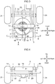
Fig. 1 is a bottom view of a vehicle to which a vehicle body structure of an embodiment is applied. -
Figs. 2A and 2B are perspective views of a tank mounted on the vehicle. -
Fig. 3 is a top view in which the vehicle body structure is viewed from the top. -
Fig. 4 is a rear view illustrating the vehicle body structure (a view taken from an arrow A ofFig. 3 ). -
Fig. 5 is a cross-sectional view illustrating the vehicle body structure (a cross-sectional view taken from a line B-B ofFig. 3 ). -
Fig. 6 is a perspective view illustrating the vehicle body structure. - A vehicle body structure according to an embodiment will be described with reference to the accompanying drawings. The embodiment described below is merely an example and is not intended to exclude various modifications and applications of techniques that have not been described in the following embodiment. Each configuration of the present embodiment can be embodied by various modifications without departing from the spirit. In addition, each configuration may be selected if necessary or may be appropriately combined.
- The vehicle body structure of the present embodiment is applied to a
vehicle 10 illustrated inFig. 1 . Thevehicle 10 is a pick-up truck type SUV (Sport Utility Vehicle) vehicle equipped with a urea SCR system. As the body structure of thevehicle 10, a separate frame structure in which the frame and the vehicle body are separated is employed. On the front side of thevehicle 10 on the frame, a box-like cab (vehicle interior) on which an occupant gets is disposed, and aplatform 11 is disposed on the rear side thereof. - The
vehicle 10 is ordinarily equipped with atank 3 that stores an additive for exhaust purification (for example, an aqueous urea solution, aqueous ammonia solution or the like). The urea SCR system is a kind of exhaust purification systems for purifying nitrogen oxide (NOx) contained in the exhaust gas of the engine. In the urea SCR system of the present embodiment, the aqueous urea solution is injected to the upstream side of a NOx selective reduction catalyst interposed on an exhaust passage, and NOx is reduced to nitrogen on the catalyst, using ammonia generated by the hydrolysis of urea as a reducing agent. This kind of the urea SCR system is widely used in vehicles, working machines, vessels and power plants equipped with a diesel engine or a lean-burn engine. - The
vehicle 10 is provided with a pair ofside members 1 and across member 2 which serve as a frame. Theside members 1 are hollow cylindrical structural members which are disposed at intervals in a vehicle width direction (a left-right direction), and extend in a vehicle length direction (a front-rear direction) of thevehicle 10. Further, thecross member 2 is a structural member which connects the left andright side members 1 in a ladder shape, and are provided at a plurality of positions at intervals in the front-rear direction. The arrangement direction of theside members 1 and thecross member 2 is a substantially horizontal direction. A cab and theplatform 11 of thevehicle 10 are mounted on the frame via a vibration damping mount member. - As illustrated in
Fig. 1 , atank 3, aspare tire 7, aguard bar 8 and abumper 9 are provided on the bottom surface side of theplatform 11 of thevehicle 10. Thespare tire 7 is fixed to aspare tire bracket 19 disposed behind anaxle 22 of arear wheel 21 so as to be attachable and detachable via fixtures 12 (seeFig. 3 ). Thespare tire bracket 19 is a member that is attached to extend between the left andright side members 1. Further, thefixture 12 is a fixing device for fixing thespare tire 7 to thespare tire bracket 19, and is equipped with a mechanism that raises and lowers thespare tire 7 by winding-up and unwinding of a chain. By manually rotating a sprocket around which the chain is wound, the chain is wound up or unwound. - The position of the
spare tire 7 in the front-rear direction is set on the front side of thevehicle 10 as much as possible in a range that does not interfere with theaxle 22 and adifferential unit 23 of therear wheel 21. Further, the position of thespare tire 7 in the left-right direction is set such that a predetermined interval is secured to anexhaust tube 24.Fig. 1 illustrates thevehicle 10 in which theexhaust tube 24 is disposed to be biased to the right side (lower side inFig. 1 ) of a vehicle body center line C, and thespare tire 7 is disposed to be biased to the left side (upper side inFig. 1 ) of the vehicle body center line C by a dimension W. - The
guard bar 8 is a member that extends substantially horizontally toward the left-right direction behind thespare tire 7, and is firmly fixed to each of the left andright side members 1 via abracket 14. The main role of theguard bar 8 is to prevent the penetration into the vehicle body bottom, while absorbing the impact force from the rear part of the vehicle body at the time of contact or collision with another vehicle or an obstacle. Therefore, theguard bar 8 is preferably disposed at a position closer to the rear end of thevehicle 10. In the example illustrated inFig. 1 , thebumper 9 is mounted to arear end panel 20 located at the rear end of theplatform 11, and theguard bar 8 is disposed slightly in front of the bumper 9 (seeFig. 5 ). Each of the both left and right ends of theguard bar 8 is stretched to the outside of the pair ofside members 1 and is stretched to the outside of both of the left and right ends of thebumper 9. As a result, almost the entire rear end of thevehicle 10 is protected by theguard bar 8. - The
tank 3 is a hollow container that stores the aqueous urea solution. As illustrated inFigs. 1 and3 to 6 , thetank 3 is disposed in the upper space of theguard bar 8, behind thespare tire 7 and in front of thebumper 9. Thebumper 9 is disposed at a predetermined interval to therear side 31 of thetank 3. As illustrated inFig. 5 , the height of the bottom surface of thetank 3 is set above the bottom surface of thespare tire 7, and above the lower end side of thebumper 9. Further, the height of the upper surface of thetank 3 is set below the upper surface of theside member 1. Thus, thetank 3 is in a state of being surrounded by thespare tire 7, therear end panel 20, thebumper 9 and theside member 1, and the protection of thetank 3 is improved. - Here, in order to describe the shape of the
tank 3, the part of thetank 3 will be conveniently described by being divided into the laterally-long section 4 and thetriangular section 5. As illustrated inFigs. 2A and 2B , the laterally-long section 4 is a part extending in the left-right direction, and thetriangular section 5 is a part provided at both ends of the laterally-long section 4. The laterally-long section 4 and thetriangular section 5 form a single internal space rather than being internally partitioned. Further, the dimensions in the height direction of the laterally-long section 4 and thetriangular section 5 are substantially constant. A broken line inFigs. 2A and 2B is a virtual line that represents a boundary between the laterally-long section 4 and thetriangular section 5. - The laterally-
long section 4 is a part that is disposed substantially in parallel to theguard bar 8 right above theguard bar 8. The dimension of the laterally-long section 4 in the left-right direction is set to be substantially identical to the width of the pair ofside members 1. As illustrated inFig. 1 , when viewed in the bottom view of thevehicle 10, theguard bar 8 is disposed to overlap the laterally-long section 4. Thus, substantially the entire bottom surface of the laterally-long section 4 is protected by theguard bar 8. On theupper surface 32 of the laterally-long section 4, as illustrated inFigs. 2A and 2B , arecess 15 which is recessed in a groove shape is formed, and anair vent 18 for releasing the pressure at the time of a rise of the internal pressure of thetank 3 is provided. - The shape of the
recess 15 is set to have a size that does not interfere with a detachingtool 13 for rotating the sprocket of thefixture 12, when detaching thespare tire 7 from thespare tire bracket 19. Further, the extending direction of therecess 15 is a direction extending from thefixture 12 of thespare tire 7 to the rear of thevehicle 10. The term "direction extending from thefixture 12 to the rear of thevehicle 10" may be a front-rear direction of thevehicle 10 as illustrated inFig. 3 or may be a direction (a diagonally backward direction) that is slightly inclined from this direction. The direction may be set in accordance with the direction of the sprocket. Thus, as illustrated inFig. 6 , the rod-like detaching tool 13 is inserted to pass through the inner side of therecess 15. Accordingly, it is possible to raise and lower thespare tire 7 without detaching thetank 3, and the workability is improved. - The
triangular section 5 is a part formed by enlarging the dimension in the front-rear direction at each of both ends of the laterally-long section 4. As illustrated inFig. 1 , the shape of thetriangular section 5 when viewed in the bottom view is a shape (for example, a triangular shape) that corresponds to a gap between the circularspare tire 7 and theside member 1. That is, the shape of thetriangular section 5 is set to correspond to the shape of the space interposed between thespare tire 7 and theside member 1. Furthermore, since thespare tire 7 is disposed to be biased to the left side of the vehicle body center line C, the righttriangular section 5 has a shape that is slightly larger than that of the lefttriangular section 5 of thevehicle 10. This makes it possible to use an extra space as a storage space of the aqueous urea solution, thereby saving the space. - As illustrated in
Fig. 2B , asupply module 6 is attached to the bottom surface side of the righttriangular section 5 and the laterally-long section 4 adjacent thereto. Thesupply module 6 is a component obtained by combining various devices for supplying the aqueous urea solution stored in thetank 3 to an exhaust system (for example, a urea water injector provided on the exhaust passage), and is attached to pass through the bottom surface of thetank 3. - In the
supply module 6, a pump for pumping the urea water to the urea water injector, a heater for heating the urea water to a suitable temperature, a filter for removing foreign substances in the urea water, a temperature sensor for detecting the temperature of the urea water, a residual quantity sensor for detecting the tank residual quantity of urea water and the like are equipped. Therefore, a piping material or a pump through which the urea water flows, an electric wiring for driving the heater, a signal line for transmitting the detection signals of the various sensors and the like are connected to thesupply module 6. In the present embodiment, as illustrated inFig. 5 , the layout of thesupply module 6 and theguard bar 8 is set such that the pump for thesupply module 6 is disposed right above theguard bar 8. - On a
floor surface 33 of theplatform 11 of thevehicle 10, a urea water injection port 16 (the water injection port) connected in a state of communicating with the interior of thetank 3 is provided. Further, awater injection tube 17 is connected between the ureawater injection port 16 and thetank 3. Thewater injection tube 17 is a hollow hose for replenishing the aqueous urea solution to the interior of thetank 3. As illustrated inFig. 5 , the position of the ureawater injection port 16 is set at a position corresponding to a part right above thetank 3, of thefloor surface 33 of theplatform 11. Accordingly, the tube length of thewater injection tube 17 is shortened. -
- (1) In the aforementioned vehicle body structure, the
spare tire 7 and theguard bar 8 are fixed to theside member 1, and thetank 3 of the aqueous urea solution is disposed behind thespare tire 7 and above theguard bar 8. In this way, by disposing thetank 3 in a space surrounded by thespare tire 7 and theguard bar 8, it is possible to reduce the possibility of the chipping from the road surface or the contact with the road surface, and it is possible to effectively utilize the free space. Accordingly, it is possible to enhance the protection of thetank 3, while saving the space. Furthermore, since theguard bar 8 is disposed below thetank 3, it is possible to prevent the contact between the bottom surface of thetank 3 and the road surface at the time of running on a step or a rough road.
In particular, because thespare tire 7 is in front of thetank 3, when an external force (such as a rear collision load or a rear-end collision load) is applied from the rear, it is possible to elastically support thetank 3 with thespare tire 7. Further, if thetank 3 is laid out on the spare tire 7 (for example, seeJP 5194543 B1 tank 3, in some cases, the accuracy of the residual quantity of the tank detected by the residual quantity sensor decreases, or the detection itself may not be performed. In contrast, if thetank 3 is laid out behind thespare tire 7, because it is possible to ensure a dimension in the height direction of thetank 3, it is possible to improve the accuracy of the tank residual quantity detected by the residual quantity sensor. - (2) In the aforementioned vehicle body structure, the
tank 3 is disposed above theguard bar 8, behind thespare tire 7 and in front of thebumper 9. Thus, in addition to the aforementioned effects, it is possible to protect therear side 31 of thetank 3 by thebumper 9 and therear end panel 20. Therefore, it is possible to enhance the protection of thetank 3. Since theside member 1 is disposed in the left-right direction of thetank 3, it is also possible to improve the protection of the side surface of thetank 3. - (3) In the aforementioned body structure, as illustrated in
Fig. 1 , the laterally-long section 4 of thetank 3 is disposed to be substantially parallel to theguard bar 8 right above theguard bar 8. Thus, it is possible to protect the bottom of thetank 3 by theguard bar 8 over substantially the entire left-right direction (the vehicle width direction), which makes it possible to further enhance the protection of thetank 3. For example, even when thevehicle 10 tries to climb over a step, thetank 3 does not come into contact with the road surface, and thus, it is possible to prevent deformation or breakage of thetank 3. - (4) As illustrated in
Figs. 2A and 2B , at both of left and right ends of thetank 3, thetriangular sections 5 having a shape corresponding to the triangular space interposed between thespare tire 7 and theside member 1 are provided. In this way, by providing a pair oftriangular sections 5 at both ends of the laterally-long section 4, it is possible to sufficiently secure the volume of thetank 3. Further, because the shape of thetriangular sections 5 is a shape corresponding to the gap between thespare tire 7 and theside member 1 when viewed in the bottom view, it is possible to utilize the space that has not been conventionally utilized, and the space can be further saved. - (5) As illustrated in
Figs. 1 ,2B , and4 , thesupply module 6 equipped with the pump for the urea water is attached to one side close to theexhaust tube 24, of both ends of the laterally-long section 4. Thus, it is possible to warm the aqueous urea solution around the pump by the exhaust heat. Accordingly, it is possible to reliably operate the pump even in an extremely cold region. Further, because the aqueous urea solution is intended to be supplied to the exhaust system, it is possible to shorten the piping length from thesupply module 6 to the urea water injector. - (6) As illustrated in
Figs. 2A, 2B ,3 and6 , therecess 15 is provided on theupper surface 32 of the laterally-long section 4, and its extending direction is a direction extending from thefixture 12 of thespare tire 7 to the rear of thevehicle 10. Thus, it is possible to insert the detachingtool 13 toward thefixture 12 of thespare tire 7 from the rear of thevehicle 10. That is, it becomes possible to raise and lower thespare tire 7 without detaching thetank 3, which makes it possible to improve the workability of the attachment and detachment of thespare tire 7. - (7) As illustrated in
Fig. 5 , the ureawater injection port 16 is provided on thefloor surface 33 of theplatform 11 of thevehicle 10. Accordingly, as compared to the case of providing the ureawater injection port 16 on the side surface of thevehicle 10, it is possible to improve the aesthetics of thevehicle 10. Further, because the position of the ureawater injection port 16 is located right above thetank 3, it is possible to shorten the piping length (the length of the water injection tube 17) from the ureawater injection port 16 to thetank 3. Further, since the ureawater injection port 16 is open upward, the replenishing operation of the aqueous urea solution is facilitated, and it is possible to improve the water injection workability. - While the layout of the
tank 3 in thevehicle 10 of the separate frame structure has been described in the aforementioned embodiment, it is also possible to apply the layout of thetank 3 to the monocoque vehicle. For example, thespare tire 7 and theguard bar 8 are fixed to the frame of the monocoque body, and thetank 3 is disposed in a space surrounded by thespare tire 7 and theguard bar 8. This makes it possible to obtain the same effects as the aforementioned embodiment. - While the aforementioned embodiment illustrates the
vehicle 10 in which thespare tire 7 is disposed to be biased to the left side of thevehicle 10 as illustrated inFig. 1 as an example, the position of thespare tire 7 in the vehicle width direction can be arbitrarily set. Further, the same also applies to the shape of thetank 3, and thetank 3, for example, may have a symmetrical shape in the left-right direction when viewed in a bottom view, and may have a shape biased to one of the right and left from the vehicle body center line C of thevehicle 10. At least, by disposing thetank 3 behind thespare tire 7 and above theguard bar 8, it is possible to obtain the same effects as the aforementioned embodiment. - While the aforementioned embodiment illustrates the
vehicle 10 in which asingle guard bar 8 is provided as an example, the number ofguard bar 8 is arbitrary. For example, a plurality ofguard bars 8 may be disposed in parallel in the front-rear direction in accordance with the size (the dimension in the front-rear direction) of thetank 3. By increasing the area of the bottom surface side of thetank 3 which is covered by theguard bar 8 when viewed in the bottom view, it is possible to further enhance the protection of thetank 3. - While the aforementioned embodiment illustrates the configuration in which the urea
water injection port 16 is provided on thefloor surface 33 of theplatform 11 as an example, the arrangement position of the ureawater injection port 16 is not limited thereto. For example, the ureawater injection port 16 may be provided on the side gate or the rear gate of theplatform 11, and may be provided on the side surface of the vehicle 10 (for example, a position adjacent to an oil supply port). Alternatively, the cap may be attached such that the aqueous urea solution can be directly replenished to the tank. - The invention thus described, it will be obvious that the same may be varied in many ways as defined by the following claims.
-
- 1
- side member (frame)
- 2
- cross member (frame)
- 3
- tank
- 4
- laterally-long section
- 5
- triangular part
- 6
- supply module (pressure pump)
- 7
- spare tire
- 8
- guard bar
- 9
- bumper
- 10
- vehicle
- 11
- platform
- 12
- fixture
- 13
- detaching tool
- 14
- bracket
- 15
- recess
- 16
- urea water injection port (water injection port)
- 17
- water injection tube
- 18
- air vent
- 19
- spare tire bracket
- 20
- rear end panel
- 21
- rear wheel
- 22
- axle
- 23
- differential device
- 24
- exhaust tube
- 31
- rear side of
tank 3 - 32
- upper surface of laterally-
long section 4 - 33
- floor surface of platform 11 (platform floor surface)
- C
- vehicle body center line
Claims (7)
- A vehicle body structure comprising:a frame (1) of a vehicle (10);a spare tire (7) that is fixed to the frame (1);a guard bar (8) that extends in a vehicle width direction behind the spare tire (7), and is fixed to the frame (1); anda tank (3) that is disposed behind the spare tire (7) and above the guard bar (8), and stores an additive for exhaust purification of the vehicle.
- The vehicle body structure according to claim 1, further comprising:a bumper (9) that is disposed at a predetermined interval with respect to a rear side (31) of the tank (3),characterized in that the tank (3) is disposed within a space surrounded by the spare tire (7), the guard bar (8) and the bumper (9).
- The vehicle body structure according to claim 1 or 2, characterized in that the tank (3) has a laterally long section (4) that is disposed to be parallel to the guard bar (8) above the guard bar (8).
- The vehicle body structure according to claim 3, characterized in that the tank (3) has a pair of triangular sections (5) that is formed in a triangular shape corresponding to a gap between the spare tire (7) and the frame (1) when viewed from a bottom and is disposed at both ends of the laterally long section (4).
- The vehicle body structure according to claim 3 or 4, further comprising:a pump (6) for the additive that is attached to one end of two ends of the laterally long section (4), the one end being the one closer to an exhaust pipe (24) of the vehicle, and is disposed above the guard bar (8).
- The vehicle body structure according to any one of claims 3 to 5, further comprising:a fixture (12) that fixes the spare tire (7) to the frame (1); anda recess (15) that is recessed in a groove shape in a direction from the fixture (12) toward the vehicle rear side, on an upper surface (32) of the laterally long section (4).
- The vehicle body structure according to any one of claims 1 to 6, further comprising:a water injection port (16) that is provided on a platform floor surface (33) of the vehicle (10), and is connected in a state of communicating with the interior of the tank (3).
Applications Claiming Priority (1)
| Application Number | Priority Date | Filing Date | Title |
|---|---|---|---|
| JP2015228353A JP6682823B2 (en) | 2015-11-24 | 2015-11-24 | Body structure |
Publications (2)
| Publication Number | Publication Date |
|---|---|
| EP3173274A1 true EP3173274A1 (en) | 2017-05-31 |
| EP3173274B1 EP3173274B1 (en) | 2018-12-26 |
Family
ID=57406081
Family Applications (1)
| Application Number | Title | Priority Date | Filing Date |
|---|---|---|---|
| EP16200485.7A Active EP3173274B1 (en) | 2015-11-24 | 2016-11-24 | Vehicle body structure |
Country Status (2)
| Country | Link |
|---|---|
| EP (1) | EP3173274B1 (en) |
| JP (1) | JP6682823B2 (en) |
Cited By (2)
| Publication number | Priority date | Publication date | Assignee | Title |
|---|---|---|---|---|
| WO2019019441A1 (en) * | 2017-07-26 | 2019-01-31 | Compagnie Plastic Omnium | A vehicle exterior part |
| FR3086633A1 (en) * | 2018-10-02 | 2020-04-03 | Renault S.A.S | REAR PART OF VEHICLE WITH A DURATION TANK |
Families Citing this family (4)
| Publication number | Priority date | Publication date | Assignee | Title |
|---|---|---|---|---|
| JP7185183B2 (en) * | 2018-10-29 | 2022-12-07 | 三菱自動車工業株式会社 | tank protection unit |
| WO2020241231A1 (en) * | 2019-05-28 | 2020-12-03 | 三菱自動車工業株式会社 | Vehicle body structure |
| JP7173323B2 (en) * | 2019-05-28 | 2022-11-16 | 三菱自動車工業株式会社 | body frame |
| WO2025186936A1 (en) * | 2024-03-06 | 2025-09-12 | 三菱自動車工業株式会社 | Vehicle body structure |
Citations (6)
| Publication number | Priority date | Publication date | Assignee | Title |
|---|---|---|---|---|
| US20040142232A1 (en) * | 2000-11-30 | 2004-07-22 | Alex Risca | Space utilization/component integration using blow molding technology |
| JP2008265689A (en) * | 2007-04-25 | 2008-11-06 | Mazda Motor Corp | Reducing agent tank arrangement structure in vehicle |
| JP2009143262A (en) * | 2007-12-11 | 2009-07-02 | Mazda Motor Corp | Vehicle reductant tank arrangement structure |
| JP4826612B2 (en) | 2007-10-12 | 2011-11-30 | マツダ株式会社 | Vehicle exhaust purification device arrangement structure |
| JP4924352B2 (en) | 2007-10-12 | 2012-04-25 | マツダ株式会社 | Vehicle exhaust purification device arrangement structure |
| FR2991647A1 (en) * | 2012-06-08 | 2013-12-13 | Peugeot Citroen Automobiles Sa | Device for remote filling of nitrogen oxide reducing catalyst additive, in interior of boot of vehicle i.e. car, has rigid fixing mechanism on support on part of boot of vehicle, and pipe arranged with maintenance notch for filling of fluid |
-
2015
- 2015-11-24 JP JP2015228353A patent/JP6682823B2/en active Active
-
2016
- 2016-11-24 EP EP16200485.7A patent/EP3173274B1/en active Active
Patent Citations (7)
| Publication number | Priority date | Publication date | Assignee | Title |
|---|---|---|---|---|
| US20040142232A1 (en) * | 2000-11-30 | 2004-07-22 | Alex Risca | Space utilization/component integration using blow molding technology |
| JP2008265689A (en) * | 2007-04-25 | 2008-11-06 | Mazda Motor Corp | Reducing agent tank arrangement structure in vehicle |
| JP5194543B2 (en) | 2007-04-25 | 2013-05-08 | マツダ株式会社 | Reducing agent tank arrangement structure in vehicle |
| JP4826612B2 (en) | 2007-10-12 | 2011-11-30 | マツダ株式会社 | Vehicle exhaust purification device arrangement structure |
| JP4924352B2 (en) | 2007-10-12 | 2012-04-25 | マツダ株式会社 | Vehicle exhaust purification device arrangement structure |
| JP2009143262A (en) * | 2007-12-11 | 2009-07-02 | Mazda Motor Corp | Vehicle reductant tank arrangement structure |
| FR2991647A1 (en) * | 2012-06-08 | 2013-12-13 | Peugeot Citroen Automobiles Sa | Device for remote filling of nitrogen oxide reducing catalyst additive, in interior of boot of vehicle i.e. car, has rigid fixing mechanism on support on part of boot of vehicle, and pipe arranged with maintenance notch for filling of fluid |
Cited By (3)
| Publication number | Priority date | Publication date | Assignee | Title |
|---|---|---|---|---|
| WO2019019441A1 (en) * | 2017-07-26 | 2019-01-31 | Compagnie Plastic Omnium | A vehicle exterior part |
| FR3086633A1 (en) * | 2018-10-02 | 2020-04-03 | Renault S.A.S | REAR PART OF VEHICLE WITH A DURATION TANK |
| EP3632782A1 (en) * | 2018-10-02 | 2020-04-08 | RENAULT s.a.s. | Rear end of a vehicle provided with a urea tank |
Also Published As
| Publication number | Publication date |
|---|---|
| JP6682823B2 (en) | 2020-04-15 |
| JP2017094885A (en) | 2017-06-01 |
| EP3173274B1 (en) | 2018-12-26 |
Similar Documents
| Publication | Publication Date | Title |
|---|---|---|
| EP3173274B1 (en) | Vehicle body structure | |
| US8056671B2 (en) | Exhaust-gas purification device disposition structure of vehicle | |
| EP2949496B1 (en) | Work vehicle | |
| US20160265405A1 (en) | Reducing agent tank module | |
| KR102183434B1 (en) | tractor | |
| CN104564260A (en) | Urea solution apparatus for vehicles | |
| EP3173273B1 (en) | Vehicle body structure | |
| CN102745288B (en) | Riding type vehicle | |
| EP3173276B1 (en) | Vehicle body structure | |
| JP7185183B2 (en) | tank protection unit | |
| JP7173323B2 (en) | body frame | |
| JP7310308B2 (en) | Vehicle urea water tank | |
| JP2015121162A (en) | Vehicle component protection plate | |
| JP7806926B2 (en) | tank | |
| RU2679102C2 (en) | Motor vehicle chassis comprising a tank for storing a pollutant removal agent and corresponding motor vehicle | |
| JP7226540B2 (en) | car body structure | |
| JP6582917B2 (en) | Tank arrangement structure | |
| JP6668882B2 (en) | Additive container | |
| JP7468985B2 (en) | Excavator | |
| JP6862933B2 (en) | Body structure | |
| JP6848536B2 (en) | Body structure | |
| JP6525244B2 (en) | Reductant tank mounting structure | |
| JP6930201B2 (en) | Supply pump |
Legal Events
| Date | Code | Title | Description |
|---|---|---|---|
| PUAI | Public reference made under article 153(3) epc to a published international application that has entered the european phase |
Free format text: ORIGINAL CODE: 0009012 |
|
| STAA | Information on the status of an ep patent application or granted ep patent |
Free format text: STATUS: THE APPLICATION HAS BEEN PUBLISHED |
|
| AK | Designated contracting states |
Kind code of ref document: A1 Designated state(s): AL AT BE BG CH CY CZ DE DK EE ES FI FR GB GR HR HU IE IS IT LI LT LU LV MC MK MT NL NO PL PT RO RS SE SI SK SM TR |
|
| AX | Request for extension of the european patent |
Extension state: BA ME |
|
| STAA | Information on the status of an ep patent application or granted ep patent |
Free format text: STATUS: REQUEST FOR EXAMINATION WAS MADE |
|
| 17P | Request for examination filed |
Effective date: 20171129 |
|
| RBV | Designated contracting states (corrected) |
Designated state(s): AL AT BE BG CH CY CZ DE DK EE ES FI FR GB GR HR HU IE IS IT LI LT LU LV MC MK MT NL NO PL PT RO RS SE SI SK SM TR |
|
| STAA | Information on the status of an ep patent application or granted ep patent |
Free format text: STATUS: EXAMINATION IS IN PROGRESS |
|
| 17Q | First examination report despatched |
Effective date: 20180119 |
|
| GRAP | Despatch of communication of intention to grant a patent |
Free format text: ORIGINAL CODE: EPIDOSNIGR1 |
|
| STAA | Information on the status of an ep patent application or granted ep patent |
Free format text: STATUS: GRANT OF PATENT IS INTENDED |
|
| INTG | Intention to grant announced |
Effective date: 20180627 |
|
| GRAS | Grant fee paid |
Free format text: ORIGINAL CODE: EPIDOSNIGR3 |
|
| GRAJ | Information related to disapproval of communication of intention to grant by the applicant or resumption of examination proceedings by the epo deleted |
Free format text: ORIGINAL CODE: EPIDOSDIGR1 |
|
| GRAL | Information related to payment of fee for publishing/printing deleted |
Free format text: ORIGINAL CODE: EPIDOSDIGR3 |
|
| STAA | Information on the status of an ep patent application or granted ep patent |
Free format text: STATUS: EXAMINATION IS IN PROGRESS |
|
| GRAR | Information related to intention to grant a patent recorded |
Free format text: ORIGINAL CODE: EPIDOSNIGR71 |
|
| STAA | Information on the status of an ep patent application or granted ep patent |
Free format text: STATUS: GRANT OF PATENT IS INTENDED |
|
| GRAA | (expected) grant |
Free format text: ORIGINAL CODE: 0009210 |
|
| STAA | Information on the status of an ep patent application or granted ep patent |
Free format text: STATUS: THE PATENT HAS BEEN GRANTED |
|
| INTC | Intention to grant announced (deleted) | ||
| INTG | Intention to grant announced |
Effective date: 20181115 |
|
| AK | Designated contracting states |
Kind code of ref document: B1 Designated state(s): AL AT BE BG CH CY CZ DE DK EE ES FI FR GB GR HR HU IE IS IT LI LT LU LV MC MK MT NL NO PL PT RO RS SE SI SK SM TR |
|
| REG | Reference to a national code |
Ref country code: GB Ref legal event code: FG4D |
|
| REG | Reference to a national code |
Ref country code: CH Ref legal event code: EP |
|
| REG | Reference to a national code |
Ref country code: AT Ref legal event code: REF Ref document number: 1080926 Country of ref document: AT Kind code of ref document: T Effective date: 20190115 |
|
| REG | Reference to a national code |
Ref country code: DE Ref legal event code: R096 Ref document number: 602016008672 Country of ref document: DE |
|
| REG | Reference to a national code |
Ref country code: IE Ref legal event code: FG4D |
|
| PG25 | Lapsed in a contracting state [announced via postgrant information from national office to epo] |
Ref country code: NO Free format text: LAPSE BECAUSE OF FAILURE TO SUBMIT A TRANSLATION OF THE DESCRIPTION OR TO PAY THE FEE WITHIN THE PRESCRIBED TIME-LIMIT Effective date: 20190326 Ref country code: BG Free format text: LAPSE BECAUSE OF FAILURE TO SUBMIT A TRANSLATION OF THE DESCRIPTION OR TO PAY THE FEE WITHIN THE PRESCRIBED TIME-LIMIT Effective date: 20190326 Ref country code: LT Free format text: LAPSE BECAUSE OF FAILURE TO SUBMIT A TRANSLATION OF THE DESCRIPTION OR TO PAY THE FEE WITHIN THE PRESCRIBED TIME-LIMIT Effective date: 20181226 Ref country code: FI Free format text: LAPSE BECAUSE OF FAILURE TO SUBMIT A TRANSLATION OF THE DESCRIPTION OR TO PAY THE FEE WITHIN THE PRESCRIBED TIME-LIMIT Effective date: 20181226 Ref country code: HR Free format text: LAPSE BECAUSE OF FAILURE TO SUBMIT A TRANSLATION OF THE DESCRIPTION OR TO PAY THE FEE WITHIN THE PRESCRIBED TIME-LIMIT Effective date: 20181226 Ref country code: LV Free format text: LAPSE BECAUSE OF FAILURE TO SUBMIT A TRANSLATION OF THE DESCRIPTION OR TO PAY THE FEE WITHIN THE PRESCRIBED TIME-LIMIT Effective date: 20181226 |
|
| REG | Reference to a national code |
Ref country code: NL Ref legal event code: MP Effective date: 20181226 |
|
| REG | Reference to a national code |
Ref country code: LT Ref legal event code: MG4D |
|
| PG25 | Lapsed in a contracting state [announced via postgrant information from national office to epo] |
Ref country code: SE Free format text: LAPSE BECAUSE OF FAILURE TO SUBMIT A TRANSLATION OF THE DESCRIPTION OR TO PAY THE FEE WITHIN THE PRESCRIBED TIME-LIMIT Effective date: 20181226 Ref country code: RS Free format text: LAPSE BECAUSE OF FAILURE TO SUBMIT A TRANSLATION OF THE DESCRIPTION OR TO PAY THE FEE WITHIN THE PRESCRIBED TIME-LIMIT Effective date: 20181226 Ref country code: AL Free format text: LAPSE BECAUSE OF FAILURE TO SUBMIT A TRANSLATION OF THE DESCRIPTION OR TO PAY THE FEE WITHIN THE PRESCRIBED TIME-LIMIT Effective date: 20181226 Ref country code: GR Free format text: LAPSE BECAUSE OF FAILURE TO SUBMIT A TRANSLATION OF THE DESCRIPTION OR TO PAY THE FEE WITHIN THE PRESCRIBED TIME-LIMIT Effective date: 20190327 |
|
| REG | Reference to a national code |
Ref country code: AT Ref legal event code: MK05 Ref document number: 1080926 Country of ref document: AT Kind code of ref document: T Effective date: 20181226 |
|
| PG25 | Lapsed in a contracting state [announced via postgrant information from national office to epo] |
Ref country code: NL Free format text: LAPSE BECAUSE OF FAILURE TO SUBMIT A TRANSLATION OF THE DESCRIPTION OR TO PAY THE FEE WITHIN THE PRESCRIBED TIME-LIMIT Effective date: 20181226 |
|
| RAP2 | Party data changed (patent owner data changed or rights of a patent transferred) |
Owner name: MITSUBISHI JIDOSHA KOGYO KABUSHIKI KAISHA |
|
| PG25 | Lapsed in a contracting state [announced via postgrant information from national office to epo] |
Ref country code: ES Free format text: LAPSE BECAUSE OF FAILURE TO SUBMIT A TRANSLATION OF THE DESCRIPTION OR TO PAY THE FEE WITHIN THE PRESCRIBED TIME-LIMIT Effective date: 20181226 Ref country code: PL Free format text: LAPSE BECAUSE OF FAILURE TO SUBMIT A TRANSLATION OF THE DESCRIPTION OR TO PAY THE FEE WITHIN THE PRESCRIBED TIME-LIMIT Effective date: 20181226 Ref country code: CZ Free format text: LAPSE BECAUSE OF FAILURE TO SUBMIT A TRANSLATION OF THE DESCRIPTION OR TO PAY THE FEE WITHIN THE PRESCRIBED TIME-LIMIT Effective date: 20181226 Ref country code: IT Free format text: LAPSE BECAUSE OF FAILURE TO SUBMIT A TRANSLATION OF THE DESCRIPTION OR TO PAY THE FEE WITHIN THE PRESCRIBED TIME-LIMIT Effective date: 20181226 Ref country code: PT Free format text: LAPSE BECAUSE OF FAILURE TO SUBMIT A TRANSLATION OF THE DESCRIPTION OR TO PAY THE FEE WITHIN THE PRESCRIBED TIME-LIMIT Effective date: 20190426 |
|
| PG25 | Lapsed in a contracting state [announced via postgrant information from national office to epo] |
Ref country code: IS Free format text: LAPSE BECAUSE OF FAILURE TO SUBMIT A TRANSLATION OF THE DESCRIPTION OR TO PAY THE FEE WITHIN THE PRESCRIBED TIME-LIMIT Effective date: 20190426 Ref country code: SM Free format text: LAPSE BECAUSE OF FAILURE TO SUBMIT A TRANSLATION OF THE DESCRIPTION OR TO PAY THE FEE WITHIN THE PRESCRIBED TIME-LIMIT Effective date: 20181226 Ref country code: EE Free format text: LAPSE BECAUSE OF FAILURE TO SUBMIT A TRANSLATION OF THE DESCRIPTION OR TO PAY THE FEE WITHIN THE PRESCRIBED TIME-LIMIT Effective date: 20181226 Ref country code: RO Free format text: LAPSE BECAUSE OF FAILURE TO SUBMIT A TRANSLATION OF THE DESCRIPTION OR TO PAY THE FEE WITHIN THE PRESCRIBED TIME-LIMIT Effective date: 20181226 Ref country code: SK Free format text: LAPSE BECAUSE OF FAILURE TO SUBMIT A TRANSLATION OF THE DESCRIPTION OR TO PAY THE FEE WITHIN THE PRESCRIBED TIME-LIMIT Effective date: 20181226 |
|
| REG | Reference to a national code |
Ref country code: DE Ref legal event code: R097 Ref document number: 602016008672 Country of ref document: DE |
|
| PG25 | Lapsed in a contracting state [announced via postgrant information from national office to epo] |
Ref country code: DK Free format text: LAPSE BECAUSE OF FAILURE TO SUBMIT A TRANSLATION OF THE DESCRIPTION OR TO PAY THE FEE WITHIN THE PRESCRIBED TIME-LIMIT Effective date: 20181226 Ref country code: AT Free format text: LAPSE BECAUSE OF FAILURE TO SUBMIT A TRANSLATION OF THE DESCRIPTION OR TO PAY THE FEE WITHIN THE PRESCRIBED TIME-LIMIT Effective date: 20181226 |
|
| PLBE | No opposition filed within time limit |
Free format text: ORIGINAL CODE: 0009261 |
|
| STAA | Information on the status of an ep patent application or granted ep patent |
Free format text: STATUS: NO OPPOSITION FILED WITHIN TIME LIMIT |
|
| 26N | No opposition filed |
Effective date: 20190927 |
|
| PG25 | Lapsed in a contracting state [announced via postgrant information from national office to epo] |
Ref country code: SI Free format text: LAPSE BECAUSE OF FAILURE TO SUBMIT A TRANSLATION OF THE DESCRIPTION OR TO PAY THE FEE WITHIN THE PRESCRIBED TIME-LIMIT Effective date: 20181226 |
|
| PG25 | Lapsed in a contracting state [announced via postgrant information from national office to epo] |
Ref country code: TR Free format text: LAPSE BECAUSE OF FAILURE TO SUBMIT A TRANSLATION OF THE DESCRIPTION OR TO PAY THE FEE WITHIN THE PRESCRIBED TIME-LIMIT Effective date: 20181226 |
|
| REG | Reference to a national code |
Ref country code: CH Ref legal event code: PL |
|
| PG25 | Lapsed in a contracting state [announced via postgrant information from national office to epo] |
Ref country code: LU Free format text: LAPSE BECAUSE OF NON-PAYMENT OF DUE FEES Effective date: 20191124 Ref country code: LI Free format text: LAPSE BECAUSE OF NON-PAYMENT OF DUE FEES Effective date: 20191130 Ref country code: CH Free format text: LAPSE BECAUSE OF NON-PAYMENT OF DUE FEES Effective date: 20191130 Ref country code: MC Free format text: LAPSE BECAUSE OF FAILURE TO SUBMIT A TRANSLATION OF THE DESCRIPTION OR TO PAY THE FEE WITHIN THE PRESCRIBED TIME-LIMIT Effective date: 20181226 |
|
| REG | Reference to a national code |
Ref country code: BE Ref legal event code: MM Effective date: 20191130 |
|
| PG25 | Lapsed in a contracting state [announced via postgrant information from national office to epo] |
Ref country code: IE Free format text: LAPSE BECAUSE OF NON-PAYMENT OF DUE FEES Effective date: 20191124 |
|
| PG25 | Lapsed in a contracting state [announced via postgrant information from national office to epo] |
Ref country code: BE Free format text: LAPSE BECAUSE OF NON-PAYMENT OF DUE FEES Effective date: 20191130 |
|
| PG25 | Lapsed in a contracting state [announced via postgrant information from national office to epo] |
Ref country code: CY Free format text: LAPSE BECAUSE OF FAILURE TO SUBMIT A TRANSLATION OF THE DESCRIPTION OR TO PAY THE FEE WITHIN THE PRESCRIBED TIME-LIMIT Effective date: 20181226 |
|
| GBPC | Gb: european patent ceased through non-payment of renewal fee |
Effective date: 20201124 |
|
| PG25 | Lapsed in a contracting state [announced via postgrant information from national office to epo] |
Ref country code: HU Free format text: LAPSE BECAUSE OF FAILURE TO SUBMIT A TRANSLATION OF THE DESCRIPTION OR TO PAY THE FEE WITHIN THE PRESCRIBED TIME-LIMIT; INVALID AB INITIO Effective date: 20161124 Ref country code: MT Free format text: LAPSE BECAUSE OF FAILURE TO SUBMIT A TRANSLATION OF THE DESCRIPTION OR TO PAY THE FEE WITHIN THE PRESCRIBED TIME-LIMIT Effective date: 20181226 |
|
| PG25 | Lapsed in a contracting state [announced via postgrant information from national office to epo] |
Ref country code: GB Free format text: LAPSE BECAUSE OF NON-PAYMENT OF DUE FEES Effective date: 20201124 |
|
| PG25 | Lapsed in a contracting state [announced via postgrant information from national office to epo] |
Ref country code: MK Free format text: LAPSE BECAUSE OF FAILURE TO SUBMIT A TRANSLATION OF THE DESCRIPTION OR TO PAY THE FEE WITHIN THE PRESCRIBED TIME-LIMIT Effective date: 20181226 |
|
| PGFP | Annual fee paid to national office [announced via postgrant information from national office to epo] |
Ref country code: FR Payment date: 20250930 Year of fee payment: 10 |
|
| PGFP | Annual fee paid to national office [announced via postgrant information from national office to epo] |
Ref country code: DE Payment date: 20250930 Year of fee payment: 10 |