EP3173240B1 - System and method for splitting a printer cartridge - Google Patents
System and method for splitting a printer cartridge Download PDFInfo
- Publication number
- EP3173240B1 EP3173240B1 EP16192179.6A EP16192179A EP3173240B1 EP 3173240 B1 EP3173240 B1 EP 3173240B1 EP 16192179 A EP16192179 A EP 16192179A EP 3173240 B1 EP3173240 B1 EP 3173240B1
- Authority
- EP
- European Patent Office
- Prior art keywords
- printer cartridge
- cartridge
- cutting
- scoring
- cutting head
- Prior art date
- Legal status (The legal status is an assumption and is not a legal conclusion. Google has not performed a legal analysis and makes no representation as to the accuracy of the status listed.)
- Not-in-force
Links
- 238000000034 method Methods 0.000 title claims description 20
- 239000003381 stabilizer Substances 0.000 claims description 22
- 230000000087 stabilizing effect Effects 0.000 claims description 2
- 238000004140 cleaning Methods 0.000 description 2
- 238000006073 displacement reaction Methods 0.000 description 2
- 238000010276 construction Methods 0.000 description 1
- 239000000463 material Substances 0.000 description 1
- 238000009987 spinning Methods 0.000 description 1
- 230000001360 synchronised effect Effects 0.000 description 1
Images


Classifications
-
- B—PERFORMING OPERATIONS; TRANSPORTING
- B41—PRINTING; LINING MACHINES; TYPEWRITERS; STAMPS
- B41J—TYPEWRITERS; SELECTIVE PRINTING MECHANISMS, i.e. MECHANISMS PRINTING OTHERWISE THAN FROM A FORME; CORRECTION OF TYPOGRAPHICAL ERRORS
- B41J2/00—Typewriters or selective printing mechanisms characterised by the printing or marking process for which they are designed
- B41J2/005—Typewriters or selective printing mechanisms characterised by the printing or marking process for which they are designed characterised by bringing liquid or particles selectively into contact with a printing material
- B41J2/01—Ink jet
- B41J2/17—Ink jet characterised by ink handling
- B41J2/175—Ink supply systems ; Circuit parts therefor
- B41J2/17503—Ink cartridges
- B41J2/17559—Cartridge manufacturing
-
- B—PERFORMING OPERATIONS; TRANSPORTING
- B26—HAND CUTTING TOOLS; CUTTING; SEVERING
- B26D—CUTTING; DETAILS COMMON TO MACHINES FOR PERFORATING, PUNCHING, CUTTING-OUT, STAMPING-OUT OR SEVERING
- B26D3/00—Cutting work characterised by the nature of the cut made; Apparatus therefor
- B26D3/08—Making a superficial cut in the surface of the work without removal of material, e.g. scoring, incising
-
- B—PERFORMING OPERATIONS; TRANSPORTING
- B26—HAND CUTTING TOOLS; CUTTING; SEVERING
- B26D—CUTTING; DETAILS COMMON TO MACHINES FOR PERFORATING, PUNCHING, CUTTING-OUT, STAMPING-OUT OR SEVERING
- B26D7/00—Details of apparatus for cutting, cutting-out, stamping-out, punching, perforating, or severing by means other than cutting
- B26D7/01—Means for holding or positioning work
- B26D7/02—Means for holding or positioning work with clamping means
-
- B—PERFORMING OPERATIONS; TRANSPORTING
- B26—HAND CUTTING TOOLS; CUTTING; SEVERING
- B26D—CUTTING; DETAILS COMMON TO MACHINES FOR PERFORATING, PUNCHING, CUTTING-OUT, STAMPING-OUT OR SEVERING
- B26D9/00—Cutting apparatus combined with punching or perforating apparatus or with dissimilar cutting apparatus
-
- G—PHYSICS
- G03—PHOTOGRAPHY; CINEMATOGRAPHY; ANALOGOUS TECHNIQUES USING WAVES OTHER THAN OPTICAL WAVES; ELECTROGRAPHY; HOLOGRAPHY
- G03G—ELECTROGRAPHY; ELECTROPHOTOGRAPHY; MAGNETOGRAPHY
- G03G15/00—Apparatus for electrographic processes using a charge pattern
- G03G15/06—Apparatus for electrographic processes using a charge pattern for developing
- G03G15/08—Apparatus for electrographic processes using a charge pattern for developing using a solid developer, e.g. powder developer
- G03G15/0894—Reconditioning of the developer unit, i.e. reusing or recycling parts of the unit, e.g. resealing of the unit before refilling with toner
-
- G—PHYSICS
- G03—PHOTOGRAPHY; CINEMATOGRAPHY; ANALOGOUS TECHNIQUES USING WAVES OTHER THAN OPTICAL WAVES; ELECTROGRAPHY; HOLOGRAPHY
- G03G—ELECTROGRAPHY; ELECTROPHOTOGRAPHY; MAGNETOGRAPHY
- G03G21/00—Arrangements not provided for by groups G03G13/00 - G03G19/00, e.g. cleaning, elimination of residual charge
- G03G21/16—Mechanical means for facilitating the maintenance of the apparatus, e.g. modular arrangements
- G03G21/18—Mechanical means for facilitating the maintenance of the apparatus, e.g. modular arrangements using a processing cartridge, whereby the process cartridge comprises at least two image processing means in a single unit
- G03G21/1803—Arrangements or disposition of the complete process cartridge or parts thereof
- G03G21/181—Manufacturing or assembling, recycling, reuse, transportation, packaging or storage
Definitions
- the present invention relates to remanufactured printer cartridges, and more specifically, splitting, cutting, or opening, a printer cartridge for remanufacturing purposes.
- printer cartridges are split opened to provide access to the inside of the cartridge. Once opened, parts of the printer cartridge can be cleaned or replaced.
- printer cartridges are opened using a spinning saw blade (e.g., a circular saw) that saws through a portion of the printer cartridge.
- a spinning saw blade e.g., a circular saw
- Such method and device are for instance described in US patent number 5,407,518 , which describes cutting away the outer edges of a gasket of a toner cartridge in order to separate certain parts thereof.
- Such a method is not only dangerous for an operator, but also results in printer cartridge material being discharge into the surrounding atmosphere.
- the invention provides a system for splitting a printer cartridge.
- the system includes a cartridge holder, a cutting head, and a conveyor.
- the cartridge holder includes a receiver for receiving the printer cartridge, and a clamp for securing the printer cartridge in the receiver.
- the cutting head includes an idling cutting wheel configured to split the printer cartridge.
- the conveyor provides relative movement between the secured printer cartridge and the cutting head to affect splitting of the printer cartridge.
- the invention provides a method of splitting a printer cartridge.
- the method includes receiving the printer cartridge into a receiver of a cartridge holder.
- the method further includes securing the printer cartridge into the receiver via a clamp of the cartridge holder.
- the method further includes splitting the printer cartridge via an idling cutting wheel of a cutting head.
- the method further includes providing relative movement between the secured printer cartridge and the idling cutting wheel to affect splitting of the printer cartridge.
- the invention provides a system for splitting a printer cartridge.
- the system includes a base, a cutting head coupled to the base, a conveyor coupled to the base, and a cartridge holder movably coupled to the conveyor.
- the cutting head includes an idling cutting wheel.
- the cartridge holder is configured to receive the printer cartridge and move the printer cartridge toward the idling cutting wheel to affect splitting of the printer cartridge by the idling cutting wheel.
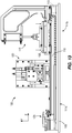
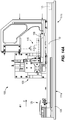
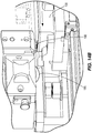
- Figs. 1-3 illustrate a system 100 for splitting, or cutting, a printer cartridge according to one embodiment of the invention.
- the system 100 includes a base 105, a conveyor 110, a printer cartridge holder, or cartridge holder, 115, a cutting head 120, and a cartridge splitter 125.
- the conveyor 110, cutting head 120, and cartridge splitter 125 are coupled to the base 105.
- the cartridge holder 115 is movably coupled to the conveyor 110 and is configured to move in a latitudinal direction, represented as the x-axis.
- the cartridge holder 115 is configured to receive and secure a printer cartridge 130 and provide relative movement between the secured printer cartridge 130 and the cutting head 120, in the latitudinal direction, to affect splitting, or cutting, of the printer cartridge 130. Once split, the inside of the printer cartridge 130 can be accessed for cleaning replacement of parts.
- the base 105 is configured to support the conveyor 110, the cutting head 120, and the cartridge splitter 125.
- the conveyor 110 includes a first end 111a, a second end 111b, a track 112 and an actuator 113.
- the track 112 is a slide, such as but not limited to, a ball slide or a linear ball slide.
- the actuator 113 is a hydraulic actuator.
- the actuator 113 is a motor, such as but not limited to, an alternating-current (AC) motor, a direct-current (DC) motor, a stepper motor, a synchronous motor, or a switched-reluctance motor.
- AC alternating-current
- DC direct-current
- stepper motor a synchronous motor
- switched-reluctance motor a motor that switches-reluctance motor.
- Figs. 4-6 illustrate the cartridge holder 115 according to some embodiments.
- Fig. 4 illustrates a perspective view of the cartridge holder 115 without the printer cartridge 130.
- the cartridge holder 115 includes a cartridge holder base 135, a receiver 140, and a clamp 145.
- the cartridge holder base 135 movably couples the receiver 140 and the clamp 145 to the conveyor 110.
- the receiver 140 includes a recess, or nest, 150 configured to receive the printer cartridge 130.
- the clamp 145 is movably coupled to the cartridge holder base 135 and is configured to move in a longitudinal direction, represented as the y-axis (e.g., perpendicular to the direction of movement of the cartridge holder 115 along the conveyor 110).
- the clamp 145 is configured to be placed in an unclamped position (illustrated in Figs. 4 and 5 ), in which the printer cartridge 130 is unsecured, and a clamped position (illustrated in Fig. 6 ), in which the printer cartridge 130 is secured within the recess 150 of the receiver 140.
- the clamp 145 is rotatably coupled to the cartridge holder base 135 via a pivot 155.
- the pivot 155 is configured to compensate for angular displacement of the printer cartridge 130. In some embodiments, the angular displacement results from inconsistencies or irregularities of the printer cartridge.
- Fig. 7 illustrates a bottom view of the clamp 145 according to one embodiment.
- the clamp 145 includes a clamp pad 160.
- the clamp pad 160 When in the clamped position, the clamp pad 160 is in contact with the printer cartridge 130. In some embodiments, such as illustrated in Fig. 7 , the clamp pad 160 is in contact with an outer edge of the printer cartridge 130.
- Figs. 8 and 9 illustrate the cutting head 120 of the system 100 according to some embodiments.
- the cutting head 120 includes a cutting head base 165, a scorer and cutting assembly 170, and a stabilizer receiver 175.
- the cutting head base 165 couples the scorer and cutting assembly 170 and the stabilizer receiver 175 to the base 105.
- the scorer and cutting assembly 170 includes a scorer 180, a cutting wheel 185, and a stabilizer 190.
- the scorer and cutting assembly 170 is movably coupled to the cutting head base 165 and is configured to move in a longitudinal direction (e.g., along the y-axis) from an unengaged position (illustrated in Fig. 9 ) to an engaged position (illustrated in Fig. 13 ).
- the scorer 180 is coupled to the scorer and cutting assembly 170 in a fixed manner. When the scorer and cutting assembly 170 is in the engaged position, the scorer 180 is configured to score a scoring path 192 ( Fig. 15B ) into the printer cartridge 130 as the printer cartridge 130, contained within the cartridge holder 115, moves along the conveyor 110.
- the scorer 180 includes at least one scoring blade 195a for scoring the scoring path 192.
- the cutting wheel 185 is rotatably coupled to the scorer and cutting assembly 170 in an idle manner (e.g., the cutting wheel 185 freely spins).
- the cutting wheel 185 is configured to cut, or split, the printer cartridge 130 along the scoring path 192 ( Fig. 15B ) created by the scorer 180 as the printer cartridge 130, contained within the cartridge holder 115, moves along the conveyor 110.
- the stabilizer 190 along with the stabilizer receiver 175, are configured to stabilize the scorer and cutting assembly 170 when in the engage position. Stabilizing the scorer and cutting assembly 170 promotes a substantially straight split, or cut, in the printer cartridge 130.
- the stabilizer receiver 175 receives the stabilizer 190.
- the stabilizer 190 comes into contact with a cutting-depth adjuster 200.
- the cutting-depth adjuster 200 is configured to adjust a scoring, and/or cutting, depth of the scorer and cutting assembly 170.
- the cutting-depth adjuster 200 includes a nut and a bolt that may be manually adjusted by an operator to adjust the cutting depth.
- the scorer and cutting assembly 170 further includes a cutting wheel lock 205.
- the cutting wheel lock 205 is configured to lock or prevent the cutting wheel 185 from freely rotating. Once locked, the cutting wheel 185 may be removed or replaced after removing a cutting wheel cover 210.
- Fig. 10 illustrates the scorer 180 according to some embodiments of the invention.
- the scorer 180 includes a plurality of scoring blades 195a-195d.
- the scorer 180 may be rotated to place at least one of the scoring blades 195a-195d into the scoring position.
- the scorer 180 can be rotated such that a non-deteriorated scoring blade is placed into the scoring position.
- Fig. 11 illustrates the scoring blade 195 of the scorer 180 and the cutting wheel 185, according to one embodiment of the invention.
- the scoring blade 195 has a scoring blade angle 220 and the cutting wheel 185 has a cutting blade angle 225.
- the scoring blade angle 220 and the cutting blade angle 225 are substantially similar.
- the scoring angle 220 and the cutting blade angle 225 may be different.
- Fig. 12 illustrates a perspective view of the cartridge splitter 125.
- the cartridge splitter 125 is movably coupled (e.g., configured to move in a latitudinal direction) to the base 105 and includes a splitter edge 230.
- the splitter edge 230 is configured to split the printer cartridge 130 at an angle perpendicular to the scoring path 192.
- the printer cartridge 130 is locked into position at the first end 111a of the conveyor 110, near the cartridge splitter 125.
- the splitter edge 230 is then inserted into the printer cartridge 130 to affect splitting of the printer cartridge at an angle perpendicular to the scoring path 192.
- Figs. 13-17 illustrate an exemplary operation of the system 100.
- the cartridge holder 115 moves along the conveyor 110 toward the cutting head 120.
- the printer cartridge 130 first comes into contact with the scoring blade 195 of the scorer 180.
- the scoring path 192 is scored into the printer cartridge 130.
- the printer cartridge 130 next comes into contact with the cutting wheel 185.
- the cutting wheel 185 splits, or cuts, the printer cartridge 130 along the scoring path 192.
- the printer cartridge 130 is then locked into position at the first end 111a of the conveyor 110 and the splitter edge 230 is inserted into the printer cartridge 130 to affect splitting of the printer cartridge at an angle perpendicular to the scoring path 192.
- Figs. 18-20 illustrate a side view of the printer cartridge 130 in various stages of being split open.
- Fig. 18 illustrates the printer cartridge 130 after being split, or cut, by the cutting wheel 185.
- Fig. 19 illustrates the printer cartridge 130 after being split by the splitter edge 230 in a direction perpendicular the scoring path 192.
- the scoring path 192 is substantially adjacent to an internal support wall 235 of the printer cartridge 130.
- the printer cartridge 130 is split adjacent to the internal support wall 235.
- Fig. 20 illustrates the printer cartridge 130 having a portion 240 removed to provide access to the inside of the printer cartridge 130 for cleaning and part replacement purposes.
- the cutting head 120 is movably coupled to the conveyor 110, while the cartridge holder 115 is stationary. In such an embodiments, the cutting head 120 moves toward the cartridge holder 115 to affect splitting, or cutting, of the printer cartridge 130.
- the invention provides, among other things, a system and method for splitting a printer cartridge.
- Various features and advantages of the invention are set forth in the following claims.
Landscapes
- Engineering & Computer Science (AREA)
- Life Sciences & Earth Sciences (AREA)
- Forests & Forestry (AREA)
- Mechanical Engineering (AREA)
- Manufacturing & Machinery (AREA)
- Sustainable Development (AREA)
- Physics & Mathematics (AREA)
- General Physics & Mathematics (AREA)
- Computer Vision & Pattern Recognition (AREA)
- Handling Of Sheets (AREA)
Description
- The present invention relates to remanufactured printer cartridges, and more specifically, splitting, cutting, or opening, a printer cartridge for remanufacturing purposes.
- During remanufacturing, printer cartridges are split opened to provide access to the inside of the cartridge. Once opened, parts of the printer cartridge can be cleaned or replaced. Traditionally, printer cartridges are opened using a spinning saw blade (e.g., a circular saw) that saws through a portion of the printer cartridge. Such method and device are for instance described in
US patent number 5,407,518 , which describes cutting away the outer edges of a gasket of a toner cartridge in order to separate certain parts thereof. Such a method is not only dangerous for an operator, but also results in printer cartridge material being discharge into the surrounding atmosphere. - In one embodiment, the invention provides a system for splitting a printer cartridge. The system includes a cartridge holder, a cutting head, and a conveyor. The cartridge holder includes a receiver for receiving the printer cartridge, and a clamp for securing the printer cartridge in the receiver. The cutting head includes an idling cutting wheel configured to split the printer cartridge. The conveyor provides relative movement between the secured printer cartridge and the cutting head to affect splitting of the printer cartridge.
- In another embodiment, the invention provides a method of splitting a printer cartridge. The method includes receiving the printer cartridge into a receiver of a cartridge holder. The method further includes securing the printer cartridge into the receiver via a clamp of the cartridge holder. The method further includes splitting the printer cartridge via an idling cutting wheel of a cutting head. The method further includes providing relative movement between the secured printer cartridge and the idling cutting wheel to affect splitting of the printer cartridge.
- In another embodiment, the invention provides a system for splitting a printer cartridge. The system includes a base, a cutting head coupled to the base, a conveyor coupled to the base, and a cartridge holder movably coupled to the conveyor. The cutting head includes an idling cutting wheel. The cartridge holder is configured to receive the printer cartridge and move the printer cartridge toward the idling cutting wheel to affect splitting of the printer cartridge by the idling cutting wheel.
- Other aspects of the invention will become apparent by consideration of the detailed description and accompanying drawings.
-
-
Fig. 1 is a perspective view of a system for splitting a printer cartridge according to one embodiment of the invention. -
Fig. 2 is a perspective view of the system ofFig. 1 containing the printer cartridge. -
Fig. 3 is a front view of the system ofFig. 1 containing the printer cartridge. -
Fig. 4 is a perspective view of a cartridge holder of the system ofFig. 1 without the printer cartridge. -
Fig. 5 is a perspective view of the cartridge holder ofFig. 4 containing the printer cartridge and in an unclamped position. -
Fig. 6 is a perspective view of the cartridge holder ofFig. 4 containing the printer cartridge and in a clamped position. -
Fig. 7 is a bottom view of a clamp of the cartridge holder ofFig. 4 . -
Fig. 8 is an exploded perspective view of a cutting head of the system ofFig. 1 . -
Fig. 9 is a front view of the cutting head ofFig. 8 . -
Fig. 10 is a front view of a scorer of the cutting head ofFig. 8 . -
Fig. 11 is a front view illustrating a scoring blade angle of the scorer ofFig. 10 and a cutting blade angle of a cutting wheel of the cutting head ofFig. 8 . -
Fig. 12 is a perspective view of a cartridge splitter of the system ofFig. 1 . -
Fig. 13 is a front view of the system ofFig. 1 with the cartridge holder in a clamped position and the cutting head in an engaged position. -
Fig. 14A is a front view of the system ofFig. 1 with the clamp of the cartridge holder removed for illustrative purposes and the printer cartridge in a scoring position. -
Fig. 14B is a perspective view of the printer cartridge in the scoring position. -
Fig. 15A is a front view of the system ofFig. 1 with the clamp of the cartridge holder removed for illustrative purposes and the printer cartridge in a first cutting position. -
Fig. 15B is a perspective view of the printer cartridge in the first cutting position. -
Fig. 16A is a front view of the system ofFig. 1 with the clamp of the cartridge holder removed for illustrative purposes and the printer cartridge in a second cutting position -
Fig. 16B is a perspective view of the printer cartridge in the second cutting position. -
Fig. 17 is a perspective view of the system ofFig. 1 with the clamp of the cartridge holder removed for illustrative purposes after the printer cartridge has been cut by the cutting head. -
Fig. 18 is a side view of the printer cartridge after being cut by the cutting head ofFig. 8 . -
Fig. 19 is a side view of the printer cartridge after being split by the cartridge splitter ofFig. 12 . -
Fig. 20 is a side view of the printer cartridge having a portion removed to provide access to the inside of the printer cartridge. - Before any embodiments of the invention are explained in detail, it is to be understood that the invention is not limited in its application to the details of construction and the arrangement of components set forth in the following description or illustrated in the following drawings. The invention is capable of other embodiments and of being practiced or of being carried out in various ways.
-
Figs. 1-3 illustrate asystem 100 for splitting, or cutting, a printer cartridge according to one embodiment of the invention. Thesystem 100 includes abase 105, aconveyor 110, a printer cartridge holder, or cartridge holder, 115, acutting head 120, and acartridge splitter 125. Theconveyor 110,cutting head 120, andcartridge splitter 125 are coupled to thebase 105. Thecartridge holder 115 is movably coupled to theconveyor 110 and is configured to move in a latitudinal direction, represented as the x-axis. Thecartridge holder 115 is configured to receive and secure aprinter cartridge 130 and provide relative movement between the securedprinter cartridge 130 and thecutting head 120, in the latitudinal direction, to affect splitting, or cutting, of theprinter cartridge 130. Once split, the inside of theprinter cartridge 130 can be accessed for cleaning replacement of parts. - The
base 105 is configured to support theconveyor 110, thecutting head 120, and thecartridge splitter 125. Theconveyor 110 includes afirst end 111a, asecond end 111b, atrack 112 and anactuator 113. Thetrack 112, along with theactuator 113, moves thecartridge holder 115 in the latitudinal direction. In some embodiments, thetrack 112 is a slide, such as but not limited to, a ball slide or a linear ball slide. In some embodiments, theactuator 113 is a hydraulic actuator. In other embodiments, theactuator 113 is a motor, such as but not limited to, an alternating-current (AC) motor, a direct-current (DC) motor, a stepper motor, a synchronous motor, or a switched-reluctance motor. -
Figs. 4-6 illustrate thecartridge holder 115 according to some embodiments.Fig. 4 illustrates a perspective view of thecartridge holder 115 without theprinter cartridge 130. Thecartridge holder 115 includes acartridge holder base 135, areceiver 140, and aclamp 145. Thecartridge holder base 135 movably couples thereceiver 140 and theclamp 145 to theconveyor 110. Thereceiver 140 includes a recess, or nest, 150 configured to receive theprinter cartridge 130. - The
clamp 145 is movably coupled to thecartridge holder base 135 and is configured to move in a longitudinal direction, represented as the y-axis (e.g., perpendicular to the direction of movement of thecartridge holder 115 along the conveyor 110). Theclamp 145 is configured to be placed in an unclamped position (illustrated inFigs. 4 and 5 ), in which theprinter cartridge 130 is unsecured, and a clamped position (illustrated inFig. 6 ), in which theprinter cartridge 130 is secured within therecess 150 of thereceiver 140. Theclamp 145 is rotatably coupled to thecartridge holder base 135 via apivot 155. Thepivot 155 is configured to compensate for angular displacement of theprinter cartridge 130. In some embodiments, the angular displacement results from inconsistencies or irregularities of the printer cartridge. -
Fig. 7 illustrates a bottom view of theclamp 145 according to one embodiment. In such an embodiment, theclamp 145 includes aclamp pad 160. When in the clamped position, theclamp pad 160 is in contact with theprinter cartridge 130. In some embodiments, such as illustrated inFig. 7 , theclamp pad 160 is in contact with an outer edge of theprinter cartridge 130. -
Figs. 8 and 9 illustrate the cuttinghead 120 of thesystem 100 according to some embodiments. The cuttinghead 120 includes a cuttinghead base 165, a scorer and cuttingassembly 170, and astabilizer receiver 175. The cuttinghead base 165 couples the scorer and cuttingassembly 170 and thestabilizer receiver 175 to thebase 105. - The scorer and cutting
assembly 170 includes ascorer 180, acutting wheel 185, and astabilizer 190. The scorer and cuttingassembly 170 is movably coupled to the cuttinghead base 165 and is configured to move in a longitudinal direction (e.g., along the y-axis) from an unengaged position (illustrated inFig. 9 ) to an engaged position (illustrated inFig. 13 ). - The
scorer 180 is coupled to the scorer and cuttingassembly 170 in a fixed manner. When the scorer and cuttingassembly 170 is in the engaged position, thescorer 180 is configured to score a scoring path 192 (Fig. 15B ) into theprinter cartridge 130 as theprinter cartridge 130, contained within thecartridge holder 115, moves along theconveyor 110. Thescorer 180 includes at least onescoring blade 195a for scoring thescoring path 192. - The
cutting wheel 185 is rotatably coupled to the scorer and cuttingassembly 170 in an idle manner (e.g., thecutting wheel 185 freely spins). When the scorer and cuttingassembly 170 is in the engaged position, thecutting wheel 185 is configured to cut, or split, theprinter cartridge 130 along the scoring path 192 (Fig. 15B ) created by thescorer 180 as theprinter cartridge 130, contained within thecartridge holder 115, moves along theconveyor 110. - The
stabilizer 190, along with thestabilizer receiver 175, are configured to stabilize the scorer and cuttingassembly 170 when in the engage position. Stabilizing the scorer and cuttingassembly 170 promotes a substantially straight split, or cut, in theprinter cartridge 130. When the scorer and cuttingassembly 170 is in the engaged position, thestabilizer receiver 175 receives thestabilizer 190. When received by thestabilizer receiver 175, thestabilizer 190 comes into contact with a cutting-depth adjuster 200. The cutting-depth adjuster 200 is configured to adjust a scoring, and/or cutting, depth of the scorer and cuttingassembly 170. In some embodiments, the cutting-depth adjuster 200 includes a nut and a bolt that may be manually adjusted by an operator to adjust the cutting depth. - In some embodiments, the scorer and cutting
assembly 170 further includes acutting wheel lock 205. Thecutting wheel lock 205 is configured to lock or prevent thecutting wheel 185 from freely rotating. Once locked, thecutting wheel 185 may be removed or replaced after removing acutting wheel cover 210. -
Fig. 10 illustrates thescorer 180 according to some embodiments of the invention. In such an embodiment, thescorer 180 includes a plurality ofscoring blades 195a-195d. By removing a scorer cover 215 (Fig. 8 ), thescorer 180 may be rotated to place at least one of thescoring blades 195a-195d into the scoring position. Thus, in such an embodiment, when at least one of thescoring blades 195a-195d deteriorates, thescorer 180 can be rotated such that a non-deteriorated scoring blade is placed into the scoring position. -
Fig. 11 illustrates thescoring blade 195 of thescorer 180 and thecutting wheel 185, according to one embodiment of the invention. In such an embodiment, thescoring blade 195 has ascoring blade angle 220 and thecutting wheel 185 has acutting blade angle 225. In such an embodiment, thescoring blade angle 220 and thecutting blade angle 225 are substantially similar. However, in other embodiments, thescoring angle 220 and thecutting blade angle 225 may be different. -
Fig. 12 illustrates a perspective view of thecartridge splitter 125. Thecartridge splitter 125 is movably coupled (e.g., configured to move in a latitudinal direction) to thebase 105 and includes asplitter edge 230. Thesplitter edge 230 is configured to split theprinter cartridge 130 at an angle perpendicular to thescoring path 192. In operation, after theprinter cartridge 130 is cut by thecutting wheel 185, theprinter cartridge 130 is locked into position at thefirst end 111a of theconveyor 110, near thecartridge splitter 125. Thesplitter edge 230 is then inserted into theprinter cartridge 130 to affect splitting of the printer cartridge at an angle perpendicular to thescoring path 192. -
Figs. 13-17 illustrate an exemplary operation of thesystem 100. As illustrated inFig. 13 , after theprinter cartridge 130 is secured within thecartridge holder 115, thecartridge holder 115 moves along theconveyor 110 toward the cuttinghead 120. As theprinter cartridge 130 moves toward the cuttinghead 120, theprinter cartridge 130 first comes into contact with thescoring blade 195 of thescorer 180. As theprinter cartridge 130 continues to move along theconveyor 110, via thecartridge holder 115, the scoringpath 192 is scored into theprinter cartridge 130. Theprinter cartridge 130 next comes into contact with thecutting wheel 185. As theprinter cartridge 130 continues to move along theconveyor 110, via thecartridge holder 115, thecutting wheel 185 splits, or cuts, theprinter cartridge 130 along the scoringpath 192. As discussed above, theprinter cartridge 130 is then locked into position at thefirst end 111a of theconveyor 110 and thesplitter edge 230 is inserted into theprinter cartridge 130 to affect splitting of the printer cartridge at an angle perpendicular to thescoring path 192. -
Figs. 18-20 illustrate a side view of theprinter cartridge 130 in various stages of being split open.Fig. 18 illustrates theprinter cartridge 130 after being split, or cut, by thecutting wheel 185.Fig. 19 illustrates theprinter cartridge 130 after being split by thesplitter edge 230 in a direction perpendicular thescoring path 192. As illustrated, the scoringpath 192 is substantially adjacent to aninternal support wall 235 of theprinter cartridge 130. Thus, theprinter cartridge 130 is split adjacent to theinternal support wall 235.Fig. 20 illustrates theprinter cartridge 130 having aportion 240 removed to provide access to the inside of theprinter cartridge 130 for cleaning and part replacement purposes. - In another embodiment, the cutting
head 120 is movably coupled to theconveyor 110, while thecartridge holder 115 is stationary. In such an embodiments, the cuttinghead 120 moves toward thecartridge holder 115 to affect splitting, or cutting, of theprinter cartridge 130. - Thus, the invention provides, among other things, a system and method for splitting a printer cartridge. Various features and advantages of the invention are set forth in the following claims.
-
- 1. The system of claim 4, wherein the scorer includes a plurality of scoring blades, each scoring blade being substantially similar, the scorer adjustable in the cutting head to position one of the scoring blades in a scoring position.
- 2. The system of
claim 1, wherein the clamp includes a pivotable clamp member configured to accommodate irregularities in the printer cartridge and to secure the printer cartridge in the receiver. - 3. The method of claim 12, wherein the step of securing the printer cartridge includes securing the printer cartridge with a pivotable clamp member configured to accommodate irregularities in the printer cartridge.
- 4. A system for splitting a printer cartridge, the system comprising:
- a base;
- a cutting head coupled to the base, the cutting head including an idling cutting wheel;
- a conveyor coupled to the base; and
- a cartridge holder movably coupled to the conveyor, the cartridge holder configured to receive the printer cartridge and move the printer cartridge toward the idling cutting wheel to affect splitting of the printer cartridge by the idling cutting wheel.
- 5. The system of embodiment 4, wherein the cutting head is moveable in a direction perpendicular to the conveyor and is configured to be in an engaged position and an unengaged position.
- 6. The system of embodiment 4, further comprising a scorer having a scoring blade configured to score a scoring path into the printer cartridge.
- 7. The system of embodiment 6, wherein the cutting head further includes the scorer.
- 8. The system of embodiment 6, wherein a scoring depth of the scoring blade is adjustable relative to the cutting wheel.
- 9. The system of embodiment 6, wherein the scoring path is scored into the printer cartridge prior to the printer cartridge being split by the cutting wheel.
- 10. The system of embodiment 6, wherein a scoring blade angle of the scoring blade is substantially similar to a cutting blade angle of the cutting wheel.
- 11. The system of embodiment 6, wherein the scorer includes a plurality of scoring blades, each scoring blade being substantially similar, the scorer adjustable in the cutting head to position one of the scoring blades in a scoring position.
- 12. The system of embodiment 4, further comprising a stabilizer and a stabilizer receiver coupled to the base, wherein the stabilizer is received by the stabilizer receiver when the cutting head is in an engaged position.
- 13. The system of embodiment 12, wherein a cutting depth of the cutting head is adjustable via the stabilizer receiver.
- 14. The system of embodiment 4, wherein the cutting head further includes a cutting wheel lock configured to prevent the cutting wheel from idling.
- 15. The system of embodiment 4, wherein the clamp includes a pivotable clamp member configured to accommodate irregularities in the printer cartridge and to secure the printer cartridge in the receiver.
Claims (20)
- A system (100) for splitting a printer cartridge (130), the system comprising:a cartridge holder (115) includinga receiver (140) for receiving the printer cartridge (130), anda clamp (145) for securing the printer cartridge (130) in the receiver (140);a cutting head (120) including an idling cutting wheel (185) configured to split the printer cartridge (130); anda conveyor (110) providing relative movement between the cartridge holder (115) and the cutting head (120) to affect splitting of the printer cartridge (130).
- The system of claim 1, wherein the cartridge holder (115) is configured to move along the conveyor (110) toward the cutting head (120).
- The system of claim 2, wherein the cutting head (120) is moveable in a direction perpendicular to the conveyor (110) and is configured to be in an engaged position or an unengaged position.
- The system of claim 1, further comprising a scorer (180) having a scoring blade (195)configured to score a scoring path (192) into the printer cartridge (130).
- The system of claim 4, wherein the cutting head (120) further includes the scorer (180).
- The system of claim 4, wherein a scoring depth of the scoring blade (195) is adjustable relative to the cutting wheel (185).
- The system of claim 4, wherein the scoring path (192) is scored into the printer cartridge (130) prior to the printer cartridge (130) being split by the cutting wheel (185).
- The system of claim 4, wherein a scoring blade angle (220) of the scoring blade (195) is substantially similar to a cutting blade angle (225) of the cutting wheel (185).
- The system of claim 1, further comprising a stabilizer (190) and a stabilizer receiver (175), wherein the stabilizer (190) is received by the stabilizer receiver (175) when the cutting head (120) is in an engaged position.
- The system of claim 9, wherein a cutting depth of the cutting head (120) is adjustable via the stabilizer receiver (175).
- The system of claim 1, wherein the cutting head (120) further includes a cutting wheel lock (205) configured to prevent the cutting wheel (185) from idling.
- A method of splitting a printer cartridge (130), the method comprising:receiving the printer cartridge (130) into a receiver (140) of a cartridge holder (115);securing the printer cartridge (130) into the receiver (140) via a clamp (145) of the cartridge holder (115);splitting the printer cartridge (130) via an idling cutting wheel (185) of a cutting head (120); andproviding relative movement between the secured printer cartridge (130) and the idling cutting wheel (185) to affect splitting of the printer cartridge (130).
- The method of claim 12, wherein the step of providing relative movement between the secured printer cartridge (130) and the idling cutting wheel (185) includes moving the cartridge holder (115) along a conveyor (110) toward the cutting head (120).
- The method of claim 12, further comprising moving the cutting head (120) from an unengaged position to an engaged position.
- The method of claim 12, further comprising scoring the printer cartridge (130) via a scorer (180).
- The method of claim 15, wherein the step of scoring the printer cartridge (130) further includes the scorer (180) having a scoring blade (195).
- The method of claim 15, wherein scoring the printer cartridge (130) includes scoring a scoring path (192) in the printer cartridge (130) and wherein splitting the printer cartridge (130) via the idling cutting wheel (185) includes splitting the printer cartridge (130) along the scoring path (192).
- The method of claim 12, further comprising stabilizing the cutting head (120) via a stabilizer (190) being received by a stabilizer receiver (175) when the cutting head (120) is in an engaged position.
- The method of claim 18, further comprising adjusting the cutting depth of the cutting head (120) via the stabilizer receiver (175).
- The method of claim 12, wherein splitting the printer cartridge (130) includes splitting the printer cartridge (130) along a scoring path (192) that is substantially adjacent to an internal support wall (235) of the printer cartridge (130).
Applications Claiming Priority (1)
| Application Number | Priority Date | Filing Date | Title |
|---|---|---|---|
| US14/881,534 US9588485B1 (en) | 2015-10-13 | 2015-10-13 | System and method for splitting a printer cartridge |
Publications (2)
| Publication Number | Publication Date |
|---|---|
| EP3173240A1 EP3173240A1 (en) | 2017-05-31 |
| EP3173240B1 true EP3173240B1 (en) | 2018-08-29 |
Family
ID=57047111
Family Applications (1)
| Application Number | Title | Priority Date | Filing Date |
|---|---|---|---|
| EP16192179.6A Not-in-force EP3173240B1 (en) | 2015-10-13 | 2016-10-04 | System and method for splitting a printer cartridge |
Country Status (3)
| Country | Link |
|---|---|
| US (2) | US9588485B1 (en) |
| EP (1) | EP3173240B1 (en) |
| ES (1) | ES2699683T3 (en) |
Family Cites Families (7)
| Publication number | Priority date | Publication date | Assignee | Title |
|---|---|---|---|---|
| BE788562A (en) * | 1971-09-10 | 1973-01-02 | Pedi Mario J | AUTOMATIC FEEDING SLICING MACHINE |
| US5407518A (en) | 1992-01-27 | 1995-04-18 | Baley, Jr.; Raymond | Device for separating a toner cartridge |
| US5657678A (en) * | 1995-12-04 | 1997-08-19 | Cohen; Zev B. | Toner Cartridge splitter |
| JP3608397B2 (en) * | 1998-10-06 | 2005-01-12 | セイコーエプソン株式会社 | Disassembly method of ink cartridge |
| US7007391B2 (en) * | 2001-10-18 | 2006-03-07 | Entegris, Inc. | Dual containment tubing cutter |
| US7346292B2 (en) * | 2005-07-28 | 2008-03-18 | Static Control Components, Inc. | Systems and methods for remanufacturing imaging components |
| US20120291604A1 (en) * | 2011-05-19 | 2012-11-22 | The Fletcher-Terry Company, Llc | Apparatus for cutting sheet material |
-
2015
- 2015-10-13 US US14/881,534 patent/US9588485B1/en active Active
-
2016
- 2016-10-04 EP EP16192179.6A patent/EP3173240B1/en not_active Not-in-force
- 2016-10-04 ES ES16192179T patent/ES2699683T3/en active Active
-
2017
- 2017-01-24 US US15/414,298 patent/US10252538B2/en active Active
Also Published As
| Publication number | Publication date |
|---|---|
| EP3173240A1 (en) | 2017-05-31 |
| US9588485B1 (en) | 2017-03-07 |
| US10252538B2 (en) | 2019-04-09 |
| ES2699683T3 (en) | 2019-02-12 |
| US20170129249A1 (en) | 2017-05-11 |
Similar Documents
| Publication | Publication Date | Title |
|---|---|---|
| EP2661342B1 (en) | Miter saw with adjustable fence | |
| JP5037693B2 (en) | A device for extracting the lateral abdominal bone of a fish whose head has been cut and slaughtered and whose abdominal cavity has been opened, and a fish grater that fills the fish whose head has been cut and slaughtered and whose abdominal cavity has been opened, comprising such a device | |
| JP7534450B2 (en) | Circular saw with blade mount for a circular saw blade and method for mounting a circular saw blade on a circular saw | |
| US20090229437A1 (en) | Saw blade protectors | |
| EP3022000B1 (en) | Multifunction cutting tool guide | |
| DK2844441T3 (en) | Cutter blade with a safety REMOVING | |
| US9156178B2 (en) | Slicing machine having an external carriage guide | |
| US8776656B2 (en) | Circular and miter box saw | |
| EP3173240B1 (en) | System and method for splitting a printer cartridge | |
| US10618189B2 (en) | Disc cutting machine having a holder for material to be cut | |
| US20200206976A1 (en) | Combined cutting and bevelling machine for slabs of stone or stone-like material | |
| CN104411469B (en) | There is food slicer and the correlation technique of removable cutter covering plate | |
| US9707700B2 (en) | Tile saw | |
| CN107538077B (en) | Saw blade for circular saw, saw blade manufacturing method and circular saw machine | |
| JP5221006B2 (en) | Meat slicer | |
| US11148246B2 (en) | Method and device for removing material from a substrate | |
| US7712404B1 (en) | Pipe chamfering tool | |
| KR102104787B1 (en) | Router set | |
| FI122599B (en) | Method of cutting, eg cutting a duct, especially a ventilation duct | |
| JP2000343487A (en) | Meat slicer | |
| WO2004082910A1 (en) | Movable stone cutting machine | |
| US20170001328A1 (en) | Circular Saw Guide | |
| JP2016124090A (en) | Cutting device using a rotating round blade | |
| JP2008023809A (en) | Method and apparatus for cutting work | |
| KR20160016464A (en) | Lapping cutter for welding black-point |
Legal Events
| Date | Code | Title | Description |
|---|---|---|---|
| PUAI | Public reference made under article 153(3) epc to a published international application that has entered the european phase |
Free format text: ORIGINAL CODE: 0009012 |
|
| AK | Designated contracting states |
Kind code of ref document: A1 Designated state(s): AL AT BE BG CH CY CZ DE DK EE ES FI FR GB GR HR HU IE IS IT LI LT LU LV MC MK MT NL NO PL PT RO RS SE SI SK SM TR |
|
| AX | Request for extension of the european patent |
Extension state: BA ME |
|
| 17P | Request for examination filed |
Effective date: 20171101 |
|
| RBV | Designated contracting states (corrected) |
Designated state(s): AL AT BE BG CH CY CZ DE DK EE ES FI FR GB GR HR HU IE IS IT LI LT LU LV MC MK MT NL NO PL PT RO RS SE SI SK SM TR |
|
| 17Q | First examination report despatched |
Effective date: 20180214 |
|
| GRAP | Despatch of communication of intention to grant a patent |
Free format text: ORIGINAL CODE: EPIDOSNIGR1 |
|
| INTG | Intention to grant announced |
Effective date: 20180417 |
|
| GRAS | Grant fee paid |
Free format text: ORIGINAL CODE: EPIDOSNIGR3 |
|
| GRAA | (expected) grant |
Free format text: ORIGINAL CODE: 0009210 |
|
| AK | Designated contracting states |
Kind code of ref document: B1 Designated state(s): AL AT BE BG CH CY CZ DE DK EE ES FI FR GB GR HR HU IE IS IT LI LT LU LV MC MK MT NL NO PL PT RO RS SE SI SK SM TR |
|
| REG | Reference to a national code |
Ref country code: GB Ref legal event code: FG4D |
|
| REG | Reference to a national code |
Ref country code: CH Ref legal event code: EP |
|
| REG | Reference to a national code |
Ref country code: AT Ref legal event code: REF Ref document number: 1034662 Country of ref document: AT Kind code of ref document: T Effective date: 20180915 |
|
| REG | Reference to a national code |
Ref country code: IE Ref legal event code: FG4D |
|
| REG | Reference to a national code |
Ref country code: DE Ref legal event code: R096 Ref document number: 602016005137 Country of ref document: DE |
|
| REG | Reference to a national code |
Ref country code: FR Ref legal event code: PLFP Year of fee payment: 3 |
|
| REG | Reference to a national code |
Ref country code: NL Ref legal event code: MP Effective date: 20180829 |
|
| REG | Reference to a national code |
Ref country code: LT Ref legal event code: MG4D |
|
| PG25 | Lapsed in a contracting state [announced via postgrant information from national office to epo] |
Ref country code: FI Free format text: LAPSE BECAUSE OF FAILURE TO SUBMIT A TRANSLATION OF THE DESCRIPTION OR TO PAY THE FEE WITHIN THE PRESCRIBED TIME-LIMIT Effective date: 20180829 Ref country code: LT Free format text: LAPSE BECAUSE OF FAILURE TO SUBMIT A TRANSLATION OF THE DESCRIPTION OR TO PAY THE FEE WITHIN THE PRESCRIBED TIME-LIMIT Effective date: 20180829 Ref country code: GR Free format text: LAPSE BECAUSE OF FAILURE TO SUBMIT A TRANSLATION OF THE DESCRIPTION OR TO PAY THE FEE WITHIN THE PRESCRIBED TIME-LIMIT Effective date: 20181130 Ref country code: BG Free format text: LAPSE BECAUSE OF FAILURE TO SUBMIT A TRANSLATION OF THE DESCRIPTION OR TO PAY THE FEE WITHIN THE PRESCRIBED TIME-LIMIT Effective date: 20181129 Ref country code: NO Free format text: LAPSE BECAUSE OF FAILURE TO SUBMIT A TRANSLATION OF THE DESCRIPTION OR TO PAY THE FEE WITHIN THE PRESCRIBED TIME-LIMIT Effective date: 20181129 Ref country code: NL Free format text: LAPSE BECAUSE OF FAILURE TO SUBMIT A TRANSLATION OF THE DESCRIPTION OR TO PAY THE FEE WITHIN THE PRESCRIBED TIME-LIMIT Effective date: 20180829 Ref country code: SE Free format text: LAPSE BECAUSE OF FAILURE TO SUBMIT A TRANSLATION OF THE DESCRIPTION OR TO PAY THE FEE WITHIN THE PRESCRIBED TIME-LIMIT Effective date: 20180829 Ref country code: IS Free format text: LAPSE BECAUSE OF FAILURE TO SUBMIT A TRANSLATION OF THE DESCRIPTION OR TO PAY THE FEE WITHIN THE PRESCRIBED TIME-LIMIT Effective date: 20181229 Ref country code: RS Free format text: LAPSE BECAUSE OF FAILURE TO SUBMIT A TRANSLATION OF THE DESCRIPTION OR TO PAY THE FEE WITHIN THE PRESCRIBED TIME-LIMIT Effective date: 20180829 |
|
| REG | Reference to a national code |
Ref country code: ES Ref legal event code: FG2A Ref document number: 2699683 Country of ref document: ES Kind code of ref document: T3 Effective date: 20190212 |
|
| REG | Reference to a national code |
Ref country code: AT Ref legal event code: MK05 Ref document number: 1034662 Country of ref document: AT Kind code of ref document: T Effective date: 20180829 |
|
| PG25 | Lapsed in a contracting state [announced via postgrant information from national office to epo] |
Ref country code: HR Free format text: LAPSE BECAUSE OF FAILURE TO SUBMIT A TRANSLATION OF THE DESCRIPTION OR TO PAY THE FEE WITHIN THE PRESCRIBED TIME-LIMIT Effective date: 20180829 Ref country code: AL Free format text: LAPSE BECAUSE OF FAILURE TO SUBMIT A TRANSLATION OF THE DESCRIPTION OR TO PAY THE FEE WITHIN THE PRESCRIBED TIME-LIMIT Effective date: 20180829 Ref country code: LV Free format text: LAPSE BECAUSE OF FAILURE TO SUBMIT A TRANSLATION OF THE DESCRIPTION OR TO PAY THE FEE WITHIN THE PRESCRIBED TIME-LIMIT Effective date: 20180829 |
|
| PG25 | Lapsed in a contracting state [announced via postgrant information from national office to epo] |
Ref country code: AT Free format text: LAPSE BECAUSE OF FAILURE TO SUBMIT A TRANSLATION OF THE DESCRIPTION OR TO PAY THE FEE WITHIN THE PRESCRIBED TIME-LIMIT Effective date: 20180829 Ref country code: EE Free format text: LAPSE BECAUSE OF FAILURE TO SUBMIT A TRANSLATION OF THE DESCRIPTION OR TO PAY THE FEE WITHIN THE PRESCRIBED TIME-LIMIT Effective date: 20180829 Ref country code: RO Free format text: LAPSE BECAUSE OF FAILURE TO SUBMIT A TRANSLATION OF THE DESCRIPTION OR TO PAY THE FEE WITHIN THE PRESCRIBED TIME-LIMIT Effective date: 20180829 Ref country code: CZ Free format text: LAPSE BECAUSE OF FAILURE TO SUBMIT A TRANSLATION OF THE DESCRIPTION OR TO PAY THE FEE WITHIN THE PRESCRIBED TIME-LIMIT Effective date: 20180829 Ref country code: PL Free format text: LAPSE BECAUSE OF FAILURE TO SUBMIT A TRANSLATION OF THE DESCRIPTION OR TO PAY THE FEE WITHIN THE PRESCRIBED TIME-LIMIT Effective date: 20180829 |
|
| PG25 | Lapsed in a contracting state [announced via postgrant information from national office to epo] |
Ref country code: DK Free format text: LAPSE BECAUSE OF FAILURE TO SUBMIT A TRANSLATION OF THE DESCRIPTION OR TO PAY THE FEE WITHIN THE PRESCRIBED TIME-LIMIT Effective date: 20180829 Ref country code: SK Free format text: LAPSE BECAUSE OF FAILURE TO SUBMIT A TRANSLATION OF THE DESCRIPTION OR TO PAY THE FEE WITHIN THE PRESCRIBED TIME-LIMIT Effective date: 20180829 Ref country code: SM Free format text: LAPSE BECAUSE OF FAILURE TO SUBMIT A TRANSLATION OF THE DESCRIPTION OR TO PAY THE FEE WITHIN THE PRESCRIBED TIME-LIMIT Effective date: 20180829 |
|
| REG | Reference to a national code |
Ref country code: DE Ref legal event code: R097 Ref document number: 602016005137 Country of ref document: DE |
|
| REG | Reference to a national code |
Ref country code: BE Ref legal event code: MM Effective date: 20181031 |
|
| PG25 | Lapsed in a contracting state [announced via postgrant information from national office to epo] |
Ref country code: LU Free format text: LAPSE BECAUSE OF NON-PAYMENT OF DUE FEES Effective date: 20181004 Ref country code: MC Free format text: LAPSE BECAUSE OF FAILURE TO SUBMIT A TRANSLATION OF THE DESCRIPTION OR TO PAY THE FEE WITHIN THE PRESCRIBED TIME-LIMIT Effective date: 20180829 |
|
| PLBE | No opposition filed within time limit |
Free format text: ORIGINAL CODE: 0009261 |
|
| STAA | Information on the status of an ep patent application or granted ep patent |
Free format text: STATUS: NO OPPOSITION FILED WITHIN TIME LIMIT |
|
| REG | Reference to a national code |
Ref country code: IE Ref legal event code: MM4A |
|
| 26N | No opposition filed |
Effective date: 20190531 |
|
| PG25 | Lapsed in a contracting state [announced via postgrant information from national office to epo] |
Ref country code: BE Free format text: LAPSE BECAUSE OF NON-PAYMENT OF DUE FEES Effective date: 20181031 Ref country code: SI Free format text: LAPSE BECAUSE OF FAILURE TO SUBMIT A TRANSLATION OF THE DESCRIPTION OR TO PAY THE FEE WITHIN THE PRESCRIBED TIME-LIMIT Effective date: 20180829 |
|
| PG25 | Lapsed in a contracting state [announced via postgrant information from national office to epo] |
Ref country code: IE Free format text: LAPSE BECAUSE OF NON-PAYMENT OF DUE FEES Effective date: 20181004 |
|
| PG25 | Lapsed in a contracting state [announced via postgrant information from national office to epo] |
Ref country code: MT Free format text: LAPSE BECAUSE OF NON-PAYMENT OF DUE FEES Effective date: 20181004 |
|
| REG | Reference to a national code |
Ref country code: DE Ref legal event code: R081 Ref document number: 602016005137 Country of ref document: DE Owner name: CLOVER IMAGING GROUP, LLC, HOFFMAN ESTATES, US Free format text: FORMER OWNER: CLOVER TECHNOLOGIES GROUP, LLC, OTTAWA, ILL., US |
|
| REG | Reference to a national code |
Ref country code: ES Ref legal event code: PC2A Owner name: CLOVER IMAGING GROUP, LLC Effective date: 20200324 |
|
| PG25 | Lapsed in a contracting state [announced via postgrant information from national office to epo] |
Ref country code: TR Free format text: LAPSE BECAUSE OF FAILURE TO SUBMIT A TRANSLATION OF THE DESCRIPTION OR TO PAY THE FEE WITHIN THE PRESCRIBED TIME-LIMIT Effective date: 20180829 |
|
| REG | Reference to a national code |
Ref country code: GB Ref legal event code: 732E Free format text: REGISTERED BETWEEN 20200402 AND 20200408 |
|
| PG25 | Lapsed in a contracting state [announced via postgrant information from national office to epo] |
Ref country code: PT Free format text: LAPSE BECAUSE OF FAILURE TO SUBMIT A TRANSLATION OF THE DESCRIPTION OR TO PAY THE FEE WITHIN THE PRESCRIBED TIME-LIMIT Effective date: 20180829 |
|
| REG | Reference to a national code |
Ref country code: CH Ref legal event code: PL |
|
| PG25 | Lapsed in a contracting state [announced via postgrant information from national office to epo] |
Ref country code: HU Free format text: LAPSE BECAUSE OF FAILURE TO SUBMIT A TRANSLATION OF THE DESCRIPTION OR TO PAY THE FEE WITHIN THE PRESCRIBED TIME-LIMIT; INVALID AB INITIO Effective date: 20161004 Ref country code: MK Free format text: LAPSE BECAUSE OF NON-PAYMENT OF DUE FEES Effective date: 20180829 Ref country code: CY Free format text: LAPSE BECAUSE OF FAILURE TO SUBMIT A TRANSLATION OF THE DESCRIPTION OR TO PAY THE FEE WITHIN THE PRESCRIBED TIME-LIMIT Effective date: 20180829 |
|
| PG25 | Lapsed in a contracting state [announced via postgrant information from national office to epo] |
Ref country code: LI Free format text: LAPSE BECAUSE OF NON-PAYMENT OF DUE FEES Effective date: 20191031 Ref country code: CH Free format text: LAPSE BECAUSE OF NON-PAYMENT OF DUE FEES Effective date: 20191031 |
|
| PGFP | Annual fee paid to national office [announced via postgrant information from national office to epo] |
Ref country code: GB Payment date: 20201022 Year of fee payment: 5 Ref country code: IT Payment date: 20201026 Year of fee payment: 5 |
|
| PGFP | Annual fee paid to national office [announced via postgrant information from national office to epo] |
Ref country code: ES Payment date: 20211224 Year of fee payment: 6 Ref country code: DE Payment date: 20211020 Year of fee payment: 6 |
|
| PGFP | Annual fee paid to national office [announced via postgrant information from national office to epo] |
Ref country code: FR Payment date: 20211022 Year of fee payment: 6 |
|
| GBPC | Gb: european patent ceased through non-payment of renewal fee |
Effective date: 20211004 |
|
| PG25 | Lapsed in a contracting state [announced via postgrant information from national office to epo] |
Ref country code: GB Free format text: LAPSE BECAUSE OF NON-PAYMENT OF DUE FEES Effective date: 20211004 |
|
| PG25 | Lapsed in a contracting state [announced via postgrant information from national office to epo] |
Ref country code: IT Free format text: LAPSE BECAUSE OF NON-PAYMENT OF DUE FEES Effective date: 20211004 |
|
| REG | Reference to a national code |
Ref country code: DE Ref legal event code: R119 Ref document number: 602016005137 Country of ref document: DE |
|
| PG25 | Lapsed in a contracting state [announced via postgrant information from national office to epo] |
Ref country code: FR Free format text: LAPSE BECAUSE OF NON-PAYMENT OF DUE FEES Effective date: 20221031 Ref country code: DE Free format text: LAPSE BECAUSE OF NON-PAYMENT OF DUE FEES Effective date: 20230503 |
|
| REG | Reference to a national code |
Ref country code: ES Ref legal event code: FD2A Effective date: 20231124 |
|
| PG25 | Lapsed in a contracting state [announced via postgrant information from national office to epo] |
Ref country code: ES Free format text: LAPSE BECAUSE OF NON-PAYMENT OF DUE FEES Effective date: 20221005 |
|
| PG25 | Lapsed in a contracting state [announced via postgrant information from national office to epo] |
Ref country code: ES Free format text: LAPSE BECAUSE OF NON-PAYMENT OF DUE FEES Effective date: 20221005 |