EP3172906B1 - Method and apparatus for wind noise detection - Google Patents
Method and apparatus for wind noise detection Download PDFInfo
- Publication number
- EP3172906B1 EP3172906B1 EP15824154.7A EP15824154A EP3172906B1 EP 3172906 B1 EP3172906 B1 EP 3172906B1 EP 15824154 A EP15824154 A EP 15824154A EP 3172906 B1 EP3172906 B1 EP 3172906B1
- Authority
- EP
- European Patent Office
- Prior art keywords
- signal
- distribution
- wind
- microphone
- wind noise
- Prior art date
- Legal status (The legal status is an assumption and is not a legal conclusion. Google has not performed a legal analysis and makes no representation as to the accuracy of the status listed.)
- Active
Links
- 238000000034 method Methods 0.000 title claims description 43
- 238000001514 detection method Methods 0.000 title claims description 39
- 238000009826 distribution Methods 0.000 claims description 88
- 238000001228 spectrum Methods 0.000 claims description 22
- 238000004590 computer program Methods 0.000 claims description 19
- 238000012545 processing Methods 0.000 claims description 16
- 230000009467 reduction Effects 0.000 claims description 13
- 230000001186 cumulative effect Effects 0.000 claims description 9
- 230000008569 process Effects 0.000 claims description 5
- 239000003826 tablet Substances 0.000 claims description 3
- 230000001960 triggered effect Effects 0.000 claims description 3
- 230000025518 detection of mechanical stimulus involved in sensory perception of wind Effects 0.000 claims description 2
- 239000007943 implant Substances 0.000 claims description 2
- 238000010586 diagram Methods 0.000 description 10
- 102100027004 Inhibin beta A chain Human genes 0.000 description 3
- 230000006870 function Effects 0.000 description 3
- 238000005070 sampling Methods 0.000 description 3
- 230000035945 sensitivity Effects 0.000 description 3
- 230000003595 spectral effect Effects 0.000 description 3
- 238000013459 approach Methods 0.000 description 2
- 230000009286 beneficial effect Effects 0.000 description 2
- 230000008859 change Effects 0.000 description 2
- 230000002596 correlated effect Effects 0.000 description 2
- 230000000875 corresponding effect Effects 0.000 description 2
- 230000003247 decreasing effect Effects 0.000 description 2
- 230000000694 effects Effects 0.000 description 2
- 230000005236 sound signal Effects 0.000 description 2
- 230000001629 suppression Effects 0.000 description 2
- 230000002123 temporal effect Effects 0.000 description 2
- DTSBYIWBBRRVIY-BJDJZHNGSA-N Asp-Met-Met-Cys Chemical compound CSCC[C@@H](C(=O)N[C@@H](CS)C(=O)O)NC(=O)[C@H](CCSC)NC(=O)[C@H](CC(=O)O)N DTSBYIWBBRRVIY-BJDJZHNGSA-N 0.000 description 1
- 101710203175 Prothoracicotropic hormone Proteins 0.000 description 1
- 238000004458 analytical method Methods 0.000 description 1
- 238000007664 blowing Methods 0.000 description 1
- 238000004364 calculation method Methods 0.000 description 1
- 239000002131 composite material Substances 0.000 description 1
- 230000002939 deleterious effect Effects 0.000 description 1
- 238000013461 design Methods 0.000 description 1
- FBFVXSBCWUNIQI-UHFFFAOYSA-N desmethoxymajusculamide C Natural products CN1C(=O)C(C(C)C)N(C)C(=O)CNC(=O)C(C(C)CC)N(C)C(=O)CNC(=O)C(C(C)CC)OC(=O)C(C)C(CC)NC(=O)C(C)NC(=O)C(C)(C)C(=O)C(C)NC(=O)C1CC1=CC=CC=C1 FBFVXSBCWUNIQI-UHFFFAOYSA-N 0.000 description 1
- 238000005315 distribution function Methods 0.000 description 1
- 230000007717 exclusion Effects 0.000 description 1
- 238000004519 manufacturing process Methods 0.000 description 1
- 239000000463 material Substances 0.000 description 1
- 239000012528 membrane Substances 0.000 description 1
- 239000000203 mixture Substances 0.000 description 1
- 238000012986 modification Methods 0.000 description 1
- 230000004048 modification Effects 0.000 description 1
- 230000004044 response Effects 0.000 description 1
- 230000000717 retained effect Effects 0.000 description 1
- 239000002699 waste material Substances 0.000 description 1
Images


Classifications
-
- H—ELECTRICITY
- H04—ELECTRIC COMMUNICATION TECHNIQUE
- H04R—LOUDSPEAKERS, MICROPHONES, GRAMOPHONE PICK-UPS OR LIKE ACOUSTIC ELECTROMECHANICAL TRANSDUCERS; DEAF-AID SETS; PUBLIC ADDRESS SYSTEMS
- H04R29/00—Monitoring arrangements; Testing arrangements
- H04R29/004—Monitoring arrangements; Testing arrangements for microphones
-
- H—ELECTRICITY
- H04—ELECTRIC COMMUNICATION TECHNIQUE
- H04R—LOUDSPEAKERS, MICROPHONES, GRAMOPHONE PICK-UPS OR LIKE ACOUSTIC ELECTROMECHANICAL TRANSDUCERS; DEAF-AID SETS; PUBLIC ADDRESS SYSTEMS
- H04R3/00—Circuits for transducers, loudspeakers or microphones
- H04R3/005—Circuits for transducers, loudspeakers or microphones for combining the signals of two or more microphones
-
- G—PHYSICS
- G10—MUSICAL INSTRUMENTS; ACOUSTICS
- G10L—SPEECH ANALYSIS TECHNIQUES OR SPEECH SYNTHESIS; SPEECH RECOGNITION; SPEECH OR VOICE PROCESSING TECHNIQUES; SPEECH OR AUDIO CODING OR DECODING
- G10L21/00—Speech or voice signal processing techniques to produce another audible or non-audible signal, e.g. visual or tactile, in order to modify its quality or its intelligibility
- G10L21/02—Speech enhancement, e.g. noise reduction or echo cancellation
- G10L21/0208—Noise filtering
-
- H—ELECTRICITY
- H04—ELECTRIC COMMUNICATION TECHNIQUE
- H04R—LOUDSPEAKERS, MICROPHONES, GRAMOPHONE PICK-UPS OR LIKE ACOUSTIC ELECTROMECHANICAL TRANSDUCERS; DEAF-AID SETS; PUBLIC ADDRESS SYSTEMS
- H04R2410/00—Microphones
- H04R2410/01—Noise reduction using microphones having different directional characteristics
-
- H—ELECTRICITY
- H04—ELECTRIC COMMUNICATION TECHNIQUE
- H04R—LOUDSPEAKERS, MICROPHONES, GRAMOPHONE PICK-UPS OR LIKE ACOUSTIC ELECTROMECHANICAL TRANSDUCERS; DEAF-AID SETS; PUBLIC ADDRESS SYSTEMS
- H04R2410/00—Microphones
- H04R2410/07—Mechanical or electrical reduction of wind noise generated by wind passing a microphone
-
- H—ELECTRICITY
- H04—ELECTRIC COMMUNICATION TECHNIQUE
- H04R—LOUDSPEAKERS, MICROPHONES, GRAMOPHONE PICK-UPS OR LIKE ACOUSTIC ELECTROMECHANICAL TRANSDUCERS; DEAF-AID SETS; PUBLIC ADDRESS SYSTEMS
- H04R2430/00—Signal processing covered by H04R, not provided for in its groups
- H04R2430/03—Synergistic effects of band splitting and sub-band processing
-
- H—ELECTRICITY
- H04—ELECTRIC COMMUNICATION TECHNIQUE
- H04R—LOUDSPEAKERS, MICROPHONES, GRAMOPHONE PICK-UPS OR LIKE ACOUSTIC ELECTROMECHANICAL TRANSDUCERS; DEAF-AID SETS; PUBLIC ADDRESS SYSTEMS
- H04R25/00—Deaf-aid sets, i.e. electro-acoustic or electro-mechanical hearing aids; Electric tinnitus maskers providing an auditory perception
Definitions
- the present invention relates to the digital processing of signals from microphones or other such transducers, and in particular relates to a device and method for detecting the presence of wind noise or the like in such signals, for example to enable wind noise compensation or suppression to be initiated or controlled.
- Wind noise is defined herein as a microphone signal generated from turbulence in an air stream flowing past a microphone port or over a microphone membrane, as opposed to the sound of wind blowing past other objects such as the sound of rustling leaves as wind blows past a tree in the far field. Wind noise is impulsive and often has an amplitude large enough to exceed the nominal speech amplitude. Wind noise can thus be objectionable to the user and/or can mask other signals of interest. It is desirable that digital signal processing devices are configured to take steps to ameliorate the deleterious effects of wind noise upon signal quality. To do so requires a suitable means for reliably detecting wind noise when it occurs, without falsely detecting wind noise when in fact other factors are affecting the signal.
- the spacing between the microphones causes non-wind sounds to have different phase at each microphone sound inlet, unless the sound arrives from a direction where it reaches both microphones simultaneously.
- the axis of the microphone array is usually pointed towards the desired sound source, which gives the worst-case time delay and hence the greatest phase difference between the microphones.
- the microphone signals are fairly well correlated and previous WND methods may not falsely detect wind at such frequencies.
- the phase difference causes the microphone signals to become less correlated and non-wind sounds can be falsely detected as wind.
- the greater the microphone spacing the lower the frequency above which non-wind sounds will be falsely detected as wind, i.e. the greater the portion of the audible spectrum in which false detections will occur. False detection may also occur due to other causes of phase differences between microphone signals, such as localized sound reflections, room reverberation, and/or differences in microphone phase response or inlet port length.
- the spectral content of wind noise at microphones can extend from below 100 Hz to above 10 kHz depending on factors such as the hardware configuration, the presence of a user's head or hand, and the wind speed, it is desirable for wind noise detection to operate satisfactorily throughout much if not all of the audible spectrum, so that wind noise can be detected and suitable suppression means activated only in sub bands where wind noise is problematic.
- WO2014/062152 discloses a system for reducing wind noise.
- the signals from multiple microphones are passed to a filterbank, which separates the signals into multiple sub-bands.
- Filter coefficients are determined for the multiple sub-bands of the signals from each of the multiple microphones except a designated reference microphone, such that the resulting filter, when applied to the signal from that microphone, minimises an error signal between the signals from that microphone and from the reference microphone.
- the magnitudes of the filter coefficients for the different sub-bands are used to determine whether wind is detected.
- the present invention provides a method of processing digitized microphone signal data in order to detect wind noise, the method comprising:
- the present invention provides a device for detecting wind noise, the device comprising:
- the present invention provides a computer program product comprising computer program code means to make a computer execute a procedure for wind noise detection, the computer program product comprising:
- the computer program product may comprise a non-transitory computer readable medium.
- the present invention recognises that wind noise affects the distribution of signal sample magnitudes within a microphone signal and, due to the unique form of the localised air stream flowing past each microphone at any given moment, affects the distribution differently from one microphone to the next and also affects the distribution differently from one moment to the next at each microphone.
- Wind-induced noise is non-stationary so its statistics vary in time. Thus, increased wind will tend to increase the difference between the first distribution and the second distribution, making this a beneficial metric for the presence or absence of wind noise. Assessing the short-term distributions of the first and second signals enables wind noise to be quantified from the difference between the corresponding distributions.
- the method of the present invention effectively ignores phase differences between microphone signals.
- the first and second signals reflect a common acoustic input within which the presence or absence of wind noise is desired to be detected.
- the first and second signals may in some embodiments be made to be temporally distinct by taking temporally distinct samples from a single microphone signal, or by taking temporally distinct samples from more than one microphone signal.
- the degree to which the first and second signals are temporally distinct, for example the sample spacing between the first and second signals, is preferably less than a typical time of change of non-wind noise sources or signal sources, so that changes in the first and second distributions will be dominated by wind noise and minimally affected by relatively slowly changing signal sources.
- the first signal may comprise a first frame of a microphone signal and the second signal may comprise a subsequent frame of the microphone signal, so that at typical audio sampling rates the first and second signals are temporally distinct by less than a millisecond and more preferably by 125 microseconds or less.
- the first and second signals may in some embodiments be made to be spatially distinct by taking the first signal from a first microphone and taking the second signal from a second microphone spaced apart from the first microphone. Some embodiments may further comprise determining distributions of both temporally distinct signals and spatially distinct signals to produce a composite indication of whether wind noise is present.
- the distribution of the first and second signals may be determined in any appropriate manner and may comprise a simplified distribution.
- the distribution determined may comprise a cumulative distribution of signal sample magnitude, determined only at one or more selected values.
- Calculating the difference between the first distribution and the second distribution may in some embodiments be performed by calculating the point-wise difference between the first and second distribution at each selected value, and summing the absolute values of the point-wise differences to produce a measure of the difference between the first distribution and the second distribution.
- the value of the cumulative distribution of each signal for example may be determined at between three and 11 selected values across an expected range of values of signal sample magnitude.
- each microphone signal is preferably high pass filtered, for example by pre-amplifiers or ADCs, to remove any DC component, such that the sample values operated upon by the present method will typically contain a mixture of positive and negative numbers.
- each microphone signal is preferably matched for amplitude so that an expected variance of each signal is the same or approximately the same.
- the first and second microphones are matched for an acoustic signal of interest before the wind noise detection is performed. For example the microphones may be matched for speech signals.
- the method of the invention may be performed on a frame-by-frame basis by comparing the distribution of samples from a single frame of each signal obtained contemporaneously.
- the difference between the first distribution and the second distribution may in some embodiments be smoothed over multiple frames, for example by use of a leaky integrator.
- the detection threshold may be set to a level which is not triggered by light winds which are deemed unobtrusive, such as wind below 1 or 2 m.s -1 .
- the magnitude of the difference between the first distribution and the second distribution may be used to estimate the strength of the wind in otherwise quiet conditions, or the degree to which wind noise is dominating other sounds present, at least within clipping limits.
- the method may be performed in respect of one or more sub-bands of a spectrum of the signal. Such embodiments may thus detect the presence or absence of wind noise in each such sub-band and may thus permit subsequent wind noise reduction techniques to be selectively applied only in each sub-band in which the presence of wind noise has been detected.
- the detection of wind noise is preferably first performed in respect of a lower frequency sub-band, and is only performed in respect of a higher frequency sub-band if wind noise is detected in the lower frequency sub-band.
- Such embodiments recognise that wind-noise generally reduces with increasing frequency, so that if no wind noise is detected at low frequencies it can be assumed that there is no wind-noise at higher frequencies, and thus there is no need to waste processor cycles in detecting wind noise at higher frequencies.
- the sub-band(s) within which the presence of wind noise is detected may be used to estimate the strength of the wind.
- Such embodiments recognise that light winds give rise to wind noise only in lower frequency sub-bands, with wind noise appearing in higher sub-bands as wind strength increases.
- wind noise reduction may subsequently be applied to the first and second signals.
- wind noise reduction is preferably applied only in respect of those sub-bands in which wind noise has been detected.
- the first and second microphones may be part of a telephony headset or handset, or other audio devices such as cameras, video cameras, tablet computers, etc.
- the first and second microphones may be mounted on a behind-the-ear (BTE) device, such as a shell of a cochlear implant BTE unit, or a BTE, in-the-ear, in-the-canal, completely-in-canal, or other style of hearing aid.
- BTE behind-the-ear
- the signal may be sampled at 8 kHz, 16 kHz or 48 kHz, for example. Some embodiments may use longer block lengths for higher sampling rates so that a single block covers a similar time frame.
- the input to the wind noise detector may be down sampled so that a shorter block length can be used (if required) in applications where wind noise does not need to be detected across the entire bandwidth of the higher sampling rate.
- the block length may be 16 samples, 32 samples, or other suitable length.
- the present invention recognises that wind noise energy is concentrated at the low portion of the spectrum; and that with increased wind velocity the wind noise occupies progressively more and more bandwidth.
- the bandwidth and amplitude of wind noise depend on the wind speed, wind direction, the device position with respect to the user's body, and device design.
- wind noise energy for many wind noise situations is mainly located at low frequencies, a significant portion of the speech spectrum remains relatively unaffected by it.
- some embodiments of the present invention recognise that wind-noise reduction techniques which attempt to reduce wind noise energy while preserving signal (e.g. speech) energy, should be applied selectively only to the portion of spectrum affected by wind noise.
- signal e.g. speech
- this selective reduction of wind noise requires an intelligent detection method which can detect wind presence in particular spectral sub-bands and determine its direction with respect to the device.
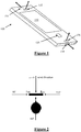
- Figure 1 illustrates a handheld device 100 with touchscreen 110, button 120 and microphones 132, 134, 136, 138.
- the following embodiments describe the capture of audio using such a device, for example to accompany a video recorded by a camera (not shown) of the device.
- Microphone 132 captures a first (primary) left signal L 2
- microphone 134 captures a second (secondary) left signal Li
- microphone 136 captures a first (primary) right signal Ri
- microphone 138 captures a second (secondary) right signal R 2 .
- microphones 132 and 136 are both mounted in ports on a front face of the device 100.
- the port configuration gives microphones 132 and 136 a nominal direction of sensitivity indicated by the respective arrow, each being at a normal to a plane of the front face of the device.
- microphones 134 and 138 are mounted in ports on opposed end surfaces of the device 100.
- the nominal direction of sensitivity of microphone 134 is anti-parallel to that of microphone 138, and perpendicular to that of microphones 132 and 136.
- the following embodiments describe the capture of audio using such a device, for example to accompany a video recorded by a camera (not shown) of the device.
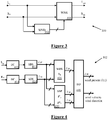
- FIG. 3 A block diagram of a wind noise reduction system 300 in accordance with one embodiment of the present invention is shown in Figure 3 . It is common to combine the digitised (quantised and discretised) samples from L mic (132) and R mic (136) into frames of certain duration (number of elements, M). The input frames are input to the Wind Noise Detector (WND) 302. The WND 302 analyses the frames from the left and right microphones 132, 136 and makes a decision whether, and in which pre-determined sub-band(s), the wind is present during this frame interval.
- WND Wind Noise Detector
- the "per-sub-band" wind presence decisions along with other detection parameters are supplied to the wind noise reduction (WNR) module 304 which applies a chosen technique to reduce wind noise in affected sub-bands while attempting to preserve the target signal (e.g. speech). Any suitable wind noise reduction technique may be applied.
- the WNR outputs L out and R out are output to the end user or for further processing.
- Figure 4 shows a block diagram of the proposed wind noise detector 302.
- the DC modules 402, 404 calculate and remove the DC component from the left and right input channels and supply the DC-free frames to the sub-band splitting (SBS) modules 412, 414.
- the SBS modules 412, 414 (one for each input channel) are used to split full-band frames from each (left and right) channel into N sub-bands.
- Each SBS module 412, 414 consists of N digital filters, each of which only passes on a designated frequency band, and stops (severely attenuates) the rest of the spectral content of the input signal.
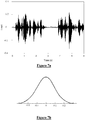
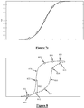
- Figure 7a illustrates a typical speech signal, unaffected by wind noise.
- the distribution of signal sample magnitudes in the signal of Figure 7a is a normal distribution about zero.
- Figure 7c illustrates the cumulative distribution of signal sample magnitudes in the signal of Figure 7a .
- Figure 8 illustrates how the first and second signal cumulative distributions 820, 830 might appear when affected by wind noise. It is noted that the distributions 820, 830 in Figure 8 are shown as dotted lines, because only selected points on each distribution need to be determined in order to put the present embodiment of the invention into effect, and the precise curve need not be determined over its full length at other values.
- each distribution 820, 830 five selected values of each distribution 820, 830 are determined, namely the respective cumulative distribution values at points 821-825 on curve 820, and the respective cumulative distribution values at points 831-835 on curve 830. Then, the absolute value of the differences between the distributions at those values are determined, with one of these five difference values, between the value at 822 and the value at 832, being indicated at 802. As occurs between points 821 and 822, the curves 820 and 830 may cross one or more times, and this is why the absolute values are taken of the differences. Finally, the absolute values of the differences are summed, in order to produce a scalar metric reflecting wind noise.
- a suitable process for determining the metric portrayed in Figures 7 and 8 is as follows.
- WDS wind detection statistic
- the calculated N wind detections statistics D ⁇ n and sub-band powers P ⁇ n Left and P ⁇ n Right are used to make a decision about wind presence in the n-th sub-band, and to produce estimates of wind velocity and wind direction.
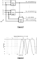
- FIG. 5 shows a block diagram of the DD module 440 in one embodiment of the invention.
- the DD module 440 consists of N Wind Presence Decision (WPD) processor modules 510 ... 512, and a Wind Parameter Estimator (WPE) module 520.
- WPD Wind Presence Decision
- WPE Wind Parameter Estimator
- each n-th, n 1: N of wind presence decision processor, WPD n , 510-512, is input with the corresponding wind detection statistic D ⁇ n determined by wind detection statistic (WDS) calculator module 420, and sub-band powers P ⁇ n Left and P ⁇ n Right determined by the Sub-Band Power (SBP) calculator module 430.
- WPDs 510-512 A binary decision on whether wind is present in the n-th sub-band is made by WPDs 510-512 as follows.
- W n ⁇ 1 , D ⁇ n > DTH R n , P ⁇ n Left and P ⁇ n Right > PTTH R n 0 , otherwise where
- the use of sub-band powers P ⁇ n Left and P ⁇ n Right from the Sub-Band Power (SBP) calculator module 430 may be omitted from the decision device.
- SBP Sub-Band Power
- the decision metric W n + 1 is calculated only if decision W n was positive.
- the WPE 520, 920 performs wind parameter estimation as follows.
- Wind Velocity V w .
- the wind velocity is estimated by determining the variable cut-off frequency f c of the wind spectrum based on the values of W n in each n-th sub-band.
- the cut-off frequency f c is estimated as the right-side pass-band frequency of the highest sub-band B n where wind was detected.
- the frequency resolution of f c estimation is determined by the number N and widths (granularity) of the sub-bands B n .
- the wind noise spectrum is generally a decreasing function of frequency, and its cut-off frequency is a function of wind velocity.
- Device configuration and other factors also affect the wind noise spectrum, and it is to be appreciated in other embodiments that an alternative relationship between wind velocity and wind spectrum cut-off frequency for a different device or configuration can be equivalently determined.
- a wind noise detection threshold set at level 1010 may thus be empirically used to determine that if the variable cut-off frequency f c of the wind spectrum is around 500 Hz as indicated at 1012 then the wind speed is about 2 m/s.
- variable cut-off frequencies f c of the wind spectrum of 2 kHz, 4 kHz and 6 kHz as indicated at 1014, 1016, 1018 can be taken to indicate that the wind speed is 4 m/s, 6 m/s and 8 m/s, respectively.
- Figure 11 is a block diagram of another embodiment of the invention, which provides a single-microphone implementation of the present invention.
- most of the processing is the same as the processing in the dual-microphone wind noise detector 302, as indicated by repeated reference numerals 402, 404, 412, 414, 420, 430, 440.
- both the first input signal I 1 input to the DC removal block 402 and the second input signal I 2 input to the DC removal block 404 are derived from a single microphone input signal X in .
- the first input signal I 1 comprises the audio frame from the microphone received at the current, i -th, time interval.
- the second input signal I 2 is the frame from the same microphone received at the previous frame interval, i - 1 , due to the operation of the single frame delay 1102.
- the module 1102 is used to produce the second signal frame I 2 by applying a single-frame delay to the input signal X in .
- the wind direction of arrival DOA is not estimated in system 1100 due to the absence of spatial diversity in the input signals.
- FIG 12 shows a dual-microphone wind detector 1200 in accordance with yet another embodiment of the invention, in which both spatial and temporal wind detection metrics are determined and utilised.
- the WND 1200 comprises two single-microphone detection metric calculators, SMMC L 1210 and SMMC R 1270, which are input with the left and right microphone signals respectively.
- the WND 1200 further comprises a dual-microphone detection metric calculator, DMMC 1240, which is input with both left and right microphone signals.
- the WND 1200 further comprises a decision combining device, DCD 1290.
- the single-microphone metric calculator for the left microphone, SMMCL 1210 is input with framed audio samples Lin from the left microphone.
- the single-microphone metric calculator for the right microphone SMMC R 1270 is input with framed audio samples from the right microphone.
- the dual-microphone metric calculator 1240 is input with (framed) samples from the left and right microphones.
- the metric calculator estimates wind detection statistics D n and sub-band powers, P n Left and P n Right of the left and right channels, one for each of N sub-bands, based on the audio frames from both left and right microphones, in the same manner as described for WND 302 in relation to Figures 4-10 .
- wind decision statistics DL n , D n , and DR n output by 1210, 1240, 1270, respectively, are smoothed in time to produce smoothed wind decision statistics DL ⁇ n , D ⁇ n , and DR ⁇ n .
- the N sub-band powers, P n Left and P n Right output by 1240 are smoothed in time to produce smoothed sub-band powers P ⁇ n Left and P ⁇ n Right .
- the decision combining device, DCD 1290 receives the smoothed statistics DL ⁇ n , DR ⁇ n , and D ⁇ n and sub-band powers P ⁇ n Left and P ⁇ n Right , and makes a decision as to whether wind is present in each of the n-th sub-bands.
- the wind presence decision metric is produced by combining temporal, DL ⁇ n , DR ⁇ n , and spatial, D ⁇ n , wind statistics into an aggregate statistic, DA ⁇ n .
- DCD 1290 further produces estimates of wind velocity and direction, in the manner described in relation to WPE 520 & 920.
Landscapes
- Engineering & Computer Science (AREA)
- Signal Processing (AREA)
- Physics & Mathematics (AREA)
- Acoustics & Sound (AREA)
- Health & Medical Sciences (AREA)
- Otolaryngology (AREA)
- General Health & Medical Sciences (AREA)
- Neurosurgery (AREA)
- Computational Linguistics (AREA)
- Quality & Reliability (AREA)
- Audiology, Speech & Language Pathology (AREA)
- Human Computer Interaction (AREA)
- Multimedia (AREA)
- Circuit For Audible Band Transducer (AREA)
Applications Claiming Priority (3)
| Application Number | Priority Date | Filing Date | Title |
|---|---|---|---|
| AU2014902804A AU2014902804A0 (en) | 2014-07-21 | Method and Apparatus for Wind Noise Detection | |
| AU2015900265A AU2015900265A0 (en) | 2015-01-29 | Method and Apparatus for Wind Noise Detection | |
| PCT/AU2015/050406 WO2016011499A1 (en) | 2014-07-21 | 2015-07-21 | Method and apparatus for wind noise detection |
Publications (3)
| Publication Number | Publication Date |
|---|---|
| EP3172906A1 EP3172906A1 (en) | 2017-05-31 |
| EP3172906A4 EP3172906A4 (en) | 2018-01-10 |
| EP3172906B1 true EP3172906B1 (en) | 2019-04-03 |
Family
ID=55162321
Family Applications (1)
| Application Number | Title | Priority Date | Filing Date |
|---|---|---|---|
| EP15824154.7A Active EP3172906B1 (en) | 2014-07-21 | 2015-07-21 | Method and apparatus for wind noise detection |
Country Status (6)
| Country | Link |
|---|---|
| US (2) | US9906882B2 (zh) |
| EP (1) | EP3172906B1 (zh) |
| KR (1) | KR102313894B1 (zh) |
| CN (1) | CN106664486B (zh) |
| AU (1) | AU2015292259A1 (zh) |
| WO (1) | WO2016011499A1 (zh) |
Families Citing this family (20)
| Publication number | Priority date | Publication date | Assignee | Title |
|---|---|---|---|---|
| JP6697778B2 (ja) * | 2015-05-12 | 2020-05-27 | 日本電気株式会社 | 信号処理装置、信号処理方法および信号処理プログラム |
| US11017793B2 (en) * | 2015-12-18 | 2021-05-25 | Dolby Laboratories Licensing Corporation | Nuisance notification |
| GB2555139A (en) | 2016-10-21 | 2018-04-25 | Nokia Technologies Oy | Detecting the presence of wind noise |
| KR20180108155A (ko) * | 2017-03-24 | 2018-10-04 | 삼성전자주식회사 | 바람 소리가 조정된 신호를 출력하는 방법 및 전자 장치 |
| US10366710B2 (en) | 2017-06-09 | 2019-07-30 | Nxp B.V. | Acoustic meaningful signal detection in wind noise |
| US10504537B2 (en) | 2018-02-02 | 2019-12-10 | Cirrus Logic, Inc. | Wind noise measurement |
| TWI690218B (zh) * | 2018-06-15 | 2020-04-01 | 瑞昱半導體股份有限公司 | 耳機 |
| US11100918B2 (en) * | 2018-08-27 | 2021-08-24 | American Family Mutual Insurance Company, S.I. | Event sensing system |
| CN109286875B (zh) * | 2018-09-29 | 2021-01-01 | 百度在线网络技术(北京)有限公司 | 用于定向拾音的方法、装置、电子设备和存储介质 |
| CN109257675B (zh) * | 2018-10-19 | 2019-12-10 | 歌尔科技有限公司 | 一种防风噪方法、耳机及存储介质 |
| GB201902812D0 (en) * | 2019-03-01 | 2019-04-17 | Nokia Technologies Oy | Wind noise reduction in parametric audio |
| US10721562B1 (en) * | 2019-04-30 | 2020-07-21 | Synaptics Incorporated | Wind noise detection systems and methods |
| US10917716B2 (en) * | 2019-06-19 | 2021-02-09 | Cirrus Logic, Inc. | Apparatus for and method of wind detection |
| US11290809B2 (en) | 2019-07-14 | 2022-03-29 | Peiker Acustic Gmbh | Dynamic sensitivity matching of microphones in a microphone array |
| TWI779261B (zh) * | 2020-01-22 | 2022-10-01 | 仁寶電腦工業股份有限公司 | 風切濾波裝置 |
| US11217269B2 (en) | 2020-01-24 | 2022-01-04 | Continental Automotive Systems, Inc. | Method and apparatus for wind noise attenuation |
| US11308972B1 (en) * | 2020-05-11 | 2022-04-19 | Facebook Technologies, Llc | Systems and methods for reducing wind noise |
| CN112653979A (zh) * | 2020-12-29 | 2021-04-13 | 苏州思必驰信息科技有限公司 | 自适应去混响方法和装置 |
| US11812243B2 (en) | 2021-03-18 | 2023-11-07 | Bang & Olufsen A/S | Headset capable of compensating for wind noise |
| CN113670369B (zh) * | 2021-07-09 | 2023-01-06 | 南京航空航天大学 | 基于移动终端的风速测量及风噪声检测方法及装置 |
Family Cites Families (12)
| Publication number | Priority date | Publication date | Assignee | Title |
|---|---|---|---|---|
| DE10045197C1 (de) | 2000-09-13 | 2002-03-07 | Siemens Audiologische Technik | Verfahren zum Betrieb eines Hörhilfegerätes oder Hörgerätessystems sowie Hörhilfegerät oder Hörgerätesystem |
| US7171008B2 (en) | 2002-02-05 | 2007-01-30 | Mh Acoustics, Llc | Reducing noise in audio systems |
| US7340068B2 (en) | 2003-02-19 | 2008-03-04 | Oticon A/S | Device and method for detecting wind noise |
| US7464029B2 (en) * | 2005-07-22 | 2008-12-09 | Qualcomm Incorporated | Robust separation of speech signals in a noisy environment |
| US8184816B2 (en) * | 2008-03-18 | 2012-05-22 | Qualcomm Incorporated | Systems and methods for detecting wind noise using multiple audio sources |
| JP2011030022A (ja) * | 2009-07-27 | 2011-02-10 | Canon Inc | 雑音判定装置、音声記録装置、及び雑音判定装置の制御方法 |
| US9330675B2 (en) * | 2010-11-12 | 2016-05-03 | Broadcom Corporation | Method and apparatus for wind noise detection and suppression using multiple microphones |
| EP2673956B1 (en) * | 2011-02-10 | 2019-04-24 | Dolby Laboratories Licensing Corporation | System and method for wind detection and suppression |
| EP2780906B1 (en) * | 2011-12-22 | 2016-09-14 | Cirrus Logic International Semiconductor Limited | Method and apparatus for wind noise detection |
| US9549250B2 (en) * | 2012-06-10 | 2017-01-17 | Nuance Communications, Inc. | Wind noise detection for in-car communication systems with multiple acoustic zones |
| EP2848007B1 (en) * | 2012-10-15 | 2021-03-17 | MH Acoustics, LLC | Noise-reducing directional microphone array |
| WO2014104815A1 (ko) * | 2012-12-28 | 2014-07-03 | 한국과학기술연구원 | 바람 소음 제거를 통한 음원 위치 추적 장치 및 그 방법 |
-
2015
- 2015-07-21 WO PCT/AU2015/050406 patent/WO2016011499A1/en active Application Filing
- 2015-07-21 AU AU2015292259A patent/AU2015292259A1/en not_active Abandoned
- 2015-07-21 CN CN201580039259.XA patent/CN106664486B/zh active Active
- 2015-07-21 US US15/324,091 patent/US9906882B2/en active Active
- 2015-07-21 EP EP15824154.7A patent/EP3172906B1/en active Active
- 2015-07-21 KR KR1020177004541A patent/KR102313894B1/ko active IP Right Grant
-
2017
- 2017-12-27 US US15/855,556 patent/US10251005B2/en active Active
Non-Patent Citations (1)
| Title |
|---|
| None * |
Also Published As
| Publication number | Publication date |
|---|---|
| AU2015292259A1 (en) | 2016-12-15 |
| US20170208407A1 (en) | 2017-07-20 |
| EP3172906A4 (en) | 2018-01-10 |
| KR102313894B1 (ko) | 2021-10-18 |
| CN106664486A (zh) | 2017-05-10 |
| US20180176704A1 (en) | 2018-06-21 |
| KR20170034405A (ko) | 2017-03-28 |
| WO2016011499A1 (en) | 2016-01-28 |
| CN106664486B (zh) | 2019-06-28 |
| US10251005B2 (en) | 2019-04-02 |
| US9906882B2 (en) | 2018-02-27 |
| EP3172906A1 (en) | 2017-05-31 |
Similar Documents
| Publication | Publication Date | Title |
|---|---|---|
| EP3172906B1 (en) | Method and apparatus for wind noise detection | |
| US10602267B2 (en) | Sound signal processing apparatus and method for enhancing a sound signal | |
| KR101597752B1 (ko) | 잡음 추정 장치 및 방법과, 이를 이용한 잡음 감소 장치 | |
| EP2751806B1 (en) | A method and a system for noise suppressing an audio signal | |
| US7464029B2 (en) | Robust separation of speech signals in a noisy environment | |
| EP2297727B1 (en) | Multi-microphone voice activity detector | |
| WO2015196760A1 (zh) | 一种麦克风阵列语音检测方法及装置 | |
| CN106875938B (zh) | 一种改进的非线性自适应语音端点检测方法 | |
| TWI720314B (zh) | 基於相關性之近場偵測器 | |
| JP2009522942A (ja) | 発話改善のためにマイク間レベル差を用いるシステム及び方法 | |
| JP4816711B2 (ja) | 通話音声処理装置および通話音声処理方法 | |
| JP2010112996A (ja) | 音声処理装置、音声処理方法およびプログラム | |
| US10504537B2 (en) | Wind noise measurement | |
| KR20090037845A (ko) | 혼합 신호로부터 목표 음원 신호를 추출하는 방법 및 장치 | |
| CN110169082B (zh) | 用于组合音频信号输出的方法和装置、及计算机可读介质 | |
| CN108389590B (zh) | 一种时频联合的语音削顶检测方法 | |
| CN110708651A (zh) | 一种基于分段陷波的助听器啸叫检测与抑制方法及装置 | |
| Sapozhnykov | Sub-band detector for wind-induced noise | |
| KR101096091B1 (ko) | 음성 분리 장치 및 이를 이용한 단일 채널 음성 분리 방법 | |
| JP6361360B2 (ja) | 残響判定装置及びプログラム | |
| Moghimi et al. | An analysis of binaural spectro-temporal masking as nonlinear beamforming | |
| Kako et al. | Wiener filter design by estimating sensitivities between distributed asynchronous microphones and sound sources | |
| KR101817421B1 (ko) | 두 채널 구조에 기초하는 사전 음성 부재 확률의 추정 방법 | |
| Shanmugapriya et al. | A thorough investigation on speech enhancement techniques for hearing aids | |
| Zhang et al. | Speech enhancement using improved adaptive null-forming in frequency domain with postfilter |
Legal Events
| Date | Code | Title | Description |
|---|---|---|---|
| STAA | Information on the status of an ep patent application or granted ep patent |
Free format text: STATUS: THE INTERNATIONAL PUBLICATION HAS BEEN MADE |
|
| PUAI | Public reference made under article 153(3) epc to a published international application that has entered the european phase |
Free format text: ORIGINAL CODE: 0009012 |
|
| STAA | Information on the status of an ep patent application or granted ep patent |
Free format text: STATUS: REQUEST FOR EXAMINATION WAS MADE |
|
| 17P | Request for examination filed |
Effective date: 20161213 |
|
| AK | Designated contracting states |
Kind code of ref document: A1 Designated state(s): AL AT BE BG CH CY CZ DE DK EE ES FI FR GB GR HR HU IE IS IT LI LT LU LV MC MK MT NL NO PL PT RO RS SE SI SK SM TR |
|
| AX | Request for extension of the european patent |
Extension state: BA ME |
|
| DAV | Request for validation of the european patent (deleted) | ||
| DAX | Request for extension of the european patent (deleted) | ||
| A4 | Supplementary search report drawn up and despatched |
Effective date: 20171212 |
|
| RIC1 | Information provided on ipc code assigned before grant |
Ipc: G10L 21/0208 20130101ALI20171206BHEP Ipc: H04R 3/02 20060101AFI20171206BHEP Ipc: H04R 25/00 20060101ALI20171206BHEP |
|
| GRAP | Despatch of communication of intention to grant a patent |
Free format text: ORIGINAL CODE: EPIDOSNIGR1 |
|
| STAA | Information on the status of an ep patent application or granted ep patent |
Free format text: STATUS: GRANT OF PATENT IS INTENDED |
|
| INTG | Intention to grant announced |
Effective date: 20190104 |
|
| GRAS | Grant fee paid |
Free format text: ORIGINAL CODE: EPIDOSNIGR3 |
|
| GRAA | (expected) grant |
Free format text: ORIGINAL CODE: 0009210 |
|
| STAA | Information on the status of an ep patent application or granted ep patent |
Free format text: STATUS: THE PATENT HAS BEEN GRANTED |
|
| AK | Designated contracting states |
Kind code of ref document: B1 Designated state(s): AL AT BE BG CH CY CZ DE DK EE ES FI FR GB GR HR HU IE IS IT LI LT LU LV MC MK MT NL NO PL PT RO RS SE SI SK SM TR |
|
| REG | Reference to a national code |
Ref country code: GB Ref legal event code: FG4D |
|
| REG | Reference to a national code |
Ref country code: CH Ref legal event code: EP Ref country code: AT Ref legal event code: REF Ref document number: 1117261 Country of ref document: AT Kind code of ref document: T Effective date: 20190415 |
|
| REG | Reference to a national code |
Ref country code: DE Ref legal event code: R096 Ref document number: 602015027763 Country of ref document: DE |
|
| REG | Reference to a national code |
Ref country code: IE Ref legal event code: FG4D |
|
| REG | Reference to a national code |
Ref country code: NL Ref legal event code: MP Effective date: 20190403 |
|
| REG | Reference to a national code |
Ref country code: LT Ref legal event code: MG4D |
|
| REG | Reference to a national code |
Ref country code: AT Ref legal event code: MK05 Ref document number: 1117261 Country of ref document: AT Kind code of ref document: T Effective date: 20190403 |
|
| PG25 | Lapsed in a contracting state [announced via postgrant information from national office to epo] |
Ref country code: NL Free format text: LAPSE BECAUSE OF FAILURE TO SUBMIT A TRANSLATION OF THE DESCRIPTION OR TO PAY THE FEE WITHIN THE PRESCRIBED TIME-LIMIT Effective date: 20190403 |
|
| PG25 | Lapsed in a contracting state [announced via postgrant information from national office to epo] |
Ref country code: CZ Free format text: LAPSE BECAUSE OF FAILURE TO SUBMIT A TRANSLATION OF THE DESCRIPTION OR TO PAY THE FEE WITHIN THE PRESCRIBED TIME-LIMIT Effective date: 20190403 Ref country code: ES Free format text: LAPSE BECAUSE OF FAILURE TO SUBMIT A TRANSLATION OF THE DESCRIPTION OR TO PAY THE FEE WITHIN THE PRESCRIBED TIME-LIMIT Effective date: 20190403 Ref country code: LT Free format text: LAPSE BECAUSE OF FAILURE TO SUBMIT A TRANSLATION OF THE DESCRIPTION OR TO PAY THE FEE WITHIN THE PRESCRIBED TIME-LIMIT Effective date: 20190403 Ref country code: HR Free format text: LAPSE BECAUSE OF FAILURE TO SUBMIT A TRANSLATION OF THE DESCRIPTION OR TO PAY THE FEE WITHIN THE PRESCRIBED TIME-LIMIT Effective date: 20190403 Ref country code: FI Free format text: LAPSE BECAUSE OF FAILURE TO SUBMIT A TRANSLATION OF THE DESCRIPTION OR TO PAY THE FEE WITHIN THE PRESCRIBED TIME-LIMIT Effective date: 20190403 Ref country code: AL Free format text: LAPSE BECAUSE OF FAILURE TO SUBMIT A TRANSLATION OF THE DESCRIPTION OR TO PAY THE FEE WITHIN THE PRESCRIBED TIME-LIMIT Effective date: 20190403 Ref country code: PT Free format text: LAPSE BECAUSE OF FAILURE TO SUBMIT A TRANSLATION OF THE DESCRIPTION OR TO PAY THE FEE WITHIN THE PRESCRIBED TIME-LIMIT Effective date: 20190803 Ref country code: SE Free format text: LAPSE BECAUSE OF FAILURE TO SUBMIT A TRANSLATION OF THE DESCRIPTION OR TO PAY THE FEE WITHIN THE PRESCRIBED TIME-LIMIT Effective date: 20190403 Ref country code: NO Free format text: LAPSE BECAUSE OF FAILURE TO SUBMIT A TRANSLATION OF THE DESCRIPTION OR TO PAY THE FEE WITHIN THE PRESCRIBED TIME-LIMIT Effective date: 20190703 |
|
| PG25 | Lapsed in a contracting state [announced via postgrant information from national office to epo] |
Ref country code: LV Free format text: LAPSE BECAUSE OF FAILURE TO SUBMIT A TRANSLATION OF THE DESCRIPTION OR TO PAY THE FEE WITHIN THE PRESCRIBED TIME-LIMIT Effective date: 20190403 Ref country code: PL Free format text: LAPSE BECAUSE OF FAILURE TO SUBMIT A TRANSLATION OF THE DESCRIPTION OR TO PAY THE FEE WITHIN THE PRESCRIBED TIME-LIMIT Effective date: 20190403 Ref country code: GR Free format text: LAPSE BECAUSE OF FAILURE TO SUBMIT A TRANSLATION OF THE DESCRIPTION OR TO PAY THE FEE WITHIN THE PRESCRIBED TIME-LIMIT Effective date: 20190704 Ref country code: RS Free format text: LAPSE BECAUSE OF FAILURE TO SUBMIT A TRANSLATION OF THE DESCRIPTION OR TO PAY THE FEE WITHIN THE PRESCRIBED TIME-LIMIT Effective date: 20190403 Ref country code: BG Free format text: LAPSE BECAUSE OF FAILURE TO SUBMIT A TRANSLATION OF THE DESCRIPTION OR TO PAY THE FEE WITHIN THE PRESCRIBED TIME-LIMIT Effective date: 20190703 |
|
| PG25 | Lapsed in a contracting state [announced via postgrant information from national office to epo] |
Ref country code: AT Free format text: LAPSE BECAUSE OF FAILURE TO SUBMIT A TRANSLATION OF THE DESCRIPTION OR TO PAY THE FEE WITHIN THE PRESCRIBED TIME-LIMIT Effective date: 20190403 Ref country code: IS Free format text: LAPSE BECAUSE OF FAILURE TO SUBMIT A TRANSLATION OF THE DESCRIPTION OR TO PAY THE FEE WITHIN THE PRESCRIBED TIME-LIMIT Effective date: 20190803 |
|
| REG | Reference to a national code |
Ref country code: DE Ref legal event code: R097 Ref document number: 602015027763 Country of ref document: DE |
|
| PG25 | Lapsed in a contracting state [announced via postgrant information from national office to epo] |
Ref country code: RO Free format text: LAPSE BECAUSE OF FAILURE TO SUBMIT A TRANSLATION OF THE DESCRIPTION OR TO PAY THE FEE WITHIN THE PRESCRIBED TIME-LIMIT Effective date: 20190403 Ref country code: EE Free format text: LAPSE BECAUSE OF FAILURE TO SUBMIT A TRANSLATION OF THE DESCRIPTION OR TO PAY THE FEE WITHIN THE PRESCRIBED TIME-LIMIT Effective date: 20190403 Ref country code: DK Free format text: LAPSE BECAUSE OF FAILURE TO SUBMIT A TRANSLATION OF THE DESCRIPTION OR TO PAY THE FEE WITHIN THE PRESCRIBED TIME-LIMIT Effective date: 20190403 Ref country code: SK Free format text: LAPSE BECAUSE OF FAILURE TO SUBMIT A TRANSLATION OF THE DESCRIPTION OR TO PAY THE FEE WITHIN THE PRESCRIBED TIME-LIMIT Effective date: 20190403 |
|
| PLBE | No opposition filed within time limit |
Free format text: ORIGINAL CODE: 0009261 |
|
| STAA | Information on the status of an ep patent application or granted ep patent |
Free format text: STATUS: NO OPPOSITION FILED WITHIN TIME LIMIT |
|
| PG25 | Lapsed in a contracting state [announced via postgrant information from national office to epo] |
Ref country code: IT Free format text: LAPSE BECAUSE OF FAILURE TO SUBMIT A TRANSLATION OF THE DESCRIPTION OR TO PAY THE FEE WITHIN THE PRESCRIBED TIME-LIMIT Effective date: 20190403 Ref country code: SM Free format text: LAPSE BECAUSE OF FAILURE TO SUBMIT A TRANSLATION OF THE DESCRIPTION OR TO PAY THE FEE WITHIN THE PRESCRIBED TIME-LIMIT Effective date: 20190403 Ref country code: MC Free format text: LAPSE BECAUSE OF FAILURE TO SUBMIT A TRANSLATION OF THE DESCRIPTION OR TO PAY THE FEE WITHIN THE PRESCRIBED TIME-LIMIT Effective date: 20190403 |
|
| REG | Reference to a national code |
Ref country code: CH Ref legal event code: PL |
|
| 26N | No opposition filed |
Effective date: 20200106 |
|
| PG25 | Lapsed in a contracting state [announced via postgrant information from national office to epo] |
Ref country code: TR Free format text: LAPSE BECAUSE OF FAILURE TO SUBMIT A TRANSLATION OF THE DESCRIPTION OR TO PAY THE FEE WITHIN THE PRESCRIBED TIME-LIMIT Effective date: 20190403 |
|
| REG | Reference to a national code |
Ref country code: BE Ref legal event code: MM Effective date: 20190731 |
|
| PG25 | Lapsed in a contracting state [announced via postgrant information from national office to epo] |
Ref country code: SI Free format text: LAPSE BECAUSE OF FAILURE TO SUBMIT A TRANSLATION OF THE DESCRIPTION OR TO PAY THE FEE WITHIN THE PRESCRIBED TIME-LIMIT Effective date: 20190403 Ref country code: BE Free format text: LAPSE BECAUSE OF NON-PAYMENT OF DUE FEES Effective date: 20190731 Ref country code: LU Free format text: LAPSE BECAUSE OF NON-PAYMENT OF DUE FEES Effective date: 20190721 Ref country code: CH Free format text: LAPSE BECAUSE OF NON-PAYMENT OF DUE FEES Effective date: 20190731 Ref country code: LI Free format text: LAPSE BECAUSE OF NON-PAYMENT OF DUE FEES Effective date: 20190731 |
|
| PG25 | Lapsed in a contracting state [announced via postgrant information from national office to epo] |
Ref country code: IE Free format text: LAPSE BECAUSE OF NON-PAYMENT OF DUE FEES Effective date: 20190721 |
|
| REG | Reference to a national code |
Ref country code: DE Ref legal event code: R082 Ref document number: 602015027763 Country of ref document: DE Representative=s name: HL KEMPNER PATENTANWAELTE, SOLICITORS (ENGLAND, DE Ref country code: DE Ref legal event code: R082 Ref document number: 602015027763 Country of ref document: DE Representative=s name: HL KEMPNER PATENTANWALT, RECHTSANWALT, SOLICIT, DE |
|
| PG25 | Lapsed in a contracting state [announced via postgrant information from national office to epo] |
Ref country code: CY Free format text: LAPSE BECAUSE OF FAILURE TO SUBMIT A TRANSLATION OF THE DESCRIPTION OR TO PAY THE FEE WITHIN THE PRESCRIBED TIME-LIMIT Effective date: 20190403 |
|
| PG25 | Lapsed in a contracting state [announced via postgrant information from national office to epo] |
Ref country code: HU Free format text: LAPSE BECAUSE OF FAILURE TO SUBMIT A TRANSLATION OF THE DESCRIPTION OR TO PAY THE FEE WITHIN THE PRESCRIBED TIME-LIMIT; INVALID AB INITIO Effective date: 20150721 Ref country code: MT Free format text: LAPSE BECAUSE OF FAILURE TO SUBMIT A TRANSLATION OF THE DESCRIPTION OR TO PAY THE FEE WITHIN THE PRESCRIBED TIME-LIMIT Effective date: 20190403 |
|
| PG25 | Lapsed in a contracting state [announced via postgrant information from national office to epo] |
Ref country code: MK Free format text: LAPSE BECAUSE OF FAILURE TO SUBMIT A TRANSLATION OF THE DESCRIPTION OR TO PAY THE FEE WITHIN THE PRESCRIBED TIME-LIMIT Effective date: 20190403 |
|
| PGFP | Annual fee paid to national office [announced via postgrant information from national office to epo] |
Ref country code: DE Payment date: 20220727 Year of fee payment: 8 |
|
| PGFP | Annual fee paid to national office [announced via postgrant information from national office to epo] |
Ref country code: FR Payment date: 20220725 Year of fee payment: 8 |
|
| P01 | Opt-out of the competence of the unified patent court (upc) registered |
Effective date: 20230322 |
|
| PGFP | Annual fee paid to national office [announced via postgrant information from national office to epo] |
Ref country code: GB Payment date: 20230727 Year of fee payment: 9 |
|
| REG | Reference to a national code |
Ref country code: DE Ref legal event code: R119 Ref document number: 602015027763 Country of ref document: DE |
|
| PG25 | Lapsed in a contracting state [announced via postgrant information from national office to epo] |
Ref country code: DE Free format text: LAPSE BECAUSE OF NON-PAYMENT OF DUE FEES Effective date: 20240201 |