EP3172502B1 - Systems and methods for operating a thermoelectric module to increase efficiency - Google Patents
Systems and methods for operating a thermoelectric module to increase efficiency Download PDFInfo
- Publication number
- EP3172502B1 EP3172502B1 EP15745336.6A EP15745336A EP3172502B1 EP 3172502 B1 EP3172502 B1 EP 3172502B1 EP 15745336 A EP15745336 A EP 15745336A EP 3172502 B1 EP3172502 B1 EP 3172502B1
- Authority
- EP
- European Patent Office
- Prior art keywords
- amount
- power
- thermoelectric module
- tem
- temperature
- Prior art date
- Legal status (The legal status is an assumption and is not a legal conclusion. Google has not performed a legal analysis and makes no representation as to the accuracy of the status listed.)
- Active
Links
- 238000000034 method Methods 0.000 title claims description 53
- 238000001816 cooling Methods 0.000 claims description 69
- 238000005057 refrigeration Methods 0.000 claims description 39
- 238000004590 computer program Methods 0.000 claims description 4
- 230000003287 optical effect Effects 0.000 claims description 2
- 238000013169 thromboelastometry Methods 0.000 description 15
- 238000004627 transmission electron microscopy Methods 0.000 description 15
- 230000007423 decrease Effects 0.000 description 14
- 230000006835 compression Effects 0.000 description 8
- 238000007906 compression Methods 0.000 description 8
- 230000001276 controlling effect Effects 0.000 description 6
- 238000013021 overheating Methods 0.000 description 6
- 229920006395 saturated elastomer Polymers 0.000 description 5
- 239000002826 coolant Substances 0.000 description 4
- 238000010586 diagram Methods 0.000 description 4
- 230000008859 change Effects 0.000 description 3
- 238000000605 extraction Methods 0.000 description 2
- 230000017525 heat dissipation Effects 0.000 description 2
- 239000000463 material Substances 0.000 description 2
- 230000000116 mitigating effect Effects 0.000 description 2
- 238000012986 modification Methods 0.000 description 2
- 230000004048 modification Effects 0.000 description 2
- 230000010355 oscillation Effects 0.000 description 2
- 238000012360 testing method Methods 0.000 description 2
- RYGMFSIKBFXOCR-UHFFFAOYSA-N Copper Chemical compound [Cu] RYGMFSIKBFXOCR-UHFFFAOYSA-N 0.000 description 1
- 238000009825 accumulation Methods 0.000 description 1
- 230000009471 action Effects 0.000 description 1
- XAGFODPZIPBFFR-UHFFFAOYSA-N aluminium Chemical compound [Al] XAGFODPZIPBFFR-UHFFFAOYSA-N 0.000 description 1
- 229910052782 aluminium Inorganic materials 0.000 description 1
- 230000009286 beneficial effect Effects 0.000 description 1
- 229910052802 copper Inorganic materials 0.000 description 1
- 239000010949 copper Substances 0.000 description 1
- 230000008878 coupling Effects 0.000 description 1
- 238000010168 coupling process Methods 0.000 description 1
- 238000005859 coupling reaction Methods 0.000 description 1
- 230000001351 cycling effect Effects 0.000 description 1
- 230000003247 decreasing effect Effects 0.000 description 1
- 230000001419 dependent effect Effects 0.000 description 1
- 230000000694 effects Effects 0.000 description 1
- 238000005265 energy consumption Methods 0.000 description 1
- 239000000284 extract Substances 0.000 description 1
- 238000009413 insulation Methods 0.000 description 1
- 230000007246 mechanism Effects 0.000 description 1
- 238000009428 plumbing Methods 0.000 description 1
- 230000002028 premature Effects 0.000 description 1
- 230000008569 process Effects 0.000 description 1
- 238000005086 pumping Methods 0.000 description 1
- 238000011084 recovery Methods 0.000 description 1
- 230000001105 regulatory effect Effects 0.000 description 1
- 230000004044 response Effects 0.000 description 1
- 230000000630 rising effect Effects 0.000 description 1
- 239000004065 semiconductor Substances 0.000 description 1
- 229910001220 stainless steel Inorganic materials 0.000 description 1
- 239000010935 stainless steel Substances 0.000 description 1
- 238000013517 stratification Methods 0.000 description 1
- 239000010409 thin film Substances 0.000 description 1
- 238000012546 transfer Methods 0.000 description 1
- 230000001052 transient effect Effects 0.000 description 1
Images


Classifications
-
- F—MECHANICAL ENGINEERING; LIGHTING; HEATING; WEAPONS; BLASTING
- F25—REFRIGERATION OR COOLING; COMBINED HEATING AND REFRIGERATION SYSTEMS; HEAT PUMP SYSTEMS; MANUFACTURE OR STORAGE OF ICE; LIQUEFACTION SOLIDIFICATION OF GASES
- F25B—REFRIGERATION MACHINES, PLANTS OR SYSTEMS; COMBINED HEATING AND REFRIGERATION SYSTEMS; HEAT PUMP SYSTEMS
- F25B21/00—Machines, plants or systems, using electric or magnetic effects
- F25B21/02—Machines, plants or systems, using electric or magnetic effects using Peltier effect; using Nernst-Ettinghausen effect
-
- F—MECHANICAL ENGINEERING; LIGHTING; HEATING; WEAPONS; BLASTING
- F25—REFRIGERATION OR COOLING; COMBINED HEATING AND REFRIGERATION SYSTEMS; HEAT PUMP SYSTEMS; MANUFACTURE OR STORAGE OF ICE; LIQUEFACTION SOLIDIFICATION OF GASES
- F25B—REFRIGERATION MACHINES, PLANTS OR SYSTEMS; COMBINED HEATING AND REFRIGERATION SYSTEMS; HEAT PUMP SYSTEMS
- F25B49/00—Arrangement or mounting of control or safety devices
-
- F—MECHANICAL ENGINEERING; LIGHTING; HEATING; WEAPONS; BLASTING
- F25—REFRIGERATION OR COOLING; COMBINED HEATING AND REFRIGERATION SYSTEMS; HEAT PUMP SYSTEMS; MANUFACTURE OR STORAGE OF ICE; LIQUEFACTION SOLIDIFICATION OF GASES
- F25B—REFRIGERATION MACHINES, PLANTS OR SYSTEMS; COMBINED HEATING AND REFRIGERATION SYSTEMS; HEAT PUMP SYSTEMS
- F25B2321/00—Details of machines, plants or systems, using electric or magnetic effects
- F25B2321/02—Details of machines, plants or systems, using electric or magnetic effects using Peltier effects; using Nernst-Ettinghausen effects
- F25B2321/021—Control thereof
- F25B2321/0212—Control thereof of electric power, current or voltage
-
- F—MECHANICAL ENGINEERING; LIGHTING; HEATING; WEAPONS; BLASTING
- F25—REFRIGERATION OR COOLING; COMBINED HEATING AND REFRIGERATION SYSTEMS; HEAT PUMP SYSTEMS; MANUFACTURE OR STORAGE OF ICE; LIQUEFACTION SOLIDIFICATION OF GASES
- F25B—REFRIGERATION MACHINES, PLANTS OR SYSTEMS; COMBINED HEATING AND REFRIGERATION SYSTEMS; HEAT PUMP SYSTEMS
- F25B2700/00—Sensing or detecting of parameters; Sensors therefor
- F25B2700/21—Temperatures
- F25B2700/2104—Temperatures of an indoor room or compartment
-
- F—MECHANICAL ENGINEERING; LIGHTING; HEATING; WEAPONS; BLASTING
- F25—REFRIGERATION OR COOLING; COMBINED HEATING AND REFRIGERATION SYSTEMS; HEAT PUMP SYSTEMS; MANUFACTURE OR STORAGE OF ICE; LIQUEFACTION SOLIDIFICATION OF GASES
- F25B—REFRIGERATION MACHINES, PLANTS OR SYSTEMS; COMBINED HEATING AND REFRIGERATION SYSTEMS; HEAT PUMP SYSTEMS
- F25B2700/00—Sensing or detecting of parameters; Sensors therefor
- F25B2700/21—Temperatures
- F25B2700/2107—Temperatures of a Peltier element
Definitions
- thermoelectric module The present disclosure relates to operation of a thermoelectric module.
- the sub-optimum efficiency disadvantage of vapor compression based refrigeration systems relates to precisely controlling the temperature within a cooling chamber.
- the vapor compression based refrigeration system activates and continues to run until the temperature in the cooling chamber is below the certain value. Once the cooling chamber reaches a temperature below the certain value, the vapor compression based refrigeration system shuts off.
- this type of control scheme will typically have a relatively large control band and a relatively large internal temperature stratification in an effort to minimize energy consumption and allow for operation in varied ambient conditions. This regime is most often utilized because throttling or capacity variation is difficult and expensive to implement into the vapor compression cycle and provides limited efficacy as volumetric efficiency falls.
- US 2009/293500 A1 discloses a method of controlling a thermoelectric system and a control device which adjusts the direct current supplied to the thermoelectric module based on a temperature differential between the hot and cold side of the module and on material properties of the semi-conductor based materials in order to maximize the coefficient of performance of the thermoelectric module.
- a method of operating a thermoelectric module in a thermoelectric refrigeration system is defined by claim 1.
- a method of operating a thermoelectric module includes determining a first amount of power that would maximize a coefficient of performance of the thermoelectric module based on one or more system parameters comprising an ambient temperature of an environment that is external to the cooling chamber, and providing the first amount of power to the thermoelectric module.
- the method also includes determining that at least one of the one or more system parameters has changed, determining a second amount of power that would maximize the coefficient of performance of the thermoelectric module based on the one or more system parameters, and providing the second amount of power to the thermoelectric module.
- adjusting the amount of power provided based on the one or more system parameters increases the efficiency of the thermoelectric module.
- providing the first amount of power to the thermoelectric module includes providing a first amount of current to the thermoelectric module, and providing the second amount of power to the thermoelectric module includes providing a second amount of current to the thermoelectric module. In some embodiments, providing the first amount of power to the thermoelectric module includes providing a first amount of voltage to the thermoelectric module, and providing the second amount of power to the thermoelectric module includes providing a second amount of voltage to the thermoelectric module.
- the thermoelectric module is operative to reduce a temperature of a cooling chamber.
- the first amount of power and/or the second amount of power is determined based on the temperature of the cooling chamber, a temperature of a hot side of the thermoelectric module, and/or an electric property of the thermoelectric module such as the figure of merit.
- determining the first amount of power includes determining the first amount of power that would maximize the coefficient of performance of the thermoelectric module based on the ambient temperature of the environment that is external to the cooling chamber; determining that at least one of the one or more system parameters has changed includes determining that the temperature of the environment that is external to the cooling chamber has changed; and determining the second amount of power includes determining the second amount of power that would maximize the coefficient of performance of the thermoelectric module based on the temperature of the environment that is external to the cooling chamber.
- determining the first amount of power includes determining the first amount of power that would maximize the coefficient of performance of the thermoelectric module based on the one or more system parameters using a lookup table; and determining the second amount of power includes determining the second amount of power that would maximize the coefficient of performance of the thermoelectric module based on the one or more system parameters using the lookup table.
- providing the first amount of power to the thermoelectric module also includes providing the first amount of power to one subset of more than one subset of thermoelectric modules, and providing the second amount of power to the thermoelectric module also includes providing the second amount of power to the one subset of the more than one subset of thermoelectric modules.
- the method also includes determining that a temperature of a hot side of the thermoelectric module is above a first threshold, and providing an amount of power to the thermoelectric module that is less than the amount of power that would maximize the coefficient of performance of the thermoelectric module based on the one or more system parameters.
- the method also includes determining that the temperature of the hot side of the thermoelectric module is below a second threshold, and providing an amount of power to the thermoelectric module that is the amount of power that would maximize the coefficient of performance of the thermoelectric module based on the one or more system parameters.
- thermoelectric refrigeration system includes a cooling chamber, a heat exchanger, and a controller.
- the heat exchanger includes a cold side heat sink, a hot side heat sink, and a thermoelectric module disposed between the cold side heat sink and the hot side heat sink.
- the controller is configured to determine a first amount of power that would maximize a coefficient of performance of the thermoelectric module based on one or more system parameters comprising an ambient temperature of an environment that is external to the cooling chamber; and provide the first amount of power to the thermoelectric module.
- the controller is also configured to determine that at least one of the one or more system parameters has changed; determine a second amount of power that would maximize the coefficient of performance of the thermoelectric module based on the one or more system parameters; and provide the second amount of power to the thermoelectric module.
- the controller for operating a thermoelectric module is adapted to determine a first amount of power that would maximize a coefficient of performance of the thermoelectric module based on one or more system parameters comprising an ambient temperature of an environment that is external to the cooling chamber; provide the first amount of power to the thermoelectric module; determine that at least one of the one or more system parameters has changed; determine a second amount of power that would maximize the coefficient of performance of the thermoelectric module based on the one or more system parameters; and provide the second amount of power to the thermoelectric module.
- the controller is adapted to perform any method disclosed herein.
- a computer program includes instructions which, when executed on at least one processor, cause the at least one processor to carry out any method disclosed herein.
- a carrier contains the computer program where the carrier is one of an electronic signal, an optical signal, a radio signal, or a computer readable storage medium.
- a controller for operating a thermoelectric module includes a power determining module, a power providing module, and a system parameter determining module.
- the power determining module is operative to determine a first amount of power that would maximize a coefficient of performance of the thermoelectric module based on one or more system parameters and determine a second amount of power that would maximize the coefficient of performance of the thermoelectric module based on the one or more system parameters.
- the power providing module is operative to provide the first amount of power to the thermoelectric module and to provide the second amount of power to the thermoelectric module.
- the system parameter determining module is operative to determine that at least one of the one or more system parameters has changed.
- FIG 1 illustrates a thermoelectric refrigeration system 10 having a cooling chamber 12, a heat exchanger 14 including at least one Thermoelectric Module (TEM) 22 (referred to herein singularly as TEM 22 or plural as TEMs 22) disposed between a cold side heat sink 20 and a hot side heat sink 18, and a controller 16 that controls the TEM 22 according to some embodiments of the present disclosure.
- TEM Thermoelectric Module
- TEC Thermoelectric Cooler
- the TEMs 22 are preferably thin film devices. When one or more of the TEMs 22 are activated by the controller 16, the activated TEMs 22 operate to heat the hot side heat sink 18 and cool the cold side heat sink 20 to thereby facilitate heat transfer to extract heat from the cooling chamber 12. More specifically, when one or more of the TEMs 22 are activated, the hot side heat sink 18 is heated to thereby create an evaporator and the cold side heat sink 20 is cooled to thereby create a condenser, according to some embodiments of the current disclosure.
- the cold side heat sink 20 facilitates heat extraction from the cooling chamber 12 via an accept loop 24 coupled with the cold side heat sink 20.
- the accept loop 24 is thermally coupled to an interior wall 26 of the thermoelectric refrigeration system 10.
- the interior wall 26 defines the cooling chamber 12.
- the accept loop 24 is either integrated into the interior wall 26 or integrated directly onto the surface of the interior wall 26.
- the accept loop 24 is formed by any type of plumbing that allows for a cooling medium (e.g., a two-phase coolant) to flow or pass through the accept loop 24. Due to the thermal coupling of the accept loop 24 and the interior wall 26, the cooling medium extracts heat from the cooling chamber 12 as the cooling medium flows through the accept loop 24.
- the accept loop 24 may be formed of, for example, copper tubing, plastic tubing, stainless steel tubing, aluminum tubing, or the like.
- the hot side heat sink 18 facilitates rejection of heat to an environment external to the cooling chamber 12 via a reject loop 28 coupled to the hot side heat sink 18.
- the reject loop 28 is thermally coupled to an outer wall 30, or outer skin, of the thermoelectric refrigeration system 10.
- thermoelectric refrigeration system 10 shown in Figure 1 is only a particular embodiment of a use and control of a TEM 22. All embodiments discussed herein should be understood to apply to thermoelectric refrigeration system 10 as well as any other use of a TEM 22.
- the controller 16 operates to control the TEMs 22 in order to maintain a desired set point temperature within the cooling chamber 12.
- the controller 16 operates to selectively activate/deactivate the TEMs 22, selectively control an amount of power provided to the TEMs 22, and/or selectively control a duty cycle of the TEMs 22 to maintain the desired set point temperature.
- the controller 16 is enabled to separately, or independently, control one or more and, in some embodiments, two or more subsets of the TEMs 22, where each subset includes one or more different TEMs 22.
- the controller 16 may be enabled to separately control a first individual TEM 22, a second individual TEM 22, and a group of two TEMs 22.
- the controller 16 can, for example, selectively activate one, two, three, or four TEMs 22 independently, at maximized efficiency, as demand dictates.
- thermoelectric refrigeration system 10 is only an example implementation and that the systems and methods disclosed herein are applicable to other systems as well. Also, while specific reference is made herein to the controller 16, it should be understood that any of the functions ascribed to the controller 16 could be implemented by any other controller or mechanism.
- Figure 2 is a graph that illustrates cooling capacity (Q) and cooling efficiency of a TEC versus an input current of a TEC.
- the cooling efficiency is more specifically represented by a Coefficient of Performance (COP).
- Figure 2 illustrates a relationship between a Coefficient of Performance (COP) of a TEM 22 and an amount of power provided to the TEM 22 for various ambient temperatures according to some embodiments of the present disclosure.
- the amount of power provided to the TEM 22 may be expressed as an amount of current provided to the TEM 22 and/or an amount of voltage provided to the TEM 22.
- FIG. 22 illustrates the COP of the TEM 22 as a function of the amount of power provided to the TEM 22.
- the COP of a TEM 22 is the ratio of heat removed over an amount of work input to the TEM 22 to remove the heat.
- the amount of heat, or capacity, (Q) at which the COP of the TEM 22 is maximized is denoted as Q COP max .
- Q COP max The amount of heat, or capacity, (Q) at which the COP of the TEM 22 is maximized.
- the shape of the COP curve for a TEM 22 is dependent upon variables such as operating ambient temperature (also referred to as the temperature of an environment that is external to the cooling chamber 12 or the temperature of the environment in which the TEM 22 is operating), an amount of heat being rejected, the temperature of the cold side of the TEM 22 (also sometimes referred to as the temperature of the cooling chamber 12 when the TEM 22 is operable to cool a cooling chamber 12), the temperature of the hot side of the TEM 22, an electrical property of the TEM 22 (such as the figure of merit), and the amount of power provided to the TEM 22.
- operating ambient temperature also referred to as the temperature of an environment that is external to the cooling chamber 12 or the temperature of the environment in which the TEM 22 is operating
- an amount of heat being rejected the temperature of the cold side of the TEM 22
- the temperature of the hot side of the TEM 22 also sometimes referred to as the temperature of the cooling chamber 12 when the TEM 22 is operable to cool a cooling chamber 12
- an electrical property of the TEM 22 such as the figure
- the COP curve of the TEM 22 may change, and therefore the amount of power that would maximize the COP of the TEM 22 based on one or more of the system parameters may also change.
- Figure 2 illustrates one example of this. Two COP curves are shown for a TEM 22 at ambient temperatures equal to 18 degrees Celsius (°C) and 25 °C. For simplicity, only the ambient temperature is changed while the other system parameters are fixed. In this example, when the ambient temperature changes from 18 °C to 25 °C, the overall COP of the TEM 22 decreases. Notably, the amount of power that maximizes the COP of the TEM 22 also increases.
- a trend line is shown that gives a linear approximation of the relationship between the ambient temperature and the amount of power that maximizes the COP of the TEM 22.
- This trend line is only one example and other means of modelling or interpolating (or extrapolating) the relationship could be used.
- a range of acceptable amounts of power centered at the amount of power that maximizes the COP of the TEM 22 is determined. This range is referred to as a band, and any amount of power within that band is generally considered to be the amount of power that maximizes the COP of the TEM 22.
- the band is the amount of power that maximizes the COP of the TEM 22 plus or minus 10%, but this is implementation specific and may depend on the precision of determining the amount of power that maximizes the COP of the TEM 22 and/or the shape of the COP curve.
- Figure 3 illustrates a method of operating a TEM 22 to increase efficiency of the TEM 22 according to some embodiments of the present disclosure.
- the controller 16 determines a first amount of power that would maximize the COP of the TEM 22 based on one or more system parameters (step 100). As discussed above, this determination may be based on many different parameters. In some embodiments, the determination is based on only one parameter, such as ambient temperature, assuming other parameters to be constant or negligible. In some embodiments, the amount of power may be determined by consulting a lookup table.
- the controller 16 then provides the first amount of power to the TEM 22 (step 102). In this way, the TEM 22 is operating in the most efficient way for the current values of the system parameters.
- the controller 16 next determines if at least one of the system parameters has changed (step 104). In some embodiments, then check may be performed periodically while in other embodiments the determination of the change may be almost immediate. Also, if the controller 16 is using less than all of the system parameters to determine the amount of power, then the controller 16 will not need to determine when any of the unused system parameters have changed. In response to the determination that at least one of the system parameters has changed, the controller 16 determines a second amount of power that would maximize the COP of the TEM 22 based on the one or more system parameters (step 106). The controller 16 then provides the second amount of power to the TEM 22 (step 108).
- the controller 16 can update the amount of power provided to the TEM 22 to increase the efficiency of the operation of the TEM 22.
- the procedure optionally returns to step 104 and if one or more of the system parameters have changed, the controller 16 again determines an amount of power that would maximize the COP of the TEM 22.
- the updated amount of power may be calculated periodically or otherwise without the express determination that one or more of the system parameters have changed. Also, depending on the changes to the system parameters, the second amount of power may be the same or nearly the same as the first amount of power.
- Figure 3 illustrates a method of operating a TEM 22 to increase efficiency of the TEM
- Figures 4 and 5 illustrate methods for operating a thermoelectric refrigeration system 10 which may include one or more TEMs 22 as discussed above in relation to the example shown in Figure 1 .
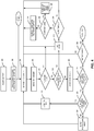
- Figure 4 illustrates a method for operating a thermoelectric refrigeration system 10 when powered on or during pull down operation according to some embodiments of the present disclosure.
- pull down operation refers to the situation where the temperature in a cooling chamber 12 is higher than is acceptable and the controller 16 operates to reduce the temperature to an acceptable range.
- the desired temperature for the cooling chamber 12 is referred to as the set point temperature.
- Steady state operation refers to the situation where the temperature of the cooling chamber 12 is within a range that includes the set point temperature. This range provides a form of hysteresis to avoid the rapid oscillation between operating states.
- the set point temperature may be 4 °C
- the steady state range may be from 3 °C to 5 °C. If maintaining the set point temperature with greater precision is desired, then the steady state range may be smaller. If a decrease in the rate of oscillation between operating states is desired, then the steady state range may be smaller.
- Figure 4 begins with a power on or reset of the thermoelectric refrigeration system 10 (step 200).
- the thermoelectric refrigeration system 10 starts in this powered on or reset state during pull down operation because the temperature may be above the steady state range and due to be powered off.
- the controller 16 reads the set point register perhaps from a user interface on the front of the thermoelectric refrigeration system 10 or from a device Graphical User Interface (GUI) to determine the set point temperature (step 202).
- the controller 16 measures the temperature control and the ⁇ T of the at least one TEM 22 (step 204).
- ⁇ T of a TEM 22 refers to the difference between the temperature of the hot side of the TEM 22 and the temperature of the cold side of the TEM 22.
- the controller 16 also measures the ambient temperature (step 206).
- the controller 16 may also determine any other system parameters that are necessary, depending on the implementation.
- the controller 16 then performs a few safety checks according to some embodiments.
- the controller 16 checks if the ambient temperature is greater than or equal to 4 °C (step 208). If the ambient temperature is less than 4 °C, the procedure returns to step 204 to again measure the various system parameters. If the ambient temperature is at least 4 °C, then the controller 16 then determines if the temperature of the heat exchanger is greater than or equal to a maximum limit (step 210).
- this temperature is the same as the temperature of the hot side of the TEM 22. Also, in some embodiments, instead of having a single maximum value, there is instead a test of whether the temperature is above a first threshold, and then when the hot side of the TEM 22 cools down there is a test of whether the temperature is below a second threshold. In this way, hysteresis can be optionally built into the overheating condition.
- the first threshold indicates that the hot side of the TEM 22 is saturated and cannot accept any additional heat.
- the first threshold might indicate that the TEM 22 may be damaged by being operated at temperatures above the first threshold. Such high temperatures might occur when a large amount of heat is removed from the cooling chamber 12 or if the TEM 22 is being operated less efficiently. An accumulation of heat on the hot side of the TEM 22 may also occur when the reject side of the heat exchanger is insufficient to remove the heat at a faster rate than the heat is generated. This situation might occur when the hot side of the TEM 22 is passively cooled.
- the controller 16 sets an alarm (step 212).
- This alarm can take many forms depending on the embodiment. In some cases, the alarm is merely an internal state; while in other cases, the information may be presented on a display, or a user may be otherwise notified of the alarm.
- the controller 16 determines if output to the TEM 22 is enabled (step 214). If output is not enabled, the controller 16 may not have any way of reducing the temperature of the hot side of the TEM 22 since no heat is being added by the operation of the TEM 22. In this case, the procedure returns to step 204 to again measure the various system parameters. In other embodiments, the controller 16 may have additional options for reducing the temperature of the hot side of the TEM 22 such as by using an active device such as a fan.
- the controller 16 determines if the amount of power being provided to the TEM 22 is the minimum power level (step 216). If it is not the minimum power level, the controller 16 decreases the amount of power provided to the TEM 22 by decrementing the output (step 218). If the current amount of power provided is the minimum power level, then the controller 16 powers off the output and issues a reset (step 220). Either way, the procedure returns to step 204 to again measure the various system parameters.
- the controller 16 clears any alarms that may be set (step 222). For instance, if an alarm had previously been set because of an overheating situation that has now been resolved, then that alarm will be cleared now.
- the controller 16 now determines if the temperature of the cooling chamber 12 is greater than an upper steady state limit (step 224). If the temperature is above the upper steady state limit, the thermoelectric refrigeration system 10 is considered to be in a pull down mode of operation.
- the controller 16 will set the output to 100%, providing the amount of power to the TEM 22 that is at or near a maximum amount of power for the TEM 22 (step 228). In such a way, the thermoelectric refrigeration system 10 can pull down the temperature of the cooling chamber 12 at the fastest rate, according to some embodiments. If the temperature of the cooling chamber 12 is determined to be less than the upper control limit, the controller 16 with set the output to proportional mode (step 230). In proportional mode, the temperature of the cooling chamber 12 may be decreased in a slower, more efficient manner. Either way, the procedure returns to step 204 to again measure the various system parameters.
- the controller 16 determines if output is enabled (step 232). If output is not enabled, the procedure returns to step 204 to again measure the various system parameters. If output is enabled, the thermoelectric refrigeration system 10 is considered to be operating in steady state mode and the procedure continues on Figure 5 which illustrates a method for operating a thermoelectric refrigeration system 10 near steady state operation according to some embodiments of the present disclosure.
- the controller 16 measures the temperature control and the ⁇ T of the at least one TEM 22 (step 300).
- the controller 16 also determines any other system parameters that are necessary, such as the ambient temperature, depending on the implementation.
- the controller 16 determines if the temperature of the heat exchanger is greater than or equal to a maximum limit (step 302). If the amount of power being provided to the TEM 22 is not the minimum power level (step 304), the controller 16 decreases the amount of power provided to the TEM 22 by decrementing the output (step 306). If the current amount of power provided is the minimum power level, then the controller 16 powers off the output and issues a reset (step 308). Either way, the procedure returns to step 300 to again measure the various system parameters.
- the controller 16 checks whether the temperature of the cooling chamber 12 is greater than the set point temperature (step 310). If the temperature of the cooling chamber 12 is less than the set point temperature, the controller 16 now determines if the temperature of the cooling chamber 12 is less than or equal to the steady state limit, the output is on, and ⁇ T is in the current band (step 312). If all of these are true, the controller 16 powers off the TEM 22 and decreases the output to 0.x Volts, stores this value in the new steady state output value, and stores the previous value in the old steady state output value (step 314). If not all of these conditions are true, then the procedure returns to step 304 and attempts to decrease the amount of power provided to the TEM 22.
- the controller 16 determines if the temperature of the cooling chamber 12 is also greater than or equal to the steady state limit (step 316). If the temperature of the chamber is less than the steady state limit, the controller determines if the timer int has been set (step 318). If it has been set, the controller 16 sets the output to the old steady state output (step 320). After this, or if it has not been set, the procedure returns to step 300 to again measure the various system parameters.
- the controller 16 determines if the temperature of the chamber is greater than or equal to the upper control limit (step 322). If the chamber is greater than or equal to the upper control limit, the controller 16 will set the output to 100%, providing the amount of power to the TEM 22 that is at or near a maximum amount of power for the TEM 22 (step 324). This indicates that the thermoelectric refrigeration system 10 is considered to be in a pull down mode of operation, and the procedure returns to step 204 of Figure 4 to again measure the various system parameters.
- the controller 16 will determine if the temperature of the cooling chamber 12 is greater than or equal to the hysteresis value (step 326). If it is not, the controller 16 increases the output to a new steady state output value (step 328), and the procedure returns to step 300 to again measure the various system parameters. According to some embodiments, this new steady state output value may be the amount of power that would maximize the COP of the TEM 22 based on one or more system parameters. If the temperature of the cooling chamber 12 is greater than or equal to the hysteresis value, this again indicates that the thermoelectric refrigeration system 10 is considered to be in a pull down mode of operation, and the procedure returns to step 204 of Figure 4 to again measure the various system parameters.
- FIG. 4 illustrates a method for operating a TEM 22 to decrease the temperature of the hot side of the TEM 22 according to some embodiments of the present disclosure.
- the controller 16 first provides a first amount of power to a TEM 22 (step 400). The controller 16 then determines if the temperature of the hot side of the TEM 22 is above a first threshold (step 402). As discussed previously, in some embodiments, the first threshold indicates that the hot side of the TEM 22 is saturated and cannot accept any additional heat. Also, the first threshold might indicate that the TEM 22 may be damaged by being operated at temperatures above the first threshold. If the temperature is not above the first threshold, the controller 16 continues to provide the first amount of power or operate according to any other control scheme that does not include overheating. If the temperature of the hot side of the TEM 22 is above the first threshold, the controller 16 provides a second amount of power to the TEM 22 that is less than the first amount of power (step 404). In some embodiments, this reduced power allows the temperature of the hot side of the TEM 22 to decrease while still operating the TEM 22.
- the controller 16 determines if the temperature of the hot side of the TEM 22 is below a second threshold (step 406). This indicates that the TEM 22 has cooled down sufficiently and is no longer saturated. In some embodiments, the controller 16 will then provide a third amount of power to the TEM 22 which may be equal to the first amount of power but is not necessarily equal.
- Figure 6 illustrates an embodiment where the procedure returns to step 400 and provides the first amount of power again. By increasing the power provided to the TEM 22, additional heat is able to be transferred.
- the first amount of power provided to the TEM 22 is at or near a maximum amount of power for the TEM 22. This is likely the case in a pull down mode of operation when the thermoelectric refrigeration system 10 is trying to remove heat as quickly as possible in order to reach the set point temperature. In some embodiments, the first amount of power provided to the TEM 22 is at or near the point where the COP of the TEM 22 is maximized. This is likely the case in a steady state mode of operation when the thermoelectric refrigeration system 10 is trying to remove the heat most efficiently.
- the second amount of power provided to the TEM 22 is at or near the point where the COP of the TEM 22 is maximized. In some embodiments, the second amount of power provided to the TEM 22 is at least an amount of power such that a temperature of the cooling chamber 12 does not increase. As discussed previously, in some embodiments, this mitigates heat rejection limitations of the TEM 22, especially when the hot side of the TEM 22 is passively cooled.
- Figure 7 illustrates one possible implementation of the method of Figure 6 according to some embodiments of the present disclosure.
- Figure 7 includes three lines. The top plots the temperature of the reject side (hot side) of the TEM 22. The bottom line plots the temperature of the cold side of the TEM 22. The middle line plots the power provided to the TEM 22 as the voltage applied to the TEM 22. At the beginning of the plot, the temperatures of the hot side and the cold side of the TEM 22 are similar. This may indicate that the thermoelectric refrigeration system 10 has just been powered on or that it is in pull down mode for some other reason such as being left open long enough.
- the controller 16 provides a first voltage to the TEM 22.
- the temperature of the hot side of the TEM 22 increases while the temperature of the cold side of the TEM 22 decreases.
- the first threshold for the temperature of the hot side of the TEM 22 is 50 °C.
- the controller 16 determines that the temperature of the hot side of the TEM 22 has reached 50 °C, the controller 16 reduces the power and provides a second amount of power to the TEM 22 that is less than the first amount. Because of this, less heat is being pumped to the hot side of the TEM 22 and it starts to cool down. Also, the temperature of the cold side of the TEM 22 has slowed its decrease or may be even rising slightly. This amount of power is provided to the TEM 22 until the controller 16 has determined that the hot side of the TEM 22 has cooled down enough.
- the controller 16 determines that the temperature of the hot side of the TEM 22 is below a second threshold, the controller 16 again provides the first amount of power to the TEM 22. This again causes the hot side of the TEM 22 to become overheated, but the cold side of the TEM 22 is now colder than it was when the hot side of the TEM 22 was last saturated.
- the controller 16 can continue this action of going between the two amounts of power to provide a quick pull down of the temperature of the cooling chamber 12 while mitigating heat rejection limitations of the TEM 22. This can be especially helpful when the hot side of the TEM 22 is passively cooled. While this example only shows two different amounts of power, the methods are not limited thereto. In some embodiments, either the larger amount of power or the smaller amount of power could be at or near the point where the COP of the TEM 22 is maximized, and this value may be recalculated each time based on the system parameters.
- the cold side temperature is tied to an insulated chamber (e.g., cooling chamber 12).
- an insulated chamber e.g., cooling chamber 12
- power to the TEM 22 is folded back to a level that will mitigate any elevation of the cold side temperature but allow the hot side temperature to decrease. This exploits the insulation of the cold side and its improved thermal stability over the hot side. Power is held reduced until the hot side temperature has lowered to a point that can allow for more heat rejection. When this point is reached, the TEM 22 power is increased, and the hot side or heat dissipation increases once again towards saturation.
- the cold side temperature will decrease since the hot side temperature is starting at a lower point.
- This cycling of power and temperature can be repeated many times to create a very slight pumping effect to augment natural convection around the hot side, allowing more overall heat to dissipate and allowing the cold side to reduce to its set point temperature.
- Figure 8 is a diagram of a controller 16 for operating a TEM 22 including a power determining module 32, a power providing module 34, and a system parameter determining module 36 according to some embodiments of the present disclosure.
- the power determining module 32, the power providing module 34, and the system parameter determining module 36 are each implemented in software that, when executed by a processor of the controller 16, causes the controller 16 to operate according to one of the embodiments described herein.
- FIG 9 is another diagram of a controller 16 for operating a TEM 22 including a power providing module 38 and a temperature determining module 40 according to some embodiments of the present disclosure.
- the power providing module 38 and the temperature determining module 40 are each implemented in software that, when executed by a processor of the controller 16, causes the controller 16 to operate according to one of the embodiments described herein.
Description
- The present disclosure relates to operation of a thermoelectric module.
- Today, many refrigeration systems are vapor compression based and utilize a thermostatically regulated duty cycle control. However, typical vapor compression based refrigeration systems are not dynamic enough to meet both the steady state and transient demand, such as during pull down or recovery. Thus, vapor compression based refrigeration systems tend to have excess cooling capabilities that far exceed heat extraction demands required during steady state operation. While the extra capacity provided by the excess cooling capabilities allows improved pull down performance, large current surges prevalent during start-up requires higher capacity and consequently more expensive components to handle the loads. Moreover, the large current surges and loads incurred by duty cycle control excessively wear the components, thereby potentially causing premature failure. Further, by the very nature of their control, thermodynamic limits, and product performance demands, vapor compression based refrigeration systems are less efficient than optimum.
- The sub-optimum efficiency disadvantage of vapor compression based refrigeration systems relates to precisely controlling the temperature within a cooling chamber. Typically, when a temperature within a cooling chamber exceeds a certain value, the vapor compression based refrigeration system activates and continues to run until the temperature in the cooling chamber is below the certain value. Once the cooling chamber reaches a temperature below the certain value, the vapor compression based refrigeration system shuts off. Nonetheless, in addition to excessive wear as noted above, this type of control scheme will typically have a relatively large control band and a relatively large internal temperature stratification in an effort to minimize energy consumption and allow for operation in varied ambient conditions. This regime is most often utilized because throttling or capacity variation is difficult and expensive to implement into the vapor compression cycle and provides limited efficacy as volumetric efficiency falls.
- Accordingly, systems and methods are needed for precisely controlling the temperature within a cooling chamber where the efficiency of the components used to extract heat from the cooling chamber is maximized. Also, systems and methods are needed for mitigating heat rejection limitations of the components used to extract heat from the cooling chamber
US 2013/291555 discloses a method of controlling a plurality of thermoelectric coolers (TEC) to maintain a set point temperature of a cooling chamber by selectively controlling two or more subsets of TECs in the plurality of TECs based on the temperature of the chamber a controller thereof. -
US 2009/293500 A1 discloses a method of controlling a thermoelectric system and a control device which adjusts the direct current supplied to the thermoelectric module based on a temperature differential between the hot and cold side of the module and on material properties of the semi-conductor based materials in order to maximize the coefficient of performance of the thermoelectric module. - Systems and methods for operating a thermoelectric module to increase efficiency are disclosed. A method of operating a thermoelectric module in a thermoelectric refrigeration system according to the invention is defined by claim 1. A method of operating a thermoelectric module includes determining a first amount of power that would maximize a coefficient of performance of the thermoelectric module based on one or more system parameters comprising an ambient temperature of an environment that is external to the cooling chamber, and providing the first amount of power to the thermoelectric module. The method also includes determining that at least one of the one or more system parameters has changed, determining a second amount of power that would maximize the coefficient of performance of the thermoelectric module based on the one or more system parameters, and providing the second amount of power to the thermoelectric module. In some embodiments, adjusting the amount of power provided based on the one or more system parameters increases the efficiency of the thermoelectric module.
- In some embodiments, providing the first amount of power to the thermoelectric module includes providing a first amount of current to the thermoelectric module, and providing the second amount of power to the thermoelectric module includes providing a second amount of current to the thermoelectric module. In some embodiments, providing the first amount of power to the thermoelectric module includes providing a first amount of voltage to the thermoelectric module, and providing the second amount of power to the thermoelectric module includes providing a second amount of voltage to the thermoelectric module.
- According to the invention, the thermoelectric module is operative to reduce a temperature of a cooling chamber. According to an embodiment, the first amount of power and/or the second amount of power is determined based on the temperature of the cooling chamber, a temperature of a hot side of the thermoelectric module, and/or an electric property of the thermoelectric module such as the figure of merit.
- According to the invention, determining the first amount of power includes determining the first amount of power that would maximize the coefficient of performance of the thermoelectric module based on the ambient temperature of the environment that is external to the cooling chamber; determining that at least one of the one or more system parameters has changed includes determining that the temperature of the environment that is external to the cooling chamber has changed; and determining the second amount of power includes determining the second amount of power that would maximize the coefficient of performance of the thermoelectric module based on the temperature of the environment that is external to the cooling chamber.
- In some embodiments, determining the first amount of power includes determining the first amount of power that would maximize the coefficient of performance of the thermoelectric module based on the one or more system parameters using a lookup table; and determining the second amount of power includes determining the second amount of power that would maximize the coefficient of performance of the thermoelectric module based on the one or more system parameters using the lookup table.
- In some embodiments, providing the first amount of power to the thermoelectric module also includes providing the first amount of power to one subset of more than one subset of thermoelectric modules, and providing the second amount of power to the thermoelectric module also includes providing the second amount of power to the one subset of the more than one subset of thermoelectric modules.
- In some embodiments, the method also includes determining that a temperature of a hot side of the thermoelectric module is above a first threshold, and providing an amount of power to the thermoelectric module that is less than the amount of power that would maximize the coefficient of performance of the thermoelectric module based on the one or more system parameters.
- In some embodiments, the method also includes determining that the temperature of the hot side of the thermoelectric module is below a second threshold, and providing an amount of power to the thermoelectric module that is the amount of power that would maximize the coefficient of performance of the thermoelectric module based on the one or more system parameters.
- A controller for operating a thermoelectric module in a thermoelectric refrigeration system as well as a thermoelectric refrigeration system according to the invention are defined by
claims 10 and 11, respectively. The thermoelectric refrigeration system includes a cooling chamber, a heat exchanger, and a controller. The heat exchanger includes a cold side heat sink, a hot side heat sink, and a thermoelectric module disposed between the cold side heat sink and the hot side heat sink. The controller is configured to determine a first amount of power that would maximize a coefficient of performance of the thermoelectric module based on one or more system parameters comprising an ambient temperature of an environment that is external to the cooling chamber; and provide the first amount of power to the thermoelectric module. The controller is also configured to determine that at least one of the one or more system parameters has changed; determine a second amount of power that would maximize the coefficient of performance of the thermoelectric module based on the one or more system parameters; and provide the second amount of power to the thermoelectric module. - The controller for operating a thermoelectric module is adapted to determine a first amount of power that would maximize a coefficient of performance of the thermoelectric module based on one or more system parameters comprising an ambient temperature of an environment that is external to the cooling chamber; provide the first amount of power to the thermoelectric module; determine that at least one of the one or more system parameters has changed; determine a second amount of power that would maximize the coefficient of performance of the thermoelectric module based on the one or more system parameters; and provide the second amount of power to the thermoelectric module. In some embodiments, the controller is adapted to perform any method disclosed herein.
- In some embodiments, a computer program includes instructions which, when executed on at least one processor, cause the at least one processor to carry out any method disclosed herein. In some embodiments, a carrier contains the computer program where the carrier is one of an electronic signal, an optical signal, a radio signal, or a computer readable storage medium.
- In an example, which is not part of the present invention, a controller for operating a thermoelectric module includes a power determining module, a power providing module, and a system parameter determining module. The power determining module is operative to determine a first amount of power that would maximize a coefficient of performance of the thermoelectric module based on one or more system parameters and determine a second amount of power that would maximize the coefficient of performance of the thermoelectric module based on the one or more system parameters. The power providing module is operative to provide the first amount of power to the thermoelectric module and to provide the second amount of power to the thermoelectric module. The system parameter determining module is operative to determine that at least one of the one or more system parameters has changed.
- The accompanying drawing figures incorporated in and forming a part of this specification illustrate several aspects of the disclosure, and together with the description serve to explain the principles of the disclosure.
-
Figure 1 illustrates a thermoelectric refrigeration system having a cooling chamber, a heat exchanger including at least one Thermoelectric Module (TEM) disposed between a cold side heat sink and a hot side heat sink, and a controller that controls the TEM according to some embodiments of the present disclosure; -
Figure 2 illustrates a relationship between a Coefficient of Performance of a TEM and an amount of power provided to the TEM for various ambient temperatures according to some embodiments of the present disclosure; -
Figure 3 illustrates a method of operating a TEM to increase efficiency of the TEM according to some embodiments of the present disclosure; -
Figure 4 illustrates a method for operating a thermoelectric refrigeration system when powered on or during pull down operation according to some embodiments of the present disclosure; -
Figure 5 illustrates a method for operating a thermoelectric refrigeration system near steady state operation according to some embodiments of the present disclosure; -
Figure 6 illustrates a method for operating a TEM to decrease the temperature of the hot side of the TEM according to some embodiments of the present disclosure; -
Figure 7 illustrates one possible implementation of the method ofFigure 6 according to some embodiments of the present disclosure; -
Figure 8 is a diagram of a controller for operating a TEM including modules according to an example which is not part of the present invention; and -
Figure 9 is another diagram of a controller for operating a TEM including modules according to an example which is not part of the present invention. - The embodiments set forth below represent the necessary information to enable those skilled in the art to practice the embodiments and illustrate the best mode of practicing the embodiments. Upon reading the following description in light of the accompanying drawing figures, those skilled in the art will understand the concepts of the disclosure and will recognize applications of these concepts not particularly addressed herein. It should be understood that these concepts and applications fall within the scope of the accompanying claims.
- It will be understood that, although the terms first, second, etc. may be used herein to describe various elements, these elements should not be limited by these terms. These terms are only used to distinguish one element from another. For example, a first element could be termed a second element, and, similarly, a second element could be termed a first element, without departing from the scope of the present disclosure. As used herein, the term "and/or" includes any and all combinations of one or more of the associated listed items.
- Relative terms such as "below" or "above" or "upper" or "lower" or "horizontal" or "vertical" may be used herein to describe a relationship of one element, layer, or region to another element, layer, or region as illustrated in the Figures. It will be understood that these terms and those discussed above are intended to encompass different orientations of the device in addition to the orientation depicted in the Figures.
- The terminology used herein is for the purpose of describing particular embodiments only and is not intended to be limiting of the disclosure. As used herein, the singular forms "a," "an," and "the" are intended to include the plural forms as well, unless the context clearly indicates otherwise. It will be further understood that the terms "comprises," "comprising," "includes," and/or "including" when used herein specify the presence of stated features, integers, steps, operations, elements, and/or components, but do not preclude the presence or addition of one or more other features, integers, steps, operations, elements, components, and/or groups thereof.
- Unless otherwise defined, all terms (including technical and scientific terms) used herein have the same meaning as commonly understood by one of ordinary skill in the art to which this disclosure belongs. It will be further understood that terms used herein should be interpreted as having a meaning that is consistent with their meaning in the context of this specification and the relevant art and will not be interpreted in an idealized or overly formal sense unless expressly so defined herein.
-
Figure 1 illustrates athermoelectric refrigeration system 10 having a coolingchamber 12, aheat exchanger 14 including at least one Thermoelectric Module (TEM) 22 (referred to herein singularly as TEM 22 or plural as TEMs 22) disposed between a coldside heat sink 20 and a hotside heat sink 18, and acontroller 16 that controls the TEM 22 according to some embodiments of the present disclosure. When a TEM 22 is used to provide cooling it may sometimes be referred to as a Thermoelectric Cooler (TEC) 22. - The TEMs 22 are preferably thin film devices. When one or more of the TEMs 22 are activated by the
controller 16, the activated TEMs 22 operate to heat the hotside heat sink 18 and cool the coldside heat sink 20 to thereby facilitate heat transfer to extract heat from the coolingchamber 12. More specifically, when one or more of the TEMs 22 are activated, the hotside heat sink 18 is heated to thereby create an evaporator and the coldside heat sink 20 is cooled to thereby create a condenser, according to some embodiments of the current disclosure. - Acting as a condenser, the cold
side heat sink 20 facilitates heat extraction from the coolingchamber 12 via an acceptloop 24 coupled with the coldside heat sink 20. The acceptloop 24 is thermally coupled to aninterior wall 26 of thethermoelectric refrigeration system 10. Theinterior wall 26 defines the coolingchamber 12. In one embodiment, the acceptloop 24 is either integrated into theinterior wall 26 or integrated directly onto the surface of theinterior wall 26. The acceptloop 24 is formed by any type of plumbing that allows for a cooling medium (e.g., a two-phase coolant) to flow or pass through the acceptloop 24. Due to the thermal coupling of the acceptloop 24 and theinterior wall 26, the cooling medium extracts heat from the coolingchamber 12 as the cooling medium flows through the acceptloop 24. The acceptloop 24 may be formed of, for example, copper tubing, plastic tubing, stainless steel tubing, aluminum tubing, or the like. - Acting as an evaporator, the hot
side heat sink 18 facilitates rejection of heat to an environment external to the coolingchamber 12 via areject loop 28 coupled to the hotside heat sink 18. Thereject loop 28 is thermally coupled to anouter wall 30, or outer skin, of thethermoelectric refrigeration system 10. - The thermal and mechanic processes for removing heat from the cooling
chamber 12 are not discussed further. Also, it should be noted that thethermoelectric refrigeration system 10 shown inFigure 1 is only a particular embodiment of a use and control of a TEM 22. All embodiments discussed herein should be understood to apply tothermoelectric refrigeration system 10 as well as any other use of a TEM 22. - Continuing with the example embodiment illustrated in
Figure 1 , thecontroller 16 operates to control the TEMs 22 in order to maintain a desired set point temperature within the coolingchamber 12. In general, thecontroller 16 operates to selectively activate/deactivate the TEMs 22, selectively control an amount of power provided to the TEMs 22, and/or selectively control a duty cycle of the TEMs 22 to maintain the desired set point temperature. Further, in preferred embodiments, thecontroller 16 is enabled to separately, or independently, control one or more and, in some embodiments, two or more subsets of the TEMs 22, where each subset includes one or more different TEMs 22. Thus, as an example, if there are four TEMs 22, thecontroller 16 may be enabled to separately control a first individual TEM 22, a second individual TEM 22, and a group of two TEMs 22. By this method, thecontroller 16 can, for example, selectively activate one, two, three, or four TEMs 22 independently, at maximized efficiency, as demand dictates. - It should be noted that the
thermoelectric refrigeration system 10 is only an example implementation and that the systems and methods disclosed herein are applicable to other systems as well. Also, while specific reference is made herein to thecontroller 16, it should be understood that any of the functions ascribed to thecontroller 16 could be implemented by any other controller or mechanism. - Before proceeding, a brief discussion of a cooling capacity versus an amount of power provided to a TEM 22 and efficiency versus an amount of power provided to a TEM 22 is beneficial. In this regard,
Figure 2 is a graph that illustrates cooling capacity (Q) and cooling efficiency of a TEC versus an input current of a TEC. The cooling efficiency is more specifically represented by a Coefficient of Performance (COP).Figure 2 illustrates a relationship between a Coefficient of Performance (COP) of a TEM 22 and an amount of power provided to the TEM 22 for various ambient temperatures according to some embodiments of the present disclosure. The amount of power provided to the TEM 22 may be expressed as an amount of current provided to the TEM 22 and/or an amount of voltage provided to the TEM 22. As the amount of power provided to the TEM 22 increases, the cooling capacity of the TEM 22 also increases. The amount of power that is at or near a maximum amount of power for the TEM 22 is denoted as Q max . Thus, when the TEM 22 is operating at Q max , the TEM 22 is removing the greatest amount of heat possible.Figure 2 illustrates the COP of the TEM 22 as a function of the amount of power provided to the TEM 22. For cooling applications, the COP of a TEM 22 is the ratio of heat removed over an amount of work input to the TEM 22 to remove the heat. The amount of heat, or capacity, (Q) at which the COP of the TEM 22 is maximized is denoted as QCOPmax . Thus, the efficiency, or COP, of the TEM 22 is maximized when the amount of power provided to the TEM 22 is at or near the point where the COP of the TEM 22 is maximized. - The shape of the COP curve for a TEM 22 is dependent upon variables such as operating ambient temperature (also referred to as the temperature of an environment that is external to the cooling
chamber 12 or the temperature of the environment in which the TEM 22 is operating), an amount of heat being rejected, the temperature of the cold side of the TEM 22 (also sometimes referred to as the temperature of the coolingchamber 12 when the TEM 22 is operable to cool a cooling chamber 12), the temperature of the hot side of the TEM 22, an electrical property of the TEM 22 (such as the figure of merit), and the amount of power provided to the TEM 22. When one of these system parameters changes, the COP curve of the TEM 22 may change, and therefore the amount of power that would maximize the COP of the TEM 22 based on one or more of the system parameters may also change.Figure 2 illustrates one example of this. Two COP curves are shown for a TEM 22 at ambient temperatures equal to 18 degrees Celsius (°C) and 25 °C. For simplicity, only the ambient temperature is changed while the other system parameters are fixed. In this example, when the ambient temperature changes from 18 °C to 25 °C, the overall COP of the TEM 22 decreases. Notably, the amount of power that maximizes the COP of the TEM 22 also increases. A trend line is shown that gives a linear approximation of the relationship between the ambient temperature and the amount of power that maximizes the COP of the TEM 22. This trend line is only one example and other means of modelling or interpolating (or extrapolating) the relationship could be used. - Since the precise amount of power that maximizes the COP of the TEM 22 is based on many factors that might be changing, a range of acceptable amounts of power centered at the amount of power that maximizes the COP of the TEM 22 is determined. This range is referred to as a band, and any amount of power within that band is generally considered to be the amount of power that maximizes the COP of the TEM 22. In some embodiments the band is the amount of power that maximizes the COP of the TEM 22 plus or minus 10%, but this is implementation specific and may depend on the precision of determining the amount of power that maximizes the COP of the TEM 22 and/or the shape of the COP curve.
- Since the most efficient way to operate the TEM 22 is to provide the amount of power that maximizes the COP of the TEM 22, the
controller 16 or some other means of controlling the TEM 22 should seek to determine the amount of power that maximizes the COP of the TEM 22 based on one or more system parameters. As such,Figure 3 illustrates a method of operating a TEM 22 to increase efficiency of the TEM 22 according to some embodiments of the present disclosure. Thecontroller 16 determines a first amount of power that would maximize the COP of the TEM 22 based on one or more system parameters (step 100). As discussed above, this determination may be based on many different parameters. In some embodiments, the determination is based on only one parameter, such as ambient temperature, assuming other parameters to be constant or negligible. In some embodiments, the amount of power may be determined by consulting a lookup table. Thecontroller 16 then provides the first amount of power to the TEM 22 (step 102). In this way, the TEM 22 is operating in the most efficient way for the current values of the system parameters. - The
controller 16 next determines if at least one of the system parameters has changed (step 104). In some embodiments, then check may be performed periodically while in other embodiments the determination of the change may be almost immediate. Also, if thecontroller 16 is using less than all of the system parameters to determine the amount of power, then thecontroller 16 will not need to determine when any of the unused system parameters have changed. In response to the determination that at least one of the system parameters has changed, thecontroller 16 determines a second amount of power that would maximize the COP of the TEM 22 based on the one or more system parameters (step 106). Thecontroller 16 then provides the second amount of power to the TEM 22 (step 108). In this way, thecontroller 16 can update the amount of power provided to the TEM 22 to increase the efficiency of the operation of the TEM 22. In some embodiments, the procedure optionally returns to step 104 and if one or more of the system parameters have changed, thecontroller 16 again determines an amount of power that would maximize the COP of the TEM 22. - Note that in some embodiments the updated amount of power may be calculated periodically or otherwise without the express determination that one or more of the system parameters have changed. Also, depending on the changes to the system parameters, the second amount of power may be the same or nearly the same as the first amount of power.
- While
Figure 3 illustrates a method of operating a TEM 22 to increase efficiency of the TEM 22,Figures 4 and5 illustrate methods for operating athermoelectric refrigeration system 10 which may include one or more TEMs 22 as discussed above in relation to the example shown inFigure 1 . Specifically,Figure 4 illustrates a method for operating athermoelectric refrigeration system 10 when powered on or during pull down operation according to some embodiments of the present disclosure. - As used herein, pull down operation refers to the situation where the temperature in a
cooling chamber 12 is higher than is acceptable and thecontroller 16 operates to reduce the temperature to an acceptable range. The desired temperature for the coolingchamber 12 is referred to as the set point temperature. Steady state operation refers to the situation where the temperature of the coolingchamber 12 is within a range that includes the set point temperature. This range provides a form of hysteresis to avoid the rapid oscillation between operating states. In some embodiments, the set point temperature may be 4 °C, and the steady state range may be from 3 °C to 5 °C. If maintaining the set point temperature with greater precision is desired, then the steady state range may be smaller. If a decrease in the rate of oscillation between operating states is desired, then the steady state range may be smaller. - According to some embodiments,
Figure 4 begins with a power on or reset of the thermoelectric refrigeration system 10 (step 200). Thethermoelectric refrigeration system 10 starts in this powered on or reset state during pull down operation because the temperature may be above the steady state range and due to be powered off. Thecontroller 16 reads the set point register perhaps from a user interface on the front of thethermoelectric refrigeration system 10 or from a device Graphical User Interface (GUI) to determine the set point temperature (step 202). Thecontroller 16 then measures the temperature control and the ΔT of the at least one TEM 22 (step 204). ΔT of a TEM 22 refers to the difference between the temperature of the hot side of the TEM 22 and the temperature of the cold side of the TEM 22. Thecontroller 16 also measures the ambient temperature (step 206). Thecontroller 16 may also determine any other system parameters that are necessary, depending on the implementation. - The
controller 16 then performs a few safety checks according to some embodiments. Thecontroller 16 checks if the ambient temperature is greater than or equal to 4 °C (step 208). If the ambient temperature is less than 4 °C, the procedure returns to step 204 to again measure the various system parameters. If the ambient temperature is at least 4 °C, then thecontroller 16 then determines if the temperature of the heat exchanger is greater than or equal to a maximum limit (step 210). - In some embodiments, this temperature is the same as the temperature of the hot side of the TEM 22. Also, in some embodiments, instead of having a single maximum value, there is instead a test of whether the temperature is above a first threshold, and then when the hot side of the TEM 22 cools down there is a test of whether the temperature is below a second threshold. In this way, hysteresis can be optionally built into the overheating condition.
- In some embodiments, the first threshold indicates that the hot side of the TEM 22 is saturated and cannot accept any additional heat. Also, the first threshold might indicate that the TEM 22 may be damaged by being operated at temperatures above the first threshold. Such high temperatures might occur when a large amount of heat is removed from the cooling
chamber 12 or if the TEM 22 is being operated less efficiently. An accumulation of heat on the hot side of the TEM 22 may also occur when the reject side of the heat exchanger is insufficient to remove the heat at a faster rate than the heat is generated. This situation might occur when the hot side of the TEM 22 is passively cooled. - When the overheating condition is detected, the
controller 16 sets an alarm (step 212). This alarm can take many forms depending on the embodiment. In some cases, the alarm is merely an internal state; while in other cases, the information may be presented on a display, or a user may be otherwise notified of the alarm. Thecontroller 16 then determines if output to the TEM 22 is enabled (step 214). If output is not enabled, thecontroller 16 may not have any way of reducing the temperature of the hot side of the TEM 22 since no heat is being added by the operation of the TEM 22. In this case, the procedure returns to step 204 to again measure the various system parameters. In other embodiments, thecontroller 16 may have additional options for reducing the temperature of the hot side of the TEM 22 such as by using an active device such as a fan. - If output is enabled, the
controller 16 determines if the amount of power being provided to the TEM 22 is the minimum power level (step 216). If it is not the minimum power level, thecontroller 16 decreases the amount of power provided to the TEM 22 by decrementing the output (step 218). If the current amount of power provided is the minimum power level, then thecontroller 16 powers off the output and issues a reset (step 220). Either way, the procedure returns to step 204 to again measure the various system parameters. - If the hot side of the TEM 22 is not overheated, the
controller 16 clears any alarms that may be set (step 222). For instance, if an alarm had previously been set because of an overheating situation that has now been resolved, then that alarm will be cleared now. Thecontroller 16 now determines if the temperature of the coolingchamber 12 is greater than an upper steady state limit (step 224). If the temperature is above the upper steady state limit, thethermoelectric refrigeration system 10 is considered to be in a pull down mode of operation. - If the temperature of the cooling
chamber 12 is determined to be greater than or equal to an upper control limit (step 226), thecontroller 16 will set the output to 100%, providing the amount of power to the TEM 22 that is at or near a maximum amount of power for the TEM 22 (step 228). In such a way, thethermoelectric refrigeration system 10 can pull down the temperature of the coolingchamber 12 at the fastest rate, according to some embodiments. If the temperature of the coolingchamber 12 is determined to be less than the upper control limit, thecontroller 16 with set the output to proportional mode (step 230). In proportional mode, the temperature of the coolingchamber 12 may be decreased in a slower, more efficient manner. Either way, the procedure returns to step 204 to again measure the various system parameters. - If the
controller 16 determines that the temperature of the coolingchamber 12 is less than an upper steady state limit, then thecontroller 16 determines if output is enabled (step 232). If output is not enabled, the procedure returns to step 204 to again measure the various system parameters. If output is enabled, thethermoelectric refrigeration system 10 is considered to be operating in steady state mode and the procedure continues onFigure 5 which illustrates a method for operating athermoelectric refrigeration system 10 near steady state operation according to some embodiments of the present disclosure. - As shown in
Figure 5 , thecontroller 16 measures the temperature control and the ΔT of the at least one TEM 22 (step 300). Thecontroller 16 also determines any other system parameters that are necessary, such as the ambient temperature, depending on the implementation. Again, thecontroller 16 determines if the temperature of the heat exchanger is greater than or equal to a maximum limit (step 302). If the amount of power being provided to the TEM 22 is not the minimum power level (step 304), thecontroller 16 decreases the amount of power provided to the TEM 22 by decrementing the output (step 306). If the current amount of power provided is the minimum power level, then thecontroller 16 powers off the output and issues a reset (step 308). Either way, the procedure returns to step 300 to again measure the various system parameters. - If the hot side of the TEM 22 is not overheated, the
controller 16 checks whether the temperature of the coolingchamber 12 is greater than the set point temperature (step 310). If the temperature of the coolingchamber 12 is less than the set point temperature, thecontroller 16 now determines if the temperature of the coolingchamber 12 is less than or equal to the steady state limit, the output is on, and ΔT is in the current band (step 312). If all of these are true, thecontroller 16 powers off the TEM 22 and decreases the output to 0.x Volts, stores this value in the new steady state output value, and stores the previous value in the old steady state output value (step 314). If not all of these conditions are true, then the procedure returns to step 304 and attempts to decrease the amount of power provided to the TEM 22. - If the temperature of the cooling
chamber 12 is greater than the set point temperature, thecontroller 16 determines if the temperature of the coolingchamber 12 is also greater than or equal to the steady state limit (step 316). If the temperature of the chamber is less than the steady state limit, the controller determines if the timer int has been set (step 318). If it has been set, thecontroller 16 sets the output to the old steady state output (step 320). After this, or if it has not been set, the procedure returns to step 300 to again measure the various system parameters. - If the temperature of the cooling
chamber 12 is greater than or equal to the steady state limit, thecontroller 16 determines if the temperature of the chamber is greater than or equal to the upper control limit (step 322). If the chamber is greater than or equal to the upper control limit, thecontroller 16 will set the output to 100%, providing the amount of power to the TEM 22 that is at or near a maximum amount of power for the TEM 22 (step 324). This indicates that thethermoelectric refrigeration system 10 is considered to be in a pull down mode of operation, and the procedure returns to step 204 ofFigure 4 to again measure the various system parameters. - If the chamber is less than the upper control limit, the
controller 16 will determine if the temperature of the coolingchamber 12 is greater than or equal to the hysteresis value (step 326). If it is not, thecontroller 16 increases the output to a new steady state output value (step 328), and the procedure returns to step 300 to again measure the various system parameters. According to some embodiments, this new steady state output value may be the amount of power that would maximize the COP of the TEM 22 based on one or more system parameters. If the temperature of the coolingchamber 12 is greater than or equal to the hysteresis value, this again indicates that thethermoelectric refrigeration system 10 is considered to be in a pull down mode of operation, and the procedure returns to step 204 ofFigure 4 to again measure the various system parameters. - As discussed above, overheating of the TEM 22 or the heat exchanger may cause undesired operation or be dangerous to the TEM 22. As such, both step 210 in
Figure 4 and step 302 inFigure 5 check for such an overheating condition. WhileFigures 4 and5 attempt to reduce the temperature of the TEM 22 by reducing the power and powering off the TEM 22, this may be undesirable or inefficient in some situations. As such,Figure 6 illustrates a method for operating a TEM 22 to decrease the temperature of the hot side of the TEM 22 according to some embodiments of the present disclosure. - The
controller 16 first provides a first amount of power to a TEM 22 (step 400). Thecontroller 16 then determines if the temperature of the hot side of the TEM 22 is above a first threshold (step 402). As discussed previously, in some embodiments, the first threshold indicates that the hot side of the TEM 22 is saturated and cannot accept any additional heat. Also, the first threshold might indicate that the TEM 22 may be damaged by being operated at temperatures above the first threshold. If the temperature is not above the first threshold, thecontroller 16 continues to provide the first amount of power or operate according to any other control scheme that does not include overheating. If the temperature of the hot side of the TEM 22 is above the first threshold, thecontroller 16 provides a second amount of power to the TEM 22 that is less than the first amount of power (step 404). In some embodiments, this reduced power allows the temperature of the hot side of the TEM 22 to decrease while still operating the TEM 22. - In some embodiments, the
controller 16 then determines if the temperature of the hot side of the TEM 22 is below a second threshold (step 406). This indicates that the TEM 22 has cooled down sufficiently and is no longer saturated. In some embodiments, thecontroller 16 will then provide a third amount of power to the TEM 22 which may be equal to the first amount of power but is not necessarily equal.Figure 6 illustrates an embodiment where the procedure returns to step 400 and provides the first amount of power again. By increasing the power provided to the TEM 22, additional heat is able to be transferred. - In some embodiments, the first amount of power provided to the TEM 22 is at or near a maximum amount of power for the TEM 22. This is likely the case in a pull down mode of operation when the
thermoelectric refrigeration system 10 is trying to remove heat as quickly as possible in order to reach the set point temperature. In some embodiments, the first amount of power provided to the TEM 22 is at or near the point where the COP of the TEM 22 is maximized. This is likely the case in a steady state mode of operation when thethermoelectric refrigeration system 10 is trying to remove the heat most efficiently. - In some embodiments, the second amount of power provided to the TEM 22 is at or near the point where the COP of the TEM 22 is maximized. In some embodiments, the second amount of power provided to the TEM 22 is at least an amount of power such that a temperature of the cooling
chamber 12 does not increase. As discussed previously, in some embodiments, this mitigates heat rejection limitations of the TEM 22, especially when the hot side of the TEM 22 is passively cooled. -
Figure 7 illustrates one possible implementation of the method ofFigure 6 according to some embodiments of the present disclosure.Figure 7 includes three lines. The top plots the temperature of the reject side (hot side) of the TEM 22. The bottom line plots the temperature of the cold side of the TEM 22. The middle line plots the power provided to the TEM 22 as the voltage applied to the TEM 22. At the beginning of the plot, the temperatures of the hot side and the cold side of the TEM 22 are similar. This may indicate that thethermoelectric refrigeration system 10 has just been powered on or that it is in pull down mode for some other reason such as being left open long enough. - At the beginning, the
controller 16 provides a first voltage to the TEM 22. In this example, the temperature of the hot side of the TEM 22 increases while the temperature of the cold side of the TEM 22 decreases. In this example, the first threshold for the temperature of the hot side of the TEM 22 is 50 °C. When thecontroller 16 determines that the temperature of the hot side of the TEM 22 has reached 50 °C, thecontroller 16 reduces the power and provides a second amount of power to the TEM 22 that is less than the first amount. Because of this, less heat is being pumped to the hot side of the TEM 22 and it starts to cool down. Also, the temperature of the cold side of the TEM 22 has slowed its decrease or may be even rising slightly. This amount of power is provided to the TEM 22 until thecontroller 16 has determined that the hot side of the TEM 22 has cooled down enough. - When the
controller 16 determines that the temperature of the hot side of the TEM 22 is below a second threshold, thecontroller 16 again provides the first amount of power to the TEM 22. This again causes the hot side of the TEM 22 to become overheated, but the cold side of the TEM 22 is now colder than it was when the hot side of the TEM 22 was last saturated. Thecontroller 16 can continue this action of going between the two amounts of power to provide a quick pull down of the temperature of the coolingchamber 12 while mitigating heat rejection limitations of the TEM 22. This can be especially helpful when the hot side of the TEM 22 is passively cooled. While this example only shows two different amounts of power, the methods are not limited thereto. In some embodiments, either the larger amount of power or the smaller amount of power could be at or near the point where the COP of the TEM 22 is maximized, and this value may be recalculated each time based on the system parameters. - In other words, if this is a thermosyphon-based system, the cold side temperature is tied to an insulated chamber (e.g., cooling chamber 12). At the point where heat dissipation on the hot side has saturated and the further decrease of the cold side temperature is stalled, power to the TEM 22 is folded back to a level that will mitigate any elevation of the cold side temperature but allow the hot side temperature to decrease. This exploits the insulation of the cold side and its improved thermal stability over the hot side. Power is held reduced until the hot side temperature has lowered to a point that can allow for more heat rejection. When this point is reached, the TEM 22 power is increased, and the hot side or heat dissipation increases once again towards saturation. However, during this time, the cold side temperature will decrease since the hot side temperature is starting at a lower point. This cycling of power and temperature can be repeated many times to create a very slight pumping effect to augment natural convection around the hot side, allowing more overall heat to dissipate and allowing the cold side to reduce to its set point temperature.
-
Figure 8 is a diagram of acontroller 16 for operating a TEM 22 including apower determining module 32, apower providing module 34, and a systemparameter determining module 36 according to some embodiments of the present disclosure. Thepower determining module 32, thepower providing module 34, and the systemparameter determining module 36 are each implemented in software that, when executed by a processor of thecontroller 16, causes thecontroller 16 to operate according to one of the embodiments described herein. -
Figure 9 is another diagram of acontroller 16 for operating a TEM 22 including apower providing module 38 and atemperature determining module 40 according to some embodiments of the present disclosure. Thepower providing module 38 and thetemperature determining module 40 are each implemented in software that, when executed by a processor of thecontroller 16, causes thecontroller 16 to operate according to one of the embodiments described herein. - Those skilled in the art will recognize improvements and modifications to the preferred embodiments of the present disclosure. All such improvements and modifications are considered within the scope of the claims that follow.
Claims (13)
- A method of operating a thermoelectric module in a thermoelectric refrigeration system (10) operative to reduce a temperature of a cooling chamber (12), comprising:determining (100) a first amount of power that would maximize a coefficient of performance of the thermoelectric module (22) based on one or more system parameters comprising an ambient temperature of an environment that is external to the cooling chamber;providing (102) the first amount of power to the thermoelectric module (22);determining (104) that at least one of the one or more system parameters has changed;determining (106) a second amount of power that would maximize the coefficient of performance of the thermoelectric module (22) based on the one or more system parameters; andproviding (108) the second amount of power to the thermoelectric module (22).
- The method of claim 1 wherein providing the first amount of power to the thermoelectric module comprises providing a first amount of current to the thermoelectric module and providing the second amount of power to the thermoelectric module comprises providing a second amount of current to the thermoelectric module.
- The method of claim 1 wherein providing the first amount of power to the thermoelectric module comprises providing a first amount of voltage to the thermoelectric module and providing the second amount of power to the thermoelectric module comprises providing a second amount of voltage to the thermoelectric module.
- The method of any of claims 1 through 3 wherein:
at least one of the group consisting of the first amount of power and the second amount of power is determined based on at least one of the group of the system parameters consisting of:the temperature of the cooling chamber;a temperature of a hot side of the thermoelectric module; andan electric property of the thermoelectric module such as the figure of merit. - The method of claim 4 wherein:determining the first amount of power comprises determining the first amount of power that would maximize the coefficient of performance of the thermoelectric module based on the ambient temperature of the environment that is external to the cooling chamber;determining that at least one of the one or more system parameters has changed comprises determining that the ambient temperature of the environment that is external to the cooling chamber has changed; anddetermining the second amount of power comprises determining the second amount of power that would maximize the coefficient of performance of the thermoelectric module based on the ambient temperature of the environment that is external to the cooling chamber.
- The method of any of claims 1 through 5 wherein:determining the first amount of power comprises determining the first amount of power that would maximize the coefficient of performance of the thermoelectric module based on the one or more system parameters using a lookup table; anddetermining the second amount of power comprises determining the second amount of power that would maximize the coefficient of performance of the thermoelectric module based on the one or more system parameters using the lookup table.
- The method of any of claims 1 through 6 wherein providing the first amount of power to the thermoelectric module further comprises providing the first amount of power to one subset of more than one subset of thermoelectric modules and providing the second amount of power to the thermoelectric module further comprises providing the second amount of power to the one subset of the more than one subset of thermoelectric modules.
- The method of any of claims 1 through 7 further comprising:determining that a temperature of a hot side of the thermoelectric module is above a first threshold; andproviding an amount of power to the thermoelectric module that is less than the amount of power that would maximize the coefficient of performance of the thermoelectric module based on the one or more system parameters.
- The method of claim 8 further comprising:determining that the temperature of the hot side of the thermoelectric module is below a second threshold; andproviding an amount of power to the thermoelectric module that is the amount of power that would maximize the coefficient of performance of the thermoelectric module based on the one or more system parameters.
- A controller (16) for operating a thermoelectric module (22) in a thermoelectric refrigeration system (10) operative to reduce a temperature of a cooling chamber (12), the controller comprising means for obtaining an ambient temperature that is external to the cooling chamber and adapted to:determine a first amount of power that would maximize a coefficient of performance of the thermoelectric refrigeration system based on one or more system parameters comprising an ambient temperature of an environment that is external to the cooling chamber;provide the first amount of power to the thermoelectric module;determine that at least one of the one or more system parameters has changed;determine a second amount of power that would maximize the coefficient of performance of the thermoelectric refrigeration system based on the one or more system parameters; andprovide the second amount of power to the thermoelectric module.
- A thermoelectric refrigeration system (10), comprising:a cooling chamber (12);a heat exchanger (14) comprising:a cold side heat sink (20);a hot side heat sink (18); anda thermoelectric module (22) disposed between the cold side heat sink and the hot side heat sink; anda controller (16) according to claim 10.
- A computer program comprising instructions which, when executed on at least one processor, cause the at least one processor to carry out the method according to any one of claims 1 through 9.
- A carrier containing the computer program of claim 12, wherein the carrier is one of an electronic signal, an optical signal, a radio signal, or a computer readable storage medium.
Applications Claiming Priority (3)
| Application Number | Priority Date | Filing Date | Title |
|---|---|---|---|
| US201462027080P | 2014-07-21 | 2014-07-21 | |
| US201462027083P | 2014-07-21 | 2014-07-21 | |
| PCT/US2015/041388 WO2016014574A1 (en) | 2014-07-21 | 2015-07-21 | Systems and methods for operating a thermoelectric module to increase efficiency |
Publications (2)
| Publication Number | Publication Date |
|---|---|
| EP3172502A1 EP3172502A1 (en) | 2017-05-31 |
| EP3172502B1 true EP3172502B1 (en) | 2019-11-20 |
Family
ID=53773557
Family Applications (2)
| Application Number | Title | Priority Date | Filing Date |
|---|---|---|---|
| EP15747314.1A Pending EP3172503A1 (en) | 2014-07-21 | 2015-07-21 | Systems and methods for mitigating heat rejection limitations of a thermoelectric module |
| EP15745336.6A Active EP3172502B1 (en) | 2014-07-21 | 2015-07-21 | Systems and methods for operating a thermoelectric module to increase efficiency |
Family Applications Before (1)
| Application Number | Title | Priority Date | Filing Date |
|---|---|---|---|
| EP15747314.1A Pending EP3172503A1 (en) | 2014-07-21 | 2015-07-21 | Systems and methods for mitigating heat rejection limitations of a thermoelectric module |
Country Status (6)
| Country | Link |
|---|---|
| EP (2) | EP3172503A1 (en) |
| JP (2) | JP6644762B2 (en) |
| KR (2) | KR102373262B1 (en) |
| CN (2) | CN106662379B (en) |
| ES (1) | ES2770014T3 (en) |
| WO (2) | WO2016014574A1 (en) |
Families Citing this family (2)
| Publication number | Priority date | Publication date | Assignee | Title |
|---|---|---|---|---|
| DE102017214764A1 (en) * | 2017-08-23 | 2019-02-28 | Mahle International Gmbh | Method for controlling a Peltier element |
| US11152557B2 (en) | 2019-02-20 | 2021-10-19 | Gentherm Incorporated | Thermoelectric module with integrated printed circuit board |
Family Cites Families (21)
| Publication number | Priority date | Publication date | Assignee | Title |
|---|---|---|---|---|
| JPH0257880A (en) * | 1988-08-20 | 1990-02-27 | Nippon Denso Co Ltd | Electronic refrigerator |
| JP3130787B2 (en) * | 1996-02-02 | 2001-01-31 | シーケーディ株式会社 | Liquid supply device |
| JPH10300306A (en) * | 1997-04-23 | 1998-11-13 | Matsushita Refrig Co Ltd | Thermoelectric module type electric refrigerator |
| US6345507B1 (en) * | 2000-09-29 | 2002-02-12 | Electrografics International Corporation | Compact thermoelectric cooling system |
| AU2003289570A1 (en) * | 2003-12-30 | 2005-07-21 | Lg Electronics, Inc. | Portable air conditioner |
| JP4391351B2 (en) * | 2004-07-29 | 2009-12-24 | 古河電気工業株式会社 | Cooling system |
| US20050257532A1 (en) * | 2004-03-11 | 2005-11-24 | Masami Ikeda | Module for cooling semiconductor device |
| WO2007001291A2 (en) * | 2005-06-24 | 2007-01-04 | Carrier Corporation | A device for controlling a thermo-electric system |
| WO2007080418A1 (en) * | 2006-01-16 | 2007-07-19 | Bookham Technology Plc | Temperature control system |
| US20080098750A1 (en) * | 2006-10-27 | 2008-05-01 | Busier Mark J | Thermoelectric cooling/heating device |
| US7426910B2 (en) * | 2006-10-30 | 2008-09-23 | Ford Global Technologies, Llc | Engine system having improved efficiency |
| WO2009111008A1 (en) * | 2008-03-05 | 2009-09-11 | Sheetak, Inc. | Method and apparatus for switched thermoelectric cooling of fluids |
| JP5542006B2 (en) * | 2010-08-26 | 2014-07-09 | 日本碍子株式会社 | Particulate matter detector |
| US8516832B2 (en) * | 2010-08-30 | 2013-08-27 | B/E Aerospace, Inc. | Control system for a food and beverage compartment thermoelectric cooling system |
| DE102011004610A1 (en) * | 2011-02-23 | 2014-08-21 | Behr Gmbh & Co. Kg | Method and device for setting an electric current for an electrothermal converter for controlling the temperature of an energy store |
| TR201807670T4 (en) * | 2011-07-25 | 2018-06-21 | Coway Co Ltd | Electronic temperature control apparatus and control method of this apparatus. |
| KR101849079B1 (en) * | 2011-07-25 | 2018-05-31 | 코웨이 주식회사 | Electronic temperature control apparatus, cooler using the same, heater using the same, and control method thereof |
| KR101928005B1 (en) * | 2011-12-01 | 2019-03-13 | 삼성전자주식회사 | Thermoelectric cooling packages and thermal management methods thereof |
| US8893513B2 (en) * | 2012-05-07 | 2014-11-25 | Phononic Device, Inc. | Thermoelectric heat exchanger component including protective heat spreading lid and optimal thermal interface resistance |
| US20130291555A1 (en) * | 2012-05-07 | 2013-11-07 | Phononic Devices, Inc. | Thermoelectric refrigeration system control scheme for high efficiency performance |
| JP2014052127A (en) * | 2012-09-06 | 2014-03-20 | Toshiba Corp | Peltier cooling device, and its cooling method |
-
2015
- 2015-07-21 ES ES15745336T patent/ES2770014T3/en active Active
- 2015-07-21 EP EP15747314.1A patent/EP3172503A1/en active Pending
- 2015-07-21 KR KR1020177000902A patent/KR102373262B1/en active IP Right Grant
- 2015-07-21 WO PCT/US2015/041388 patent/WO2016014574A1/en active Application Filing
- 2015-07-21 JP JP2017503141A patent/JP6644762B2/en active Active
- 2015-07-21 JP JP2017503600A patent/JP6677708B2/en active Active
- 2015-07-21 CN CN201580040135.3A patent/CN106662379B/en active Active
- 2015-07-21 WO PCT/US2015/041383 patent/WO2016014569A1/en active Application Filing
- 2015-07-21 KR KR1020177001838A patent/KR102421500B1/en active IP Right Grant
- 2015-07-21 EP EP15745336.6A patent/EP3172502B1/en active Active
- 2015-07-21 CN CN201580036216.6A patent/CN106662378B/en active Active
Non-Patent Citations (1)
| Title |
|---|
| None * |
Also Published As
| Publication number | Publication date |
|---|---|
| EP3172502A1 (en) | 2017-05-31 |
| ES2770014T3 (en) | 2020-06-30 |
| KR20170037951A (en) | 2017-04-05 |
| CN106662378B (en) | 2021-05-28 |
| KR102373262B1 (en) | 2022-03-10 |
| KR102421500B1 (en) | 2022-07-14 |
| JP6644762B2 (en) | 2020-02-12 |
| EP3172503A1 (en) | 2017-05-31 |
| CN106662379A (en) | 2017-05-10 |
| JP2017531147A (en) | 2017-10-19 |
| CN106662378A (en) | 2017-05-10 |
| JP2017523373A (en) | 2017-08-17 |
| WO2016014569A1 (en) | 2016-01-28 |
| WO2016014574A1 (en) | 2016-01-28 |
| JP6677708B2 (en) | 2020-04-08 |
| KR20170033298A (en) | 2017-03-24 |
| CN106662379B (en) | 2020-09-08 |
Similar Documents
| Publication | Publication Date | Title |
|---|---|---|
| US9593871B2 (en) | Systems and methods for operating a thermoelectric module to increase efficiency | |
| US10458683B2 (en) | Systems and methods for mitigating heat rejection limitations of a thermoelectric module | |
| US10012417B2 (en) | Thermoelectric refrigeration system control scheme for high efficiency performance | |
| US10520230B2 (en) | Enhanced heat transport systems for cooling chambers and surfaces | |
| US11530850B2 (en) | Compressor chiller systems including thermoelectric modules, and corresponding control methods | |
| EP3172502B1 (en) | Systems and methods for operating a thermoelectric module to increase efficiency | |
| RU2684346C1 (en) | Control method for device for cooling cabinet with electrical equipment | |
| CN114992949A (en) | Refrigerating and freezing device and control method thereof | |
| JP2013253706A (en) | Control device of cooling facility apparatus |
Legal Events
| Date | Code | Title | Description |
|---|---|---|---|
| STAA | Information on the status of an ep patent application or granted ep patent |
Free format text: STATUS: THE INTERNATIONAL PUBLICATION HAS BEEN MADE |
|
| PUAI | Public reference made under article 153(3) epc to a published international application that has entered the european phase |
Free format text: ORIGINAL CODE: 0009012 |
|
| STAA | Information on the status of an ep patent application or granted ep patent |
Free format text: STATUS: REQUEST FOR EXAMINATION WAS MADE |
|
| 17P | Request for examination filed |
Effective date: 20161129 |
|
| AK | Designated contracting states |
Kind code of ref document: A1 Designated state(s): AL AT BE BG CH CY CZ DE DK EE ES FI FR GB GR HR HU IE IS IT LI LT LU LV MC MK MT NL NO PL PT RO RS SE SI SK SM TR |
|
| AX | Request for extension of the european patent |
Extension state: BA ME |
|
| DAV | Request for validation of the european patent (deleted) | ||
| DAX | Request for extension of the european patent (deleted) | ||
| GRAP | Despatch of communication of intention to grant a patent |
Free format text: ORIGINAL CODE: EPIDOSNIGR1 |
|
| STAA | Information on the status of an ep patent application or granted ep patent |
Free format text: STATUS: GRANT OF PATENT IS INTENDED |
|
| INTG | Intention to grant announced |
Effective date: 20190619 |
|
| GRAS | Grant fee paid |
Free format text: ORIGINAL CODE: EPIDOSNIGR3 |
|
| GRAA | (expected) grant |
Free format text: ORIGINAL CODE: 0009210 |
|
| STAA | Information on the status of an ep patent application or granted ep patent |
Free format text: STATUS: THE PATENT HAS BEEN GRANTED |
|
| AK | Designated contracting states |
Kind code of ref document: B1 Designated state(s): AL AT BE BG CH CY CZ DE DK EE ES FI FR GB GR HR HU IE IS IT LI LT LU LV MC MK MT NL NO PL PT RO RS SE SI SK SM TR |
|
| REG | Reference to a national code |
Ref country code: GB Ref legal event code: FG4D |
|
| REG | Reference to a national code |
Ref country code: CH Ref legal event code: EP |
|
| REG | Reference to a national code |
Ref country code: IE Ref legal event code: FG4D |
|
| REG | Reference to a national code |
Ref country code: DE Ref legal event code: R096 Ref document number: 602015042066 Country of ref document: DE |
|
| REG | Reference to a national code |
Ref country code: AT Ref legal event code: REF Ref document number: 1204640 Country of ref document: AT Kind code of ref document: T Effective date: 20191215 |
|
| REG | Reference to a national code |
Ref country code: NL Ref legal event code: MP Effective date: 20191120 |
|
| REG | Reference to a national code |
Ref country code: LT Ref legal event code: MG4D |
|
| PG25 | Lapsed in a contracting state [announced via postgrant information from national office to epo] |
Ref country code: SE Free format text: LAPSE BECAUSE OF FAILURE TO SUBMIT A TRANSLATION OF THE DESCRIPTION OR TO PAY THE FEE WITHIN THE PRESCRIBED TIME-LIMIT Effective date: 20191120 Ref country code: LV Free format text: LAPSE BECAUSE OF FAILURE TO SUBMIT A TRANSLATION OF THE DESCRIPTION OR TO PAY THE FEE WITHIN THE PRESCRIBED TIME-LIMIT Effective date: 20191120 Ref country code: LT Free format text: LAPSE BECAUSE OF FAILURE TO SUBMIT A TRANSLATION OF THE DESCRIPTION OR TO PAY THE FEE WITHIN THE PRESCRIBED TIME-LIMIT Effective date: 20191120 Ref country code: NL Free format text: LAPSE BECAUSE OF FAILURE TO SUBMIT A TRANSLATION OF THE DESCRIPTION OR TO PAY THE FEE WITHIN THE PRESCRIBED TIME-LIMIT Effective date: 20191120 Ref country code: GR Free format text: LAPSE BECAUSE OF FAILURE TO SUBMIT A TRANSLATION OF THE DESCRIPTION OR TO PAY THE FEE WITHIN THE PRESCRIBED TIME-LIMIT Effective date: 20200221 Ref country code: NO Free format text: LAPSE BECAUSE OF FAILURE TO SUBMIT A TRANSLATION OF THE DESCRIPTION OR TO PAY THE FEE WITHIN THE PRESCRIBED TIME-LIMIT Effective date: 20200220 Ref country code: FI Free format text: LAPSE BECAUSE OF FAILURE TO SUBMIT A TRANSLATION OF THE DESCRIPTION OR TO PAY THE FEE WITHIN THE PRESCRIBED TIME-LIMIT Effective date: 20191120 Ref country code: BG Free format text: LAPSE BECAUSE OF FAILURE TO SUBMIT A TRANSLATION OF THE DESCRIPTION OR TO PAY THE FEE WITHIN THE PRESCRIBED TIME-LIMIT Effective date: 20200220 |
|
| PG25 | Lapsed in a contracting state [announced via postgrant information from national office to epo] |
Ref country code: HR Free format text: LAPSE BECAUSE OF FAILURE TO SUBMIT A TRANSLATION OF THE DESCRIPTION OR TO PAY THE FEE WITHIN THE PRESCRIBED TIME-LIMIT Effective date: 20191120 Ref country code: RS Free format text: LAPSE BECAUSE OF FAILURE TO SUBMIT A TRANSLATION OF THE DESCRIPTION OR TO PAY THE FEE WITHIN THE PRESCRIBED TIME-LIMIT Effective date: 20191120 Ref country code: IS Free format text: LAPSE BECAUSE OF FAILURE TO SUBMIT A TRANSLATION OF THE DESCRIPTION OR TO PAY THE FEE WITHIN THE PRESCRIBED TIME-LIMIT Effective date: 20200320 |
|
| PG25 | Lapsed in a contracting state [announced via postgrant information from national office to epo] |
Ref country code: AL Free format text: LAPSE BECAUSE OF FAILURE TO SUBMIT A TRANSLATION OF THE DESCRIPTION OR TO PAY THE FEE WITHIN THE PRESCRIBED TIME-LIMIT Effective date: 20191120 |
|
| REG | Reference to a national code |
Ref country code: ES Ref legal event code: FG2A Ref document number: 2770014 Country of ref document: ES Kind code of ref document: T3 Effective date: 20200630 |
|
| PG25 | Lapsed in a contracting state [announced via postgrant information from national office to epo] |
Ref country code: CZ Free format text: LAPSE BECAUSE OF FAILURE TO SUBMIT A TRANSLATION OF THE DESCRIPTION OR TO PAY THE FEE WITHIN THE PRESCRIBED TIME-LIMIT Effective date: 20191120 Ref country code: RO Free format text: LAPSE BECAUSE OF FAILURE TO SUBMIT A TRANSLATION OF THE DESCRIPTION OR TO PAY THE FEE WITHIN THE PRESCRIBED TIME-LIMIT Effective date: 20191120 Ref country code: DK Free format text: LAPSE BECAUSE OF FAILURE TO SUBMIT A TRANSLATION OF THE DESCRIPTION OR TO PAY THE FEE WITHIN THE PRESCRIBED TIME-LIMIT Effective date: 20191120 Ref country code: EE Free format text: LAPSE BECAUSE OF FAILURE TO SUBMIT A TRANSLATION OF THE DESCRIPTION OR TO PAY THE FEE WITHIN THE PRESCRIBED TIME-LIMIT Effective date: 20191120 Ref country code: PT Free format text: LAPSE BECAUSE OF FAILURE TO SUBMIT A TRANSLATION OF THE DESCRIPTION OR TO PAY THE FEE WITHIN THE PRESCRIBED TIME-LIMIT Effective date: 20200412 |
|
| REG | Reference to a national code |
Ref country code: AT Ref legal event code: MK05 Ref document number: 1204640 Country of ref document: AT Kind code of ref document: T Effective date: 20191120 |
|
| REG | Reference to a national code |
Ref country code: DE Ref legal event code: R097 Ref document number: 602015042066 Country of ref document: DE |
|
| PG25 | Lapsed in a contracting state [announced via postgrant information from national office to epo] |
Ref country code: SK Free format text: LAPSE BECAUSE OF FAILURE TO SUBMIT A TRANSLATION OF THE DESCRIPTION OR TO PAY THE FEE WITHIN THE PRESCRIBED TIME-LIMIT Effective date: 20191120 Ref country code: SM Free format text: LAPSE BECAUSE OF FAILURE TO SUBMIT A TRANSLATION OF THE DESCRIPTION OR TO PAY THE FEE WITHIN THE PRESCRIBED TIME-LIMIT Effective date: 20191120 |
|
| PLBE | No opposition filed within time limit |
Free format text: ORIGINAL CODE: 0009261 |
|
| STAA | Information on the status of an ep patent application or granted ep patent |
Free format text: STATUS: NO OPPOSITION FILED WITHIN TIME LIMIT |
|
| 26N | No opposition filed |
Effective date: 20200821 |
|
| PG25 | Lapsed in a contracting state [announced via postgrant information from national office to epo] |
Ref country code: SI Free format text: LAPSE BECAUSE OF FAILURE TO SUBMIT A TRANSLATION OF THE DESCRIPTION OR TO PAY THE FEE WITHIN THE PRESCRIBED TIME-LIMIT Effective date: 20191120 Ref country code: PL Free format text: LAPSE BECAUSE OF FAILURE TO SUBMIT A TRANSLATION OF THE DESCRIPTION OR TO PAY THE FEE WITHIN THE PRESCRIBED TIME-LIMIT Effective date: 20191120 Ref country code: AT Free format text: LAPSE BECAUSE OF FAILURE TO SUBMIT A TRANSLATION OF THE DESCRIPTION OR TO PAY THE FEE WITHIN THE PRESCRIBED TIME-LIMIT Effective date: 20191120 |
|
| PG25 | Lapsed in a contracting state [announced via postgrant information from national office to epo] |
Ref country code: MC Free format text: LAPSE BECAUSE OF FAILURE TO SUBMIT A TRANSLATION OF THE DESCRIPTION OR TO PAY THE FEE WITHIN THE PRESCRIBED TIME-LIMIT Effective date: 20191120 |
|
| REG | Reference to a national code |
Ref country code: CH Ref legal event code: PL |
|
| REG | Reference to a national code |
Ref country code: BE Ref legal event code: MM Effective date: 20200731 |
|
| PG25 | Lapsed in a contracting state [announced via postgrant information from national office to epo] |
Ref country code: LU Free format text: LAPSE BECAUSE OF NON-PAYMENT OF DUE FEES Effective date: 20200721 Ref country code: LI Free format text: LAPSE BECAUSE OF NON-PAYMENT OF DUE FEES Effective date: 20200731 Ref country code: CH Free format text: LAPSE BECAUSE OF NON-PAYMENT OF DUE FEES Effective date: 20200731 |
|
| PG25 | Lapsed in a contracting state [announced via postgrant information from national office to epo] |
Ref country code: BE Free format text: LAPSE BECAUSE OF NON-PAYMENT OF DUE FEES Effective date: 20200731 |
|
| PG25 | Lapsed in a contracting state [announced via postgrant information from national office to epo] |
Ref country code: IE Free format text: LAPSE BECAUSE OF NON-PAYMENT OF DUE FEES Effective date: 20200721 |
|
| PG25 | Lapsed in a contracting state [announced via postgrant information from national office to epo] |
Ref country code: TR Free format text: LAPSE BECAUSE OF FAILURE TO SUBMIT A TRANSLATION OF THE DESCRIPTION OR TO PAY THE FEE WITHIN THE PRESCRIBED TIME-LIMIT Effective date: 20191120 Ref country code: MT Free format text: LAPSE BECAUSE OF FAILURE TO SUBMIT A TRANSLATION OF THE DESCRIPTION OR TO PAY THE FEE WITHIN THE PRESCRIBED TIME-LIMIT Effective date: 20191120 Ref country code: CY Free format text: LAPSE BECAUSE OF FAILURE TO SUBMIT A TRANSLATION OF THE DESCRIPTION OR TO PAY THE FEE WITHIN THE PRESCRIBED TIME-LIMIT Effective date: 20191120 |
|
| PG25 | Lapsed in a contracting state [announced via postgrant information from national office to epo] |
Ref country code: MK Free format text: LAPSE BECAUSE OF FAILURE TO SUBMIT A TRANSLATION OF THE DESCRIPTION OR TO PAY THE FEE WITHIN THE PRESCRIBED TIME-LIMIT Effective date: 20191120 |
|
| PGFP | Annual fee paid to national office [announced via postgrant information from national office to epo] |
Ref country code: IT Payment date: 20230727 Year of fee payment: 9 Ref country code: GB Payment date: 20230729 Year of fee payment: 9 Ref country code: ES Payment date: 20230802 Year of fee payment: 9 |
|
| PGFP | Annual fee paid to national office [announced via postgrant information from national office to epo] |
Ref country code: FR Payment date: 20230725 Year of fee payment: 9 Ref country code: DE Payment date: 20230727 Year of fee payment: 9 |