EP3172396B1 - A system and method for accessing a well - Google Patents
A system and method for accessing a well Download PDFInfo
- Publication number
- EP3172396B1 EP3172396B1 EP15736245.0A EP15736245A EP3172396B1 EP 3172396 B1 EP3172396 B1 EP 3172396B1 EP 15736245 A EP15736245 A EP 15736245A EP 3172396 B1 EP3172396 B1 EP 3172396B1
- Authority
- EP
- European Patent Office
- Prior art keywords
- spool
- passage
- hanger
- valve
- longitudinal passage
- Prior art date
- Legal status (The legal status is an assumption and is not a legal conclusion. Google has not performed a legal analysis and makes no representation as to the accuracy of the status listed.)
- Active
Links
Images




Classifications
-
- E—FIXED CONSTRUCTIONS
- E21—EARTH OR ROCK DRILLING; MINING
- E21B—EARTH OR ROCK DRILLING; OBTAINING OIL, GAS, WATER, SOLUBLE OR MELTABLE MATERIALS OR A SLURRY OF MINERALS FROM WELLS
- E21B34/00—Valve arrangements for boreholes or wells
- E21B34/02—Valve arrangements for boreholes or wells in well heads
-
- E—FIXED CONSTRUCTIONS
- E21—EARTH OR ROCK DRILLING; MINING
- E21B—EARTH OR ROCK DRILLING; OBTAINING OIL, GAS, WATER, SOLUBLE OR MELTABLE MATERIALS OR A SLURRY OF MINERALS FROM WELLS
- E21B33/00—Sealing or packing boreholes or wells
- E21B33/02—Surface sealing or packing
- E21B33/03—Well heads; Setting-up thereof
-
- E—FIXED CONSTRUCTIONS
- E21—EARTH OR ROCK DRILLING; MINING
- E21B—EARTH OR ROCK DRILLING; OBTAINING OIL, GAS, WATER, SOLUBLE OR MELTABLE MATERIALS OR A SLURRY OF MINERALS FROM WELLS
- E21B33/00—Sealing or packing boreholes or wells
- E21B33/02—Surface sealing or packing
- E21B33/03—Well heads; Setting-up thereof
- E21B33/035—Well heads; Setting-up thereof specially adapted for underwater installations
- E21B33/0353—Horizontal or spool trees, i.e. without production valves in the vertical main bore
-
- E—FIXED CONSTRUCTIONS
- E21—EARTH OR ROCK DRILLING; MINING
- E21B—EARTH OR ROCK DRILLING; OBTAINING OIL, GAS, WATER, SOLUBLE OR MELTABLE MATERIALS OR A SLURRY OF MINERALS FROM WELLS
- E21B33/00—Sealing or packing boreholes or wells
- E21B33/02—Surface sealing or packing
- E21B33/03—Well heads; Setting-up thereof
- E21B33/04—Casing heads; Suspending casings or tubings in well heads
-
- E—FIXED CONSTRUCTIONS
- E21—EARTH OR ROCK DRILLING; MINING
- E21B—EARTH OR ROCK DRILLING; OBTAINING OIL, GAS, WATER, SOLUBLE OR MELTABLE MATERIALS OR A SLURRY OF MINERALS FROM WELLS
- E21B33/00—Sealing or packing boreholes or wells
- E21B33/02—Surface sealing or packing
- E21B33/03—Well heads; Setting-up thereof
- E21B33/04—Casing heads; Suspending casings or tubings in well heads
- E21B33/043—Casing heads; Suspending casings or tubings in well heads specially adapted for underwater well heads
-
- E—FIXED CONSTRUCTIONS
- E21—EARTH OR ROCK DRILLING; MINING
- E21B—EARTH OR ROCK DRILLING; OBTAINING OIL, GAS, WATER, SOLUBLE OR MELTABLE MATERIALS OR A SLURRY OF MINERALS FROM WELLS
- E21B33/00—Sealing or packing boreholes or wells
- E21B33/02—Surface sealing or packing
- E21B33/03—Well heads; Setting-up thereof
- E21B33/04—Casing heads; Suspending casings or tubings in well heads
- E21B33/047—Casing heads; Suspending casings or tubings in well heads for plural tubing strings
-
- E—FIXED CONSTRUCTIONS
- E21—EARTH OR ROCK DRILLING; MINING
- E21B—EARTH OR ROCK DRILLING; OBTAINING OIL, GAS, WATER, SOLUBLE OR MELTABLE MATERIALS OR A SLURRY OF MINERALS FROM WELLS
- E21B33/00—Sealing or packing boreholes or wells
- E21B33/02—Surface sealing or packing
- E21B33/03—Well heads; Setting-up thereof
- E21B33/068—Well heads; Setting-up thereof having provision for introducing objects or fluids into, or removing objects from, wells
-
- E—FIXED CONSTRUCTIONS
- E21—EARTH OR ROCK DRILLING; MINING
- E21B—EARTH OR ROCK DRILLING; OBTAINING OIL, GAS, WATER, SOLUBLE OR MELTABLE MATERIALS OR A SLURRY OF MINERALS FROM WELLS
- E21B33/00—Sealing or packing boreholes or wells
- E21B33/02—Surface sealing or packing
- E21B33/03—Well heads; Setting-up thereof
- E21B33/035—Well heads; Setting-up thereof specially adapted for underwater installations
Definitions
- oil and natural gas have a profound effect on modern economies and societies. Indeed, devices and systems that depend on oil and natural gas are ubiquitous. For instance, oil and natural gas are used for fuel in a wide variety of vehicles, such as cars, airplanes, boats, and the like. Further, oil and natural gas are frequently used to heat homes during winter, to generate electricity, and to manufacture an astonishing array of everyday products.
- drilling and production systems are often employed to access and extract the resource.
- These systems may be located onshore or offshore depending on the location of a desired resource.
- Such systems generally include a wellhead assembly through which the resource is extracted.
- These wellhead assemblies may include a wide variety of components, such as various casings, hangers, valves, fluid conduits, and the like, that control drilling and/or extraction operations.
- WO2013/027081 A1 disclose systems for accessing a well.
- US 2007/204999 describes a completion suspension valve system which allows a well to be suspended and de-suspended remotely without a dual bore riser to the surface. This is achieved by incorporating a remotely actuatable valve into the production bore of a tubing hanger.
- the valve is hydraulically operable and may be controlled via the tubing hanger running tool or via the Xmas tree. The valve can be closed and tested after the tubing hanger has been installed, thereby isolating the well.
- the dual bore riser and running tool are retrievable.
- Various arrangements of production control valves may be coupled to a wellhead in an assembly generally known as a tree, such as a vertical tree or a horizontal tree.
- a vertical tree With a vertical tree, after the tubing hanger and production tubing are installed in the high pressure wellhead housing or a spool such as a tubing spool, a blowout prevent (BOP) may be removed and the vertical tree may be locked and sealed onto the wellhead.
- BOP blowout prevent
- the vertical tree includes one or more production passages containing actuated valves that extend vertically to respective lateral production fluid outlets in the vertical tree. The production passages and production valves are thus in-line with the production tubing.
- the tree With a vertical tree, the tree may be removed while leaving the completion (e.g., the production tubing and hanger) in place.
- the completion e.g., the production tubing and hanger
- the vertical tree must be removed and replaced with a BOP, which involves setting and testing plugs or relying on down-hole valves, which may be unreliable due to lack of use and/or testing.
- removal and installation of the tree and BOP assembly generally requires robust lifting equipment, such as a rig, that may have high daily rental rates, for instance.
- the well is also in a vulnerable condition while the vertical tree and BOP are being exchanged and neither of these pressure-control devices is in position.
- trees with the arrangement of production control valves offset from the production tubing may be utilized.
- a spool tree also locks and seals onto the wellhead housing.
- the tubing hanger instead of being located in the wellhead, locks and seals in the tree passage.
- a production passage extends through the tubing hanger, and seals to prevent fluid leakage, thereby facilitating a flow of production fluid into a corresponding production passage in the tree.
- a locking mechanism above the production seals locks the tubing hanger in place in the tree.
- the production tubing hanger and production tubing may be removed from the tree without having to remove the spool tree from the wellhead housing.
- the entire completion must also be removed, which takes considerable time and also involves setting and testing plugs or relying on down-hole valves, which may be unreliable due to lack of use and/or testing.
- the locking mechanism on the tubing hanger is above and blocks access to the production port seals, the entire completion must be pulled to service the seals.
- an operator may select equipment best suited for the expected type of maintenance. For example, a well operator may predict whether there will be a greater need in the future to pull the tree from the well for repair, or pull the completion, either for repair or for additional work in the well. Depending on the predicted maintenance events, an operator will decide whether the horizontal or vertical tree, each with its own advantages and disadvantages, is best suited for the expected conditions. For instance, with a vertical tree, it is more efficient to pull the tree and leave the completion in place. However, if the completion needs to be pulled, the tree must be pulled as well, increasing the time and expense of pulling the completion. Conversely, with a spool tree, it is more efficient to pull the completion, leaving the tree in place.
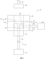
- FIG. 1 is a block diagram that illustrates an exemplary well completion system 10 that does not fall within the scope of the present invention.
- the illustrated well completion system 10 can be configured to extract various minerals and natural resources, including hydrocarbons (e.g., oil and/or natural gas), or configured to inject substances into the earth.
- the well completion system 10 is land-based (e.g., a surface system) or subsea (e.g., a subsea system).
- the system 10 is a subsea system that includes a wellhead 12 coupled to a mineral deposit 14 via a well 16, wherein the well 16 includes a wellhead hub 18, which can be a high pressure wellhead housing and a well bore 20.
- the wellhead hub 18 generally includes a large diameter hub that is disposed at the termination of the well bore 20.
- the wellhead hub 18 provides for the connection of the wellhead 12 to the well 16.
- the well completion system 10 may also be used as surface system.
- the wellhead 12 typically includes multiple components that control and regulate activities and conditions associated with the well 16.
- the wellhead 12 generally includes bodies, valves, and seals that route produced minerals from the mineral deposit 14, provide for regulating pressure in the well 16, and provide for the injection of chemicals into the well bore 20 (downhole).
- the wellhead 12 includes a subsea tree 22, a spool 24 (e.g., a tubing spool), and a tubing hanger 26.
- the system 10 may include other devices that are coupled to the wellhead 12, and devices that are used to assemble and control various components of the wellhead 12.
- the system 10 includes a tubing hanger running tool (THRT) 28 suspended from a drill string 30.
- THRT tubing hanger running tool
- the THRT 28 is lowered (e.g., run) from an offshore vessel to the well 16 and/or the wellhead 12.
- a blowout preventer (BOP) 32 may also be included, and may include a variety of valves, fittings and controls to block oil, gas, or other fluid from exiting the well in the event of an unintentional release of pressure or an overpressure condition.
- the spool 24 is coupled to the wellhead hub 18.
- the spool 24 is one of many components in a modular subsea or surface completion system 10 that is run from an offshore vessel or surface system.
- the spool 24 includes a longitudinal passage 34 configured to support the tubing hanger 26.
- the passage 34 may provide access to the well bore 20 for various completion and workover procedures.
- components can be run down to the wellhead 12 and disposed in the spool passage 34 to seal-off the well bore 20, to inject chemicals down-hole, to suspend tools down-hole, to retrieve tools down-hole, and the like.
- the well bore 20 may contain elevated pressures.
- the well bore 20 may include pressures that exceed 70 MPa (10,000 pounds per square inch (PSI)), that exceed 103 MPa (15,000 PSI), and/or that even exceed 140 MPa (20,000 PSI).
- well completion systems 10 employ various mechanisms, such as mandrels, seals, plugs and valves, to control and regulate the well 16.
- the illustrated tubing hanger 26 is typically disposed within the wellhead 12 to secure tubing suspended in the well bore 20, and to provide a path for hydraulic control fluid, chemical injections, and the like.
- the hanger 26 includes a longitudinal bore 36 that extends through the center of the hanger 26, and that is in fluid communication with the well bore 20. As illustrated in the example of FIG.
- the hanger 26 also includes a lateral flow passage 38 in fluid communication with the longitudinal passage 36.
- the lateral flow passage 38 of the tubing hanger 26 is configured to transfer product (e.g., oil, natural gas, etc.) from the longitudinal tubing hanger passage 36 to a lateral flow passage 40 of the spool 24.
- the lateral flow passage 40 of the spool 24 extends from the longitudinal spool passage 34 to a hub connection 42.
- the hub connection 42 is configured to interface with a mating hub connection 44 of the subsea tree 22, thereby establishing a flow path from the longitudinal passage 36 of the tubing hanger 26 through the lateral flow passages 38 and 40 and into the subsea tree 22. While the interface between the hub connection 42 and the mating hub connection 44 is oriented along a plane substantially parallel to the longitudinal passage 34 of the spool 24, it should be appreciated that alternative examples may employ an interface along a plane substantially perpendicular to the longitudinal passage 34.
- FIG. 2 is a cross-sectional side view of an example of a spool 24 and subsea tree 22 that does not fall within the scope of the present invention and that may be used in the completion system 10.
- the spool 24 is configured to be positioned between the wellhead hub 18 and the BOP 32. Consequently, the spool 24 includes a first end 46 configured to interface with the wellhead hub 18, and a second end 48 configured to interface with the BOP 32.
- the longitudinal passage 34 extends in an axial direction 45 between the first end 46 and the second end 48, thereby establishing a flow path through the spool 24.
- a collet connector 50 serves to secure the first end 46 of the spool 24 to the wellhead hub 18.
- a cap 52 (e.g., an internal tree cap) is disposed within the longitudinal passage 34 between the tubing hanger 26 and the second end 48 to block fluid flow into and out of the spool 24.
- the cap 52 includes a fluid barrier 54, such as a wireline plug, and a seal 56, such as a rubber o-ring, for example. More than one fluid barrier 54 may also be used.
- the cap 52 may include a locking mechanism configured to secure the cap 52 to the longitudinal passage 34 of the spool 24. Consequently, the cap 52 may be retrieved by releasing the locking mechanism, and then extracting the cap 52 from the passage 34.
- the plug may be removable (e.g., via a wireline) to provide fluid communication with the longitudinal passage 34.
- the fluid barrier 54 may be an adjustable barrier, such as an actuatable valve.
- the valve may be any suitable valve, such as by non-limiting example, a ball valve, a sliding sleeve valve, a shuttle valve, or a gate valve.
- the adjustable barrier(s) can thus open and close a longitudinal passage running through the cap 52 to allow mechanical and circulation access through the cap during workover operations, without having to pull plugs in the cap 52.
- More than one fluid barrier 54 may also be used in the cap 52 and the fluid barriers 54 may be different types, such as one plug and one valve.
- the tubing hanger 26 is configured to support a tubing string 57 that extends down the well bore 20 to the mineral deposit 14.
- an annulus 58 of the spool 24 surrounds the tubing string 57 and may be filled with completion fluid.
- a fluid barrier 60 such as a plug or an adjustable barrier, is disposed within the longitudinal passage 36 of the tubing hanger 26 and serves as a barrier between the product extracted from the mineral deposit 14 and the completion fluid within the annulus 58.
- the tubing hanger 26 may also include a profile for installing a fluid barrier 60 in the hanger longitudinal passage 36.
- a fluid barrier 60 such as a plug or an actuatable valve may be interchangeable in the profile. More than one barrier 60 may also be used.
- the barrier 60 may block the flow of fluid up through the top of the tubing hanger 26.
- the barrier 60 may be an adjustable barrier such as an actuatable valve.
- the valve may be any suitable valve, such as by non-limiting example, a ball valve, a sliding sleeve valve, a shuttle valve, or a gate valve.
- the valve may be actuated electrically, hydraulically, mechanically, or by any other suitable means. More than one barrier 60 may also be used.
- the valve can thus open and close the longitudinal passage 36 of the tubing hanger 26 to allow direct downhole mechanical and circulation access during workover operations, without having to pull crown plugs in the tubing hanger 26.
- At least one of the barriers 54, 60 is an adjustable barrier. If a barrier 54 or 60 is not an adjustable barrier, it is a non-adjustable barrier, such as a removable plug. Any combination of barriers where at least one of the barriers is adjustable may be used. For example, all of the barriers 54, 60 may be adjustable barriers.
- the tubing hanger 26 includes a seal 62 (e.g., rubber o-ring) disposed against the longitudinal passage 34 of the spool 24 and configured to block fluid flow around the tubing hanger 26.
- the illustrated wellhead configuration also includes an isolation sleeve 64 disposed within the passage 34 and extending from the first end 46 of the spool 24 to the wellhead hub 18.
- the isolation sleeve 64 includes a first seal 66 (e.g., rubber o-ring) in contact with the passage of the wellhead hub 18, and a second seal 68 (e.g., rubber o-ring) in contact with the passage 34 of the spool 24.
- the isolation sleeve 64 may facilitate pressure testing of the seal between the wellhead hub 18 and the spool 24.
- the isolation sleeve 64 may also serve as an additional barrier to block a flow of completion fluid from exiting the wellhead 12 through the interface between the spool 24 and the wellhead hub 18.
- the tubing hanger 26 includes a first seal 70 positioned adjacent to the passage 34 of the spool 24 and located in a downward direction 71 from the lateral flow passage 38.
- the tubing hanger 26 also includes a second seal 72 positioned adjacent to the passage 34 and located in an upward direction 73 from the lateral flow passage 38.
- the seals 70 and 72 are configured to block flow of completion fluid into the lateral flow passage 38, and to block flow of product (e.g., oil and/or natural gas) into the annulus 58. Consequently, a flow path will be established between the tubing string 57 and the lateral flow passage 40 of the spool 24, thereby facilitating the flow of product to the subsea tree 22.
- product will flow from the tubing string 57 in the upward direction 73 into the longitudinal passage 36 of the tubing hanger 26. Because the actuatable valve 60 blocks the flow of product from exiting the top of the tubing hanger 26, the product will be directed through the lateral flow passage 38 of the tubing hanger 26 and into the lateral flow passage 40 of the spool 24. The product will then flow into the subsea tree 22 via the interface between the hub connection 42 and the mating hub connection 44. While the actuatable valve 60 serves to block the flow of product out of the top of the tubing hanger 26, it should be appreciated that the plug 54 within the cap 52 serves as a backup seal to block product from exiting the spool 24, thereby providing a dual barrier between the product and the environment.
- the spool 24 includes one or more valves 74, such as production valves, coupled to the lateral flow passage 40. As shown, the spool includes both production valves 74 but it should also be appreciated that only one production valve 74 may be included. It should also be appreciated that the term "production" as used to describe valve 74 is for convenience and that the valve 74 may be used to regulate flow in either direction and for injection as well as production.
- the production valves 74 are configured to control the flow of product between the spool 24 and the tree 22. For example, one or both of the production valves 74 may be closed prior to retrieving the tree 22, thereby blocking the flow of product from entering the environment.
- valves 74 may be opened to facilitate product flow to the subsea tree 22.
- two production valves 74 are used and both in respective closed positions, two barriers are provided between the product flow and the environment, even when the tree 22 is removed.
- the present example includes valves 74, it should be appreciated that alternative examples may employ any suitable device (e.g., wireline plug) configured to substantially block production flow from the well 16 to the hub connection 42.
- the hub connection 42 coupled to the mating hub connection 44
- the lateral flow passage 40 of the spool 24 is in fluid communication with a product flow passage 75 of the subsea tree 22.
- the hub connection 42 is coupled to the mating hub connection 44 with a clamp 77, such as a manual clamp or a hydraulic connector.
- the product flow passage 75 includes a first valve 76 and a second valve 78. As illustrated in FIG. 2 , the first valve 76 is positioned upstream of an annulus crossover valve 80, and the second valve 78 is positioned downstream from the annulus crossover valve 80. Valves 76 and 78 may be first and second production valves. As discussed in detail below, the valves 76, 78 and 80 may be controlled to vary fluid flow into and out of the annulus 58 and tubing string 57. In addition, the product flow passage 75 includes a choke 82 positioned downstream from the valves 76 and 78 and configured to regulate pressure and/or flow rate of product through the flow passage 75.
- the flow passage 75 also includes a flowline isolation valve 84 configured to selectively block fluid flow between the tree 22 and the surface. As illustrated, the product flow passage 75 terminates at a flowline hub 86 configured to interface with a conduit or manifold that conveys the product from the wellhead 12 to a surface vessel or platform.
- the spool 24 includes an upper annulus flow passage 88 and a lower annulus flow passage 90 to regulate completion fluid pressure within an upper region 89 above the tubing hanger 26 and a lower region 91 below the tubing hanger 26, respectively.
- the upper annulus flow passage 88 extends from the upper region 89 to a lateral flow passage 92
- the lower annulus flow passage 90 extends from the lateral flow passage 92 to the lower region 91.
- completion fluid may be supplied and/or removed from each region 89 and 91 of the annulus 58.
- the upper annulus flow passage 88 includes an upper annulus valve 94
- the lower annulus flow passage 90 includes a lower annulus valve 96.
- the valves 94 and 96 are configured to control fluid flow to the upper region 89 and lower region 91, respectively.
- the lateral annulus flow passage 92 extends through the hub connection 42 and interfaces with an annulus flow passage 97 of the subsea tree 22, thereby establishing a completion fluid flow path between the spool 24 and the subsea tree 22.
- the annulus flow passage 97 includes an annulus valve 98 positioned upstream of the annulus crossover valve 80, and an annulus monitor valve 100 positioned downstream from the annulus crossover valve 80.
- the annulus valves 98 and 100 may be controlled along with the valves 76 and 78 and the annulus crossover valve 80 to adjust fluid flow to and from the annulus 58 and the tubing string 57.
- the tubing hanger 26 includes a valve 63, or other closure element below the lateral flow passage 38.
- the valve 63 is configured to selectively block product flow to the subsea tree 22 and may be operated hydraulically or otherwise.
- the valve 63 may also be included in a sub or other extension below the tubing hanger 26.
- the valve 63 works together with the barrier 60 but also with the valve 102 (discussed below) to provide an environmental barrier to fluid flow, such as production fluid flow, when either the subsea tree 22 or the cap 52 are not installed.
- the tubing string 57 includes a downhole valve 102, such as for example a surface-controlled subsurface safety valve (SCSSV) 102 configured to selectively block product flow to the subsea tree 22.
- a downhole valve 102 such as for example a surface-controlled subsurface safety valve (SCSSV) 102 configured to selectively block product flow to the subsea tree 22.
- SCSSV surface-controlled subsurface safety valve
- the valve 102 may be hydrauhcally operated and biased toward a closed position (i.e., failsafe closed) to ensure that the SCSSV closes if the system experiences a reduction in hydraulic pressure.
- a closed position i.e., failsafe closed
- the SCSSV 102 is hydrauhcally controlled via a conduit 104 extending from the hub connection 42 to the SCSSV 102.
- the conduit 104 connects with a conduit 110 within the subsea tree 22 when the hub connection 42 is mounted to the mating hub connection 44, , thereby establishing a fluid connection between the conduit 104 within the spool 24 and the conduit 110 within the subsea tree 22.
- the connection may be any type of sealing connection, such as a stab connection.
- the connection may also be configured to substantially block fluid flow into and out of the respective conduits 104 and 110 when disengaged.
- the conduit 110 is coupled to a valve 112 configured to selectively block hydraulic fluid flow to the downhole valve 102.
- the spool 24 also includes a vent/test conduit 114 configured to regulate fluid flow to certain regions of the tubing hanger 26.
- the conduit 114 connects with a conduit 120 within the subsea tree 22 when the hub connection 42 is mounted to the mating hub connection 44, thereby establishing a fluid connection between the conduit 114 within the spool 24 and the conduit 120 within the subsea tree 22.
- the connection may be any type of sealing connection, such as a stab connection.
- the connection may also be configured to substantially block fluid flow into and out of the respective conduits 114 and 120 when disengaged.
- the conduit 120 is coupled to a valve 122 configured to selectively block fluid flow to the vent/test conduit 114.
- the spool 24 also includes a chemical injection conduit 124 configured to inject chemicals, such as methanol, polymers, surfactants, etc., into the well bore 20 to improve recovery.
- the conduit 124 connects with a conduit 130 within the subsea tree 22 when the hub connection 42 is mounted to the mating hub connection 44, thereby establishing a fluid connection between the conduit 124 within the spool 24 and the conduit 130 within the subsea tree 22.
- the connection may be any type of sealing connection, such as a stab connection.
- the connection may also be configured to substantially block fluid flow into and out of the respective conduits 124 and 130 when disengaged.
- the conduit 130 is coupled to a valve 132 configured to selectively block the flow of chemicals into the well bore 20.
- the spool 24 also includes another hydraulic conduit 134 configured to operate a sliding sleeve within the tubing string 57.
- the tubing string 57 may terminate in a first region of the mineral deposit 14 and the sliding sleeve may be aligned with a second region of the mineral deposit 14.
- the tubing string 57 may extract product from the first region.
- the sliding sleeve is in an open position, the tubing string 57 may extract product from the second region. Consequently, product may be selectively extracted from various regions of the mineral deposit 14 with a single tubing string 57.
- the conduit 134 connects with a conduit 140 within the subsea tree 22 when the hub connection 42 is mounted to the mating hub connection 44, thereby establishing a fluid connection between the conduit 134 within the spool 24 and the conduit 140 within the subsea tree 22.
- the connection may be any type of sealing connection, such as a stab connection.
- the connection may also be configured to substantially block fluid flow into and out of the respective conduits 134 and 140 when disengaged.
- the conduit 140 is coupled to a valve 142 configured to selectively block hydraulic fluid flow to the sliding sleeve.
- conduits 104, 114, 124 and 134 extending from the subsea tree 22 to the spool 24, it should be appreciated that alternative examples may include more or fewer conduits. For example, certain examples may include additional valves controlled by additional hydraulic conduits, additional sliding sleeves controlled by additional conduits and/or additional chemical injection conduits.
- the tree 22 may be pulled by a ship, thereby substantially reducing maintenance costs compared to spool tree configurations in which a rig is employed to retrieve the spool tree.
- the tubing hanger 26 may be retrieved without removing the subsea tree 22.
- the well bore 20 may be plugged to block the flow of product into the environment.
- the cap 52 may be removed to provide access to the tubing hanger 26.
- the tubing hanger 26 and attached tubing string 57 may be retrieved via a rig, for example. Because the subsea tree 22 does not block access to the longitudinal passage 34 of the spool 24, the tree 22 may remain attached to the spool 24 during the tubing hanger retrieval process. Consequently, maintenance costs may be significantly reduced compared to vertical tree configurations in which the vertical tree is removed prior to accessing the tubing hanger 26.
- FIG. 2 may be used a subsea or surface system.
- FIG. 3 is a cross-sectional side view of another example of the spool 24 and subsea tree 22 that may be used in the completion system 10 of FIG. 1 .
- the subsea tree 22 includes a structure that is circumferentially disposed about the spool 24, as compared to the examples described above, in which the subsea tree structure is positioned at one circumferential location radially outward from the spool 24.
- the structure of the subsea tree 22 may be substantially equally balanced in the radial direction 47, thereby facilitating the running and/or retrieval processes.
- a remote operated vehicle (ROV) may have enhanced access to valve actuators. While a cap 52 is employed in this example with a plug 54, it should be appreciated that the tubing hanger 26 includes a fluid barrier 60 above the lateral flow passage 38 creating a dual-barrier configuration.
- ROV remote operated vehicle
- the subsea tree 22 is separated into a production valve block 151 and an annulus valve block 152.
- both valve blocks 151 and 152 are disposed radially outward from the spool 24, with each valve block located at a different circumferential position.
- production valve block is not meant to limit the valve block 151 only to production, as it may also be used for injection.
- the production valve block 151 is supported by a frame that circumferentially extends about the spool 24.
- the production valve block 151 includes the production flow passage 75 and the SCSSV hydraulic conduit 110, while the annulus valve block 152 includes the annulus flow passage 97, the vent/test conduit 120, the chemical injection conduit 130, and the sliding sleeve hydraulic conduit 140.
- the conduits 110, 120, 130 and 140 may be disposed within a different valve block in alternative examples.
- the production valve block 151 may contain each of the conduits 110, 120, 130 and 140, while the annulus valve block 152 only includes the annulus flow passage 97.
- the annulus valve block 152 may contain each of the conduits 110, 120, 130 and 140, while the production valve block 151 only includes the production flow passage 75.
- corresponding lines extending from the subsea tree 22 to the surface may be connected to the appropriate valve block to establish a fluid connection with the conduits 110, 120, 130 and 140.
- the production valve block 151 includes the mating hub connection 44 configured to interface with the hub connection 42.
- the hub connection 42 interfaces with the mating hub connection 44 along a plane 149 substantially perpendicular to the longitudinal passage 34 of the spool 24.
- the hub connection 42 may interface with the mating hub connection 44 along a plane substantially parallel to the longitudinal passage 34 in alternative examples.
- the interface between the hub connection 42 and the mating hub connection 44 establishes fluid connections between the lateral flow passage 40 and the production flow passage 75, and between the SCSSV conduits 104 and 110.
- the annulus valve block 152 includes an annulus connector 154 configured to interface with an annulus hub 156 of the spool 24.
- the annulus hub 156 interfaces with the annulus connector 154 along a plane 149 substantially perpendicular to the longitudinal passage 34 of the spool 24.
- the annulus hub 156 may interface with the annulus connector 154 along a plane substantially parallel to the longitudinal passage 34 in alternative examples.
- the interface between the annulus hub 156 and the annulus connector 154 establishes fluid connections between the annulus lateral flow passage 92 and the annulus flow passage 97 within the subsea tree 22.
- connections are established between the vent/test conduits 114 and 120, between the chemical injection conduits 124 and 130, and between the sliding sleeve hydraulic conduits 134 and 140. Consequently, each conduit within the spool 24 is fluidly coupled to a corresponding conduit with the subsea tree 22.
- the subsea tree 22 includes an annulus crossover loop 158 extending between the annulus valve block 152 and the production valve block 151.
- the annulus crossover loop 158 contains an annulus conduit 160 extending between the annulus flow passage 97 and the annulus crossover valve 80, thereby establishing a fluid connection between the annulus 58 and the tubing string 57.
- the subsea tree 22 also includes a fluid flow loop 162 extending between the production valve block 151 and a production choke assembly 164.
- the production choke assembly 164 includes the choke 82 and the flowline isolation valve 84.
- the flow loop 162 contains the flow passage 75, thereby establishing a fluid connection between the valve 78 and the choke 82.
- the flowline connection hub 86 is coupled to the choke assembly 164 to facilitate fluid flow between the subsea tree 22 and the surface. Because the components of the subsea tree 22 are circumferentially distributed about the spool 24, the tree 22 may be substantially balanced, thereby facilitating running and retrieving operations. However, in this example, a cap 52 includes a fluid barrier 54, and it should be appreciated that the tubing hanger 26 also includes a fluid barrier 60 to create the dual-barrier configuration.
- FIG. 4 is a top view of the spool 24 and subsea tree 22 shown in FIG. 3 .
- the subsea tree 22 includes a frame 166 circumferentially disposed about the spool 24 and configured to support the production valve block 151.
- the frame 166 also supports the choke assembly 164 and an electronic control pod 168.
- the annulus valve block 152 is supported by the annulus cross over loop 158 and the annulus connector 154.
- the weight of the valve block 152 may not induce significant stress within the loop 158 or the connector 154. Because the structure of the subsea tree 22 is circumferentially disposed about the spool 24, the subsea tree 22 may be substantially balanced, thereby facilitating running and retrieving operations.
- the production valve block 151 includes a production valve actuator 170 configured to control the production valve 78, an annulus crossover valve actuator 172 configured to control the annulus crossover valve 80, and an SCSSV valve actuator 174 configured to control the SCSSV valve 112.
- the choke assembly 164 includes a flowline isolation valve actuator 176 configured to control the flowline isolation valve 84.
- the annulus valve block 152 includes an annulus valve actuator 178 configured to control the annulus valve 98, an annulus monitor valve actuator 179 configured to control the annulus monitor valve 100, a vent/test valve actuator 180 configured to control the vent/test valve 122, a chemical injection valve actuator 182 configured to control the chemical injection valve 132, and a sliding sleeve valve actuator 184 configured to control the sliding sleeve valve 142.
- the spool 24 includes valve actuators configured to control the valves within the spool 24.
- the spool 24 includes a production valve actuator 186 configured to control the production valve 74, an upper annulus valve actuator 188 configured to control the upper annulus valve 94, and a lower annulus valve actuator 190 configured to control the lower annulus valve 96.
- FIGS. 3 and 4 may be used a subsea or surface system.
- FIG. 5 another example is presented including fluid barriers 54 in the cap 52 and fluid barriers 60 in the tubing hanger 26, similar to the example shown in FIG. 2 . It should be appreciated that the following discussion regarding fluid barriers may also be used in an example similar to the example shown in FIGS. 3 and 4 .
- the tubing hanger 26 may also include a profile for installing a fluid barrier 60 in the hanger longitudinal passage 36.
- a fluid barrier 60 such as a plug or an actuatable valve may be interchangeable in the profile.
- more than one barrier 54 is shown in the cap 52 and more than one barrier 60 is shown in the tubing hanger 26.
- barriers 60 are both shown above the lateral flow passage 38 in the tubing hanger 26, it should be appreciated that one or both of the barriers may also be located below the lateral flow passage 38.
- more than one of the barriers 54, 60 may be an adjustable fluid barrier, such as an actuatable valve.
- at least one of the barriers 54, 60 is an adjustable barrier. If not an adjustable barrier, the remaining barriers 54, 60 are non- adjustable barriers, such as removable plugs. Any combination of barriers where at least one of the barriers is adjustable may be used. For example, all of the barriers 54, 60 may be adjustable barriers. Additionally, if the tubing hanger 26 includes two barriers 60, then the cap 52 is not necessary and need not be used.
- the adjustable barrier may include a valve (or valves) that serve as the fluid barrier that can open and close the passage in the cap 52 and or the longitudinal passage 36 in the tubing hanger 26 to allow direct downhole access during a subsea workover operation. In at least some configurations, this can be done without having to pull plugs when the tubing hanger passage is open, thus allowing passage to the production tubing.
- a valve or valves
- an alternate downhole fluid path for well circulation can be achieved by opening the valve(s) 54 in the cap longitudinal passage. With the valve(s) open, fluid may be pumped down through the cap 52 to above the tubing hanger 26 and into an opened annulus crossover circulation loop in the tree.
- the annulus crossover circulation loop connects to the production master valve passage run extending through the tree and hanger and then connecting to the tubing hanger vertical passage just below a tubing hanger barrier and therefore down into the production tubing.
- fluid may flow through the barriers 54 as communicated with the production tubing annulus 58 through the upper annulus flow passage 88 and a lower annulus flow passage 90 in the spool 24.
- having a valve that can open and close the longitudinal passage in the tubing hanger passage will allow direct down hole mechanical and circulation access during a subsea workover operation, without having to pull plugs.
- the master valve located in the tubing head spool could be now located in the upper tree section.
- FIG. 5 may be used a subsea or surface system.
- annulus access valve(s) 55 located in an annulus access passage in the cap 52 separate from and adjacent to the longitudinal passage will also allow well circulation. This is achieved by pumping fluid through the choke and kill lines located below closed rams and through the riser down to the cap. The valve(s) 55 in the cap 52 is then opened allowing the fluid (or gas) to circulate below the cap 52 as discussed above.
- annulus access valve(s) 61 in annulus access passage 65 not located in the tubing hanger longitudinal passage 36 but adjacent to it will also allow annulus access from above the tubing hanger 26 to below the tubing hanger 26.
- fluid may circulate between above the cap 52 and the production tubing annulus 58 going through the tubing hanger 26 itself. This would eliminate the need for an annulus route typically located in the tree or spool body which by-passes the tubing hanger 26.
- FIG. 6 may be used as a subsea or surface system.
- FIG. 7 another example is presented including fluid barriers 60 in the tubing hanger 26, similar to the example shown in FIG. 5 .
- the tubing hanger 26 may also include a profile for installing a fluid barrier 60 in the hanger longitudinal passage 36.
- a fluid barrier 60 such as a plug or an actuatable valve may be interchangeable in the profile.
- the tubing hanger 24 is landed in the spool 24 and a subsea vertical tree 22 is connected with the spool 24.
- the vertical subsea tree 22 is in fluid communication with the tubing hanger longitudinal passage 36 to transfer the fluid between the spool 24 to the vertical subsea tree 22.
- the spool 24 may either be a tubing head spool or a high pressure wellhead housing.
- More than one barrier 60 is shown in the longitudinal passage 36 of the tubing hanger 26. As mentioned in the discussion above with respect to FIG. 5 , more than one of the barriers 60 may be an adjustable fluid barrier, such as an actuatable valve. Additionally, at least one of the barriers 60 is an adjustable barrier. If not an adjustable barrier, the remaining barriers 60 are non-adjustable barriers, such as removable plugs. Any combination of barriers where at least one of the barriers is adjustable may be used. For example, all of the barriers 60 may be adjustable barriers.
- the adjustable barrier may include a valve (or valves) that serve as the fluid barrier that can open and close the passage in the longitudinal passage 36 in the tubing hanger 26 to allow direct downhole access during a subsea workover operation. In at least some configurations, this can be done without having to pull plugs when the tubing hanger passage is open, thus allowing passage to the production tubing.
- a valve or valves
- the tubing hanger 26 includes a fluid barrier 63, such as an actuatable valve or other closure element below the tubing hanger 26.
- the valve 63 is configured to selectively block product flow to the subsea tree 22 and may be operated hydraulically or otherwise.
- the valve 63 may also be included in a sub or other extension below the tubing hanger 26.
- the valve 63 works together with the barrier(s) 60 but also with the valve 102 (not shown) to provide an environmental barrier to production fluid flow when the subsea tree 22 is not installed.
- annulus access valve(s) 61 in annulus access passage 65 not located in the tubing hanger longitudinal passage 36 but adjacent to it will also allow annulus access from above the tubing hanger 26 to below the tubing hanger 26.
- Annulus access valve(s) 61 would eliminate the need for an annulus route typically located in the tree or spool body which by-passes the tubing hanger 26.
- the spool 24 may also include an upper annulus flow passage and a lower annulus flow passage as discussed above to regulate pressure within an upper region 89 above the tubing hanger 26 and a lower region 91 below the tubing hanger 26, respectively.
- an alternate downhole fluid path for well circulation can be achieved by opening the adjustable barriers 60, 61 in the tubing hanger 26. With the valve(s) open, fluid may flow through the hanger longitudinal passage 36 and the annulus access passage 65 to circulate fluid in the well.
- having a valve that can open and close the production passage in the tubing hanger passage will allow direct down hole mechanical and circulation access during a subsea workover operation, without having to pull plugs.
- FIG. 7 may be used a subsea or surface system.
Landscapes
- Life Sciences & Earth Sciences (AREA)
- Engineering & Computer Science (AREA)
- Geology (AREA)
- Mining & Mineral Resources (AREA)
- Physics & Mathematics (AREA)
- Environmental & Geological Engineering (AREA)
- Fluid Mechanics (AREA)
- General Life Sciences & Earth Sciences (AREA)
- Geochemistry & Mineralogy (AREA)
- Earth Drilling (AREA)
- General Factory Administration (AREA)
- Farming Of Fish And Shellfish (AREA)
Description
- This section is intended to introduce the reader to various aspects of art that may be related to various aspects of the present invention, which are described and/or claimed below. This discussion is believed to be helpful in providing the reader with background information to facilitate a better understanding of the various aspects of the present invention. Accordingly, it should be understood that these statements are to be read in this light, and not as admissions of prior art.
- As will be appreciated, oil and natural gas have a profound effect on modern economies and societies. Indeed, devices and systems that depend on oil and natural gas are ubiquitous. For instance, oil and natural gas are used for fuel in a wide variety of vehicles, such as cars, airplanes, boats, and the like. Further, oil and natural gas are frequently used to heat homes during winter, to generate electricity, and to manufacture an astonishing array of everyday products.
- In order to meet the demand for such natural resources, companies often invest significant amounts of time and money in searching for and extracting oil, natural gas, and other subterranean resources from the earth. Particularly, once a desired resource is discovered below the surface of the earth, drilling and production systems are often employed to access and extract the resource. These systems may be located onshore or offshore depending on the location of a desired resource. Further, such systems generally include a wellhead assembly through which the resource is extracted. These wellhead assemblies may include a wide variety of components, such as various casings, hangers, valves, fluid conduits, and the like, that control drilling and/or extraction operations. Sometimes it is difficult, as well as expensive, to get direct downhole access during a subsea workover operation.
-
-
US 2007/204999 describes a completion suspension valve system which allows a well to be suspended and de-suspended remotely without a dual bore riser to the surface. This is achieved by incorporating a remotely actuatable valve into the production bore of a tubing hanger. The valve is hydraulically operable and may be controlled via the tubing hanger running tool or via the Xmas tree. The valve can be closed and tested after the tubing hanger has been installed, thereby isolating the well. The dual bore riser and running tool are retrievable. - The present invention is defined by the appended claims.
- According to the present invention there is provided a system for accessing a well as defined in claim 1. Preferred embodiments are defined in claims 2 to 11.
- Various features, aspects, and advantages of the present invention will become better understood when the following detailed description is read with reference to the accompanying figures in which like characters represent like parts throughout the figures, wherein:
-
FIG. 1 is an illustrative completion system; -
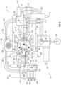
FIG. 2 is a cross-sectional side view of an illustrative example of a completion system arrangement that does not fall within the scope of the present invention; -
FIG. 3 is a cross-sectional side view of an illustrative, example of a completion system arrangement that does not fall within the scope of the present invention, where the structure is circumferentially disposed about the spool; -
FIG. 4 is a top view of the completion system arrangement shown inFIG. 3 ; -
FIG. 5 is a cross-sectional side view of an alternative example of the completion system that does not fall within the scope of the present invention; -
FIG. 6 is a cross-sectional side view of a completion system according to the present invention; and -
FIG. 7 is a cross-sectional side view of another example of a completion system that does not fall within the scope of the present invention. - Examples and the present invention will be described below. These described embodiments are only exemplary of the present invention. All features of an actual implementation may not be described in the specification. It should be appreciated that in the development of any such actual implementation, as in any engineering or design project, numerous implementation-specific decisions must be made to achieve the developers' specific goals, such as compliance with system-related and business-related constraints, which may vary from one implementation to another. Moreover, it should be appreciated that such a development effort might be complex, but would nevertheless be a routine undertaking of design, fabrication, and manufacture for those of ordinary skill having the benefit of this disclosure.
- When introducing elements of various embodiments of the present invention, the articles "a," "an," "the," and "said" are intended to mean that there are one or more of the elements. The terms "comprising," "including," and "having" are intended to be inclusive and mean that there may be additional elements other than the listed elements. Moreover, the use of "top," "bottom," "above," "below," and variations of these terms is made for convenience, but does not require any particular orientation of the components.
- Various arrangements of production control valves may be coupled to a wellhead in an assembly generally known as a tree, such as a vertical tree or a horizontal tree. With a vertical tree, after the tubing hanger and production tubing are installed in the high pressure wellhead housing or a spool such as a tubing spool, a blowout prevent (BOP) may be removed and the vertical tree may be locked and sealed onto the wellhead. The vertical tree includes one or more production passages containing actuated valves that extend vertically to respective lateral production fluid outlets in the vertical tree. The production passages and production valves are thus in-line with the production tubing.
- With a vertical tree, the tree may be removed while leaving the completion (e.g., the production tubing and hanger) in place. However, to pull the completion, the vertical tree must be removed and replaced with a BOP, which involves setting and testing plugs or relying on down-hole valves, which may be unreliable due to lack of use and/or testing. Moreover, removal and installation of the tree and BOP assembly generally requires robust lifting equipment, such as a rig, that may have high daily rental rates, for instance. The well is also in a vulnerable condition while the vertical tree and BOP are being exchanged and neither of these pressure-control devices is in position.
- Alternatively, trees with the arrangement of production control valves offset from the production tubing, generally called horizontal trees or spool trees, may be utilized. A spool tree also locks and seals onto the wellhead housing. However, the tubing hanger, instead of being located in the wellhead, locks and seals in the tree passage. After the tree is installed, the tubing string and tubing hanger are run into the tree using a tubing hanger running tool. A production passage extends through the tubing hanger, and seals to prevent fluid leakage, thereby facilitating a flow of production fluid into a corresponding production passage in the tree. A locking mechanism above the production seals locks the tubing hanger in place in the tree. With the production valves offset from the production tubing, the production tubing hanger and production tubing may be removed from the tree without having to remove the spool tree from the wellhead housing. Unfortunately, if the tree needs to be removed, the entire completion must also be removed, which takes considerable time and also involves setting and testing plugs or relying on down-hole valves, which may be unreliable due to lack of use and/or testing. Additionally, because the locking mechanism on the tubing hanger is above and blocks access to the production port seals, the entire completion must be pulled to service the seals.
- To manage expected maintenance costs, which are especially high for an offshore well, an operator may select equipment best suited for the expected type of maintenance. For example, a well operator may predict whether there will be a greater need in the future to pull the tree from the well for repair, or pull the completion, either for repair or for additional work in the well. Depending on the predicted maintenance events, an operator will decide whether the horizontal or vertical tree, each with its own advantages and disadvantages, is best suited for the expected conditions. For instance, with a vertical tree, it is more efficient to pull the tree and leave the completion in place. However, if the completion needs to be pulled, the tree must be pulled as well, increasing the time and expense of pulling the completion. Conversely, with a spool tree, it is more efficient to pull the completion, leaving the tree in place. However, if the tree needs to be pulled, the entire completion must be pulled as well, increasing the time and expense of pulling the tree. The life of the well could easily span 20 years and it is difficult to predict at the outset which capabilities are more desirable for maintenance over the life of the well. Thus, an incorrect prediction may significantly increase the cost of production over the life of the well. Further, jurisdiction regulations and other industry practices require the plugs on subsea equipment to include dual seal barriers between fluids in the well and open water environments, a so-called dual barrier requirement. With the production control equipment located at the surface, another system for accomplishing dual barrier protection is needed.
-
FIG. 1 is a block diagram that illustrates an exemplarywell completion system 10 that does not fall within the scope of the present invention. The illustratedwell completion system 10 can be configured to extract various minerals and natural resources, including hydrocarbons (e.g., oil and/or natural gas), or configured to inject substances into the earth. In some examples, thewell completion system 10 is land-based (e.g., a surface system) or subsea (e.g., a subsea system). As illustrated, thesystem 10 is a subsea system that includes awellhead 12 coupled to amineral deposit 14 via awell 16, wherein the well 16 includes awellhead hub 18, which can be a high pressure wellhead housing and awell bore 20. Thewellhead hub 18 generally includes a large diameter hub that is disposed at the termination of the well bore 20. Thewellhead hub 18 provides for the connection of thewellhead 12 to thewell 16. Although described as a subsea system, it should be appreciated that thewell completion system 10 may also be used as surface system. - The
wellhead 12 typically includes multiple components that control and regulate activities and conditions associated with the well 16. For example, thewellhead 12 generally includes bodies, valves, and seals that route produced minerals from themineral deposit 14, provide for regulating pressure in the well 16, and provide for the injection of chemicals into the well bore 20 (downhole). In the illustrated example, thewellhead 12 includes asubsea tree 22, a spool 24 (e.g., a tubing spool), and atubing hanger 26. Thesystem 10 may include other devices that are coupled to thewellhead 12, and devices that are used to assemble and control various components of thewellhead 12. For example, in the illustrated example, thesystem 10 includes a tubing hanger running tool (THRT) 28 suspended from a drill string 30. In certain examples, theTHRT 28 is lowered (e.g., run) from an offshore vessel to the well 16 and/or thewellhead 12. A blowout preventer (BOP) 32 may also be included, and may include a variety of valves, fittings and controls to block oil, gas, or other fluid from exiting the well in the event of an unintentional release of pressure or an overpressure condition. - As illustrated, the
spool 24 is coupled to thewellhead hub 18. Typically, thespool 24 is one of many components in a modular subsea orsurface completion system 10 that is run from an offshore vessel or surface system. Thespool 24 includes alongitudinal passage 34 configured to support thetubing hanger 26. In addition, thepassage 34 may provide access to the well bore 20 for various completion and workover procedures. For example, components can be run down to thewellhead 12 and disposed in thespool passage 34 to seal-off the well bore 20, to inject chemicals down-hole, to suspend tools down-hole, to retrieve tools down-hole, and the like. - As will be appreciated, the well bore 20 may contain elevated pressures. For example, the well bore 20 may include pressures that exceed 70 MPa (10,000 pounds per square inch (PSI)), that exceed 103 MPa (15,000 PSI), and/or that even exceed 140 MPa (20,000 PSI). Accordingly, well
completion systems 10 employ various mechanisms, such as mandrels, seals, plugs and valves, to control and regulate the well 16. For example, the illustratedtubing hanger 26 is typically disposed within thewellhead 12 to secure tubing suspended in the well bore 20, and to provide a path for hydraulic control fluid, chemical injections, and the like. Thehanger 26 includes alongitudinal bore 36 that extends through the center of thehanger 26, and that is in fluid communication with the well bore 20. As illustrated in the example ofFIG. 2 , thehanger 26 also includes alateral flow passage 38 in fluid communication with thelongitudinal passage 36. Thelateral flow passage 38 of thetubing hanger 26 is configured to transfer product (e.g., oil, natural gas, etc.) from the longitudinaltubing hanger passage 36 to alateral flow passage 40 of thespool 24. In the present example, thelateral flow passage 40 of thespool 24 extends from thelongitudinal spool passage 34 to ahub connection 42. Thehub connection 42 is configured to interface with amating hub connection 44 of thesubsea tree 22, thereby establishing a flow path from thelongitudinal passage 36 of thetubing hanger 26 through thelateral flow passages subsea tree 22. While the interface between thehub connection 42 and themating hub connection 44 is oriented along a plane substantially parallel to thelongitudinal passage 34 of thespool 24, it should be appreciated that alternative examples may employ an interface along a plane substantially perpendicular to thelongitudinal passage 34. -
FIG. 2 is a cross-sectional side view of an example of aspool 24 andsubsea tree 22 that does not fall within the scope of the present invention and that may be used in thecompletion system 10. As previously discussed, thespool 24 is configured to be positioned between thewellhead hub 18 and theBOP 32. Consequently, thespool 24 includes afirst end 46 configured to interface with thewellhead hub 18, and asecond end 48 configured to interface with theBOP 32. Thelongitudinal passage 34 extends in anaxial direction 45 between thefirst end 46 and thesecond end 48, thereby establishing a flow path through thespool 24. In the present example, acollet connector 50 serves to secure thefirst end 46 of thespool 24 to thewellhead hub 18. In addition, a cap 52 (e.g., an internal tree cap) is disposed within thelongitudinal passage 34 between thetubing hanger 26 and thesecond end 48 to block fluid flow into and out of thespool 24. As illustrated, thecap 52 includes afluid barrier 54, such as a wireline plug, and aseal 56, such as a rubber o-ring, for example. More than onefluid barrier 54 may also be used. As will be appreciated, thecap 52 may include a locking mechanism configured to secure thecap 52 to thelongitudinal passage 34 of thespool 24. Consequently, thecap 52 may be retrieved by releasing the locking mechanism, and then extracting thecap 52 from thepassage 34. In addition, the plug may be removable (e.g., via a wireline) to provide fluid communication with thelongitudinal passage 34. In addition, thefluid barrier 54 may be an adjustable barrier, such as an actuatable valve. The valve may be any suitable valve, such as by non-limiting example, a ball valve, a sliding sleeve valve, a shuttle valve, or a gate valve. The adjustable barrier(s) can thus open and close a longitudinal passage running through thecap 52 to allow mechanical and circulation access through the cap during workover operations, without having to pull plugs in thecap 52. - More than one
fluid barrier 54 may also be used in thecap 52 and thefluid barriers 54 may be different types, such as one plug and one valve. - As previously discussed, the
tubing hanger 26 is configured to support atubing string 57 that extends down the well bore 20 to themineral deposit 14. As will be appreciated, anannulus 58 of thespool 24 surrounds thetubing string 57 and may be filled with completion fluid. Afluid barrier 60, such as a plug or an adjustable barrier, is disposed within thelongitudinal passage 36 of thetubing hanger 26 and serves as a barrier between the product extracted from themineral deposit 14 and the completion fluid within theannulus 58. Thetubing hanger 26 may also include a profile for installing afluid barrier 60 in the hangerlongitudinal passage 36. Thus, afluid barrier 60 such as a plug or an actuatable
valve may be interchangeable in the profile. More than onebarrier 60 may also be used. Consequently, thebarrier 60 may block the flow of fluid up through the top of thetubing hanger 26. Thebarrier 60 may be an adjustable barrier such as an actuatable valve. The valve may be any suitable valve, such as by non-limiting example, a ball valve, a sliding sleeve valve, a shuttle valve, or a gate valve. The valve may be actuated electrically, hydraulically, mechanically, or by any other suitable means. More than onebarrier 60 may also be used. The valve can thus open and close thelongitudinal passage 36 of thetubing hanger 26 to allow direct downhole mechanical and circulation access during workover operations, without having to pull crown plugs in thetubing hanger 26. - At least one of the
barriers barrier barriers - In addition, the
tubing hanger 26 includes a seal 62 (e.g., rubber o-ring) disposed against thelongitudinal passage 34 of thespool 24 and configured to block fluid flow around thetubing hanger 26. The illustrated wellhead configuration also includes anisolation sleeve 64 disposed within thepassage 34 and extending from thefirst end 46 of thespool 24 to thewellhead hub 18. As illustrated, theisolation sleeve 64 includes a first seal 66 (e.g., rubber o-ring) in contact with the passage of thewellhead hub 18, and a second seal 68 (e.g., rubber o-ring) in contact with thepassage 34 of thespool 24. In this configuration, theisolation sleeve 64 may facilitate pressure testing of the seal between thewellhead hub 18 and thespool 24. Theisolation sleeve 64 may also serve as an additional barrier to block a flow of completion fluid from exiting thewellhead 12 through the interface between thespool 24 and thewellhead hub 18. - Furthermore, the
tubing hanger 26 includes afirst seal 70 positioned adjacent to thepassage 34 of thespool 24 and located in adownward direction 71 from thelateral flow passage 38. Thetubing hanger 26 also includes asecond seal 72 positioned adjacent to thepassage 34 and located in anupward direction 73 from thelateral flow passage 38. In the present example, theseals lateral flow passage 38, and to block flow of product (e.g., oil and/or natural gas) into theannulus 58. Consequently, a flow path will be established between thetubing string 57 and thelateral flow passage 40 of thespool 24, thereby facilitating the flow of product to thesubsea tree 22. Specifically, product will flow from thetubing string 57 in theupward direction 73 into thelongitudinal passage 36 of thetubing hanger 26. Because theactuatable valve 60 blocks the flow of product from exiting the top of thetubing hanger 26, the product will be directed through thelateral flow passage 38 of thetubing hanger 26 and into thelateral flow passage 40 of thespool 24. The product will then flow into thesubsea tree 22 via the interface between thehub connection 42 and themating hub connection 44. While theactuatable valve 60 serves to block the flow of product out of the top of thetubing hanger 26, it should be appreciated that theplug 54 within thecap 52 serves as a backup seal to block product from exiting thespool 24, thereby providing a dual barrier between the product and the environment. - In the present example, the
spool 24 includes one ormore valves 74, such as production valves, coupled to thelateral flow passage 40. As shown, the spool includes bothproduction valves 74 but it should also be appreciated that only oneproduction valve 74 may be included. It should also be appreciated that the term "production" as used to describevalve 74 is for convenience and that thevalve 74 may be used to regulate flow in either direction and for injection as well as production. Theproduction valves 74 are configured to control the flow of product between thespool 24 and thetree 22. For example, one or both of theproduction valves 74 may be closed prior to retrieving thetree 22, thereby blocking the flow of product from entering the environment. Conversely, once thetree 22 has between run or lowered into position, thevalves 74 may be opened to facilitate product flow to thesubsea tree 22. When twoproduction valves 74 are used and both in respective closed positions, two barriers are provided between the product flow and the environment, even when thetree 22 is removed. While the present example includesvalves 74, it should be appreciated that alternative examples may employ any suitable device (e.g., wireline plug) configured to substantially block production flow from the well 16 to thehub connection 42. As illustrated, with thehub connection 42 coupled to themating hub connection 44, thelateral flow passage 40 of thespool 24 is in fluid communication with aproduct flow passage 75 of thesubsea tree 22. In the present example, thehub connection 42 is coupled to themating hub connection 44 with aclamp 77, such as a manual clamp or a hydraulic connector. - In the present example, the
product flow passage 75 includes afirst valve 76 and asecond valve 78. As illustrated inFIG. 2 , thefirst valve 76 is positioned upstream of anannulus crossover valve 80, and thesecond valve 78 is positioned downstream from theannulus crossover valve 80.Valves valves annulus 58 andtubing string 57. In addition, theproduct flow passage 75 includes achoke 82 positioned downstream from thevalves flow passage 75. Theflow passage 75 also includes aflowline isolation valve 84 configured to selectively block fluid flow between thetree 22 and the surface. As illustrated, theproduct flow passage 75 terminates at aflowline hub 86 configured to interface with a conduit or manifold that conveys the product from thewellhead 12 to a surface vessel or platform. - Because the
tubing hanger 26 is substantially sealed to thepassage 34 of thespool 24 via theseals annulus 58 is blocked. Consequently, thespool 24 includes an upperannulus flow passage 88 and a lowerannulus flow passage 90 to regulate completion fluid pressure within anupper region 89 above thetubing hanger 26 and alower region 91 below thetubing hanger 26, respectively. Specifically, the upperannulus flow passage 88 extends from theupper region 89 to alateral flow passage 92, and the lowerannulus flow passage 90 extends from thelateral flow passage 92 to thelower region 91. In this configuration, completion fluid may be supplied and/or removed from eachregion annulus 58. In the present example, the upperannulus flow passage 88 includes anupper annulus valve 94, and the lowerannulus flow passage 90 includes alower annulus valve 96. Thevalves upper region 89 andlower region 91, respectively. - As illustrated, the lateral
annulus flow passage 92 extends through thehub connection 42 and interfaces with anannulus flow passage 97 of thesubsea tree 22, thereby establishing a completion fluid flow path between thespool 24 and thesubsea tree 22. In the present example, theannulus flow passage 97 includes anannulus valve 98 positioned upstream of theannulus crossover valve 80, and anannulus monitor valve 100 positioned downstream from theannulus crossover valve 80. As will be appreciated, theannulus valves valves annulus crossover valve 80 to adjust fluid flow to and from theannulus 58 and thetubing string 57. For example, if theannulus valve 98, theannulus monitor valve 100, thefirst valve 76, and thesecond valve 78 are in the open position, and theannulus crossover valve 80 is in the closed position, then a fluid connection will be established between theflowline hub 86 and thetubing string 57, and between anannulus junction 101 and theannulus 58. - In the present example, the
tubing hanger 26 includes avalve 63, or other closure element below thelateral flow passage 38. Thevalve 63 is configured to selectively block product flow to thesubsea tree 22 and may be operated hydraulically or otherwise. Thevalve 63 may also be included in a sub or other extension below thetubing hanger 26. Thevalve 63 works together with thebarrier 60 but also with the valve 102 (discussed below) to provide an environmental barrier to fluid flow, such as production fluid flow, when either thesubsea tree 22 or thecap 52 are not installed. - In the present example, the
tubing string 57 includes adownhole valve 102, such as for example a surface-controlled subsurface safety valve (SCSSV) 102 configured to selectively block product flow to thesubsea tree 22. For example, as an SCSSV, thevalve 102 may be hydrauhcally operated and biased toward a closed position (i.e., failsafe closed) to ensure that the SCSSV closes if the system experiences a reduction in hydraulic pressure. With at least two of thedownhole valve 102, thevalve 63, and at least one or both of thevalves 74 in respective closed positions, two barriers are provided between the fluid flow and the environment, even when thetree 22 is removed. In the present example, theSCSSV 102 is hydrauhcally controlled via aconduit 104 extending from thehub connection 42 to theSCSSV 102. As illustrated, theconduit 104 connects with aconduit 110 within thesubsea tree 22 when thehub connection 42 is mounted to themating hub connection 44, , thereby establishing a fluid connection between theconduit 104 within thespool 24 and theconduit 110 within thesubsea tree 22. The connection may be any type of sealing connection, such as a stab connection. The connection may also be configured to substantially block fluid flow into and out of therespective conduits conduit 110 is coupled to avalve 112 configured to selectively block hydraulic fluid flow to thedownhole valve 102. - The
spool 24 also includes a vent/test conduit 114 configured to regulate fluid flow to certain regions of thetubing hanger 26. As illustrated, theconduit 114 connects with aconduit 120 within thesubsea tree 22 when thehub connection 42 is mounted to themating hub connection 44, thereby establishing a fluid connection between theconduit 114 within thespool 24 and theconduit 120 within thesubsea tree 22. The connection may be any type of sealing connection, such as a stab connection. The connection may also be configured to substantially block fluid flow into and out of therespective conduits conduit 120 is coupled to avalve 122 configured to selectively block fluid flow to the vent/test conduit 114. - In the present example, the
spool 24 also includes achemical injection conduit 124 configured to inject chemicals, such as methanol, polymers, surfactants, etc., into the well bore 20 to improve recovery. As illustrated, theconduit 124 connects with aconduit 130 within thesubsea tree 22 when thehub connection 42 is mounted to themating hub connection 44, thereby establishing a fluid connection between theconduit 124 within thespool 24 and theconduit 130 within thesubsea tree 22. The connection may be any type of sealing connection, such as a stab connection. The connection may also be configured to substantially block fluid flow into and out of therespective conduits conduit 130 is coupled to avalve 132 configured to selectively block the flow of chemicals into the well bore 20. - In the present example, the
spool 24 also includes anotherhydraulic conduit 134 configured to operate a sliding sleeve within thetubing string 57. For example, thetubing string 57 may terminate in a first region of themineral deposit 14 and the sliding sleeve may be aligned with a second region of themineral deposit 14. In this configuration, when the sliding sleeve is in a closed position, thetubing string 57 may extract product from the first region. Conversely, when the sliding sleeve is in an open position, thetubing string 57 may extract product
from the second region. Consequently, product may be selectively extracted from various regions of themineral deposit 14 with asingle tubing string 57. As illustrated, theconduit 134 connects with aconduit 140 within thesubsea tree 22 when thehub connection 42 is mounted to themating hub connection 44, thereby establishing a fluid connection between theconduit 134 within thespool 24 and theconduit 140 within thesubsea tree 22. The connection may be any type of sealing connection, such as a stab connection. The connection may also be configured to substantially block fluid flow into and out of therespective conduits conduit 140 is coupled to avalve 142 configured to selectively block hydraulic fluid flow to the sliding sleeve. - While the present example includes four
conduits subsea tree 22 to thespool 24, it should be appreciated that alternative examples may include more or fewer conduits. For example, certain examples may include additional valves controlled by additional hydraulic conduits, additional sliding sleeves controlled by additional conduits and/or additional chemical injection conduits. - If valve maintenance is desired, the
tree 22 may be pulled by a ship, thereby substantially reducing maintenance costs compared to spool tree configurations in which a rig is employed to retrieve the spool tree. - Similarly, the
tubing hanger 26 may be retrieved without removing thesubsea tree 22. For example, to remove thetubing hanger 26, the well bore 20 may be plugged to block the flow of product into the environment. Next, thecap 52 may be removed to provide access to thetubing hanger 26. Finally, thetubing hanger 26 and attachedtubing string 57 may be retrieved via a rig, for example. Because thesubsea tree 22 does not block access to thelongitudinal passage 34 of thespool 24, thetree 22 may remain attached to thespool 24 during the tubing hanger retrieval process. Consequently, maintenance costs may be significantly
reduced compared to vertical tree configurations in which the vertical tree is removed prior to accessing thetubing hanger 26. - It should be appreciated that the example shown in
FIG. 2 may be used a subsea or surface system. -
FIG. 3 is a cross-sectional side view of another example of thespool 24 andsubsea tree 22 that may be used in thecompletion system 10 ofFIG. 1 . In this, thesubsea tree 22 includes a structure that is circumferentially disposed about thespool 24, as compared to the examples described above, in which the subsea tree structure is positioned at one circumferential location radially outward from thespool 24. As discussed in detail below, the structure of thesubsea tree 22 may be substantially equally balanced in theradial direction 47, thereby facilitating the running and/or retrieval processes. In addition, because the valves may be positioned farther apart than the examples described above, a remote operated vehicle (ROV) may have enhanced access to valve actuators. While acap 52 is employed in this example with aplug 54, it should be appreciated that thetubing hanger 26 includes afluid barrier 60 above thelateral flow passage 38 creating a dual-barrier configuration. - In the present example, the
subsea tree 22 is separated into aproduction valve block 151 and anannulus valve block 152. As illustrated, both valve blocks 151 and 152 are disposed radially outward from thespool 24, with each valve block located at a different circumferential position. As mentioned above, production valve block is not meant to limit thevalve block 151 only to production, as it may also be used for injection. As discussed in detail below, theproduction valve block 151 is supported by a frame that circumferentially extends about thespool 24. In the present example, theproduction valve block 151 includes theproduction flow passage 75 and the SCSSVhydraulic conduit 110, while theannulus valve block 152 includes theannulus flow passage 97, the vent/test conduit 120, thechemical injection conduit 130, and the sliding sleevehydraulic conduit 140. However, it should be appreciated that theconduits production valve block 151 may contain each of theconduits annulus valve block 152 only includes theannulus flow passage 97. Alternatively, theannulus valve block 152 may contain each of theconduits production valve block 151 only includes theproduction flow passage 75. It should be appreciated that corresponding lines extending from thesubsea tree 22 to the surface may be connected to the appropriate valve block to establish a fluid connection with theconduits - As illustrated, the
production valve block 151 includes themating hub connection 44 configured to interface with thehub connection 42. In the present example, thehub connection 42 interfaces with themating hub connection 44 along aplane 149 substantially perpendicular to thelongitudinal passage 34 of thespool 24. However, it should be appreciated that thehub connection 42 may interface with themating hub connection 44 along a plane substantially parallel to thelongitudinal passage 34 in alternative examples. As illustrated, the interface between thehub connection 42 and themating hub connection 44 establishes fluid connections between thelateral flow passage 40 and theproduction flow passage 75, and between theSCSSV conduits - Similarly, the
annulus valve block 152 includes an annulus connector 154 configured to interface with anannulus hub 156 of thespool 24. In the present example, theannulus hub 156 interfaces with the annulus connector 154 along aplane 149 substantially perpendicular to thelongitudinal passage 34 of thespool 24. However, it should be appreciated that theannulus hub 156 may interface with the annulus connector 154 along a plane substantially parallel to thelongitudinal passage 34 in alternative examples. - As illustrated, the interface between the
annulus hub 156 and the annulus connector 154
establishes fluid connections between the annuluslateral flow passage 92 and theannulus flow passage 97 within thesubsea tree 22. In addition, connections are established between the vent/test conduits chemical injection conduits hydraulic conduits spool 24 is fluidly coupled to a corresponding conduit with thesubsea tree 22. - In another example, the
subsea tree 22 includes anannulus crossover loop 158 extending between theannulus valve block 152 and theproduction valve block 151. As illustrated, theannulus crossover loop 158 contains anannulus conduit 160 extending between theannulus flow passage 97 and theannulus crossover valve 80, thereby establishing a fluid connection between theannulus 58 and thetubing string 57. Thesubsea tree 22 also includes afluid flow loop 162 extending between theproduction valve block 151 and aproduction choke assembly 164. As illustrated, theproduction choke assembly 164 includes thechoke 82 and theflowline isolation valve 84. Theflow loop 162 contains theflow passage 75, thereby establishing a fluid connection between thevalve 78 and thechoke 82. Furthermore, theflowline connection hub 86 is coupled to thechoke assembly 164 to facilitate fluid flow between thesubsea tree 22 and the surface. Because the components of thesubsea tree 22 are circumferentially distributed about thespool 24, thetree 22 may be substantially balanced, thereby facilitating running and retrieving operations. However, in this example, acap 52 includes afluid barrier 54, and it should be appreciated that thetubing hanger 26 also includes afluid barrier 60 to create the dual-barrier configuration. -
FIG. 4 is a top view of thespool 24 andsubsea tree 22 shown inFIG. 3 . As previously discussed, thesubsea tree 22 includes aframe 166 circumferentially disposed about thespool 24 and configured to support theproduction valve block 151. As illustrated, theframe 166 also supports thechoke assembly 164 and an
electronic control pod 168. In contrast, theannulus valve block 152 is supported by the annulus cross overloop 158 and the annulus connector 154. However, because the presentannulus valve block 152 only includes a limited number of valves, the weight of thevalve block 152 may not induce significant stress within theloop 158 or the connector 154. Because the structure of thesubsea tree 22 is circumferentially disposed about thespool 24, thesubsea tree 22 may be substantially balanced, thereby facilitating running and retrieving operations. - In addition, because the valves are located in various circumferential positions within the
subsea tree 22, an ROV may have enhanced access to valve actuators. For example, in the present example, theproduction valve block 151 includes aproduction valve actuator 170 configured to control theproduction valve 78, an annuluscrossover valve actuator 172 configured to control theannulus crossover valve 80, and anSCSSV valve actuator 174 configured to control theSCSSV valve 112. In addition, thechoke assembly 164 includes a flowlineisolation valve actuator 176 configured to control theflowline isolation valve 84. Furthermore, theannulus valve block 152 includes anannulus valve actuator 178 configured to control theannulus valve 98, an annulusmonitor valve actuator 179 configured to control theannulus monitor valve 100, a vent/test valve actuator 180 configured to control the vent/test valve 122, a chemical injection valve actuator 182 configured to control thechemical injection valve 132, and a slidingsleeve valve actuator 184 configured to control the slidingsleeve valve 142. By circumferentially distributing the actuators about thetree 22, the ROV may readily access each actuator. In addition, thespool 24 includes valve actuators configured to control the valves within thespool 24. Specifically, thespool 24 includes aproduction valve actuator 186 configured to control theproduction valve 74, an upperannulus valve actuator 188 configured to control theupper annulus valve 94, and a lowerannulus valve actuator 190 configured to control thelower annulus valve 96. - It should be appreciated that the examples shown in
FIGS. 3 and4 may be used a subsea or surface system. - In
FIG. 5 , another example is presented includingfluid barriers 54 in thecap 52 andfluid barriers 60 in thetubing hanger 26, similar to the example shown inFIG. 2 . It should be appreciated that the following discussion regarding fluid barriers may also be used in an example similar to the example shown inFIGS. 3 and4 . As with previous examples, thetubing hanger 26 may also include a profile for installing afluid barrier 60 in the hangerlongitudinal passage 36. Thus, afluid barrier 60 such as a plug or an actuatable valve may be interchangeable in the profile. In the example shown inFIG. 5 , more than onebarrier 54 is shown in thecap 52 and more than onebarrier 60 is shown in thetubing hanger 26. Although thebarriers 60 are both shown above thelateral flow passage 38 in thetubing hanger 26, it should be appreciated that one or both of the barriers may also be located below thelateral flow passage 38. As mentioned in the discussion above with respect toFIG. 2 , more than one of thebarriers barriers barriers barriers tubing hanger 26 includes twobarriers 60, then thecap 52 is not necessary and need not be used. - The adjustable barrier may include a valve (or valves) that serve as the fluid barrier that can open and close the passage in the
cap 52 and or thelongitudinal passage 36 in thetubing hanger 26 to allow direct downhole access during a subsea workover operation. In at least some configurations, this can be done without having to pull plugs when the tubing hanger passage is open, thus allowing passage to the production tubing. - An example of the utility of using an adjustable barrier is that an alternate downhole fluid path for well circulation can be achieved by opening the valve(s) 54 in the cap longitudinal passage. With the valve(s) open, fluid may be pumped down through the
cap 52 to above thetubing hanger 26 and into an opened annulus crossover circulation loop in the tree. The annulus crossover circulation loop connects to the production master valve passage run extending through the tree and hanger and then connecting to the tubing hanger vertical passage just below a tubing hanger barrier and therefore down into the production tubing. Alternatively or additionally, fluid may flow through thebarriers 54 as communicated with theproduction tubing annulus 58 through the upperannulus flow passage 88 and a lowerannulus flow passage 90 in thespool 24. - In this or other examples, having a valve that can open and close the longitudinal passage in the tubing hanger passage will allow direct down hole mechanical and circulation access during a subsea workover operation, without having to pull plugs. In this configuration, the master valve located in the tubing head spool could be now located in the upper tree section.
- It should be appreciated that the example shown in
FIG. 5 may be used a subsea or surface system. - In
FIG. 6 , according to the present invention, incorporating an annulus access valve(s) 55 located in an annulus access passage in thecap 52 separate from and adjacent to the longitudinal passage will also allow well circulation. This is achieved by pumping fluid through the choke and kill lines located below closed rams and through the riser down to the cap. The valve(s) 55 in thecap 52 is then opened allowing the fluid (or gas) to circulate below thecap 52 as discussed above. - An alternate or additional arrangement further incorporates an annulus access valve(s) 61 in annulus access passage 65 not located in the tubing hanger
longitudinal passage 36 but adjacent to it will also allow annulus access from
above thetubing hanger 26 to below thetubing hanger 26. When used with or without thecap barriers 54 or annulus access valve(s) 55, fluid may circulate between above thecap 52 and theproduction tubing annulus 58 going through thetubing hanger 26 itself. This would eliminate the need for an annulus route typically located in the tree or spool body which by-passes thetubing hanger 26. - It should be appreciated that the invention shown in
FIG. 6 may be used as a subsea or surface system. - In
FIG. 7 , another example is presented includingfluid barriers 60 in thetubing hanger 26, similar to the example shown inFIG. 5 . It should be appreciated that the following discussion regarding fluid barriers may also be used in the invention shown inFIG 6 and the example shown inFIG.5 . As with previous examples, thetubing hanger 26 may also include a profile for installing afluid barrier 60 in the hangerlongitudinal passage 36. Thus, afluid barrier 60 such as a plug or an actuatable valve may be interchangeable in the profile. In the example shown inFIG. 7 , thetubing hanger 24 is landed in thespool 24 and a subseavertical tree 22 is connected with thespool 24. The verticalsubsea tree 22 is in fluid communication with the tubing hangerlongitudinal passage 36 to transfer the fluid between thespool 24 to the verticalsubsea tree 22. Thespool 24 may either be a tubing head spool or a high pressure wellhead housing. - More than one
barrier 60 is shown in thelongitudinal passage 36 of thetubing hanger 26. As mentioned in the discussion above with respect toFIG. 5 , more than one of thebarriers 60 may be an adjustable fluid barrier, such as an actuatable valve. Additionally, at least one of thebarriers 60 is an adjustable barrier. If not an adjustable barrier, the remainingbarriers 60 are non-adjustable barriers, such as removable plugs. Any combination of barriers where at least one of the barriers is adjustable may be used. For example, all of thebarriers 60 may be adjustable barriers. - The adjustable barrier may include a valve (or valves) that serve as the fluid barrier that can open and close the passage in the
longitudinal passage 36 in thetubing hanger 26 to allow direct downhole access during a subsea workover operation. In at least some configurations, this can be done without having to pull plugs when the tubing hanger passage is open, thus allowing passage to the production tubing. - In the example shown in
FIG. 7 , thetubing hanger 26 includes afluid barrier 63, such as an actuatable valve or other closure element below thetubing hanger 26. Thevalve 63 is configured to selectively block product flow to thesubsea tree 22 and may be operated hydraulically or otherwise. Thevalve 63 may also be included in a sub or other extension below thetubing hanger 26. Thevalve 63 works together with the barrier(s) 60 but also with the valve 102 (not shown) to provide an environmental barrier to production fluid flow when thesubsea tree 22 is not installed. - Also shown in
FIG. 7 are optional annulus access valve(s) 61 in annulus access passage 65 not located in the tubing hangerlongitudinal passage 36 but adjacent to it will also allow annulus access from above thetubing hanger 26 to below thetubing hanger 26. Annulus access valve(s) 61 would eliminate the need for an annulus route typically located in the tree or spool body which by-passes thetubing hanger 26. Although not shown, thespool 24 may also include an upper annulus flow passage and a lower annulus flow passage as discussed above to regulate pressure within anupper region 89 above thetubing hanger 26 and alower region 91 below thetubing hanger 26, respectively. - An example of the utility of using an adjustable barrier is that an alternate downhole fluid path for well circulation can be achieved by opening the
adjustable barriers tubing hanger 26. With the valve(s) open, fluid may flow through the hangerlongitudinal passage 36 and the annulus access passage 65 to circulate fluid in the well. In this or other examples, having a
valve that can open and close the production passage in the tubing hanger passage will allow direct down hole mechanical and circulation access during a subsea workover operation, without having to pull plugs. - It should be appreciated that the example shown in
FIG. 7 may be used a subsea or surface system. - In all of the examples described above and shown in
FIGS. 1 to 5 and7 and in the present invention described and shown inFIG. 6 , accessing either or both of the tubing hangerlongitudinal passage 36 and the cap longitudinal passage could save the operator time and money as opposed to the required steps necessary to pull plugs to gain access. In addition, the examples/embodiments eliminate any potential issues previously seen involving the removal of stuck plugs or the re-establishment of new plugs in a damaged or debris filled passage. Additionally, all of the examples shown inFIGS. 1-5 and7 and the present invention shown inFIG. 6 may be used in a subsea or surface system. - The invention is to cover all modifications, equivalents, and alternatives falling within the scope of the invention as defined by the following appended claims.
Claims (11)
- A system for accessing a well, comprising:a spool (24) comprising a longitudinal passage (34) and a longitudinal upper end (48), the spool (24) further comprising a spool hubconnection (42) and a spool lateral flow passage (40) extending through the spool fromthe spool longitudinal passage (34) to the spool hub connection (42), said spool hub connection (42) being configured to interface with a mating hub connection (44) of a horizontal tree (22), said spool hub connection (42) being configured to establish a flow path from the spool lateral flow passage (40) and into the horizontal tree (22) when the spool hub connection (42) being is coupled with the mating hub connection (44);a tubing hanger (26) installed and supported in the spool longitudinal passage (34) and comprising a hanger longitudinal passage (36) through the tubing hanger (26), the tubing hanger (26) including a lateral flow passage (38) extending through the tubing hanger and in fluid communication with the hanger longitudinal passage (36), the hanger lateral flow passage (38) being configured to transfer a product from the hanger longitudinal passage (36) to the spool lateral passage (40), an upper end of the hanger longitudinal passage (36) being in fluid communication with the spool longitudinal passage (34);fluid barriers (60) within the hanger longitudinal passage (36) to control access to the well, at least one of the fluid barriers (60) comprising an adjustable barrier, wherein the adjustable barrier comprises an actuatable valve;a cap (52) configured to be disposed in the spool longitudinal passage (34) between the tubing hanger (26) and the upper longitudinal end (48), the cap (52) comprising a cap longitudinal passage through the cap (52) , an upper end and a lower end of the cap longitudinal passage being in fluid communication with the spool longitudinal passage (34); andan adjustable barrier (54) located in the cap longitudinal passage to control access to the well, characterized in the cap (52) further comprising an actuatable valve (55) in an annulus access passage extending through the cap (52) along the cap longitudinal passage and separate from the cap longitudinal passage, an upper end and a lower end of the cap annulus access passage being in fluid communication with the spool longitudinal passage (34), wherein, when the actuatable valve (55) in the cap annulus passage is open, a fluid can be pumped from above the cap (52) and down through the cap (52) to above the tubing hanger (26) .
- The system of claim 1, further comprising more than one actuatable valve (60) in the hanger longitudinal passage (36) of the tubing hanger (26).
- The system of claim 1, wherein the adjustable barrier (54) in the cap longitudinal passage comprises an actuatable valve.
- The system of claim 3, further comprising more than one actuatable valve in the cap annulus access passage.
- The system of claim 1, further comprising an actuatable valve (61) in an annulus access passage extending through the tubing hanger (26) along the hanger longitudinal passage (36) and separate from the hanger longitudinal passage (36).
- The system of claim 1, further comprising a production tubing string (57) suspended from the tubing hanger (26), an inside of the production tubing string (57) being in fluid communication with the hanger longitudinal passage (36) and the production tubing string (57) comprising a downhole valve (102).
- The system of claim 1, further comprising:a production tubing string (57) suspended from the tubing hanger (26), an inside of the production tubing string (57) being in fluid communication with the hanger longitudinal passage (36); andthe spool (24) comprising an annulus flow passage (88, 90) open to and extending between an upper region above the tubing hanger (26) and a lower region below the tubing hanger (26) in fluid communication with an area surrounding the outside of the production tubing string (57).
- The system of claim 1, further comprising a valve (74) in the spool lateral flow passage (40).
- The system of claim 1, further comprising:a production tubing string (57) suspended from the tubing hanger (26), an inside of the production tubing string (57) being in fluid communication with the tubing hanger longitudinal passage (36); andan additional fluid barrier (60) in the tubing hanger longitudinal passage (36) below the tubing lateral flow passage (38) in fluid communication with the hanger longitudinal passage (36).
- The system of claim 1, wherein the spool (24) is part of a high pressure wellhead assembly (10).
- The system of claim 1, wherein the spool (24) is connected to a separate high pressure wellhead housing (18).
Applications Claiming Priority (2)
| Application Number | Priority Date | Filing Date | Title |
|---|---|---|---|
| US14/339,294 US10309190B2 (en) | 2014-07-23 | 2014-07-23 | System and method for accessing a well |
| PCT/EP2015/065635 WO2016012245A2 (en) | 2014-07-23 | 2015-07-08 | A system and method for accessing a well |
Publications (2)
| Publication Number | Publication Date |
|---|---|
| EP3172396A2 EP3172396A2 (en) | 2017-05-31 |
| EP3172396B1 true EP3172396B1 (en) | 2023-04-26 |
Family
ID=53540748
Family Applications (1)
| Application Number | Title | Priority Date | Filing Date |
|---|---|---|---|
| EP15736245.0A Active EP3172396B1 (en) | 2014-07-23 | 2015-07-08 | A system and method for accessing a well |
Country Status (4)
| Country | Link |
|---|---|
| US (1) | US10309190B2 (en) |
| EP (1) | EP3172396B1 (en) |
| BR (1) | BR112017000842A2 (en) |
| WO (1) | WO2016012245A2 (en) |
Families Citing this family (20)
| Publication number | Priority date | Publication date | Assignee | Title |
|---|---|---|---|---|
| US10309190B2 (en) * | 2014-07-23 | 2019-06-04 | Onesubsea Ip Uk Limited | System and method for accessing a well |
| US9909380B2 (en) | 2015-02-25 | 2018-03-06 | Onesubsea Ip Uk Limited | System and method for accessing a well |
| WO2019027448A1 (en) * | 2017-08-01 | 2019-02-07 | Fmc Technologies, Inc. | Large bore open water lubricator |
| US10900315B2 (en) * | 2019-03-04 | 2021-01-26 | Saudi Arabian Oil Company | Tubing hanger system |
| US12291939B2 (en) | 2019-10-29 | 2025-05-06 | Innovex International, Inc. | Electrical actuation of a valve in a wellhead assembly |
| NO20201162A1 (en) | 2019-10-29 | 2021-04-30 | Dril Quip Inc | Reduced stroke gate valve |
| US11371326B2 (en) | 2020-06-01 | 2022-06-28 | Saudi Arabian Oil Company | Downhole pump with switched reluctance motor |
| US11499563B2 (en) | 2020-08-24 | 2022-11-15 | Saudi Arabian Oil Company | Self-balancing thrust disk |
| US11920469B2 (en) | 2020-09-08 | 2024-03-05 | Saudi Arabian Oil Company | Determining fluid parameters |
| US11719065B2 (en) * | 2020-11-13 | 2023-08-08 | Onesubsea Ip Uk Limited | Configurable coupling assembly |
| US11644351B2 (en) | 2021-03-19 | 2023-05-09 | Saudi Arabian Oil Company | Multiphase flow and salinity meter with dual opposite handed helical resonators |
| US11591899B2 (en) | 2021-04-05 | 2023-02-28 | Saudi Arabian Oil Company | Wellbore density meter using a rotor and diffuser |
| US11913464B2 (en) | 2021-04-15 | 2024-02-27 | Saudi Arabian Oil Company | Lubricating an electric submersible pump |
| US11994016B2 (en) | 2021-12-09 | 2024-05-28 | Saudi Arabian Oil Company | Downhole phase separation in deviated wells |
| US12085687B2 (en) | 2022-01-10 | 2024-09-10 | Saudi Arabian Oil Company | Model-constrained multi-phase virtual flow metering and forecasting with machine learning |
| US12012824B2 (en) * | 2022-03-15 | 2024-06-18 | Baker Hughes Oilfield Operations Llc | Through-tubing electrical submersible pump for live wells and method of deployment |
| US12601237B2 (en) | 2022-04-26 | 2026-04-14 | Conocophillips Company | Temporary suspension of completed hydrocarbon wells |
| BR102023012935A2 (en) * | 2022-08-16 | 2024-03-12 | Dril-Quip, Inc. | ARRANGEMENT OF BARRIER IN WELL HEAD ASSEMBLY |
| US12163396B2 (en) * | 2022-10-21 | 2024-12-10 | Chevron U.S.A. Inc. | Systems and methods for independent control and operations of tubing and annulus at the wellhead |
| GB2627074A (en) * | 2023-01-31 | 2024-08-14 | Dril Quip Inc | A system including an electrical actuator for a valve in a wellhead assembly |
Citations (1)
| Publication number | Priority date | Publication date | Assignee | Title |
|---|---|---|---|---|
| WO2005071221A1 (en) * | 2004-01-23 | 2005-08-04 | Enovate Systems Limited | Completion suspension valve system |
Family Cites Families (25)
| Publication number | Priority date | Publication date | Assignee | Title |
|---|---|---|---|---|
| US4804045A (en) * | 1986-11-06 | 1989-02-14 | Reed Lehman T | Oil and gas well diversionary spool assembly |
| GB8801850D0 (en) | 1988-01-28 | 1988-02-24 | British Petroleum Co Plc | Tubing hanger shut-off mechanism |
| US5148865A (en) * | 1991-04-08 | 1992-09-22 | Reed Lehman T | Multi-conversion wellhead assembly |
| DE69226630T2 (en) * | 1992-06-01 | 1998-12-24 | Cooper Cameron Corp., Houston, Tex. | Wellhead |
| US5577556A (en) * | 1995-01-17 | 1996-11-26 | Reed; Lehman T. | Unitary diversionary-tubing hanger and energizable rod seal |
| GB2319795B (en) * | 1996-11-22 | 2001-01-10 | Vetco Gray Inc Abb | Insert tree |
| GB2320937B (en) * | 1996-12-02 | 2000-09-20 | Vetco Gray Inc Abb | Horizontal tree block for subsea wellhead |
| US6082460A (en) * | 1997-01-21 | 2000-07-04 | Cooper Cameron Corporation | Apparatus and method for controlling hydraulic control fluid circuitry for a tubing hanger |
| EP1021637B1 (en) | 1997-10-07 | 2004-02-11 | FMC Technologies, Inc. | Slimbore subsea completion system and method |
| AT408869B (en) | 1998-01-30 | 2002-03-25 | Tesma Motoren Getriebetechnik | CLOSURE LID |
| AU2453300A (en) * | 1999-02-11 | 2000-08-29 | Fmc Corporation | Subsea completion apparatus |
| CA2328666A1 (en) * | 2000-01-11 | 2001-07-11 | Cooper Cameron Corporation | Wellhead assembly |
| AU4778401A (en) * | 2000-03-24 | 2001-10-08 | Fmc Corp | Tubing head seal assembly |
| US6520263B2 (en) * | 2001-05-18 | 2003-02-18 | Cooper Cameron Corporation | Retaining apparatus for use in a wellhead assembly and method for using the same |
| WO2002097008A2 (en) * | 2001-05-25 | 2002-12-05 | Dril-Quip, Inc. | Horizontal spool tree assembly |
| US6729392B2 (en) | 2002-02-08 | 2004-05-04 | Dril-Quip, Inc. | Tubing hanger with ball valve in the annulus bore |
| US6966383B2 (en) * | 2002-12-12 | 2005-11-22 | Dril-Quip, Inc. | Horizontal spool tree with improved porting |
| GB2397312B (en) * | 2003-01-17 | 2005-07-27 | Fmc Technologies | Well completion system |
| US20040262010A1 (en) * | 2003-06-26 | 2004-12-30 | Milberger Lionel J. | Horizontal tree assembly |
| US7121346B2 (en) * | 2003-11-18 | 2006-10-17 | Cameron International Corporation | Intervention spool for subsea use |
| US7331396B2 (en) * | 2004-03-16 | 2008-02-19 | Dril-Quip, Inc. | Subsea production systems |
| NO333955B1 (en) | 2007-11-23 | 2013-10-28 | Fmc Kongsberg Subsea As | Underwater horizontal Christmas tree |
| US8794334B2 (en) * | 2010-08-25 | 2014-08-05 | Cameron International Corporation | Modular subsea completion |
| GB2510267B (en) * | 2011-08-23 | 2018-09-26 | Total Sa | A subsea wellhead assembly,a subsea installation using said wellhead assembly, and a method for completing a wellhead assembly |
| US10309190B2 (en) * | 2014-07-23 | 2019-06-04 | Onesubsea Ip Uk Limited | System and method for accessing a well |
-
2014
- 2014-07-23 US US14/339,294 patent/US10309190B2/en active Active
-
2015
- 2015-07-08 WO PCT/EP2015/065635 patent/WO2016012245A2/en not_active Ceased
- 2015-07-08 BR BR112017000842A patent/BR112017000842A2/en not_active Application Discontinuation
- 2015-07-08 EP EP15736245.0A patent/EP3172396B1/en active Active
Patent Citations (2)
| Publication number | Priority date | Publication date | Assignee | Title |
|---|---|---|---|---|
| WO2005071221A1 (en) * | 2004-01-23 | 2005-08-04 | Enovate Systems Limited | Completion suspension valve system |
| US20070204999A1 (en) * | 2004-01-23 | 2007-09-06 | Cleveland Clinic Foundation, The | Completion Suspension Valve System |
Also Published As
| Publication number | Publication date |
|---|---|
| WO2016012245A2 (en) | 2016-01-28 |
| WO2016012245A3 (en) | 2016-03-17 |
| US20160024878A1 (en) | 2016-01-28 |
| BR112017000842A2 (en) | 2017-12-05 |
| US10309190B2 (en) | 2019-06-04 |
| EP3172396A2 (en) | 2017-05-31 |
Similar Documents
| Publication | Publication Date | Title |
|---|---|---|
| US10309190B2 (en) | System and method for accessing a well | |
| US9631460B2 (en) | Modular subsea completion | |
| US9540894B2 (en) | Tubing hanger running tool with integrated landing features | |
| US9869147B2 (en) | Subsea completion with crossover passage | |
| US8662184B2 (en) | Multi-section tree completion system | |
| US8668004B2 (en) | Tubing hanger running tool with integrated pressure release valve | |
| US9976372B2 (en) | Universal frac sleeve | |
| US9534466B2 (en) | Cap system for subsea equipment | |
| US9051824B2 (en) | Multiple annulus universal monitoring and pressure relief assembly for subsea well completion systems and method of using same | |
| US20100252251A1 (en) | Safety device for retrieving component within wellhead | |
| GB2523695B (en) | Subsea completion with a tubing spool connection system | |
| EP3262275B1 (en) | System and method for accessing a well |
Legal Events
| Date | Code | Title | Description |
|---|---|---|---|
| STAA | Information on the status of an ep patent application or granted ep patent |
Free format text: STATUS: THE INTERNATIONAL PUBLICATION HAS BEEN MADE |
|
| PUAI | Public reference made under article 153(3) epc to a published international application that has entered the european phase |
Free format text: ORIGINAL CODE: 0009012 |
|
| STAA | Information on the status of an ep patent application or granted ep patent |
Free format text: STATUS: REQUEST FOR EXAMINATION WAS MADE |
|
| 17P | Request for examination filed |
Effective date: 20170111 |
|
| AK | Designated contracting states |
Kind code of ref document: A2 Designated state(s): AL AT BE BG CH CY CZ DE DK EE ES FI FR GB GR HR HU IE IS IT LI LT LU LV MC MK MT NL NO PL PT RO RS SE SI SK SM TR |
|
| AX | Request for extension of the european patent |
Extension state: BA ME |
|
| RIN1 | Information on inventor provided before grant (corrected) |
Inventor name: KOCUREK, CHRISTOPHER G. Inventor name: JUNE, DAVID R. Inventor name: BHAT, VENKATESH |
|
| DAV | Request for validation of the european patent (deleted) | ||
| DAX | Request for extension of the european patent (deleted) | ||
| STAA | Information on the status of an ep patent application or granted ep patent |
Free format text: STATUS: EXAMINATION IS IN PROGRESS |
|
| 17Q | First examination report despatched |
Effective date: 20180608 |
|
| GRAP | Despatch of communication of intention to grant a patent |
Free format text: ORIGINAL CODE: EPIDOSNIGR1 |
|
| STAA | Information on the status of an ep patent application or granted ep patent |
Free format text: STATUS: GRANT OF PATENT IS INTENDED |
|
| INTG | Intention to grant announced |
Effective date: 20211209 |
|
| GRAJ | Information related to disapproval of communication of intention to grant by the applicant or resumption of examination proceedings by the epo deleted |
Free format text: ORIGINAL CODE: EPIDOSDIGR1 |
|
| STAA | Information on the status of an ep patent application or granted ep patent |
Free format text: STATUS: EXAMINATION IS IN PROGRESS |
|
| INTC | Intention to grant announced (deleted) | ||
| GRAP | Despatch of communication of intention to grant a patent |
Free format text: ORIGINAL CODE: EPIDOSNIGR1 |
|
| STAA | Information on the status of an ep patent application or granted ep patent |
Free format text: STATUS: GRANT OF PATENT IS INTENDED |
|
| INTG | Intention to grant announced |
Effective date: 20220607 |
|
| GRAJ | Information related to disapproval of communication of intention to grant by the applicant or resumption of examination proceedings by the epo deleted |
Free format text: ORIGINAL CODE: EPIDOSDIGR1 |
|
| STAA | Information on the status of an ep patent application or granted ep patent |
Free format text: STATUS: EXAMINATION IS IN PROGRESS |
|
| INTC | Intention to grant announced (deleted) | ||
| GRAP | Despatch of communication of intention to grant a patent |
Free format text: ORIGINAL CODE: EPIDOSNIGR1 |
|
| STAA | Information on the status of an ep patent application or granted ep patent |
Free format text: STATUS: GRANT OF PATENT IS INTENDED |
|
| INTG | Intention to grant announced |
Effective date: 20221121 |
|
| GRAS | Grant fee paid |
Free format text: ORIGINAL CODE: EPIDOSNIGR3 |
|
| GRAA | (expected) grant |
Free format text: ORIGINAL CODE: 0009210 |
|
| STAA | Information on the status of an ep patent application or granted ep patent |
Free format text: STATUS: THE PATENT HAS BEEN GRANTED |
|
| AK | Designated contracting states |
Kind code of ref document: B1 Designated state(s): AL AT BE BG CH CY CZ DE DK EE ES FI FR GB GR HR HU IE IS IT LI LT LU LV MC MK MT NL NO PL PT RO RS SE SI SK SM TR |
|
| REG | Reference to a national code |
Ref country code: GB Ref legal event code: FG4D |
|
| REG | Reference to a national code |
Ref country code: CH Ref legal event code: EP |
|
| REG | Reference to a national code |
Ref country code: DE Ref legal event code: R096 Ref document number: 602015083310 Country of ref document: DE |
|
| REG | Reference to a national code |
Ref country code: AT Ref legal event code: REF Ref document number: 1562931 Country of ref document: AT Kind code of ref document: T Effective date: 20230515 |
|
| REG | Reference to a national code |
Ref country code: IE Ref legal event code: FG4D |
|
| REG | Reference to a national code |
Ref country code: LT Ref legal event code: MG9D |
|
| REG | Reference to a national code |
Ref country code: NL Ref legal event code: MP Effective date: 20230426 |
|
| REG | Reference to a national code |
Ref country code: AT Ref legal event code: MK05 Ref document number: 1562931 Country of ref document: AT Kind code of ref document: T Effective date: 20230426 |
|
| PG25 | Lapsed in a contracting state [announced via postgrant information from national office to epo] |
Ref country code: NL Free format text: LAPSE BECAUSE OF FAILURE TO SUBMIT A TRANSLATION OF THE DESCRIPTION OR TO PAY THE FEE WITHIN THE PRESCRIBED TIME-LIMIT Effective date: 20230426 |
|
| PG25 | Lapsed in a contracting state [announced via postgrant information from national office to epo] |
Ref country code: SE Free format text: LAPSE BECAUSE OF FAILURE TO SUBMIT A TRANSLATION OF THE DESCRIPTION OR TO PAY THE FEE WITHIN THE PRESCRIBED TIME-LIMIT Effective date: 20230426 Ref country code: PT Free format text: LAPSE BECAUSE OF FAILURE TO SUBMIT A TRANSLATION OF THE DESCRIPTION OR TO PAY THE FEE WITHIN THE PRESCRIBED TIME-LIMIT Effective date: 20230828 Ref country code: NO Free format text: LAPSE BECAUSE OF FAILURE TO SUBMIT A TRANSLATION OF THE DESCRIPTION OR TO PAY THE FEE WITHIN THE PRESCRIBED TIME-LIMIT Effective date: 20230726 Ref country code: ES Free format text: LAPSE BECAUSE OF FAILURE TO SUBMIT A TRANSLATION OF THE DESCRIPTION OR TO PAY THE FEE WITHIN THE PRESCRIBED TIME-LIMIT Effective date: 20230426 Ref country code: AT Free format text: LAPSE BECAUSE OF FAILURE TO SUBMIT A TRANSLATION OF THE DESCRIPTION OR TO PAY THE FEE WITHIN THE PRESCRIBED TIME-LIMIT Effective date: 20230426 |
|
| PG25 | Lapsed in a contracting state [announced via postgrant information from national office to epo] |
Ref country code: RS Free format text: LAPSE BECAUSE OF FAILURE TO SUBMIT A TRANSLATION OF THE DESCRIPTION OR TO PAY THE FEE WITHIN THE PRESCRIBED TIME-LIMIT Effective date: 20230426 Ref country code: PL Free format text: LAPSE BECAUSE OF FAILURE TO SUBMIT A TRANSLATION OF THE DESCRIPTION OR TO PAY THE FEE WITHIN THE PRESCRIBED TIME-LIMIT Effective date: 20230426 Ref country code: LV Free format text: LAPSE BECAUSE OF FAILURE TO SUBMIT A TRANSLATION OF THE DESCRIPTION OR TO PAY THE FEE WITHIN THE PRESCRIBED TIME-LIMIT Effective date: 20230426 Ref country code: LT Free format text: LAPSE BECAUSE OF FAILURE TO SUBMIT A TRANSLATION OF THE DESCRIPTION OR TO PAY THE FEE WITHIN THE PRESCRIBED TIME-LIMIT Effective date: 20230426 Ref country code: IS Free format text: LAPSE BECAUSE OF FAILURE TO SUBMIT A TRANSLATION OF THE DESCRIPTION OR TO PAY THE FEE WITHIN THE PRESCRIBED TIME-LIMIT Effective date: 20230826 Ref country code: HR Free format text: LAPSE BECAUSE OF FAILURE TO SUBMIT A TRANSLATION OF THE DESCRIPTION OR TO PAY THE FEE WITHIN THE PRESCRIBED TIME-LIMIT Effective date: 20230426 Ref country code: GR Free format text: LAPSE BECAUSE OF FAILURE TO SUBMIT A TRANSLATION OF THE DESCRIPTION OR TO PAY THE FEE WITHIN THE PRESCRIBED TIME-LIMIT Effective date: 20230727 |
|
| PG25 | Lapsed in a contracting state [announced via postgrant information from national office to epo] |
Ref country code: FI Free format text: LAPSE BECAUSE OF FAILURE TO SUBMIT A TRANSLATION OF THE DESCRIPTION OR TO PAY THE FEE WITHIN THE PRESCRIBED TIME-LIMIT Effective date: 20230426 |
|
| PG25 | Lapsed in a contracting state [announced via postgrant information from national office to epo] |
Ref country code: SK Free format text: LAPSE BECAUSE OF FAILURE TO SUBMIT A TRANSLATION OF THE DESCRIPTION OR TO PAY THE FEE WITHIN THE PRESCRIBED TIME-LIMIT Effective date: 20230426 |
|
| P01 | Opt-out of the competence of the unified patent court (upc) registered |
Effective date: 20231212 |
|
| REG | Reference to a national code |
Ref country code: DE Ref legal event code: R097 Ref document number: 602015083310 Country of ref document: DE |
|
| PG25 | Lapsed in a contracting state [announced via postgrant information from national office to epo] |
Ref country code: SM Free format text: LAPSE BECAUSE OF FAILURE TO SUBMIT A TRANSLATION OF THE DESCRIPTION OR TO PAY THE FEE WITHIN THE PRESCRIBED TIME-LIMIT Effective date: 20230426 Ref country code: SK Free format text: LAPSE BECAUSE OF FAILURE TO SUBMIT A TRANSLATION OF THE DESCRIPTION OR TO PAY THE FEE WITHIN THE PRESCRIBED TIME-LIMIT Effective date: 20230426 Ref country code: RO Free format text: LAPSE BECAUSE OF FAILURE TO SUBMIT A TRANSLATION OF THE DESCRIPTION OR TO PAY THE FEE WITHIN THE PRESCRIBED TIME-LIMIT Effective date: 20230426 Ref country code: EE Free format text: LAPSE BECAUSE OF FAILURE TO SUBMIT A TRANSLATION OF THE DESCRIPTION OR TO PAY THE FEE WITHIN THE PRESCRIBED TIME-LIMIT Effective date: 20230426 Ref country code: DK Free format text: LAPSE BECAUSE OF FAILURE TO SUBMIT A TRANSLATION OF THE DESCRIPTION OR TO PAY THE FEE WITHIN THE PRESCRIBED TIME-LIMIT Effective date: 20230426 Ref country code: CZ Free format text: LAPSE BECAUSE OF FAILURE TO SUBMIT A TRANSLATION OF THE DESCRIPTION OR TO PAY THE FEE WITHIN THE PRESCRIBED TIME-LIMIT Effective date: 20230426 |
|
| REG | Reference to a national code |
Ref country code: DE Ref legal event code: R119 Ref document number: 602015083310 Country of ref document: DE |
|
| PG25 | Lapsed in a contracting state [announced via postgrant information from national office to epo] |
Ref country code: MC Free format text: LAPSE BECAUSE OF FAILURE TO SUBMIT A TRANSLATION OF THE DESCRIPTION OR TO PAY THE FEE WITHIN THE PRESCRIBED TIME-LIMIT Effective date: 20230426 |
|
| PG25 | Lapsed in a contracting state [announced via postgrant information from national office to epo] |
Ref country code: MC Free format text: LAPSE BECAUSE OF FAILURE TO SUBMIT A TRANSLATION OF THE DESCRIPTION OR TO PAY THE FEE WITHIN THE PRESCRIBED TIME-LIMIT Effective date: 20230426 |
|
| REG | Reference to a national code |
Ref country code: CH Ref legal event code: PL |
|
| PLBE | No opposition filed within time limit |
Free format text: ORIGINAL CODE: 0009261 |
|
| STAA | Information on the status of an ep patent application or granted ep patent |
Free format text: STATUS: NO OPPOSITION FILED WITHIN TIME LIMIT |
|
| REG | Reference to a national code |
Ref country code: BE Ref legal event code: MM Effective date: 20230731 |
|
| PG25 | Lapsed in a contracting state [announced via postgrant information from national office to epo] |
Ref country code: LU Free format text: LAPSE BECAUSE OF NON-PAYMENT OF DUE FEES Effective date: 20230708 |
|
| GBPC | Gb: european patent ceased through non-payment of renewal fee |
Effective date: 20230726 |
|
| PG25 | Lapsed in a contracting state [announced via postgrant information from national office to epo] |
Ref country code: LU Free format text: LAPSE BECAUSE OF NON-PAYMENT OF DUE FEES Effective date: 20230708 |
|
| 26N | No opposition filed |
Effective date: 20240129 |
|
| REG | Reference to a national code |
Ref country code: IE Ref legal event code: MM4A |
|
| PG25 | Lapsed in a contracting state [announced via postgrant information from national office to epo] |
Ref country code: DE Free format text: LAPSE BECAUSE OF NON-PAYMENT OF DUE FEES Effective date: 20240201 Ref country code: GB Free format text: LAPSE BECAUSE OF NON-PAYMENT OF DUE FEES Effective date: 20230726 Ref country code: CH Free format text: LAPSE BECAUSE OF NON-PAYMENT OF DUE FEES Effective date: 20230731 |
|
| PG25 | Lapsed in a contracting state [announced via postgrant information from national office to epo] |
Ref country code: SI Free format text: LAPSE BECAUSE OF FAILURE TO SUBMIT A TRANSLATION OF THE DESCRIPTION OR TO PAY THE FEE WITHIN THE PRESCRIBED TIME-LIMIT Effective date: 20230426 |
|
| PG25 | Lapsed in a contracting state [announced via postgrant information from national office to epo] |
Ref country code: SI Free format text: LAPSE BECAUSE OF FAILURE TO SUBMIT A TRANSLATION OF THE DESCRIPTION OR TO PAY THE FEE WITHIN THE PRESCRIBED TIME-LIMIT Effective date: 20230426 Ref country code: IT Free format text: LAPSE BECAUSE OF FAILURE TO SUBMIT A TRANSLATION OF THE DESCRIPTION OR TO PAY THE FEE WITHIN THE PRESCRIBED TIME-LIMIT Effective date: 20230426 Ref country code: FR Free format text: LAPSE BECAUSE OF NON-PAYMENT OF DUE FEES Effective date: 20230731 Ref country code: BE Free format text: LAPSE BECAUSE OF NON-PAYMENT OF DUE FEES Effective date: 20230731 |
|
| PG25 | Lapsed in a contracting state [announced via postgrant information from national office to epo] |
Ref country code: IE Free format text: LAPSE BECAUSE OF NON-PAYMENT OF DUE FEES Effective date: 20230708 |
|
| PG25 | Lapsed in a contracting state [announced via postgrant information from national office to epo] |
Ref country code: IE Free format text: LAPSE BECAUSE OF NON-PAYMENT OF DUE FEES Effective date: 20230708 |
|
| PG25 | Lapsed in a contracting state [announced via postgrant information from national office to epo] |
Ref country code: BG Free format text: LAPSE BECAUSE OF FAILURE TO SUBMIT A TRANSLATION OF THE DESCRIPTION OR TO PAY THE FEE WITHIN THE PRESCRIBED TIME-LIMIT Effective date: 20230426 |
|
| PG25 | Lapsed in a contracting state [announced via postgrant information from national office to epo] |
Ref country code: BG Free format text: LAPSE BECAUSE OF FAILURE TO SUBMIT A TRANSLATION OF THE DESCRIPTION OR TO PAY THE FEE WITHIN THE PRESCRIBED TIME-LIMIT Effective date: 20230426 |
|
| PG25 | Lapsed in a contracting state [announced via postgrant information from national office to epo] |
Ref country code: CY Free format text: LAPSE BECAUSE OF FAILURE TO SUBMIT A TRANSLATION OF THE DESCRIPTION OR TO PAY THE FEE WITHIN THE PRESCRIBED TIME-LIMIT; INVALID AB INITIO Effective date: 20150708 |
|
| PG25 | Lapsed in a contracting state [announced via postgrant information from national office to epo] |
Ref country code: HU Free format text: LAPSE BECAUSE OF FAILURE TO SUBMIT A TRANSLATION OF THE DESCRIPTION OR TO PAY THE FEE WITHIN THE PRESCRIBED TIME-LIMIT; INVALID AB INITIO Effective date: 20150708 |
|
| PG25 | Lapsed in a contracting state [announced via postgrant information from national office to epo] |
Ref country code: TR Free format text: LAPSE BECAUSE OF FAILURE TO SUBMIT A TRANSLATION OF THE DESCRIPTION OR TO PAY THE FEE WITHIN THE PRESCRIBED TIME-LIMIT Effective date: 20230426 |