EP1021637B1 - Slimbore subsea completion system and method - Google Patents
Slimbore subsea completion system and method Download PDFInfo
- Publication number
- EP1021637B1 EP1021637B1 EP98952151A EP98952151A EP1021637B1 EP 1021637 B1 EP1021637 B1 EP 1021637B1 EP 98952151 A EP98952151 A EP 98952151A EP 98952151 A EP98952151 A EP 98952151A EP 1021637 B1 EP1021637 B1 EP 1021637B1
- Authority
- EP
- European Patent Office
- Prior art keywords
- tubing
- bore
- bop
- tubing hanger
- subsea well
- Prior art date
- Legal status (The legal status is an assumption and is not a legal conclusion. Google has not performed a legal analysis and makes no representation as to the accuracy of the status listed.)
- Expired - Lifetime
Links
- 238000000034 method Methods 0.000 title description 8
- 238000004519 manufacturing process Methods 0.000 claims description 41
- 239000012530 fluid Substances 0.000 claims description 27
- 238000004891 communication Methods 0.000 claims description 15
- 238000005553 drilling Methods 0.000 claims description 6
- 238000007789 sealing Methods 0.000 claims description 4
- 230000008878 coupling Effects 0.000 claims description 2
- 238000010168 coupling process Methods 0.000 claims description 2
- 238000005859 coupling reaction Methods 0.000 claims description 2
- 238000002347 injection Methods 0.000 claims 11
- 239000007924 injection Substances 0.000 claims 11
- 230000000452 restraining effect Effects 0.000 claims 1
- 238000009844 basic oxygen steelmaking Methods 0.000 description 140
- 230000008901 benefit Effects 0.000 description 23
- 238000009434 installation Methods 0.000 description 19
- 238000013461 design Methods 0.000 description 8
- XLYOFNOQVPJJNP-UHFFFAOYSA-N water Substances O XLYOFNOQVPJJNP-UHFFFAOYSA-N 0.000 description 7
- 238000011900 installation process Methods 0.000 description 6
- 230000009977 dual effect Effects 0.000 description 5
- 238000003860 storage Methods 0.000 description 5
- 230000004888 barrier function Effects 0.000 description 4
- 238000012986 modification Methods 0.000 description 4
- 230000004048 modification Effects 0.000 description 4
- 238000013459 approach Methods 0.000 description 3
- 239000004020 conductor Substances 0.000 description 3
- 238000012544 monitoring process Methods 0.000 description 3
- 238000012360 testing method Methods 0.000 description 3
- 241000191291 Abies alba Species 0.000 description 2
- 101100000443 Saccharomyces cerevisiae (strain ATCC 204508 / S288c) ACC1 gene Proteins 0.000 description 2
- 101100489940 Schizosaccharomyces pombe (strain 972 / ATCC 24843) abp2 gene Proteins 0.000 description 2
- 101100108219 Zea mays ADF2 gene Proteins 0.000 description 2
- 230000000694 effects Effects 0.000 description 2
- 238000004806 packaging method and process Methods 0.000 description 2
- 230000001012 protector Effects 0.000 description 2
- 238000005549 size reduction Methods 0.000 description 2
- FPQQSJJWHUJYPU-UHFFFAOYSA-N 3-(dimethylamino)propyliminomethylidene-ethylazanium;chloride Chemical compound Cl.CCN=C=NCCCN(C)C FPQQSJJWHUJYPU-UHFFFAOYSA-N 0.000 description 1
- 230000006978 adaptation Effects 0.000 description 1
- 230000003466 anti-cipated effect Effects 0.000 description 1
- 230000000712 assembly Effects 0.000 description 1
- 238000000429 assembly Methods 0.000 description 1
- 238000005452 bending Methods 0.000 description 1
- 230000006872 improvement Effects 0.000 description 1
- 238000002955 isolation Methods 0.000 description 1
- 230000001404 mediated effect Effects 0.000 description 1
- 230000008569 process Effects 0.000 description 1
- 238000005086 pumping Methods 0.000 description 1
- 239000013535 sea water Substances 0.000 description 1
- 238000012546 transfer Methods 0.000 description 1
- 230000007704 transition Effects 0.000 description 1
Images


Classifications
-
- E—FIXED CONSTRUCTIONS
- E21—EARTH DRILLING; MINING
- E21B—EARTH DRILLING, e.g. DEEP DRILLING; OBTAINING OIL, GAS, WATER, SOLUBLE OR MELTABLE MATERIALS OR A SLURRY OF MINERALS FROM WELLS
- E21B33/00—Sealing or packing boreholes or wells
- E21B33/02—Surface sealing or packing
- E21B33/03—Well heads; Setting-up thereof
- E21B33/035—Well heads; Setting-up thereof specially adapted for underwater installations
-
- E—FIXED CONSTRUCTIONS
- E21—EARTH DRILLING; MINING
- E21B—EARTH DRILLING, e.g. DEEP DRILLING; OBTAINING OIL, GAS, WATER, SOLUBLE OR MELTABLE MATERIALS OR A SLURRY OF MINERALS FROM WELLS
- E21B33/00—Sealing or packing boreholes or wells
- E21B33/02—Surface sealing or packing
- E21B33/03—Well heads; Setting-up thereof
- E21B33/04—Casing heads; Suspending casings or tubings in well heads
- E21B33/047—Casing heads; Suspending casings or tubings in well heads for plural tubing strings
Definitions
- This invention relates generally to subsea completion systems.
- the invention concerns a subsea completion system which may be considered a hybrid of conventional xmas tree (CXT) and horizontal xmas tree (HXT) arrangements.
- this invention relates to a marine riser/ tubing hanger/ tubing spool arrangement with the capability of passing production tubing and a large number of electric and hydraulic lines within a relatively small diameter.
- This invention also relates to a method and arrangement whereby both "reduced bore” (“slimbore”) and conventional BOP/marine riser systems may be interfaced both to the tubing spool and the xmas tree, such that the BOP stack need not be retrieved in order that the xmas tree may be installed, and so that the xmas tree need not be deployed with or interfaced at all by a conventional workover/intervention riser, if this is not desired.
- slimbore reduced bore
- BOP/marine riser systems may be interfaced both to the tubing spool and the xmas tree, such that the BOP stack need not be retrieved in order that the xmas tree may be installed, and so that the xmas tree need not be deployed with or interfaced at all by a conventional workover/intervention riser, if this is not desired.
- the invention described below originates from an objective to provide a subsea completion system that is capable of being installed and serviced using a marine riser and BOP stack, especially those of substantially reduced size and weight as compared to conventional systems.
- One objective is to replace a conventional 19" (483 mm) nominal bore marine riser and associated 18-3/4" (476 mm) nominal bore BOP stack with a smaller bore diameter system, for example in the range between 14" and 11" (279 mm) for the marine riser and BOP stack.
- the internal diameter of the BOP stack is under 12" (304 mm). If the riser bore diameter is under 12" (304 mm), it will require only 40% of the volume of fluids to fill in comparison to 19" (483 mm) nominal conventional systems.
- a currently available tubing hanger typical of those provided throughout the subsea completion industry can accommodate a production bore, an annulus bore, and up to one electric (1E) plus five hydraulic (5H) conduits.
- An important objective of the invention is to provide a new system to accommodate production tubing and provide annulus communication, and to provide a tubing hanger that can accommodate (ideally) as many as 2E plus 7H independent conduits.
- the object is to provide a system which allows well access via a BOP stack/marine riser system on top of a subsea xmas tree. Such a system is advantageous, especially for deep water applications, where the xmas tree can be installed without first having to retrieve and subsequently re-run the BOP stack.
- Another important object of the invention is to provide a system which allows future intervention using a BOP stack/marine riser or a more conventional workover/intervention riser.
- US-A-5,544,707 (Cooper Cameron Corporation) describes a well completion arrangement using a spool tree instead of a conventional christmas tree in which a tubing hanger is landed at a predetermined angular orientation with lateral outlet ports in the tubing hanger and the spool tree in alignment. The tubing string can then be pulled without disturbing the tree and access may be had to the production casing hanger for monitoring production casing annulus pressure.
- the spool tree is provided with a production casing annulus monitoring port and lateral production ports.
- GB-A-2,166,775 (Britoil PLC) describes an arrangement in which a tubing hanger with a vertical through passage is seated in the tree body, which provides in line access to the wellhead during completion. Production is via lateral production ports in the tree body. A tree cap with multiple electric and hydraulic connectors interfaces with the tubing hanger.
- the new arrangement provides a tubing spool for connection to a subsea wellhead below, and for a first connection above to a slimbore or conventional BOP stack for tubing hanging operations and subsequently to a xmas tree for production operations.
- the tubing hanger is sized to pass through the bore of a slimbore blowout preventer stack and a siimbore riser to a surface vessel.
- the tubing hanger is arranged and designed to land and to be sealed in an internal profile of the tubing spool.
- the tubing hanger has a central bore for production tubing and up to at least nine conduits and associated vertically facing couplers for electric cables and hydraulic fluid passages.
- the tubing spool has a passage in its body which can route fluids around the tubing hanger sealed landing position so that annulus communication between the well bore (below) and the BOP stack or xmas tree (above) is obtained.
- a remotely operable valve in the annulus passage provides control over the annulus fluid flow.
- a method is described herein which includes slimbore marine riser and slimbore BOP stack operations for landing the reduced diameter tubing hanger in the tubing spool using a landing string.
- Conventional sized BOP stacks and marine risers may also be used for the various operations.
- the slimbore BOP stack and completion landing string is set aside of the tubing spool, and a xmas tree is connected to the top of the tubing spool.
- the xmas tree may be deployed to the tubing spool independently of the riser(s) connected to and/or deployed inside of the BOP stack.
- a BOP adaptor is provided to connect the top of the conventional sized xmas tree to the bottom of the slimbore or conventional sized BOP stack and marine riser.
- the landing string with tubing hanger running tool at its bottom end, is used along with other equipment to provide a high pressure conduit to the surface for production fluids, and to serve as a mandrel around which BOP rams and/or annular BOPs may be closed to create a fluid path for the borehole annulus which is accessed and controlled by the BOP choke and kill conduits.
- the xmas tree may be capped.
- the tree cap can be removed later to allow well intervention operations, and the slimbore or a conventional sized BOP and marine riser along with the BOP adaptor, can be run onto the xmas tree.
- a conventional workover/intervention riser may be used to interface the top of the xmas tree.
- Figures 1A and 1B schematically illustrate a possible tubing hanger (TH) and xmas tree (XT) arrangement for meeting the objectives as described above.
- Figure 1A illustrates a tubing spool TS to which a conventional xmas tree XT is attached by means of a connector C.
- the tubing spool TS is secured to a wellhead housing WH.
- the outer profile of tubing spool TS shown is referred to as an 18-3/4" (476 MM) mandrel style (the 18-3/4" (476 mm) designation referring to the nominal bore of the BOP stack normally associated with the subject profile) but with an internal diameter of under 11" (279 mm) or 13-5/8" (346 mm) depending on the BOP or marine riser internal diameter dimension.
- a tubing hanger TH is landed in the internal bore of tubing spool TS, and the tubing hanger TH has an annulus conduit A, a production conduit P, and several E and H ports or conduits through it. Couplers 10 are illustrated schematically at the top of hanger H.
- Figure 1B is a cross section (taken along lines 1B-1B of Figure 1 A) of the tubing hanger TH of Figure 1 A and illustrates that for a tubing hanger TH with specified diameters for the production bore P and the annulus bore A, only a few electric and hydraulic bores of predetermined diameters can be provided.
- FIG. 2 schematically illustrates another arrangement for possibly meeting the objectives of the invention.
- a tubing spool TS2 is provided which includes an annulus bore bypass ABP2 with valves V2.
- a tubing hanger TH2 has a production bore P2 and electric and hydraulic conduits E2, H2. Such conduits are bores through the body of the hanger which communicate with vertical and horizontal couplers 12, 14.
- the tubing spool TS2 can accept either a conventional vertical xmas tree CXT or a horizontal christmas tree HXT.
- FIG 3 is another schematic illustration, which is similar to that of Figure 2. However, only horizontal couplers 16 for the E and H channels are provided. Such an arrangement is disadvantageous in that continuous vertical communication between the equipment installation vessel and downhole electric and hydraulic functions is not accommodated.
- Figure 4 is another schematic illustration of a possible tubing hanger TH4/conventional vertical bore xmas tree combination where a xmas tree XT4 is secured to a tubing spool TS4.
- a concentric tubing hanger TH4 is provided in tubing spool TS4 and has annulus bore or bores A4 and production bore P4 through it.
- Valve or valves V A are provided in bore or bores A4. The arrangement of Figure 4 provides only vertical controls access.
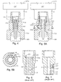
- Figures 5A and 5B schematically show the preferred embodiment of an arrangement to meet the objectives stated above.
- the arrangement of Figures 5A and 5B provide the best features of a CXT and an HXT in a hybrid arrangement, where a valved annulus bypass A5 is provided in the tubing spool TS5, and with a production bore P5 and an increased number of E and H conduits 18 provided therein.
- the tubing spool TS5 is arranged and designed to pass an 81 ⁇ 2" (216 mm) bit. Its top outer profile should be compatible with a standard 18-3 ⁇ 4" (476 mm) system so as to accept a conventional sized CXT and standard sized BOP, as well as a slimbore BOP.
- ID internal profile
- 12-to-14 ports or conduits 18 of 1.50" (38 mm) nominal diameter can be provided in tubing hanger TH5. Of these ports, some may be required for alignment purposes, depending on the alignment method adopted.
- FIGS. I through 5 provide alternative tubing hanger (TH) and xmas tree (XT) combinations which are examined for their capability to meet the objectives as described above.
- the arrangement of Figures 5A and 5B offer certain advantages regarding the desired specific objectives.
- the annulus communication path or passage A5 is routed via the body of the tubing spool TS5 and passes "around" rather than "through” the tubing hanger, as is the case for Figures 1A, 1B and 4.
- a passage is provided around the sealed landing position between the tubing spool TS5 and the tubing hanger TH5.
- This feature provides more space to accommodate a relatively large number of E and H conduits.
- the annulus passage A5 whether integrated with the body of the TS or attached externally by some means, is typically fitted with one or more valves VA5, VA6 in order to enable remote isolation/ sealing of the annulus flow path.
- valved annulus bypass port achieves savings in time and money associated with installing/ retrieving such a plug.
- valves VA5, VA6 of Figure 5A are preferably (but not limited to) gate valves, the reliability of the annulus pressure barrier is also improved with the arrangement of Figure 5A as compared to a wireline plug.
- the annulus bypass conduit A5 is contained as part of a tubing spool assembly TS5 and not in the body of the tree as would be the case for HXTs.
- Tubing spools also called tubing heads, offer advantages and disadvantages.
- Some of the more common characteristics associated with tubing spools include:
- FIG. 5A and 5B An important advantage of the arrangement of Figures 5A and 5B is its capability to pass a very large number of E and H lines 18 through the tubing hanger TH5 white requiring only a very small bore subsea BOP and marine riser.
- a tubing hanger TH5 capable of suspending 4-1/2" (114 mm) production tubing and providing on the order of 10 (combined total) E and H passages 18 of 11 ⁇ 2" (38 mm) diameter can be passed through a roughly 11" (279 mm) bore (drift) BOP stack and an associated "slimbore" marine riser (12" (304 mm) ID).
- a comparably capable HXT tubing hanger system would likely require a 13-5/8" (346 mm) nominal bore BOP and a 14" (355 mm) ID (approximate) bore marine riser.
- the cross sectional area of a 19" (483 mm) bore marine riser (typically used with 18-3/4" (476 mm) bore BOP stacks) is 283.5 in. 2 (1829 cm 2 )
- Cross sectional areas for 14" (355 mm) and 12" (304 mm) risers are 153.9 in. 2 (993 cm 2 ) and 113.1 in. 2 (730 cm 2 ), respectively.
- the volume of fluids required to fill these risers are 100%, 54.3% and 39.9% respectively, using the 19" (483 mm) riser as the base case.
- variable deck loading is improved since smaller risers, less fluid, less fluid storage, etc., all weigh less.
- a 12" bore riser requires only 73.5% as much fluid volume as a 14" (355 mm) riser (a significant advantage for the system of this invention when compared even to reduced bore HXT systems).
- the issue of variable deck loading becomes more important.
- Figures 5A and 5B has characteristics of a conventional xmas tree completion system and an HXT (horizontal xmas tree) completion system. It is a hybrid of features of a CXT and an HXT connected to a well head, but it most closely resembles a CXT with a tubing spool.
- the electric conduits are typically routed through a variety of components (possibly ram and/or annular BOP seal spools, subsea test tree (SSTT)/ emergency disconnect (EDC) latch device, E/H control module, etc.) until they are ultimately combined into a bundle of lines (E and H) typically referred to as an umbilical.
- the umbilical conveniently can be reeled in or out for re-use in a variety of applications.
- one completion scenario associated with the invention is for the landing string (LS, i.e., THRT on "up") to be retrieved, the BOP stack/marine riser disconnected and retrieved, and the xmas tree installed using typically a workover/intervention riser system.
- the xmas tree engages the same E and H control line (wet mateable) couplers at the top of the TH as previously interfaced by the THRT.
- the THRT need only be unlatched from the TH and the LS lifted up into or just above the BOP stack, and the BOP stack need only be removed from the wellhead a sufficient lateral distance to facilitate installation of the xmas tree onto the TS.
- the XT may be lowered by an independent hoisting unit and installed onto the wellhead using a cable or tubing string with ROV assistance, etc., or the xmas tree may previously have been "parked" at a laterally displaced seabed staging position for movement onto the wellhead using the LS and/or BOP stack/ marine riser, for example.
- the procedure for installation of an HXT is different in that it is often preferred that no umbilical be used as part of the TH deployment process.
- the SCSSV(s) are typically locked “open” prior to deployment of the TH, a purely mechanical or “external pressure" (possibly “staged”) operated THRT/TH is employed, and no communication with downhole components is provided.
- a remotely operated vehicle is typically used to engage the various couplers in a radial direction (not a vertical direction) into the TH from the HXT body (horizontal plane of motion).
- ROV remotely operated vehicle
- One supplier also employs "angled" interfacing devices for the hydraulic conduits (i.e., between a tapered lower surface of the TH and a shoulder in the HXT bore) which are engaged passively as part of the TH landing/locking operation.
- the VDB TH schematic of Figure 6 shows a conventional tubing hanger TH6 for a VDB completion system. It shows a production bore P and an annulus bore A and shows that the E and H conduits 18 are routed in a generally vertical manner from the top to the bottom of the tubing hanger TH6.
- a hydraulic coupler 20 and an electric coupler 22 are schematically illustrated.
- the HXT TH schematic of Figure 7 illustrates a tubing hanger TH7 for an HXT with the vertical interface of electric and hydraulic conduits 18' at the bottom of the TH and the generally horizontal or radial couplers 20', 22' interface at the side of the TH.
- FIG. 8 shows such an arrangement with vertical and radial couplers 20"V, 20"H for an electric lead coupler and vertical and radial hydraulic couplers 22"V, 22"H schematically illustrated.
- the arrangement of Figure 8 adds complexity to the system and greatly increases the risk of failure.
- one conduit access point vertical or horizontal
- one conduit access point must be positively de-activated whenever the alternative access point (horizontal or vertical) is active.
- HXT TH8 schematically illustrated in Figure 8 having both vertical and horizontal interfaces is typical of a system actually provided for a subsea application in the Mediterranean Sea.
- HXTs used on natural drive wells have typically required tree caps that can be installed and retrieved through the bore of a BOP stack.
- Electric submersible pump (ESP) equipped HXT wells that cannot produce without artificial lift have been accepted with an "external" tree cap (which also facilitates passage for E and H lines between the TH and HXT mounted control system).
- ESP Electric submersible pump
- External tree cap which also facilitates passage for E and H lines between the TH and HXT mounted control system.
- Great complexity number of functions, orientation, leak paths, etc.
- risk would be added if an "internal" tree cap were required also to conduit E and H controls.
- two caps would likely be required, one through-BOP installable; a second to route the control functions over to the HXT.
- conduits between the external tree cap and the HXT would also be limited regarding the depth of water in which they can be operated, assuming they were to be comprised of flexible hoses. Conduits exposed externally to sea water pressure have a limited "collapse" resistance capability.
- HXTs used on natural drive wells currently require an internal (through-BOP deployed) tree cap further increases the size penalty of HXT systems. This is because the tree cap needs a landing shoulder, seal bores, locking profiles, etc., all of which are generally larger than the diameter of the TH it will ultimately be positioned above.
- the slimbore system of this invention needs to pass nothing larger than the TH, THRT and landing string (LS) through the subsea BOP stack.
- a more or less conventional VDB or alternatively a "monobore" xmas tree can be installed on top of the "slimbore" TS/TH like that of Figures 5A, 5B, because the outer profile of the "slimbore" tubing spool is a conventional 183 ⁇ 4" (476 mm) configuration.
- An associated tree cap for the CXT can be ROV deployed, which saves a trip between the surface and subsea tree, which would normally be required for CXT systems.
- Some advantages of using a subsea completion arrangement that does not include an HXT tree concern relative smaller size and lower weight. These advantages are important for deployment from some deepwater capable rigs. Furthermore, CXTs can be "intervened” using simpler tooting packages deployed from lower cost vessels.
- FIGS 5A, 5B Associated with the slimbore completion system permanently installed hardware (TS, TH, XT, etc.) of this invention as schematically illustrated in Figures 5A, 5B, are a suite of tools that make its installation and subsequent interface effective.
- the installation sequence of Figures 9 to 18 illustrate completion/intervention systems and running tools and methods for these activities.
- Figure 9 shows a conventional subsea wellhead system 100, comprising a high pressure wellhead housing 102 and associated conductor housing and well conductor 104, installed at the subsea mudline 106.
- the internal components of the system 100 including casing hangers/ casing strings and seal assemblies, etc., (not illustrated) are conventional in the art of subsea wellhead systems.
- Figure 10 shows a tubing spool TS10 (also known as a tubing "head”), secured on top of the high pressure wellhead housing 102 by means of a connector C1.
- the connector C1 is preferably a hydraulic wellhead connector which establishes a seal and locks the interface of the tubing spool TS10 to the wellhead housing 102.
- Other securing means can be used in place of the connector C1.
- the tubing spool TS10 provides an upward-facing profile which typically, but not necessarily, matches the profile of the wellhead housing 102.
- the tubing spool TS10 is constructed according to the arrangement illustrated in Figures 5A and 5B. It contains internal profiles and flow paths that are discussed below.
- FIG 11 shows a slimbore BOP stack 120 landed, locked and sealed (by means of hydraulic connector C2) on top of the tubing spool TS10 of Figure 10.
- Slimbore in this context means that the I.D. of the BOP is about 13-5/8" (346 mm).
- Connector C2 is arranged and designed to connect the 13-5/8" (346 mm) nominal slimbore BOP stack to the (typically) 183 ⁇ 4" (476 mm) nominal configuration outer profile of tubing spool TS10.
- the purpose of the BOP stack 120 is primarily to provide well control capability local to the wellhead system components.
- An integral but independently separable part of the slimbore BOP stack is the lower marine riser package (LMRP) 122.
- LMRP lower marine riser package
- LMRP 122 provides for quick release of the marine riser 124 from the slimbore BOP stack 120 in an emergency, such as would be required if the surface vessel to which the marine riser is connected were to move off location unexpectedly.
- LMRP 122 Within the LMRP 122 is a "flex-joint" 123 that eases riser bending loads and the transition angle associated with the interface of the marine riser 124 with the substantially stiffer LMRP 122 and BOP stack 120 components.
- the LMRP 122 also contains redundant control modules, choke and kill line terminations and, typically, a redundant annular blow-out preventer. By retrieving the LMRP 122, any of these items can be repaired or replaced, if the need were to arise, without requiring that the BOP stack 120 be disturbed. This feature is important, because the BOP stack could be required to maintain well control.
- the marine riser 124 itself is the component of the system that enables the BOP stack 120 to be lowered to and retrieved from the high pressure wellhead housing 102 (drilling mode) and tubing spool TS10 at sea floor 106. It is also, however, the conduit through which drilling and completion fluids are circulated, and through which all wellbore tools are deployed.
- the internal diameter of the marine riser defines to a significant extent (especially in deep water) the volume of fluids that must be handled by the associated deployment vessel, and also defines the maximum size of any elements that can pass through the riser.
- the internal diameters of the riser 124, the lower marine riser package 122 and the BOP stack 120 must be sufficient to pass the equipment and tooling that will be run into the bore of the tubing spool TS10 which is designed like the tubing spool TS5 of Figures 5A and 5B.
- the small internal bore diameter of tubing spool TS10 enabled by its arrangement with a tubing hanger having a production bore (but no annulus bore) and an increased number of E and H conduits, determines the minimum size acceptable for the inner diameter of BOP stack 120 :and Lower Marine Riser Package 122 and marine riser 124.
- tubing hanger TH12 (see Figure 12 and Figure 12A) have a maximum external diameter of slightly less than 11" (279 mm) and that the internal bore of BOP stack 120 and LMRP 122 be slightly greater, e.g., 11" (279 mm) drift so as to be able to pass tubing hanger TH12 through them.
- the internal diameter of marine completion riser 124 is preferably about 12" (304 mm).
- tubing hanger TH12 may have a maximum external diameter of slightly less than 13-5/8" (346 mm), with the internal bore of BOP stack 120 and LMRP of slightly greater dimension, 13-5/8" (346 mm) drift, and with the internal diameter of marine completion riser 124 about 14" (355 mm).
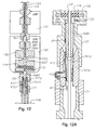
- Figure 12 shows a sectional view of Figure 11.
- Figure 12A shows an enlarged sectional view of Figure 12.
- the tubing hanger, TH12 has been landed, locked and sealed to the bore of the tubing spool TS10.
- the arrangement of tubing hanger/tubing spool TH12/TS10 is like that of TH5/TS5 of the schematic illustrations of Figures 5A, 5B.
- the orientation of the tubing hanger TH12 within the tubing spool TS10 is achieved passively by engagement typically of a tubing hanger - integral key into a tubing spool - fixed cam/ vertical slot device (not shown).
- Alternative passive alignment arrangements are also known to those skilled in the art of well completions.
- the key is preferably located below the tubing hanger TH12 landing shoulder, but another location for such a key may be provided.
- Figure 12 and enlarged portion Fig. 12A further show an annulus path or passage A12 that allows communication of fluids around the tubing hanger TH12 (i.e., from above to below the sealed landing location of TH12/TS10, and vice-versa).
- This "bypass" path A12 is equipped with a remotely operable valve V12 that permits remote control closure of the passage A12 whenever desired, without the need for an associated wireline operation.
- Figure 12A most clearly shows the completion landing string LS made up to the top of the tubing hanger TH12.
- the landing string LS is typically defined as everything above the tubing hanger TH12 as illustrated in Figure 12.
- the subsea test tree SSTT and associated emergency disconnect latch EDCL are positioned above the lowermost BOP stack 120 ram 128 and below the BOP blind/ shear ram 130.
- Such an arrangement is conventional.
- the well annulus can be accessed via port A12 using the BOP stack choke and kill system flow paths 132.
- the communication path is illustrated by arrows AP in Figure 12A. All of these system characteristics cooperate to enable use of a simple, tubing-based slimbore monobore landing string LS and a very small outside diameter (OD) tubing hanger TH12.
- FIG 12B is a perspective view of tubing spool TS10 which shows that the annulus path A12 may include an external piping loop A12' as an alternative to the internal conduit illustrated in Figure 5A.
- the annulus bypass conduit may also reside fully within either a bolt-on or flange-on block attached to the side of the tubing spool TS10.
- Valve V12 is remotely controllable.
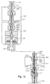
- Figure 13 illustrates the state of the subsea system with the slimbore BOP stack 120/122 removed from the tubing spool TS10 (with the bottom of the landing string LS suspended therein) and offset laterally a relatively small distance from the top of the tubing spool TS10.
- Figure 13 also shows that a subsea xmas tree 150 and BOP adaptor 152 have been installed in place of BOP 120 with connector C3 securing xmas tree 150 to tubing spool TS10.
- Connector C3 connects the xmas tree 150 to the typically 183 ⁇ 4" (476 mm) configuration nominal profile of the tubing spool TS10.
- the xmas tree 150 may be deployed to the tubing spool TS10 by means of a cable in coordination with a ROV, or on drill pipe or tubing, or even using the BOP stack 120 and/or landing string LS themselves as the transport devices. Note that for the case where a conventional size BOP stack is used in place of the slimbore system, it is also conceivable that the BOP stack could be "parked" on top of an appropriate seabed facility (typically a preset pile or another wellhead arrangement) and the LMRP used as the transport tool.
- an appropriate seabed facility typically a preset pile or another wellhead arrangement
- FIG 13 further shows a BOP adaptor 152 removably secured to the top of the conventional xmas tree 150, preferably installed to the top of xmas tree 150 while it was on the vessel prior to deployment. Its purpose is to adapt the upper profile 300 of an otherwise conventional xmas tree (e.g., a 13-5/8" (346 mm) clamp hub or similar profile as compared to a standard 183 ⁇ 4" (476 mm) configuration top interface) for an interface 302 with the larger connector C2, typically 183 ⁇ 4" (476 mm), on the bottom of the slimbore BOP stack 120, or the BOP stack LMRP 122 (with connector C2', for example) or a standard BOP stack 160 or its LMRP 170 (see Figure 17).
- BOP adaptor 152 has a bottom profile of typically 13-5/8" (346 mm) nominal configuration and a top profile 302 of 183 ⁇ 4" (476 mm) nominal configuration.
- FIG 13 illustrates the slimbore BOP stack 120 prior to its connection to the conventional xmas tree 150 by means of the BOP adaptor 152.
- the BOP adaptor 152 has an internal profile that emulates the upper internal profile of the tubing hanger TH12 so that the tubing hanger running tool THRT of landing string LS may be used to "tieback" the production bore of the xmas tree 150.
- the inner profile of the BOP adaptor 152 includes a central production bore and at least "dummy" plural E and H receptacles which match those of the tubing hanger, and also includes an annulus passage.
- the BOP adaptor 152 is arranged and designed to provide all interface/guidance facilities required, such as a guidelineless (GLL) re-entry funnel, if required (not shown).
- GLL guidelineless
- Figure 14 and the enlarged sectional views of Figures 14A, 14B show the slimbore BOP stack 120 and landing string LS after engagement of connector C2 to the top of the BOP adaptor 152 and thereby to the 13-5/8" (346 mm) re-entry hub 151 of xmas tree 150.
- the physical relationship between the landing string LS components and BOP stack 120 are identical to such relationship in Figure 12 (orientation, elevation, etc.).
- Control of the annulus bore is by means of the choke and kill lines 132 of the BOP stack 120 via the annulus port A12 of Figure 12A and of Figures 14 and 14B.
- FIG 15 shows the condition of the subsea well after the landing string LS, BOP stack 120, marine riser 124, and BOP adaptor 152 have been retrieved from the top of the xmas tree 150.
- the BOP adaptor 152 is retrieved during the same trip as retrieval of the BOP stack 120 in order to save a trip. Specifically, there are no dedicated trips (or tools) required for the BOP adaptor 152. It is installed already made up to the xmas tree 150, yet it can be retrieved at the same time as the BOP stack 120 or 160 (see Figure 17 and discussion below) leaving the xmas tree 150 connected to tubing spool TS10. Retrieval of the xmas tree 150 by one approach is simply the reverse of the installation process.
- the BOP adaptor 152 may be secured to the bottom of an appropriate BOP stack 120 or LMRP 122, and the BOP adaptor 152 subsequently connected to xmas tree 150. After appropriate pressure barriers have been established in the wellbore, the xmas tree 50 may be retrieved. A variety of other means may also be employed to achieve securing the well and retrieving the tree (including use of a conventional completion/intervention riser system).
- Figure 16 shows a tree cap 158 installed to the top of the xmas tree 150 re-entry profile 300 as a conventional redundant barrier to the xmas tree swab valves and as a "critical surfaces" protector.
- FIG 17 is essentially the same as Figure 14, with the significant difference that the BOP stack 160 shown is a conventional deepwater 18-3/4" (476 mm) nominal size version.
- the BOP adaptor 152 is connected to the larger BOP stack 160 via the connector C4 attached to the 183 ⁇ 4" (476 mm) configuration profile at the top of the adaptor.
- the BOP adaptor 152 provides a common top profile for interface of both slimbore and conventional BOP stacks.
- Figure 18 is an alternative arrangement for the xmas tree 150 secured to a slimbore tubing spool TS10/tubing hanger TH12 without the BOP adaptor being secured thereto for interface with a traditional approach open-sea completion/intervention riser.
- a tree running tool TRT secures a Lower Workover Riser Package (LWRP) and emergency disconnect package EDP to xmas tree 150.
- LWRP Lower Workover Riser Package
Description
Claims (21)
- A subsea well completion arrangement comprising;
a tubing spool (TS) having a main body with upper and lower ends which are arranged and designed for securement to a wellhead housing (WH,102) at the lower end and to a subsea well drilling or completion device at the upper end,
said tubing spool main body having a bore which defines an internal profile for supporting and restraining a tubing hanger (TH), said profile including a sealing profile, said bore arranged and designed to communicate at an upper end with a bore of said subsea well drilling or completion device and to communicate at a lower end with a bore of said wellhead housing, and
an annulus conduit (A5,A12) which communicates with said tubing spool bore at positions above and below said sealing profile,
characterized by
said tubing spool bore lacking any sideways facing conduits for facilitating production (P) couplings, and
said annulus conduit being independent of the tubing hanger and bypassing the tubing hanger. - The subsea well completion arrangement of claim 1 wherein,
said annulus conduit is fully integral with said main body. - The subsea well completion arrangement of claim 1 wherein,
said annulus conduit includes an external piping loop (A12'). - The subsea well completion arrangement of claim 1 wherein,
said annulus conduit (A12) is disposed at least partially in a block fastened to said main body. - The subsea well completion arrangement of claim 1 wherein,
said internal profile is a slimbore of a diameter suitable to interface a tubing hanger having an outside diameter smaller than 11 inches (279 mm). - The subsea well completion arrangement of claim 1 wherein,
said upper end of said main body has a top connection profile suitable for interfacing a subsea well drilling or completion device of 18¾" (476 mm) nominal bore configuration. - The subsea well completion arrangement of claim 1 wherein,
subsea well drilling or completion device is a BOP stack (120,160), a lower marine riser package (LMRP), or a subsea xmas tree (100). - The subsea well completion arrangement of claim 1, further comprising;
a valve (V2, VA5, VA6, VA12) in said annulus conduit for controlling a flow through said annulus conduit. - The subsea well completion arrangement of any one of claims 1 to 8 wherein,
said tubing hanger (TH) has an external profile which is arranged and designed for being supported by, and oriented , locked, and sealed within said internal profile,
said tubing hanger having an cylindrical body, a bore therein for supporting production or injection tubing to extend downwardly into a bore of said wellhead housing (WH,102), and a plurality of electric (E) and hydraulic (H) bores (18) in said cylindrical body which extend from a top end of said tubing hanger to openings at a bottom end of said tubing hanger for interface with electric cables and hydraulic tubes which extend down into the well. - The subsea well completion arrangement of claim 9, further comprising;
a plurality of vertically oriented electric and hydraulic couplers disposed at a top end of said tubing hanger designed and arranged to couple to said plurality of electric and hydraulic bores (18). - The subsea well completion arrangement of claim 9, wherein said tubing hanger (TH) has no passage for annular fluids provided therein.
- The subsea well completion arrangement of claim 9, wherein said tubing hanger (TH) has only one bore (P,P5) for supporting production or injection tubing therein.
- The subsea well completion arrangement of claim 12, wherein said only one bore (P5) for supporting production or injection tubing is coaxially disposed in said cylindrical body and said plurality of electric and hydraulic bores (18) is disposed in a concentric ring about said only one bore (P5) for supporting production or injection tubing.
- The subsea well completion arrangement of claim 12, wherein said only one bore (P) for supporting production or injection tubing is eccentrically disposed in said cylindrical body and said plurality of electric and hydraulic bores (18) is disposed in a concentric ring about said only one bore (P) for supporting production or injection tubing.
- The subsea well completion arrangement of claim 9, wherein
said lower end of said tubing spool is fastened to said wellhead housing (WH,102), and
said upper end of said tubing spool is fastened to a blow out preventer (BOP) stack (120,160),
said BOP stack is a slimbore BOP stack characterized by a BOP bore that is of substantially smaller diameter than a standard bore of a 18¾" (476 mm) BOP stack, and
said tubing hanger (TH) is characterized by an outer diameter dimensioned to pass through said slimbore BOP stack bore. - The subsea well completion arrangement of claim 15 wherein,
the diameter of said bore of said slimbore BOP stack is about 11 inches (279 mm). - The subsea well completion arrangement of claim 15 wherein,
the diameter of said bore of said slimbore BOP stack is about 13 ⅝ inches (346 mm). - The subsea well completion arrangement of claim 15 further comprising,
a marine riser (124) coupled between said BOP stack (120,160) and a surface vessel, said riser having a slimbore internal diameter which is of substantially smaller diameter than a standard bore of a 19" (483 mm). - The subsea well completion arrangement of claim 15 further comprising,
a ram BOP (128,130),
a choke and kill line (132) below said ram BOP which communicates with said bore of said slimbore BOP stack (120,160),
a marine riser (124) coupled between a surface vessel and said slimbore BOP stack, and a landing string (LS) extending through said marine riser and said bore of said slimbore BOP stack to said tubing hanger,
said tubing spool, said tubing hanger (TH), said BOP stack and said landing string arranged and designed for said ram BOP to close about said landing string, whereby an annulus flow is controlled by said choke and kill line via said annulus conduit in said main body of said tubing spool. - The subsea well completion arrangement of claim 15 further comprising,
a marine riser (124) coupled between a surface vessel and said slimbore BOP stack (120,160),
a landing string (LS) having a bottom end, said landing string extending through said marine riser and said bore of said slimbore BOP stack,
a tubing hanger running tool secured to said bottom end of said landing string, wherein,
said tubing hanger running tool is dimensioned and arranged to pass through said tubing spool for landing said tubing hanger (TH) in said internal profile. - The subsea well completion arrangement of claim 15 wherein,
said lower end of said tubing spool is fastened to said wellhead, and said upper end of said tubing spool is fastened to an xmas tree (XT), said xmas tree having a top standard re-entry profile and having production or injection fluid and annulus fluid paths which communicate with said production or injection tubing and said annulus conduit of said tubing spool,
said arrangement further including,
a BOP adapter (152) having a bottom end secured to said top standard re-entry profile of said xmas tree and an internal profile which includes production or injection fluid and annulus fluid paths which communicate with said production or injection fluid and annulus fluid paths of said xmas tree,
a BOP stack (120,160) secured to a top end of said BOP adapter having a central bore, a ram BOP (128,130), and a choke and kill line (132) disposed below said ram BOP which communicates with said bore of said BOP stack,
a marine riser (124) coupled between said BOP stack and a surface vessel,
a landing string (LS) having a conduit, and a bottom end disposed through said marine riser and said BOP stack, and
a tubing hanger running tool (THRT) coupled to said bottom end of said landing string, having a bottom end designed and arranged to be accepted within said internal profile of said BOP adapter, said tubing hanger running tool establishing a communication path between said conduit of said landing string and said production or injection fluid path of said BOP adapter, wherein
said tubing spool (TS), said tubing hanger (TH), said xmas tree, said BOP adapter, said BOP stack, said landing string and said tubing hanger running tool are arranged and designed for said ram BOP to close about said landing string , whereby an annulus flow is controlled by said choke and kill line.
Priority Applications (2)
| Application Number | Priority Date | Filing Date | Title |
|---|---|---|---|
| EP03014704A EP1350918B1 (en) | 1997-10-07 | 1998-10-07 | A method of completing a subsea well |
| EP03014705A EP1350919B1 (en) | 1997-10-07 | 1998-10-07 | A blow out preventer adapter for subsea well completion |
Applications Claiming Priority (3)
| Application Number | Priority Date | Filing Date | Title |
|---|---|---|---|
| US6129397P | 1997-10-07 | 1997-10-07 | |
| US61293P | 1997-10-07 | ||
| PCT/US1998/021192 WO1999018329A1 (en) | 1997-10-07 | 1998-10-07 | Slimbore subsea completion system and method |
Related Child Applications (2)
| Application Number | Title | Priority Date | Filing Date |
|---|---|---|---|
| EP03014705A Division EP1350919B1 (en) | 1997-10-07 | 1998-10-07 | A blow out preventer adapter for subsea well completion |
| EP03014704A Division EP1350918B1 (en) | 1997-10-07 | 1998-10-07 | A method of completing a subsea well |
Publications (3)
| Publication Number | Publication Date |
|---|---|
| EP1021637A1 EP1021637A1 (en) | 2000-07-26 |
| EP1021637A4 EP1021637A4 (en) | 2002-07-24 |
| EP1021637B1 true EP1021637B1 (en) | 2004-02-11 |
Family
ID=22034846
Family Applications (1)
| Application Number | Title | Priority Date | Filing Date |
|---|---|---|---|
| EP98952151A Expired - Lifetime EP1021637B1 (en) | 1997-10-07 | 1998-10-07 | Slimbore subsea completion system and method |
Country Status (6)
| Country | Link |
|---|---|
| US (3) | US6227300B1 (en) |
| EP (1) | EP1021637B1 (en) |
| AU (1) | AU9791898A (en) |
| BR (1) | BR9812854A (en) |
| NO (5) | NO331355B1 (en) |
| WO (1) | WO1999018329A1 (en) |
Families Citing this family (131)
| Publication number | Priority date | Publication date | Assignee | Title |
|---|---|---|---|---|
| DE69226630T2 (en) * | 1992-06-01 | 1998-12-24 | Cooper Cameron Corp | Wellhead |
| GB2345927B (en) * | 1999-02-11 | 2000-12-13 | Fmc Corp | Subsea completion system with integral valves |
| US6394194B1 (en) * | 1999-04-26 | 2002-05-28 | Abb Vetco Gray Inc. | Method and apparatus for a drill cutting injection system |
| US7111687B2 (en) * | 1999-05-14 | 2006-09-26 | Des Enhanced Recovery Limited | Recovery of production fluids from an oil or gas well |
| GB9911146D0 (en) * | 1999-05-14 | 1999-07-14 | Enhanced Recovery Limited Des | Method |
| GB2348655B (en) * | 1999-08-24 | 2001-05-09 | Fmc Corp | Subsea tree coupling for mudline suspension system |
| GB2358204B (en) * | 2000-01-14 | 2002-09-18 | Fmc Corp | Subsea completion annulus monitoring and bleed down system |
| EP1278936B1 (en) | 2000-03-24 | 2005-06-08 | FMC Technologies, Inc. | Tubing hanger with annulus bore |
| US7025132B2 (en) * | 2000-03-24 | 2006-04-11 | Fmc Technologies, Inc. | Flow completion apparatus |
| GB2361725B (en) | 2000-04-27 | 2002-07-03 | Fmc Corp | Central circulation completion system |
| GB2362398B (en) * | 2000-05-16 | 2002-11-13 | Fmc Corp | Device for installation and flow test of subsea completions |
| US6488093B2 (en) | 2000-08-11 | 2002-12-03 | Exxonmobil Upstream Research Company | Deep water intervention system |
| GB0027269D0 (en) * | 2000-11-08 | 2000-12-27 | Donald Ian | Recovery of production fluids from an oil or gas well |
| US6516861B2 (en) * | 2000-11-29 | 2003-02-11 | Cooper Cameron Corporation | Method and apparatus for injecting a fluid into a well |
| GB0100565D0 (en) * | 2001-01-10 | 2001-02-21 | 2H Offshore Engineering Ltd | Operating a subsea well |
| US20020117305A1 (en) * | 2001-02-23 | 2002-08-29 | Calder Ian Douglas | Cuttings injection and annulus remediation systems for wellheads |
| GB2376487B (en) | 2001-06-15 | 2004-03-31 | Schlumberger Holdings | Power system for a well |
| US6805200B2 (en) * | 2001-08-20 | 2004-10-19 | Dril-Quip, Inc. | Horizontal spool tree wellhead system and method |
| US6659181B2 (en) * | 2001-11-13 | 2003-12-09 | Cooper Cameron Corporation | Tubing hanger with annulus bore |
| US7044227B2 (en) * | 2001-12-10 | 2006-05-16 | Vetco Gray Inc. | Subsea well injection and monitoring system |
| US20030121667A1 (en) * | 2001-12-28 | 2003-07-03 | Alfred Massie | Casing hanger annulus monitoring system |
| NO332026B1 (en) * | 2002-01-30 | 2012-05-29 | Vetco Gray Inc | Underwater wellhead assembly and method of completion and production of a subsea well. |
| AU2003263874A1 (en) * | 2002-08-16 | 2004-03-03 | Dril-Quip, Inc. | Horizontal spool tree wellhead system and method |
| WO2004025074A1 (en) * | 2002-08-22 | 2004-03-25 | Fmc Technologies, Inc. | Apparatus and method for installation of subsea well completion systems |
| US7395866B2 (en) * | 2002-09-13 | 2008-07-08 | Dril-Quip, Inc. | Method and apparatus for blow-out prevention in subsea drilling/completion systems |
| US7028777B2 (en) * | 2002-10-18 | 2006-04-18 | Dril-Quip, Inc. | Open water running tool and lockdown sleeve assembly |
| US6966383B2 (en) * | 2002-12-12 | 2005-11-22 | Dril-Quip, Inc. | Horizontal spool tree with improved porting |
| US6955223B2 (en) * | 2003-01-13 | 2005-10-18 | Helmerich & Payne, Inc. | Blow out preventer handling system |
| US6966381B2 (en) | 2003-04-09 | 2005-11-22 | Cooper Cameron Corporation | Drill-through spool body sleeve assembly |
| NO322829B1 (en) * | 2003-05-22 | 2006-12-11 | Fmc Kongsberg Subsea As | Resealable plug, valve tree with plug and well intervention procedure in wells with at least one plug |
| EP2216503B1 (en) * | 2003-05-31 | 2013-12-11 | Cameron Systems (Ireland) Limited | Apparatus and method for recovering fluids from a well and/or injecting fluids into a well |
| US20040262010A1 (en) * | 2003-06-26 | 2004-12-30 | Milberger Lionel J. | Horizontal tree assembly |
| AU2004257301A1 (en) * | 2003-07-17 | 2005-01-27 | Bhp Billiton Petroleum Pty Ltd | Subsea tubing hanger assembly for an oil or gas well |
| AU2003904183A0 (en) * | 2003-08-08 | 2003-08-21 | Woodside Energy Limited | Method for completion or work-over of a sub-sea well using a horizontal christmas tree |
| US7011159B2 (en) * | 2003-09-16 | 2006-03-14 | Hydril Company, L.P. | Compact mid-grip fastener |
| US7296629B2 (en) * | 2003-10-20 | 2007-11-20 | Fmc Technologies, Inc. | Subsea completion system, and methods of using same |
| US7121346B2 (en) | 2003-11-18 | 2006-10-17 | Cameron International Corporation | Intervention spool for subsea use |
| CA2555403C (en) | 2004-02-26 | 2012-08-21 | Des Enhanced Recovery Limited | Connection system for subsea flow interface equipment |
| BRPI0400926B1 (en) * | 2004-04-01 | 2015-05-26 | Petroleo Brasileiro Sa | Subsea pumping module system and method of installation |
| SG120314A1 (en) * | 2004-09-02 | 2006-03-28 | Vetco Gray Inc | Tubing running equipment for offshore rig with surface blowout preventer |
| US7490673B2 (en) * | 2004-10-06 | 2009-02-17 | Fmc Technologies, Inc. | Universal connection interface for subsea completion systems |
| US7823648B2 (en) * | 2004-10-07 | 2010-11-02 | Bj Services Company, U.S.A. | Downhole safety valve apparatus and method |
| WO2006069372A2 (en) * | 2004-12-22 | 2006-06-29 | Bj Services Company | Method and apparatus to hydraulically bypass a well tool |
| GB2421525B (en) * | 2004-12-23 | 2007-07-11 | Remote Marine Systems Ltd | Improvements in or relating to sub-sea control and monitoring |
| US7424917B2 (en) * | 2005-03-23 | 2008-09-16 | Varco I/P, Inc. | Subsea pressure compensation system |
| US7225877B2 (en) * | 2005-04-05 | 2007-06-05 | Varco I/P, Inc. | Subsea intervention fluid transfer system |
| NO324579B1 (en) * | 2005-12-08 | 2007-11-26 | Fmc Kongsberg Subsea As | Plug pulling tool |
| US7975770B2 (en) * | 2005-12-22 | 2011-07-12 | Transocean Offshore Deepwater Drilling Inc. | Dual-BOP and common riser system |
| US9234393B2 (en) * | 2006-01-24 | 2016-01-12 | Helix Well Ops (U.K.) Limited | Bore selector |
| US7607485B2 (en) * | 2006-01-26 | 2009-10-27 | Vetco Gray Inc. | Tubing hanger and wellhead housing with mating tubing annulus passages |
| WO2007103707A2 (en) * | 2006-03-02 | 2007-09-13 | Shell Oil Company | Systems and methods for using an umbilical |
| US7699110B2 (en) * | 2006-07-19 | 2010-04-20 | Baker Hughes Incorporated | Flow diverter tool assembly and methods of using same |
| US7699099B2 (en) * | 2006-08-02 | 2010-04-20 | B.J. Services Company, U.S.A. | Modified Christmas tree components and associated methods for using coiled tubing in a well |
| GB2440940B (en) * | 2006-08-18 | 2009-12-16 | Cameron Internat Corp Us | Wellhead assembly |
| GB0618001D0 (en) | 2006-09-13 | 2006-10-18 | Des Enhanced Recovery Ltd | Method |
| GB0625526D0 (en) | 2006-12-18 | 2007-01-31 | Des Enhanced Recovery Ltd | Apparatus and method |
| GB0625191D0 (en) | 2006-12-18 | 2007-01-24 | Des Enhanced Recovery Ltd | Apparatus and method |
| DK2102446T3 (en) * | 2007-01-12 | 2019-01-28 | Baker Hughes A Ge Co Llc | Wellhead arrangement and method for an injection tube string |
| US7913754B2 (en) * | 2007-01-12 | 2011-03-29 | Bj Services Company, U.S.A. | Wellhead assembly and method for an injection tubing string |
| US20090071656A1 (en) * | 2007-03-23 | 2009-03-19 | Vetco Gray Inc. | Method of running a tubing hanger and internal tree cap simultaneously |
| US7743832B2 (en) * | 2007-03-23 | 2010-06-29 | Vetco Gray Inc. | Method of running a tubing hanger and internal tree cap simultaneously |
| US8011436B2 (en) * | 2007-04-05 | 2011-09-06 | Vetco Gray Inc. | Through riser installation of tree block |
| US7921917B2 (en) * | 2007-06-08 | 2011-04-12 | Cameron International Corporation | Multi-deployable subsea stack system |
| US20090038804A1 (en) * | 2007-08-09 | 2009-02-12 | Going Iii Walter S | Subsurface Safety Valve for Electric Subsea Tree |
| BRPI0820743A2 (en) * | 2007-12-12 | 2015-06-16 | Cameron Int Corp | Function reel |
| WO2009120935A2 (en) * | 2008-03-28 | 2009-10-01 | Cameron International Corporation | Wellhead hanger shoulder |
| CA2660219C (en) * | 2008-04-10 | 2012-08-28 | Bj Services Company | System and method for thru tubing deepening of gas lift |
| US8322429B2 (en) * | 2008-05-29 | 2012-12-04 | Hydril Usa Manufacturing Llc | Interchangeable subsea wellhead devices and methods |
| US8100181B2 (en) | 2008-05-29 | 2012-01-24 | Weatherford/Lamb, Inc. | Surface controlled subsurface safety valve having integral pack-off |
| US8122964B2 (en) * | 2008-05-29 | 2012-02-28 | Hydril Usa Manufacturing Llc | Subsea stack alignment method |
| DK178357B1 (en) * | 2008-06-02 | 2016-01-11 | Mærsk Olie Og Gas As | Christmas tree for use in a well |
| US9080425B2 (en) | 2008-10-17 | 2015-07-14 | Foro Energy, Inc. | High power laser photo-conversion assemblies, apparatuses and methods of use |
| US9138786B2 (en) | 2008-10-17 | 2015-09-22 | Foro Energy, Inc. | High power laser pipeline tool and methods of use |
| US9347271B2 (en) | 2008-10-17 | 2016-05-24 | Foro Energy, Inc. | Optical fiber cable for transmission of high power laser energy over great distances |
| US9027668B2 (en) | 2008-08-20 | 2015-05-12 | Foro Energy, Inc. | Control system for high power laser drilling workover and completion unit |
| US9669492B2 (en) | 2008-08-20 | 2017-06-06 | Foro Energy, Inc. | High power laser offshore decommissioning tool, system and methods of use |
| US9244235B2 (en) | 2008-10-17 | 2016-01-26 | Foro Energy, Inc. | Systems and assemblies for transferring high power laser energy through a rotating junction |
| US8571368B2 (en) | 2010-07-21 | 2013-10-29 | Foro Energy, Inc. | Optical fiber configurations for transmission of laser energy over great distances |
| US9242309B2 (en) | 2012-03-01 | 2016-01-26 | Foro Energy Inc. | Total internal reflection laser tools and methods |
| US9074422B2 (en) | 2011-02-24 | 2015-07-07 | Foro Energy, Inc. | Electric motor for laser-mechanical drilling |
| BRPI0918403A2 (en) | 2008-08-20 | 2015-11-24 | Foro Energy Inc | method and system for advancing a wellbore using a high power laser |
| US9562395B2 (en) | 2008-08-20 | 2017-02-07 | Foro Energy, Inc. | High power laser-mechanical drilling bit and methods of use |
| US9089928B2 (en) | 2008-08-20 | 2015-07-28 | Foro Energy, Inc. | Laser systems and methods for the removal of structures |
| US9664012B2 (en) | 2008-08-20 | 2017-05-30 | Foro Energy, Inc. | High power laser decomissioning of multistring and damaged wells |
| BRPI0919913A2 (en) * | 2008-10-28 | 2016-02-16 | Cameron Int Corp | underwater completion with a wellhead annular space access adapter |
| US8240387B2 (en) * | 2008-11-11 | 2012-08-14 | Wild Well Control, Inc. | Casing annulus tester for diagnostics and testing of a wellbore |
| US8826994B2 (en) | 2008-12-18 | 2014-09-09 | Cameron International Corporation | Full bore system without stop shoulder |
| US8127852B2 (en) * | 2008-12-23 | 2012-03-06 | Hydril Usa Manufacturing Llc | Interchangeable subsea wellhead devices and methods |
| GB0901807D0 (en) * | 2009-02-04 | 2009-03-11 | Expro North Sea Ltd | Landing string assembly |
| US9845652B2 (en) | 2011-02-24 | 2017-12-19 | Foro Energy, Inc. | Reduced mechanical energy well control systems and methods of use |
| US8720584B2 (en) | 2011-02-24 | 2014-05-13 | Foro Energy, Inc. | Laser assisted system for controlling deep water drilling emergency situations |
| US8684088B2 (en) | 2011-02-24 | 2014-04-01 | Foro Energy, Inc. | Shear laser module and method of retrofitting and use |
| US8783360B2 (en) * | 2011-02-24 | 2014-07-22 | Foro Energy, Inc. | Laser assisted riser disconnect and method of use |
| US8783361B2 (en) | 2011-02-24 | 2014-07-22 | Foro Energy, Inc. | Laser assisted blowout preventer and methods of use |
| CN102713141B (en) | 2009-12-24 | 2017-07-28 | 普拉德研究及开发股份有限公司 | Electric hydraulic interface for Modular downhole tool |
| GB2479552B (en) * | 2010-04-14 | 2015-07-08 | Aker Subsea Ltd | Subsea wellhead providing controlled access to a casing annulus |
| US8479828B2 (en) | 2010-05-13 | 2013-07-09 | Weatherford/Lamb, Inc. | Wellhead control line deployment |
| US8807223B2 (en) | 2010-05-28 | 2014-08-19 | David Randolph Smith | Method and apparatus to control fluid flow from subsea wells |
| CA2808214C (en) | 2010-08-17 | 2016-02-23 | Foro Energy Inc. | Systems and conveyance structures for high power long distance laser transmission |
| US8881829B2 (en) * | 2010-10-07 | 2014-11-11 | David B. Redden | Backup wellhead blowout prevention system and method |
| US8657012B2 (en) * | 2010-11-01 | 2014-02-25 | Vetco Gray Inc. | Efficient open water riser deployment |
| WO2012064380A2 (en) * | 2010-11-08 | 2012-05-18 | Cameron International Corporation | Gasket test protector sleeve for subsea mineral extraction equipment |
| NO334106B1 (en) * | 2011-01-11 | 2013-12-09 | Aker Subsea As | Drill protector for a pipe hanger and its use |
| US8857520B2 (en) * | 2011-04-27 | 2014-10-14 | Wild Well Control, Inc. | Emergency disconnect system for riserless subsea well intervention system |
| NO334816B1 (en) * | 2011-04-28 | 2014-06-02 | Aker Subsea As | The subsea well assembly |
| US8631875B2 (en) | 2011-06-07 | 2014-01-21 | Baker Hughes Incorporated | Insert gas lift injection assembly for retrofitting string for alternative injection location |
| US9670755B1 (en) * | 2011-06-14 | 2017-06-06 | Trendsetter Engineering, Inc. | Pump module systems for preventing or reducing release of hydrocarbons from a subsea formation |
| US20130000918A1 (en) * | 2011-06-29 | 2013-01-03 | Vetco Gray Inc. | Flow module placement between a subsea tree and a tubing hanger spool |
| US9376881B2 (en) * | 2012-03-23 | 2016-06-28 | Vetco Gray Inc. | High-capacity single-trip lockdown bushing and a method to operate the same |
| US8960306B2 (en) * | 2012-12-21 | 2015-02-24 | Hydril Usa Manufacturing Llc | Annular blowout preventer and lower marine riser package connector unit |
| US9650855B2 (en) * | 2013-03-15 | 2017-05-16 | Safestack Technology L.L.C. | Riser disconnect package for lower marine riser package, and annular-release flex-joint assemblies |
| US11156053B2 (en) * | 2013-03-15 | 2021-10-26 | Safestack Technology L.L.C. | Riser disconnect package for lower marine riser package, and annular-release flex-joint assemblies |
| US9631446B2 (en) | 2013-06-26 | 2017-04-25 | Impact Selector International, Llc | Impact sensing during jarring operations |
| US9279308B2 (en) | 2013-08-20 | 2016-03-08 | Onesubsea Llc | Vertical completion system including tubing hanger with valve |
| US9140091B1 (en) * | 2013-10-30 | 2015-09-22 | Trendsetter Engineering, Inc. | Apparatus and method for adjusting an angular orientation of a subsea structure |
| US9611717B2 (en) | 2014-07-14 | 2017-04-04 | Ge Oil & Gas Uk Limited | Wellhead assembly with an annulus access valve |
| US10309190B2 (en) | 2014-07-23 | 2019-06-04 | Onesubsea Ip Uk Limited | System and method for accessing a well |
| USD749644S1 (en) * | 2014-10-28 | 2016-02-16 | David B. Redden | Subsea dual housing assembly |
| US9765593B2 (en) | 2014-12-03 | 2017-09-19 | Ge Oil & Gas Uk Limited | Configurable subsea tree master valve block |
| NO341605B1 (en) * | 2014-12-05 | 2017-12-11 | Vetco Gray Scandinavia As | Landing string for landing a production hanger in a production run in a wellhead |
| US9951602B2 (en) | 2015-03-05 | 2018-04-24 | Impact Selector International, Llc | Impact sensing during jarring operations |
| US9828824B2 (en) * | 2015-05-01 | 2017-11-28 | Hydril Usa Distribution, Llc | Hydraulic re-configurable and subsea repairable control system for deepwater blow-out preventers |
| US10132135B2 (en) * | 2015-08-05 | 2018-11-20 | Cameron International Corporation | Subsea drilling system with intensifier |
| US10221687B2 (en) | 2015-11-26 | 2019-03-05 | Merger Mines Corporation | Method of mining using a laser |
| US11187052B2 (en) * | 2016-12-08 | 2021-11-30 | Kinetic Pressure Control Ltd. | Explosive disconnect |
| WO2018106347A1 (en) * | 2016-12-08 | 2018-06-14 | Kinetic Pressure Control, Ltd. | Explosive disconnect |
| US9945202B1 (en) | 2017-03-27 | 2018-04-17 | Onesubsea Ip Uk Limited | Protected annulus flow arrangement for subsea completion system |
| GB202011951D0 (en) | 2020-07-31 | 2020-09-16 | Baker Hughes Energy Tech Uk Limited | Tubing head spool and method of drilling a well using the tubing head spool |
| US11719065B2 (en) * | 2020-11-13 | 2023-08-08 | Onesubsea Ip Uk Limited | Configurable coupling assembly |
| BR102020026776A2 (en) | 2020-12-28 | 2022-07-12 | Aker Solutions Do Brasil Ltda | ADAPTER TO CONNECT CONCENTRIC CHRISTMAS TREE WITH ECCENTRIC PRODUCTION BASE |
| RU2756756C1 (en) * | 2020-12-30 | 2021-10-05 | Общество с ограниченной ответственностью "Газпром 335" | Combined underwater wellhead equipment |
Citations (1)
| Publication number | Priority date | Publication date | Assignee | Title |
|---|---|---|---|---|
| GB2166775A (en) * | 1984-09-12 | 1986-05-14 | Britoil Plc | Underwater well equipment |
Family Cites Families (17)
| Publication number | Priority date | Publication date | Assignee | Title |
|---|---|---|---|---|
| US3635435A (en) | 1970-03-16 | 1972-01-18 | Lamson & Sessions Co | Breakaway support for rear vision mirror |
| US3653435A (en) * | 1970-08-14 | 1972-04-04 | Exxon Production Research Co | Multi-string tubingless completion technique |
| US4147221A (en) | 1976-10-15 | 1979-04-03 | Exxon Production Research Company | Riser set-aside system |
| US4491176A (en) * | 1982-10-01 | 1985-01-01 | Reed Lehman T | Electric power supplying well head assembly |
| US4607691A (en) | 1984-07-06 | 1986-08-26 | Combustion Engineering, Inc. | Non-orienting, multiple ported, cylindrical pressure transfer device |
| GB8801850D0 (en) | 1988-01-28 | 1988-02-24 | British Petroleum Co Plc | Tubing hanger shut-off mechanism |
| GB9014237D0 (en) * | 1990-06-26 | 1990-08-15 | Framo Dev Ltd | Subsea pump system |
| FR2672935B1 (en) | 1991-02-14 | 1999-02-26 | Elf Aquitaine | UNDERWATER WELL HEAD. |
| DE69226630T2 (en) | 1992-06-01 | 1998-12-24 | Cooper Cameron Corp | Wellhead |
| US5372199A (en) | 1993-02-16 | 1994-12-13 | Cooper Industries, Inc. | Subsea wellhead |
| GB2286840B (en) | 1994-02-10 | 1997-09-03 | Fmc Corp | Safety valve for horizontal tree |
| US5503230A (en) | 1994-11-17 | 1996-04-02 | Vetco Gray Inc. | Concentric tubing hanger |
| US5671812A (en) * | 1995-05-25 | 1997-09-30 | Abb Vetco Gray Inc. | Hydraulic pressure assisted casing tensioning system |
| US5566758A (en) * | 1995-06-07 | 1996-10-22 | Forester; Buford G. | Method and apparatus for drilling wells in to geothermal formations |
| GB9514526D0 (en) * | 1995-07-15 | 1995-09-13 | Expro North Sea Ltd | Lightweight intervention system for use with horizontal tree with internal ball valve |
| US5971077A (en) * | 1996-11-22 | 1999-10-26 | Abb Vetco Gray Inc. | Insert tree |
| US5868204A (en) | 1997-05-08 | 1999-02-09 | Abb Vetco Gray Inc. | Tubing hanger vent |
-
1998
- 1998-10-07 WO PCT/US1998/021192 patent/WO1999018329A1/en active IP Right Grant
- 1998-10-07 EP EP98952151A patent/EP1021637B1/en not_active Expired - Lifetime
- 1998-10-07 AU AU97918/98A patent/AU9791898A/en not_active Abandoned
- 1998-10-07 BR BR9812854-0A patent/BR9812854A/en active IP Right Grant
- 1998-10-07 US US09/168,301 patent/US6227300B1/en not_active Expired - Lifetime
-
2000
- 2000-03-01 NO NO20001035A patent/NO331355B1/en not_active IP Right Cessation
- 2000-07-17 NO NO20003663A patent/NO322545B1/en not_active IP Right Cessation
- 2000-07-17 NO NO20003664A patent/NO318459B1/en not_active IP Right Cessation
- 2000-07-17 NO NO20003666A patent/NO319931B1/en not_active IP Right Cessation
- 2000-07-17 NO NO20003665A patent/NO20003665D0/en not_active Application Discontinuation
- 2000-10-09 US US09/685,831 patent/US6715554B1/en not_active Expired - Lifetime
- 2000-10-09 US US09/685,650 patent/US6408947B1/en not_active Expired - Lifetime
Patent Citations (1)
| Publication number | Priority date | Publication date | Assignee | Title |
|---|---|---|---|---|
| GB2166775A (en) * | 1984-09-12 | 1986-05-14 | Britoil Plc | Underwater well equipment |
Also Published As
| Publication number | Publication date |
|---|---|
| NO20003665D0 (en) | 2000-07-17 |
| EP1021637A4 (en) | 2002-07-24 |
| NO318459B1 (en) | 2005-03-21 |
| NO319931B1 (en) | 2005-10-03 |
| US6227300B1 (en) | 2001-05-08 |
| NO322545B1 (en) | 2006-10-23 |
| NO20001035D0 (en) | 2000-03-01 |
| NO20003664D0 (en) | 2000-07-17 |
| NO20003663D0 (en) | 2000-07-17 |
| NO20003666D0 (en) | 2000-07-17 |
| WO1999018329A1 (en) | 1999-04-15 |
| EP1021637A1 (en) | 2000-07-26 |
| US6408947B1 (en) | 2002-06-25 |
| BR9812854A (en) | 2000-08-08 |
| NO20003663L (en) | 2000-06-05 |
| AU9791898A (en) | 1999-04-27 |
| NO20003666L (en) | 2000-06-05 |
| NO20003665L (en) | 2000-06-05 |
| NO20003664L (en) | 2000-06-05 |
| NO20001035L (en) | 2000-06-05 |
| NO331355B1 (en) | 2011-12-05 |
| US6715554B1 (en) | 2004-04-06 |
Similar Documents
| Publication | Publication Date | Title |
|---|---|---|
| EP1021637B1 (en) | Slimbore subsea completion system and method | |
| US5819852A (en) | Monobore completion/intervention riser system | |
| US6810954B2 (en) | Production flow tree cap | |
| EP0907821B1 (en) | Christmas tree | |
| US7013970B2 (en) | Central circulation completion system | |
| CA2632812C (en) | Apparatus and method for installation of subsea well completion systems | |
| US9976375B2 (en) | Blowout preventer shut-in assembly of last resort | |
| US8297359B2 (en) | Subsea well intervention systems and methods | |
| US6053252A (en) | Lightweight intervention system | |
| US6497286B1 (en) | Method and apparatus for drilling a plurality of offshore underwater wells | |
| EP2917459B1 (en) | Horizontal vertical deepwater tree | |
| US20070034379A1 (en) | Plug installation system for deep water subsea wells | |
| US20130168101A1 (en) | Vertical subsea tree assembly control | |
| US20050121198A1 (en) | Subsea completion system and method of using same | |
| GB2397312A (en) | Well completion system | |
| WO2006061645A1 (en) | Plug installation and retrieval tool for subsea wells | |
| EP1350919B1 (en) | A blow out preventer adapter for subsea well completion | |
| NO343789B1 (en) | Device for enabling removal or installation of a horizontal Christmas tree and methods thereof |
Legal Events
| Date | Code | Title | Description |
|---|---|---|---|
| PUAI | Public reference made under article 153(3) epc to a published international application that has entered the european phase |
Free format text: ORIGINAL CODE: 0009012 |
|
| 17P | Request for examination filed |
Effective date: 20000327 |
|
| AK | Designated contracting states |
Kind code of ref document: A1 Designated state(s): GB IT |
|
| RIC1 | Information provided on ipc code assigned before grant |
Free format text: 7E 21B 33/035 A, 7E 21B 33/038 B, 7E 21B 33/043 B, 7E 21B 33/06 B, 7E 21B 33/047 B |
|
| A4 | Supplementary search report drawn up and despatched |
Effective date: 20020607 |
|
| AK | Designated contracting states |
Kind code of ref document: A4 Designated state(s): GB IT |
|
| RAP1 | Party data changed (applicant data changed or rights of an application transferred) |
Owner name: FMC TECHNOLOGIES, INC. |
|
| 17Q | First examination report despatched |
Effective date: 20021118 |
|
| GRAP | Despatch of communication of intention to grant a patent |
Free format text: ORIGINAL CODE: EPIDOSNIGR1 |
|
| GRAS | Grant fee paid |
Free format text: ORIGINAL CODE: EPIDOSNIGR3 |
|
| GRAA | (expected) grant |
Free format text: ORIGINAL CODE: 0009210 |
|
| AK | Designated contracting states |
Kind code of ref document: B1 Designated state(s): GB IT |
|
| PG25 | Lapsed in a contracting state [announced via postgrant information from national office to epo] |
Ref country code: IT Free format text: LAPSE BECAUSE OF FAILURE TO SUBMIT A TRANSLATION OF THE DESCRIPTION OR TO PAY THE FEE WITHIN THE PRESCRIBED TIME-LIMIT;WARNING: LAPSES OF ITALIAN PATENTS WITH EFFECTIVE DATE BEFORE 2007 MAY HAVE OCCURRED AT ANY TIME BEFORE 2007. THE CORRECT EFFECTIVE DATE MAY BE DIFFERENT FROM THE ONE RECORDED. Effective date: 20040211 |
|
| REG | Reference to a national code |
Ref country code: GB Ref legal event code: FG4D |
|
| PLBE | No opposition filed within time limit |
Free format text: ORIGINAL CODE: 0009261 |
|
| STAA | Information on the status of an ep patent application or granted ep patent |
Free format text: STATUS: NO OPPOSITION FILED WITHIN TIME LIMIT |
|
| 26N | No opposition filed |
Effective date: 20041112 |
|
| PGFP | Annual fee paid to national office [announced via postgrant information from national office to epo] |
Ref country code: GB Payment date: 20171004 Year of fee payment: 20 |
|
| REG | Reference to a national code |
Ref country code: GB Ref legal event code: PE20 Expiry date: 20181006 |
|
| PG25 | Lapsed in a contracting state [announced via postgrant information from national office to epo] |
Ref country code: GB Free format text: LAPSE BECAUSE OF EXPIRATION OF PROTECTION Effective date: 20181006 |