EP3172148B1 - Packet for smoking articles - Google Patents
Packet for smoking articles Download PDFInfo
- Publication number
- EP3172148B1 EP3172148B1 EP15742109.0A EP15742109A EP3172148B1 EP 3172148 B1 EP3172148 B1 EP 3172148B1 EP 15742109 A EP15742109 A EP 15742109A EP 3172148 B1 EP3172148 B1 EP 3172148B1
- Authority
- EP
- European Patent Office
- Prior art keywords
- packaging
- lateral
- internal
- shell
- support shell
- Prior art date
- Legal status (The legal status is an assumption and is not a legal conclusion. Google has not performed a legal analysis and makes no representation as to the accuracy of the status listed.)
- Active
Links
Images


Classifications
-
- B—PERFORMING OPERATIONS; TRANSPORTING
- B65—CONVEYING; PACKING; STORING; HANDLING THIN OR FILAMENTARY MATERIAL
- B65D—CONTAINERS FOR STORAGE OR TRANSPORT OF ARTICLES OR MATERIALS, e.g. BAGS, BARRELS, BOTTLES, BOXES, CANS, CARTONS, CRATES, DRUMS, JARS, TANKS, HOPPERS, FORWARDING CONTAINERS; ACCESSORIES, CLOSURES, OR FITTINGS THEREFOR; PACKAGING ELEMENTS; PACKAGES
- B65D85/00—Containers, packaging elements or packages, specially adapted for particular articles or materials
- B65D85/07—Containers, packaging elements or packages, specially adapted for particular articles or materials for compressible or flexible articles
- B65D85/08—Containers, packaging elements or packages, specially adapted for particular articles or materials for compressible or flexible articles rod-shaped or tubular
- B65D85/10—Containers, packaging elements or packages, specially adapted for particular articles or materials for compressible or flexible articles rod-shaped or tubular for cigarettes
-
- B—PERFORMING OPERATIONS; TRANSPORTING
- B65—CONVEYING; PACKING; STORING; HANDLING THIN OR FILAMENTARY MATERIAL
- B65D—CONTAINERS FOR STORAGE OR TRANSPORT OF ARTICLES OR MATERIALS, e.g. BAGS, BARRELS, BOTTLES, BOXES, CANS, CARTONS, CRATES, DRUMS, JARS, TANKS, HOPPERS, FORWARDING CONTAINERS; ACCESSORIES, CLOSURES, OR FITTINGS THEREFOR; PACKAGING ELEMENTS; PACKAGES
- B65D77/00—Packages formed by enclosing articles or materials in preformed containers, e.g. boxes, cartons, sacks or bags
- B65D77/02—Wrapped articles enclosed in rigid or semi-rigid containers
-
- B—PERFORMING OPERATIONS; TRANSPORTING
- B65—CONVEYING; PACKING; STORING; HANDLING THIN OR FILAMENTARY MATERIAL
- B65D—CONTAINERS FOR STORAGE OR TRANSPORT OF ARTICLES OR MATERIALS, e.g. BAGS, BARRELS, BOTTLES, BOXES, CANS, CARTONS, CRATES, DRUMS, JARS, TANKS, HOPPERS, FORWARDING CONTAINERS; ACCESSORIES, CLOSURES, OR FITTINGS THEREFOR; PACKAGING ELEMENTS; PACKAGES
- B65D85/00—Containers, packaging elements or packages, specially adapted for particular articles or materials
- B65D85/07—Containers, packaging elements or packages, specially adapted for particular articles or materials for compressible or flexible articles
- B65D85/08—Containers, packaging elements or packages, specially adapted for particular articles or materials for compressible or flexible articles rod-shaped or tubular
- B65D85/10—Containers, packaging elements or packages, specially adapted for particular articles or materials for compressible or flexible articles rod-shaped or tubular for cigarettes
- B65D85/1036—Containers formed by erecting a rigid or semi-rigid blank
-
- B—PERFORMING OPERATIONS; TRANSPORTING
- B65—CONVEYING; PACKING; STORING; HANDLING THIN OR FILAMENTARY MATERIAL
- B65D—CONTAINERS FOR STORAGE OR TRANSPORT OF ARTICLES OR MATERIALS, e.g. BAGS, BARRELS, BOTTLES, BOXES, CANS, CARTONS, CRATES, DRUMS, JARS, TANKS, HOPPERS, FORWARDING CONTAINERS; ACCESSORIES, CLOSURES, OR FITTINGS THEREFOR; PACKAGING ELEMENTS; PACKAGES
- B65D5/00—Rigid or semi-rigid containers of polygonal cross-section, e.g. boxes, cartons or trays, formed by folding or erecting one or more blanks made of paper
- B65D5/42—Details of containers or of foldable or erectable container blanks
- B65D5/44—Integral, inserted or attached portions forming internal or external fittings
- B65D5/441—Reinforcements
- B65D5/443—Integral reinforcements, e.g. folds, flaps
-
- B—PERFORMING OPERATIONS; TRANSPORTING
- B65—CONVEYING; PACKING; STORING; HANDLING THIN OR FILAMENTARY MATERIAL
- B65D—CONTAINERS FOR STORAGE OR TRANSPORT OF ARTICLES OR MATERIALS, e.g. BAGS, BARRELS, BOTTLES, BOXES, CANS, CARTONS, CRATES, DRUMS, JARS, TANKS, HOPPERS, FORWARDING CONTAINERS; ACCESSORIES, CLOSURES, OR FITTINGS THEREFOR; PACKAGING ELEMENTS; PACKAGES
- B65D85/00—Containers, packaging elements or packages, specially adapted for particular articles or materials
- B65D85/07—Containers, packaging elements or packages, specially adapted for particular articles or materials for compressible or flexible articles
- B65D85/08—Containers, packaging elements or packages, specially adapted for particular articles or materials for compressible or flexible articles rod-shaped or tubular
- B65D85/10—Containers, packaging elements or packages, specially adapted for particular articles or materials for compressible or flexible articles rod-shaped or tubular for cigarettes
- B65D85/1009—Containers, packaging elements or packages, specially adapted for particular articles or materials for compressible or flexible articles rod-shaped or tubular for cigarettes provided with proffering means
Definitions
- Forms of embodiment described here concern a rigid packet, for smoking articles, such as for example, but not exclusively, cigarettes, or cigars or cigarillos, or similar or comparable smoking articles.
- Traditional packets for cigarettes have a rectangular parallelepiped shape, which extends along a longitudinal axis, and comprise a rigid external packaging defining an external containing body and a lid hinged to the external containing body by means of a hinge.
- An internal packaging is provided to contain the cigarettes, which can be fixed or sliding with respect to the external packaging.
- Hinged lid rigid packets are particularly appreciated by some types of smokers because of their great rigidity, which prevents damage to the cigarettes even when the packet is subjected to knocks or kept in a consumer's pocket or bag.
- the external surface of cigarette packets is printed to impart both the distinctive trademark of the cigarettes, and also the information laid down by the law (for example, identification of the place and date of production, composition of the tobacco, warnings on the dangers of smoking).
- recent laws have considerably increased the size of the space to be reserved for warnings on the dangers of smoking, consequently the space available for the producer of the cigarettes for his distinctive trademark and other information possibly desired has been greatly limited.
- the free surface of the packet would be further reduced since, with a limited number of cigarettes, packets of an equally reduced size tend to be made.
- WO 2005/014436 A1 discloses a rigid packet for smoking articles, provided with an external packaging of the clam-shell type, wherein said external packaging comprises a support shell and a lid shell hinged to the support shell, configured to rotate between an open position, and a closed position, wherein both of said support shell and said lid shell are provided with lateral box-shaped shoulders,wherein, when the lid shell is in the closed position the packaging has a front wall, a back wall, two lateral walls and an upper wall, wherein the lateral walls of the external packaging comprise the lateral box-shaped shoulders.
- the present invention comprises a rigid packet for smoking articles according to claim 1, while the dependent claims describe further embodiments of the invention.
- the rigid packet is provided with an external packaging of the shell-like type and with an internal packaging containing a group of smoking articles.
- the external packaging comprises a support shell to receive the internal packaging and a lid shell hinged to the support shell, configured to rotate between an open position, in which it allows access to the internal packaging, and a closed position.
- the support shell and the lid shell is provided with lateral box-shaped shoulders.
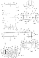
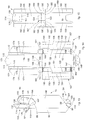
- a rigid packet 10 for smoking articles 12 provided with an external packaging 14 of the shell type and an internal packaging, or collar, 16 containing a group of smoking articles 12.
- smoking articles we mean for example cigarettes, cigars, cigarillos or similar or comparable smoking articles.
- the group of smoking articles 12 can be wrapped in a wrapper or sheet, for example of paper, metalized paper, metal, aluminum, tin foil.
- the internal packaging 16 has a length L, essentially equal or comparable to the length of the smoking articles 12 contained therein (see fig. 6 ).
- the external packaging 14 comprises a support shell 18 with an open front side 20 to receive the internal packaging 16.
- the support shell 18 can include a housing seating 26, accessible through the open front side 20, in order to house the internal packaging 16. Therefore, through the open front side 20 it is possible to access frontally the internal packaging 16 and therefore the smoking articles 12 contained therein.
- the external packaging 14 comprises a lid shell 22 hinged to the support shell 18, with a shape mating to that of the open front side 20 of the support shell 18 and configured to rotate between an open position, in which it allows access to the internal packaging 16 through the open front side 20, and a closed position, which completely covers the open front side 20.
- At least one, or both, of either the support shell 18 or lid shell 22 is provided with one or more lateral box-shaped shoulders 24, 341, 351.
- the support shell 18 can be provided with the one or two lateral box-shaped shoulders 24, 341, 351 to delimit the housing seating 26 to receive the internal packaging 16. It is possible, for example, that only the support shell 18 is provided with the one or more lateral box-shaped shoulders 24, 341, 351, or that the one or more lateral box-shaped shoulders 24, 341, 351 are present both on the support shell 18 and on the lid shell 22, in both cases delimiting the housing seating 26 of the support shell 18.
- the one or more lateral box-shaped shoulders 24, 341, 351 are present only on the lid shell 22.
- the housing seating 26 of the support shell 18 can be delimited by the peripheral walls thereof.
- the housing seating 26 of the support shell 18 can have a height H (see fig. 6 ).
- the height H defines the height available for the positioning of the internal packaging 16. Therefore, in some forms of examples which do not form a part of the invention the height H of the housing seating 26 can be essentially equal to or greater than the length L of the internal packaging 16.
- both the lid shell 22 and the support shell 18 are provided with respective tops 28 and edges 30 that can be associated in pairs with respect to each other, in the closed position of the lid shell 22.
- At least a pair of the tops 28 and edges 30 is formed by a respective top 28 and a respective edge 30 with beveled or rounded profile.
- This shape of the tops 28 and edges 30 is completely new and original in this field.
- An important advantage of this beveled or rounded shape of the tops 28 and edges 30 can be that the latter are less subject to wear and deterioration compared to edges and tops that, for example, have a sharp angle profile.
- a packet 10 provided with such tops 28 and edges 30 can be less awkward to carry for a consumer, in particular in pockets or bags, since thanks to these profiles of the tops 28 and edges 30, they are less likely to get stuck or caught when put into or taken out of the pockets. Furthermore, thanks to the beveled or rounded profile with which with these tops 28 and edges 30 can be provided, the packet 10 deforms and marks the pockets or bags in which it is placed to a much lesser degree.
- the shape and profile of the tops 28 and edges 30 of the packet 10, in combination with the type of packet with external packaging 14 shaped like a shell and internal packaging 16 at least partly extractable, as will be explained in more detail hereafter, can contribute to supplying packets that are appealing both to more traditional and conservative consumers and also to more innovative consumers, the young or more creative type, without upsetting consumers' habits and behaviors.
- two, or three, or four pairs of tops 28 and edges 30 can be provided, each formed by a respective top 28 and a respective edge 30 with a beveled or rounded profile.
- two, three, four pairs each formed by a top 28 and an edge 30 which have a beveled or rounded profile can be provided, for example which are rounded.
- 1, 2, 3, 4 , 6 , 9, 10 , 11, 12 , 16 , 18, 19 , 24 , 26, 27 , 32 , 34, 35 are used to describe forms of examples which do not form a part of the invention in which all the tops 28 and edges 30 of the packet 10 are provided with beveled or rounded profile, for example rounded.
- At least one pair of the tops 28 and edges 30 of the packet 10 is formed by a respective top 28 and a respective edge 30 with a sharp angle profile, in particular square, or at 90°.
- two, three, four pairs can be provided each formed by one top 28 and one edge 30 that have this profile, for example with a sharp angle.
- figs. 37, 38 , 39, 40 are used to describe the invention in which all the tops 28 and edges 30 of the packet 10 are provided with a sharp angle profile, in particular square, or at 90°.
- the lateral box-shaped shoulders 24 develop extending between respective upper and lower edges 30 of the support shell 18.
- one or more lateral box-shaped shoulders 24 can be longitudinal.
- the one or more lateral box-shaped shoulders 24 can develop extending longitudinally between respective pairs of upper and lower edges 30 of the support shell 18.
- the one or more lateral box-shaped shoulders 24 can be transverse.
- the lateral box-shaped shoulders 24 can develop extending transversely between two upper edges 30 and/or between two lower edges 30 of the support shell 18.
- a single lateral box-shaped shoulder 24 can be provided disposed transverse that extends transversely between two lower edges 30 (see for example figs. 32- 36 ).
- two longitudinal lateral box-shaped shoulders 24 can be provided and one transverse lateral box-shaped shoulder 24, or two transverse lateral box-shaped shoulders 24 and one longitudinal lateral box-shaped shoulder 24, or even two longitudinal lateral box-shaped shoulders 24 and two transverse lateral box-shaped shoulders 24.
- the profile of the tops 28 and edges 30 is a rounded angle.
- a rounded angle profile of said tops 28 and edges 30 can be provided, with a radius of curvature R comprised between 3 mm and 5 mm (see figs. 1a and 6a ).
- the radius of curvature R can be 3mm (indicated as Rl), 3.5 mm, 4 mm (indicated as R2), or 4.5 mm, or 5 mm (indicated as R3).
- the rigid packet 10 can be made starting from a sheet of material, such as cardboard, rigid cardboard, millboard, paper or similar relatively rigid materials, suitably shaped and worked.
- Figs. 1, 2, 3 and 4 are used to describe forms of examples which do not form a part of the invention, which can be combined with all the forms of forms of examples which do not form a part of the invention, described here, of the rigid packet 10 with the lid shell 22 in a closed position, which has the tops 28 with a rounded angle profile.
- the lid shell 22 which can have for example an essentially rectangular shape, can be provided with a lower base 32, an upper base 34 and two lateral edges 36 (see for example figs. 1, 2, 3 and 4 ) that delimit an internal front face 38 and an external front face 40 (see figs. 6, 7, 8 , 11 and 12 ).
- the tops 28 with a rounded angle profile of the lid shell 22 can therefore be four tops with a rectangular shape of the lid shell 22.
- the lid shell 22 can be hinged to the support shell 18 by means of a hinge or articulation 42 (see figs. 2 , 6, 7, 8 , 11 and 12 ) around which the lid shell 22 and the support shell 18 can reciprocally rotate.
- the lid shell 22 can be hinged to the support shell 18 in correspondence to the upper base 34 which can therefore define, in cooperation with an upper wall 46 of the support shell 18, the above cited hinge 42.
- the lid shell 22 can be hinged to the support shell 18 in correspondence to the lower base 32, which can therefore define the hinge 42, in cooperation with a lower wall 58 of the support shell 18.
- the rigid packet 10 can be provided with an adhesive flap 44 of the flexible type, for example a tongue, a tab, an adhesive wing, in order to releasably connect the lid shell 22 to the support shell 18 in the closed position (see also figs. 2, 3, 4 , 9 and 10 ).
- the adhesive flap 44 can be affixed on the lower part of the lid shell 22, for example provided in correspondence to the lower base 32 of the lid shell 22, in particular astride the lower base 32.
- the adhesive flap 44 can also be protruding from the lid shell 22 in order to be folded and applied to the support shell 18 (see for example fig. 3 ). In other possible implementations, the adhesive flap 44 can be affixed laterally, in correspondence to one or the other or both lateral edges 36, in particular astride them. The adhesive flap 44 can also be used as holding and traction portion, to start or complete the opening of the lid shell 22.
- other members for holding the lid shell 22 to the support shell 18 can be provided instead of the adhesive flap 44, for example holding elements with mechanical interference, same shape coupling, attachment, snap-in connection.
- other holding and traction elements can be provided instead of the adhesive flap 44, such as protruding fins, grips or other similar members integrated for example in the lid shell 22.
- Figs. 2, 3 and 4 are used to describe forms of examples which do not form a part of the invention, which can be combined with all the forms of embodiment described here, of the rigid packet 10 provided with lid shell 22 and support shell 18, respectively provided with tops 28 and edges 30 with a rounded angle profile.
- the support shell 18 can be provided with said upper wall 46, which has an upper edge 48 hinged to the lid shell 22, in particular to the upper base 34 of the latter.
- the upper wall 46 can have a rectangular shape, provided with said upper edge 48, a lower edge 50 and lateral edges 52 that peripherally delimit the upper wall 46.
- the support shell 18 can be provided with a back wall 54, from which the upper wall 46 and the lower wall 58 project. Moreover, the support shell 18 can be provided with external lateral walls 56, that project from the back wall 54, peripherally delimiting the support shell 18 together with the upper wall 46 and the lower wall 58.
- the lower wall 58 can be double thickness.
- the external lateral walls 56 are connected at the top and bottom, respectively, to the upper wall 46 and to the lower wall 58 by connection walls 60 that define the edges 30 of the support shell 18.
- the connecting walls 60 can be walls with rounded, beveled and/or curved surfaces, to define edges 30 with a rounded angle profile, in particular with the desired radius of curvature R, R1, R2, R3.
- the connecting walls 60 can have a complex curved surface, or an inclined planar surface, or a broken surface, formed by portions of planar surfaces inclined consecutively with respect to each other, for example to define a sharp angle, or a mixed surface, formed by curved segments and planar segments.
- the lid shell 22 can be completely flat, or in other forms of examples which do not form a part of the invention, the lid shell 22 can have one or more inclined or protruding portions or segments.
- figs. 2, 3 and 4 are also used to describe forms of examples which do not form a part of the invention, which can be combined with all the forms of examples which do not form a part of the invention, described here, in which the lid shell 22 comprises a front wall 61.
- the front wall 61 can be provided laterally with inclined wings or fins 62 which extend laterally from a lesser front planar wall 64.
- the lesser front planar wall 64 and the inclined wings or fins 62 can define, in these forms of examples which do not form a part of the invention, the lid shell 22 provided with an internal front face 38 and an external front face 40.
- the inclined wings or fins 62 can be folded so as to be inclined toward the inside of the support shell 18 when the lid shell 22 is in the closed position, that is, they can be divergent from the outside toward the inside of the rigid packet 10.
- the inclined wings or fins 62 can be inclined at the same angle, that is, they can be symmetrical with respect to a center line M of the rigid packet 10.
- the inclined wings or fins 62 can define a "squashed roof' shape of the lid shell 22 (see for example figs. 2 and 4 ).
- the inclined wings or fins 62 can have multiple thickness, for example double compared to the lesser front planar wall 64, for example formed by two longitudinal slats or flaps folded on each other (see for example figs. 2 and 4 ).
- the support shell 18 can be provided with inclined abutment profiles 66, 68 provided to delimit the connecting walls 60, respectively as a lateral continuation of the upper wall 46 and lower wall 58.
- the inclined wings or fins 62 of the lid shell 22 can therefore rest, in the closed condition, against the inclined abutment profiles 66, 68. The latter, therefore, are made in a shape and inclination mating with the inclined wings or fins 62.
- Fig. 5 is used to describe forms of examples which do not form a part of the invention, which can be combined with all the forms of examples which do not form a part of the invention, described here, of the rigid packet 10 that has the cited lateral box-shaped shoulders 24, which can be hollow internally and have a polygonal cross section, for example quadrangular, in particular rectangular or square, and, for example, can be defined or delimited, by said external lateral walls 56, by respective external lateral longitudinal bands 70 of the back wall 54, by internal lateral walls 72 and by internal lateral bands 74.
- the internal lateral walls 72 are parallel and facing opposite the external lateral walls 56, while the internal lateral bands 74 are disposed transversely between the internal lateral walls 72 and the external lateral walls 56.
- the internal lateral bands 74 can be provided to receive the lid shell 22 in abutment in the closed position.
- the inclined wings 62 of the lid shell 22 can rest on the internal lateral bands 74 when the lid shell 22 is rotated toward the support shell 18, in order to be closed like a shell.
- the external lateral wall 56, external lateral band 70, internal lateral wall 72 and internal lateral band 74 are disposed orthogonal and consecutive to each other like a box, delimiting internally a respective cavity 76, which in this case is, for example, longitudinal with respect to the development of the rigid packet 10, that is, it is a longitudinal cavity.
- the inclined wings or fins 62 of the lid shell 22 can rest on an external edge 84 of the lateral box-shaped shoulders 24, formed in particular by a respective internal lateral band 74 and an external lateral band 56.
- Each of the lateral box-shaped shoulders 24 can have an anchoring wall 78, which can be formed for example by a more internal lateral band, in orthogonal continuation of the respective internal lateral walls 72.
- Each anchoring wall 78 can be constrained inside the support shell 18, for example by means of adhesive, such as dots or strips of glue.
- each anchoring wall 78 can be constrained, in the housing seating 26, for example to an internal rear face 80 of the back wall 54 of the support shell 18.
- the anchoring walls 78 can be parallel to the internal lateral bands 74, however not facing opposite these, but offset laterally, as they are folded transversely to the outside, that is, not inside the cavity 76, for the attachment to the internal rear face 80.
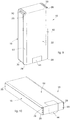
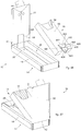
- Fig. 5 is also used to describe forms of examples which do not form a part of the invention, of the internal packaging 16 that contains the group of smoking articles 12 and can have a parallelepiped shape, that is, prismatic with an essentially rectangular base, in particular with a box-like shape.
- the internal packaging 16 can be provided with a front wall 86, a bottom wall 85, a back wall 88 and lateral walls 90.
- the lateral walls 90 can have multiple thicknesses.
- the front wall 86, back wall 88 and lateral walls 90 are, in particular, disposed orthogonally and consecutive to each other to define a containing seating 92 to receive the group of smoking articles 12, which therefore has an essentially rectangular cross section (see for example fig. 13 ).
- the internal packaging 16 can be positioned in the housing seating 26 of the support shell 18, intermediate between the lateral box-shaped shoulders 24.
- the internal packaging 16 can be positioned freely in the housing seating 26, that is, it can be completely extractable, or in a constrained way, that is, so as not to be completely removable from the housing seating 26, but being extractable only partly and, reversibly, being able to be reintroduced into the housing seating 26.
- the internal packaging 16 is disposed laterally adjacent in contact with the lateral box-shaped shoulders 24.
- the lateral walls 90 of the internal packaging 16 can be disposed laterally adjacent in contact against the internal lateral walls 72 of the lateral box-shaped shoulders 24. Therefore, the lateral box-shaped shoulders 24 contain laterally and position stably the internal packaging 16, preventing unwanted movements thereof and thus being able to protect the group of smoking articles 12.
- the presence of the lateral box-shaped shoulders 24 renders the edges 30 more rigid which, otherwise, would be more sensitive, in the event of knocks or accidental or unwanted pressures, to deformations, and therefore would no longer have their beveled or rounded profile, for example rounded.
- the lateral box-shaped shoulders 24 occupy the zone of the support shell 18 in correspondence to the tops 28 and edges 30, and therefore, they protect the smoking articles in the internal packaging 16 so that the more external or lateral smoking articles do not go into contact with the surfaces that delimit internally the tops 28 and edges 30, preventing them becoming squashed or deformed at the ends by the beveled or rounded profile.
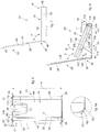
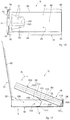
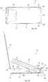
- Figs. 6, 7 and 8 are used to describe forms of embodiment of the rigid packet 10 in an open position, in which the lid shell 22 is rotated and lifted with respect to the support shell 18 and the group of smoking articles 12 contained in the internal packaging 16 is thus directly accessible.
- the internal packaging 16 can have a front opening 94 to facilitate access to the group of smoking articles 12.
- the lid shell 22 is rotatable with respect to the support shell 18 around the hinge 42 as indicated by the arrow F in figs. 7 and 8 , in order to be moved between the closed position and the open position.
- the internal packaging 16 can be extracted from the external packaging 14, in particular rotatable or liftable upward when the lid shell 22 is in its turn open and lifted. This aspect allows to remove the smoking articles 12 from the internal packaging 16.
- the internal packaging 16 can have a length L less than the height H of the housing seating 26, so that when it is positioned in the support shell 18, for example resting against the lower wall 58, a free space 98 is defined, for example a head space, in the housing seating 26 (see fig. 6 ).
- the free space 98 has a height C essentially equal to the difference between the height H and the length L and width essentially equal to the width of the rigid packet 10, given the same thicknesses of the material.
- the free space 98 can be provided as a travel space of the internal packaging 16 along the housing seating 26, so that it can rotate and lift and extract the internal packaging 16 from the support shell 18, so as to remove the smoking articles 12.
- the internal packaging 16 is housed in a freely extractable way in the housing seating 26, or a mechanical extraction and insertion system can be provided that provides a holding of the internal packaging 16, which for example can be actuated manually by the user.
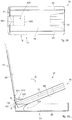
- the internal packaging 16 can be connected in an articulated way to the external packaging 14, and in particular to the support shell 18, by means of a connection unit 100 configured to rotatably connect the internal packaging 16 to the support shell 18.
- connection unit 100 can be configured to allow at least a rotation of the internal packaging 16, as indicated by arrow G in fig. 8 , and possibly also a translation, as indicated by arrow T in fig. 7 , to extract and reposition the internal packaging 16 with respect to the external packaging 14, so as to limit the lifting travel in extraction of the internal packaging 16, holding it with respect to the support shell 18 so it does not completely come out.
- connection unit 100 it is possible to roto-translate the internal packaging 16 along the housing seating 26, in order to lift it (arrows G and T), thus limiting the lifting travel.
- the internal packaging 16 travels a linear extraction path defined by the height C of the free space 98, so that it can subsequently rotate, at least by a desired angle, which can for example be from 15° to 30°, in particular from 20° to 25°, the internal packaging 16 toward the outside around a theoretical hinging fulcrum, located for example in correspondence to the bottom of the rigid packet 10, without interference with the support shell 18, in particular without interference with the lower wall 58 (see for example figs. 6, 7 and 8 ).
- the hinging fulcrum of the internal packaging 16 is in an opposite position to the hinge 42 that defines the articulation between the lid shell 22 and support shell 18.
- the internal packaging 16 can be hinged to the support shell 18 so that its direction of rotation in lifting/lowering (arrow G in fig. 8 ) is opposite the respective direction of rotation in lifting/lowering (arrow F in fig. 8 ) of the lid shell 22.
- the internal packaging 16 and the rotating lid 22 are connected rotatably to the support shell 18 so as to be lifted, and respectively lowered, on opposite sides from each other, for example one in a clockwise direction and the other in an anti-clockwise direction, or vice versa.
- connection unit 100 of the mechanical extraction and insertion system that holds the internal packaging 16 with respect to the support shell 18 is configured to define a push and slide movement, that is, a movement by means of which the internal packaging 16 is pushed sliding along the housing seating 26, thanks to the presence of the free space 98 and, once pushed and translated, can be lifted by means of rotation.
- the rotation can occur with respect to a fulcrum that is in an opposite position to the hinge 42.
- the internal packaging 16 can have at the lower part, on the front wall 86, a thrust zone 99 (see for example figs. 11 and 12 ).
- the thrust zone can be formed for example by a label, tongue, flap or similar element, applied for example by means of adhesive, on the internal packaging 16.
- the thrust zone 99 can be subjected to thrust stresses by the user, for example using a finger, to actuate the push and slide mechanism described above.
- the thrust zone 99 can be made of a material that offers a friction surface on which the user's finger can act.
- connection unit 100 can include a holding member 102, configured to limit the lifting and rotation travel of the internal packaging 16.
- connection unit 100 can include a hinging member 104 configured to constrain the internal packaging 16 in an articulated manner to the support shell 18, for example in correspondence to the lower wall 58 of the support shell 18.
- a hinging member 104 configured to constrain the internal packaging 16 in an articulated manner to the support shell 18, for example in correspondence to the lower wall 58 of the support shell 18.
- only the hinging member 104 may be provided, while in other variants only the holding member 102 can be provided (see for example figs. 25 and 29 ).
- the holding member 102 can be connected rotatably on one side to the back wall 88 of the internal packaging 16, for example in an intermediate zone, comparable to central, or between the center and the upper part, of the back wall 88 ( figs. 8 and 17 ), or again in a lower zone ( fig. 25 ).
- the holding member 102 can be connected rotatably to the internal rear face 80, which delimits the bottom of the housing seating 26, of the back wall 54 of the support shell 18, in particular connected to an intermediate zone, comparable to central, or between the center and the upper part, of the internal rear face 80 ( figs. 8 and 17 ), or again in a lower zone ( fig. 25 ).
- connection of the holding member 102 to the internal rear face 80 can be obtained by adhesive, for example dots or strips of glue, instead the connection to the back wall 88 of the internal packaging 16 can be obtained by making the holding member 102 in a single piece with the internal packaging 16, and possibly refolding one of its components and connecting it, by means of glue for example, to the back wall 88 of the internal packaging 16.
- the holding member 102 can be configured as an articulated holding member with a multiple folding line, for example double or triple.
- the holding member 102 can be a tongue or strip with several predefined folding lines.
- the holding member 102 can comprise a first constraint flap 106 (see for example fig. 8 ), which for example can be connected to the back wall 88 of the internal packaging 16 by means of a first folding line 107, for example in the case where the first constraint flap 106 is made in a single piece with the internal packaging 16, and/or can be constrained using adhesive, that is, glued by means of dots or strips of glue, to the back wall 88.
- the first flap 106 is attached adherent to the back wall 88 with all its surface, without detaching or rotating with respect thereto, as well as being made in a piece and connected to the back wall 88 by means of the first folding line 107.
- the holding member 102 can comprise a rotation flap 108 connected to the first constraint flap 106 by means of a second folding line 110 and a second constraint flap 112 connected to the rotation flap 108 by means of a third folding line 114 and connected to the internal rear face 80 of the back wall 54 of the support shell 18, for example by means of adhesive, that is, glued by means of dots or strips of glue.
- the second constraint flap 112 too can be attached to the internal rear face 80 without detaching from it, as described with regard to the attachment of the first constraint flap 106 to the back wall 88.
- first folding line 107, second folding line 110 and third folding line 114 can be made as incised or punched lines in segments, or pre-creased lines, or pre-creased lines in segments.
- the first constraint flap 106 and the second constraint flap 112 are folded around the second folding line 110 and third folding line 114, on opposite sides with respect to the rotation flap 108. Therefore, the first constraint flap 106, rotation flap 108 and second constraint flap 112 can define, overall, a "Z" or "zig-zag” configuration, which holds the internal packaging 16 with respect to the support shell 18, while still allowing the rotation thereof for the lifting/lowering (arrow G) and for the forward/backward movement (arrow T).
- the hinging member 104 can be configured as an articulated hinging member with multiple fold line, double for example.
- the hinging member 104 can be a tongue or strip with predefined folding lines.
- the hinging member 104 can be connected rotatably on one side to a lower edge 116 of the bottom wall 85 of the internal packaging 16 and, on another side, it can be connected to a lower zone of the internal rear face 80 of the back wall 54 of the support shell 18.
- connection of the hinging member 104 to the internal rear face 80 can be obtained using adhesive, for example dots or strips of glue, instead the connection to the internal packaging 16 can be obtained by making the hinging member 104 in a single piece with the internal packaging 16.
- the hinging member 104 comprises a rotation flap 118 which, for example, can be connected to the lower edge 116 of the internal packaging 16 using a first folding line 120, for example in the case where the rotation flap 118 is made in a single piece with the internal packaging 16, and/or it can be constrained by using adhesive, that is, glued by means of dots or strips of glue, to the lower edge 116.
- the hinging member 104 can comprise a constraint flap 122 connected to the rotation flap 118 by means of a second folding line 124 and connected in a lower zone of the internal rear face 80 of the back wall 54 of the support shell 18, for example using adhesive, that is, glued using dots or strips of glue.
- first folding line 120 and second folding line 124 can be made as incised or punched lines in segments, or pre-creased lines, or pre-creased lines in segments.
- the rotation flap 118 and the constraint flap 122 can be folded around the first folding line 120 and second folding line 124, in order to allow the lifting of the internal packaging 16 by means of rotation around a fulcrum essentially defined in the lower part of the support shell 18, that is, in an opposite position with respect to the hinge 42 which defines the rotatable connection between lid shell 22 and support shell 18.
- Figs. 9 and 10 are used to describe forms of examples which do not form a part of the invention, which can be combined with all the forms of examples which do not form a part of the invention, described here, in which the rigid packet 10 is in a closed condition with the lid shell 22 rotated resting against the support shell 18. In this condition, access to the internal packaging 16, and thus to the smoking articles 12 contained therein, is prevented. In particular, in the closed condition the lid shell 22 is disposed essentially parallel to the adjacent support shell 18.
- the adhesive flap 44 located on the lid shell 22 cooperates with the support shell 18, rendering the coupling stable. The protruding portion of the adhesive flap 44 can be gripped and pulled by the user to lift the lid shell 22.
- Figs. 11 and 12 are used to describe forms of examples which do not form a part of the invention, which can be combined with all the forms of examples which do not form a part of the invention, described here, in which the rigid packet 10 is in an open condition, with the lid shell 22 lifted and rotated with respect to the support shell 18. In this condition, access to the internal packaging 16 and to the smoking articles 12 contained therein is allowed.
- figs. 11 and 12 are also used to describe forms of examples which do not form a part of the invention, in which the internal packaging 16 is partly extracted, in particular rotated and lifted, with respect to the support shell 18, and it can be connected to the support shell 18 by means of the connection unit 100 comprising the hinging member 104 and the holding member 102.
- adhesive elements 126 can be provided, for example dots or strips of glue, on the internal front face 38 of the lid shell 22 (see for example figs. 11 and 12 ).
- the adhesive elements 126 are provided to constrain the lid shell 22 to the internal packaging 16 in the closed condition described for example with reference to figs. 9 and 10 .
- Fig. 13 is used to describe forms of embodiment of the internal packaging or collar 16, formed by front wall 86, bottom wall 85, back wall 88 and lateral walls 90 which delimit the containing seating 92 of the smoking articles 12, which can have the holding member 102 and the hinging member 104 made in a piece with the internal packaging 16.
- the internal packaging 16 provides the holding member 102 made in material continuity with the back wall 88.
- Two longitudinal eyelets 128 are provided in the back wall 88 which define a first strip 130 connected to the back wall 88 by means of the first folding line 107.
- the first strip 130 also has the second folding line 110 and the third folding line 114, which define the first constraint flap 106, the rotation flap 108 and the second constraint flap 112.
- the internal packaging 16 provides the hinging member 104 made in material continuity with the front wall 86 extending from the lower edge 116 thereof.
- Two longitudinal notches 132 are provided made in the bottom wall 85 and in the back wall 88 (see fig. 12 ) which define a second strip 134 connected to the bottom wall 85 by means of the first folding line 120.
- the second strip 134 also has the second folding line 124 which defines the rotation flap 118 and the constraint flap 122.
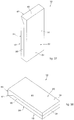
- Fig. 14 is used to describe forms of examples which do not form a part of the invention, which can be combined with all the forms of embodiment described here, of a blank 140, usable to make the external packaging 14 including the support shell 18 and lid shell 22, rotatably connected to each other by means of the hinge 42.
- the external packaging 14 is made from a single blank 140.
- the blank 140 includes a main support panel 142, a lid main panel 144, an upper panel 146, a first lower panel 148 and a second lower panel 150.
- the first lower panel 148 is connected on one side to a short side of the main support panel 142 by a folding line 147 and on the other side to the second lower panel 150 by a folding line 149.
- the upper panel 146 is connected on one side to another short side of the main support panel 142 by a folding line 163, in the opposite position to the first lower panel 148, and on the other side to a short side of the lid main panel 144 by a folding line 165.
- Internal lateral panels 152 are also provided, connected to the long sides of the main support panel 142 by folding lines 151, and external lateral panels 157 connected to the internal lateral panels 152 by folding lines 153.
- each of the external lateral panels 157 is formed by an internal slat 154, connected to an adjacent internal lateral panel 152 by a folding line 153, an intermediate slat 156, connected on one side to the internal slat 154 by a folding line 155 and on another side to an external slat 158 by a folding line 160.
- the folding lines 153, 155, 160 can be made as incised or punched lines in segments, or pre-creased lines, or pre-creased lines in segments.
- Each internal lateral panel 152 can have a lower shaped fin 162 and an upper shaped fin 164, respectively connected to the internal lateral panel 152 by means of upper 166 and lower 168 intermediate shaped connectors.
- the internal slats 154 have shaped free edges 167, rounded for example, mating in shape to the shape of the edges 30.
- the main support panel 142 has shaped tops 169, for example rounded, which are also mating to the shape of the edges 30.
- the blank 140 also comprises internal slats 170, connected to the long sides of the lid main panel 144 by folding lines 173, external slats 172, connected on one side to the internal slats 170 by folding lines 171 and on another side to lateral panels 174, by folding lines 177.
- an upper panel 176 is provided, which can be shaped as a triangle, for example with a beveled or rounded free top, which is connected to another short side of the lid main panel 144, in a position opposite the upper panel 176.
- the upper panel 176 is connected to the lid main panel 144 by a folding line 175.
- the external packaging 14 can be obtained.
- the main support panel 142 defines the back wall 54 with corresponding internal rear face 80.
- each internal lateral panel 152 defines an external lateral wall 56
- the internal slats 154 define the internal lateral bands 74
- the intermediate slats 156 define the internal lateral walls 72
- the external slats 158 define the anchoring walls 78.
- the lower wall 58 of the support shell 18 is obtained, in this case therefore obtained with double thickness, and therefore strengthened, which can be advantageous considering that the internal packaging 16 can be rotatably constrained to it, in particular by means of the hinging member 104.
- the internal front face 38 and external front face 40 of the lid shell 22 are defined, as are the inclined wings or fins 62, defined by the overlapping of the respective internal slat 170 and external slat 172. Therefore, in this case, the lid shell 22 and the inclined wings or fins 62 have a double thickness.
- Fig. 15 is used to describe forms of embodiment of a blank 180 used to make the internal packaging 16 or collar 16, including the connection unit 100 formed by holding member 102 and hinging member 104.
- the internal packaging 16 is made from a single blank 180.
- the blank 180 can be used to make an internal packaging 16 that can be extracted by a push and slide system as described for example with reference to figs. 6, 8 , 11, 12 .
- the blank 180 includes a collar front main panel 186, a collar rear main panel 188 and a bottom panel 185 connected on one side to a short side of the collar front main panel 186 by folding lines 183 and on the other side to a short side of the collar rear main panel 188 by folding lines 189.
- the folding lines 183, 189 can be made as incised or punched lines in segments, or pre-creased lines in segments.
- the front aperture 94 is made in a position opposite the bottom panel 185 . Adjacent to the short sides of the bottom panel 185 lateral flaps 196 are made.
- the collar front main panel 186 is connected, at its long sides, to the collar front lateral panels 190 by folding lines 193.
- each lateral flap 196 borders internally with the bottom panel 185, and on two opposite sides respectively with a collar front lateral panel 190 and a collar rear lateral panel 192.
- the collar front lateral panels 190 and the collar rear lateral panels 192 are separated from the lateral flaps 196 by respective lines of through incision 197, 199.
- a through incision line 187 with an open profile is also provided, for example essentially U-shaped, which is made starting from the folding line 183 and passing through the folding line 189, astride the bottom panel 185 and the collar rear main panel 188.
- the through incision line 187 is shaped so as to define the first strip 130 of the internal packaging 16, including the first and second folding line 120, 124 defined by an internal segment of the folding lines 183, 189 intercepted by the through incision line 187.
- longitudinal eyelets 128 are provided, made in the collar rear main panel 188, in a position opposite the bottom panel 185, to define the second strip 134 including the first, second and third folding line 107, 110 and 114.
- the collar front lateral panels 190 and the collar rear lateral panels 192 are folded, overlapping and connected to each other, for example by glue, together with the lateral flaps 196, to define the lateral walls 90 of the internal packaging 16 which can therefore have a double thickness, and even triple, where there are the lateral flaps 196. In this way the containing seating 92 of the smoking articles 12 is internally delimited.
- the through incision line 187 with open profile, it is also possible to fold and rotate the first strip 130 around the folding line 183, keeping it connected to the collar front main panel 186 and detaching it from the bottom panel 185 and the collar rear main panel 188, so as to be able to use the first strip 130 to define the hinging member 104.
- the second strip 134 is also available, by means of which to define the holding member 102.
- connection unit 100 of the mechanical extraction and insertion system that holds the internal packaging 16 with respect to the support shell 18 is configured to define a traction or pulling movement, that is, a movement by means of which the internal packaging 16 is extracted from the support shell 18 by pulling and lifting/rotation, for example with no need to slide.
- a traction or pulling movement that is, a movement by means of which the internal packaging 16 is extracted from the support shell 18 by pulling and lifting/rotation, for example with no need to slide.
- the internal packaging 16 can have at the upper part, on the front wall 86, for example protruding from the front aperture 94, a traction tongue or flap 200 which can be made in a piece with the front wall 86 and can be folded thanks to the provision of a folding line 202 (see figs. 16 and 17 ).
- the folding line 202 can be made as an incised or punched line in segments, or a pre-creased line, or a pre-creased line in segments.
- the traction tongue 200 can be grasped by the user to lift and rotate the internal packaging 16 (see arrow G in fig. 17 ) around a rotation fulcrum defined by the rotatable constraint achieved by the hinging member 104 in correspondence with the lower part or bottom of the support shell 18.
- the hinging member 104 can be configured as an articulated hinging member with a single folding line and can comprise a constraint flap 206 rotatably connected on one side to the lower edge 116 of the internal packaging 16 by the first folding line 120 (for example as in figs. 8 and 12 ), so as to allow the internal packaging 16 to hinge and hence to rotate as indicated in fig. 17 by arrow G.
- the constraint flap 206 can be connected on another side directly to an internal face of the back wall 58 of the support shell 18 ( figs. 17 and 18 ), for example by glue, that is, glued by dots or strips of glue.
- first constraint flap 106, the rotation flap 108 and the second constraint flap 112 can define, all in all, a configuration articulated as a C, which holds the internal packaging 16 with respect to the support shell 18, although still allowing the rotation thereof (arrow G).
- the internal packaging 16 is provided laterally with holding fins 208 able to cooperate with mating holding apertures 204 made laterally in the lateral box-shaped shoulders 24, on the internal side thereof, facing toward the housing seating 26 of the support shell 18.
- the holding fins 208 protrude from the bulk of the internal packaging 16 so as to be inserted, respectively, inside the lateral box-shaped shoulders 24 through the apertures 204, in the inserted condition of the internal packaging 16 (see fig. 16 ), and to interfere with the lateral box-shaped shoulders 24 in the extracted and lifted condition of the internal packaging 16 (see figs. 17 and 19 ).
- the holding fins 208 are therefore flexible and yielding enough so that, applying a sufficient pulling force upward and respectively a thrusting force downward, they can be extracted and inserted, essentially with a snap-type movement, with respect to the apertures 204, passing from the lifted condition (see figs. 17 and 19 ) to the inserted condition (see fig. 16 ) of the internal packaging 16 with respect to said housing seating 26 of the support shell 18.
- the holding fins 208, resting on the lateral box-shaped shoulders 24, are rigid and resistant enough to support the weight of the internal packaging 16 and the smoking articles 12 contained therein, when the internal packaging 16 is in its extracted and lifted position ( figs. 17 and 19 ), stopping any possible unwanted downward movement thereof, that is, not actuated by the user, and thus preventing it from returning unwantedly to the position inserted in the housing seating 26.
- Figs. 20 and 21 are used to describe forms of embodiment of the internal packaging 16, usable in combination with the forms of examples which do not form a part of the invention, described with reference to figs. 17 , 18 , 19 , 20 , describing only the elements modified with respect to the forms of embodiment described using fig. 13 .
- the front wall 86 is provided with the traction tongue 200, protruding from the front aperture 94 and delimited at the lower part by the folding line 202, and the constraint flap 206 connected by the first folding line 120, to define the hinging member 104.
- the holding fins 208 are provided, protruding laterally, in particular from a lower edge of the lateral panels 90. In this case, the holding fins 208 are extensions of the back wall 88 (see fig. 21 ).
- the holding member 102 is not defined by the longitudinal eyelets described above, but by a shaped through notch profile 210 with an open profile, made through the back wall 88 (see fig. 21 for example).
- the shaped through notch profile 210 is formed by two opposite through notches 211 and a transverse through notch 213.
- the through notch profile 210 can be rectangular in shape, for example essentially U-shaped, where one side remains rotatably constrained to the back wall 88, by the first folding line 107, while the other sides are separate, defining the first constraint flap 106, the rotation flap 108 and the second constraint flap 112, with a corresponding second folding line 110 and third folding line 114.
- Fig. 22 is used to describe forms of examples which do not form a part of the invention, which can be combined with all the forms of embodiment described here, of a blank 140 to make the external packaging 14, usable in combination with the forms of examples which do not form a part of the invention, described with reference to figs. 17 , 18 , 19 , 20, 21 , describing only the elements modified with respect to the forms of described using fig. 14 .
- the apertures 204 are made on intermediate slats 156 of each external lateral panel 157.
- the apertures 204 are provided in a position similar to central, directly adjacent to the respective folding lines 160.
- the folding operations to obtain the external packaging 14 usable in combination with the forms of examples which do not form a part of the invention, described with reference to figs. 16, 17 , 18 and 19 are essentially as already described using fig. 14 .
- Fig. 23 is used to describe forms of embodiment, which can be combined with all the forms of embodiment described here, of a blank 180 to make the internal packaging 16, usable in combination with the forms of examples which do not form a part of the invention, described with reference to figs. 17 , 18 , 19 , 20, 21 , describing only the elements modified with respect to the forms of embodiment described using fig. 15 .
- the traction tongue 200 is provided protruding from the front aperture 94 made in the collar front main panel 186 and the respective folding line 202.
- the bottom panel 185 provides two opposite through notches 216, between the folding line 183 and the folding line 189 and a transverse through notch 218 which connects the ends of the two through notches 216 along the folding line 189, to define the constraint flap 206 and hence the hinging member 104.
- the collar rear main panel 188 has the shaped through notch profile 210 with open profile as described above, to define the holding member 102.
- shaped through incisions 212 with an open profile are made on the collar rear lateral panels 192 which develop from the respective folding lines 195, to define the shape of the holding fins 208.
- forms of examples which do not form a part of the invention can provide that the rotation caused by the pulling performed automatically by lifting the lid shell 22 by the user takes place with respect to a fulcrum which is provided on the same side of the hinge 42, that is, for example, in correspondence with the lower part or bottom of the support shell 18.
- a fulcrum which is provided on the same side of the hinge 42, that is, for example, in correspondence with the lower part or bottom of the support shell 18.
- the internal packaging 16 can have at the lower part, on the front wall 86, for example protruding from the front aperture 94, a traction tongue or flap 420, provided in a position opposite the front aperture 94, which is also fixed to the lid shell 22, being solid therewith in rotation.
- the traction tongue 420 can be pulled by the lid shell 22 when the latter is lifted and rotated by the user (see arrow G in fig. 25 ) around a rotation fulcrum defined by the rotatable constraint made by the hinging member connected to the internal rear face 80 of the support shell 18.
- Driving the traction tongue 420 determines the lifting and rotation of the internal packaging 16, partly extracting it from the support shell 18, rotating it in the same direction of rotation as the lid shell 22 which is opened.
- the traction tongue 420 can be made in a piece with the front wall 86, having a connection segment 421 and an articulation segment 423.
- connection segment 421 protrudes toward the outside from the lower edge 116 of the internal packaging 16.
- the connection segment 421 can be fixed to the lid shell 22, in particular to the internal front face 38, for example by gluing, such as with lines or dots of glue. More in particular, a shaped seating 430 can be provided in the internal front face 38, in which the connection segment 421 can be fixed.
- the articulation segment 423 is rotatably connected to the front wall 86, on a transverse edge of a window 425 defined by the lifting of the articulation segment 423.
- through lateral incisions 428 are provided in the front wall 86, in particular which extend from the lower edge 116 toward the inside, which make the traction tongue 420 partly separable from the front wall 86.
- the lateral incisions 428 define, in practice, the traction tongue 420, making it liftable.
- the traction tongue 420 can be configured foldable thanks to the provision of a plurality of transverse folding lines 422, 424, 426 (see figs. 26 , 28 and 29 ).
- the folding lines 422, 424, 426 can be made as incised or punched lines in segments, or pre-creased lines, or pre-creased lines in segments.
- the rotatable connection of the traction tongue 420 with the front wall 86 is obtained by a first folding line 422 (see figs. 26 , 28 and 29 ).
- a second folding line 424 and a possible third folding line 426 can be provided to facilitate the traction tongue 420 to correctly fold back upon itself when the lid shell 22 is closed and possibly also to facilitate the opening and extraction step (see figs. 26 , 28 and 29 ).
- the second folding line 424 can be provided to separate the connection segment 421 from the articulation segment 423, while the third folding line 426 can be provided on the connection segment 421, thus defining a rotatable portion 432 between the second folding line 424 and the third folding line 426, and an attachment portion 434 of the connection segment 421.
- the attachment portion 434 of the connection segment 421 is attached to the internal front face 38, and can be mating in shape with said seating 430.
- the connection unit 100 comprises the holding member 102, which is made essentially as described with reference, for example, to figs. 17 , 18 , 19 and 20 .
- the hinging member 104 may not be provided, and once the rotation has begun to open the lid shell 22, the internal packaging 16 can rotate around a fulcrum that is free and mobile, essentially defined by the lower edge 116 of the internal packaging 16. In fact, at the moment of opening, the lower edge 116 rotates against the lower wall 58 of the support shell 18, in particular, essentially in correspondence with the hinge 42 (arrow N in fig.
- the active components in the extraction of the internal packaging 16 can be the traction tongue 420 and holding member 102.
- traction tongue 420 and holding member 102 are sized mating with each other, so as to provide a coordination of the extraction and holding action.
- traction tongue 420 and holding member 102 can be made identical to each other, just as they can be made in a symmetrical position on one side and the other of the internal packaging 16 (see also fig. 31 ).
- the internal packaging 16 is laterally provided with holding fins 208, as described with reference to figs. 17 , 18 , 19 , 20 .
- Figs. 28 and 29 are used to describe forms of embodiment of the internal packaging 16 usable in combination with the forms of examples which do not form a part of the invention, described with reference to figs. 24, 25 , 26 and 27 , describing only the elements modified with respect to the forms of embodiment described using fig. 13 , 20 and 21 .
- the front wall 86 is provided with the traction flap 420, opposite the front aperture 94 and protruding from the lower edge 116, made as described above.
- Fig. 30 is used to describe forms of examples which do not form a part of the invention, which can be combined with all the forms of examples which do not form a part of the invention, described here, of a blank 140 to make the external packaging 14, usable in combination with the forms of examples which do not form a part of the invention, described with reference to figs. 24, 25 , 26, 27 , 28 and 29 , describing only the elements modified with respect to the forms of examples which do not form a part of the invention, described using figs. 14 and 22 .
- the apertures 204 are not provided and recessed shaped windows 436 are made in the lateral panels 174, on the same side where the upper panel 146 is provided.
- the recessed shaped windows 436 reproduce the shape of half the seating 430 on which the connection segment 421 of the traction tongue 420 is attached. Once the blank 140 is folded to make the external packaging 14, the recessed shaped windows 436 are paired and juxtaposed, obtaining said seating 430.
- Fig. 31 is used to describe forms of embodiment, which can be combined with all the forms of embodiment described here, of a blank 180 to make the internal packaging 16, usable in combination with the forms of examples which do not form a part of the invention, described with reference to figs. 24, 25 , 26, 27 , 28 and 29 , describing only the elements modified with respect to the forms of embodiment described using figs. 15 and 23 .
- the traction tongue 200 is not provided, whereas the traction tongue 420 described above and the holding member 102 are provided.
- a pair of opposite through notches 450 are provided, similar to the opposite through notches 211, but bigger in size and in a different position, since they are made astride the bottom panel 185, the collar front main panel 186 and the collar rear main panel 188.
- Folding lines 452, 454, 456 are also provided, to define the folding lines 422, 424 and 426 and a central notch 458, to separate the two parts that will define the traction tongue 420 and the holding member 102.
- Figs. 32 - 35 are used to describe other forms of examples which do not form a part of the invention, which can be combined with all the forms of examples which do not form a part of the invention, described here, of a packet 10 according to the present disclosure, describing only the elements modified with respect to the forms of examples which do not form a part of the invention, described using figs. 1 - 31 . In particular, figs.
- 32 - 35 are used to describe forms of examples which do not form a part of the invention, which can be combined with each other and with the other forms of examples which do not form a part of the invention, described here, of a packet 10 provided with at least a transverse lateral box-shaped shoulder 24, and also a packet 10 provided with a single lateral box-shaped shoulder 24.
- the packet 10 can be provided with a lateral box-shaped shoulder 24, which can be a single lateral box-shaped shoulder 24, provided on the support shell 18.
- the lateral box-shaped shoulder 24, which can be at least one or single can be provided transverse, in a position opposite the hinge 42, extending between two lower edges 30 of the support shell 18.
- the internal packaging 16 associated with the external packaging 14 that has the support shell 18 with the lateral box-shaped shoulder 24 described with reference to figs. 32 - 35 can be the type already described for example with reference to figs. 16, 17 , 18, 19 .
- the constraint flap 206 can be connected to the lateral box-shaped shoulder 24 disposed transverse.
- the internal packaging 16 associated with the external packaging 14 that has the support shell 18 with the lateral box-shaped shoulder 24 described with reference to figs. 32 - 35 can be the type already described for example with reference to figs. 6, 8 , 11 and 12 .
- the structure and conformation of the lateral box-shaped shoulder 24 described with reference to figs. 32 - 35 is similar to what was described for example with reference to figs. 5 , 6 , 8 , 11, 12 .
- the lower wall 38 of the lid shell 22 is an external lateral wall of the lateral box-shaped shoulder 24.
- the latter is defined or delimited by an internal lateral band 74, an internal lateral wall 72, a transverse external lateral band 70 of the back wall 54 of the external packaging 14 and an anchoring wall 78, attached to the internal rear face 80 of the back wall 54 of the support shell 18.
- the lower wall 58, internal lateral band 74, internal lateral wall 72 and external lateral band 70 define the hollow structure of the lateral box-shaped shoulder 24, that is, they form the cavity 76, which in this case is for example transverse with respect to the development of the packet 10, that is, it is a transverse cavity.
- the lateral box-shaped shoulder 24 described using figs. 32 - 35 can have two inclined tabs 75 with a shape mating to the inclined wings 62 of the lid shell 22.
- the inclined tabs 75 can be symmetrical with respect to a center line M of the rigid packet 10 and can be inclined toward the back wall 54 of the support shell 18.
- the inclined wings 62 can therefore rest on or abut with the inclined tabs 75, substantially fitting together with them when the lid shell 22 is closed.
- the lower edges 30 and corresponding connection walls 60, between which the lateral box-shaped shoulder 24 develops are themselves part of the lateral box-shaped shoulder 24, connecting the lower wall 58 with the lateral walls 56 of the support shell 18.
- the housing seating 26 of the support shell 18 can be delimited on the perimeter by the lateral walls 56, by the lateral box-shaped shoulder 24, in this case disposed transverse in a lower position, and by the upper wall 46.
- the apertures 204 can be provided inside on the lateral walls 56 of the support shell 18.
- Fig. 36 is used to describe forms of examples which do not form a part of the invention, which can be combined with all the forms of embodiment described here, of a blank 140 to make the external packaging 14, usable in combination with the forms of embodiment described with reference to figs. 32, 33 , 34 and 35 , describing only the elements modified with respect to the forms of embodiment described using figs. 14 and 22 .
- the external lateral panels 157 have no folding lines 160 and are provided with recessed shaped windows 159 to define the apertures 204.
- the apertures 204 are provided in a position similar to central on the external lateral panels 157.
- the external lower panel 557 is formed by an internal slat 554, connected to the adjacent internal lower panel 552 by the folding line 553, an intermediate slat 556, connected on one side to the internal slat 554 by a folding line 555 and on another side to an external slat 558 by a folding line 560.
- the folding lines 553, 555, 560 can be made as incised or punched lines in segments, or pre-creased lines, or pre-creased lines in segments.
- the internal slat 554 can be connected at the sides to first shaped fins 562, provided with shaped tops 563 with a shape mating with that of the tops 28 and edges 30, by folding lines 565.
- first shaped fins 562 are connected to second shaped fins 564 by folding lines 566.
- the intermediate slat 556 can be provided, on the side connected to the internal slat 554, with oblique edges 567 which define a triangular shaped notch.
- an external packaging 14 can be obtained that can be used in combination with the forms of examples which do not form a part of the invention, described with reference to figs. 32, 33 , 34 and 35 . More specifically, we shall now describe the folding operations to obtain the lateral box-shaped shoulder 24 of the forms of examples which do not form a part of the invention, described with reference to figs. 32, 33 , 34 and 35 , where the other operations to obtain the external packaging 14 are like those already described using fig. 14 .
- the lateral box-shaped shoulder 24 is obtained.
- the inclined tabs 75 are defined, while the second shaped fins 564 are folded, in particular by 90°, to be attached, for example glued, to the respective external lateral panels 157, which together with the internal lateral panels 152 define the lateral walls 56 of the support shell 18.
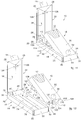
- Figs. 37 - 40 are used to describe a packet according to the invention, which can be combined with all the forms of embodiment described here, of a packet 10 that has the tops 28 and edges 30 for example in a sharp angle, in particular square, or at 90°.
- figs. 37 - 40 are used to describe a packet, which can be combined with all the forms of embodiment described here, of a packet 10 in which the internal packaging 16 is disposed fixed in the lid shell 22, that is, it cannot be extracted from the housing seating 26.
- Figs. 37 - 40 are also used to describe a packet which can be combined with all the forms of embodiment described here, of a packet 10 that comprises an external packaging 14 consisting of millboard or rigid cardboard and an internal packaging 16 housed inside the external packaging 14.
- the external packaging 14 is the clam-shell type, formed by a lid shell 22 and a support shell 18, hinged to each other along a hinge 42 to rotate between an open position and a closed position.
- the internal packaging 16 is conformed as a cup to accommodate a group of smoking articles, for example cigarettes wrapped in a wrapper 13.
- the internal packaging 16 is attached to the support shell 18 of the external packaging 14 so that when the lid shell 22 is in the closed position, the internal packaging 16 is enclosed inside the external packaging 14, whereas when the lid shell 22 is in the open position, the internal packaging 16 is freely accessible from the outside.
- the lid shell 22 comprises lateral box-shaped shoulders or lateral strengthening ribs 351, which abut against corresponding lateral box-shaped shoulders or lateral strengthening ribs 341 of the support shell 18, when the lid shell 22 is in the closed position, and the internal packaging 16 is disposed between the lateral box-shaped shoulders 341 of the support shell 18.
- the internal packaging 16 has a parallelepiped shape, with a bottom or lower wall 85 disposed in correspondence with a lower wall of the external packaging 14, a front wall 86 provided with a front aperture 94 to facilitate access to the group of cigarettes, a back wall 88 disposed in contact with the support shell 18 of the external packaging 14, and two lateral walls 90, which in the example are put in contact with the lateral box-shaped shoulders 341 of the support shell 18, and also an upper aperture.
- the internal packaging 16 is attached to the support shell 18 of the external packaging 14 by gluing the upper wall 88 of the internal packaging 16 inside the back wall of the external packaging 14.
- the external packaging 14 completely encloses the internal packaging 16 when the lid shell 22 is in the closed position.
- the internal packaging 16 is glued inside the external packaging 14 in the free space between the lateral box-shaped shoulders 341 of the support shell 18.
- the internal packaging 16 therefore occupies an overall volume less than the volume of the external packaging 14.
- the lateral box-shaped shoulders 341 of the support shell 18 occupy a transverse space not occupied by the internal packaging 16.
- the longitudinal extension that is, the height of the internal packaging 16 that accommodates the group of cigarettes, is equal to the height of the support shell 18.
- the internal packaging 16 comprises claws 335 (see fig. 42 for example) that protrude laterally to engage with interference with the lateral box-shaped shoulders 351 of the lid shell 22, so as to keep the lid shell 22 in the closed position.
- the external packaging 14 When the lid shell 22 is in the closed position, the external packaging 14 has a rectangular parallelepiped shape with a front wall 61 and a back wall 54, parallel and opposite each other; an upper wall 46 and a lower wall 58, parallel and opposite each other; two lateral walls, parallel and opposite each other.
- the upper wall 46 and the front wall 61 of the external packaging 14 entirely belong to the lid shell 22, whereas the back wall 54 of the external packaging 14 entirely belongs to the support shell 18.
- Each of the two lateral walls 56 of the external packaging 14 belongs partly to the lid shell 22 and partly to the support shell 18, just as the lower wall 58 of the external packaging 14 belongs partly to the lid shell 22 and partly to the support shell 18.
- the lateral walls 56 of the external packaging 14 comprise the lateral box-shaped shoulders 341, 351.
- the hinging line that defines the hinge 42 lies at the edge between the upper wall 46 of the external packaging 14 and the back wall 54 of the external packaging 14.
- the front 61 and back 54 walls are bigger than the lateral walls 56 and the latter are bigger than the lower 56 and upper 46 walls.
- the lateral box-shaped shoulders 351 of the lid shell 22 and the lateral box-shaped shoulders 341 of the support shell 18 are made by folding the respective lateral wall so as to form an abutment surface 356, 346 having a predetermined thickness.
- the abutment surfaces 356 of the lateral box-shaped shoulders 351 of the lid shell 22 develop parallel to the front wall 61 of the external packaging 14 and the abutment surfaces 346 of the lateral box-shaped shoulders 341 of the support shell 18 develop parallel to the back wall 54 of the external packaging 14.
- the lateral box-shaped shoulders 351 of the lid shell 22 and the lateral box-shaped shoulders 341 of the support shell 18 occupy a predetermined space, creating a respective cavity 359, 349.
- each of these ribs is formed by U-shaped cardboard, thus creating the cavities 359, 349 inside.
- the lower wall 58 of the external packaging 14 comprises fins 329 folded against a respective flank of the lateral box-shaped shoulders 351, 341 (see fig. 41 for example).
- the internal packaging 16 is formed by folding an internal blank 300 of the type shown in fig. 44 , for example made of cardboard.
- the internal blank 300 has a first central panel 302 intended to form the front wall 86 of the internal packaging 16 and a second central panel 303 intended to form the back wall 88 of the internal packaging 16. At the sides of the first central panel 302 and the second central panel 303 two respective lateral panels 304, 304' are disposed, intended to form the lateral walls 90 of the internal packaging 16. Each lateral wall 90 of the internal packaging 16 is formed by gluing a respective lateral panel 304 located at the side of the first central panel 302 above the lateral panel 304' located at the side of the second central panel 303.
- transverse panel 301 is disposed, intended to form the lower wall 85 of the internal packaging 16.
- two fins 301' are put, which, folded by 180°, position themselves on the lower wall 85, inside and on the bottom of the internal packaging 16.
- the first central panel 302 of the internal blank 300 has at the upper end the access aperture 94, with a U-shaped profile.
- an extended notch is made for about 10 mm and such as to create the two claws 335 which protrude laterally to engage with interference with the lateral box-shaped shoulders 351 of the lid shell 22, when the lid shell 22 is in the closed position.
- the claws 335 project perpendicularly with respect to the lateral walls 90 of the internal packaging 16.
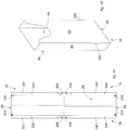
- the external packaging 14 is formed by folding an external blank 250 of the type shown in fig. 43 , made of cardboard for example.
- the external blank 250 comprises a first main panel 222, intended to form the front wall 61 of the external packaging 14, and a second main panel 223, intended to form the back wall 54 of the external packaging 14.
- a transverse central panel 226 is interposed, intended to form the upper wall 46 of the external packaging 14.
- two lateral fins 226' are disposed which, folded at 180°, are glued to the transverse central panel 226 so as to be disposed in the internal part of the upper wall 46 of the external packaging 14.
- first main panel 222 At the two sides of the first main panel 222 three longitudinal lateral panels are disposed in succession, divided by pre-creasing lines and intended to form the lateral box-shaped shoulders 351 of the lid shell 22.
- first main panel 222 we find in succession on both flanks: a first lateral panel 254, intended to form part of the lateral wall 56 of the external packaging 14, a second lateral panel 256, intended to form the abutment surface 356 of the lid shell 22, and a third lateral panel 257, intended to be positioned parallel to the lateral wall 56 of the external packaging 14.
- the first lateral panel 254 is divided from the first main panel 222 by a first pre-creasing line 360; the second lateral panel 256 is divided from the first lateral panel 254 by a second pre-creasing line 361; the third lateral panel is divided from the second lateral panel 256 by a third pre-creasing line 362.
- the widths of the first lateral panel 254 and the third lateral panel 257 are identical.
- transverse panel 258 intended to form part of the lower wall 58 of the external packaging 14.
- transverse panel 258' which, folded at 180°, is glued to the transverse panel 258 below, so as to be disposed in the internal part of the lower wall 58 of the external packaging 14.
- two lateral fins 257' are disposed, which folded at 90° are glued to the third lateral panel 257 so as to improve the stability of the part of the lower wall 58 of the external packaging 14 belonging to the lid shell 22.
- first lateral panel 244 intended to form part of the lateral wall 56 of the external packaging 14
- second lateral panel 246 intended to form the abutment surface 346 of the support shell 18
- third lateral panel 247 intended to be positioned parallel to the lateral wall 56 of the external packaging 14.
- the first lateral panel 244 is divided from the first main panel 222 by a first pre-creasing line 370; the second lateral panel 246 is divided from the first lateral panel 244 by a second pre-creasing line 371; the third lateral panel 247 is divided from the second lateral panel 246 by a third pre-creasing line 372.
- the widths of the first lateral panel 244 and the third lateral panel 247 are identical.
- the internal packaging 16 will then be glued inside the external packaging 14 by gluing the back wall 88 of the internal packaging 16 on the end panels 223'.
- transverse panel 248 intended to form part of the lower wall 58 of the external packaging 14.
- transverse panel 248' which, folded at 180°, is glued to the transverse panel 248 above, so as to be disposed in the internal part of the lower wall 58 of the external packaging 14.
- two lateral fins 247' are disposed, which folded at 90° are glued to the third lateral panel 247 so as to improve the stability of the part of the lower wall 58 of the external packaging 14.
- the widths of the first and third lateral panel 254, 257 intended to form part of the lateral box-shaped shoulder 351 of the lid shell 22 are different, in the example smaller, than the width of the first and third lateral panel 244, 247 intended to form part of the lateral box-shaped shoulder 341 of the support shell 18; while the width of the second lateral panel 256 intended to form the abutment surface 356 of the lid shell 22 and the width of the second lateral panel 246 intended to form the abutment surface 346 of the support shell 18 are identical.
- a fissure 355 is made, to allow the claws 335 to be inserted inside the cavity 359 of the lateral box-shaped shoulder 351 of the lid shell 22.
- the rigid packet with hinged lid for smoking articles according to the present invention allows to satisfy the requirements and overcome the disadvantages of the state of the art.
- the packet for smoking articles according to the present invention guarantees adequate stability for the internal container which houses a group of cigarettes having an overall volume less than the external container.
- the external container can easily be made starting from a single blank of rigid cardboard weighing less than that usually used in this field, while still preserving an adequate overall robustness thanks to the presence of the lateral box-shaped shoulders or lateral strengthening ribs.
- the packet described using figs. 37 - 40 provide a rigid packet 10 for smoking articles comprising an external packaging 14 of the clam-shell type formed by a lid shell 22 and a support shell 18 hinged to each other along a hinge 42 to rotate between an open position and a closed position, an internal packaging 16 conformed as a cup to accommodate a group of smoking articles, said internal packaging 16 being attached to the support shell 18 of the external packaging 14 so that when the lid shell 22 is in the closed position, the internal packaging 16 is enclosed inside the external packaging 14, whereas when the lid shell 22 is in the open position, the internal packaging 16 is freely accessible from the outside.
- the lid shell 22 comprises lateral box-shaped shoulders 351, which abut against corresponding lateral box-shaped shoulders 341 of the support shell 18, when the lid shell 22 is in the closed position, the internal packaging 16 being disposed between the lateral box-shaped shoulders 341 of the support shell 18.
- the internal packaging 16 has a parallelepiped shape, with a bottom or lower wall 85 disposed in correspondence with a lower wall 58 of the external packaging 14.
- the external packaging 14 completely encloses the internal packaging 16 when the lid shell 22 is in the closed position.
- the internal packaging 16 has a front wall 86 provided with an aperture 94 to facilitate access to the group of cigarettes.
- the external packaging 14 is made starting from a single blank.
- the internal packaging 16 comprises claws 335 that protrude laterally to engage with interference with the lateral box-shaped shoulders 351 of the lid shell 22 so as to keep the lid shell 22 in the closed position.
- the internal packaging 16 has lateral walls 90 located in proximity with the lateral box-shaped shoulders 341 of the support shell 18.
- the external packaging 14 is parallelepiped shaped and has a front wall 61, a back wall 54, two lateral walls 56 and an upper wall 46.
- the upper wall 46 belongs entirely to the lid shell 22 and the back wall belongs entirely to the support shell 18.
- the lateral walls 56 of the external packaging 14 comprise the lateral box-shaped shoulders 341, 351.
- the lateral box-shaped shoulders 351 of the lid shell 22 and the lateral box-shaped shoulders 341 of the support shell 18 have respective abutment surfaces 356, 346 that come into contact when the lid shell 22 is in the closed position.
- the abutment surfaces 356 of the lateral box-shaped shoulders 351 of the lid shell 22 develop parallel to the front wall 61 of the external packaging 14 and the abutment surfaces 346 of the lateral box-shaped shoulders 341 of the support shell 18 develop parallel to the back wall 54 of the external packaging 14.
- the lateral box-shaped shoulders 351 of the lid shell 22 and the lateral box-shaped shoulders 341 of the support shell 18 occupy a predetermined space, creating a respective cavity 359, 349.
- the lower wall 58 of the external packaging 14 comprises a pair of fins 329 folded back against the lateral box-shaped shoulders 341, 351.
- a packet 10 according to figs. 37 - 40 can be advantageous in the case of a group of cigarettes that occupies a smaller volume than the overall bulk of the external container.
- a packet is made which contains a group of cigarettes that in its entirety occupies a limited space compared with the volume of the external container, an empty space remains, with the risk that the group of cigarettes can move freely inside the container, and consequently that the structure of the cigarettes themselves might rapidly deteriorate, caused by this free movement.
- the packet 10 according to the present description allows to guarantee in any case the stability of the group of cigarettes, even when there is a space made available by the external container greater than that which can be occupied by the group of cigarettes contained therein.
- the packet 10 stably contains a group of cigarettes, which group of smoking articles, in particular cigarettes, occupies overall a smaller volume compared with the overall volume of the external container in which they are housed, guaranteeing an adequate rigidity of the packet; and at the same time the packet 10 offers spaces that can be used for advertising slogans or other, in the framework of a simple and rational construction solution.
Landscapes
- Engineering & Computer Science (AREA)
- Mechanical Engineering (AREA)
- Packaging Of Annular Or Rod-Shaped Articles, Wearing Apparel, Cassettes, Or The Like (AREA)
- Cartons (AREA)
Priority Applications (1)
| Application Number | Priority Date | Filing Date | Title |
|---|---|---|---|
| PL15742109T PL3172148T3 (pl) | 2014-07-24 | 2015-07-15 | Opakowanie na wyroby do palenia |
Applications Claiming Priority (3)
| Application Number | Priority Date | Filing Date | Title |
|---|---|---|---|
| ITBO20140421 | 2014-07-24 | ||
| ITMI20141932 | 2014-11-10 | ||
| PCT/IB2015/055351 WO2016012907A1 (en) | 2014-07-24 | 2015-07-15 | Packet for smoking articles |
Publications (2)
| Publication Number | Publication Date |
|---|---|
| EP3172148A1 EP3172148A1 (en) | 2017-05-31 |
| EP3172148B1 true EP3172148B1 (en) | 2018-12-19 |
Family
ID=53724408
Family Applications (1)
| Application Number | Title | Priority Date | Filing Date |
|---|---|---|---|
| EP15742109.0A Active EP3172148B1 (en) | 2014-07-24 | 2015-07-15 | Packet for smoking articles |
Country Status (5)
| Country | Link |
|---|---|
| EP (1) | EP3172148B1 (pl) |
| CN (1) | CN106660658B (pl) |
| PL (1) | PL3172148T3 (pl) |
| RU (1) | RU2682187C2 (pl) |
| WO (1) | WO2016012907A1 (pl) |
Families Citing this family (3)
| Publication number | Priority date | Publication date | Assignee | Title |
|---|---|---|---|---|
| CN107738836B (zh) * | 2017-11-14 | 2023-09-15 | 常德金德新材料科技股份有限公司 | 一种烟盒 |
| DE102018002742A1 (de) | 2018-04-03 | 2019-10-10 | Focke & Co. (Gmbh & Co. Kg) | Packung für Produkte der Zigarettenindustrie und Verfahren zur Herstellung derselben |
| WO2019226856A1 (en) * | 2018-05-23 | 2019-11-28 | Diamond Packaging | Locking folding carton |
Family Cites Families (7)
| Publication number | Priority date | Publication date | Assignee | Title |
|---|---|---|---|---|
| GB780912A (en) * | 1955-05-16 | 1957-08-07 | Ets Nuyts Freres | Improvements in and relating to cardboard boxes |
| ITBO20030451A1 (it) * | 2003-07-29 | 2005-01-30 | Gd Spa | Contenitore e semilavorato pieghevole per la realizzazione del contenitore stesso. |
| CN2811172Y (zh) * | 2005-07-22 | 2006-08-30 | 白雪生 | 侧翻式圆角烟盒 |
| RU2448881C1 (ru) * | 2008-02-25 | 2012-04-27 | Джапан Тобакко Инк. | Пачка с поворотной крышкой |
| ITBO20080411A1 (it) * | 2008-06-27 | 2009-12-28 | Gd Spa | Pacchetto per articoli di forma allungata. |
| DE102010019233A1 (de) * | 2010-05-03 | 2011-11-03 | Focke & Co. (Gmbh & Co. Kg) | Kappenschachtel für Zigaretten sowie Verfahren und Vorrichtung zum Herstellen |
| DE102010035938B4 (de) * | 2010-08-31 | 2022-02-10 | British American Tobacco (Germany) Gmbh | Zigarettenpackung mit Hohlraum |
-
2015
- 2015-07-15 PL PL15742109T patent/PL3172148T3/pl unknown
- 2015-07-15 WO PCT/IB2015/055351 patent/WO2016012907A1/en not_active Ceased
- 2015-07-15 RU RU2017103770A patent/RU2682187C2/ru active
- 2015-07-15 EP EP15742109.0A patent/EP3172148B1/en active Active
- 2015-07-15 CN CN201580041083.1A patent/CN106660658B/zh active Active
Non-Patent Citations (1)
| Title |
|---|
| None * |
Also Published As
| Publication number | Publication date |
|---|---|
| RU2017103770A (ru) | 2018-08-27 |
| WO2016012907A1 (en) | 2016-01-28 |
| CN106660658A (zh) | 2017-05-10 |
| PL3172148T3 (pl) | 2019-06-28 |
| RU2017103770A3 (pl) | 2018-09-11 |
| EP3172148A1 (en) | 2017-05-31 |
| RU2682187C2 (ru) | 2019-03-15 |
| CN106660658B (zh) | 2019-09-10 |
Similar Documents
| Publication | Publication Date | Title |
|---|---|---|
| CN102811913B (zh) | 滑动件和壳体式容器、其薄板坯件及形成方法 | |
| EP2094586B1 (en) | Package of tobacco articles | |
| EP1931570B1 (en) | Rigid, slide-open package for tobacco articles | |
| EP3227195B1 (en) | Rigid packet with hinged lid and containing a group of smoking articles of reduced size | |
| KR20110030405A (ko) | 슬라이드하여 여는 담배갑 및 관련 제조 방법 | |
| US10214342B2 (en) | Dispenser box for fragile items, including tubes for cigarettes | |
| EP2459467A1 (en) | Container comprising smoking articles with a lifting element | |
| EP3105148B1 (en) | Packet for smoking articles | |
| EP1725460B1 (en) | Rigid package of tobacco articles | |
| JP2018537367A (ja) | 摺動内側フレームを備えた消費財のための容器 | |
| JP2008525279A (ja) | 煙草製品のためのパケット | |
| CN101754902B (zh) | 具有整体式连接器的双包装 | |
| EP3172148B1 (en) | Packet for smoking articles | |
| EP3194282B1 (en) | Pack for tobacco industry products | |
| EP2456688B1 (en) | Packet for smoke articles | |
| EP3079997B1 (en) | Packaging for smoking articles | |
| EP3237304B1 (en) | Container having an inner frame with a spaced back wall, corresponding inner frame and reel | |
| JP5068267B2 (ja) | 喫煙物品の段状ヒンジ蓋パック | |
| JP4729037B2 (ja) | タバコ製品の強固なヒンジ式フタ付きパッケージ | |
| EP2817232B1 (en) | Rigid packet of cigarettes | |
| EP3240739B1 (en) | Container for consumer goods having opening and closing mechanism | |
| EP3166859B1 (en) | Rigid packet of cigarettes and respective blank | |
| CN104159835B (zh) | 用于烟草制品的包装盒 | |
| EP3227196B1 (en) | Rigid packet with hinged lid and containing a group of smoking articles of reduced size | |
| JP4507261B2 (ja) | 紙カートン |
Legal Events
| Date | Code | Title | Description |
|---|---|---|---|
| STAA | Information on the status of an ep patent application or granted ep patent |
Free format text: STATUS: THE INTERNATIONAL PUBLICATION HAS BEEN MADE |
|
| PUAI | Public reference made under article 153(3) epc to a published international application that has entered the european phase |
Free format text: ORIGINAL CODE: 0009012 |
|
| STAA | Information on the status of an ep patent application or granted ep patent |
Free format text: STATUS: REQUEST FOR EXAMINATION WAS MADE |
|
| 17P | Request for examination filed |
Effective date: 20170127 |
|
| AK | Designated contracting states |
Kind code of ref document: A1 Designated state(s): AL AT BE BG CH CY CZ DE DK EE ES FI FR GB GR HR HU IE IS IT LI LT LU LV MC MK MT NL NO PL PT RO RS SE SI SK SM TR |
|
| AX | Request for extension of the european patent |
Extension state: BA ME |
|
| DAV | Request for validation of the european patent (deleted) | ||
| DAX | Request for extension of the european patent (deleted) | ||
| STAA | Information on the status of an ep patent application or granted ep patent |
Free format text: STATUS: EXAMINATION IS IN PROGRESS |
|
| 17Q | First examination report despatched |
Effective date: 20171214 |
|
| GRAP | Despatch of communication of intention to grant a patent |
Free format text: ORIGINAL CODE: EPIDOSNIGR1 |
|
| STAA | Information on the status of an ep patent application or granted ep patent |
Free format text: STATUS: GRANT OF PATENT IS INTENDED |
|
| INTG | Intention to grant announced |
Effective date: 20180704 |
|
| GRAS | Grant fee paid |
Free format text: ORIGINAL CODE: EPIDOSNIGR3 |
|
| GRAA | (expected) grant |
Free format text: ORIGINAL CODE: 0009210 |
|
| STAA | Information on the status of an ep patent application or granted ep patent |
Free format text: STATUS: THE PATENT HAS BEEN GRANTED |
|
| AK | Designated contracting states |
Kind code of ref document: B1 Designated state(s): AL AT BE BG CH CY CZ DE DK EE ES FI FR GB GR HR HU IE IS IT LI LT LU LV MC MK MT NL NO PL PT RO RS SE SI SK SM TR |
|
| REG | Reference to a national code |
Ref country code: GB Ref legal event code: FG4D |
|
| REG | Reference to a national code |
Ref country code: CH Ref legal event code: EP |
|
| REG | Reference to a national code |
Ref country code: IE Ref legal event code: FG4D |
|
| REG | Reference to a national code |
Ref country code: DE Ref legal event code: R096 Ref document number: 602015021902 Country of ref document: DE |
|
| REG | Reference to a national code |
Ref country code: AT Ref legal event code: REF Ref document number: 1078452 Country of ref document: AT Kind code of ref document: T Effective date: 20190115 |
|
| REG | Reference to a national code |
Ref country code: NL Ref legal event code: MP Effective date: 20181219 |
|
| PG25 | Lapsed in a contracting state [announced via postgrant information from national office to epo] |
Ref country code: HR Free format text: LAPSE BECAUSE OF FAILURE TO SUBMIT A TRANSLATION OF THE DESCRIPTION OR TO PAY THE FEE WITHIN THE PRESCRIBED TIME-LIMIT Effective date: 20181219 Ref country code: LV Free format text: LAPSE BECAUSE OF FAILURE TO SUBMIT A TRANSLATION OF THE DESCRIPTION OR TO PAY THE FEE WITHIN THE PRESCRIBED TIME-LIMIT Effective date: 20181219 Ref country code: FI Free format text: LAPSE BECAUSE OF FAILURE TO SUBMIT A TRANSLATION OF THE DESCRIPTION OR TO PAY THE FEE WITHIN THE PRESCRIBED TIME-LIMIT Effective date: 20181219 Ref country code: BG Free format text: LAPSE BECAUSE OF FAILURE TO SUBMIT A TRANSLATION OF THE DESCRIPTION OR TO PAY THE FEE WITHIN THE PRESCRIBED TIME-LIMIT Effective date: 20190319 Ref country code: LT Free format text: LAPSE BECAUSE OF FAILURE TO SUBMIT A TRANSLATION OF THE DESCRIPTION OR TO PAY THE FEE WITHIN THE PRESCRIBED TIME-LIMIT Effective date: 20181219 Ref country code: NO Free format text: LAPSE BECAUSE OF FAILURE TO SUBMIT A TRANSLATION OF THE DESCRIPTION OR TO PAY THE FEE WITHIN THE PRESCRIBED TIME-LIMIT Effective date: 20190319 |
|
| REG | Reference to a national code |
Ref country code: LT Ref legal event code: MG4D |
|
| REG | Reference to a national code |
Ref country code: AT Ref legal event code: MK05 Ref document number: 1078452 Country of ref document: AT Kind code of ref document: T Effective date: 20181219 |
|
| PG25 | Lapsed in a contracting state [announced via postgrant information from national office to epo] |
Ref country code: RS Free format text: LAPSE BECAUSE OF FAILURE TO SUBMIT A TRANSLATION OF THE DESCRIPTION OR TO PAY THE FEE WITHIN THE PRESCRIBED TIME-LIMIT Effective date: 20181219 Ref country code: GR Free format text: LAPSE BECAUSE OF FAILURE TO SUBMIT A TRANSLATION OF THE DESCRIPTION OR TO PAY THE FEE WITHIN THE PRESCRIBED TIME-LIMIT Effective date: 20190320 Ref country code: AL Free format text: LAPSE BECAUSE OF FAILURE TO SUBMIT A TRANSLATION OF THE DESCRIPTION OR TO PAY THE FEE WITHIN THE PRESCRIBED TIME-LIMIT Effective date: 20181219 Ref country code: SE Free format text: LAPSE BECAUSE OF FAILURE TO SUBMIT A TRANSLATION OF THE DESCRIPTION OR TO PAY THE FEE WITHIN THE PRESCRIBED TIME-LIMIT Effective date: 20181219 |
|
| PG25 | Lapsed in a contracting state [announced via postgrant information from national office to epo] |
Ref country code: NL Free format text: LAPSE BECAUSE OF FAILURE TO SUBMIT A TRANSLATION OF THE DESCRIPTION OR TO PAY THE FEE WITHIN THE PRESCRIBED TIME-LIMIT Effective date: 20181219 |
|
| PG25 | Lapsed in a contracting state [announced via postgrant information from national office to epo] |
Ref country code: ES Free format text: LAPSE BECAUSE OF FAILURE TO SUBMIT A TRANSLATION OF THE DESCRIPTION OR TO PAY THE FEE WITHIN THE PRESCRIBED TIME-LIMIT Effective date: 20181219 Ref country code: CZ Free format text: LAPSE BECAUSE OF FAILURE TO SUBMIT A TRANSLATION OF THE DESCRIPTION OR TO PAY THE FEE WITHIN THE PRESCRIBED TIME-LIMIT Effective date: 20181219 Ref country code: PT Free format text: LAPSE BECAUSE OF FAILURE TO SUBMIT A TRANSLATION OF THE DESCRIPTION OR TO PAY THE FEE WITHIN THE PRESCRIBED TIME-LIMIT Effective date: 20190419 |
|
| PG25 | Lapsed in a contracting state [announced via postgrant information from national office to epo] |
Ref country code: RO Free format text: LAPSE BECAUSE OF FAILURE TO SUBMIT A TRANSLATION OF THE DESCRIPTION OR TO PAY THE FEE WITHIN THE PRESCRIBED TIME-LIMIT Effective date: 20181219 Ref country code: SK Free format text: LAPSE BECAUSE OF FAILURE TO SUBMIT A TRANSLATION OF THE DESCRIPTION OR TO PAY THE FEE WITHIN THE PRESCRIBED TIME-LIMIT Effective date: 20181219 Ref country code: SM Free format text: LAPSE BECAUSE OF FAILURE TO SUBMIT A TRANSLATION OF THE DESCRIPTION OR TO PAY THE FEE WITHIN THE PRESCRIBED TIME-LIMIT Effective date: 20181219 Ref country code: EE Free format text: LAPSE BECAUSE OF FAILURE TO SUBMIT A TRANSLATION OF THE DESCRIPTION OR TO PAY THE FEE WITHIN THE PRESCRIBED TIME-LIMIT Effective date: 20181219 Ref country code: IS Free format text: LAPSE BECAUSE OF FAILURE TO SUBMIT A TRANSLATION OF THE DESCRIPTION OR TO PAY THE FEE WITHIN THE PRESCRIBED TIME-LIMIT Effective date: 20190419 |
|
| REG | Reference to a national code |
Ref country code: DE Ref legal event code: R097 Ref document number: 602015021902 Country of ref document: DE |
|
| PLBE | No opposition filed within time limit |
Free format text: ORIGINAL CODE: 0009261 |
|
| STAA | Information on the status of an ep patent application or granted ep patent |
Free format text: STATUS: NO OPPOSITION FILED WITHIN TIME LIMIT |
|
| PG25 | Lapsed in a contracting state [announced via postgrant information from national office to epo] |
Ref country code: DK Free format text: LAPSE BECAUSE OF FAILURE TO SUBMIT A TRANSLATION OF THE DESCRIPTION OR TO PAY THE FEE WITHIN THE PRESCRIBED TIME-LIMIT Effective date: 20181219 Ref country code: AT Free format text: LAPSE BECAUSE OF FAILURE TO SUBMIT A TRANSLATION OF THE DESCRIPTION OR TO PAY THE FEE WITHIN THE PRESCRIBED TIME-LIMIT Effective date: 20181219 |
|
| 26N | No opposition filed |
Effective date: 20190920 |
|
| PG25 | Lapsed in a contracting state [announced via postgrant information from national office to epo] |
Ref country code: SI Free format text: LAPSE BECAUSE OF FAILURE TO SUBMIT A TRANSLATION OF THE DESCRIPTION OR TO PAY THE FEE WITHIN THE PRESCRIBED TIME-LIMIT Effective date: 20181219 Ref country code: MC Free format text: LAPSE BECAUSE OF FAILURE TO SUBMIT A TRANSLATION OF THE DESCRIPTION OR TO PAY THE FEE WITHIN THE PRESCRIBED TIME-LIMIT Effective date: 20181219 |
|
| REG | Reference to a national code |
Ref country code: CH Ref legal event code: PL |
|
| GBPC | Gb: european patent ceased through non-payment of renewal fee |
Effective date: 20190715 |
|
| PG25 | Lapsed in a contracting state [announced via postgrant information from national office to epo] |
Ref country code: TR Free format text: LAPSE BECAUSE OF FAILURE TO SUBMIT A TRANSLATION OF THE DESCRIPTION OR TO PAY THE FEE WITHIN THE PRESCRIBED TIME-LIMIT Effective date: 20181219 |
|
| REG | Reference to a national code |
Ref country code: BE Ref legal event code: MM Effective date: 20190731 |
|
| PG25 | Lapsed in a contracting state [announced via postgrant information from national office to epo] |
Ref country code: GB Free format text: LAPSE BECAUSE OF NON-PAYMENT OF DUE FEES Effective date: 20190715 |
|
| PG25 | Lapsed in a contracting state [announced via postgrant information from national office to epo] |
Ref country code: LI Free format text: LAPSE BECAUSE OF NON-PAYMENT OF DUE FEES Effective date: 20190731 Ref country code: LU Free format text: LAPSE BECAUSE OF NON-PAYMENT OF DUE FEES Effective date: 20190715 Ref country code: BE Free format text: LAPSE BECAUSE OF NON-PAYMENT OF DUE FEES Effective date: 20190731 Ref country code: CH Free format text: LAPSE BECAUSE OF NON-PAYMENT OF DUE FEES Effective date: 20190731 |
|
| PG25 | Lapsed in a contracting state [announced via postgrant information from national office to epo] |
Ref country code: FR Free format text: LAPSE BECAUSE OF NON-PAYMENT OF DUE FEES Effective date: 20190731 |
|
| PG25 | Lapsed in a contracting state [announced via postgrant information from national office to epo] |
Ref country code: IE Free format text: LAPSE BECAUSE OF NON-PAYMENT OF DUE FEES Effective date: 20190715 |
|
| PG25 | Lapsed in a contracting state [announced via postgrant information from national office to epo] |
Ref country code: CY Free format text: LAPSE BECAUSE OF FAILURE TO SUBMIT A TRANSLATION OF THE DESCRIPTION OR TO PAY THE FEE WITHIN THE PRESCRIBED TIME-LIMIT Effective date: 20181219 |
|
| PG25 | Lapsed in a contracting state [announced via postgrant information from national office to epo] |
Ref country code: HU Free format text: LAPSE BECAUSE OF FAILURE TO SUBMIT A TRANSLATION OF THE DESCRIPTION OR TO PAY THE FEE WITHIN THE PRESCRIBED TIME-LIMIT; INVALID AB INITIO Effective date: 20150715 Ref country code: MT Free format text: LAPSE BECAUSE OF FAILURE TO SUBMIT A TRANSLATION OF THE DESCRIPTION OR TO PAY THE FEE WITHIN THE PRESCRIBED TIME-LIMIT Effective date: 20181219 |
|
| PG25 | Lapsed in a contracting state [announced via postgrant information from national office to epo] |
Ref country code: MK Free format text: LAPSE BECAUSE OF FAILURE TO SUBMIT A TRANSLATION OF THE DESCRIPTION OR TO PAY THE FEE WITHIN THE PRESCRIBED TIME-LIMIT Effective date: 20181219 |
|
| P01 | Opt-out of the competence of the unified patent court (upc) registered |
Effective date: 20230508 |
|
| PGFP | Annual fee paid to national office [announced via postgrant information from national office to epo] |
Ref country code: PL Payment date: 20250610 Year of fee payment: 11 |
|
| PGFP | Annual fee paid to national office [announced via postgrant information from national office to epo] |
Ref country code: DE Payment date: 20250723 Year of fee payment: 11 |
|
| PGFP | Annual fee paid to national office [announced via postgrant information from national office to epo] |
Ref country code: IT Payment date: 20250722 Year of fee payment: 11 |