EP3172133B1 - Vorrichtung und verfahren zur herstellung von packungen für rauchartikel - Google Patents
Vorrichtung und verfahren zur herstellung von packungen für rauchartikel Download PDFInfo
- Publication number
- EP3172133B1 EP3172133B1 EP15741361.8A EP15741361A EP3172133B1 EP 3172133 B1 EP3172133 B1 EP 3172133B1 EP 15741361 A EP15741361 A EP 15741361A EP 3172133 B1 EP3172133 B1 EP 3172133B1
- Authority
- EP
- European Patent Office
- Prior art keywords
- packet
- packets
- station
- transfer wheel
- wheel
- Prior art date
- Legal status (The legal status is an assumption and is not a legal conclusion. Google has not performed a legal analysis and makes no representation as to the accuracy of the status listed.)
- Active
Links
Images



Classifications
-
- B—PERFORMING OPERATIONS; TRANSPORTING
- B65—CONVEYING; PACKING; STORING; HANDLING THIN OR FILAMENTARY MATERIAL
- B65B—MACHINES, APPARATUS OR DEVICES FOR, OR METHODS OF, PACKAGING ARTICLES OR MATERIALS; UNPACKING
- B65B51/00—Devices for, or methods of, sealing or securing package folds or closures; Devices for gathering or twisting wrappers, or necks of bags
- B65B51/02—Applying adhesives or sealing liquids
- B65B51/023—Applying adhesives or sealing liquids using applicator nozzles
-
- B—PERFORMING OPERATIONS; TRANSPORTING
- B65—CONVEYING; PACKING; STORING; HANDLING THIN OR FILAMENTARY MATERIAL
- B65B—MACHINES, APPARATUS OR DEVICES FOR, OR METHODS OF, PACKAGING ARTICLES OR MATERIALS; UNPACKING
- B65B19/00—Packaging rod-shaped or tubular articles susceptible to damage by abrasion or pressure, e.g. cigarettes, cigars, macaroni, spaghetti, drinking straws or welding electrodes
- B65B19/02—Packaging cigarettes
- B65B19/12—Inserting the cigarettes, or wrapped groups thereof, into preformed containers
- B65B19/14—Inserting the cigarettes, or wrapped groups thereof, into preformed containers into pocket boxes, e.g. boxes of rectangular form closed at one end by a flap adapted to be inserted into a slot in the body
-
- B—PERFORMING OPERATIONS; TRANSPORTING
- B65—CONVEYING; PACKING; STORING; HANDLING THIN OR FILAMENTARY MATERIAL
- B65B—MACHINES, APPARATUS OR DEVICES FOR, OR METHODS OF, PACKAGING ARTICLES OR MATERIALS; UNPACKING
- B65B19/00—Packaging rod-shaped or tubular articles susceptible to damage by abrasion or pressure, e.g. cigarettes, cigars, macaroni, spaghetti, drinking straws or welding electrodes
- B65B19/02—Packaging cigarettes
- B65B19/22—Wrapping the cigarettes; Packaging the cigarettes in containers formed by folding wrapping material around formers
- B65B19/223—Wrapping the cigarettes; Packaging the cigarettes in containers formed by folding wrapping material around formers in a curved path; in a combination of straight and curved paths, e.g. on rotary tables or other endless conveyors
-
- B—PERFORMING OPERATIONS; TRANSPORTING
- B65—CONVEYING; PACKING; STORING; HANDLING THIN OR FILAMENTARY MATERIAL
- B65B—MACHINES, APPARATUS OR DEVICES FOR, OR METHODS OF, PACKAGING ARTICLES OR MATERIALS; UNPACKING
- B65B49/00—Devices for folding or bending wrappers around contents
- B65B49/02—Fixed or resiliently-mounted folders, e.g. non-driven rollers
-
- B—PERFORMING OPERATIONS; TRANSPORTING
- B65—CONVEYING; PACKING; STORING; HANDLING THIN OR FILAMENTARY MATERIAL
- B65B—MACHINES, APPARATUS OR DEVICES FOR, OR METHODS OF, PACKAGING ARTICLES OR MATERIALS; UNPACKING
- B65B49/00—Devices for folding or bending wrappers around contents
- B65B49/08—Reciprocating or oscillating folders
-
- B—PERFORMING OPERATIONS; TRANSPORTING
- B65—CONVEYING; PACKING; STORING; HANDLING THIN OR FILAMENTARY MATERIAL
- B65B—MACHINES, APPARATUS OR DEVICES FOR, OR METHODS OF, PACKAGING ARTICLES OR MATERIALS; UNPACKING
- B65B61/00—Auxiliary devices, not otherwise provided for, for operating on sheets, blanks, webs, binding material, containers or packages
- B65B61/24—Auxiliary devices, not otherwise provided for, for operating on sheets, blanks, webs, binding material, containers or packages for shaping or reshaping completed packages
Definitions
- Forms of embodiment described here concern an apparatus and method for making up packets for smoking articles, such as for example, but not exclusively, cigarettes.
- the exit wheel can rotate around an axis of rotation to move a plurality of gripping heads along a predefined path between the entrance station and the exit station.
- Each gripping head is provided to receive a respective packet of cigarettes having a longitudinal axis and smaller longitudinal walls, each of which defined by a corresponding external longitudinal tongue or lateral wing, and by an internal longitudinal tongue.
- the exit wheel receives each packet at the entrance station with the corresponding external longitudinal tongues or lateral wings in the open position, that is, raised and inclined: the external longitudinal tongues must be glued to the internal longitudinal tongues to achieve at least one step of making up the packet.
- each gripping head includes folding elements to fold, at the entrance station and at the moment the packet is inserted into the corresponding gripping head, with the transfer wheel stationary, each of the open lateral wings, in a closed position in contact against the corresponding internal longitudinal tongue.
- the folding elements are also provided to hold the packets, preventing them from falling out of the respective gripping heads during the rotation of the wheel along the predefined path.
- This known apparatus provides that the open lateral wings are suitably folded before the packet is fed through the predefined path and also all the operations to be performed on the lateral wings and/or on the internal longitudinal tongues, in particular gluing, are completed at the entrance station.
- This known apparatus therefore has the disadvantage that it supplies a reduced productivity and needs to position a plurality of operating units at the entrance station, which is already relatively crowded with other operating units.
- Another disadvantage of this known apparatus is the presence, on board the exit wheel, of the folding elements in each gripping head: considering the fact that the exit wheel is in rotational movement and that therefore it takes the gripping heads with it in rotation, this increases the rotational inertia of the exit wheel itself, making it expensive, complex and difficult to drive and control it.
- the packet support and folding means receive the packets with the open wings from the forming wheel and, following the disposition with wings radially toward the outside of the packet in the forming wheel, immediately engage the open wings of the packets, folding them and pressing them until they contact the main body of the packet, in particular by folding the panels backward with respect to the direction of feed, that is, the radial direction of the wheel. Therefore, as the main effect, they support the packets bilaterally through friction and, as a collateral effect, they fold the panels.
- the panels themselves re-open, rotating forward, due to elastic return, when they are no longer stressed by the packet support and folding means, in order to receive the glue; only later are they folded definitively, thanks to the means for opposing the elastic return and the conveyor means.
- This known device can have the disadvantage that the linear transfer means downstream of the forming wheel impart a considerable acceleration for the movement of the packets which could deform them and crush them.
- Document EP-A-1.321.364 is also known, which describes an apparatus for making up packets of cigarettes of the type in question, provided with an exit wheel equipped with gripping heads, each provided with folding elements.
- the external lateral wings are folded on the internal longitudinal tongues by folding elements provided in each gripping head during the rotation of the transfer wheel along the predefined path in an intermediate position downstream of the entrance station and upstream of the exit station.
- This known apparatus also provides a first station for upending the packet by 90°, immediately downstream of the entrance station, and a second station for upending the packet by 90°, immediately upstream of the exit station.
- the known apparatus provides, downstream of the first upending station, a glue distribution station to distribute glue onto the internal longitudinal tongues and a subsequent folding station, upstream of the second upending station, to fold the open lateral wings in contact against the internal longitudinal tongues.
- This known solution also suffers the disadvantage of excessive rotational inertia, deriving from the presence of the folding elements provided in the gripping heads on board the exit wheel in continuous rotation.
- the presence of the folding elements for each gripping head entails high investment costs, difficulties in assembly, need for maintenance and high frequency of repairs and replacements.
- Document GB-A-2.134.870 further discloses a cigarette-packaging machine and a respective method of the known type.
- an apparatus for making up packets for smoking articles.
- the apparatus includes:
- the apparatus includes:
- a method for the making up of packets for smoking articles includes:
- the method includes:
- the apparatus and method according to the present description are not affected by the disadvantage of excessive rotational inertia, nor by problems of assembly, maintenance, repairs, machine stoppages etc., that could derive from the presence of the folding elements provided in each of the gripping heads on board the rotating transfer wheel.
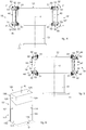
- Figs. 1 , 2 and 3 are used to describe forms of embodiment of an apparatus 10 for making up packets 100 for smoking articles 102 ( fig. 7 ).
- Examples of possible smoking articles are cigarettes, cigars or similar or comparable smoking articles.
- the apparatus 10 includes a packet transfer wheel 12 provided with an entrance station 14 and an exit station 16, between which a predefined transfer path P develops.
- the packet transfer wheel 12 can rotate around an axis of rotation Y ( figs. 4 and 5 ), as indicated by the arrow R in fig. 1 (for example clockwise rotation), in order to move a plurality of packet gripping heads 18 along the predefined transfer path P.
- Forms of embodiment described here therefore provide to move the packets 100 along the transfer path P between the entrance station 14 and the exit station 16 of the packet transfer wheel 12.
- the packet transfer wheel 12 can be advantageous, in that it allows to move packets 100 taken singularly one by one from the packet gripping heads 18, and not packets 100 linearly moved together packed, that would be subjected to a considerable acceleration that could deform and crush them.
- the transfer path P can be a circular path, for example an arc of a circle, that develops between the entrance station 14 and the exit station 16.
- the entrance stations 14 and exit stations 16 can be in diametrically opposite positions on the packet transfer wheel 12.
- the transfer path P can, for example, concern an angular sector of 180° of the packet transfer wheel 12, where an angle of 0° is taken as reference in correspondence to the entrance station 14.
- the entrance station 14 and the exit station 16 are in any other reciprocal angular position, not diametrically opposite on the packet transfer wheel 12 and the transfer path P can, for example, concern a different angular sector, for example less than 180°, for example from 30° to 150°, or greater than 180°, for example from 210° to 330°, or other angular positions, according to needs.
- the axis of rotation Y of the packet transfer wheel 12 can be horizontal, while in other implementations it can be vertical.
- fig. 1 is used to describe forms of embodiment in which the axis of rotation Y of the packet transfer wheel 12 is horizontal and therefore the packet transfer wheel 12 is located vertical.
- the packet transfer wheel 12 can, for example, be made to rotate step-wise, where the rotation steps can be coordinated with the angular sectors affected by specific workings or operations, such as entrance, gluing and exit of the packets 100.
- an actuator can be provided for the rotation of the packet transfer wheel 12.
- the actuator can include a motor that can be an electric motor, in particular an electric step motor, or servomotor, for example provided with a position transducer, such as an encoder, in particular a rotary encoder.
- Each packet gripping head 18 of the packet transfer wheel 12 can be configured to receive and hold a respective packet 100 of smoking articles 102 and transport it in a stable way from the entrance station 14 to the exit station 16, along said transfer path P.
- the packet transfer wheel 12 can be constrained to a support or work plane 11, ( figs. 4 and 5 ).
- the support plane 11 can be provided vertical or horizontal depending on the spatial disposition of the packet transfer wheel 12.
- the packet transfer wheel 12 can be attached to the support plane 11, for example cantilevered, by means of a central support hub 13 (see figs. 4 and 5 ), inside which, for example, actuation, feed, regulation and control components of the packet transfer wheel 12 and/or its components and/or other components operatively associated to the packet transfer wheel 12 can be provided.
- a packaging or forming wheel 20 is provided, upstream of the packet transfer wheel 12, which rotates around an axis of rotation parallel to the axis of rotation Y of the packet transfer wheel 12, as indicated by the arrow R' of rotation of the packaging wheel 20 (for example anti-clockwise rotation).
- the packaging wheel 20 is configured to rotate step-wise, advantageously synchronized with the step-wise rotation of the packet transfer wheel 12.
- the packaging wheel 20 is configured to supply, in the entrance station 14 of the packet transfer wheel 12, a succession of packets 100 for smoking articles 102 to be completed by means of subsequent workings, such as gluing one or more of their components 104, 106.
- the packaging wheel 20 supplies the packets 100 radially to the packet transfer wheel 12 (see for example fig. 1 ). Therefore, a packet gripping head 18 of the packet transfer wheel 12 can receive radially, at the entrance station 14, a packet 100 for smoking articles 102 from the packaging wheel 20 (see for example fig. 1 ).
- the present invention provides that, compared with the state of the art described in WO-A-2010/119472 , the linear transfer means at the exit of the packaging or forming wheel are substituted by the packet transfer wheel 12, with the advantage, as discussed above, of preventing the linear accelerations that risk deforming and crushing the packets, since the structure of the packet transfer wheel 12, which advantageously provides individual seatings in which the packets are housed individually, and the rotatory movement of which keep the packet from deforming.
- a packaging wheel 20 may not be provided upstream and it can be provided that the packet transfer wheel 12 is a wheel configured to also carry out the composition of packets, assembling, in packets ready to be glued and completed in the packaging, the various components that are received from the wheel, such as for example groups of cigarettes already wrapped in an inner wrapping, ribs and external wrappers.
- the entrance station 14 can be defined by any intermediate station of the packet transfer wheel 12 also configured for the composition of packets, at which, on each occasion, the assembled packets are presented, with the open components to be folded, ready to be glued to complete the packaging.
- the apparatus 10 includes a glue distribution station 22 configured to distribute glue to the packets 100 for smoking articles 102 ( fig. 1 ).
- the glue distribution station 22 can be configured to distribute glue along the transfer path P which the packets 100 travel on, transported by the packet gripping heads 18 of the packet transfer wheel 12.
- the glue distribution station 22 is outside the packet transfer wheel 12 and is disposed along the transfer path P.
- the glue distribution station 22 is disposed between the entrance station 14 and the exit station 16, along the transfer path P, for example in a median position.
- Forms of embodiment described here therefore provide to distribute glue, between the entrance station 14 and the exit station 16, to the packets 100 moved along the transfer path P.
- the glue distribution station 22 can be disposed in correspondence with an angle of 90° downward (that is, negative), with respect to the entrance station 14.
- the exit station 16 can be disposed in correspondence with an angle of 180° downward (that is, negative), with respect to the entrance station 14.
- the glue distribution station 22 can be disposed in any other angular position along the transfer path P between the entrance station 14 and the exit station 16, for example in the angular sector between 0° and 90° downward, or in the subsequent angular sector between 90° and 180° downward.
- the glue distribution station 22 can be disposed at 30°, 45°, 60°, 120°, 135°, 150° downward, or in any intermediate angular position between these angular values.
- the glue distribution station 22 can be disposed in correspondence to the entrance station 14.
- the glue distribution station 22 can be disposed in correspondence with the exit station 16.
- the apparatus 10 also includes a packet conveying station 24, disposed downstream of the exit station 16 and outside the packet transfer wheel 12, and therefore outside the transfer path P, along which the packets 100 for smoking articles 102 are conveyed along a conveying path C.
- the packet transfer wheel 12 can supply the packets 100 to the packet conveying station 24 in a radial direction M.
- the packets 100 can be expelled from the exit station 16 in the radial direction M ( figs. 1 , 2 , 3 and 10 ).
- the packet conveying station 24 can be configured to receive the packets 100 for smoking articles 102 exiting from the exit station 16 and on which glue has already been distributed, in order to glue the components 104, 106 of the packet which need this work, suitably folded, and to convey them along said conveying path C.
- a packed feed configuration can be provided for example, along the conveying path C, in which the packets 100 are made to advance in a row one after the other.
- the packets 100 can be moved discretely, that is, separated from each other ( fig. 10 ).
- the conveying path C can be linear, and in particular it can be a linear and radial direction with respect to the packet transfer wheel 12, that is, it can be aligned with the radial direction M of expulsion (see fig. 1 for example), or at least partly circular. In other variants, the conveying path C can be transverse to said radial direction M of expulsion. For example, the conveying path C can be orthogonal to the radial direction M of expulsion ( fig. 10 ), that is, it can be parallel to a direction tangential to the packet transfer wheel 12 in correspondence to the exit station 16.
- the packet conveying station 24 is configured to glue and also consolidate and stabilize, along the conveying path C, the gluing of the packets 100 for smoking articles 102 received from the exit station 16 of the packet transfer wheel 12.
- Forms of embodiment described here therefore provide to glue, consolidate and stabilize the gluing of the packets 100, conveying the packets 100 with components 104 folded and that are kept folded along the packet conveying station 24, downstream of the packet transfer wheel 12.
- the packet conveying station 24 can be configured to keep the components 104, 106 to be glued of each of the packets 100 in contact against each other, in particular for a sufficient time so that gluing can be performed and the glue consolidates and stabilizes, rendering the coupling by gluing stable and definitive.
- the length of the conveying path C and/or the speed of feed of the packets 100 along the conveying path C can be sized to supply a sufficient passage and staying time so that, as well as gluing, there is also consolidation and stabilization of the gluing.
- the packet conveying station 24 can be associated to an entrance mouth 34, which can receive the packets 100 exiting from the exit station 16, in particular once these have been expelled from the gripping heads 18.
- the entrance mouth 34 can be separate from the packet conveying station 24, upstream thereof.
- the packet conveying station 24 can be provided with a conveying channel 25, through which the packets 100 are made to advance to be subjected to the gluing, consolidation and stabilization of the gluing.
- the conveying channel 25 can be provided to obtain the feed in a packed condition of the packets 100.
- the conveying channel 25 can typically be directly downstream of the entrance mouth 34.
- the passage cross section of the conveying channel 25 can essentially coincide, except for construction tolerances, with a transverse size D of the packets 100 that are made to advance along the packet conveying station 24. In this way, for example, it is possible to keep adherent to the bulk of the packet the respective components 104, 106 folded and glued, for which it is necessary to obtain the consolidation and stabilization of the gluing.
- the packet conveying station 24 can include a feed device 27 configured to determine the feed of the packets 100 along the conveying path C.
- the feed device 27 can be provided to feed the packets 100 through the conveying channel 25.
- the feed device 27 can be disposed directly downstream of the entrance mouth 34, in order to engage directly with the packets 100 that come from it.
- the feed device 27 can be configured so as to create a row of packets 100 that are made to advance sequentially, one after the other, in a configuration of essentially packed packets.
- the feed device 27 can include a linear conveyor that can make the packed packets 100 advance continuously, or discretely, separated from each other.
- the feed device 27 can include a wheel conveyor, or conveying wheel.
- the feed device 27 can develop in a radial direction with respect to the exit station 16, that is, aligned to the radial direction M of expulsion ( figs. 1 , 2 and 3 ), or in a transverse direction, in particular orthogonal, to the radial direction M of expulsion ( fig. 10 ).
- the feed device 27 can include mobile transport elements 39 disposed opposite and distanced with respect to each other, in order to define a passage gap L (see fig. 1 for example) essentially coinciding with a transverse size D of the packets 100, in order to allow the feed, essentially through drawing, of the packets in series arriving from the entrance mouth 34.
- the mobile transport elements 39 can implement a linear conveyor that can define at least part of the conveying channel 25 and the conveying path C.
- the mobile transport elements 39 can extend linearly in directions parallel to each other and, furthermore, also parallel to the conveying path C, thus defining the conveying channel 25 between them.
- the passage gap L defined by the distance between the opposite mobile transport elements 39, can define the cross section of the conveying channel 25 and can be sized in coordination with a desired transverse size of the packets.
- the mobile transport elements 39 can be in direct contact with the packets 100 to be moved, and the latter can be drawn in advance by the mobile transport elements 39, directly engaging upon them at the sides. This can be achieved, in particular, thanks to the friction between packets and mobile transport elements 39 at the two sides.
- the mobile transport elements 39 can be made of a material that guarantees a desired friction, for example a polymer plastic material, a rubber resin or similar.
- the mobile transport elements 39 can be driven by actuators 37, such as for example pulleys, commanded pulleys, feed rollers, motorized rollers, motorized feed rollers or similar.
- actuators 37 such as for example pulleys, commanded pulleys, feed rollers, motorized rollers, motorized feed rollers or similar.
- the mobile transport elements 39 are driven in a co-current way one with respect to the others, so as to correctly draw the packets 100 forward once they have been taken directly downstream of the entrance mouth 34.
- Possible examples of mobile transport elements 39 are strips, belts, chains or similar.
- the use of closed-ring belts can be provided.
- it is possible to use closed-ring belts wound around respective feed rollers see for example figs. 1 , 2 and 3 ).
- closed-ring belts can be provided located in counter rotation with respect to each other, as indicated by the belt rotation arrows G, G' in fig. 1 , so that, on each occasion, the facing internal segments of the belts in movement along the conveying channel 25 advance in the same direction and sense (co-current).
- the entrance mouth 34 ( figs. 2 and 3 ) can be shaped as a lead-in, to promote the entrance of the packet 100 and its components 104, 106 to be folded and glued, preventing blockages or stoppages of the material.
- the shape of the entrance mouth 34 can be, in particular, flared toward the outside, advantageously smooth and without discontinuity, defining, for example, a conformation of the funnel type or similar, that is, which defines inclined lead-in surfaces, converging toward the inside of the conveying channel 25.
- the entrance mouth 34 can have tapered internal surfaces, that is, converging, from the outside, where the entrance mouth 34 is bigger, to the inside, where the entrance mouth 34 narrows to a minimum passage section that essentially coincides, except for construction tolerances, with a transverse size D of the packets 100 that are made to advance along the packet conveying station 24.
- the entrance mouth 34 can have a terminal exit section 34a that can be essentially tangent to the mobile transport elements 39. This can facilitate the transfer of the packets 100 from the entrance mouth 34 to the mobile transport elements 39, which therefore easily engage on the packets 100, continuously and without interruptions.
- the terminal section 34a of the entrance mouth 34 can be tangent to the curved surface defined by the strips wound around the respective feed rollers.
- the apparatus 10 comprises at least a folding device 26, configured to fold the components 104 to be glued of the packets 100 to be made, before they are received by the packet conveying station 24 and before they exit from the exit station 16 already provided with glue.
- the apparatus 10 provides a single folding device 26, which is outside the packet transfer wheel 12, outside the transfer path P, downstream of the exit station 16.
- the folding device 26 can be included in the conveying station 24, or in other forms of embodiment it can be separate from the conveying station 24, upstream thereof.
- the present invention therefore provide to fold, downstream of the exit station 16 and outside the transfer path P, components 104, 106 of the packets 100 to be glued received from the packet transfer wheel 12.
- the packet gripping heads 18 of the packet transfer wheel 12 have no folding devices, members or means.
- the folding solution provided in the forms of embodiment described here allows to considerably reduce the bulk and inertia of the packet transfer wheel 12, and also to simplify and make more rational and less bulky the zone near the entrance station 14 of the packet transfer wheel 12.
- the packet transfer wheel 12 is made to rotate step-wise, and hence with continuous stops and starts, it is not affected by excessive rotational inertia because the folding operations are performed downstream of the exit station 16, outside the transfer path P, hence the energy pick-ups required are limited and do not lead to excessive consumption and wear of the actuation components.
- the folding device 26 can include a mobile folding element 28 and a fixed folding element 30.
- the mobile folding element 28 can function as an active member that acts on a component to be folded of the packet 100, that is, it is configured to supply a folding thrust on said component to be folded.
- the mobile folding element 28 can be driven along a folding path, indicated by arrow B in figs. 1 , 2 and 3 .
- the mobile folding element 28 can be driven in rotation (see for example figs. 1 , 2 and 3 ) or linearly.
- the mobile folding element 28 can be provided to selectively thrust a component to be glued of a packet 100 for smoking articles exiting from the exit station 16 in contact against a respective component of the packet 100.
- An example of a mobile folding element 28 can be a folding arm, a mobile arm, a rotatably mobile arm, in particular a pivoted arm, or a linearly mobile arm.
- the mobile folding element 28 can be provided with a contact member 35, such as for example a blade, a disc, a plate, which can be fixed or articulated to the mobile folding element 28.
- a folding actuation member 29 can be provided, configured to determine a rotation or linear movement of the mobile folding element 28.
- the folding actuation member 29 is outside the packet transfer wheel 12, that is, it is not comprised in it and therefore it does not rotate on board it.
- the folding actuation member 29 can include a motor driven by a source of energy, for example an electric current, a hydraulic fluid pressure or a pneumatic pressure.
- the folding actuation member 29 can include a motor chosen from a group consisting of: an electric motor, a pneumatic motor, a hydraulic piston, a piezoelectric actuator.
- a drive member of the type used in combination with the forms of embodiment described here can be an intrinsically circular motion actuator, or can be configured so as to convert a linear motion into a circular motion.
- a drive member of the type used in combination with the forms of embodiment described here can be an intrinsically linear motion actuator, or can be configured so as to convert a circular motion into a linear motion.
- the conversion can be carried out commonly through types of mechanism chosen in a group consisting of: screw actuators, such as actuators of the screw jack type, ball screws and roll screws or pulley actuators, for example with drums, gears, pulleys or shafts, like a cable tackle, a winch, a pinion and rack unit, a chain transmission, belt transmission, actuators with a rigid chain and rigid belt.
- screw actuators such as actuators of the screw jack type, ball screws and roll screws or pulley actuators, for example with drums, gears, pulleys or shafts, like a cable tackle, a winch, a pinion and rack unit, a chain transmission, belt transmission, actuators with a rigid chain and rigid belt.
- the fixed folding element 30 can function as a passive element, which acts as an obstacle, striker or abutment for another component of the packet 100, hence determining the folding thereof, that is, it can be provided to receive in abutment and fold another component to be glued of a packet 100 for smoking articles 102 exiting from the exit station 16.
- the fixed folding element 30 can partly delimit laterally the entrance mouth 34 associated to the packet conveying station 24.
- a fixed folding element 30 can be a fixed edge, a lateral fixed edge, an abutment folding edge, a wall, an abutment or striker wall, a fixed guide.
- the fixed folding element 30 can include a fixed edge 31 that laterally delimits the entrance mouth 34 associated with the packet conveying station 24.
- the fixed edge 31 can be shaped inclined or flared toward the outside, to define an inclined lead-in surface that facilitates the entrance of the packet 100 through the entrance mouth 34, for example preventing blockages or stoppages thereof.
- the entrance mouth 34 can be delimited laterally also by a lateral edge 33, in a position opposite the fixed edge 31.
- the lateral edge 33 is advantageously fixed, to also function as an abutment for a folded component of the packet.
- the lateral edge 33 can be provided on the same side where the mobile folding element 28 acts.
- the lateral edge 33 can be provided with a lateral aperture 38 configured to allow the passage through it of the mobile folding element 28 during its folding travel indicated by the arrow B, from and toward the packet 100 expelled from the packet gripping head 18, downstream of the exit station 16.
- the lateral edge 33 too can have a shape inclined or flared toward the outside, to define an inclined lead-in surface, different from, or more advantageously, equal and symmetrical to, the shape of the fixed edge 31, so as to obtain overall said funnel shape, or similar, of the entrance mouth 34. In this way, the feed of the packets 100 through the entrance mouth 34 is facilitated by the lead-in surfaces of the fixed edge 31 and the lateral edge 33, preventing blockages or stoppages of the material.
- the folding device 26 can include two mobile folding elements 28 which can act to actively fold two distinct components 104 of the packet 100, or again two fixed folding elements 30, which can act as a striker or abutment, to passively fold two distinct components 104 of the packet 100.
- the packet conveying station 24 can be associated with a thruster 32.
- the thruster 32 can be included in the packet conveying station 24, or outside it.
- the thruster 32 can be configured to thrust and expel a packet 100 for smoking articles 102 present in a packet gripping head 18 at the exit station 16 along the radial direction M of expulsion, toward the entrance mouth 34 associated with the packet conveying station 24.
- Forms of embodiment described here therefore provide to expel the packets 100 from the exit station 16 to the packet conveying station 24.
- the thruster 32 can be driven by a thruster actuation member 36, for example linearly (see figs. 1 , 2 and 3 ), or in rotation.
- the thruster actuation member 36 can be the type described above, suitably configured according to needs.
- the thruster 32 is configured to determine the feed of the packets 100, so that they can be directed along the conveyor path C.
- the thruster 32 suitably configured, can perform the functions of the feed device 27.
- each of the packet gripping heads 18 can be provided with a holding device 40 configured to selectively hold the packets 100.
- the holding device 40 does not perform any folding operations on components 104 of the packets 100.
- Forms of embodiment described here therefore provide to selectively hold the packets 100 in the packet gripping heads 18 of the packet transfer wheel 12 along the transfer path P between the entrance station 14 and the exit station 16.
- the holding devices 40 can therefore be provided to prevent the packets 100 from falling from the respective packet gripping heads 18 along the transfer path P.
- the holding device 40 can include a housing seating 42, provided to house stably inside it a packet 100 to be subjected to the necessary workings.
- Each packet gripping head 18 can therefore be equipped with the housing seating 42.
- the housing seating 42 can define for example a pocket or drawer for containing the packets 100. According to the present invention, therefore, each housing seating 42 and therefore each packet gripping head 18 individually houses a single packet 100.
- the housing seating 42 can have a support bottom 46, on which one wall of the packet 100 abuts, and fixed lateral walls 48, in particular for example two lateral walls 48 ( figs. 2 and 3 ).
- the latter can be inclined with respect to the support bottom 46, in particular inclined toward the outside, reproducing a flared shape.
- the fixed lateral walls 48 can therefore function as a fixed lateral stop for the open components 104 of the packets 100 which need to be folded and glued as discussed above, so as to prevent them from opening excessively and to keep them open enough to allow the distribution of glue and the subsequent folding operation.
- the support bottom 46 can be provided with a thrust aperture 47 through which the thruster 32 can pass, in order to expel the packets 100 from the packet gripping heads 18 (see for example figs. 2 and 3 ).
- the holding device 40 can also include a mobile holder 44.
- the mobile holder 44 is configured to assume an open position (see for example fig. 4 ) in which it allows the packets 100 to be inserted in the respective packet gripping head 18, in particular in the housing seating 42, and a holding position (see for example fig. 5 ), in which it interferes with the passage from/toward the packet gripping head 18, positioning itself essentially opposite the housing seating 42.
- each mobile holder 44 can include a pair of mobile holding elements 50.
- the mobile holding elements 50 can be disposed at the sides of the packet gripping head 18 (see for example figs. 4 and 5 ) and can be configured mobile reciprocally toward/away from each other, so that, in a near position they reduce the passage gap through the packet gripping head 18, thus interfering with the passage from/to the inside of the packet gripping head 18 and in practice preventing the packets 100 from falling, while in a distanced position they make the passage free from/to the inside of the packet gripping head 18.
- the mobile holding elements 50 can be driven to rotate, as indicated for example by the arrows F in fig. 4 , or linearly, by actuation members (not visible in the drawings).
- Examples of mobile holding elements can be jaws, vises, pincers or holding teeth.
- actuation members can be provided that allow the mobile holding elements 50 to open and close, as indicated by the arrows in fig. 4 , to respectively allow and prevent the passage from the housing seating 42.
- each of the mobile holding elements 50 can include a lifting lever 53, constrained at one end in articulated manner to the packet gripping head 18, and a front holding wall 54, provided at another end of the lifting lever 53.
- the movement of the lifting levers 53 determines the lifting (opening) or lowering (closing/interference) of the front holding walls 54.
- the lifting levers 53 can be driven by the actuation members cited above, which activate the mobile holding elements 50.
- the mobile holder 44 can be provided with elastic return elements 51, for example springs, in particular helical springs, which tend to keep the mobile holding elements 50 normally closed, for example rotated toward the inside (see arrows F in fig. 4 ).
- the elastic return elements 51 can be associated to a constrained end of the respective lifting levers 53.
- the elastic elements 51 can be sized to have an elastic extension travel coordinated with a closing travel of the mobile holding elements 50.
- the elastic return elements 51 When the mobile holding elements 50 are driven to be opened, there is a compression of the elastic return elements 51 ( fig. 4 ), whereas when there is no actuation, the elastic force of the elastic return elements 51 makes them recover the original extension (elastic extension travel), causing the closure of the mobile holding elements 50 ( fig. 5 ).
- the mobile holder 44 can be provided with elastic compensation elements 52, for example springs, in particular helical springs, able to compensate the clamping force of the mobile holder 44, in particular of the mobile holding elements 50 cited above, for example so as not to ruin or damage the packet 100 when it is held firmly.
- the elastic compensation elements 52 can be associated with the front holding wall 54 (see figs. 4 and 5 ).
- the mobile holder 44 When a packet gripping head 18 is presented by the packet transfer wheel 12 in correspondence with the entrance station 14 or exit station 16, the mobile holder 44 is opened, for example by opening the mobile holding elements 50 as in fig. 4 , so that it is possible to insert the packet 100 into the packet gripping head 18 (entrance station 14) or to expel it from the packet gripping head 18 (exit station 16). On the contrary, when a packet gripping head 18 makes the travel from the entrance station 14 to the exit station 16, the mobile holder 44 is closed, for example by closing the mobile holding elements 50 as in fig. 5 , preventing the packets 100 from falling.
- the glue distribution station 22 can include a plurality of glue distributors 19, provided to distribute glue on different portions, in particular for example symmetrical portions of the packet 100.
- glue distributors 19 There can be two glue distributors 19, or more than two, for example grouped together in two arrays. In both cases, the glue distributors 19 can be disposed opposite each other and converging, to distribute the glue toward the packet 100 which is presented on each occasion by the packet transfer wheel 12 in a median position between the two glue distributors 19 or two groups of glue distributors 19.
- the glue distributors 19 can be provided for example in correspondence with an angular position of 90° negative with respect to the entrance station 14, without excluding that, in other possible implementations, the glue distributors 19 can be provided in other angular positions, between 0° and 90°, or between 90° and 180°, as discussed above.
- glue distributors 19 can be provided configured to distribute jets of glue, in a point-by-point manner, that is, to distribute points of glue, or, or in combination, to distribute glue with a linear distribution, that is, to distribute strips or lines of glue.
- the type of glue that can be distributed is hot glue or cold glue.
- the glue distributors 19 can be provided to distribute all the same type of glue, or different types of glue.
- one or more glue distributors 19 can be provided to distribute glue, which immediately offers a certain hold, although a reduced stability and resistance over time, whereas a further one or more glue distributors 19 can be provided to distribute another type of glue which guarantees stability and resistance over time of the gluing.
- glue distributors 19 are distributors of jets of glue, nozzles, pistols, syringes or similar glue distribution members.
- the glue distributors 19 can be mobile in a direction parallel to the axis of rotation Y of the packet transfer wheel 12. Moreover, the glue distributors 19 can be inclined to vary the angle of incidence of the jet of glue with respect to the packet 100. For example, the angle of incidence of the jet of glue can be coordinated with an angle of opening of the open components 104 of the packet 100 that have to be folded and glued.
- the glue distribution station 22 can include a distributor support 21, which supports and possibly moves the glue distributors 19. Furthermore, the glue distribution station 22 can include articulated arms 23, rotatably connected to the distributor support 21, by means of which to adjust the angular position of the glue distributors 19.
- Figs. 6 , 7, 8 and 9 are used to describe possible forms of embodiment of a packet 100 that includes an organized group of smoking articles 102 ( fig. 7 ) and that can be worked using the apparatus 10 described here.
- the packet 100 can be the hinged lid type, in particular a rigid packet.
- the packet 100 can have a longitudinal axis X.
- the packet 100 can have a rectangular parallelepiped shape, which extends along the longitudinal axis X.
- the edges of the packet 100 can be square or rounded or beveled.
- the packet 100 is provided all in all with smaller longitudinal walls 101, each of which can be defined by a corresponding external longitudinal tongue or lateral wing 104, and an internal longitudinal tongue 106 ( fig. 9 ) which define respective components 104, 106 of the packets 100.
- the lateral wings 104 and the internal longitudinal tongues 106 are parallel to the longitudinal axis X.
- the components 104 of the packets 100 that are folded are open lateral wings 104 of the packets 100.
- Some forms of embodiment which can be combined with all the forms of embodiment described here, provide that the open lateral wings 104 are folded in contact against respective internal longitudinal tongues 106 of the packets 100 on which the glue has been distributed.
- the glue can be distributed on the open lateral wings 104, which are then folded in contact against the respective internal longitudinal tongues 106 of the packets 100.
- the packet 100 can have a width D (see figs. 2, 3 , 6 and 9 ).
- the width D is typically the transverse size of the packet 100 which is taken into consideration to convey the packets 100 stably along the conveying path C so as to obtain gluing and the consolidation and stabilization of the gluing.
- the width D can advantageously be coordinated with the passage gap L defined by the packet conveying station 24, to obtain the effect described above of keeping the lateral wings 104 folded in contact against the respective internal longitudinal tongues 106.
- the passage gap L essentially coincides with the width D of the packet 100, so as to obtain the desired effect of maintaining the folded condition, in order to perform the gluing and to consolidate and stabilize the gluing.
- the packet 100 also has a front wall 114, an opposite rear wall 116 ( fig. 9 ), a bottom wall 118 and an opposite top wall 120 ( figs. 6 and 9 ).
- the width D of the packet 100 can be defined by the width of the front wall 114, equal however to the width of the rear wall 116, in the typical case of a packet 100 with a parallelepiped shape.
- Some forms of embodiment which can be combined with all the forms of embodiment described here, provide that the packets 100 are held by acting on a front wall 114 or a rear wall 116 of the packets 100.
- the packets 100 are held by acting on the opposite rear wall 116, or vice versa.
- the packet 100 can include an internal packaging 110 and an external packaging 112 ( figs. 7 and 8 ).
- the internal packaging 110 can contain a group of organized smoking articles 102, generally wrapped in a wrapper 113, which can be plastic, metal or other.
- the internal packaging 110 is generally configured parallelepiped shape, and the external packaging 112 reproduces the shape externally.
- the external packaging 112 can be made from a single blank, to define both a hinged closing lid 130, and also a containing body 132 inside which the internal packaging 110 is housed.
- the closing lid 130 of the external packaging 112 can be defined by a smaller front panel 124, by external smaller lateral walls 125 connected to the sides of the smaller front panel 124, by the top wall 120 connected to one side of the smaller front panel 124, by a smaller rear panel 146 (see for example fig. 8 ) connected to the top wall 120 on the opposite side with respect to the smaller front panel 124, by internal smaller lateral walls 127 connected to the sides of the smaller rear panel 146 and possibly by top tongues 126 connected to the internal smaller lateral walls 127.
- Folding lines 160, 162, 164, 166, 168 are provided respectively between the external smaller lateral walls 125 and the smaller front panel 124, between the smaller front panel 124 and the top wall 120, between the smaller rear panel 146 and the top wall 120, between the internal smaller lateral walls 127 and the smaller rear panel 146, between the possible top tongues 126 and the internal smaller lateral walls 127.
- the containing body 132 of the external packaging 112 can be defined by a bigger front panel 134, by external smaller lateral walls 115 connected to the sides of the bigger front panel 134, by the bottom wall 118 connected to one side of the bigger front panel 134, by a bigger rear panel 135 (see fig. 8 for example) connected to the bottom wall 118 on the opposite side with respect to the bigger front panel 134, by internal smaller lateral walls 117 connected to the sides of the bigger rear panel 135 and possibly by base tongues 136 connected to the internal smaller lateral walls 117.
- Folding lines 150, 152, 154, 156, 158 are provided respectively between the external smaller lateral walls 115 and the bigger front panel 134, between the bigger front panel 134 and the bottom wall 118, between the bigger rear panel 135 and the bottom wall 118, between the internal smaller lateral walls 117 and the bigger rear panel 135 and between the possible base tongues 136 and the internal smaller lateral walls 117.
- the smaller rear panel 146 of the closing lid 130 and the bigger rear panel 135 of the containing body 132 are connected to each other by a folding line 170 (see fig. 8 ) which defines a hinge around which the closing lid 130 can be rotated with respect to the containing body 132 to open/close the packet 100.
- the smaller front panel 124 of the closing lid 130 and the bigger front panel 134 of the containing body 132 define the front wall 114 of the external packaging 112 and hence of the packet 100.
- the smaller rear panel 146 of the closing lid 130 and the bigger rear panel 135 of the containing body 132 define the rear wall 116 of the external packaging 112 and hence of the packet 100.
- the external smaller lateral walls 115, 125 respectively of the containing body 132 and the closing lid 130 of the external packaging 112 define the external longitudinal tongues or lateral wings 104 of the packet 100
- the internal smaller lateral walls 117, 127 respectively of the containing body 132 and the closing lid 130 of the external packaging 112 define the internal longitudinal tongues 106 of the packet 100 (see for example figs. 7 and 8 ).
- the folding device 26 is provided to fold the external longitudinal tongues or lateral wings 104 ( fig. 9 ), in this case defined by the external smaller lateral walls 115, 125, around respective folding lines that in this case are defined by the folding lines 150, 160 (see fig. 7 ).
- the packets 100 are presented and received at the entrance station 14 with their longitudinal axis X parallel to the axis of rotation Y of the packet transfer wheel 12.
- This parallel condition due to the configuration of the packet transfer wheel 12, can be maintained along the transfer path P where the packets 100 are held by the packet gripping heads 18, until they are expelled from the exit station 16.
- the packets 100 have their longitudinal axis X parallel to the axis of rotation Y of the packet transfer wheel 12, for example if the conveyor direction is linear and radial with respect to the packet transfer wheel 12.
- the packets 100 can be received from the packet gripping heads 18 at the entrance station 14 with a position of the corresponding longitudinal axis X that is orthogonal, on each occasion, to the direction of feed of the packet gripping heads 18 along the transfer path P. This position of the longitudinal axis X of the packets 100 is maintained along the transfer path P.
- the packets 100 can be inserted into the packet gripping heads 18 with their front wall 114 abutting against the support bottom 46 of the housing seating 42.
- the packets 100 are held in the packet gripping heads 18 by acting on the rear walls 116, since they are the walls of the packet 100 facing toward the outside of the packet transfer wheel 12.
- the packets 100 can be typically fed to the entrance station 14 with the lateral wings 104 open, that is, raised and inclined with respect to the lying plane of the internal longitudinal tongues 106, as can be seen for example in figs. 1 and 9 .
- the lateral wings 104 are open and inclined toward the outside of the packet transfer wheel 12 (see for example fig. 1 ).
- the packets 100 can be received from the packet gripping heads 18 at the entrance station 14 with their lateral wings 104 open and also both parallel to the axis of rotation Y of the packet transfer wheel 12 and orthogonal to the direction of feed of the packet gripping heads 18 along the transfer path P. This position of the lateral wings 104 of the packets 100 is maintained along the transfer path P.
- no upending or rotations of the packets 100 are provided along the transfer path P from the entrance station 14 to the exit station 16, nor are any upending or rotations of the packets 100 provided at the entrance station 14 or the exit station 16.
- the condition of open lateral wings 104 can be maintained along the whole transfer path P, until after the packet 100 has been expelled from the exit station 16. See for example fig. 1 , where the packet 100 is provided in the exit station 16 with the lateral wings 104 open before being expelled. After expulsion from the exit station 16, the lateral wings 104 are folded and glued to the internal longitudinal tongues 106 thanks to the folding device 26 and to the packet conveying station 24 which keeps the lateral wings 104 folded and allows to consolidate and stabilize the gluing.
- the glue distribution station 22 is configured to distribute the glue, in particular in a jet, for example point-by-point or in strips, on the internal longitudinal tongues 106 of the packet 100, as shown by way of example by the glue distribution arrows J in fig.
- the packets 100 fed as we said with the longitudinal axis X parallel to the axis of rotation Y of the packet transfer wheel 12, can be inserted into the packet gripping heads 18 with the rear wall 116 facing toward the outside and the front wall 114 facing toward the inside of the packet transfer wheel 12, in particular for example against the support bottom 46 of the housing seating 42.
- the packets 100 thus positioned are held in the respective packet gripping heads 18 along the transfer path P by the action of the respective holding devices 40.
- each holding device 40 performs the holding action by acting on the rear wall 116 of the packet 100 facing toward the outside, whereas the front wall 114, as we said, lies for example on the support bottom 46.
- the mobile holder 44 can hold or release the packet 100, selectively cooperating with the rear wall 116.
- the mobile holding elements 50 of the mobile holder 44 are closed, as in fig. 5 , in particular for example the respective front holding walls 54, they can cooperate respectively with an upper or lower band or portion of the rear wall 116.
- the internal longitudinal tongues 106 have received the glue, it is possible to fold the lateral wings 104, taking them into contact against the internal longitudinal tongues 106 where there is the glue and, as we said, this operation is carried out by the folding device 26 downstream of the exit station 16, hence outside the packet transfer wheel 12 and outside the corresponding transfer path P.
- the operation of folding the lateral wings 104 takes place only after the holding device 40 has been activated to allow the expulsion of the packet 100 from the exit station 16. After this, the packet 100 is expelled from the packet gripping head 18, in particular by the thruster 32, and the folding device 26 can intervene outside the transfer path P.
- the function of folding the lateral wings 104 is not performed along the transfer path P, but when the packets 100 are no longer held in the packet gripping heads 18 by the corresponding holding device 40, in a passage time of the packets 100 from the packet gripping head 18 at the exit station 16 to the packet conveying station 24, in particular toward the corresponding entrance mouth 34 associated therewith.
- the folding device 26 can fold a first lateral wing 104, for example using the mobile folding element 28, and a second lateral wing 104, for example using the fixed folding element 30.
- the packet 100 is made to advance along the packet conveying station 24, as we said, keeping the lateral wings 104 folded and glued, to stabilize and consolidate the gluing.
- the thruster 32 causes the packets 100 to exit from the packet gripping head 18 at the exit station 16, once the mobile holding elements 50 have been opened so as not to interfere with said action.
- the thruster 32 can therefore direct the packet 100 exiting from the exit station 16 toward the entrance mouth 34 associated with the packet conveying station 24. It can be provided that the folding device 26, for example using the mobile folding element 28, thrusts laterally on the packet 100 against a first lateral wing 104 (see for example fig. 2 ), whereas the opposite second lateral wing 104 abuts for example against the fixed folding element 30.
- the second lateral wing 104 can be folded, abutting against the fixed folding element 30 thanks only to the advance caused by the thruster 32, once the packet 100 has left the exit station 16, or the lateral thrust caused by the mobile folding element 28, or a combination of these two actions, which can take place simultaneously or in sequence, first the action of the thruster 32 and then that of the folding device 26.
- the action of the thruster 32 can not only cause the expulsion of the packet 100 from the exit station 16 but, once expulsion is complete, it can also be sufficient to, or continue to, cause the packet 100 to be introduced into the entrance mouth 34 of the packet conveying station 24 and, for example, to be gripped by the corresponding feed device 27 (see for example fig. 3 ).
- the drive travel of the thruster 32 can be bigger than the travel needed to expel the packet 100 from the packet gripping head 18 at the exit station 16 ( fig. 2 ), and can be sufficient to thrust the packet 100 along the conveying path C, for example toward the entrance mouth 34 ( fig. 3 ), or toward other transport systems, described for example using fig. 10 .
- the lead-in surface of the entrance mouth 34 can facilitate the introduction of the packets 100, preventing stoppages or blockages of the material, in particular of the lateral wings 104. This is because, as discussed above, the packets are disposed in the transfer wheel 12 with the lateral wings more internal radially, so that they are folded forward with respect to the radial direction of the transfer wheel 12, and providing the lead-in shape of the entrance mouth 34 facilitates the introduction of the packets 100, even if they have the lateral wings folded forward.
- the folding device 26, in particular for example using the mobile folding element 28, keeps the first lateral wing 104 folded until it goes into contact stably, for example sliding tangentially, against the lateral edge 33. Once this stable contact has been obtained, the first lateral wing 104 maintains the condition imposed by the folding device 26, that is, folded in contact against the respective internal longitudinal tongue 106, gluing itself thereto thanks to the presence of the glue previously distributed by the glue distribution station 22.
- the packet 100 with the lateral wings 104 kept folded by the fixed edge 31 and the lateral edge 33, is taken by the feed device 27 which moves the packets 100 along the conveying path C, keeping the folded lateral wings 104 glued and allowing to consolidate and stabilize the gluing.
- the lateral wings 104 can be kept folded and glued in contact against the respective internal longitudinal tongues 106, for example using the mobile transport elements 39 described above ( figs. 1 , 2 and 3 ).
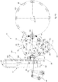
- Fig. 10 is used to describe other forms of embodiment of the conveying station 24, which can be combined with all the forms of embodiment described here, in which the feed device 27 of the packet conveying station 24 can be, or comprise, a conveyor belt 60 with pockets, in particular provided with pockets 62 able to receive the packets 100 with the lateral wings 104 folded, and to keep them stably positioned. In this way, the packets 100 are moved along the conveying path C discretely, autonomous and separated from each other.
- the pockets 62 can receive the packets 100, suitably folded, directly expelled by the thruster 32.
- the pockets 62 are configured to keep the lateral wings 104 inside them, stably in the folded condition, so as to determine the gluing with the internal longitudinal tongues 106 and the consolidation and stabilization of the gluing.
- the pockets 62 can have at least one size mating with the packets 100, in particular for example they can have a width essentially coinciding with a transverse size, in this case the width D, of the packets 100.
- the conveyor belt 60 with pockets can define the conveying path C, which can for example be transverse, in particular orthogonal to the radial direction M of expulsion. If the packet transfer wheel 12 lies on a vertical plane, hence with a horizontal axis of rotation Y, the conveyor belt 60 with pockets, and hence the conveying path C defined by it, can therefore be vertical.
- the conveyor belt 60 with pockets can therefore be a lifter with pockets to move the packets 100 vertically along the conveying path C.
- the conveyor belt 60 with pockets can be the closed-ring type.
- the conveyor belt 60 with pockets receives the packets 100, which are positioned discretely in individual and autonomous pockets 62 and are conveyed in this condition, separated from each other, along the conveying path C, allowing gluing and the stabilization and consolidation of the gluing.
- the packets 100 can be discharged from the conveyor belt 60 with pockets once the functions of gluing, stabilization and consolidation have been completed, for example, but not restrictively, in correspondence with an upper end zone.
- the conveyor belt 60 with pockets is configured to be driven step-wise, in coordination with the movement of rotation of the packet transfer wheel 12, so as to present, on each occasion, an empty pocket 62 in correspondence with the exit station 16, able to receive the packets 100 once they have been folded by the folding device 26 downstream of the exit station 16.
- an accompanier device or counter-thruster 66 can be provided, configured to accompany the expulsion movement of the packets 100 from the exit station 16 in the radial direction M, in particular to accompany the expulsion movement caused by the thruster 32. Therefore, the counter-thruster 66 typically acts in the radial direction M of expulsion, for example functioning as a contrast against the thrust action of the thruster 32. This can be useful for positioning the packets 100 correctly, without risks of deformation and stresses, in the pockets 62.
- the counter-thruster 66 can have a contrast head 68 at the front, provided to cooperate with the packet 100 thrust out from the exit station 16 in the radial direction M.
- the pockets 62 can be provided with an aperture to allow the passage of the counter-thruster 66, in particular of the respective contrast head 68.
- an actuator 64 can be provided, in particular, a kinematic mechanism, for example an articulated quadrilateral, able to drive the counter-thruster 66 with an alternate linear movement, coherent and compatible with the expulsion movement of the packets 100 determined by the thruster 32 in the radial direction M.
- a kinematic mechanism for example an articulated quadrilateral, able to drive the counter-thruster 66 with an alternate linear movement, coherent and compatible with the expulsion movement of the packets 100 determined by the thruster 32 in the radial direction M.
Landscapes
- Engineering & Computer Science (AREA)
- Mechanical Engineering (AREA)
- Wrapping Of Specific Fragile Articles (AREA)
Claims (18)
- Vorrichtung zum Erstellen von Packungen (100) für Rauchartikel (102), wobei die Vorrichtung aufweist:- ein Packung-Transfer-Rad (12), das imstande ist, schrittweise um eine Rotationsachse (Y) zu rotieren, um Packungen (100) entlang eines Transferwegs (P) zwischen einer Eingangsstation (14) und einer Ausgangsstation (16) des Packung-Transfer-Rads (12) zu bewegen,- eine Kleber-Ausgabe-Station (22), die bereitgestellt ist, um Kleber an die Packungen (100) auszugeben,- eine Packung-Förder-Station (24), die konfiguriert ist, um von dem Packung-Transfer-Rad (12) Packungen (100) zu erhalten, an die der Kleber ausgegeben worden ist,- wenigstens eine Faltvorrichtung (26), die stromabwärts von der Ausgangsstation (16) außerhalb des Transferwegs (P) bereitgestellt ist und die konfiguriert ist, um zu klebende seitliche Flügel (104) von den zu erstellenden Packungen (100) zu falten, bevor jene von der Packung-Förder-Station (24) erhalten werden,wobei die Vorrichtung dadurch gekennzeichnet ist, dass sie ferner aufweist:- ein Verpackungs-Rad (20), das stromaufwärts von dem Packung-Transfer-Rad (12) vorliegt und das imstande ist, schrittweise um eine Rotationsachse zu rotieren, die parallel zu der Rotationsachse (Y) des Packung-Transfer-Rads (12) ist, wobei das Verpackungs-Rad (20) konfiguriert ist, um eine Aufeinanderfolge von Packungen (100), die durch nachfolgende Arbeiten zu komplettieren sind, radial zu der Eingangsstation (14) des Packung-Transfer-Rads (12) zuzuführen,wobei die Packungen (100) mit geöffneten und zur Außenseite des Packung-Transfer-Rads (12) hin geneigten seitlichen Flügeln (104) in das Packung-Transfer-Rad (12) eingesetzt werden und der Zustand der geöffneten seitlichen Flügel (104) entlang des gesamten Transferwegs (P) aufrechterhalten wird, wobei die Kleber-Ausgabe-Station (22) außerhalb des Packung-Transfer-Rads (12) ist und entlang des Transferwegs (P) angeordnet ist zwischen der Eingangsstation (14) und der Ausgangsstation (16).
- Vorrichtung gemäß Anspruch 1, dadurch gekennzeichnet, dass die Packung-Förder-Station (24) konfiguriert ist, um die gefalteten seitlichen Flügel (104) zu kleben und um die Klebung der Packungen (100) zu konsolidieren und zu stabilisieren.
- Vorrichtung gemäß Anspruch 1 oder 2, dadurch gekennzeichnet, dass die Packung-Förder-Station (24) zusammenhängt mit einem Eingangsmund (34), um die Packungen (100) von der Ausgangsstation (16) zu erhalten,
und mit einem Förderkanal (25) direkt stromabwärts von dem Eingangsmund (34). - Vorrichtung gemäß Anspruch 1, 2 oder 3, dadurch gekennzeichnet, dass die Packung-Förder-Station (24) mit einer Zuführvorrichtung (27, 60) bereitgestellt ist, die konfiguriert ist, um die Zufuhr der Packungen (100) entlang des Förderwegs (C) zu bestimmen, wobei die Zuführvorrichtung (27) mobile Transportelemente (39) aufweist, die einander gegenüberliegend und im Abstand voneinander angeordnet sind, um eine Durchgangslücke (L) zu definieren, die im Wesentlichen mit einer Querabmessung (D) der Packungen (100) übereinstimmt.
- Vorrichtung gemäß Anspruch 3 oder 3 und 4, dadurch gekennzeichnet, dass der Eingangsmund (34) als eine Durchführung gestaltet ist.
- Vorrichtung gemäß Anspruch 3 und 4 oder 5, wenn abhängig von den Ansprüchen 3 und 4, dadurch gekennzeichnet, dass der Eingangsmund (34) einen Endausgangsabschnitt (34a) hat, der im Wesentlichen tangential zu den mobilen Transportelementen (39) ist.
- Vorrichtung gemäß irgendeinem der Ansprüche 1 bis 6, dadurch gekennzeichnet, dass die Faltvorrichtung (26) aufweist ein mobiles Faltelement (28), das konfiguriert ist, um einen von der Packung (100) zu faltenden seitlichen Flügel (104) einen Faltschub zu zuführen, und ein feststehendes Faltelement (30), das konfiguriert ist, um einen weiteren von der Packung (100) zu faltenden seitlichen Flügel (104) in Anlage zu erhalten.
- Vorrichtung gemäß irgendeinem der Ansprüche 1 bis 6, dadurch gekennzeichnet, dass die Faltvorrichtung (26) aufweist zwei mobile Faltelemente (28), von denen jedes konfiguriert ist, um einem jeweiligen von der Packung (100) zu faltenden seitlichen Flügel (104) einen Faltschub zuzuführen.
- Vorrichtung gemäß irgendeinem der Ansprüche 1 bis 6, dadurch gekennzeichnet, dass die Faltvorrichtung (26) zwei feststehende Faltelemente (30) aufweist, von denen jedes konfiguriert ist, um einen jeweiligen von der Packung (100) zu faltenden seitlichen Flügel (104) in Anlage zu erhalten.
- Vorrichtung gemäß irgendeinem der Ansprüche 1 bis 9, dadurch gekennzeichnet, dass die Packung-Förder-Station (24) mit einem Stoßer (32) bereitgestellt ist, der konfiguriert ist, zumindest um die Packungen (100) von der Ausgabestation (16) zu stoßen und auszutreiben.
- Vorrichtung gemäß irgendeinem Anspruch von 1 bis 10, dadurch gekennzeichnet, dass das Packung-Transfer-Rad (12) aufweist eine Mehrzahl von Packung-Greifköpfen (18), die bereitgestellt sind, um die Packungen (100) entlang des Transferwegs (P) zwischen der Eingangsstation (14) und der Ausgangsstation (16) stabil unterzubringen, wobei jeder der Packung-Greifköpfe (18) mit einer Haltevorrichtung (40) bereitgestellt ist, die konfiguriert ist, um die Packungen (100) selektiv rückzuhalten.
- Vorrichtung gemäß Anspruch 11, dadurch gekennzeichnet, dass jede Haltevorrichtung (40) einen Unterbringungssitz (42) aufweist, der bereitgestellt ist, um darin eine Packung (100) stabil unterzubringen, die den erforderlichen Arbeiten zu unterziehen ist.
- Vorrichtung gemäß Anspruch 12, dadurch gekennzeichnet, dass jeder Unterbringungssitz (42) bereitgestellt ist mit einem Stützboden (46), an dem eine Wand der Packung (100) anliegen kann, und mit seitlichen Wänden (48), wobei die seitlichen Wände (48) bezüglich des Stützbodens (46) geneigt sind, insbesondere zur Außenseite hin geneigt sind, dadurch eine aufgeweitete Gestalt reproduzierend.
- Vorrichtung gemäß irgendeinem Anspruch von 11 bis 13, dadurch gekennzeichnet, dass die Haltevorrichtung (40) aufweist einen mobilen Halter (44), der konfiguriert ist, um eine Offenposition für das Einsetzen der Packungen (100) in den Unterbringungssitz (42) der Packung-Greifköpfe (18) und eine Halteposition einnehmen kann, in welcher er mit dem Durchgang von/zu den Packung-Greifköpfen (18) interferiert.
- Vorrichtung gemäß Anspruch 14, dadurch gekennzeichnet, dass jeder mobile Halter (44) ein Paar mobile Halteelemente (50) aufweist.
- Verfahren zum Erstellen von Packungen (100) für Rauchartikel (102), wobei das Verfahren aufweist:- Bewegen der Packungen (100) entlang eines Transferwegs (P) zwischen einer Eingangsstation (14) und einer Ausgangsstation (16) eines Packung-Transfer-Rads (12),- Ausgeben von Kleber an die Packungen (100) mittels einer Kleber-Ausgabe-Station (22),- Falten, stromabwärts von der Ausgabestation (16) und außerhalb des Transferwegs (P), von zu klebenden seitlichen Flügeln (104) von den Packungen (100), die von dem Packung-Transfer-Rad (12) erhalten werden,wobei das Verfahren dadurch gekennzeichnet ist, dass es aufweist:- radiales Zuführen zu der Eingangsstation (14) des Packung-Transfer-Rads (12) einer Aufeinanderfolge von den Packungen (100), die durch nachfolgende Arbeiten zu komplettieren sind, mittels eines Verpackungsrads (20) stromaufwärts von dem Packung-Transfer-Rad (12),wobei die Packungen (100) in das Packung-Transfer-Rad (12) eingesetzt werden mit den seitlichen Flügeln (104) geöffnet und zu der Außenseite des Packung-Transfer-Rads (12) hin geneigt, wobei der Zustand der geöffneten seitlichen Flügel (104) aufrechterhalten wird entlang des gesamten Transferwegs (P),
wobei die Kleber-Ausgabe-Station (22) außerhalb des Packung-Transfer-Rads (12) ist und entlang des Transferwegs (P) angeordnet ist, sodass die Ausgabe von Kleber durchgeführt wird zwischen der Eingangsstation (14) und der Ausgangsstation (16) . - Verfahren gemäß Anspruch 16, dadurch gekennzeichnet, dass es aufweist:- Kleben, Konsolidieren und Stabilisieren der Klebung der Packungen (100), Fördern der Packungen (100), mit den seitlichen Flügen (104) gefaltet gehalten, zu einer Packung-Förder-Station (24) stromabwärts von dem Packung-Transfer-Rad (12) .
- Verfahren gemäß Anspruch 16 oder 17, dadurch gekennzeichnet, dass es aufweist:- selektives Halten der Packungen (100) in Packung-Greifköpfen (18) des Packung-Transfer-Rads (12) entlang des Transferwegs (P) zwischen der Eingangsstation (14) und der Ausgangsstation (16) .
Priority Applications (1)
| Application Number | Priority Date | Filing Date | Title |
|---|---|---|---|
| PL15741361T PL3172133T3 (pl) | 2014-07-21 | 2015-07-15 | Urządzenie i sposób do wytwarzania opakowań na wyroby do palenia |
Applications Claiming Priority (2)
| Application Number | Priority Date | Filing Date | Title |
|---|---|---|---|
| ITMI20141327 | 2014-07-21 | ||
| PCT/IB2015/055347 WO2016012905A1 (en) | 2014-07-21 | 2015-07-15 | Apparatus and method for making up packets for smoking articles |
Publications (2)
| Publication Number | Publication Date |
|---|---|
| EP3172133A1 EP3172133A1 (de) | 2017-05-31 |
| EP3172133B1 true EP3172133B1 (de) | 2019-05-08 |
Family
ID=51628359
Family Applications (1)
| Application Number | Title | Priority Date | Filing Date |
|---|---|---|---|
| EP15741361.8A Active EP3172133B1 (de) | 2014-07-21 | 2015-07-15 | Vorrichtung und verfahren zur herstellung von packungen für rauchartikel |
Country Status (3)
| Country | Link |
|---|---|
| EP (1) | EP3172133B1 (de) |
| PL (1) | PL3172133T3 (de) |
| WO (1) | WO2016012905A1 (de) |
Cited By (1)
| Publication number | Priority date | Publication date | Assignee | Title |
|---|---|---|---|---|
| IT202100028871A1 (it) * | 2021-11-15 | 2022-02-15 | Ima Spa | Apparato e procedimento per confezionare pacchetti di articoli da fumo. |
Families Citing this family (2)
| Publication number | Priority date | Publication date | Assignee | Title |
|---|---|---|---|---|
| CN108945561B (zh) * | 2018-08-31 | 2024-01-12 | 江苏创源电子有限公司 | 一种包装盒用半自动包膜设备 |
| IT201900000545A1 (it) | 2019-01-14 | 2020-07-14 | Gd Spa | Procedimento e apparecchiatura per confezionare prodotti in pacchetti a forma di scatola |
Citations (4)
| Publication number | Priority date | Publication date | Assignee | Title |
|---|---|---|---|---|
| GB2134870A (en) * | 1983-02-08 | 1984-08-22 | Gd Spa | A cigarette packaging machine |
| EP1321364A1 (de) * | 2001-12-18 | 2003-06-25 | G.D Societ Per Azioni | Zigarettenverpackungsmaschine |
| US7563221B2 (en) * | 2004-03-11 | 2009-07-21 | G.D Societa' Per Azioni | Cigarette packing machine |
| WO2010119472A2 (en) * | 2009-04-17 | 2010-10-21 | Gima S.P.A. | Device for packaging a product in a corresponding container |
Family Cites Families (1)
| Publication number | Priority date | Publication date | Assignee | Title |
|---|---|---|---|---|
| US4979339A (en) | 1989-01-11 | 1990-12-25 | Jones Frederick L | Protective cover with hold-downs |
-
2015
- 2015-07-15 WO PCT/IB2015/055347 patent/WO2016012905A1/en not_active Ceased
- 2015-07-15 PL PL15741361T patent/PL3172133T3/pl unknown
- 2015-07-15 EP EP15741361.8A patent/EP3172133B1/de active Active
Patent Citations (4)
| Publication number | Priority date | Publication date | Assignee | Title |
|---|---|---|---|---|
| GB2134870A (en) * | 1983-02-08 | 1984-08-22 | Gd Spa | A cigarette packaging machine |
| EP1321364A1 (de) * | 2001-12-18 | 2003-06-25 | G.D Societ Per Azioni | Zigarettenverpackungsmaschine |
| US7563221B2 (en) * | 2004-03-11 | 2009-07-21 | G.D Societa' Per Azioni | Cigarette packing machine |
| WO2010119472A2 (en) * | 2009-04-17 | 2010-10-21 | Gima S.P.A. | Device for packaging a product in a corresponding container |
Cited By (3)
| Publication number | Priority date | Publication date | Assignee | Title |
|---|---|---|---|---|
| IT202100028871A1 (it) * | 2021-11-15 | 2022-02-15 | Ima Spa | Apparato e procedimento per confezionare pacchetti di articoli da fumo. |
| WO2023084554A1 (en) * | 2021-11-15 | 2023-05-19 | I.M.A. Industria Macchine Automatiche S.P.A. | Apparatus and method for packaging packets of smoking articles |
| US12534251B2 (en) | 2021-11-15 | 2026-01-27 | I.M.A. Industria Macchine Automatiche S.P.A. | Apparatus and method for packaging packets of smoking articles |
Also Published As
| Publication number | Publication date |
|---|---|
| WO2016012905A1 (en) | 2016-01-28 |
| PL3172133T3 (pl) | 2020-03-31 |
| EP3172133A1 (de) | 2017-05-31 |
Similar Documents
| Publication | Publication Date | Title |
|---|---|---|
| US9844844B2 (en) | Automatic packaging line to pack profiles and rotor | |
| EP0275481B2 (de) | Verfahren und Vorrichtung zum Verpacken von Papier-Taschentüchern | |
| US8733067B2 (en) | Device for packaging a product in a corresponding container | |
| EP2528823B1 (de) | Verpackungsmaschine | |
| EP3269654B1 (de) | Arbeitsstation für eine verpackungslinie und eine verpackungslinie mit mindestens zwei der besagten arbeitsstationen | |
| EP3414194B1 (de) | Verfahren und vorrichtung zum gruppieren von produktrohlingen | |
| ITBO20120169A1 (it) | Macchina e stazione per la formazione di capsule monouso per bevande | |
| WO2016012905A1 (en) | Apparatus and method for making up packets for smoking articles | |
| CN211365107U (zh) | 用于透明膜包装机的上料设备 | |
| US9889959B2 (en) | Tight seal system for the packaging of products | |
| EP3056441A1 (de) | Schlauchbeutelmaschine und verfahren zu ihrem betrieb | |
| CA2295357A1 (en) | Machine for conveying and simultaneously rotating articles, more particularly folding cartons | |
| CN110316424B (zh) | 一种艾条包装机 | |
| US9334071B2 (en) | Apparatus and method for packaging stacks of folded tissue products and the like with a plastic film | |
| CN107406154B (zh) | 用于制造用于香烟的长方体形的包装的设备和方法 | |
| EP2279955B1 (de) | Verfahren und Vorrichtung zum Aufbringen von Etiketten auf Gegenstände | |
| NL1032889C1 (nl) | Grijperkop. | |
| IT9022576A1 (it) | Apparecchiatura per la formazione di pacchi di scatole prodotte da macchine piegatrici-incollatrici o cucitrici imballati con reggia | |
| CN207482696U (zh) | 一种螺旋传输机 | |
| EP3265387B1 (de) | Vorrichtung, verfahren und einrichtung zur bearbeitung von rohlingen zur herstellung von starren packungen für rauchartikel | |
| CN210102215U (zh) | 一种横封拉带式包装装置 | |
| CN106428721A (zh) | 糖果双扭结包装机送料装置 | |
| EP3434609B1 (de) | Faltverfahren und -vorrichtung | |
| EP3976516B1 (de) | Vorrichtung und entsprechendes verfahren zum gruppieren von schachtelzuschnitten von rauchartikeln | |
| CN106218964B (zh) | 一种联动输送装置及应用该联动输送装置的包装机 |
Legal Events
| Date | Code | Title | Description |
|---|---|---|---|
| STAA | Information on the status of an ep patent application or granted ep patent |
Free format text: STATUS: THE INTERNATIONAL PUBLICATION HAS BEEN MADE |
|
| PUAI | Public reference made under article 153(3) epc to a published international application that has entered the european phase |
Free format text: ORIGINAL CODE: 0009012 |
|
| STAA | Information on the status of an ep patent application or granted ep patent |
Free format text: STATUS: REQUEST FOR EXAMINATION WAS MADE |
|
| 17P | Request for examination filed |
Effective date: 20170215 |
|
| AK | Designated contracting states |
Kind code of ref document: A1 Designated state(s): AL AT BE BG CH CY CZ DE DK EE ES FI FR GB GR HR HU IE IS IT LI LT LU LV MC MK MT NL NO PL PT RO RS SE SI SK SM TR |
|
| AX | Request for extension of the european patent |
Extension state: BA ME |
|
| DAV | Request for validation of the european patent (deleted) | ||
| DAX | Request for extension of the european patent (deleted) | ||
| STAA | Information on the status of an ep patent application or granted ep patent |
Free format text: STATUS: EXAMINATION IS IN PROGRESS |
|
| 17Q | First examination report despatched |
Effective date: 20171206 |
|
| GRAP | Despatch of communication of intention to grant a patent |
Free format text: ORIGINAL CODE: EPIDOSNIGR1 |
|
| STAA | Information on the status of an ep patent application or granted ep patent |
Free format text: STATUS: GRANT OF PATENT IS INTENDED |
|
| RIC1 | Information provided on ipc code assigned before grant |
Ipc: B65B 51/02 20060101ALI20181029BHEP Ipc: B65B 61/24 20060101ALI20181029BHEP Ipc: B65B 19/14 20060101ALI20181029BHEP Ipc: B65B 49/08 20060101ALI20181029BHEP Ipc: B65B 61/00 20060101ALI20181029BHEP Ipc: B65B 19/22 20060101AFI20181029BHEP Ipc: B65B 49/02 20060101ALI20181029BHEP |
|
| INTG | Intention to grant announced |
Effective date: 20181205 |
|
| GRAS | Grant fee paid |
Free format text: ORIGINAL CODE: EPIDOSNIGR3 |
|
| GRAA | (expected) grant |
Free format text: ORIGINAL CODE: 0009210 |
|
| STAA | Information on the status of an ep patent application or granted ep patent |
Free format text: STATUS: THE PATENT HAS BEEN GRANTED |
|
| AK | Designated contracting states |
Kind code of ref document: B1 Designated state(s): AL AT BE BG CH CY CZ DE DK EE ES FI FR GB GR HR HU IE IS IT LI LT LU LV MC MK MT NL NO PL PT RO RS SE SI SK SM TR |
|
| REG | Reference to a national code |
Ref country code: GB Ref legal event code: FG4D |
|
| REG | Reference to a national code |
Ref country code: CH Ref legal event code: EP Ref country code: AT Ref legal event code: REF Ref document number: 1129770 Country of ref document: AT Kind code of ref document: T Effective date: 20190515 |
|
| REG | Reference to a national code |
Ref country code: IE Ref legal event code: FG4D |
|
| REG | Reference to a national code |
Ref country code: DE Ref legal event code: R096 Ref document number: 602015029865 Country of ref document: DE |
|
| REG | Reference to a national code |
Ref country code: NL Ref legal event code: MP Effective date: 20190508 |
|
| REG | Reference to a national code |
Ref country code: LT Ref legal event code: MG4D |
|
| PG25 | Lapsed in a contracting state [announced via postgrant information from national office to epo] |
Ref country code: AL Free format text: LAPSE BECAUSE OF FAILURE TO SUBMIT A TRANSLATION OF THE DESCRIPTION OR TO PAY THE FEE WITHIN THE PRESCRIBED TIME-LIMIT Effective date: 20190508 Ref country code: ES Free format text: LAPSE BECAUSE OF FAILURE TO SUBMIT A TRANSLATION OF THE DESCRIPTION OR TO PAY THE FEE WITHIN THE PRESCRIBED TIME-LIMIT Effective date: 20190508 Ref country code: SE Free format text: LAPSE BECAUSE OF FAILURE TO SUBMIT A TRANSLATION OF THE DESCRIPTION OR TO PAY THE FEE WITHIN THE PRESCRIBED TIME-LIMIT Effective date: 20190508 Ref country code: PT Free format text: LAPSE BECAUSE OF FAILURE TO SUBMIT A TRANSLATION OF THE DESCRIPTION OR TO PAY THE FEE WITHIN THE PRESCRIBED TIME-LIMIT Effective date: 20190908 Ref country code: NO Free format text: LAPSE BECAUSE OF FAILURE TO SUBMIT A TRANSLATION OF THE DESCRIPTION OR TO PAY THE FEE WITHIN THE PRESCRIBED TIME-LIMIT Effective date: 20190808 Ref country code: HR Free format text: LAPSE BECAUSE OF FAILURE TO SUBMIT A TRANSLATION OF THE DESCRIPTION OR TO PAY THE FEE WITHIN THE PRESCRIBED TIME-LIMIT Effective date: 20190508 Ref country code: NL Free format text: LAPSE BECAUSE OF FAILURE TO SUBMIT A TRANSLATION OF THE DESCRIPTION OR TO PAY THE FEE WITHIN THE PRESCRIBED TIME-LIMIT Effective date: 20190508 Ref country code: FI Free format text: LAPSE BECAUSE OF FAILURE TO SUBMIT A TRANSLATION OF THE DESCRIPTION OR TO PAY THE FEE WITHIN THE PRESCRIBED TIME-LIMIT Effective date: 20190508 Ref country code: LT Free format text: LAPSE BECAUSE OF FAILURE TO SUBMIT A TRANSLATION OF THE DESCRIPTION OR TO PAY THE FEE WITHIN THE PRESCRIBED TIME-LIMIT Effective date: 20190508 |
|
| PG25 | Lapsed in a contracting state [announced via postgrant information from national office to epo] |
Ref country code: LV Free format text: LAPSE BECAUSE OF FAILURE TO SUBMIT A TRANSLATION OF THE DESCRIPTION OR TO PAY THE FEE WITHIN THE PRESCRIBED TIME-LIMIT Effective date: 20190508 Ref country code: RS Free format text: LAPSE BECAUSE OF FAILURE TO SUBMIT A TRANSLATION OF THE DESCRIPTION OR TO PAY THE FEE WITHIN THE PRESCRIBED TIME-LIMIT Effective date: 20190508 Ref country code: BG Free format text: LAPSE BECAUSE OF FAILURE TO SUBMIT A TRANSLATION OF THE DESCRIPTION OR TO PAY THE FEE WITHIN THE PRESCRIBED TIME-LIMIT Effective date: 20190808 Ref country code: GR Free format text: LAPSE BECAUSE OF FAILURE TO SUBMIT A TRANSLATION OF THE DESCRIPTION OR TO PAY THE FEE WITHIN THE PRESCRIBED TIME-LIMIT Effective date: 20190809 |
|
| REG | Reference to a national code |
Ref country code: AT Ref legal event code: MK05 Ref document number: 1129770 Country of ref document: AT Kind code of ref document: T Effective date: 20190508 |
|
| RAP2 | Party data changed (patent owner data changed or rights of a patent transferred) |
Owner name: I.M.A. INDUSTRIA MACCHINE AUTOMATICHE S.P.A |
|
| PG25 | Lapsed in a contracting state [announced via postgrant information from national office to epo] |
Ref country code: SK Free format text: LAPSE BECAUSE OF FAILURE TO SUBMIT A TRANSLATION OF THE DESCRIPTION OR TO PAY THE FEE WITHIN THE PRESCRIBED TIME-LIMIT Effective date: 20190508 Ref country code: DK Free format text: LAPSE BECAUSE OF FAILURE TO SUBMIT A TRANSLATION OF THE DESCRIPTION OR TO PAY THE FEE WITHIN THE PRESCRIBED TIME-LIMIT Effective date: 20190508 Ref country code: AT Free format text: LAPSE BECAUSE OF FAILURE TO SUBMIT A TRANSLATION OF THE DESCRIPTION OR TO PAY THE FEE WITHIN THE PRESCRIBED TIME-LIMIT Effective date: 20190508 Ref country code: EE Free format text: LAPSE BECAUSE OF FAILURE TO SUBMIT A TRANSLATION OF THE DESCRIPTION OR TO PAY THE FEE WITHIN THE PRESCRIBED TIME-LIMIT Effective date: 20190508 Ref country code: RO Free format text: LAPSE BECAUSE OF FAILURE TO SUBMIT A TRANSLATION OF THE DESCRIPTION OR TO PAY THE FEE WITHIN THE PRESCRIBED TIME-LIMIT Effective date: 20190508 Ref country code: CZ Free format text: LAPSE BECAUSE OF FAILURE TO SUBMIT A TRANSLATION OF THE DESCRIPTION OR TO PAY THE FEE WITHIN THE PRESCRIBED TIME-LIMIT Effective date: 20190508 |
|
| REG | Reference to a national code |
Ref country code: DE Ref legal event code: R097 Ref document number: 602015029865 Country of ref document: DE |
|
| RAP2 | Party data changed (patent owner data changed or rights of a patent transferred) |
Owner name: I.M.A. INDUSTRIA MACCHINE AUTOMATICHE S.P.A. |
|
| PG25 | Lapsed in a contracting state [announced via postgrant information from national office to epo] |
Ref country code: MC Free format text: LAPSE BECAUSE OF FAILURE TO SUBMIT A TRANSLATION OF THE DESCRIPTION OR TO PAY THE FEE WITHIN THE PRESCRIBED TIME-LIMIT Effective date: 20190508 Ref country code: SM Free format text: LAPSE BECAUSE OF FAILURE TO SUBMIT A TRANSLATION OF THE DESCRIPTION OR TO PAY THE FEE WITHIN THE PRESCRIBED TIME-LIMIT Effective date: 20190508 |
|
| REG | Reference to a national code |
Ref country code: CH Ref legal event code: PL |
|
| PLBE | No opposition filed within time limit |
Free format text: ORIGINAL CODE: 0009261 |
|
| STAA | Information on the status of an ep patent application or granted ep patent |
Free format text: STATUS: NO OPPOSITION FILED WITHIN TIME LIMIT |
|
| PG25 | Lapsed in a contracting state [announced via postgrant information from national office to epo] |
Ref country code: TR Free format text: LAPSE BECAUSE OF FAILURE TO SUBMIT A TRANSLATION OF THE DESCRIPTION OR TO PAY THE FEE WITHIN THE PRESCRIBED TIME-LIMIT Effective date: 20190508 |
|
| 26N | No opposition filed |
Effective date: 20200211 |
|
| REG | Reference to a national code |
Ref country code: BE Ref legal event code: MM Effective date: 20190731 |
|
| GBPC | Gb: european patent ceased through non-payment of renewal fee |
Effective date: 20190808 |
|
| PG25 | Lapsed in a contracting state [announced via postgrant information from national office to epo] |
Ref country code: SI Free format text: LAPSE BECAUSE OF FAILURE TO SUBMIT A TRANSLATION OF THE DESCRIPTION OR TO PAY THE FEE WITHIN THE PRESCRIBED TIME-LIMIT Effective date: 20190508 Ref country code: BE Free format text: LAPSE BECAUSE OF NON-PAYMENT OF DUE FEES Effective date: 20190731 Ref country code: CH Free format text: LAPSE BECAUSE OF NON-PAYMENT OF DUE FEES Effective date: 20190731 Ref country code: LU Free format text: LAPSE BECAUSE OF NON-PAYMENT OF DUE FEES Effective date: 20190715 Ref country code: LI Free format text: LAPSE BECAUSE OF NON-PAYMENT OF DUE FEES Effective date: 20190731 |
|
| PG25 | Lapsed in a contracting state [announced via postgrant information from national office to epo] |
Ref country code: FR Free format text: LAPSE BECAUSE OF NON-PAYMENT OF DUE FEES Effective date: 20190731 |
|
| PG25 | Lapsed in a contracting state [announced via postgrant information from national office to epo] |
Ref country code: IE Free format text: LAPSE BECAUSE OF NON-PAYMENT OF DUE FEES Effective date: 20190715 |
|
| PG25 | Lapsed in a contracting state [announced via postgrant information from national office to epo] |
Ref country code: GB Free format text: LAPSE BECAUSE OF NON-PAYMENT OF DUE FEES Effective date: 20190808 |
|
| PG25 | Lapsed in a contracting state [announced via postgrant information from national office to epo] |
Ref country code: CY Free format text: LAPSE BECAUSE OF FAILURE TO SUBMIT A TRANSLATION OF THE DESCRIPTION OR TO PAY THE FEE WITHIN THE PRESCRIBED TIME-LIMIT Effective date: 20190508 |
|
| PG25 | Lapsed in a contracting state [announced via postgrant information from national office to epo] |
Ref country code: IS Free format text: LAPSE BECAUSE OF FAILURE TO SUBMIT A TRANSLATION OF THE DESCRIPTION OR TO PAY THE FEE WITHIN THE PRESCRIBED TIME-LIMIT Effective date: 20190908 |
|
| PG25 | Lapsed in a contracting state [announced via postgrant information from national office to epo] |
Ref country code: MT Free format text: LAPSE BECAUSE OF FAILURE TO SUBMIT A TRANSLATION OF THE DESCRIPTION OR TO PAY THE FEE WITHIN THE PRESCRIBED TIME-LIMIT Effective date: 20190508 Ref country code: HU Free format text: LAPSE BECAUSE OF FAILURE TO SUBMIT A TRANSLATION OF THE DESCRIPTION OR TO PAY THE FEE WITHIN THE PRESCRIBED TIME-LIMIT; INVALID AB INITIO Effective date: 20150715 |
|
| PG25 | Lapsed in a contracting state [announced via postgrant information from national office to epo] |
Ref country code: MK Free format text: LAPSE BECAUSE OF FAILURE TO SUBMIT A TRANSLATION OF THE DESCRIPTION OR TO PAY THE FEE WITHIN THE PRESCRIBED TIME-LIMIT Effective date: 20190508 |
|
| P01 | Opt-out of the competence of the unified patent court (upc) registered |
Effective date: 20230508 |
|
| PGFP | Annual fee paid to national office [announced via postgrant information from national office to epo] |
Ref country code: PL Payment date: 20250610 Year of fee payment: 11 |
|
| PGFP | Annual fee paid to national office [announced via postgrant information from national office to epo] |
Ref country code: DE Payment date: 20250723 Year of fee payment: 11 |
|
| PGFP | Annual fee paid to national office [announced via postgrant information from national office to epo] |
Ref country code: IT Payment date: 20250722 Year of fee payment: 11 |