EP3172105B1 - Lichtsignal - Google Patents
Lichtsignal Download PDFInfo
- Publication number
- EP3172105B1 EP3172105B1 EP15760134.5A EP15760134A EP3172105B1 EP 3172105 B1 EP3172105 B1 EP 3172105B1 EP 15760134 A EP15760134 A EP 15760134A EP 3172105 B1 EP3172105 B1 EP 3172105B1
- Authority
- EP
- European Patent Office
- Prior art keywords
- shielding plate
- light signal
- light
- signal
- electronic components
- Prior art date
- Legal status (The legal status is an assumption and is not a legal conclusion. Google has not performed a legal analysis and makes no representation as to the accuracy of the status listed.)
- Active
Links
Images
Classifications
-
- B—PERFORMING OPERATIONS; TRANSPORTING
- B61—RAILWAYS
- B61L—GUIDING RAILWAY TRAFFIC; ENSURING THE SAFETY OF RAILWAY TRAFFIC
- B61L5/00—Local operating mechanisms for points or track-mounted scotch-blocks; Visible or audible signals; Local operating mechanisms for visible or audible signals
- B61L5/12—Visible signals
- B61L5/18—Light signals; Mechanisms associated therewith, e.g. blinders
-
- B—PERFORMING OPERATIONS; TRANSPORTING
- B61—RAILWAYS
- B61L—GUIDING RAILWAY TRAFFIC; ENSURING THE SAFETY OF RAILWAY TRAFFIC
- B61L5/00—Local operating mechanisms for points or track-mounted scotch-blocks; Visible or audible signals; Local operating mechanisms for visible or audible signals
- B61L5/12—Visible signals
- B61L5/18—Light signals; Mechanisms associated therewith, e.g. blinders
- B61L5/1809—Daylight signals
- B61L5/1881—Wiring diagrams for power supply, control or testing
-
- B—PERFORMING OPERATIONS; TRANSPORTING
- B61—RAILWAYS
- B61L—GUIDING RAILWAY TRAFFIC; ENSURING THE SAFETY OF RAILWAY TRAFFIC
- B61L2207/00—Features of light signals
- B61L2207/02—Features of light signals using light-emitting diodes [LEDs]
Definitions
- the invention relates to a light signal, in particular for railway safety systems, with electronic components and a power dissipation arrangement for converting electrical power into heat, the electronic components being arranged in a signal transmitter housing which is connected to a chute for reducing phantom light.
- light signals serve as signal generators or symbol indicators, which convey certain information by driving and / or shaping a luminous surface, that is to say by means of the radiation characteristic. This is often security-relevant information that must not be falsified or blended by extraneous light.
- the undesired lighting up or falsification of a light point by the incidence of ambient light, for example sunlight or headlight light, is referred to as a phantom effect.
- the signal generator housings of the light signals are usually connected to a roof-like extension, the so-called chute.
- Light signals often have to ensure a certain power consumption for reasons of compatibility. If this power consumption is actually not required, for example in the case of LED signal transmitters, an additional consumer which converts the remaining power into heat is required for power adjustment.
- a known power dissipation arrangement consists of resistors which are mounted on a heat sink within the signal generator housing.
- the resistors In order to achieve the required insulation properties of the circuit, the resistors must be connected at a minimum distance of several millimeters to other components. In addition to this spacing, the disadvantage is above all the heat development within the signal generator housing.
- This heat development has, among other things, a very negative influence on the degradation, i.e. the aging behavior, of the electronic components, for example the LEDs.
- the GB 2 390 669 A as well as from the DE 10 2011 084 166 A1 the shift of the power dissipation arrangement into the housing wall is known.
- the power dissipation arrangement is assigned to the optics holder.
- the invention has for its object to eliminate these disadvantages and to provide a light signal of the generic type, in which heating of the electronic components is avoided by the power dissipation arrangement.
- the object is achieved according to the invention by the subject matter that the power dissipation arrangement is assigned to the barge.
- the cooling takes place by means of the free draft on the peripheral surface of the barge.
- the existing barge is used as a heat sink, so that costs can be reduced.
- the chute and the signal transmitter consist of a few components that can be assembled together in a compact signal screen. Neither the signal shield nor the signal transmitter are heated by the chute-side power dissipation arrangement.
- the chute consists of thermally insulating material.
- plastic is used as the bulk material according to claim 3.
- Barges usually consist of metallic material, which, however, has poor thermal insulation.
- a plastic barge is also considerably lighter and cheaper than a metallic version.
- the power dissipation device is designed as a bar heater. Targeted heating of the barge counteracts its impairment due to snow and ice.
- the barge heater is preferably designed as a heating element embedded in an upper roof area of the barge. This will result in the power dissipation requirements largely combined with the frost protection requirements.
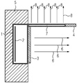
- the invention is explained in more detail below with the aid of a figurative representation.
- the figure shows a schematic representation of a light signal in longitudinal section.
- the light signal essentially consists of a signal transmitter housing 1 for receiving electronic components 2 and a lens arrangement 3 as well as a roof-like chute 4 for phantom light reduction and a stabilizing compact signal screen 5.
- the electronic components 2 inside the signal transmitter housing 1 comprise LEDs for light emission and their triggering signal transmitter electronics.
- a power consumption is provided which exceeds the actual requirements of the electronic components in the embodiment shown.
- the unneeded power must be converted to heat by a power dissipation arrangement.
- This power dissipation arrangement is arranged in the chute 4 in the form of a chute heater 7. This results in the possibility of simultaneously using the power dissipation arrangement for the targeted heating of the barge 4, as a result of which winter weather influences are reduced.
- the heat 8 of the barn heater 7 is entirely released into the ambient air.
- the bar 4 is designed as a plastic bar.
- the light signal shown is characterized above all by avoiding degradation-causing heating of the electronic components 2 and by simple and space-saving construction.
Landscapes
- Engineering & Computer Science (AREA)
- Mechanical Engineering (AREA)
- Cooling Or The Like Of Electrical Apparatus (AREA)
- Shielding Devices Or Components To Electric Or Magnetic Fields (AREA)
- Arrangement Of Elements, Cooling, Sealing, Or The Like Of Lighting Devices (AREA)
Description
- Die Erfindung betrifft ein Lichtsignal, insbesondere für Eisenbahnsicherungsanlagen, mit elektronischen Bauelementen und einer Leistungsabführungsanordnung zur Umwandlung elektrischer Leistung in Wärme, wobei die elektronischen Bauelemente in einem Signalgebergehäuse angeordnet sind, welches mit einer Schute zur Reduzierung von Phantomlicht verbunden ist.
- Die nachfolgende Beschreibung bezieht sich im Wesentlichen auf Lichtsignale zur Darstellung von Signalbegriffen bei schienengebundenen Verkehrswegen, ohne dass der beanspruchte Gegenstand auf diese Anwendung beschränkt ist. Vielmehr ist eine Anwendung für jegliche signalgesteuerte Verkehrswege sowie auch im industriellen Bereich denkbar.
- Prinzipiell dienen Lichtsignale als Signalgeber oder Symbolanzeiger, die durch Fahrt- und/oder Formgebung einer Leuchtfläche, das heißt durch die Abstrahlcharakteristik, bestimmte Informationen vermitteln. Dabei handelt es sich häufig um sicherheitsrelevante Informationen, die keinesfalls optisch verfälscht oder durch Fremdlicht überblendet sein dürfen. Das unerwünschte Aufleuchten beziehungsweise Verfälschen eines Lichtpunktes durch Einfall von Umgebungslicht, zum Beispiel Sonnenlicht oder Scheinwerferlicht, wird als Phantomeffekt bezeichnet. Um Phantomlicht entgegenzuwirken, sind die Signalgebergehäuse der Lichtsignale üblicherweise mit einer dachartigen Verlängerung, der sogenannten Schute, verbunden.
- Häufig müssen Lichtsignale aus Kompatibilitätsgründen eine bestimmte Leistungsaufnahme gewährleisten. Falls diese Leistungsaufnahme eigentlich nicht erforderlich ist, beispielsweise bei LED-Signalgebern, ist zur Leistungsanpassung ein zusätzlicher Verbraucher, der die Restleistung in Wärme umsetzt, erforderlich.
- Eine bekannte Leistungsabführungsanordnung besteht aus Widerständen, die innerhalb des Signalgebergehäuses auf einem Kühlkörper montiert sind. Um die geforderten Isoliereigenschaften des Stromkreises zu realisieren, müssen die Widerstände in einem Mindestabstand von mehreren Millimetern zu anderen Bauelementen angeschlossen werden. Nachteilig ist neben dieser Beabstandung vor allem die Wärmeentwicklung innerhalb des Signalgebergehäuses.
- Diese Wärmeentwicklung hat unter anderem einen sehr negativen Einfluss auf die Degradation, das heißt das Alterungsverhalten, der elektronischen Bauelemente, beispielsweise der LEDs. Um eine bessere Wärmeabführung zu erreichen, ist aus der
GB 2 390 669 A DE 10 2011 084 166 A1 die Verlagerung der Leistungsabführungsanordnung in die Gehäusewandung bekannt. Gemäß derDE 10 2012 205 052 A1 ist die Leistungsabführungsanordnung dem Optikhalter zugeordnet. - Ein weiteres Lichtsignal mit Leistungsabführungsanordnung wird in
US 5 785 418 offenbart. - Nachteilig auch bei diesen Varianten ist, dass zumindest ein Teil der Wärme in das Gehäuseinnere gelangt, wodurch die elektronischen Bauelemente degradationsverschlechternd aufgeheizt werden.
- Der Erfindung liegt die Aufgabe zugrunde, diese Nachteile zu beseitigen und ein Lichtsignal der gattungsgemäßen Art anzugeben, bei dem eine Aufheizung der elektronischen Bauelemente durch die Leistungsabführungsanordnung vermieden wird.
- Die Aufgabe wird erfindungsgemäß durch den Gegenstand nach Anspruch 1 gelöst, dass die Leistungsabführungsanordnung der Schute zugeordnet ist.
- Auf diese Weise wird die gesamte, durch die zu hohe Leistungsaufnahme des Lichtsignals verursachte Wärmemenge nach außen abgeführt. Zusätzliche Kühlkörper im Gehäuseinneren können entfallen. Dadurch verringert sich die Einbautiefe des Signalgebergehäuses. Das Abstandsproblem der Leistungswiderstände auf dem Kühlkörper besteht bei der erfindungsgemäßen Anordnung der Leistungsabführungsanordnung nicht mehr. Dadurch entfällt auch die aufwendige Montage der Widerstände. Die Kosten für Kühlkörper und besonders präziser Montage der Widerstände entfallen. Besonders vorteilhaft ist die Vermeidung der Erwärmung der elektronischen Bauelemente bei der Verwendung von Kompaktsignalschirmen.
- Die Kühlung erfolgt mittels des freien Luftzuges an der peripheren Oberfläche der Schute. Als Kühlkörper wird die vorhandene Schute verwendet, so dass Kosten reduziert werden können. Die Schute und der Signalgeber bestehen aus wenigen Bauteilen, die gemeinsam in einen Kompaktsignalschirm montiert werden können. Weder der Signalschirm noch der Signalgeber werden durch die schutenseitige Leistungsabführungsanordnung erwärmt.
- Gemäß Anspruch 2 ist vorgesehen, dass die Schute aus thermisch isolierendem Material besteht. Dadurch wird eine noch weitergehende Freihaltung des Signalgebergehäuses und der darin befindlichen elektronischen Bauelemente von Wärmebelastung erreicht.
- Insbesondere wird gemäß Anspruch 3 als Schutenmaterial Kunststoff verwendet. Üblicherweise bestehen Schuten aus metallischem Material, welches jedoch eine schlechte thermische Isolierung aufweist. Eine Kunststoffschute ist gegenüber einer metallischen Ausführung außerdem wesentlich leichter und preisgünstiger.
- Erfindungsgemäß ist die Leistungsabführungseinrichtung als Schutenheizung ausgebildet. Durch gezielte Erwärmung der Schute wird deren Beeinträchtigung durch Schnee und Eis entgegengewirkt.
- Dabei ist die Schutenheizung gemäß Anspruch 4 vorzugsweise als in einem oberen Dachbereich der Schute eingebettetes Heizelement ausgebildet. Dadurch werden die Leistungsabführungsanforderungen mit den Frostschutzanforderungen weitestgehend kombiniert.
- Die Erfindung wird nachfolgend anhand einer figürlichen Darstellung näher erläutert. Die Figur zeigt eine schematische Darstellung eines Lichtsignals in Längsschnitt.
- Das Lichtsignal besteht im Wesentlichen aus einem Signalgebergehäuse 1 zur Aufnahme elektronischer Bauelemente 2 und einer Linsenanordnung 3 sowie einer dachartigen Schute 4 zur Phantomlichtreduzierung und einem stabilisierenden Kompaktsignalschirm 5. Die elektronischen Bauelemente 2 im Inneren des Signalgebergehäuses 1 umfassen LEDs zur Lichtemission und deren ansteuernde Signalgeberelektronik.
- Um wesentliche Bauteile des Lichtsignals als Substitut für andere Ausführungsformen verwenden zu können, ist eine Leistungsaufnahme vorgesehen, die dem eigentlichen Bedarf der elektronischen Bauelemente in der dargestellten Ausführungsform übersteigt. Infolgedessen muss die nicht benötigte Leistung durch eine Leistungsabführungsanordnung in Wärme umgewandelt werden. Diese Leistungsabführungsanordnung ist in der Schute 4 in Form einer Schutenheizung 7 angeordnet. Dadurch ergibt sich die Möglichkeit, die Leistungsabführungsanordnung gleichzeitig zur gezielten Heizung der Schute 4 zu verwenden, wodurch winterliche Witterungseinflüsse verringert werden. Die Wärme 8 der Schutenheizung 7 wird zur Gänze an die Umgebungsluft abgegeben. Um die Schutenheizung 7 thermisch gegenüber dem Kontaktsignalschirm 6 mit dem Signalgebergehäuse 1 und den elektronischen Bauelementen 2 möglichst wirkungsvoll zu isolieren, ist die Schute 4 als Kunststoffschute ausgebildet.
- Das dargestellte Lichtsignal zeichnet sich vor allem durch Vermeidung einer degradationsverschlechternden Aufheizung der elektronischen Bauelemente 2 sowie durch einfache und raumsparende Bauweise aus.
Claims (4)
- Lichtsignal, insbesondere für Eisenbahnsicherungsanlagen, mit elektronischen Bauelementen (2), und einer Leistungsabführungsanordnung zur Umwandlung elektrischer Leistung in Wärme (8), wobei die elektronischen Bauelemente (2) in einem Signalgebergehäuse (1) angeordnet sind, welches mit einer Schute (4) zur Reduzierung von Phantomlicht verbunden ist,
dadurch gekennzeichnet, dass die Leistungsabführungsanordnung der Schute (4) zugeordnet und als Schutenheizung (7) ausgebildet ist, wobei die Schutenheizung (7) als ein in der Schute (4) eingebettetes Heizelement ausgebildet ist. - Lichtsignal nach Anspruch 1,
dadurch gekennzeichnet, dass die Schute (4) aus thermisch isolierendem Material besteht. - Lichtsignal nach einem der vorangehenden Ansprüche,
dadurch gekennzeichnet, dass die Schute (4) als Kunststoffschute ausgebildet ist. - Lichtsignal nach einem der vorangehenden Ansprüche,
dadurch gekennzeichnet, dass die Schutenheizung (7) als in einem oberen Dachbereich der Schute (4) eingebettetes Heizelement ausgebildet ist.
Applications Claiming Priority (2)
| Application Number | Priority Date | Filing Date | Title |
|---|---|---|---|
| DE102014218881.4A DE102014218881A1 (de) | 2014-09-19 | 2014-09-19 | Lichtsignal |
| PCT/EP2015/070018 WO2016041774A1 (de) | 2014-09-19 | 2015-09-02 | Lichtsignal |
Publications (2)
| Publication Number | Publication Date |
|---|---|
| EP3172105A1 EP3172105A1 (de) | 2017-05-31 |
| EP3172105B1 true EP3172105B1 (de) | 2020-07-22 |
Family
ID=54065347
Family Applications (1)
| Application Number | Title | Priority Date | Filing Date |
|---|---|---|---|
| EP15760134.5A Active EP3172105B1 (de) | 2014-09-19 | 2015-09-02 | Lichtsignal |
Country Status (5)
| Country | Link |
|---|---|
| EP (1) | EP3172105B1 (de) |
| CN (1) | CN107074256A (de) |
| DE (1) | DE102014218881A1 (de) |
| ES (1) | ES2824225T3 (de) |
| WO (1) | WO2016041774A1 (de) |
Cited By (1)
| Publication number | Priority date | Publication date | Assignee | Title |
|---|---|---|---|---|
| EP4253186A1 (de) * | 2022-03-30 | 2023-10-04 | Siemens Mobility AG | Lichtsignal zur steuerung eines verkehrsmittels |
Family Cites Families (13)
| Publication number | Priority date | Publication date | Assignee | Title |
|---|---|---|---|---|
| DE3137718A1 (de) * | 1981-09-22 | 1983-04-07 | Siemens AG, 1000 Berlin und 8000 München | Signalgeber |
| US5785418A (en) * | 1996-06-27 | 1998-07-28 | Hochstein; Peter A. | Thermally protected LED array |
| GB2390669B (en) | 1999-11-26 | 2004-03-10 | Dorman Traffic Products Ltd | Signal apparatus |
| CN102128434A (zh) * | 2010-01-14 | 2011-07-20 | 戴胜祝 | Led灯的防积雪装置 |
| CN102353010B (zh) * | 2011-09-02 | 2013-12-18 | 房雪锋 | 声光应急控制太阳能热电互补led灯具 |
| CN102506371B (zh) * | 2011-09-02 | 2015-06-17 | 山东佛光照明科技有限公司 | 风光热电互补led路灯装置 |
| DE102011084166A1 (de) * | 2011-10-07 | 2013-04-11 | Siemens Aktiengesellschaft | Elektronisches Gerät |
| DE102012205052A1 (de) * | 2012-03-29 | 2013-10-02 | Siemens Aktiengesellschaft | Signalgeber |
| EP2653365B1 (de) * | 2012-04-18 | 2014-06-04 | Siemens Schweiz AG | Lichtsignal enthaltend eine LED-Lichtquellen-Anordnung zum Ersatz einer Glühlampen-Anordnung |
| CN202976491U (zh) * | 2012-11-01 | 2013-06-05 | 尾扎拿加彭错 | 防冻除霜交通信号灯 |
| CN103256550A (zh) * | 2013-06-05 | 2013-08-21 | 弓伟南 | 新型led道路照明灯具 |
| CN203633019U (zh) * | 2014-01-04 | 2014-06-04 | 山东淄博星志电子有限公司 | 信号机机壳 |
| CN103963697A (zh) * | 2014-05-30 | 2014-08-06 | 李宝 | 车载警灯除雪装置 |
-
2014
- 2014-09-19 DE DE102014218881.4A patent/DE102014218881A1/de not_active Ceased
-
2015
- 2015-09-02 WO PCT/EP2015/070018 patent/WO2016041774A1/de not_active Ceased
- 2015-09-02 EP EP15760134.5A patent/EP3172105B1/de active Active
- 2015-09-02 CN CN201580050481.XA patent/CN107074256A/zh active Pending
- 2015-09-02 ES ES15760134T patent/ES2824225T3/es active Active
Non-Patent Citations (1)
| Title |
|---|
| None * |
Cited By (1)
| Publication number | Priority date | Publication date | Assignee | Title |
|---|---|---|---|---|
| EP4253186A1 (de) * | 2022-03-30 | 2023-10-04 | Siemens Mobility AG | Lichtsignal zur steuerung eines verkehrsmittels |
Also Published As
| Publication number | Publication date |
|---|---|
| DE102014218881A1 (de) | 2016-03-24 |
| CN107074256A (zh) | 2017-08-18 |
| ES2824225T3 (es) | 2021-05-11 |
| EP3172105A1 (de) | 2017-05-31 |
| WO2016041774A1 (de) | 2016-03-24 |
Similar Documents
| Publication | Publication Date | Title |
|---|---|---|
| EP3210444B1 (de) | Kraftfahrzeug-aussenleuchte | |
| DE102008059320B4 (de) | Elektronische Geräteanordnung und Kühlkörper hierfür | |
| EP3172105A1 (de) | Lichtsignal | |
| DE102019207011B4 (de) | Sichtscheibe für ein Kraftfahrzeug und System umfassend die Sichtscheibe | |
| DE102013205439A1 (de) | Lichtsignal | |
| DE102008030353B4 (de) | Fahrzeugleuchte mit einem Wärme leitenden Kunststoff | |
| CH699414A2 (de) | Bodennahes Lichtsignal. | |
| WO2011157597A1 (de) | Lichtsignal | |
| DE102008023683A1 (de) | Halterung für elektrische Bauelemente mit hoher thermischer Isolationsfähigkeit | |
| EP3537039A1 (de) | Verkapselungsschlauch für ein lineares leuchtdiodenmodul und lineares leuchtdiodenmodul damit | |
| DE102013218826A1 (de) | Kühlkörper | |
| DE102012205052A1 (de) | Signalgeber | |
| EP3218243B1 (de) | Lichtsignal | |
| EP2653365B1 (de) | Lichtsignal enthaltend eine LED-Lichtquellen-Anordnung zum Ersatz einer Glühlampen-Anordnung | |
| DE212013000260U1 (de) | Leuchtmittel, insbesondere LED-Modul | |
| DE102013214342A1 (de) | Lichtsignal | |
| EP3077251A1 (de) | Leuchteinrichtung für schienenfahrzeuge | |
| DE102014205225A1 (de) | Signalgeber zur Abgabe eines Lichtsignals | |
| DE102014004762B4 (de) | LED-Umrüstsatz für Außenleuchten | |
| EP2581657B1 (de) | Kühlkörper-Anordnung für eine LED-Leuchte sowie LED-Leuchte | |
| EP2539877A1 (de) | Symbolanzeiger | |
| DE202013000149U1 (de) | Beleuchtungsvorrichtung für Motorradschutzhelm | |
| EP3211303B1 (de) | Led-modul | |
| DE102015205332A1 (de) | Transluzente mit LED bestückte Boards und/oder Kühlkörper | |
| DE202015105174U1 (de) | Lichtmodul für Scheinwerfer und Scheinwerfer mit einem solchen Lichtmodul |
Legal Events
| Date | Code | Title | Description |
|---|---|---|---|
| STAA | Information on the status of an ep patent application or granted ep patent |
Free format text: STATUS: THE INTERNATIONAL PUBLICATION HAS BEEN MADE |
|
| PUAI | Public reference made under article 153(3) epc to a published international application that has entered the european phase |
Free format text: ORIGINAL CODE: 0009012 |
|
| STAA | Information on the status of an ep patent application or granted ep patent |
Free format text: STATUS: REQUEST FOR EXAMINATION WAS MADE |
|
| 17P | Request for examination filed |
Effective date: 20170221 |
|
| AK | Designated contracting states |
Kind code of ref document: A1 Designated state(s): AL AT BE BG CH CY CZ DE DK EE ES FI FR GB GR HR HU IE IS IT LI LT LU LV MC MK MT NL NO PL PT RO RS SE SI SK SM TR |
|
| AX | Request for extension of the european patent |
Extension state: BA ME |
|
| RAP1 | Party data changed (applicant data changed or rights of an application transferred) |
Owner name: SIEMENS AKTIENGESELLSCHAFT |
|
| DAV | Request for validation of the european patent (deleted) | ||
| DAX | Request for extension of the european patent (deleted) | ||
| RAP1 | Party data changed (applicant data changed or rights of an application transferred) |
Owner name: SIEMENS MOBILITY GMBH |
|
| STAA | Information on the status of an ep patent application or granted ep patent |
Free format text: STATUS: EXAMINATION IS IN PROGRESS |
|
| 17Q | First examination report despatched |
Effective date: 20191023 |
|
| GRAP | Despatch of communication of intention to grant a patent |
Free format text: ORIGINAL CODE: EPIDOSNIGR1 |
|
| STAA | Information on the status of an ep patent application or granted ep patent |
Free format text: STATUS: GRANT OF PATENT IS INTENDED |
|
| INTG | Intention to grant announced |
Effective date: 20200320 |
|
| GRAS | Grant fee paid |
Free format text: ORIGINAL CODE: EPIDOSNIGR3 |
|
| GRAA | (expected) grant |
Free format text: ORIGINAL CODE: 0009210 |
|
| STAA | Information on the status of an ep patent application or granted ep patent |
Free format text: STATUS: THE PATENT HAS BEEN GRANTED |
|
| AK | Designated contracting states |
Kind code of ref document: B1 Designated state(s): AL AT BE BG CH CY CZ DE DK EE ES FI FR GB GR HR HU IE IS IT LI LT LU LV MC MK MT NL NO PL PT RO RS SE SI SK SM TR |
|
| REG | Reference to a national code |
Ref country code: GB Ref legal event code: FG4D Free format text: NOT ENGLISH |
|
| REG | Reference to a national code |
Ref country code: CH Ref legal event code: EP |
|
| REG | Reference to a national code |
Ref country code: DE Ref legal event code: R096 Ref document number: 502015013070 Country of ref document: DE |
|
| REG | Reference to a national code |
Ref country code: CH Ref legal event code: NV Representative=s name: SIEMENS SCHWEIZ AG, CH |
|
| REG | Reference to a national code |
Ref country code: AT Ref legal event code: REF Ref document number: 1293113 Country of ref document: AT Kind code of ref document: T Effective date: 20200815 |
|
| REG | Reference to a national code |
Ref country code: IE Ref legal event code: FG4D Free format text: LANGUAGE OF EP DOCUMENT: GERMAN |
|
| REG | Reference to a national code |
Ref country code: LT Ref legal event code: MG4D |
|
| PG25 | Lapsed in a contracting state [announced via postgrant information from national office to epo] |
Ref country code: FI Free format text: LAPSE BECAUSE OF FAILURE TO SUBMIT A TRANSLATION OF THE DESCRIPTION OR TO PAY THE FEE WITHIN THE PRESCRIBED TIME-LIMIT Effective date: 20200722 Ref country code: SE Free format text: LAPSE BECAUSE OF FAILURE TO SUBMIT A TRANSLATION OF THE DESCRIPTION OR TO PAY THE FEE WITHIN THE PRESCRIBED TIME-LIMIT Effective date: 20200722 Ref country code: GR Free format text: LAPSE BECAUSE OF FAILURE TO SUBMIT A TRANSLATION OF THE DESCRIPTION OR TO PAY THE FEE WITHIN THE PRESCRIBED TIME-LIMIT Effective date: 20201023 Ref country code: HR Free format text: LAPSE BECAUSE OF FAILURE TO SUBMIT A TRANSLATION OF THE DESCRIPTION OR TO PAY THE FEE WITHIN THE PRESCRIBED TIME-LIMIT Effective date: 20200722 Ref country code: NO Free format text: LAPSE BECAUSE OF FAILURE TO SUBMIT A TRANSLATION OF THE DESCRIPTION OR TO PAY THE FEE WITHIN THE PRESCRIBED TIME-LIMIT Effective date: 20201022 Ref country code: LT Free format text: LAPSE BECAUSE OF FAILURE TO SUBMIT A TRANSLATION OF THE DESCRIPTION OR TO PAY THE FEE WITHIN THE PRESCRIBED TIME-LIMIT Effective date: 20200722 Ref country code: PT Free format text: LAPSE BECAUSE OF FAILURE TO SUBMIT A TRANSLATION OF THE DESCRIPTION OR TO PAY THE FEE WITHIN THE PRESCRIBED TIME-LIMIT Effective date: 20201123 Ref country code: BG Free format text: LAPSE BECAUSE OF FAILURE TO SUBMIT A TRANSLATION OF THE DESCRIPTION OR TO PAY THE FEE WITHIN THE PRESCRIBED TIME-LIMIT Effective date: 20201022 |
|
| PG25 | Lapsed in a contracting state [announced via postgrant information from national office to epo] |
Ref country code: PL Free format text: LAPSE BECAUSE OF FAILURE TO SUBMIT A TRANSLATION OF THE DESCRIPTION OR TO PAY THE FEE WITHIN THE PRESCRIBED TIME-LIMIT Effective date: 20200722 Ref country code: LV Free format text: LAPSE BECAUSE OF FAILURE TO SUBMIT A TRANSLATION OF THE DESCRIPTION OR TO PAY THE FEE WITHIN THE PRESCRIBED TIME-LIMIT Effective date: 20200722 Ref country code: RS Free format text: LAPSE BECAUSE OF FAILURE TO SUBMIT A TRANSLATION OF THE DESCRIPTION OR TO PAY THE FEE WITHIN THE PRESCRIBED TIME-LIMIT Effective date: 20200722 Ref country code: IS Free format text: LAPSE BECAUSE OF FAILURE TO SUBMIT A TRANSLATION OF THE DESCRIPTION OR TO PAY THE FEE WITHIN THE PRESCRIBED TIME-LIMIT Effective date: 20201122 |
|
| PG25 | Lapsed in a contracting state [announced via postgrant information from national office to epo] |
Ref country code: NL Free format text: LAPSE BECAUSE OF FAILURE TO SUBMIT A TRANSLATION OF THE DESCRIPTION OR TO PAY THE FEE WITHIN THE PRESCRIBED TIME-LIMIT Effective date: 20200722 |
|
| REG | Reference to a national code |
Ref country code: DE Ref legal event code: R097 Ref document number: 502015013070 Country of ref document: DE |
|
| PG25 | Lapsed in a contracting state [announced via postgrant information from national office to epo] |
Ref country code: CZ Free format text: LAPSE BECAUSE OF FAILURE TO SUBMIT A TRANSLATION OF THE DESCRIPTION OR TO PAY THE FEE WITHIN THE PRESCRIBED TIME-LIMIT Effective date: 20200722 Ref country code: DK Free format text: LAPSE BECAUSE OF FAILURE TO SUBMIT A TRANSLATION OF THE DESCRIPTION OR TO PAY THE FEE WITHIN THE PRESCRIBED TIME-LIMIT Effective date: 20200722 Ref country code: IT Free format text: LAPSE BECAUSE OF FAILURE TO SUBMIT A TRANSLATION OF THE DESCRIPTION OR TO PAY THE FEE WITHIN THE PRESCRIBED TIME-LIMIT Effective date: 20200722 Ref country code: MC Free format text: LAPSE BECAUSE OF FAILURE TO SUBMIT A TRANSLATION OF THE DESCRIPTION OR TO PAY THE FEE WITHIN THE PRESCRIBED TIME-LIMIT Effective date: 20200722 Ref country code: RO Free format text: LAPSE BECAUSE OF FAILURE TO SUBMIT A TRANSLATION OF THE DESCRIPTION OR TO PAY THE FEE WITHIN THE PRESCRIBED TIME-LIMIT Effective date: 20200722 Ref country code: SM Free format text: LAPSE BECAUSE OF FAILURE TO SUBMIT A TRANSLATION OF THE DESCRIPTION OR TO PAY THE FEE WITHIN THE PRESCRIBED TIME-LIMIT Effective date: 20200722 Ref country code: EE Free format text: LAPSE BECAUSE OF FAILURE TO SUBMIT A TRANSLATION OF THE DESCRIPTION OR TO PAY THE FEE WITHIN THE PRESCRIBED TIME-LIMIT Effective date: 20200722 |
|
| REG | Reference to a national code |
Ref country code: ES Ref legal event code: FG2A Ref document number: 2824225 Country of ref document: ES Kind code of ref document: T3 Effective date: 20210511 |
|
| PLBE | No opposition filed within time limit |
Free format text: ORIGINAL CODE: 0009261 |
|
| STAA | Information on the status of an ep patent application or granted ep patent |
Free format text: STATUS: NO OPPOSITION FILED WITHIN TIME LIMIT |
|
| PG25 | Lapsed in a contracting state [announced via postgrant information from national office to epo] |
Ref country code: AL Free format text: LAPSE BECAUSE OF FAILURE TO SUBMIT A TRANSLATION OF THE DESCRIPTION OR TO PAY THE FEE WITHIN THE PRESCRIBED TIME-LIMIT Effective date: 20200722 |
|
| REG | Reference to a national code |
Ref country code: BE Ref legal event code: MM Effective date: 20200930 |
|
| GBPC | Gb: european patent ceased through non-payment of renewal fee |
Effective date: 20201022 |
|
| 26N | No opposition filed |
Effective date: 20210423 |
|
| PG25 | Lapsed in a contracting state [announced via postgrant information from national office to epo] |
Ref country code: SK Free format text: LAPSE BECAUSE OF FAILURE TO SUBMIT A TRANSLATION OF THE DESCRIPTION OR TO PAY THE FEE WITHIN THE PRESCRIBED TIME-LIMIT Effective date: 20200722 Ref country code: LU Free format text: LAPSE BECAUSE OF NON-PAYMENT OF DUE FEES Effective date: 20200902 |
|
| PG25 | Lapsed in a contracting state [announced via postgrant information from national office to epo] |
Ref country code: FR Free format text: LAPSE BECAUSE OF NON-PAYMENT OF DUE FEES Effective date: 20200922 |
|
| PG25 | Lapsed in a contracting state [announced via postgrant information from national office to epo] |
Ref country code: SI Free format text: LAPSE BECAUSE OF FAILURE TO SUBMIT A TRANSLATION OF THE DESCRIPTION OR TO PAY THE FEE WITHIN THE PRESCRIBED TIME-LIMIT Effective date: 20200722 Ref country code: GB Free format text: LAPSE BECAUSE OF NON-PAYMENT OF DUE FEES Effective date: 20201022 Ref country code: IE Free format text: LAPSE BECAUSE OF NON-PAYMENT OF DUE FEES Effective date: 20200902 Ref country code: BE Free format text: LAPSE BECAUSE OF NON-PAYMENT OF DUE FEES Effective date: 20200930 |
|
| REG | Reference to a national code |
Ref country code: NL Ref legal event code: MP Effective date: 20200722 |
|
| PG25 | Lapsed in a contracting state [announced via postgrant information from national office to epo] |
Ref country code: TR Free format text: LAPSE BECAUSE OF FAILURE TO SUBMIT A TRANSLATION OF THE DESCRIPTION OR TO PAY THE FEE WITHIN THE PRESCRIBED TIME-LIMIT Effective date: 20200722 Ref country code: MT Free format text: LAPSE BECAUSE OF FAILURE TO SUBMIT A TRANSLATION OF THE DESCRIPTION OR TO PAY THE FEE WITHIN THE PRESCRIBED TIME-LIMIT Effective date: 20200722 Ref country code: CY Free format text: LAPSE BECAUSE OF FAILURE TO SUBMIT A TRANSLATION OF THE DESCRIPTION OR TO PAY THE FEE WITHIN THE PRESCRIBED TIME-LIMIT Effective date: 20200722 |
|
| PG25 | Lapsed in a contracting state [announced via postgrant information from national office to epo] |
Ref country code: MK Free format text: LAPSE BECAUSE OF FAILURE TO SUBMIT A TRANSLATION OF THE DESCRIPTION OR TO PAY THE FEE WITHIN THE PRESCRIBED TIME-LIMIT Effective date: 20200722 |
|
| PGFP | Annual fee paid to national office [announced via postgrant information from national office to epo] |
Ref country code: AT Payment date: 20230814 Year of fee payment: 9 |
|
| PGFP | Annual fee paid to national office [announced via postgrant information from national office to epo] |
Ref country code: ES Payment date: 20231218 Year of fee payment: 9 |
|
| PGFP | Annual fee paid to national office [announced via postgrant information from national office to epo] |
Ref country code: DE Payment date: 20231120 Year of fee payment: 9 Ref country code: CH Payment date: 20231205 Year of fee payment: 9 |
|
| REG | Reference to a national code |
Ref country code: DE Ref legal event code: R119 Ref document number: 502015013070 Country of ref document: DE |
|
| REG | Reference to a national code |
Ref country code: CH Ref legal event code: PL |
|
| REG | Reference to a national code |
Ref country code: AT Ref legal event code: MM01 Ref document number: 1293113 Country of ref document: AT Kind code of ref document: T Effective date: 20240902 |
|
| PG25 | Lapsed in a contracting state [announced via postgrant information from national office to epo] |
Ref country code: DE Free format text: LAPSE BECAUSE OF NON-PAYMENT OF DUE FEES Effective date: 20250401 |
|
| PG25 | Lapsed in a contracting state [announced via postgrant information from national office to epo] |
Ref country code: CH Free format text: LAPSE BECAUSE OF NON-PAYMENT OF DUE FEES Effective date: 20240930 |
|
| PG25 | Lapsed in a contracting state [announced via postgrant information from national office to epo] |
Ref country code: AT Free format text: LAPSE BECAUSE OF NON-PAYMENT OF DUE FEES Effective date: 20240902 |
|
| REG | Reference to a national code |
Ref country code: ES Ref legal event code: FD2A Effective date: 20251024 |
|
| PG25 | Lapsed in a contracting state [announced via postgrant information from national office to epo] |
Ref country code: ES Free format text: LAPSE BECAUSE OF NON-PAYMENT OF DUE FEES Effective date: 20240903 |