EP3172071B1 - Device for adjusting camber and/or track of a vehicle wheel - Google Patents
Device for adjusting camber and/or track of a vehicle wheel Download PDFInfo
- Publication number
- EP3172071B1 EP3172071B1 EP15730067.4A EP15730067A EP3172071B1 EP 3172071 B1 EP3172071 B1 EP 3172071B1 EP 15730067 A EP15730067 A EP 15730067A EP 3172071 B1 EP3172071 B1 EP 3172071B1
- Authority
- EP
- European Patent Office
- Prior art keywords
- wheel
- vehicle
- bearing
- torque
- axle
- Prior art date
- Legal status (The legal status is an assumption and is not a legal conclusion. Google has not performed a legal analysis and makes no representation as to the accuracy of the status listed.)
- Not-in-force
Links
Images


Classifications
-
- B—PERFORMING OPERATIONS; TRANSPORTING
- B60—VEHICLES IN GENERAL
- B60G—VEHICLE SUSPENSION ARRANGEMENTS
- B60G17/00—Resilient suspensions having means for adjusting the spring or vibration-damper characteristics, for regulating the distance between a supporting surface and a sprung part of vehicle or for locking suspension during use to meet varying vehicular or surface conditions, e.g. due to speed or load
- B60G17/015—Resilient suspensions having means for adjusting the spring or vibration-damper characteristics, for regulating the distance between a supporting surface and a sprung part of vehicle or for locking suspension during use to meet varying vehicular or surface conditions, e.g. due to speed or load the regulating means comprising electric or electronic elements
- B60G17/0152—Resilient suspensions having means for adjusting the spring or vibration-damper characteristics, for regulating the distance between a supporting surface and a sprung part of vehicle or for locking suspension during use to meet varying vehicular or surface conditions, e.g. due to speed or load the regulating means comprising electric or electronic elements characterised by the action on a particular type of suspension unit
-
- B—PERFORMING OPERATIONS; TRANSPORTING
- B60—VEHICLES IN GENERAL
- B60G—VEHICLE SUSPENSION ARRANGEMENTS
- B60G17/00—Resilient suspensions having means for adjusting the spring or vibration-damper characteristics, for regulating the distance between a supporting surface and a sprung part of vehicle or for locking suspension during use to meet varying vehicular or surface conditions, e.g. due to speed or load
- B60G17/015—Resilient suspensions having means for adjusting the spring or vibration-damper characteristics, for regulating the distance between a supporting surface and a sprung part of vehicle or for locking suspension during use to meet varying vehicular or surface conditions, e.g. due to speed or load the regulating means comprising electric or electronic elements
- B60G17/016—Resilient suspensions having means for adjusting the spring or vibration-damper characteristics, for regulating the distance between a supporting surface and a sprung part of vehicle or for locking suspension during use to meet varying vehicular or surface conditions, e.g. due to speed or load the regulating means comprising electric or electronic elements characterised by their responsiveness, when the vehicle is travelling, to specific motion, a specific condition, or driver input
- B60G17/0164—Resilient suspensions having means for adjusting the spring or vibration-damper characteristics, for regulating the distance between a supporting surface and a sprung part of vehicle or for locking suspension during use to meet varying vehicular or surface conditions, e.g. due to speed or load the regulating means comprising electric or electronic elements characterised by their responsiveness, when the vehicle is travelling, to specific motion, a specific condition, or driver input mainly during accelerating or braking
-
- B—PERFORMING OPERATIONS; TRANSPORTING
- B62—LAND VEHICLES FOR TRAVELLING OTHERWISE THAN ON RAILS
- B62D—MOTOR VEHICLES; TRAILERS
- B62D17/00—Means on vehicles for adjusting camber, castor, or toe-in
-
- B—PERFORMING OPERATIONS; TRANSPORTING
- B60—VEHICLES IN GENERAL
- B60G—VEHICLE SUSPENSION ARRANGEMENTS
- B60G2200/00—Indexing codes relating to suspension types
- B60G2200/40—Indexing codes relating to the wheels in the suspensions
- B60G2200/46—Indexing codes relating to the wheels in the suspensions camber angle
-
- B—PERFORMING OPERATIONS; TRANSPORTING
- B60—VEHICLES IN GENERAL
- B60G—VEHICLE SUSPENSION ARRANGEMENTS
- B60G2200/00—Indexing codes relating to suspension types
- B60G2200/40—Indexing codes relating to the wheels in the suspensions
- B60G2200/462—Toe-in/out
-
- B—PERFORMING OPERATIONS; TRANSPORTING
- B60—VEHICLES IN GENERAL
- B60G—VEHICLE SUSPENSION ARRANGEMENTS
- B60G2200/00—Indexing codes relating to suspension types
- B60G2200/40—Indexing codes relating to the wheels in the suspensions
- B60G2200/462—Toe-in/out
- B60G2200/4622—Alignment adjustment
-
- B—PERFORMING OPERATIONS; TRANSPORTING
- B60—VEHICLES IN GENERAL
- B60G—VEHICLE SUSPENSION ARRANGEMENTS
- B60G2202/00—Indexing codes relating to the type of spring, damper or actuator
- B60G2202/40—Type of actuator
- B60G2202/42—Electric actuator
-
- B—PERFORMING OPERATIONS; TRANSPORTING
- B60—VEHICLES IN GENERAL
- B60G—VEHICLE SUSPENSION ARRANGEMENTS
- B60G2206/00—Indexing codes related to the manufacturing of suspensions: constructional features, the materials used, procedures or tools
- B60G2206/01—Constructional features of suspension elements, e.g. arms, dampers, springs
- B60G2206/50—Constructional features of wheel supports or knuckles, e.g. steering knuckles, spindle attachments
-
- B—PERFORMING OPERATIONS; TRANSPORTING
- B60—VEHICLES IN GENERAL
- B60Y—INDEXING SCHEME RELATING TO ASPECTS CROSS-CUTTING VEHICLE TECHNOLOGY
- B60Y2300/00—Purposes or special features of road vehicle drive control systems
- B60Y2300/02—Control of vehicle driving stability
-
- B—PERFORMING OPERATIONS; TRANSPORTING
- B60—VEHICLES IN GENERAL
- B60Y—INDEXING SCHEME RELATING TO ASPECTS CROSS-CUTTING VEHICLE TECHNOLOGY
- B60Y2400/00—Special features of vehicle units
- B60Y2400/40—Actuators for moving a controlled member
- B60Y2400/405—Electric motors actuators
Definitions
- the invention relates to a device for adjusting the camber and / or track of a motor vehicle wheel according to the preamble of claim 1.
- a device in which a wheel carrier for a vehicle is designed in several parts, with a wheel-side support member and an axle-side guide member and arranged therebetween rotary members.
- a wheel bearing is integrated, in which a wheel hub portion of a, the vehicle wheel-bearing wheel flange is rotatably mounted.
- On the axle-side guide part of the handlebars of the suspension of the vehicle are steerable.
- the rotating parts arranged therebetween cooperate with inclined surfaces which define an axis of rotation of the wheel-side rotary part which is inclined to the axis of rotation of the axle-side rotary part. In this way, in the case of a rotary drive of at least one of the rotary parts, the wheel-side rotary part can be pivoted about a tumbling point for lane or camber adjustment of the vehicle wheel.
- the braking forces and moments generated by the brake system are conducted via the wheel carrier to the vehicle body, whereby the danger exists that the camber and / or toe behavior of the wheel carrier is influenced unintentionally.
- the wheel-side carrier part is acted upon by the brake caliper in braking engagement with a braking torque.
- the wheel-side support member in the DE 10 2009 058 489 A1 via a torque bridge, that is a universal joint, supported on the axle-side guide member.
- reaction torque acts directly on the rotary drive of the rotating parts and does not necessarily have to be identical to the total vehicle wheel torque. Rather, the reaction torque may also be different from the total vehicle wheel torque, depending on, inter alia, the current rotational positions of the rotary parts and / or on the current position of the inclined plane formed between the rotary parts.
- From the DE 10 2008 048568 A1 is a generic device for adjusting a camber and / or lane of a vehicle wheel known.
- the object of the invention is to provide a device in which automatically without intervention of the rotary drive of the rotary parts during braking a fall and / or lane change is reduced in a simple manner.
- Efindungsdorf the torque bridge between the wheel-side support member and the axle-side guide member is designed as a torque transmitting element that generates a force component in the support of the acted upon by the brake torque support member on the guide member, with which the wheel-side support member is acted upon braking.
- the torque transmitting element thus converts the braking torque into the force component.
- the torque transmission element is at least one coupling rod, which can be claimed both on train and on pressure.
- the coupling rod is articulated in each case at a wheel-side articulation point on the wheel-side carrier part and on an axle-side articulation point about the axle-side guide part.
- Conventional torque bridges such as a universal joint or a metal bellows, are designed solely for proper braking torque support, that is torsionally stiff with respect to the wheel axle, but sufficiently yielding in the vehicle transverse direction, not to the tumbling motion of the wheel-side rotary member coupled thereto carrier part affect.
- a torque bridge is not able to exert the above-mentioned directed force component on the wheel-side support member.
- the coupling rod is arranged between the wheel-side support member and the axle-side guide member, that this is caulked in the exercise of the braking torque therebetween, that is, the coupling rod acted on its wheel-side articulation point, the wheel-side support member with the directed force component.
- the wheel and axle-side articulation points of the torque transmitting element, that is, the coupling rod are preferably not aligned in the vehicle transverse direction in alignment with each other, but purely by way of example rather spaced apart in the vehicle longitudinal direction by a longitudinal offset. In this way, the above-described Stemmrial is achieved in the braking operation, in which the coupling rod acts on the carrier part with the directed force component, with the inter alia, a fall momentum change is reduced, resulting from the Bremsnickaus GmbH.
- the exact location of the articulation points of the torque transmitting element depends on the geometric conditions of the wheel carrier. With knowledge of the invention, the skilled person with the aid of specialist literature (such as the textbook “joints and propeller shafts" of Schmelz, Seherr-Thoss, Aucktor) calculate the exact location of the articulation points directly and clearly.
- the positions of the articulation points K1, K2 of the torque transmission element can be determined such that in the complete movement space of the vehicle wheel, that is, for example in a toe angle range of ⁇ 6.5 ° and in a camber angle range between -5 ° and + 2.5 °, the lowest possible residual reaction torque acting on the rotating parts during the braking process.
- the remaining torque is calculated from the difference between the counter-torque exerted by the torque-transmitting element and the above-mentioned total vehicle wheel torque.
- the articulation points may be positioned within the instantaneous center viewed in the vehicle transverse direction.
- the articulation points can be positioned in front of and behind the instantaneous pole.
- the articulation points can also be positioned offset to the instantaneous pole. The articulation points can thus, viewed in the vehicle transverse direction, not be aligned in alignment one behind the other, but be spaced apart in the vehicle longitudinal direction by a distance.
- the wheel-side carrier part of the wheel carrier can be supported on the wheel-side rotary part via a rotary bearing.
- a wheel bearing can be integrated in the wheel-side rotary part.
- the wheel bearing is a hub portion of a, the vehicle wheel bearing Wheel flange rotatably mounted.
- the wheel-side support member carries only the caliper and optionally the drive motor for the wheel-side rotary member.
- the bearing between the wheel-side rotary member and the wheel-side support member is taken from the Radkrafthne and relieved in terms of strength.
- only three bearing points are connected in series in the wheel power flow.
- the fourth bearing point that is, the pivot bearing between the wheel-side support member and the wheel-side rotary member, however, can be made smaller, since the forces acting on this pivot bearing and moments of, for example, the brake system are much lower. Furthermore, increases by the elimination of the fourth bearing point of the Radkraftlig the lintel stiffness of the bearing assembly, whereby the remaining bearings can be made smaller again with constant lintel stiffness. In sum, compared with the prior art, the space requirement and the component weight of the device are considerably reduced.
- the wheel-side support member may be arranged radially outside of the wheel-side rotary member, whereby the device can be made particularly compact in the axial direction.
- the support member may be supported via a radially inner bearing jacket surface with the interposition of the pivot bearing on a radially outer bearing surface of the wheel-side rotary member.
- the axle-side rotary member and the wheel-side rotary member may each be drivingly connected to a drive motor.
- the rotary parts can each be components of a gear drive, in which the electric motor drives the axle-side and / or wheel-side rotary part via a gear stage. In the same direction or in opposite directions rotation of the rotating parts, a pivoting of the support member to a predetermined track and / or camber angle.
- a particularly space-saving arrangement results when the wheel-side rotary member has a gear portion, which is part of the above-mentioned gear drive and is arranged in the axial direction between the support part support point and the inclined surface of the wheel-side rotary member.
- the wheel carrier may have an axle-side guide member.
- the handlebars of the suspension of the vehicle can be articulated.
- the guide member can be decoupled motion, that is, be supported on the axle-side rotary member via a pivot bearing.
- the guide member may, similar to the wheel-side support member, be arranged radially outside of the axle-side rotary member. In this case, the guide member may be supported on the axle-side rotary member via a radially inner bearing.
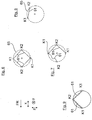
- FIG. 1 For the sake of easier understanding of the invention, a roughly schematic representation of a wheel carrier 1 of a vehicle wheel 13 not encompassed by the invention and known from the prior art is shown.
- the wheel carrier 1 has a carrier part 3, in which a wheel flange 5 with its hub portion 7 is rotatably mounted in a wheel bearing 12. At the wheel flange 5, a brake disk 11 and a vehicle wheel 13 is mounted with its rim. The brake disk 11 is part of a brake system together with a brake caliper 15 mounted on the carrier part 3.
- the wheel carrier 1, a guide member 17, on which in the Fig. 1 by way of example a link 19 of the suspension is articulated.
- two rotary parts 21, 23 are provided as adjusting elements.
- the rotary member 21 is rotatably connected to the support member 3 to form a rotary member axis 20 at a bearing 32.
- the rotating part 23 is connected to the guide member 17 to form the axis of rotation 22 at a bearing 35.
- the two rotating parts 21, 23 connected via planar inclined surfaces 25, 27 to each other in slide bearing and a rotation axis 24 rotatable with each other.
- the axis of rotation 24 is in the Fig. 1 aligned perpendicular to the inclined surfaces 25, 27 and at a defined angle to the axis of rotation 22 of the axle-side rotary member 23 inclined.
- the rotary member axis 20 is identical in position to the wheel axle.
- the rotary member 21 may not be arranged coaxially with the wheel axle, but the rotary member axis 20 and the wheel axle may be inclined to each other.
- an electric servomotor 29 is provided in each case, which is connected to the rotary parts 21, 23 via gear drives 30 driven.
- the two rotating parts 21, 23 are rotated in the same direction or in opposite directions in both directions of rotation, whereby the support member 3 relative to the guide member 17 is a pivoting movement or wobble about a Momentanpol MP ( Fig. 2 to 5 ) and thus changes the toe angle and / or the camber angle of the vehicle wheel 13 accordingly.
- FIG. 2 the wheel carrier 1 according to the invention is shown.
- the two rotating parts 21, 23 are no longer on plane inclined surfaces 25, 27 in abutment to define the inclined axis of rotation 24, but at a pivot bearing point 31st
- the wheel bearing 12 is no longer directly integrated in the wheel-side support member 3, but rather directly within the wheel-side rotary member 21.
- the outer races and the inner bearings of the wheel bearing 12 are purely exemplary incorporated directly in the inner circumference of the wheel-side rotary member 21 and directly in the outer periphery of the hub portion 7 of the wheel flange 5. Accordingly serves in the Fig. 2 On the outer circumference of the wheel-side rotary member 21 in the vehicle transverse direction y outside the support member 3 via a bearing 43 radially outwardly supported on the wheel-side rotary member 21.
- the bearing 43 must be designed so that tilting moments can be absorbed.
- the wheel bearing 12 can be made removable, with a radially outer bearing housing, which is removable, that is, for example, in a press fit or by screwing, is mounted on the inner circumference of the rotary member 21, and / or with a radially inner bearing housing, which is mountable on the outer circumference of the wheel hub 5.
- the bearing point 43 and the pivot bearing point 31 are formed purely by way of example on axially opposite sides of the rotary part 21, with a gear section 47 being positioned therebetween, which is part of the gear drive 30 (FIG. Fig. 1 ).
- the axle-side guide member 17 is - analogous to the wheel-side support member 3 - supported on a rotary bearing 51 radially outward on the axle-side rotary member 23.
- the gear portion 55 of the axle-side rotary member 23 is positioned in an annular space 57 which is bounded in the vehicle transverse direction y outwardly by the pivot bearing 51 and is bounded inwardly by a ring seal 59 which is disposed between the guide member 17 and the axle-side rotary member 23.
- the invention carries the wheel-side support member 3 - in addition to, for example, an electronic parking brake - only the caliper 15 and the drive motor 29 for the wheel-side rotary member 21, but no longer the wheel bearing 12.
- This is specifically arranged between the support member 3 and the wheel-side rotary member 21 Pivot bearing 43 taken from the wheel power flow.
- a coupling rod 61 mounted between the support part 3 and the guide part 17 is in the Fig. 2 .
- This acts as a torque transmission element, via the torques, in particular a braking torque and / or engine torque of the outer rotary drive 29, from the support member 3 to the guide member 17 is transferable, namely by bridging the axis and Wheel-side rotating parts 21, 23.
- the coupling rod 61 is arranged for example radially outside a circumferential rubber boot 63, which seals the rotating parts 21, 23 and their bearings dirt-tight.
- the coupling rod 61 is positioned with its articulation points K1 and K2 on the wheel-side carrier part 3 and on the axle-side guide part 17 in such a way that a directed force component F (FIG. Fig. 3 or 4 ) results, with which the wheel-side support member 3 is acted upon.
- a braking force longitudinal component F B, x acts on the vehicle wheel 13, of which in the Fig. 4 by way of example a braking force longitudinal component F B, x is highlighted.
- the braking force longitudinal component F B, x acts on the wheel center R M , which in the Fig. 4 is spaced by a lever arm from the instantaneous pole MP, whereby a longitudinal moment M B, x is generated, which presses the vehicle wheel 13 in the direction of the toe.
- the longitudinal moment M B, x is transmitted via the hub portion 7 of the wheel flange 5 and the wheel bearing 12 except for the wheel-side rotary member 21.
- moments M B, x and M B, z add up (possibly together with other, occurring during braking moments) to a total vehicle wheel M tires , which acts as a reaction torque on the rotating parts 21, 23.
- the total vehicle wheel torque M tires can, but need not necessarily be identical to the reaction torque, which acts directly on the rotary drive of the rotary parts 21, 23. Rather, it can the reaction torque also be different from the total vehicle wheel M tires . This depends, for example, on the current rotational positions of the turned parts, on the current position of the inclined plane formed between the turned parts and / or on the actuator's own translation.
- the total vehicle wheel torque M tire is converted into the directed force component F, with which the coupling rod 61 caulked during braking against the wheel-side support member 3, that is, the wheel-side support member 3 is at the wheel-side pivot point K2 of the coupling rod 61 is acted upon by the directed force component F, whereby a counter-holding torque M coupling is generated, which counteracts the total vehicle wheel M tires so that the reaction moments on the rotating parts 21, 23 are minimized.
- the exact location of the articulation points K1, K2 of the coupling rod 61 depends on the geometric conditions of the wheel carrier and can be calculated with the aid of specialist literature (such as the textbook "Joints and cardan shafts" by Schmelz, Seherr-Thoss, Aucktor).
- the positions of the articulation points K1, K2 of the coupling rod 61 can be determined so that in the complete range of movement of the vehicle wheel 13, that is, for example, in a toe angle range of ⁇ 6.5 ° and in a camber angle range between -5 ° and +2.5 °, the braking torque acting on the rotating parts 21, 23, remaining moment is as low as possible.
- the remaining moment is calculated from the Difference between the force exerted by the coupling rod 61 Jacobhaltemoment M coupling and the above-mentioned total vehicle wheel M tires , taking into account a Aktoreigenbergersburg in the operating point for the respective force component.
- the articulation points K1, K2 are their distances to the instantaneous pole MP in the spatial directions x, y, z, as shown in FIGS Fig. 5a and 5b is clarified. Accordingly, the articulation points K1, K2 are positioned in the vehicle transverse direction y with distances ⁇ y 1, ⁇ y 2 within the instantaneous center MP. In addition, the articulation points K1, K2 are positioned in the vehicle longitudinal direction x as viewed by distances ⁇ x 1 , ⁇ x 2 in front of and behind the instantaneous pole MP.
- the articulation points K1, K2 are the articulation points K1, K2 by distances .DELTA.z 1 , .DELTA.z 2 outside (ie in the Fig. 5b positioned above) of the instantaneous pole MP.
- the articulation points K1 and K2 of the coupling rod 61 viewed in the vehicle transverse direction y, not aligned in alignment one behind the other, but in the vehicle longitudinal direction x spaced apart by a distance.
- Fig. 6 to 9 are shown simplistic replacement images that illustrate other variants of the torque transmitting element 61. Accordingly, according to the Fig. 6 not only a single coupling rod, but rather a total of up to four coupling rods may be provided, which are arranged circumferentially distributed around the wheel axle and are articulated to the wheel-side and axle-side coupling points K1 and K2.
- the coupling points K1 and K2 are all located on a circular line 65, which exemplarily reproduces the outer contour of a cardan ring of a universal joint, which is considerably more space-consuming than the coupling rods, as is shown by way of example in FIG DE 10 2009 058 489 A1 between the wheel-side support member and the axle-side guide member 17 is arranged.
- a total of three coupling rods 61 are provided, of which two coupling rods 61 extend in a straight line, while the third coupling rod 61, for example, due to space constraints has an S-shock.
- the torque transmitting element 61 is not formed by a coupling rod, but rather by coupling members, which can be claimed only on train, for example, chains or drawstrings.
Landscapes
- Engineering & Computer Science (AREA)
- Mechanical Engineering (AREA)
- Chemical & Material Sciences (AREA)
- Combustion & Propulsion (AREA)
- Transportation (AREA)
- Vehicle Body Suspensions (AREA)
- Braking Arrangements (AREA)
Description
Die Erfindung betrifft eine Vorrichtung zum Verstellen von Sturz und/oder Spur eines Kraftfahrzeugrades nach dem Oberbegriff des Patentanspruches 1.The invention relates to a device for adjusting the camber and / or track of a motor vehicle wheel according to the preamble of
Aus der
Bei einem Bremsvorgang werden die von der Bremsanlage generierten Bremskräfte und -momente über den Radträger zum Fahrzeugaufbau geleitet, wodurch die Gefahr besteht, dass das Sturz- und/oder Spurverhalten des Radträgers unbeabsichtigt beeinflusst wird. So ist beim Bremsvorgang das radseitige Trägerteil über den in Bremseingriff befindlichen Bremssattel mit einem Bremsmoment beaufschlagt. Um eine Einleitung des Bremsmomentes in die beiden Drehteile zu vermeiden, ist das radseitige Trägerteil in der
Zusätzlich wirken beim Bremsvorgang Kräfte und Momente auf das Fahrzeugrad, wodurch die Gefahr besteht, dass das Sturz- und/oder Spurverhalten des Radträgers unbeabsichtigt beeinflusst wird. Beispielhaft sei eine auf das Fahrzeugrad wirkende Bremskraft-Längskomponente genannt, mit der ein am Fahrzeugrad angreifendes Längsmoment erzeugt wird, das das Fahrzeugrad in Richtung Nachspur drückt. Zudem sei der Bremsnickausgleich hervorgehoben. Ein solcher Bremsnickausgleich ergibt sich, wenn das abgebremste Fahrzeug aufgrund seiner Massenträgheit eine Bewegung um die Fahrzeug-Querachse, das heißt ein Abtauchen der Frontpartie, ausführt. In diesem Fall greift am Fahrzeugrad eine Bremskraft-Vertikalkomponente an, mit der ein auf das Fahrzeugrad wirkendes Vertikalmoment erzeugt wird, das zu einer Sturzmomentänderung am Aktor der Drehteile führt.In addition, forces and torques act on the vehicle wheel during the braking process, whereby there is the danger that the camber and / or toe behavior of the wheel carrier will be influenced unintentionally. By way of example, a braking force longitudinal component acting on the vehicle wheel is mentioned, with which a longitudinal torque acting on the vehicle wheel is generated, which presses the vehicle wheel in the direction of the toe. In addition, the brake-knee compensation is highlighted. Such Bremsnickausgleich results when the braked vehicle due to its inertia movement about the vehicle transverse axis, that is, a descent of the front end performs. In this case, the vehicle wheel engages a braking force-vertical component, with which a force acting on the vehicle wheel vertical torque is generated, which leads to a fall momentum change at the actuator of the rotating parts.
Diese exemplarisch hervorgehobenen Vertikal- und Längsmomente summieren sich (gegebenenfalls zusammen mit noch anderen, beim Bremsvorgang auftretenden Momenten) zu einem Gesamt-Fahrzeugradmoment, das als ein Reaktionsmoment auf die Drehteile einwirkt. Das Reaktionsmoment beaufschlagt unmittelbar den Drehantrieb der Drehteile und muß nicht zwangsläufig identisch mit dem Gesamt-Fahrzeugradmoment sein. Vielmehr kann das Reaktionsmoment auch vom Gesamt-Fahrzeugradmoment unterschiedlich sein, und zwar in Abhängigkeit von unter anderem den aktuellen Drehpositionen der Drehteile und/oder von der aktuellen Lage der zwischen den Drehteilen gebildeten Schrägebene.These exemplary emphasized vertical and longitudinal moments add up (possibly together with still other, occurring during the braking process moments) to a total vehicle wheel, which acts as a reaction torque on the rotating parts. The reaction torque acts directly on the rotary drive of the rotating parts and does not necessarily have to be identical to the total vehicle wheel torque. Rather, the reaction torque may also be different from the total vehicle wheel torque, depending on, inter alia, the current rotational positions of the rotary parts and / or on the current position of the inclined plane formed between the rotary parts.
Damit das auf die Drehteile einwirkende Gesamt-Fahrzeugradmoment nicht zu einer unbeabsichtigten Drehverstellung der Drehteile führt, muss im Stand der Technik der Drehantrieb des radseitigen und des achsseitigen Drehteils ein entgegengesetztes Kompensationsmoment bereitstellen. Hierzu sind entsprechende bauliche Maßnahmen am Drehantrieb vorzunehmen, um diesen zum Beispiel selbsthemmend auszuführen, oder steuerungstechnische Maßnahmen, um durch Ansteuerung des Drehantriebs das Kompensationsmoment zu erzeugen.So that the total vehicle wheel torque acting on the turned parts does not lead to an unintentional rotational adjustment of the turned parts, must in the state of Technology of the rotary drive of the wheel-side and the axle-side rotary part provide an opposite compensation torque. For this purpose, appropriate structural measures are to be made on the rotary drive in order to perform this, for example, self-locking, or control engineering measures to generate by controlling the rotary drive, the compensation torque.
Aus der
Die Aufgabe der Erfindung besteht darin, eine Vorrichtung bereitzustellen, bei der selbsttätig ohne Eingriff des Drehantriebes der Drehteile beim Bremsvorgang eine Sturz- und/oder Spuränderung in einfacher Weise reduzierbar ist.The object of the invention is to provide a device in which automatically without intervention of the rotary drive of the rotary parts during braking a fall and / or lane change is reduced in a simple manner.
Die Aufgabe ist durch die Merkmale des Patentanspruches 1 gelöst. Bevorzugte Weiterbildungen der Erfindung sind in den abhängigen Ansprüchen offenbart.The object is solved by the features of
Efindungsgemäß ist die Drehmomentbrücke zwischen dem radseitigen Trägerteil und dem achsseitigen Führungsteil als ein Drehmomentübertragungselement ausgelegt, das bei der Abstützung des mit dem Bremsmoment beaufschlagten Trägerteils am Führungsteil eine Kraftkomponente erzeugt, mit der das radseitige Trägerteil beim Bremsvorgang beaufschlagt wird. Das Drehmomentübertragungselement wandelt somit das Bremsmoment in die Kraftkomponente um. Mittels der Kraftkomponente kann ein unbeabsichtigtes Lenken des radseitigen Trägerteils aufgrund kinematischer Eigenschaften des Radträgers beim Bremsvorgang verhindert werden, was ansonsten zu einer unbeabsichtigten Sturz- oder Spuränderung des Fahrzeugrades beim Bremsvorgang führen würde.Efindungsgemäß the torque bridge between the wheel-side support member and the axle-side guide member is designed as a torque transmitting element that generates a force component in the support of the acted upon by the brake torque support member on the guide member, with which the wheel-side support member is acted upon braking. The torque transmitting element thus converts the braking torque into the force component. By means of the force component, unintentional steering of the wheel-side carrier part due to kinematic properties of the wheel carrier during braking can be prevented, which otherwise leads to an unintentional Crash or lane change of the vehicle wheel would lead to braking.
Das Drehmomentübertragungselement ist zumindest eine Koppelstange, die sowohl auf Zug als auch auf Druck beanspruchbar ist. Die Koppelstange ist jeweils an einer radseitigen Anlenkstelle am radseitigen Trägerteil und an einer achsseitigen Anlenkstelle um achsseitigen Führungsteil angelenkt. Herkömmliche Drehmomentbrücken, etwa ein Kardangelenk oder ein Metallbalg, sind alleine im Hinblick auf eine einwandfreie Bremsmoment-Abstützung ausgelegt, das heißt torsionssteif mit Bezug auf die Radachse, jedoch in der Fahrzeugquerrichtung ausreichend nachgiebig, um die Taumelbewegung des radseitigen Drehteils mit daran gekoppeltem Trägerteil nicht zu beeinträchtigen. Eine solche Drehmomentbrücke ist jedoch nicht in der Lage, die oben erwähnte gerichtete Kraftkomponente auf das radseitige Trägerteil auszuüben.The torque transmission element is at least one coupling rod, which can be claimed both on train and on pressure. The coupling rod is articulated in each case at a wheel-side articulation point on the wheel-side carrier part and on an axle-side articulation point about the axle-side guide part. Conventional torque bridges, such as a universal joint or a metal bellows, are designed solely for proper braking torque support, that is torsionally stiff with respect to the wheel axle, but sufficiently yielding in the vehicle transverse direction, not to the tumbling motion of the wheel-side rotary member coupled thereto carrier part affect. However, such a torque bridge is not able to exert the above-mentioned directed force component on the wheel-side support member.
Die Koppelstange ist dabei so zwischen dem radseitigen Trägerteil und dem achsseitigen Führungsteil angeordnet, dass diese unter Ausübung des Bremsmomentes dazwischen verstemmt wird, das heißt die Koppelstange beaufschlagt an ihrer radseitigen Anlenkstelle das radseitige Trägerteil mit der gerichteten Kraftkomponente. Die rad- und achsseitigen Anlenkstellen des Drehmomentübertragungselements, das heißt der Koppelstange, sind bevorzugt nicht in der Fahrzeugquerrichtung in Flucht zueinander ausgerichtet, sondern rein beispielhaft vielmehr in der Fahrzeuglängsrichtung um einen Längsversatz voneinander beabstandet. Auf diese Weise wird beim Bremsvorgang die oben beschriebene Stemmwirkung erreicht, bei der die Koppelstange das Trägerteil mit der gerichteten Kraftkomponente beaufschlagt, mit der unter anderem eine Sturzmomentänderung reduziert wird, die aus dem Bremsnickausgleich resultiert.The coupling rod is arranged between the wheel-side support member and the axle-side guide member, that this is caulked in the exercise of the braking torque therebetween, that is, the coupling rod acted on its wheel-side articulation point, the wheel-side support member with the directed force component. The wheel and axle-side articulation points of the torque transmitting element, that is, the coupling rod are preferably not aligned in the vehicle transverse direction in alignment with each other, but purely by way of example rather spaced apart in the vehicle longitudinal direction by a longitudinal offset. In this way, the above-described Stemmwirkung is achieved in the braking operation, in which the coupling rod acts on the carrier part with the directed force component, with the inter alia, a fall momentum change is reduced, resulting from the Bremsnickausgleich.
Die genaue Lage der Anlenkstellen des Drehmomentübertragungselements hängt von den geometrischen Gegebenheiten des Radträgers ab. In Kenntnis der Erfindung kann der Fachmann unter Zuhilfenahme der Fachliteratur (etwa das Fachbuch "Gelenke und Gelenkwellen" von Schmelz, Seherr-Thoss, Aucktor) die genaue Lage der Anlenkstellen unmittelbar und eindeutig berechnen. Beispielhaft können die Positionen der Anlenkstellen K1, K2 des Drehmomentübertragungselements so bestimmt sein, dass im kompletten Bewegungsraum des Fahrzeugrads, das heißt zum Beispiel in einem Spurwinkelbereich von ± 6,5° und in einem Sturzwinkelbereich zwischen -5° und +2,5°, das beim Bremsvorgang, auf die Drehteile einwirkende, verbleibende Reaktionsmoment möglichst gering ist. Das verbleibende Moment berechnet sich aus der Differenz zwischen dem von dem Drehmomentübertragungselement ausgeübten Gegenhaltemoment und dem oben erwähnten Gesamt-Fahrzeugradmoment.The exact location of the articulation points of the torque transmitting element depends on the geometric conditions of the wheel carrier. With knowledge of the invention, the skilled person with the aid of specialist literature (such as the textbook "joints and propeller shafts" of Schmelz, Seherr-Thoss, Aucktor) calculate the exact location of the articulation points directly and clearly. By way of example, the positions of the articulation points K1, K2 of the torque transmission element can be determined such that in the complete movement space of the vehicle wheel, that is, for example in a toe angle range of ± 6.5 ° and in a camber angle range between -5 ° and + 2.5 °, the lowest possible residual reaction torque acting on the rotating parts during the braking process. The remaining torque is calculated from the difference between the counter-torque exerted by the torque-transmitting element and the above-mentioned total vehicle wheel torque.
Entscheidend bei der Positionierung der Anlenkstellen sind deren Abstände zum Momentanpol in den Raumrichtungen. In einer beispielhaften bevorzugten Ausführungsform können die Anlenkstellen in der Fahrzeugquerrichtung betrachtet innerhalb des Momentanpols positioniert sein. Zudem können die Anlenkstellen in der Fahrzeuglängsrichtung betrachtet vor und hinter dem Momentanpol positioniert sein. In der Fahrzeughochrichtung können die Anlenkstellen ebenfalls versetzt zum Momentanpol positioniert sein. Die Anlenkstellen können somit, in der Fahrzeugquerrichtung betrachtet, nicht in Flucht hintereinander ausgerichtet sein, sondern in der Fahrzeuglängsrichtung um einen Abstand voneinander beabstandet sein.Decisive in the positioning of the articulation points are their distances to the instantaneous center in the spatial directions. In an exemplary preferred embodiment, the articulation points may be positioned within the instantaneous center viewed in the vehicle transverse direction. In addition, viewed in the vehicle longitudinal direction, the articulation points can be positioned in front of and behind the instantaneous pole. In the vehicle vertical direction, the articulation points can also be positioned offset to the instantaneous pole. The articulation points can thus, viewed in the vehicle transverse direction, not be aligned in alignment one behind the other, but be spaced apart in the vehicle longitudinal direction by a distance.
In einer bevorzugten technischen Realisierung kann das radseitige Trägerteil des Radträgers über ein Drehlager auf dem radseitigen Drehteil abgestützt sein. Zudem kann in dem radseitigen Drehteil ein Radlager integriert sein. In dem Radlager ist ein Radnabenabschnitt eines, das Fahrzeugrad tragenden Radflansches drehbar gelagert. In diesem Fall trägt das radseitige Trägerteil nur noch den Bremssattel und gegebenenfalls den Antriebsmotor für das radseitige Drehteil. Dadurch wird die Lagerstelle zwischen dem radseitigen Drehteil und dem radseitigen Trägerteil aus dem Radkraftfluss genommen und kräftemäßig entlastet. Dies führt dazu, dass nur noch drei Lagerstellen in Serie im Radkraftfluss geschaltet sind. Die vierte Lagerstelle, das heißt das Drehlager zwischen dem radseitigen Trägerteil und dem radseitigen Drehteil, kann dagegen kleiner ausgelegt sein, da die auf dieses Drehlager einwirkenden Kräfte und Momente von zum Beispiel der Bremsanlage sehr viel geringer ausfallen. Weiterhin erhöht sich durch den Wegfall der vierten Lagerstelle aus dem Radkraftfluss die Sturzsteifigkeit des Lagerverbundes, wodurch die verbleibenden Lagerstellen bei gleichbleibender Sturzsteifigkeit wieder kleiner ausgeführt werden können. In Summe reduziert sich - im Vergleich zum Stand der Technik - der Bauraumbedarf sowie das Bauteilgewicht der Vorrichtung beträchtlich.In a preferred technical realization, the wheel-side carrier part of the wheel carrier can be supported on the wheel-side rotary part via a rotary bearing. In addition, a wheel bearing can be integrated in the wheel-side rotary part. In the wheel bearing is a hub portion of a, the vehicle wheel bearing Wheel flange rotatably mounted. In this case, the wheel-side support member carries only the caliper and optionally the drive motor for the wheel-side rotary member. As a result, the bearing between the wheel-side rotary member and the wheel-side support member is taken from the Radkraftfluss and relieved in terms of strength. As a result, only three bearing points are connected in series in the wheel power flow. The fourth bearing point, that is, the pivot bearing between the wheel-side support member and the wheel-side rotary member, however, can be made smaller, since the forces acting on this pivot bearing and moments of, for example, the brake system are much lower. Furthermore, increases by the elimination of the fourth bearing point of the Radkraftfluss the lintel stiffness of the bearing assembly, whereby the remaining bearings can be made smaller again with constant lintel stiffness. In sum, compared with the prior art, the space requirement and the component weight of the device are considerably reduced.
Bevorzugt kann das radseitige Trägerteil radial außerhalb des radseitigen Drehteils angeordnet sein, wodurch die Vorrichtung in Axialrichtung besonders kompakt gestaltet werden kann. In diesem Fall kann das Trägerteil über eine radial innere Lagermantelfläche unter Zwischenschaltung des Drehlagers auf einer radial äußeren Lagermantelfläche des radseitigen Drehteils abgestützt sein.Preferably, the wheel-side support member may be arranged radially outside of the wheel-side rotary member, whereby the device can be made particularly compact in the axial direction. In this case, the support member may be supported via a radially inner bearing jacket surface with the interposition of the pivot bearing on a radially outer bearing surface of the wheel-side rotary member.
Das achsseitige Drehteil und das radseitige Drehteil können jeweils mit einem Antriebsmotor trieblich verbunden sein. Bevorzugt können die Drehteile jeweils Bestandteile eines Zahnradtriebs sein, bei dem der Elektromotor über eine Zahnradstufe das achsseitige und/oder radseitige Drehteil antreibt. Bei gleichsinniger oder gegensinniger Verdrehung der Drehteile erfolgt eine Verschwenkung des Trägerteils um einen vorgegebenen Spur- und/oder Sturzwinkel. Eine besonders bauraumsparende Anordnung ergibt sich, wenn das radseitige Drehteil einen Zahnradabschnitt aufweist, der Bestandteil des oben erwähnten Zahnradtriebs ist und in Axialrichtung betrachtet zwischen der Trägerteil-Abstützstelle und der Schrägfläche des radseitigen Drehteils angeordnet ist.The axle-side rotary member and the wheel-side rotary member may each be drivingly connected to a drive motor. Preferably, the rotary parts can each be components of a gear drive, in which the electric motor drives the axle-side and / or wheel-side rotary part via a gear stage. In the same direction or in opposite directions rotation of the rotating parts, a pivoting of the support member to a predetermined track and / or camber angle. A particularly space-saving arrangement results when the wheel-side rotary member has a gear portion, which is part of the above-mentioned gear drive and is arranged in the axial direction between the support part support point and the inclined surface of the wheel-side rotary member.
Um eine fertigungstechnisch einfache Einbindung der Vorrichtung in eine herkömmliche Radaufhängung zu ermöglichen, kann der Radträger ein achsseitiges Führungsteil aufweisen. Am achsseitigen Führungsteil können die Lenker der Radaufhängung des Fahrzeugs angelenkt sein. Zudem kann das Führungsteil bewegungsentkoppelt, das heißt über ein Drehlager auf dem achsseitigen Drehteil abgestützt sein. Das Führungsteil kann, ähnlich wie das radseitige Trägerteil, radial außerhalb des achsseitigen Drehteils angeordnet sein. In diesem Fall kann das Führungsteil über eine radial innere Lagerstelle auf dem achsseitigen Drehteil abgestützt sein.In order to enable a manufacturing technology simple integration of the device in a conventional suspension, the wheel carrier may have an axle-side guide member. On the axle-side guide part, the handlebars of the suspension of the vehicle can be articulated. In addition, the guide member can be decoupled motion, that is, be supported on the axle-side rotary member via a pivot bearing. The guide member may, similar to the wheel-side support member, be arranged radially outside of the axle-side rotary member. In this case, the guide member may be supported on the axle-side rotary member via a radially inner bearing.
Die Erfindung und ihre vorteilhaften Aus- und Weiterbildungen sowie deren Vorteile werden nachfolgend anhand von Zeichnungen näher erläutert.The invention and its advantageous embodiments and further developments and advantages thereof are explained in more detail below with reference to drawings.
Es zeigen:
- Fig. 1
- eine Prinzipdarstellung der Vorrichtung zum Verstellen von Spur- und Sturzwinkel eines Kraftfahrzeugrades;
- Fig. 2
- in einem Halbschnitt die obere Hälfte der Vorrichtung in einer gegenständlichen Ausführung;
- Fig. 3
- im Vollschnitt die Vorrichtung mit angebautem Fahrzeugrad;
- Fig. 4
- eine Schnittdarstellung entlang der Schnittebene I-I aus der
Fig. 3 ; - Fig. 5a und 5b
- den Radträger jeweils in einer Ansicht von oben und in einer Ansicht von hinten; und
- Fig. 6
bis 9 - jeweils Prinzipdarstellungen unterschiedlicher Koppelanordnungen zwischen dem radseitigen Trägerteil und dem achsseitigen Führungsteil des Radträgers, wobei die in der
Fig. 9 gezeigte Prinzipdarstellung nicht von der Erfindung umfasst ist.
- Fig. 1
- a schematic diagram of the device for adjusting the toe and camber angle of a motor vehicle wheel;
- Fig. 2
- in a half section, the upper half of the device in an objective embodiment;
- Fig. 3
- in full section, the device with attached vehicle wheel;
- Fig. 4
- a sectional view along the section plane II of the
Fig. 3 ; - Fig. 5a and 5b
- the wheel carrier in each case in a view from above and in a view from behind; and
- Fig. 6 to 9
- respectively schematic representations of different coupling arrangements between the wheel-side support member and the axle-side guide member of the wheel carrier, wherein in the
Fig. 9 shown schematic representation is not included in the invention.
In der
Der Radträger 1 weist ein Trägerteil 3 auf, in dem ein Radflansch 5 mit seinem Nabenabschnitt 7 drehbar in einem Radlager 12 gelagert ist. Am Radflansch 5 ist eine Bremsscheibe 11 sowie ein Fahrzeugrad 13 mit seiner Felge montiert. Die Bremsscheibe 11 ist zusammen mit einem am Trägerteil 3 montierten Bremssattel 15 Bestandteil einer Bremsanlage. Durch den Radträger 1 hindurch ist eine, das Fahrzeugrad 13 antreibende Gelenkwelle geführt, an dessen Gleichlaufgelenk (nur in den
Ferner weist der Radträger 1 ein Führungsteil 17 auf, an dem in der
In der
Sowohl am Trägerteil 3 als auch am Führungsteil 17 ist jeweils ein elektrischer Stellmotor 29 vorgesehen, der mit den Drehteilen 21, 23 über Zahnradtriebe 30 trieblich verbunden ist. Mittels der Stellmotoren 29 können die beiden Drehteile 21, 23 gleichsinnig oder gegensinnig in beide Drehrichtungen verdreht werden, wodurch das Trägerteil 3 relativ zum Führungsteil 17 eine Schwenkbewegung oder Taumelbewegung um einen Momentanpol MP (
In der
In der
Zudem ist in der
In Abkehr von der
Wie aus der
Das achsseitige Führungsteil 17 ist - analog zum radseitigen Trägerteil 3 - an einem Drehlager 51 radial außen auf dem achsseitigen Drehteil 23 abgestützt. Im weiteren Verlauf in der Fahrzeugquerrichtung y nach innen ist am Außenumfang des achsseitigen Drehteils 23 beispielhaft ein weiterer Zahnradabschnitt 55 angeformt, der ebenfalls Bestandteil des Zahnradtriebs 30 ist. Der Zahnradabschnitt 55 des achsseitigen Drehteils 23 ist in einem Ringraum 57 positioniert, der in der Fahrzeugquerrichtung y nach außen durch das Drehlager 51 begrenzt ist und nach innen durch eine Ringdichtung 59 begrenzt ist, die zwischen dem Führungsteil 17 und dem achsseitigen Drehteil 23 angeordnet ist.The axle-
Erfindungsgemäß trägt das radseitige Trägerteil 3 - neben zum Beispiel einer elektronischen Parkbremse - nur noch den Bremssattel 15 sowie den Antriebsmotor 29 für das radseitige Drehteil 21, jedoch nicht mehr das Radlager 12. Dadurch wird speziell das zwischen dem Trägerteil 3 und dem radseitigen Drehteil 21 angeordnete Drehlager 43 aus dem Radkraftfluss genommen. Dies führt dazu, dass bezogen auf die auftretenden Radkräfte nur noch drei Lagerstellen in Serie geschaltet sind, und zwar das Radlager 12, das Drehlager 31 sowie das Stützlager 51, nicht jedoch die Lagerstelle 43, an der das Trägerteil 3 auf dem radseitigen Drehteil 21 abgestützt ist. Von daher kann die auf dem radseitigen Drehteil 21 sitzende Lagerstelle 43 wesentlich kleiner ausgelegt sein, da die dort einwirkenden Radkräfte und -momente sehr viel geringer ausfallen. Durch Wegfall der Lagerstelle 43 aus dem Radkraftfluss erhöht sich zudem die Sturzsteifigkeit des Lagerverbundes, wodurch die verbleibenden Lager, das heißt das Radlager 12, das Drehlager 31 sowie das Stützlager 51, bei - im Vergleich zum Stand der Technik - gleichbleibender Sturzsteifigkeit kleiner ausgelegt werden können.According to the invention carries the wheel-side support member 3 - in addition to, for example, an electronic parking brake - only the
Zwischen dem Trägerteil 3 und dem Führungsteil 17 ist in der
Die Koppelstange 61 ist mit ihren Anlenkstellen K1 und K2 so am radseitigen Trägerteil 3 und am achsseitigen Führungsteil 17 positioniert, dass sich bei einem Bremsvorgang eine gerichtete Kraftkomponente F (
Beim Bremsvorgang wirken Kräfte und Momente auf das Fahrzeugrad 13, von denen in der
Zudem greift beim Bremsvorgang am Fahrzeugrad 13 (Hinterrad) aufgrund des Bremsnickausgleichs eine in der
Diese exemplarisch in den
Damit das auf die Drehteile 21, 23 einwirkende Reaktionsmoment nicht zu einer unbeabsichtigten Drehbewegung der Drehteile 21, 23 führt, erfolgt im Stand der Technik eine dazu korrespondierende Gegensteuerung des Zahnradtriebes 30 des radseitigen und/oder des achsseitigen Drehteils 21,23.So that the reaction torque acting on the
Im Unterschied dazu wird erfindungsgemäß beim Bremsvorgang mittels der Koppelstange 61 das Gesamt-Fahrzeugradmoment MReifen in die gerichtete Kraftkomponente F umgewandelt, mit der sich die Koppelstange 61 beim Bremsvorgang gegen das radseitige Trägerteil 3 verstemmt, das heißt das radseitige Trägerteil 3 wird an der radseitigen Anlenkstelle K2 der Koppelstange 61 mit der gerichteten Kraftkomponente F beaufschlagt, wodurch ein Gegenhaltemoment MKoppel erzeugt wird, das dem Gesamt-Fahrzeugradmoment MReifen so entgegenwirkt, dass die Reaktionsmomente auf die Drehteile 21, 23 möglichst gering sind.In contrast, according to the invention during braking by means of the
Die genaue Lage der Anlenkstellen K1, K2 der Koppelstange 61 hängt von den geometrischen Gegebenheiten des Radträgers ab und kann unter Zuhilfenahme der Fachliteratur (etwa das Fachbuch "Gelenke und Gelenkwellen" von Schmelz, Seherr-Thoss, Aucktor) berechnet werden. Beispielhaft können die Positionen der Anlenkstellen K1, K2 der Koppelstange 61 so bestimmt werden, dass im kompletten Bewegungsraum des Fahrzeugrads 13, das heißt zum Beispiel in einem Spurwinkelbereich von ± 6,5° und in einem Sturzwinkelbereich zwischen -5° und +2,5°, das beim Bremsvorgang auf die Drehteile 21, 23 einwirkende, verbleibende Moment möglichst gering ist. Das verbleibende Moment berechnet sich aus der Differenz zwischen dem von der Koppelstange 61 ausgeübten Gegenhaltemoment MKoppel und dem oben erwähnten Gesamt-Fahrzeugradmoment MReifen, und zwar unter Berücksichtigung einer Aktoreigenübersetzung im Betriebspunkt für die jeweilige Kraftkomponente.The exact location of the articulation points K1, K2 of the
Entscheidend bei der Positionierung der Koppelstangen-Anlenkstellen K1, K2 sind deren Abstände zum Momentanpol MP in den Raumrichtungen x, y, z, wie es in den
In den folgenden
In der
Claims (10)
- Device for adjusting the camber and/or track of a vehicle wheel (13) of a motor vehicle, comprising a wheel carrier (1), which consists of multiple parts with a wheel-side carrier part (3) and an axle-side guide part (17) and rotary parts (21, 23) arranged in between, which are supported rotatably relative to one another on a common bearing point (31) about an axis of rotation (24), about which the wheel-side rotary part (21) can be pivoted for adjusting the track or camber of the vehicle wheel (13) about a wobble point (MP), wherein the wheel-side carrier part (3) supports a brake calliper (15) cooperating with a brake disc (11) of the vehicle wheel (13), and wherein the wheel-side carrier part (3), to which braking torque is applied during a braking process, can be supported by a torque bridge (61) on the axle-side guide part (17), wherein the torque bridge (61) is configured as a torque transmission element, which on the support of the carrier part (3), to which braking torque is applied, produces a directed force component (F) with which the wheel-side carrier part (3) can be charged, characterised in that the torque transmission element (61) is at least one coupling bar, which can be subjected to tensile and pressure forces, and in that the coupling bar can be attached respectively onto a wheel-side attachment point (K2) on the wheel-side carrier part (3) and onto an axle-side attachment point (K1) on the axle-side guide part (17).
- Device according to claim 1, characterised in that the attachment points (K1, K2) of the torque transmission element (61) are positioned so that the torque transmission element (61) can be caulked between the carrier part (3) and the guide part (17).
- Device according to claim 1 or 2, characterised in that during the braking process the torque transmission element (61) generates a counter moment (MKoppel), by means of which the reaction moment resulting from a total vehicle wheel moment (MReifen) and conducted from the vehicle wheel (13) to the rotary parts (21, 23) is reducible.
- Device according to claim 3, characterised in that the total vehicle wheel moment (MReifen) consists in particular of a longitudinal moment (MB,x), which is produced by a braking force longitudinal component (FB,x) acting on the vehicle wheel centre (RM), and a vertical moment (MB,z) acting on the vehicle wheel (13), which is produced by brake pitching compensation.
- Device according to any of the preceding claims, characterised in that the wheel centre (RM) of the vehicle wheel (13) and the wobble point and instantaneous centre of rotation (MP) are spaced apart from one another by lever arm.
- Device according to any of the preceding claims, characterised in that the attachment points (K1, K2) of the torque transmission element (61) are spaced apart from the instantaneous centre of rotation (MP) in spatial directions (x, y, z).
- Device according to any of the preceding claims, characterised in that the attachment points (K1, K2) of the torque transmission element (61) as viewed in vehicle transverse direction (y) are offset by respective distances (Δy1, Δy2) from the instantaneous centre of rotation (MP) towards the interior of the vehicle, and/or in that the attachment points (K1, K2) as viewed in the vehicle longitudinal direction (x) are positioned before and behind the instantaneous centre of rotation (MP) by respective distances (Δx1, Δx2), and/or in that the attachment points (K1, K2) are offset from the instantaneous centre of rotation (MP) in vehicle vertical direction (z) by respective distances (Δz1, Δz2).
- Device according to any of the preceding claims, characterised in that a wheel bearing (12) is integrated into the wheel-side rotary part (21), in which wheel bearing a wheel hub section (7) of a wheel flange (5) supporting the vehicle wheel (13) is rotatably mounted, and/or in that the carrier part (3) is supported by a bearing point (43) on the wheel-side rotary part (21).
- Device according to claim 8, characterised in that the carrier part (3) is arranged radially outside the wheel-side rotary part (21), and in that in particular the carrier part (3) is supported by a radially inner bearing point (43) on the wheel-side rotary part (21).
- Device according to claim 8 or 9, characterised in that the wheel bearing (12) is configured to be detachable, and comprising a radially inner bearing housing and a radially outer bearing housing, which can be mounted to be detachable, i.e. for example in a press-fit or by a screw connection, on an outer circumference of the wheel hub (5) or on an inner circumference of the rotary part (21), or in that the wheel-side rotary part (21) directly forms the radially outer bearing housing of the wheel bearing (12), and in that radially inside the rotary part (21) forming the outer bearing housing a wheel hub section (7) of a wheel flange (5) supporting the vehicle wheel (13) is rotatably mounted.
Applications Claiming Priority (2)
| Application Number | Priority Date | Filing Date | Title |
|---|---|---|---|
| DE102014011110.5A DE102014011110B4 (en) | 2014-07-26 | 2014-07-26 | Device for adjusting the camber and / or toe of a vehicle wheel with a torque transmission element |
| PCT/EP2015/001256 WO2016015801A1 (en) | 2014-07-26 | 2015-06-22 | Device for adjusting camber and/or track of a vehicle wheel |
Publications (2)
| Publication Number | Publication Date |
|---|---|
| EP3172071A1 EP3172071A1 (en) | 2017-05-31 |
| EP3172071B1 true EP3172071B1 (en) | 2018-06-06 |
Family
ID=53434297
Family Applications (1)
| Application Number | Title | Priority Date | Filing Date |
|---|---|---|---|
| EP15730067.4A Not-in-force EP3172071B1 (en) | 2014-07-26 | 2015-06-22 | Device for adjusting camber and/or track of a vehicle wheel |
Country Status (5)
| Country | Link |
|---|---|
| US (1) | US10286954B2 (en) |
| EP (1) | EP3172071B1 (en) |
| CN (1) | CN106573521B (en) |
| DE (1) | DE102014011110B4 (en) |
| WO (1) | WO2016015801A1 (en) |
Families Citing this family (3)
| Publication number | Priority date | Publication date | Assignee | Title |
|---|---|---|---|---|
| DE102014011193B4 (en) * | 2014-07-26 | 2021-03-18 | Audi Ag | Device for adjusting the camber and / or toe of a vehicle wheel with braking torque support |
| DE102014011194B4 (en) * | 2014-07-26 | 2020-12-10 | Audi Ag | Wheel carrier for a two-lane motor vehicle with rotation angle stops for toe / camber adjustment |
| JP6505842B2 (en) * | 2015-07-30 | 2019-04-24 | 本田技研工業株式会社 | vehicle |
Family Cites Families (31)
| Publication number | Priority date | Publication date | Assignee | Title |
|---|---|---|---|---|
| DE3928135A1 (en) * | 1988-08-31 | 1990-03-01 | Volkswagen Ag | Wheel suspension for motor vehicle - has wheel hub spherical connection to wheel support adjustable in dependence on car operation parameters |
| FR2872452B1 (en) * | 2004-07-02 | 2006-09-22 | Michelin Soc Tech | SUSPENSION DEVICE FOR MOTOR VEHICLE |
| DE102004049296A1 (en) * | 2004-10-09 | 2006-04-13 | Bayerische Motoren Werke Ag | Non-driven wheels for vehicle, comprising arrangement of two rings for adjusting of camber |
| DE102006061975B4 (en) * | 2006-12-21 | 2008-11-20 | Zf Friedrichshafen Ag | Arm |
| DE102008048568A1 (en) * | 2008-09-23 | 2010-03-25 | Audi Ag | Steering device for a motor vehicle |
| DE102008048567A1 (en) | 2008-09-23 | 2010-03-25 | Audi Ag | Device for adjusting a wheel of a suspension |
| DE102009006903A1 (en) * | 2009-01-30 | 2010-08-05 | Audi Ag | Device for adjusting the camber and / or track of the wheels of wheel suspensions |
| DE102009021093A1 (en) | 2009-05-13 | 2010-11-18 | Audi Ag | Wheel suspension for a motor vehicle |
| DE102009021477A1 (en) | 2009-05-15 | 2010-11-18 | Audi Ag | Device for adjusting camber and / or track |
| DE102009025227A1 (en) * | 2009-06-17 | 2010-12-30 | Audi Ag | Suspension for the rear wheels of motor vehicles |
| DE102009025586A1 (en) * | 2009-06-19 | 2010-12-23 | Audi Ag | Device for adjusting the camber and / or track of the wheels of a wheel suspension |
| DE102009038423A1 (en) * | 2009-08-21 | 2011-03-10 | Audi Ag | Device for adjusting camber and / or track |
| DE102009058490A1 (en) | 2009-12-16 | 2011-06-22 | Audi Ag, 85057 | Device for adjusting the camber and / or track of the wheels of wheel suspensions |
| DE102009058489A1 (en) * | 2009-12-16 | 2011-06-22 | Audi Ag, 85057 | Device for adjusting the camber and / or track of the wheels of motor vehicles |
| DE102010007994A1 (en) | 2010-02-15 | 2011-08-18 | Audi Ag, 85057 | Wheel suspension for a motor vehicle |
| DE102010032073A1 (en) | 2010-07-23 | 2012-01-26 | Audi Ag | Method for operating a mechatronic suspension device of a motor vehicle |
| DE102010050474B4 (en) | 2010-11-04 | 2013-05-08 | Audi Ag | Method for determining the drawbar length of a trailer of a towing vehicle and use of this method |
| DE102010052546A1 (en) | 2010-11-25 | 2012-05-31 | Audi Ag | steering device |
| DE102011010509A1 (en) | 2011-02-07 | 2012-08-09 | Audi Ag | vehicle |
| US20130099455A1 (en) | 2011-04-06 | 2013-04-25 | Audi Ag | Roll stabilizer for installation to a wheel suspension of a motor vehicle |
| DE102011016535B3 (en) | 2011-04-08 | 2012-05-10 | Audi Ag | vehicle |
| DE102011111420B4 (en) | 2011-08-23 | 2015-11-19 | Audi Ag | Method for controlling steerable rear wheels of a motor vehicle and motor vehicle |
| DE102012011918A1 (en) | 2012-06-15 | 2013-12-19 | Audi Ag | Adjustable wheel suspension for the wheels of an axle of a motor vehicle |
| DE102012011919A1 (en) | 2012-06-15 | 2013-12-19 | Audi Ag | Adjustable wheel suspension for the wheels of an axle of a motor vehicle |
| DE102012014696B4 (en) | 2012-07-25 | 2014-02-13 | Audi Ag | Roof carrier for a motor vehicle, method for operating a control device of a motor vehicle and corresponding control device |
| DE102012020879B3 (en) | 2012-10-24 | 2014-03-13 | Audi Ag | Hydraulic brake system |
| DE102013002713B4 (en) | 2013-02-16 | 2014-08-28 | Audi Ag | A torsion bar spring arrangement for a wheel suspension of a motor vehicle |
| DE102013002714B4 (en) | 2013-02-16 | 2016-06-30 | Audi Ag | Torsion spring arrangement for a wheel suspension of a motor vehicle |
| DE102013008652B4 (en) * | 2013-05-21 | 2016-10-13 | Audi Ag | Device for the fall and / or lane adjustment of a vehicle wheel |
| DE102014009517B3 (en) | 2014-06-25 | 2015-09-17 | Audi Ag | steering system |
| DE102014109038A1 (en) * | 2014-06-27 | 2015-12-31 | Benteler Automobiltechnik Gmbh | Arm |
-
2014
- 2014-07-26 DE DE102014011110.5A patent/DE102014011110B4/en not_active Expired - Fee Related
-
2015
- 2015-06-22 US US15/329,171 patent/US10286954B2/en not_active Expired - Fee Related
- 2015-06-22 WO PCT/EP2015/001256 patent/WO2016015801A1/en active Application Filing
- 2015-06-22 CN CN201580041271.4A patent/CN106573521B/en not_active Expired - Fee Related
- 2015-06-22 EP EP15730067.4A patent/EP3172071B1/en not_active Not-in-force
Non-Patent Citations (1)
| Title |
|---|
| None * |
Also Published As
| Publication number | Publication date |
|---|---|
| US20170217492A1 (en) | 2017-08-03 |
| CN106573521B (en) | 2019-05-17 |
| WO2016015801A1 (en) | 2016-02-04 |
| DE102014011110B4 (en) | 2021-03-18 |
| DE102014011110A1 (en) | 2016-01-28 |
| US10286954B2 (en) | 2019-05-14 |
| EP3172071A1 (en) | 2017-05-31 |
| CN106573521A (en) | 2017-04-19 |
Similar Documents
| Publication | Publication Date | Title |
|---|---|---|
| EP2342117B1 (en) | Steering device for a motor vehicle | |
| EP3122613B1 (en) | Steering device | |
| EP3172068B1 (en) | Device for adjusting camber and/or toe of a vehicle wheel | |
| EP2467271B1 (en) | Device for the adjustment of camber and/or toe-in and toe-out | |
| EP3216677B1 (en) | Wheel steering assembly for motor vehicles with single wheel steering | |
| EP3172072B1 (en) | Device for adjusting camber and/or toe of a vehicle wheel | |
| EP3172071B1 (en) | Device for adjusting camber and/or track of a vehicle wheel | |
| EP2165862B1 (en) | Device for adjusting a wheel of a wheel suspension | |
| EP3172069B1 (en) | Device for adjusting camber and/or toe of a vehicle wheel | |
| EP2396183A1 (en) | Wheel suspension for motor vehicles having an actuator assigned to the wheel carrier for setting a toe and/or camber angle | |
| EP2558307B1 (en) | Wheel bearing unit of a driven vehicle wheel | |
| DE102016223360B4 (en) | Drive arrangement for a vehicle and vehicle with the drive arrangement | |
| DE2128356C3 (en) | Steering device for vehicles with regulation of side forces | |
| DE102017125605A1 (en) | Chassis with friction brake device and vehicle with the chassis | |
| DE102015113156A1 (en) | Active wheel carrier for a vehicle | |
| WO2024064982A1 (en) | Steering force module for a drivetrain test bench | |
| DE102014015062A1 (en) | Wheel suspension for a two-lane motor vehicle | |
| DE102013022208A1 (en) | Bearing arrangement for mounting a wheel hub, motor vehicle | |
| DE102010043298A1 (en) | Wheel suspension for individual wheel drive of electrically driven vehicle, particularly for steered wheel, comprises suspension element or damping element which is coupled with wheel carrier |
Legal Events
| Date | Code | Title | Description |
|---|---|---|---|
| PUAI | Public reference made under article 153(3) epc to a published international application that has entered the european phase |
Free format text: ORIGINAL CODE: 0009012 |
|
| 17P | Request for examination filed |
Effective date: 20170227 |
|
| AK | Designated contracting states |
Kind code of ref document: A1 Designated state(s): AL AT BE BG CH CY CZ DE DK EE ES FI FR GB GR HR HU IE IS IT LI LT LU LV MC MK MT NL NO PL PT RO RS SE SI SK SM TR |
|
| AX | Request for extension of the european patent |
Extension state: BA ME |
|
| DAV | Request for validation of the european patent (deleted) | ||
| DAX | Request for extension of the european patent (deleted) | ||
| GRAP | Despatch of communication of intention to grant a patent |
Free format text: ORIGINAL CODE: EPIDOSNIGR1 |
|
| INTG | Intention to grant announced |
Effective date: 20180321 |
|
| GRAS | Grant fee paid |
Free format text: ORIGINAL CODE: EPIDOSNIGR3 |
|
| GRAA | (expected) grant |
Free format text: ORIGINAL CODE: 0009210 |
|
| AK | Designated contracting states |
Kind code of ref document: B1 Designated state(s): AL AT BE BG CH CY CZ DE DK EE ES FI FR GB GR HR HU IE IS IT LI LT LU LV MC MK MT NL NO PL PT RO RS SE SI SK SM TR |
|
| REG | Reference to a national code |
Ref country code: GB Ref legal event code: FG4D Free format text: NOT ENGLISH |
|
| REG | Reference to a national code |
Ref country code: CH Ref legal event code: EP Ref country code: AT Ref legal event code: REF Ref document number: 1005676 Country of ref document: AT Kind code of ref document: T Effective date: 20180615 |
|
| REG | Reference to a national code |
Ref country code: FR Ref legal event code: PLFP Year of fee payment: 4 |
|
| REG | Reference to a national code |
Ref country code: IE Ref legal event code: FG4D Free format text: LANGUAGE OF EP DOCUMENT: GERMAN |
|
| REG | Reference to a national code |
Ref country code: DE Ref legal event code: R096 Ref document number: 502015004560 Country of ref document: DE |
|
| REG | Reference to a national code |
Ref country code: NL Ref legal event code: MP Effective date: 20180606 |
|
| REG | Reference to a national code |
Ref country code: LT Ref legal event code: MG4D |
|
| PG25 | Lapsed in a contracting state [announced via postgrant information from national office to epo] |
Ref country code: NO Free format text: LAPSE BECAUSE OF FAILURE TO SUBMIT A TRANSLATION OF THE DESCRIPTION OR TO PAY THE FEE WITHIN THE PRESCRIBED TIME-LIMIT Effective date: 20180906 Ref country code: CY Free format text: LAPSE BECAUSE OF FAILURE TO SUBMIT A TRANSLATION OF THE DESCRIPTION OR TO PAY THE FEE WITHIN THE PRESCRIBED TIME-LIMIT Effective date: 20180606 Ref country code: FI Free format text: LAPSE BECAUSE OF FAILURE TO SUBMIT A TRANSLATION OF THE DESCRIPTION OR TO PAY THE FEE WITHIN THE PRESCRIBED TIME-LIMIT Effective date: 20180606 Ref country code: BG Free format text: LAPSE BECAUSE OF FAILURE TO SUBMIT A TRANSLATION OF THE DESCRIPTION OR TO PAY THE FEE WITHIN THE PRESCRIBED TIME-LIMIT Effective date: 20180906 Ref country code: SE Free format text: LAPSE BECAUSE OF FAILURE TO SUBMIT A TRANSLATION OF THE DESCRIPTION OR TO PAY THE FEE WITHIN THE PRESCRIBED TIME-LIMIT Effective date: 20180606 Ref country code: LT Free format text: LAPSE BECAUSE OF FAILURE TO SUBMIT A TRANSLATION OF THE DESCRIPTION OR TO PAY THE FEE WITHIN THE PRESCRIBED TIME-LIMIT Effective date: 20180606 Ref country code: ES Free format text: LAPSE BECAUSE OF FAILURE TO SUBMIT A TRANSLATION OF THE DESCRIPTION OR TO PAY THE FEE WITHIN THE PRESCRIBED TIME-LIMIT Effective date: 20180606 |
|
| PG25 | Lapsed in a contracting state [announced via postgrant information from national office to epo] |
Ref country code: HR Free format text: LAPSE BECAUSE OF FAILURE TO SUBMIT A TRANSLATION OF THE DESCRIPTION OR TO PAY THE FEE WITHIN THE PRESCRIBED TIME-LIMIT Effective date: 20180606 Ref country code: RS Free format text: LAPSE BECAUSE OF FAILURE TO SUBMIT A TRANSLATION OF THE DESCRIPTION OR TO PAY THE FEE WITHIN THE PRESCRIBED TIME-LIMIT Effective date: 20180606 Ref country code: LV Free format text: LAPSE BECAUSE OF FAILURE TO SUBMIT A TRANSLATION OF THE DESCRIPTION OR TO PAY THE FEE WITHIN THE PRESCRIBED TIME-LIMIT Effective date: 20180606 Ref country code: GR Free format text: LAPSE BECAUSE OF FAILURE TO SUBMIT A TRANSLATION OF THE DESCRIPTION OR TO PAY THE FEE WITHIN THE PRESCRIBED TIME-LIMIT Effective date: 20180907 |
|
| PG25 | Lapsed in a contracting state [announced via postgrant information from national office to epo] |
Ref country code: NL Free format text: LAPSE BECAUSE OF FAILURE TO SUBMIT A TRANSLATION OF THE DESCRIPTION OR TO PAY THE FEE WITHIN THE PRESCRIBED TIME-LIMIT Effective date: 20180606 |
|
| PG25 | Lapsed in a contracting state [announced via postgrant information from national office to epo] |
Ref country code: PL Free format text: LAPSE BECAUSE OF FAILURE TO SUBMIT A TRANSLATION OF THE DESCRIPTION OR TO PAY THE FEE WITHIN THE PRESCRIBED TIME-LIMIT Effective date: 20180606 Ref country code: EE Free format text: LAPSE BECAUSE OF FAILURE TO SUBMIT A TRANSLATION OF THE DESCRIPTION OR TO PAY THE FEE WITHIN THE PRESCRIBED TIME-LIMIT Effective date: 20180606 Ref country code: IS Free format text: LAPSE BECAUSE OF FAILURE TO SUBMIT A TRANSLATION OF THE DESCRIPTION OR TO PAY THE FEE WITHIN THE PRESCRIBED TIME-LIMIT Effective date: 20181006 Ref country code: RO Free format text: LAPSE BECAUSE OF FAILURE TO SUBMIT A TRANSLATION OF THE DESCRIPTION OR TO PAY THE FEE WITHIN THE PRESCRIBED TIME-LIMIT Effective date: 20180606 Ref country code: CZ Free format text: LAPSE BECAUSE OF FAILURE TO SUBMIT A TRANSLATION OF THE DESCRIPTION OR TO PAY THE FEE WITHIN THE PRESCRIBED TIME-LIMIT Effective date: 20180606 Ref country code: SK Free format text: LAPSE BECAUSE OF FAILURE TO SUBMIT A TRANSLATION OF THE DESCRIPTION OR TO PAY THE FEE WITHIN THE PRESCRIBED TIME-LIMIT Effective date: 20180606 |
|
| REG | Reference to a national code |
Ref country code: CH Ref legal event code: PL |
|
| PG25 | Lapsed in a contracting state [announced via postgrant information from national office to epo] |
Ref country code: SM Free format text: LAPSE BECAUSE OF FAILURE TO SUBMIT A TRANSLATION OF THE DESCRIPTION OR TO PAY THE FEE WITHIN THE PRESCRIBED TIME-LIMIT Effective date: 20180606 Ref country code: IT Free format text: LAPSE BECAUSE OF FAILURE TO SUBMIT A TRANSLATION OF THE DESCRIPTION OR TO PAY THE FEE WITHIN THE PRESCRIBED TIME-LIMIT Effective date: 20180606 |
|
| REG | Reference to a national code |
Ref country code: BE Ref legal event code: MM Effective date: 20180630 |
|
| REG | Reference to a national code |
Ref country code: DE Ref legal event code: R097 Ref document number: 502015004560 Country of ref document: DE |
|
| REG | Reference to a national code |
Ref country code: IE Ref legal event code: MM4A |
|
| PG25 | Lapsed in a contracting state [announced via postgrant information from national office to epo] |
Ref country code: MC Free format text: LAPSE BECAUSE OF FAILURE TO SUBMIT A TRANSLATION OF THE DESCRIPTION OR TO PAY THE FEE WITHIN THE PRESCRIBED TIME-LIMIT Effective date: 20180606 Ref country code: LU Free format text: LAPSE BECAUSE OF NON-PAYMENT OF DUE FEES Effective date: 20180622 |
|
| PLBE | No opposition filed within time limit |
Free format text: ORIGINAL CODE: 0009261 |
|
| STAA | Information on the status of an ep patent application or granted ep patent |
Free format text: STATUS: NO OPPOSITION FILED WITHIN TIME LIMIT |
|
| PG25 | Lapsed in a contracting state [announced via postgrant information from national office to epo] |
Ref country code: IE Free format text: LAPSE BECAUSE OF NON-PAYMENT OF DUE FEES Effective date: 20180622 Ref country code: LI Free format text: LAPSE BECAUSE OF NON-PAYMENT OF DUE FEES Effective date: 20180630 Ref country code: CH Free format text: LAPSE BECAUSE OF NON-PAYMENT OF DUE FEES Effective date: 20180630 |
|
| 26N | No opposition filed |
Effective date: 20190307 |
|
| PG25 | Lapsed in a contracting state [announced via postgrant information from national office to epo] |
Ref country code: SI Free format text: LAPSE BECAUSE OF FAILURE TO SUBMIT A TRANSLATION OF THE DESCRIPTION OR TO PAY THE FEE WITHIN THE PRESCRIBED TIME-LIMIT Effective date: 20180606 Ref country code: BE Free format text: LAPSE BECAUSE OF NON-PAYMENT OF DUE FEES Effective date: 20180630 Ref country code: DK Free format text: LAPSE BECAUSE OF FAILURE TO SUBMIT A TRANSLATION OF THE DESCRIPTION OR TO PAY THE FEE WITHIN THE PRESCRIBED TIME-LIMIT Effective date: 20180606 |
|
| PG25 | Lapsed in a contracting state [announced via postgrant information from national office to epo] |
Ref country code: AL Free format text: LAPSE BECAUSE OF FAILURE TO SUBMIT A TRANSLATION OF THE DESCRIPTION OR TO PAY THE FEE WITHIN THE PRESCRIBED TIME-LIMIT Effective date: 20180606 |
|
| PG25 | Lapsed in a contracting state [announced via postgrant information from national office to epo] |
Ref country code: MT Free format text: LAPSE BECAUSE OF FAILURE TO SUBMIT A TRANSLATION OF THE DESCRIPTION OR TO PAY THE FEE WITHIN THE PRESCRIBED TIME-LIMIT Effective date: 20180606 |
|
| PG25 | Lapsed in a contracting state [announced via postgrant information from national office to epo] |
Ref country code: TR Free format text: LAPSE BECAUSE OF FAILURE TO SUBMIT A TRANSLATION OF THE DESCRIPTION OR TO PAY THE FEE WITHIN THE PRESCRIBED TIME-LIMIT Effective date: 20180606 |
|
| PG25 | Lapsed in a contracting state [announced via postgrant information from national office to epo] |
Ref country code: PT Free format text: LAPSE BECAUSE OF FAILURE TO SUBMIT A TRANSLATION OF THE DESCRIPTION OR TO PAY THE FEE WITHIN THE PRESCRIBED TIME-LIMIT Effective date: 20180606 |
|
| PG25 | Lapsed in a contracting state [announced via postgrant information from national office to epo] |
Ref country code: MK Free format text: LAPSE BECAUSE OF NON-PAYMENT OF DUE FEES Effective date: 20180606 Ref country code: HU Free format text: LAPSE BECAUSE OF FAILURE TO SUBMIT A TRANSLATION OF THE DESCRIPTION OR TO PAY THE FEE WITHIN THE PRESCRIBED TIME-LIMIT; INVALID AB INITIO Effective date: 20150622 |
|
| PGFP | Annual fee paid to national office [announced via postgrant information from national office to epo] |
Ref country code: DE Payment date: 20210630 Year of fee payment: 7 Ref country code: FR Payment date: 20210630 Year of fee payment: 7 |
|
| REG | Reference to a national code |
Ref country code: AT Ref legal event code: MM01 Ref document number: 1005676 Country of ref document: AT Kind code of ref document: T Effective date: 20200622 |
|
| PGFP | Annual fee paid to national office [announced via postgrant information from national office to epo] |
Ref country code: GB Payment date: 20210624 Year of fee payment: 7 |
|
| PG25 | Lapsed in a contracting state [announced via postgrant information from national office to epo] |
Ref country code: AT Free format text: LAPSE BECAUSE OF NON-PAYMENT OF DUE FEES Effective date: 20200622 |
|
| REG | Reference to a national code |
Ref country code: DE Ref legal event code: R119 Ref document number: 502015004560 Country of ref document: DE |
|
| GBPC | Gb: european patent ceased through non-payment of renewal fee |
Effective date: 20220622 |
|
| PG25 | Lapsed in a contracting state [announced via postgrant information from national office to epo] |
Ref country code: FR Free format text: LAPSE BECAUSE OF NON-PAYMENT OF DUE FEES Effective date: 20220630 |
|
| PG25 | Lapsed in a contracting state [announced via postgrant information from national office to epo] |
Ref country code: GB Free format text: LAPSE BECAUSE OF NON-PAYMENT OF DUE FEES Effective date: 20220622 Ref country code: DE Free format text: LAPSE BECAUSE OF NON-PAYMENT OF DUE FEES Effective date: 20230103 |