EP3172011B1 - Machine for acquiring images of optical lenses and process for trimming optical lenses - Google Patents
Machine for acquiring images of optical lenses and process for trimming optical lenses Download PDFInfo
- Publication number
- EP3172011B1 EP3172011B1 EP15756199.4A EP15756199A EP3172011B1 EP 3172011 B1 EP3172011 B1 EP 3172011B1 EP 15756199 A EP15756199 A EP 15756199A EP 3172011 B1 EP3172011 B1 EP 3172011B1
- Authority
- EP
- European Patent Office
- Prior art keywords
- optical lens
- image
- reference optical
- lens
- images
- Prior art date
- Legal status (The legal status is an assumption and is not a legal conclusion. Google has not performed a legal analysis and makes no representation as to the accuracy of the status listed.)
- Active
Links
- 230000003287 optical effect Effects 0.000 title claims description 64
- 238000009966 trimming Methods 0.000 title claims description 32
- 238000000034 method Methods 0.000 title claims description 23
- 230000037230 mobility Effects 0.000 claims description 7
- 238000012512 characterization method Methods 0.000 claims description 2
- 230000000903 blocking effect Effects 0.000 description 13
- 238000004519 manufacturing process Methods 0.000 description 4
- 230000006870 function Effects 0.000 description 3
- 239000011521 glass Substances 0.000 description 3
- 238000003754 machining Methods 0.000 description 3
- 210000004907 gland Anatomy 0.000 description 2
- 230000002093 peripheral effect Effects 0.000 description 2
- 238000006073 displacement reaction Methods 0.000 description 1
- 238000005553 drilling Methods 0.000 description 1
- 230000002452 interceptive effect Effects 0.000 description 1
- 239000000463 material Substances 0.000 description 1
- 238000005259 measurement Methods 0.000 description 1
- 238000000465 moulding Methods 0.000 description 1
- 239000000523 sample Substances 0.000 description 1
- 239000013589 supplement Substances 0.000 description 1
- 238000011144 upstream manufacturing Methods 0.000 description 1
- 230000004304 visual acuity Effects 0.000 description 1
Images


Classifications
-
- B—PERFORMING OPERATIONS; TRANSPORTING
- B24—GRINDING; POLISHING
- B24B—MACHINES, DEVICES, OR PROCESSES FOR GRINDING OR POLISHING; DRESSING OR CONDITIONING OF ABRADING SURFACES; FEEDING OF GRINDING, POLISHING, OR LAPPING AGENTS
- B24B9/00—Machines or devices designed for grinding edges or bevels on work or for removing burrs; Accessories therefor
- B24B9/02—Machines or devices designed for grinding edges or bevels on work or for removing burrs; Accessories therefor characterised by a special design with respect to properties of materials specific to articles to be ground
- B24B9/06—Machines or devices designed for grinding edges or bevels on work or for removing burrs; Accessories therefor characterised by a special design with respect to properties of materials specific to articles to be ground of non-metallic inorganic material, e.g. stone, ceramics, porcelain
- B24B9/08—Machines or devices designed for grinding edges or bevels on work or for removing burrs; Accessories therefor characterised by a special design with respect to properties of materials specific to articles to be ground of non-metallic inorganic material, e.g. stone, ceramics, porcelain of glass
- B24B9/14—Machines or devices designed for grinding edges or bevels on work or for removing burrs; Accessories therefor characterised by a special design with respect to properties of materials specific to articles to be ground of non-metallic inorganic material, e.g. stone, ceramics, porcelain of glass of optical work, e.g. lenses, prisms
- B24B9/148—Machines or devices designed for grinding edges or bevels on work or for removing burrs; Accessories therefor characterised by a special design with respect to properties of materials specific to articles to be ground of non-metallic inorganic material, e.g. stone, ceramics, porcelain of glass of optical work, e.g. lenses, prisms electrically, e.g. numerically, controlled
-
- B—PERFORMING OPERATIONS; TRANSPORTING
- B24—GRINDING; POLISHING
- B24B—MACHINES, DEVICES, OR PROCESSES FOR GRINDING OR POLISHING; DRESSING OR CONDITIONING OF ABRADING SURFACES; FEEDING OF GRINDING, POLISHING, OR LAPPING AGENTS
- B24B1/00—Processes of grinding or polishing; Use of auxiliary equipment in connection with such processes
-
- B—PERFORMING OPERATIONS; TRANSPORTING
- B24—GRINDING; POLISHING
- B24B—MACHINES, DEVICES, OR PROCESSES FOR GRINDING OR POLISHING; DRESSING OR CONDITIONING OF ABRADING SURFACES; FEEDING OF GRINDING, POLISHING, OR LAPPING AGENTS
- B24B49/00—Measuring or gauging equipment for controlling the feed movement of the grinding tool or work; Arrangements of indicating or measuring equipment, e.g. for indicating the start of the grinding operation
- B24B49/12—Measuring or gauging equipment for controlling the feed movement of the grinding tool or work; Arrangements of indicating or measuring equipment, e.g. for indicating the start of the grinding operation involving optical means
-
- G—PHYSICS
- G01—MEASURING; TESTING
- G01B—MEASURING LENGTH, THICKNESS OR SIMILAR LINEAR DIMENSIONS; MEASURING ANGLES; MEASURING AREAS; MEASURING IRREGULARITIES OF SURFACES OR CONTOURS
- G01B11/00—Measuring arrangements characterised by the use of optical techniques
- G01B11/24—Measuring arrangements characterised by the use of optical techniques for measuring contours or curvatures
-
- G—PHYSICS
- G06—COMPUTING; CALCULATING OR COUNTING
- G06T—IMAGE DATA PROCESSING OR GENERATION, IN GENERAL
- G06T7/00—Image analysis
- G06T7/60—Analysis of geometric attributes
Definitions
- the present invention relates generally to the trimming of optical lenses with a view to their mounting in a spectacle frame.
- It relates more particularly to a machine for acquiring images of optical lenses.
- It also relates to a method for determining a trimming instruction for an optical lens to be trimmed with a view to its mounting in a spectacle frame in which an optical reference lens is already mounted.
- the technical part of the profession of the optician consists in mounting a pair of optical lenses on a spectacle frame selected by a wearer.
- the trimming operation consists in eliminating the superfluous peripheral part of the optical lens concerned, in order to bring its outline, which is most often initially circular, to an outline of identical shape to that of the outline of the surround of the frame. glasses or approximate shape.
- the quality of this trimming operation depends to a large extent on the precision of the operation for acquiring the shape of the contour of the surround of the spectacle frame.
- this acquisition operation generally consists, for the optician, in palpating the inner contour of the surround of the selected spectacle frame in order to determine precisely the coordinates of points characterizing the shape of the contour of this surrounding.
- the optician uses a bezel contour reading device such as that described in the document EP 0819967 or as the one described in the document EP 1037008 .
- These devices include a feeler which is able to pivot about an axis of rotation normal to the mean plane of the frame and which comprises a feeler finger pointing along an axis orthogonal to this axis of rotation.
- the probe finger comprises in particular an end capable of being inserted into the bezel of the surround in order to determine the spatial coordinates of the outline of the surround.
- the objective of this operation is in particular to follow very exactly the bottom of the bezel that the entourage comprises so as to be able to memorize a precise digital image of the geometry of the curve along the bottom of the bezel.
- templates are used (that is to say generally the reference lenses supplied to the optician with the spectacle frame).
- An optical acquisition then makes it possible to record the outline of these templates as well as the position of the drill holes.
- a device for controlling a lens comprising in particular a computer, a pneumatic support which is adapted to receive the lens and which is mounted to rotate about an axis, two cameras, and a display screen.
- One of the cameras is positioned in the axis of the pneumatic support while the other is positioned laterally.
- it is essentially intended to inspect a lens after it has been cropped, during a lens manufacturing process.
- the present invention proposes an optical method for acquiring the contour of the surround of the spectacle frame.
- an image acquisition machine as defined in claim 8 is proposed.
- the optical reference lens is a lens that is initially located in the spectacle frame. In practice, it will generally be a demonstration lens, which the optician will wish to replace by a lens to be trimmed, this lens to be trimmed, for example having optical powers adapted to the visual acuity of the future wearer of glasses.
- the shape according to which it will be necessary to crop this lens is determined, not necessarily from the shape of the surround of the spectacle frame, but rather from the shape of the reference lens initially mounted in this spectacle frame.
- these two images could be taken, one face-on and the other in profile by a non-telecentric lens, the image of the lens seen in profile making it possible to determine the radius of the lens. lens curvature. Then, thanks to this radius of curvature, it will be possible to determine the distance at any point separating the lens and the non-telecentric objective, which will make it possible to scale the image of the lens seen from the front.
- step c) each drill hole of the reference optical lens is searched for, for each drill hole found, the image is selected on which the contours of the front and rear outlets of said drill hole are closest, and at least one clipping parameter is assigned to the characterization the shape and position of said drill hole on the selected image.
- the image could for example be selected manually by the optician, on an image of the lens seen from the front. in order to determine its approximate position.
- rimless spectacle frames There are three main categories of spectacle frames. A distinction is thus made between rimless spectacle frames, semi-rimless spectacle frames (also called arcaded frames) and spectacle frames. rimless (also called pierced mounts).
- Rimmed spectacle frames conventionally include two surrounds which are each intended to accommodate a cropped optical lens. These two surrounds are connected to each other by a trigger guard and each carry a branch. Each surround has a groove, commonly called a bezel, which runs along its inner face.
- the optical lens When the spectacle frame is rimmed, the optical lens must be cropped so as to present along its edge a fitting rib, commonly called a bevel, the section of which generally has a V-shape.
- the bevel thus formed on the edge of the lens is then adapted to fit into the bezel of the rimmed frame.
- Semi-rimmed spectacle frames have two arches on the inner faces of which ribs extend, as well as two retaining wires which are connected to the ends of the arches to form closed contours therewith.
- the optical lens When the spectacle frame is semi-rimmed, the optical lens must be cropped so as to have a hollow peripheral groove along its edge. The lens is then held in place in the spectacle frame by fitting the upper part of its edge into the rib provided along the internal face of the corresponding arch, and by engaging the retaining wire in the groove.
- spectacle frames without a circle have two branches and a trigger guard, but have no entourage or arcade.
- These branches and this bridge are, on the other hand, provided with lugs adapted to be inserted into drill holes previously made in the optical lenses.
- the optical lens When the spectacle frame is without a circle, the optical lens must be cropped so as to present a section of which the section is straight, then be drilled so that the trigger guard and the corresponding branch of the eyeglass frame.
- the job of the optician is therefore to fit a pair of new lenses (we speak of "optical lenses to be cut") on the spectacle frame selected by the wearer.
- It can be a new eyeglass frame, or a used eyeglass frame (case where the eyeglass wearer wishes to change his lenses optics while retaining its spectacle frame).
- the spectacle frame is generally supplied to the optician with presentation lenses (or templates) of zero power.
- the spectacle frame is usually supplied to the optician with optical lenses to be replaced.
- the optician Before trimming new optical lenses in order to replace these reference lenses, the optician must implement a contour acquisition operation according to which each new optical lens must be cropped.
- this acquisition will be made not necessarily according to the shape of the spectacle frame, but rather according to the shape of the reference lenses which are initially found in the spectacle frame.
- the method used will apply equally to rimless spectacle frames, to semi-rimless spectacle frames and to rimless spectacle frames.
- the invention therefore relates to an image acquisition machine 1 making it possible to acquire images, seen from different angles, of a reference lens.
- the image sensor 30 To acquire two images of the reference lens from two different angles, provision may be made to mount the image sensor 30 in such a way that it is movable relative to the frame 2 and / or to mount the reference lens on the support. 10 in such a way that it is movable relative to the frame 2.
- the support 10 comprises a rod 11 whose end free is adapted to support a blocking end piece, this blocking end piece being designed to receive the reference lens.
- This rod 11 is here straight. It extends along a main axis A3, which is in practice vertical. Here, this rod 11 is fixed to the support 2 by its lower end.
- the light source 20 comprises here a direct lighting system 21, which makes it possible to illuminate the reference lens from below, that is to say opposite the image sensor 30 with respect to the lens. .
- This direct lighting system 21 comprises a translucent disc-shaped plate, which is crossed at its center by the rod 11 in such a way that it extends all around the rod 11.
- Various light sources such as light-emitting diodes, make it possible to illuminate this translucent plate from below, in such a way that it forms an extended light source.
- This lateral lighting system can be placed on the side of the rod 11, at the height of the top or the bottom of the free end of this rod 11, so as to illuminate the reference lens carried by this rod 11.
- the image sensor 30 is for its part formed by a digital camera.
- This digital camera does not have a telecentric lens.
- the use of a telecentric lens would make it possible to maintain the same magnification ratio of the lens regardless of the shooting distance.
- Unfortunately, such a lens is very complex to manufacture.
- the objective chosen here is not telecentric (it is therefore an entocentric objective).
- the image sensor 30 is here mounted on the frame 2 such that its optical axis A4 remains parallel to the main axis A3 of the rod 11 of the support 10.
- the image sensor 30 is mounted on the frame 2 with translational mobility along an axis A5 perpendicular to its optical axis A4. It is thus movable between a basic position in which its optical axis A4 coincides with the main axis A3 of the rod 11, and a retracted position in which its optical axis A4 is strictly parallel to the main axis A3.
- a mirror 70 is also provided here which makes it possible, when the image sensor 30 is in the retracted position, to reflect an image from the side of the reference lens towards this image sensor 30.
- This mirror 70 extends for this purpose in a plane whose normal to the center of the mirror intersects the main axis A3 with an inclination angle of 45 degrees.
- This mirror 70 is thus positioned such that, when the image sensor 30 is in the retracted position, the mirror 70 is in the field of the image sensor.
- the mobility of the image sensor 30 and the use of the mirror 70 therefore make it possible to acquire two images 100A, 100B of the reference lens 100, seen from two different angles. These two images will, in the remainder of this description, be called the front image 100A and the side image 100B.
- the reference lens when the reference lens is pierced, it is desired to acquire at least one other image of the reference lens, seen from another angle.
- the present invention proposes to acquire other images, on in which the drill holes are substantially located in the axis of the image sensor 30.
- a blocking acorn 90 comprises a plate 91 coated with a double-sided sticker to be stuck on the lens. It also comprises a cylindrical pin 92 of revolution, which is designed to be easily grasped in order to facilitate the gripping of the lens.
- the pin 92 has a recessed groove 93 in its end face, which extends along the diameter of this pin and which provides an indication of the orientation of the lens around the axis of the pin 92 .
- the image acquisition machine 1 is then equipped with a set of at least two different locking tips.
- Three blocking end pieces 40, 50, 60 are provided here.
- the gripping parts 41, 51, 61 of the three locking tips 40, 50, 60 are identical. They are designed to be fixed to the rod 11 by interlocking. They are then in the form of symmetrical sleeves of revolution about the first axis A1. These sleeves have identical internal diameters (except for the assembly clearance) to the external diameter of the rod 11, which gives them good stability on the free end of the rod 11.
- the receiving parts 42, 52, 62 of the three locking end pieces 40, 50, 60 are for their part intended to be fixed to the pin 92 of the locking acorn 90.
- they each comprise a cavity making it possible to house the pin. 92.
- each receiving part 42, 52, 62 is crossed by a rib which is provided to be housed in the groove 93 of the pin 92. In this way, it is ensured that the orientation of the lens around axis A3 of rod 11 does not change when the lens is successively positioned on the three locking caps 40, 50, 60.
- these receiving parts 42, 52, 62 have identical shapes, but they are oriented differently with respect to the gripping parts 41, 51, 61.
- the axis of symmetry of the receiving part 42, 52, 62 of each end piece (here called second axis A2) has an inclination with respect to the first axis A1 which differs from one end piece to another.
- the angle of inclination between the first axis A1 and the second axis A2 is equal to 0 degrees for the first locking tip 40, to 30 degrees for the second locking tip 50, and to 15 degrees for the third locking tip blocking 60.
- the locking caps 40, 50, 60 are manufactured so that the point of intersection between the first and second axes A1, A2 is always located at the same position with respect to the gripping part 41, 51, 61 of the locking tip.
- this point of intersection will be located at a given distance from the upper face of the reception part 42, 52, 62, this distance corresponding to the thickness of the plate 91 of the locking glans 90 and of the 'double-sided sticker used.
- the boxing frame 110 of the reference lens 100 will be defined here as being the rectangle which circumscribes the contour 101 of the image 100A of the reference lens 100 seen from the front, and of which two of the sides are parallel to the line of lens horizon.
- the boxing center of the reference lens will then be defined as the point which is located at the center of the boxing frame 110, on the front face of this reference lens 100.
- the blocking tips 40, 50, 60 will be manufactured either on demand, using a 3D printer or any other suitable technique. (rapid prototyping, ...), or in series by molding of a plastic material.
- the support 10 will preferably be mounted to move relative to the frame 2 with at least two rotational mobilities around two distinct axes, and two translational mobilities along two distinct axes.
- the rod 11 is not fixed to the frame 2 of the image acquisition machine 1, but it is mounted on the frame 2 with two rotational movements around two non-parallel axes A6, A7.
- This rod 11 is thus mounted to be movable in rotation around a first axis A6 which is perpendicular to the main axis A3 of the rod 11.
- This first axis A6 is in practice horizontal.
- the rod 11 is also mounted to be able to rotate about a second axis A7 which is perpendicular to the first axis A6.
- This second axis A7 is in practice the same as the main axis A3.
- the rod 11 rises from a plate 12, which is mounted mobile in rotation (around the main axis A3) on a base 13, this base 13 itself being mounted mobile rotating (around the first axis A6) on a base 14 placed on the frame 2.
- the base 14 has a U-shape, with a flat lower part which rests on the frame 2, and two side posts which rise above the frame 2.
- the base 13 is then connected to this base 14 by two lateral arches in the shape of an inverted V, the ends of which are fixed to the base 13 and the tops of which carry lugs mounted to pivot in two plain bearings of the base 14.
- the mounting of the lugs in the plain bearings of the base 14 is tightened so that, on the one hand, the optician can manually tilt the base 13 around the first axis A6, and that, on the other hand, a once tilted, the base 13 remains in an inclined position and does not naturally return to the initial position.
- the plate 12 comprises for its part a circular seat which rests on the upper face of the base 13. It is provided, recessed in the upper face of the base 13 and in the circular seat of the plate 12, opposite annular grooves which can accommodate a guide ring for the rotation of the plate 12 around the main axis A3.
- the support 10 is designed in such a way that the point of intersection of the first axis A6 and the main axis A3 is located at a given distance from the upper face of the receiving part 42 of the locking accessory 40, this distance corresponding to the thickness of the plate 91 of the locking acorn 90 and of the double-sided sticker used.
- the mirror 70 is fixed to the end of one of the uprights of the base 14.
- a computer comprising a processor, a random access memory (RAM), a read only memory (ROM), analog-to-digital converters, and different input and output interfaces.
- the computer is suitable for receiving from various man / machine interfaces (touch screen, button, etc.) input signals relating to the wishes of the optician.
- the optician can thus control the switching on of the lighting source 20, the acquisition of an image by the image sensor 30, the processing of the acquired images, the starting of the electric motors, etc.
- the computer stores the various images acquired from the reference lens.
- the computer In its read-only memory, the computer stores software for processing the acquired images, which makes it possible to generate parameters for trimming a new lens.
- the computer is suitable for transmitting these trimming parameters to at least one optical lens trimming machine.
- the trimming instruction is generally produced by the trimming machine itself, from various trimming parameters. Indeed, the trimming instruction will be developed according to the kinematics of the trimming machine concerned, so that it generally cannot be produced upstream.
- steps a) to c) of the aforementioned method can be described in detail.
- Step d) well known to those skilled in the art, will not however be described in detail here.
- step a) the optician dismantles one of the two reference lenses 100 from the spectacle frame 150, so as to be able to acquire images of the bare reference lens 100, on which the entire outline appears. of this reference lens 100.
- the optician has an image acquisition machine 1 comprising a support 10 of the type of that shown in figure 4 .
- the implementation of the method would be substantially the same with a support 10 of the type of that shown in Figure figure 1 .
- the optician After having extracted the reference lens 100 from its frame, the optician fixes the locking acorn 90 on the reference lens 100 by means of a double-sided sticker, taking care that the axis of the pin 92 passes through the boxing center of the reference lens 100. Markings provided on the lens and on the locking acorn 90 to identify the boxing center and the axis of the pin 92 make it possible to facilitate this operation.
- the optician can use a centering-blocking device, the use of which is well known elsewhere and makes it possible to obtain more precise results.
- the optician could use a pneumatic locking acorn, in the form of a suction cup to be attached to the lens and to be fixed to the latter by means of a vacuum pump.
- the optician then attaches the blocking acorn 90 fitted with the reference lens 100 to the blocking accessory 40 attached to the end of the rod 11.
- the image acquisition machine 1 is ready to acquire images from the reference lens 100.
- step b) the optician controls the acquisition of images from the reference lens 100, via any input means fitted to the image acquisition machine 1 (keyboard, touch screen, etc.) .
- the image sensor 30 is commanded to acquire a front image 100A of the reference lens 100 (see figure 5 ).
- the computer then controls the displacement of the image sensor 30 from its basic position to its retracted position, for example via a rack and pinion system controlled by an electric motor.
- the computer then controls the acquisition of a side image 100B of the reference lens 100.
- the computer then controls the return of the image sensor 30 to the basic position.
- the optician When the reference lens 100 has drill holes, the optician then manually tilts the cradle 12 of the support 10 so that one of the drill holes is positioned substantially vertically. It then orders the acquisition of a new tilted image of the lens. It does the same for all the other drill holes.
- the inclination setpoint sent to the electric motor can be calculated automatically by the computer.
- It can in particular be calculated as a function of the shape of the drill hole on the front image (on this front image, the hole has an oblong shape and not a circular one). Indeed, it is possible to determine on this face image the orientation of the drill hole, and to deduce therefrom an inclination setpoint to be sent to the electric motors.
- the random access memory of the computer stores at least two images of the reference lens 100 seen from the front (that is to say seen from the front view). front) and back view (i.e. rear view).
- the random access memory of the computer stores six images of the reference lens 100.
- the optician reassembles the spectacle frame 150 on the reference lens 100, while the latter is still mounted on the rod 11.
- the optician orders the acquisition of two other images: a front image and a side image of the reference lens 100 mounted in his spectacle frame 150.
- the optician orders the start of processing of the images acquired by the computer.
- the first processing step is to resize the stored images.
- the distance between the objective and the reference lens 100 varies from one point to the other of the lens, which generates a distortion of the acquired image which should be corrected in order to '' obtain reliable measurement results.
- this first operation then consists in correcting the coordinates of each characteristic point of the acquired image.
- the prerequisite for this operation is to determine the curvature of the reference lens 100, this curvature then making it possible to determine the distance separating the image sensor 30 from the reference lens 100, which will allow each image to be rescaled. .
- the radius of curvature of the convex front face of the reference lens 100 can be acquired either by reading it from a database, or by measuring it using a suitable device, or by reading it. calculating on the profile lens image.
- the computer can determine the radius of curvature of the convex front face of the reference lens 100 (which is considered to have the shape of a spherical cap).
- the computer can then resize the acquired images so as to obtain undistorted results despite the use of a non-telecentric lens.
- the second operation consists in processing the images of the bare reference lens 100.
- the first of the processed images is the front view image 100A.
- figure 6 such a front view image 100A, acquired by the image sensor 30 and resized by the computer.
- the computer will examine the contour 101 of the front view image 100A of the reference lens 100, it will determine the zone or zones of the lens which will be covered by the spectacle frame, and it will characterize the drill hole (s) provided in the reference lens 100.
- the outline 101 of the reference lens 100 has convex areas and two localized concave areas.
- This contour 101 is then characterized by a plurality of points which extend along its periphery, and which are regularly distributed over it. The two-dimensional coordinates of these points will form the first trimming parameters to be transmitted to the trimming machine.
- the computer will then process in combination the images seen from the front of the bare reference lens 100 and of the reference lens 100 mounted in its spectacle frame 150.
- This zone 105 is represented on the figure. figure 7 .
- the computer will transfer this outline to the image seen from the front 100A of the reference lens 100 bare, and thus characterize this zone 105.
- the new lens may have a significant thickness at the edge, which could generate a conflict between the new lens and the spectacle frame 150.
- the computer By determining the three-dimensional shape of a part of the spectacle frame 150 using the images seen from the front and from the side acquired, the computer will then be able to determine whether such a conflict is likely to occur, and if such is the case, it will be able to determine second trimming parameters, aiming to create an inclined bevel in the areas of conflict with the nose pads and / or to make it possible to machine a shoulder (or a recess) in the edge of the new lens as specified in the patent US7643899 . Such machining will thus make it possible to avoid any problem of fitting the new lens in the spectacle frame 150.
- the computer will then process the image seen from the front 100A of the bare ophthalmic lens 100 in order to determine whether this lens has one or more drill holes.
- the computer will select, from among the various images acquired of the bare reference lens, the one on which the contours of the front and rear outlets of the bore hole in question are the closest. This image will correspond to that for which the drill hole was oriented substantially in the axis of the image sensor 30.
- the computer 100 will calculate the shape and the position of this drill hole.
- the shape and position of each drill hole will form third clipping parameters.
- the computer After having characterized all the drilling holes located in the reference lens 100, the computer processes the side view image 100B of the reference lens 100.
- the lens support prefferably be stationary and for the image sensor to be mounted so as to be able to rotate on the frame of the image acquisition machine, around an axis passing through the boxing center of the lens. reference.
- this image sensor will be able to acquire a front image of the reference lens, then it will be able to rotate in order to acquire tilted and side images of the reference lens, without it being necessary to move the lens. reference lens.
Landscapes
- Engineering & Computer Science (AREA)
- Mechanical Engineering (AREA)
- Physics & Mathematics (AREA)
- General Physics & Mathematics (AREA)
- Chemical & Material Sciences (AREA)
- Ceramic Engineering (AREA)
- Inorganic Chemistry (AREA)
- Geometry (AREA)
- Computer Vision & Pattern Recognition (AREA)
- Theoretical Computer Science (AREA)
- Eyeglasses (AREA)
Description
La présente invention concerne de manière générale le détourage de lentilles optiques en vue de leur montage dans une monture de lunettes.The present invention relates generally to the trimming of optical lenses with a view to their mounting in a spectacle frame.
Elle concerne plus particulièrement une machine d'acquisition d'images de lentilles optiques.It relates more particularly to a machine for acquiring images of optical lenses.
Elle concerne également un procédé de détermination d'une consigne de détourage d'une lentille optique à détourer en vue de son montage dans une monture de lunettes dans laquelle est déjà montée une lentille optique de référence.It also relates to a method for determining a trimming instruction for an optical lens to be trimmed with a view to its mounting in a spectacle frame in which an optical reference lens is already mounted.
La partie technique du métier de l'opticien consiste à monter une paire de lentilles optiques sur une monture de lunettes sélectionnée par un porteur.The technical part of the profession of the optician consists in mounting a pair of optical lenses on a spectacle frame selected by a wearer.
Ce montage se décompose en trois opérations principales :
- l'acquisition de la géométrie du contour intérieur de l'un des entourages de la monture de lunettes sélectionnée,
- le centrage de la lentille considérée qui consiste à positionner et à orienter convenablement ce contour sur la lentille de manière qu'une fois montée dans sa monture, cette lentille soit correctement positionnée par rapport à l'œil correspondant du porteur afin qu'elle puisse exercer au mieux la fonction optique pour laquelle elle a été conçue, puis
- le détourage de la lentille qui consiste à usiner son contour à la forme souhaitée.
- acquisition of the geometry of the inner contour of one of the surrounds of the selected spectacle frame,
- the centering of the lens in question which consists in properly positioning and orienting this contour on the lens so that once mounted in its frame, this lens is correctly positioned with respect to the corresponding eye of the wearer so that it can exercise best optical function for which it was designed, then
- the trimming of the lens which consists in machining its outline to the desired shape.
L'opération de détourage consiste à éliminer la partie périphérique superflue de la lentille optique concernée, pour en ramener le contour, qui est le plus souvent initialement circulaire, à un contour de forme identique à celle du contour de l'entourage de la monture de lunettes ou de forme approchée.The trimming operation consists in eliminating the superfluous peripheral part of the optical lens concerned, in order to bring its outline, which is most often initially circular, to an outline of identical shape to that of the outline of the surround of the frame. glasses or approximate shape.
La qualité de cette opération de détourage dépend en grande partie de la précision de l'opération d'acquisition de la forme du contour de l'entourage de la monture de lunettes.The quality of this trimming operation depends to a large extent on the precision of the operation for acquiring the shape of the contour of the surround of the spectacle frame.
Concrètement, lorsque la monture de lunettes est cerclée, cette opération d'acquisition consiste généralement, pour l'opticien, à palper le contour intérieur de l'entourage de la monture des lunettes sélectionnée afin de déterminer précisément les coordonnées de points caractérisant la forme du contour de cet entourage.Concretely, when the spectacle frame is rimmed, this acquisition operation generally consists, for the optician, in palpating the inner contour of the surround of the selected spectacle frame in order to determine precisely the coordinates of points characterizing the shape of the contour of this surrounding.
Afin de réaliser cette opération, l'opticien utilise un appareil de lecture de contour de drageoir tel que celui décrit dans le document
L'objectif de cette opération est en particulier de suivre très exactement le fond du drageoir que comporte l'entourage de manière à pouvoir mémoriser une image numérique précise de la géométrie de la courbe longeant le fond du drageoir.The objective of this operation is in particular to follow very exactly the bottom of the bezel that the entourage comprises so as to be able to memorize a precise digital image of the geometry of the curve along the bottom of the bezel.
Lorsque la monture de lunettes est de type sans cercle (les lentilles étant alors percées), on utilise des gabarits (c'est-à-dire généralement les lentilles de référence fournies à l'opticien avec la monture de lunettes). Une acquisition optique permet alors de relever le contour de ces gabarits ainsi que la position des trous de perçage.When the spectacle frame is of the type without a circle (the lenses then being drilled), templates are used (that is to say generally the reference lenses supplied to the optician with the spectacle frame). An optical acquisition then makes it possible to record the outline of these templates as well as the position of the drill holes.
Dans le cas des montures cerclées, il arrive que le doigt de palpage s'échappe du drageoir lorsque la monture est fortement galbée, ce qui est notamment le cas des montures de lunettes solaire de sport.In the case of rimmed frames, it happens that the feeler finger escapes from the bezel when the frame is strongly curved, which is particularly the case with frames for sports sunglasses.
Dans le cas des lentilles cambrées, l'acquisition d'images ne permet pas d'obtenir une précision suffisante pour acquérir des formes complexes des contours des gabarits, surtout si ces lentilles sont utilisées dans des montures cerclées ou semi-cerclées.In the case of curved lenses, the acquisition of images does not make it possible to obtain sufficient precision to acquire complex shapes of the contours of the templates, especially if these lenses are used in rimmed or semi-rimmed frames.
L'utilisation d'un objectif télécentrique pour acquérir l'image du gabarit permet de résoudre certains problèmes de précision liés à la courbure de la lentille, mais du fait de sa complexité, un tel objectif s'avère malheureusement onéreux.The use of a telecentric lens to acquire the image of the template makes it possible to resolve certain problems of precision linked to the curvature of the lens, but due to its complexity, such an objective unfortunately proves to be expensive.
On connaît également du document
On connaît aussi du document
Afin de remédier aux inconvénients précités de l'état de la technique, la présente invention propose une méthode optique d'acquisition du contour de l'entourage de la monture de lunettes.In order to remedy the aforementioned drawbacks of the state of the art, the present invention proposes an optical method for acquiring the contour of the surround of the spectacle frame.
Plus particulièrement, on propose selon l'invention une machine d'acquisition d'images telle que définie dans la revendication 8.More particularly, according to the invention, an image acquisition machine as defined in
Elle concerne également un procédé de détermination d'une consigne de détourage d'une lentille optique telle que définie dans la revendication 1.It also relates to a method for determining a trimming instruction for an optical lens as defined in
La lentille optique de référence est une lentille qui se trouve initialement dans la monture de lunettes. En pratique, il s'agira généralement d'une lentille de démonstration, que l'opticien souhaitera remplacer par une lentille à détourer, cette lentille à détourer présentant par exemple des puissances optiques adaptées à l'acuité visuelle du futur porteur de lunettes.The optical reference lens is a lens that is initially located in the spectacle frame. In practice, it will generally be a demonstration lens, which the optician will wish to replace by a lens to be trimmed, this lens to be trimmed, for example having optical powers adapted to the visual acuity of the future wearer of glasses.
Ainsi, grâce à l'invention, même dans le cas des montures de lunettes cerclées, on détermine la forme selon laquelle il faudra détourer cette lentille, non pas nécessairement à partir de la forme de l'entourage de la monture de lunettes, mais plutôt à partir de la forme de la lentille de référence initialement montée dans cette monture de lunettes.Thus, thanks to the invention, even in the case of rimmed spectacle frames, the shape according to which it will be necessary to crop this lens is determined, not necessarily from the shape of the surround of the spectacle frame, but rather from the shape of the reference lens initially mounted in this spectacle frame.
Par conséquent, il est possible d'acquérir facilement au moins deux images de la lentille de démonstration, de manière à obtenir des données tridimensionnelles relatives à la forme de cette lentille de démonstration. Ces données tridimensionnelles permettront ensuite d'usiner la lentille à détourer avec une grande précision.Therefore, it is possible to easily acquire at least two images of the demonstration lens, so as to obtain three-dimensional data relating to the shape of this demonstration lens. These three-dimensional data will then make it possible to machine the lens to be cut with great precision.
Ainsi, dans un mode de réalisation de l'invention, ces deux images pourront être prises l'une de face et l'autre de profil par un objectif non télécentrique, l'image de la lentille vue de profil permettant de déterminer le rayon de courbure de la lentille. Alors, grâce à ce rayon de courbure, il sera possible de déterminer la distance en tout point séparant la lentille et l'objectif non télécentrique, ce qui permettra de mettre à l'échelle l'image de la lentille vue de face.Thus, in one embodiment of the invention, these two images could be taken, one face-on and the other in profile by a non-telecentric lens, the image of the lens seen in profile making it possible to determine the radius of the lens. lens curvature. Then, thanks to this radius of curvature, it will be possible to determine the distance at any point separating the lens and the non-telecentric objective, which will make it possible to scale the image of the lens seen from the front.
D'autres caractéristiques avantageuses et non limitatives de la machine conforme à l'invention sont définies dans les revendications 9 à 14.Other advantageous and non-limiting characteristics of the machine according to the invention are defined in
D'autres caractéristiques avantageuses et non limitatives du procédé conforme à l'invention sont définies dans les revendications 2 à 7..Other advantageous and non-limiting characteristics of the process according to the invention are defined in
A l'étape c) on recherche chaque trou de perçage de la lentille optique de référence, pour chaque trou de perçage trouvé, on sélectionne l'image sur laquelle les contours des débouchés avant et arrière dudit trou de perçage sont les plus proches, et au moins un paramètre de détourage est affecté à la caractérisation de la forme et de la position dudit trou de perçage sur l'image sélectionnée.In step c) each drill hole of the reference optical lens is searched for, for each drill hole found, the image is selected on which the contours of the front and rear outlets of said drill hole are closest, and at least one clipping parameter is assigned to the characterization the shape and position of said drill hole on the selected image.
Autrement formulé, lorsque le trou de perçage est traversant, on recherche l'image sur laquelle l'ombre du trou de perçage considéré est la plus petite (ce qui signifie que sur cette image, les deux débouchés du trou se superposent presque voire complètement), et on caractérise le trou de perçage à partir des données relevées sur cette image.Otherwise formulated, when the drill hole is through, we look for the image on which the shadow of the drill hole considered is the smallest (which means that in this image, the two outlets of the hole overlap almost or even completely) , and we characterize the drill hole from the data recorded on this image.
Lorsque le trou de perçage ne débouche que d'un côté de la lentille (qu'il présente ou non une section circulaire), l'image pourra par exemple être sélectionnée manuellement par l'opticien, sur une image de la lentille vue de face afin d'en déterminer la position approchée.When the drill hole only opens on one side of the lens (whether or not it has a circular section), the image could for example be selected manually by the optician, on an image of the lens seen from the front. in order to determine its approximate position.
La description qui va suivre en regard des dessins annexés, donnés à titre d'exemples non limitatifs, fera bien comprendre en quoi consiste l'invention et comment elle peut être réalisée.The description which will follow with reference to the appended drawings, given by way of nonlimiting examples, will make it clear what the invention consists of and how it can be implemented.
Sur les dessins annexés :
- la
figure 1 est une vue schématique d'une machine d'acquisition d'images selon l'invention ; - la
figure 2 est une vue schématique en coupe d'un set de trois embouts de blocage appartenant à la machine d'acquisition d'images de lafigure 1 ; - la
figure 3 est une vue schématique en perspective d'un gland de blocage adapté à être collé sur une lentille ; - la
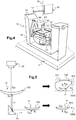
figure 4 est une vue schématique en perspective d'une variante de réalisation du support de la machine d'acquisition d'images de lafigure 1 ; - la
figure 5 est une vue schématique de côté illustrant l'acquisition de deux images d'une lentille au moyen de la machine d'acquisition d'images de lafigure 1 ; - la
figure 6 représente une image vue de face d'une lentille optique ; - la
figure 7 est une vue d'une partie de la lentille optique de lafigure 6 , celle qui sera recouverte par la monture de lunettes ; et - la
figure 8 représente dix photos d'une lentille optique vue sous cinq angles différents, avec et sans monture de lunettes.
- the
figure 1 is a schematic view of an image acquisition machine according to the invention; - the
figure 2 is a schematic sectional view of a set of three locking tips belonging to the image acquisition machine of thefigure 1 ; - the
figure 3 is a schematic perspective view of a locking acorn adapted to be glued to a lens; - the
figure 4 is a schematic perspective view of an alternative embodiment of the support of the image acquisition machine of thefigure 1 ; - the
figure 5 is a schematic side view illustrating the acquisition of two images of a lens by means of the image acquisition machine of thefigure 1 ; - the
figure 6 shows a front view image of an optical lens; - the
figure 7 is a view of part of the optical lens of thefigure 6 , that which will be covered by the spectacle frame; and - the
figure 8 shows ten photos of an optical lens seen from five different angles, with and without spectacle frames.
Il existe trois principales catégories de montures de lunettes. On distingue ainsi les montures de lunettes cerclées, les montures de lunettes semi-cerclées (également appelées montures à arcades) et les montures de lunettes sans cercle (également appelées montures percées).There are three main categories of spectacle frames. A distinction is thus made between rimless spectacle frames, semi-rimless spectacle frames (also called arcaded frames) and spectacle frames. rimless (also called pierced mounts).
Les montures de lunettes cerclées comportent classiquement deux entourages qui sont destinés à accueillir chacun une lentille optique détourée. Ces deux entourages sont reliés l'un à l'autre par un pontet et portent chacun une branche. Chaque entourage présente une rainure, communément appelée drageoir, qui court le long de sa face intérieure.Rimmed spectacle frames conventionally include two surrounds which are each intended to accommodate a cropped optical lens. These two surrounds are connected to each other by a trigger guard and each carry a branch. Each surround has a groove, commonly called a bezel, which runs along its inner face.
Lorsque la monture de lunettes est cerclée, la lentille optique doit être détourée de manière à présenter le long de sa tranche une nervure d'emboîtement, communément appelée biseau, dont la section présente généralement une forme en V. Le biseau ainsi formé sur la tranche de la lentille est alors adapté à venir s'emboîter dans le drageoir de la monture cerclée.When the spectacle frame is rimmed, the optical lens must be cropped so as to present along its edge a fitting rib, commonly called a bevel, the section of which generally has a V-shape. The bevel thus formed on the edge of the lens is then adapted to fit into the bezel of the rimmed frame.
Les montures de lunettes semi-cerclées comportent deux arcades sur les faces intérieures desquelles s'étendent des nervures, ainsi que deux fils de maintien qui sont raccordés aux extrémités des arcades pour former avec celles-ci des contours fermés.Semi-rimmed spectacle frames have two arches on the inner faces of which ribs extend, as well as two retaining wires which are connected to the ends of the arches to form closed contours therewith.
Lorsque la monture de lunettes est semi-cerclée, la lentille optique doit être détourée de manière à présenter en creux le long de sa tranche une rainure périphérique. La lentille est alors maintenue en place dans la monture de lunettes en emboîtant la partie supérieure de sa tranche dans la nervure prévue le long de la face interne de l'arcade correspondante, et en engageant le fil de maintien dans la rainure.When the spectacle frame is semi-rimmed, the optical lens must be cropped so as to have a hollow peripheral groove along its edge. The lens is then held in place in the spectacle frame by fitting the upper part of its edge into the rib provided along the internal face of the corresponding arch, and by engaging the retaining wire in the groove.
Enfin, les montures de lunettes sans-cercle comportent deux branches et un pontet, mais sont dépourvues d'entourage ou d'arcade. Ces branches et ce pontet sont en revanche dotés d'ergots adaptés à s'insérer dans des trous de perçage préalablement réalisés dans les lentilles optiques.Finally, spectacle frames without a circle have two branches and a trigger guard, but have no entourage or arcade. These branches and this bridge are, on the other hand, provided with lugs adapted to be inserted into drill holes previously made in the optical lenses.
Lorsque la monture de lunettes est sans cercle, la lentille optique doit être détourée de manière à présenter une tranche dont la section est droite, puis être percée de manière à ce que l'on puisse y fixer solidement le pontet et la branche correspondante de la monture de lunettes.When the spectacle frame is without a circle, the optical lens must be cropped so as to present a section of which the section is straight, then be drilled so that the trigger guard and the corresponding branch of the eyeglass frame.
Le métier de l'opticien est donc de monter une paire de lentilles neuves (on parle de « lentilles optiques à détourer ») sur la monture de lunettes sélectionnée par le porteur.The job of the optician is therefore to fit a pair of new lenses (we speak of "optical lenses to be cut") on the spectacle frame selected by the wearer.
Il peut s'agir d'une monture de lunettes neuve, ou d'une monture de lunettes usagée (cas où le porteur de lunettes souhaite changer ses lentilles optiques tout en conservant sa monture de lunettes).It can be a new eyeglass frame, or a used eyeglass frame (case where the eyeglass wearer wishes to change his lenses optics while retaining its spectacle frame).
Dans le cas où elle est neuve, la monture de lunettes est généralement fournie à l'opticien avec des lentilles de présentation (ou gabarits) de puissances nulles.If it is new, the spectacle frame is generally supplied to the optician with presentation lenses (or templates) of zero power.
Dans le cas où elle est usagée, la monture de lunettes est généralement fournie à l'opticien avec des lentilles optiques à remplacer.In the event that it is worn, the spectacle frame is usually supplied to the optician with optical lenses to be replaced.
Ces lentilles optiques qui se trouvent initialement dans la monture de lunettes (neuve ou usagée) seront dans la suite de cet exposé désignées par l'expression « lentilles de référence ».These optical lenses which are initially found in the spectacle frame (new or used) will in the remainder of this description be designated by the expression “reference lenses”.
Avant de détourer des lentilles optiques neuves afin de remplacer ces lentilles de référence, l'opticien doit mettre en œuvre une opération d'acquisition du contour selon lequel chaque lentille optique neuve devra être détourée.Before trimming new optical lenses in order to replace these reference lenses, the optician must implement a contour acquisition operation according to which each new optical lens must be cropped.
Ici, cette acquisition sera opérée non pas nécessairement en fonction de la forme de la monture de lunettes, mais plutôt en fonction de la forme des lentilles de référence qui se trouvent initialement dans la monture de lunettes. De cette manière, le procédé utilisé s'appliquera aussi bien aux montures de lunettes cerclées, qu'aux montures de lunettes semi-cerclées et qu'aux montures de lunettes sans cercle.Here, this acquisition will be made not necessarily according to the shape of the spectacle frame, but rather according to the shape of the reference lenses which are initially found in the spectacle frame. In this way, the method used will apply equally to rimless spectacle frames, to semi-rimless spectacle frames and to rimless spectacle frames.
Comme le montre la
Cette machine d'acquisition d'images 1 comporte à cet effet :
un châssis 2,un support 10 pour une lentille de référence,- d'un côté du
support 10, une source de lumière 20, - d'un côté ou de l'autre côté du
support 10, un capteur d'images 30 adapté à capturer au moins deux images de la lentille de référence vue sous deux angles différents.
- a
frame 2, - a
support 10 for a reference lens, - on one side of the
support 10, alight source 20, - on one side or the other side of the
support 10, animage sensor 30 adapted to capture at least two images of the reference lens seen from two different angles.
Pour acquérir deux images de la lentille de référence sous deux angles différents, on pourra prévoir de monter le capteur d'images 30 de telle manière qu'il soit mobile par rapport au châssis 2 et/ou de monter la lentille de référence sur le support 10 de telle manière qu'elle soit mobile par rapport au châssis 2.To acquire two images of the reference lens from two different angles, provision may be made to mount the
Dans le mode de réalisation de la machine d'acquisition d'images 1 représentée sur la
Cette tige 11 est ici droite. Elle s'étend selon un axe principal A3, qui est en pratique vertical. Ici, cette tige 11 est fixée au support 2 par son extrémité basse.This
La source de lumière 20 comporte ici un système d'éclairage direct 21, qui permet d'éclairer la lentille de référence par le dessous, c'est-à-dire à l'opposé du capteur d'images 30 par rapport à la lentille.The
Ce système d'éclairage direct 21 comporte un plateau translucide en forme de disque, qui est traversé en son centre par la tige 11 de telle manière qu'il s'étend tout autour de la tige 11.This
Différentes sources lumineuses, telles que des diodes électroluminescentes, permettent d'éclairer par le dessous ce plateau translucide, de telle manière qu'il forme une source de lumière étendue.Various light sources, such as light-emitting diodes, make it possible to illuminate this translucent plate from below, in such a way that it forms an extended light source.
En variante, on pourra prévoir de compléter ou de remplacer ce système d'éclairage direct 21 par un système d'éclairage latéral (non représenté) éclairant la lentille de référence par sa tranche. Ce système d'éclairage latéral pourra être placé sur le côté de la tige 11, à hauteur du dessus ou du dessous de l'extrémité libre de cette tige 11, de manière à éclairer la lentille de référence portée par cette tige 11.As a variant, provision may be made to supplement or replace this
Le capteur d'images 30 est quant à lui formé par une caméra numérique.The
Cette caméra numérique ne comporte pas un objectif télécentrique. L'utilisation d'un objectif télécentrique permettrait de conserver un même rapport de grossissement de la lentille quelle que soit la distance de prise de vue. Malheureusement, un tel objectif est très complexe à fabriquer.This digital camera does not have a telecentric lens. The use of a telecentric lens would make it possible to maintain the same magnification ratio of the lens regardless of the shooting distance. Unfortunately, such a lens is very complex to manufacture.
C'est la raison pour laquelle selon l'invention, l'objectif choisi est ici non télécentrique (il s'agit donc d'un objectif entocentrique).This is the reason why, according to the invention, the objective chosen here is not telecentric (it is therefore an entocentric objective).
Ici, on se propose alors, comme cela sera bien décrit dans la suite de cet exposé, de traiter les images acquises de manière à tenir compte des changements d'échelles dues aux variations de distances de prise de vue, de manière à obtenir de résultats aussi précis que ceux qu'on obtiendrait en utilisant un objectif télécentrique.Here, we then propose, as will be well described in the remainder of this presentation, to process the acquired images so as to take into account the changes in scales due to the variations in shooting distances, so as to obtain results. as precise as those that would be obtained using a telecentric lens.
Le capteur d'images 30 est ici monté sur le châssis 2 de telle manière que son axe optique A4 reste parallèle à l'axe principal A3 de la tige 11 du support 10.The
Il est plus précisément ici monté mobile sur le châssis 2 de telle sorte qu'il peut acquérir non seulement une image de face de la lentille de référence, mais également une image de côté de cette lentille, sans qu'il soit nécessaire pour cela de bouger la lentille de référence.It is more precisely here mounted movably on the
Pour cela, le capteur d'images 30 est monté sur le châssis 2 avec une mobilité de translation suivant un axe A5 perpendiculaire à son axe optique A4. Il est ainsi mobile entre une position de base dans laquelle son axe optique A4 est confondu avec l'axe principal A3 de la tige 11, et une position escamotée dans laquelle son axe optique A4 est strictement parallèle à l'axe principal A3.For this, the
Il est en outre ici prévu un miroir 70 qui permet, lorsque le capteur d'images 30 est en position escamotée, de réfléchir une image du côté de la lentille de référence vers ce capteur d'images 30.A
Ce miroir 70 s'étend à cet effet dans un plan dont la normale au centre du miroir coupe l'axe principal A3 avec un angle d'inclinaison de 45 degrés.This
Ce miroir 70 est ainsi positionné de telle manière que, lorsque le capteur d'images 30 est en position escamotée, le miroir 70 se trouve dans le champ du capteur d'images.This
Comme le montre la
En variante, on pourrait prévoir que le capteur d'images reste immobile, et que le miroir soit mobile pour se placer dans le champ du capteur d'images afin de renvoyer vers celui-ci une image de côté de la lentille (via par exemple d'autres miroirs).As a variant, provision could be made for the image sensor to remain stationary, and for the mirror to be mobile so as to be placed in the field of the image sensor in order to send back an image from the side of the lens to the latter (via for example other mirrors).
Dans la présente invention, lorsque la lentille de référence est percée, on souhaite acquérir au moins une autre image de la lentille de référence, vue sous un autre angle.In the present invention, when the reference lens is pierced, it is desired to acquire at least one other image of the reference lens, seen from another angle.
En effet, les seules vues de face et de côté de la lentille ne permettent pas de caractériser précisément les formes et positions des trous de perçage prévus dans la lentille de référence.Indeed, the only front and side views of the lens do not make it possible to precisely characterize the shapes and positions of the drill holes provided in the reference lens.
Pour cela, la présente invention propose d'acquérir d'autres images, sur lesquelles les trous de perçages sont sensiblement situés dans l'axe du capteur d'images 30.For this, the present invention proposes to acquire other images, on in which the drill holes are substantially located in the axis of the
Sur la
Sur cette
Comme le montre la
Il est ici prévu trois embouts de blocage 40, 50, 60.Three blocking
Chaque embout de blocage 40, 50, 60 comporte :
- une partie de préhension 41, 51, 61 pour sa fixation sur la tige 11 selon un premier axe A1, et
- une partie d'accueil 42, 52, 62 pour sa fixation au gland de blocage 90 selon un second axe A2, l'angle d'inclinaison entre le premier axe A1 et le second axe A2 variant d'un embout de blocage 40, 50, 60 à l'autre.
- a gripping
portion rod 11 along a first axis A1, and - a receiving
part glans 90 along a second axis A2, the angle of inclination between the first axis A1 and the second axis A2 varying from a lockingend piece
Ici, les parties de préhension 41, 51, 61 des trois embouts de blocage 40, 50, 60 sont identiques. Elles sont prévues pour se fixer à la tige 11 par emboîtement. Elles se présentent alors sous la forme de manchons symétriques de révolution autour du premier axe A1. Ces manchons présentent des diamètres intérieurs identiques (au jeu de montage près) au diamètre extérieur de la tige 11, ce qui leur assure une bonne stabilité sur l'extrémité libre de la tige 11.Here, the gripping
Les parties d'accueil 42, 52, 62 des trois embouts de blocage 40, 50, 60 sont quant à elles prévues pour se fixer au pion 92 du gland de blocage 90. Elle comportent à cet effet chacune une cavité permettant de loger le pion 92.The receiving
Comme cela apparaît en pointillés sur la
Ici, les faces supérieures de ces parties d'accueil 42, 52, 62 présentent des formes identiques, mais elles sont orientées différemment par rapport aux parties de préhension 41, 51, 61.Here, the upper faces of these receiving
L'axe de symétrie de la partie d'accueil 42, 52, 62 de chaque embout (appelé ici second axe A2) présente une inclinaison par rapport au premier axe A1 qui diffère d'un embout à l'autre.The axis of symmetry of the receiving
Dans l'exemple représenté sur la
De cette manière, en fixant successivement la lentille de référence à la tige 11 au moyen de ces embouts de blocage 40, 50, 60, il est possible d'acquérir des images de la lentille de référence avec différents angles d'inclinaison.In this way, by successively fixing the reference lens to the
En changeant d'embout de blocage, le risque est alors de perdre le référentiel de la lentille de référence entre les différentes acquisitions d'images.By changing the blocking tip, the risk is then to lose the frame of reference of the reference lens between the different acquisitions of images.
Pour éviter cela, comme le montre la
De cette manière, en plaçant à chaque fois le centre boxing de la lentille de référence au niveau de ce point d'intersection, on s'assure de bien conserver le référentiel de la lentille de référence (ce référentiel étant ensuite conservé pour l'usinage de la lentille).In this way, by placing the boxing center of the reference lens at the level of this point of intersection each time, it is ensured that the reference lens of the reference lens is properly preserved (this reference being then kept for machining. lens).
En l'espèce, ce point d'intersection sera situé à une distance donnée de la face supérieure de la partie d'accueil 42, 52, 62, cette distance correspondant à l'épaisseur du plateau 91 du gland de blocage 90 et de l'autocollant double-face utilisé.In this case, this point of intersection will be located at a given distance from the upper face of the
Comme le montre la
Ici, les embouts de blocage 40, 50, 60 seront fabriqués soit à la demande, au moyen d'une imprimante 3D ou de toute autre technique adaptée (prototypage rapide, ...), soit en série par moulage d'une matière plastique.Here, the blocking
Selon une variante de l'invention représentée sur la
Le support 10 sera préférentiellement monté mobile par rapport au châssis 2 avec au moins deux mobilités de rotation autour de deux axes distincts, et deux mobilités de translation selon deux axes distincts.The
Dans cette variante, la tige 11 n'est pas fixée au châssis 2 de la machine d'acquisition d'images 1, mais elle est montée sur le châssis 2 avec deux mobilités de rotation autour de deux axes A6, A7 non parallèles.In this variant, the
Cette tige 11 est ainsi montée mobile en rotation autour d'un premier axe A6 qui est perpendiculaire à l'axe principal A3 de la tige 11. Ce premier axe A6 est en pratique horizontal.This
La tige 11 est en outre montée mobile en rotation autour d'un second axe A7 qui est perpendiculaire au premier axe A6. Ce second axe A7 est en pratique confondu avec l'axe principal A3.The
Pour lui conférer ces deux mobilités, la tige 11 s'élève à partir d'un plateau 12, qui est monté mobile en rotation (autour de l'axe principal A3) sur un socle 13, ce socle 13 étant lui-même monté mobile en rotation (autour du premier axe A6) sur une embase 14 posée sur le châssis 2.To give it these two mobilities, the
Ici, l'embase 14 présente une forme en U, avec une partie inférieure plane qui repose sur le châssis 2, et deux montants latéraux qui s'élèvent au-dessus du châssis 2.Here, the
Le socle 13 est alors relié à cette embase 14 par deux arches latérales en formes de V renversés, dont les extrémités sont fixées au socle 13 et dont les sommets portent des ergots montés pivotants dans deux paliers lisses de l'embase 14.The
Le montage des ergots dans les paliers lisses de l'embase 14 est serré de telle sorte que, d'une part, l'opticien peut faire manuellement basculer le socle 13 autour du premier axe A6, et que, d'autre part, une fois basculé, le socle 13 reste en position inclinée et ne revient pas naturellement en position initiale.The mounting of the lugs in the plain bearings of the
Le plateau 12 comporte pour sa part une assise circulaire qui repose sur la face supérieure du socle 13. Il est prévu, en creux dans la face supérieure du socle 13 et dans l'assise circulaire du plateau 12, des gorges annulaires en regard qui permettent d'accueillir un anneau de guidage de la rotation du plateau 12 autour de l'axe principal A3.The
De cette manière, en réglant la position angulaire du plateau 12 autour de l'axe principal A3 et celle du socle 13 autour du premier axe A6, il est possible de faire basculer la lentille de référence fixée à l'accessoire de blocage 40 dans une position inclinée par rapport à l'axe optique A4 du capteur d'images 30, afin d'acquérir des images inclinées de la lentille de référence.In this way, by adjusting the angular position of the
Il est également possible de déplacer l'embase 14 en la faisant glisser sur le châssis 2, de manière à pouvoir placer l'axe de la tige 11 dans l'axe optique A4 du capteur d'images 30, ou à distance de celui-ci.It is also possible to move the
En variante, on pourrait prévoir d'utiliser des moteurs électriques pour actionner automatiquement les mobilités du support 10 par rapport au châssis 2. Ici encore, pour éviter tout problème de changement de référentiel lors du pivotement du socle 13 autour du premier axe A6, le support 10 est conçu de telle manière que le point d'intersection du premier axe A6 et de l'axe principal A3 est situé à une distance donnée de la face supérieure de la partie d'accueil 42 de l'accessoire de blocage 40, cette distance correspondant à l'épaisseur du plateau 91 du gland de blocage 90 et de l'autocollant double-face utilisé.As a variant, provision could be made to use electric motors to automatically actuate the mobility of the
On notera par ailleurs sur la
Sur les photos 3, 5, 7 et 9 de la
Sur les autres photos, on a représenté des images correspondantes de cette lentille de référence 100 (vue de face, de côté, et inclinée), lorsqu'elle est montée dans sa monture de lunettes 150.In the other photos, corresponding images have been shown of this reference lens 100 (front view, side view, and tilted), when it is mounted in its
Pour piloter les différents organes de la machine d'acquisition d'images 1, il est prévu un calculateur (non représenté) comportant un processeur, une mémoire vive (RAM), une mémoire morte (ROM), des convertisseurs analogiques-numériques, et différentes interfaces d'entrée et de sortie.To control the various components of the
Grâce à ses interfaces d'entrée, le calculateur est adapté à recevoir de différentes interfaces homme/machine (écran tactile, bouton, ...) des signaux d'entrée relatifs à la volonté de l'opticien. L'opticien peut ainsi commander l'allumage de la source d'éclairage 20, l'acquisition d'une image par le capteur d'images 30, le traitement des images acquises, la mise en marche des moteurs électriques, ...Thanks to its input interfaces, the computer is suitable for receiving from various man / machine interfaces (touch screen, button, etc.) input signals relating to the wishes of the optician. The optician can thus control the switching on of the
Dans sa mémoire vive, le calculateur mémorise les différentes images acquises de la lentille de référence.In its random access memory, the computer stores the various images acquired from the reference lens.
Dans sa mémoire morte, le calculateur mémorise un logiciel de traitement des images acquises, qui permet de générer des paramètres de détourage d'une lentille neuve.In its read-only memory, the computer stores software for processing the acquired images, which makes it possible to generate parameters for trimming a new lens.
Enfin, grâce à ses interfaces de sortie, le calculateur est adapté à transmettre ces paramètres de détourage à au moins une machine de détourage de lentilles optiques.Finally, thanks to its output interfaces, the computer is suitable for transmitting these trimming parameters to at least one optical lens trimming machine.
Pour élaborer une consigne de détourage d'une lentille neuve, on procède alors en plusieurs étapes. Les étapes principales de ce procédé sont les suivantes :
- a) une étape de démontage de la lentille de référence 100 et de fixation de cette lentille de référence 100 sur le
support 10 de la machine d'acquisitiond'images 1, - b) une étape d'acquisition, par le capteur d'images 30, d'au moins deux images de la lentille de référence 100 vue sous deux angles différents,
- c) une étape de traitement des images acquises pour en déduire des paramètres de détourage de ladite lentille neuve, et
- d) une étape d'élaboration de la consigne de détourage en fonction desdits paramètres de détourage.
- a) a step of removing the
reference lens 100 and fixing thisreference lens 100 on thesupport 10 of theimage acquisition machine 1, - b) a step of acquisition, by the
image sensor 30, of at least two images of thereference lens 100 seen from two different angles, - c) a step of processing the acquired images in order to deduce therefrom the parameters for trimming said new lens, and
- d) a step of developing the trimming instruction as a function of said trimming parameters.
A ce stade, on précisera que la consigne de détourage est généralement élaborée par la machine de détourage elle-même, à partir de différents paramètres de détourage. En effet, la consigne de détourage va être élaborée en fonction de la cinématique de la machine de détourage concernée, si bien qu'elle ne peut généralement pas être élaborée en amont.At this stage, it will be specified that the trimming instruction is generally produced by the trimming machine itself, from various trimming parameters. Indeed, the trimming instruction will be developed according to the kinematics of the trimming machine concerned, so that it generally cannot be produced upstream.
On peut exposer en détail la mise en œuvre des étapes a) à c) du procédé précité. L'étape d), bien connue de l'homme du métier, ne sera en revanche pas ici décrite en détail.The implementation of steps a) to c) of the aforementioned method can be described in detail. Step d), well known to those skilled in the art, will not however be described in detail here.
A l'étape a), l'opticien démonte l'une des deux lentilles de référence 100 de la monture de lunettes 150, de manière à pouvoir acquérir des images de la lentille de référence 100 nue, sur lesquelles apparait l'ensemble du contour de cette lentille de référence 100.In step a), the optician dismantles one of the two
Ici, on considérera que l'opticien dispose d'une machine d'acquisition d'images 1 comportant un support 10 du type de celui représenté sur la
Après avoir extrait la lentille de référence 100 de sa monture, l'opticien fixe le gland de blocage 90 sur la lentille de référence 100 au moyen d'un autocollant double-face, en prenant soin que l'axe du pion 92 passe par le centre boxing de la lentille de référence 100. Des marquages prévus sur la lentille et sur le gland de blocage 90 pour identifier le centre boxing et l'axe du pion 92 permettent de faciliter cette opération.After having extracted the
L'opticien peut en variante s'aider d'un dispositif centreur-bloqueur dont l'utilisation est bien connue par ailleurs et permet d'obtenir des résultats plus précis.As a variant, the optician can use a centering-blocking device, the use of which is well known elsewhere and makes it possible to obtain more precise results.
Selon une autre variante, l'opticien pourrait utiliser un gland de blocage pneumatique, se présentant sous la forme d'une ventouse à rapporter sur la lentille et à fixer à cette dernière au moyen d'une pompe à vide.According to another variant, the optician could use a pneumatic locking acorn, in the form of a suction cup to be attached to the lens and to be fixed to the latter by means of a vacuum pump.
Ici, l'opticien rapporte ensuite le gland de blocage 90 muni de la lentille de référence 100 sur l'accessoire de blocage 40 fixé à l'extrémité de la tige 11.Here, the optician then attaches the blocking
Il place ensuite le berceau 12 du support 10 dans une position initiale droite (dans laquelle l'axe principal A3 de la tige 11 se confond avec le second axe A7).It then places the
Alors, la machine d'acquisition d'images 1 est prête à acquérir des images de la lentille de référence 100.Then, the
A l'étape b), l'opticien commande l'acquisition d'images de la lentille de référence 100, via un moyen de saisie quelconque équipant la machine d'acquisition d'images 1 (clavier, écran tactile, ...).In step b), the optician controls the acquisition of images from the
Lors de cette étape, le capteur d'images 30 est commandé pour acquérir une image de face 100A de la lentille de référence 100 (voir
Le calculateur commande ensuite le déplacement du capteur d'images 30 depuis sa position de base vers sa position escamotée, via par exemple un système de pignon-crémaillère commandé par un moteur électrique. Le calculateur commande ensuite l'acquisition d'une image de côté 100B de la lentille de référence 100.The computer then controls the displacement of the
Le calculateur commande ensuite le retour du capteur d'images 30 en position de base.The computer then controls the return of the
Lorsque la lentille de référence 100 présente des trous de perçage, l'opticien incline alors manuellement le berceau 12 du support 10 de telle manière que l'un des trous de perçage se trouve positionné sensiblement verticalement. Il commande ensuite l'acquisition d'une nouvelle image inclinée de la lentille. Il procède de la même manière pour tous les autres trous de perçage.When the
En variante, lorsque l'inclinaison du berceau est commandée par un moteur électrique, la consigne d'inclinaison envoyée au moteur électrique peut être calculée automatiquement par le calculateur.As a variant, when the inclination of the cradle is controlled by an electric motor, the inclination setpoint sent to the electric motor can be calculated automatically by the computer.
Elle peut en particulier être calculée en fonction de la forme du trou de perçage sur l'image de face (sur cette image de face, le trou présente une forme oblongue et non circulaire). En effet, il est possible de déterminer sur cette image de face l'orientation du trou de perçage, et d'en déduire une consigne d'inclinaison à envoyer aux moteurs électriques.It can in particular be calculated as a function of the shape of the drill hole on the front image (on this front image, the hole has an oblong shape and not a circular one). Indeed, it is possible to determine on this face image the orientation of the drill hole, and to deduce therefrom an inclination setpoint to be sent to the electric motors.
Ainsi, à ce stade, si la lentille de référence 100 ne présente pas de trou de perçage, la mémoire vive du calculateur mémorise au moins deux images de la lentille de référence 100 vue de face (c'est-à-dire vue de la face avant) et vue de dos (c'est-à-dire vue de la face arrière). En revanche, si la lentille de référence 100 présente par exemple quatre trous de perçage, la mémoire vive du calculateur mémorise six images de la lentille de référence 100.Thus, at this stage, if the
Une fois ces images acquises, l'opticien remonte la monture de lunettes 150 sur la lentille de référence 100, alors que cette dernière est encore montée sur la tige 11.Once these images have been acquired, the optician reassembles the
Comme cela apparaît sur la
En pratique, l'opticien commande l'acquisition de deux autres images : une image de face et une image de côté de la lentille de référence 100 montée dans sa monture de lunettes 150.In practice, the optician orders the acquisition of two other images: a front image and a side image of the
Enfin, l'opticien commande le démarrage du traitement des images acquises par le calculateur.Finally, the optician orders the start of processing of the images acquired by the computer.
Puisque les images ont été acquises à l'aide d'un objectif non télécentrique, la première opération de traitement consiste à redimensionner les images mémorisées.Since the images were acquired using a non-telecentric lens, the first processing step is to resize the stored images.
En effet, dans ce cas, la distance entre l'objectif et la lentille de référence 100 varie d'un point à l'autre de la lentille, ce qui génère une distorsion de l'image acquise qu'il convient de corriger afin d'obtenir des résultats de mesure fiables.Indeed, in this case, the distance between the objective and the
Dans le cas où l'objectif utilisé serait télécentrique (ce qui n'est pas le cas dans l'invention), cette première opération serait inutile.If the objective used is telecentric (which is not the case in the invention), this first operation would be unnecessary.
Ici, cette première opération consiste alors à corriger les coordonnées de chaque point caractéristique de l'image acquise.Here, this first operation then consists in correcting the coordinates of each characteristic point of the acquired image.
Le préalable de cette opération est de déterminer la courbure de la lentille de référence 100, cette courbure permettant ensuite de déterminer la distance séparant le capteur d'images 30 de la lentille de référence 100, ce qui permettra de remettre chaque image à l'échelle.The prerequisite for this operation is to determine the curvature of the
Pour déterminer cette courbure, on pourra acquérir le rayon de courbure de la face avant convexe de la lentille de référence 100 soit en la lisant dans une base de données, soit en la mesurant à l'aide d'un appareil adapté, soit en la calculant sur l'image de la lentille de profil.To determine this curvature, the radius of curvature of the convex front face of the
En effet, comme le montre la
Ensuite, pour bien comprendre comment le calculateur opère l'opération de mise à l'échelle des images acquises, on peut s'intéresser à un point P repérable sur l'image de face 100A et sur l'image de côté 100B de la lentille de référence 100 (voir
On cherche alors à déterminer les coordonnées tridimensionnelles Xmm, Ymm, Zmm de ce point P, exprimées en millimètres, alors qu'on ne dispose que des coordonnées bidimensionnelles (XZ1, YZ1) et (XZ2, ZZ2) de ce point P, relevées en pixels sur les deux images 100A, 100B.We then seek to determine the three-dimensional coordinates X mm , Y mm , Z mm of this point P, expressed in millimeters, while we only have the two-dimensional coordinates (X Z1 , Y Z1 ) and (X Z2 , Z Z2 ) of this point P, read in pixels on the two
On peut écrire le système de six équations suivantes :
- Xmm = XZ1 * SZ1, avec SZ1 la hauteur du point P par rapport au centre boxing (qui est déduit de la courbure de la lentille),

- SZ1 = a * Zmm + S0, a et S0 étant deux constantes connues (déterminées lors de la calibration de la machine d'acquisition d'images 1),
- Xmm = XZ2 * SZ2, avec SZ2 l'écart horizontal entre le point P et le centre boxing (qui est déduit de la courbure de la lentille),

- SZ2 = a * (Ymm - (L1+L2)) + S0, L1 et L2 étant deux constantes connues (déterminées lors de la calibration de la machine d'acquisition d'images 1).
- X mm = X Z1 * S Z1 , with S Z1 the height of point P with respect to the boxing center (which is deduced from the curvature of the lens),
- S Z1 = a * Z mm + S 0 , a and S 0 being two known constants (determined during the calibration of the image acquisition machine 1),
- X mm = X Z2 * S Z2 , with S Z2 the horizontal distance between point P and the boxing center (which is deduced from the curvature of the lens),
- S Z2 = a * (Y mm - (L1 + L2)) + S 0 , L1 and L2 being two known constants (determined during the calibration of the image acquisition machine 1).
En pratique, seul le résultat de la résolution de ce système d'équation est mémorisé dans la mémoire morte du calculateur. Ce résultat est le suivant : ![]()
![]()
![]()
![]()
![]()
![]()
En appliquant ce résultat à tous les points caractéristiques de l'image, le calculateur peut alors redimensionner les images acquises de façon à obtenir des résultats non déformés malgré l'utilisation d'un objectif non télécentrique.By applying this result to all the characteristic points of the image, the computer can then resize the acquired images so as to obtain undistorted results despite the use of a non-telecentric lens.
Une fois les images acquises redimensionnées, la seconde opération consiste à traiter les images de la lentille de référence 100 nue.Once the acquired images have been resized, the second operation consists in processing the images of the
La première des images traitées est l'image vue de face 100A.The first of the processed images is the
On a par exemple représenté sur la
Afin d'obtenir des paramètres de détourage à transmettre à une machine de détourage, le calculateur va examiner le contour 101 de l'image vue de face 100A de la lentille de référence 100, il va déterminer la ou les zones de la lentille qui vont être recouvertes par la monture de lunettes, et il va caractériser le ou les trous de perçage prévus dans la lentille de référence 100.In order to obtain trimming parameters to be transmitted to a trimming machine, the computer will examine the
Sur l'image vue de face 100A, le contour 101 de la lentille de référence 100 présente des zones convexes et deux zones concaves localisées. Ce contour 101 est alors caractérisé par une pluralité de points qui s'étendent le long de son pourtour, et qui sont régulièrement répartis sur celui-ci. Les coordonnées bidimensionnelles de ces points formeront des premiers paramètres de détourage à transmettre à la machine de détourage.In the front-
Le calculateur va ensuite traiter en combinaison les images vues de face de la lentille de référence 100 nue et de la lentille de référence 100 montée dans sa monture de lunettes 150.The computer will then process in combination the images seen from the front of the
Il va ainsi pouvoir déterminer la zone située à l'intérieur du contour 101 qui correspond à la zone de la lentille de référence 100 qui est recouverte par la monture de lunettes 150. Cette zone 105 est représentée sur la
Pour cela, en repérant la position du contour de la monture de lunettes 150, le calculateur va reporter ce contour sur l'image vue de face 100A de la lentille de référence 100 nue, et ainsi caractériser cette zone 105.To do this, by locating the position of the outline of the
Il va ainsi pouvoir déterminer la ou les zones de conflits situées à l'intérieur du contour 101 qui correspondent aux endroits où la lentille neuve risquera d'interférer avec la monture de lunettes 150 et créer des collisions par exemple avec les plaquettes nasales ou les bords avant et/ou arrières de la monture. En effet, contrairement à la lentille de référence 100 qui présente généralement une épaisseur réduite, la lentille neuve pourra présenter une importante épaisseur au bord, ce qui pourrait générer un conflit entre la lentille neuve et la monture de lunettes 150.He will thus be able to determine the conflict zone or zones located inside the
En déterminant la forme tridimensionnelle d'une partie de la monture de lunettes 150 à l'aide des images vues de face et de côté acquises, le calculateur pourra alors déterminer si un tel conflit risque d'arriver, et si tel est le cas, il pourra déterminer des seconds paramètres de détourage, visant à créer un biseau incliné dans les zones de conflit avec les plaquettes nasale et/ou à permettre d'usiner un épaulement (ou un renfoncement) dans la tranche de la lentille neuve comme précisé dans le brevet
Le calculateur va ensuite traiter l'image vue de face 100A de la lentille ophtalmique 100 nue afin de déterminer si cette lentille présente un ou plusieurs trous de perçage.The computer will then process the image seen from the front 100A of the bare
Si tel est le cas, le calculateur va sélectionner, parmi les différentes images acquises de la lentille de référence nue, celle sur laquelle les contours des débouchés avant et arrière du trou de perçage considéré sont les plus proches. Cette image correspondra à celle pour laquelle le trou de perçage était orienté sensiblement dans l'axe du capteur d'images 30.If this is the case, the computer will select, from among the various images acquired of the bare reference lens, the one on which the contours of the front and rear outlets of the bore hole in question are the closest. This image will correspond to that for which the drill hole was oriented substantially in the axis of the
Alors, sur cette image, le calculateur 100 va calculer la forme et la position de ce trou de perçage. La forme et la position de chaque trou de perçage formeront des troisièmes paramètres de détourage.Then, on this image, the
Après avoir caractérisé l'ensemble des trous de perçage situés dans la lentille de référence 100, le calculateur traite l'image vue de côté 100B de la lentille de référence 100.After having characterized all the drilling holes located in the
La présente invention n'est nullement limitée au mode de réalisation décrit et représenté, mais l'homme du métier saura y apporter toute variante conforme aux limitations telles que définies par les revendications.The present invention is in no way limited to the embodiment described and shown, but those skilled in the art will know how to make any variant in accordance with the limitations as defined by the claims.
On pourrait par exemple prévoir que le support de lentille soit immobile et que le capteur d'images soit monté mobile en rotation sur le châssis de la machine d'acquisition d'images, autour d'un axe passant par le centre boxing de la lentille de référence. De cette manière, ce capteur d'images pourra acquérir une image de face de la lentille de référence, puis il pourra pivoter afin d'acquérir des images inclinées et de côté de la lentille de référence, sans qu'il soit nécessaire de déplacer la lentille de référence.For example, provision could be made for the lens support to be stationary and for the image sensor to be mounted so as to be able to rotate on the frame of the image acquisition machine, around an axis passing through the boxing center of the lens. reference. In this way, this image sensor will be able to acquire a front image of the reference lens, then it will be able to rotate in order to acquire tilted and side images of the reference lens, without it being necessary to move the lens. reference lens.
Claims (13)
- Method of determining a guideline for trimming an optical lens to be trimmed with a view to its mounting in a spectacle frame (150) in which is mounted at least one reference optical lens (100), comprising steps:a) of removing the said reference optical lens (100) and of fixing the said reference optical lens (100) on a support (10) of a machine for acquiring images (1),b) of acquiring, with an image sensor (30) of the said machine for acquiring images (1) that comprises an entocentric objective, at least two images of the said reference optical lens (100) viewed from two different angles,c) of processing the said at least two images so as to deduce therefrom trimming parameters for the said optical lens to be trimmed, andd) of devising the said trimming guideline as a function of the said trimming parameters,wherein, in step c), the curvature of one of the faces of the said reference optical lens (100) is acquired, and each image acquired is scaled as a function of the said curvature.
- Method of determining according to claim 1, in which, in step b), the said at least two images are acquired successively, a mirror (70) being placed in the optical path of the image sensor (30) between the two image acquisitions.
- Method of determining according to one of Claims 1 and 2, in which, in step b), the said at least two images are acquired successively, while inclining, between the two image acquisitions, the said reference optical lens (100) with respect to the image sensor (30) by a known angle about an axis of rotation which passes through the boxing centre of the reference optical lens (100).
- Method of determining according to one of Claims 1 to 3, in which, in step b), at least one image of the reference optical lens (100) mounted in the spectacle frame (150) is also acquired, and in step c), the said image is processed so as to deduce therefrom at least one of the said trimming parameters.
- Method of determining according to one of Claims 1 to 4, in which, in step b), one of the two images of the reference optical lens (100) is acquired sideon, in such a way that the reference optical lens (100) extends in a mid-plane substantially parallel to an axis of the optical path of the said image sensor (30) and, in step c), the radius of curvature of one of the optical faces of the reference optical lens (100) is determined.
- Method of determining according to one of Claims 1 to 5, in which, in step b), one of the two images of the reference optical lens (100) is acquired face-on, in such a way that the reference optical lens extends in a mid-plane substantially orthogonal to an axis of the optical path of the said image sensor (30) and, in step c), the two-dimensional shape of the outline (101) of the reference optical lens (100) is read off on the image acquired face-on.
- Method of determining according to one of Claims 1 to 6, in which, in step c):- a search is conducted for each drill hole of the reference optical lens (100),- for each drill hole found, the image is selected on which the outlines of the front and rear openings of the said drill hole are the closest, and- at least one trimming parameter is assigned to the characterization of the shape and of the position of the said drill hole on the selected image.
- Machine for acquiring images (1) of optical lenses, comprising:- a support (10) for a reference optical lens (100),- a light source (20),- an image sensor (30) comprising an entocentric objective and that is suitable for capturing a first image of the reference optical lens (100) carried by the support (10), viewed from a first angle, and a second image of the reference optical lens (100) carried by the support (10), viewed from a second angle distinct from the first anglecharacterized in that it comprises a processing unit that memorizes a processing software suitable to operate steps c) and d) of a method according to one of the preceding claims.
- Machine for acquiring images (1) according to Claim 8, in which the said image sensor (30) and the said light source (20) are disposed on either side of the reference optical lens (100) carried by the support (10).
- Machine for acquiring images (1) according to Claim 8, in which the said image sensor (30) and the said light source (20) are disposed on one and the same side of the reference optical lens (100) carried by the support (10).
- Machine for acquiring images (1) according to one of Claims 8 to 10, in which the said support (10) comprises a stand (11) and a set of at least two locking caps (40, 50, 60), each locking cap (40, 50, 60) comprising:- a gripping part (41, 51, 61) for its fixing onto the said stand (11) according to a first axis (A1), and- an accommodating part (42, 52, 62) for its fixing to the said reference optical lens (100) according to a second axis (A2), the angle of inclination between the first axis (A1) and the second axis (A2) varying from one locking cap (40, 50, 60) to the other.
- Machine for acquiring images (1) according to one of Claims 8 to 10, in which there is provided a chassis (2) and in which the support (10) comprises a locking cap (40) for the fixing of the said reference optical lens (100), which is mounted mobile with respect to the chassis (2) with at least two mobilities of rotation about two non-parallel axes (A6, A7).
- Machine for acquiring images (1) according to one of Claims 8 to 12, in which there is provided a mirror (70) and in which the image sensor (30) and the support (10) are mounted mobile with respect to one another, between a first position in which the support (10) is situated in the field of the image sensor (30) and a second position in which the mirror (70) is situated in the field of the image sensor (30).
Applications Claiming Priority (2)
| Application Number | Priority Date | Filing Date | Title |
|---|---|---|---|
| FR1457240A FR3024247B1 (en) | 2014-07-25 | 2014-07-25 | OPTICAL LENS IMAGE ACQUISITION MACHINE AND METHOD FOR OPTICAL LENS DETOURING |
| PCT/FR2015/052032 WO2016012720A1 (en) | 2014-07-25 | 2015-07-23 | Machine for acquiring images of optical lenses and process for trimming optical lenses |
Publications (2)
| Publication Number | Publication Date |
|---|---|
| EP3172011A1 EP3172011A1 (en) | 2017-05-31 |
| EP3172011B1 true EP3172011B1 (en) | 2021-09-01 |
Family
ID=52016707
Family Applications (1)
| Application Number | Title | Priority Date | Filing Date |
|---|---|---|---|
| EP15756199.4A Active EP3172011B1 (en) | 2014-07-25 | 2015-07-23 | Machine for acquiring images of optical lenses and process for trimming optical lenses |
Country Status (5)
| Country | Link |
|---|---|
| US (2) | US10406649B2 (en) |
| EP (1) | EP3172011B1 (en) |
| CN (2) | CN205090947U (en) |
| FR (1) | FR3024247B1 (en) |
| WO (1) | WO2016012720A1 (en) |
Families Citing this family (2)
| Publication number | Priority date | Publication date | Assignee | Title |
|---|---|---|---|---|
| FR3024246B1 (en) * | 2014-07-25 | 2016-08-05 | Essilor Int | METHOD FOR PRODUCING A DETOURING SETTING OF AN OPTICAL LENS |
| FR3024247B1 (en) * | 2014-07-25 | 2018-02-09 | Essilor International | OPTICAL LENS IMAGE ACQUISITION MACHINE AND METHOD FOR OPTICAL LENS DETOURING |
Family Cites Families (17)
| Publication number | Priority date | Publication date | Assignee | Title |
|---|---|---|---|---|
| US5686960A (en) * | 1992-01-14 | 1997-11-11 | Michael Sussman | Image input device having optical deflection elements for capturing multiple sub-images |
| US5428448A (en) * | 1993-10-20 | 1995-06-27 | Augen Wecken Plasticos S.R.L. De C.V. | Method and apparatus for non-contact digitazation of frames and lenses |
| US5604583A (en) * | 1995-03-20 | 1997-02-18 | Bausch & Lomb Incorporated | Computer vision inspection station |
| FR2751433B1 (en) | 1996-07-18 | 1998-10-09 | Essilor Int | PROCESS FOR TAKING UP THE CROWNING SECTION OF A GLASSES FRAME, CORRESPONDING SENSOR, AND APPLICATION OF THIS PROCESS TO OVERFLOWING THE MOUNTING GLASS |
| US6243960B1 (en) | 1999-03-16 | 2001-06-12 | National Optronics, Incorporated | Tracer, clamp and object engager for holding and tracing a lens mount of an eyeglass frame, a lens, and/or a lens pattern, to reliably detect a shape thereof even when the shape includes high wrap |
| DE10119662C2 (en) * | 2001-04-20 | 2003-04-10 | Loh Optikmaschinen Ag | Process for edge processing of optical lenses |
| US20060286902A1 (en) * | 2004-07-13 | 2006-12-21 | Ricardo Covarrubias | Eyeglass component engraving device |
| JP4896004B2 (en) * | 2005-03-03 | 2012-03-14 | 株式会社ニコン・エシロール | Spectacle lens and method for processing spectacle lens |
| US7454264B2 (en) | 2006-11-29 | 2008-11-18 | Kurt William Schaeffer | Method of beveling an ophthalmic lens blank, machine programmed therefor, and computer program |
| FR2910644B1 (en) | 2006-12-20 | 2009-02-27 | Essilor Int | DEVICE FOR DETERMINING THE POSITION AND / OR A CROSS-SECTIONAL DIMENSION OF A DRILLING HOLE OF A PRESENTATION LENS OF CIRCLE-FREE MOUNTED GLASSES |
| WO2008093332A2 (en) * | 2007-01-30 | 2008-08-07 | Zvi Feldman | Systems and methods for producing clip-ons for a primary eyewear |
| DE102009025815A1 (en) * | 2009-05-15 | 2010-11-25 | Degudent Gmbh | Measuring arrangement and method for three-dimensional measuring of an object |
| JP2011209530A (en) * | 2010-03-30 | 2011-10-20 | Seiko Epson Corp | Wearing condition parameter measurement device for spectacle lens and wearing condition parameter measurement method for spectacle lens |
| JP6015021B2 (en) * | 2011-02-16 | 2016-10-26 | 株式会社ニデック | Spectacle lens processing shape acquisition method and spectacle lens processing shape acquisition apparatus |
| FR2980387B1 (en) * | 2011-09-26 | 2013-09-27 | Essilor Int | METHOD FOR DISTRESSING AN OPHTHALMIC LENS |
| CN103630554B (en) * | 2013-11-06 | 2017-02-08 | 江苏大学 | Detection device and method for defects on double faces of lens |
| FR3024247B1 (en) * | 2014-07-25 | 2018-02-09 | Essilor International | OPTICAL LENS IMAGE ACQUISITION MACHINE AND METHOD FOR OPTICAL LENS DETOURING |
-
2014
- 2014-07-25 FR FR1457240A patent/FR3024247B1/en active Active
-
2015
- 2015-07-23 US US15/328,507 patent/US10406649B2/en active Active
- 2015-07-23 EP EP15756199.4A patent/EP3172011B1/en active Active
- 2015-07-23 CN CN201520539976.6U patent/CN205090947U/en active Active
- 2015-07-23 CN CN201510442419.7A patent/CN105318846B/en active Active
- 2015-07-23 WO PCT/FR2015/052032 patent/WO2016012720A1/en active Application Filing
-
2019
- 2019-07-31 US US16/527,497 patent/US10960511B2/en active Active
Also Published As
| Publication number | Publication date |
|---|---|
| US20170209977A1 (en) | 2017-07-27 |
| FR3024247B1 (en) | 2018-02-09 |
| US20190351522A1 (en) | 2019-11-21 |
| US10960511B2 (en) | 2021-03-30 |
| EP3172011A1 (en) | 2017-05-31 |
| FR3024247A1 (en) | 2016-01-29 |
| CN105318846A (en) | 2016-02-10 |
| CN205090947U (en) | 2016-03-16 |
| CN105318846B (en) | 2019-06-25 |
| WO2016012720A1 (en) | 2016-01-28 |
| US10406649B2 (en) | 2019-09-10 |
Similar Documents
| Publication | Publication Date | Title |
|---|---|---|
| EP2134249B1 (en) | Method for measuring the position of the center of rotation of the eye of a subject along the horizontal direction of the sagittal plane | |
| EP2822451B1 (en) | Method for determining at least one head posture characteristic of a person wearing spectacles | |
| EP2419783B9 (en) | Method for determining at least one geometric postural parameter when fitting a corrective spectacle frame on the face of a wearer in the anatomical posture thereof | |
| CA2956030C (en) | Method for working out settings for edging an optical lens | |
| EP2008149B1 (en) | Method for detecting an optical coordinate system for an ophthalmic lens | |
| EP2786202B1 (en) | Process of preparation of an ophthalmic lens | |
| EP2305424B9 (en) | Method for creating a setting for trimming an ophthalmic lens | |
| EP2210703B1 (en) | Eyeglass lens processing apparatus | |
| EP2305423A1 (en) | Method for creating a setting for trimming an ophthalmic lens | |
| EP2091689B1 (en) | Device for determining the position and/or transverse dimension of a drill hole in a lens for the presentation of spectacles with a rimless frame | |
| EP1722923B1 (en) | Method for manually centering an ophthalmic lens in a centering/locking device and associated centering/locking device | |
| EP3172011B1 (en) | Machine for acquiring images of optical lenses and process for trimming optical lenses | |
| EP2306236B1 (en) | Method for creating a setting for trimming an ophthalmic lens for the purpose of mounting said lens in a semicircular spectacle frame | |
| EP2196845B1 (en) | Method for preparing an ophthalmic lens in order to mount it on a curved spectacle frame | |
| EP3074178B1 (en) | Method for bevelling an ophthalmic lens | |
| EP2498122A2 (en) | Method and device for measuring the curve of a spectacle frame | |
| FR3027385A1 (en) | DEVICE FOR ACQUIRING AND MEASURING GEOMETRIC DATA OF AT LEAST ONE OPTIC GLASS-ASSOCIATED PATTERN AND ASSOCIATED METHOD |
Legal Events
| Date | Code | Title | Description |
|---|---|---|---|
| STAA | Information on the status of an ep patent application or granted ep patent |
Free format text: STATUS: THE INTERNATIONAL PUBLICATION HAS BEEN MADE |
|
| PUAI | Public reference made under article 153(3) epc to a published international application that has entered the european phase |
Free format text: ORIGINAL CODE: 0009012 |
|
| STAA | Information on the status of an ep patent application or granted ep patent |
Free format text: STATUS: REQUEST FOR EXAMINATION WAS MADE |
|
| 17P | Request for examination filed |
Effective date: 20170126 |
|
| AK | Designated contracting states |
Kind code of ref document: A1 Designated state(s): AL AT BE BG CH CY CZ DE DK EE ES FI FR GB GR HR HU IE IS IT LI LT LU LV MC MK MT NL NO PL PT RO RS SE SI SK SM TR |
|
| AX | Request for extension of the european patent |
Extension state: BA ME |
|
| DAV | Request for validation of the european patent (deleted) | ||
| DAX | Request for extension of the european patent (deleted) | ||
| RAP1 | Party data changed (applicant data changed or rights of an application transferred) |
Owner name: ESSILOR INTERNATIONAL |
|
| STAA | Information on the status of an ep patent application or granted ep patent |
Free format text: STATUS: EXAMINATION IS IN PROGRESS |
|
| 17Q | First examination report despatched |
Effective date: 20200504 |
|
| STAA | Information on the status of an ep patent application or granted ep patent |
Free format text: STATUS: EXAMINATION IS IN PROGRESS |
|
| GRAP | Despatch of communication of intention to grant a patent |
Free format text: ORIGINAL CODE: EPIDOSNIGR1 |
|
| STAA | Information on the status of an ep patent application or granted ep patent |
Free format text: STATUS: GRANT OF PATENT IS INTENDED |
|
| INTG | Intention to grant announced |
Effective date: 20210514 |
|
| GRAS | Grant fee paid |
Free format text: ORIGINAL CODE: EPIDOSNIGR3 |
|
| GRAA | (expected) grant |
Free format text: ORIGINAL CODE: 0009210 |
|
| STAA | Information on the status of an ep patent application or granted ep patent |
Free format text: STATUS: THE PATENT HAS BEEN GRANTED |
|
| AK | Designated contracting states |
Kind code of ref document: B1 Designated state(s): AL AT BE BG CH CY CZ DE DK EE ES FI FR GB GR HR HU IE IS IT LI LT LU LV MC MK MT NL NO PL PT RO RS SE SI SK SM TR |
|
| REG | Reference to a national code |
Ref country code: GB Ref legal event code: FG4D Free format text: NOT ENGLISH |
|
| REG | Reference to a national code |
Ref country code: CH Ref legal event code: EP Ref country code: AT Ref legal event code: REF Ref document number: 1425715 Country of ref document: AT Kind code of ref document: T Effective date: 20210915 |
|
| REG | Reference to a national code |
Ref country code: DE Ref legal event code: R096 Ref document number: 602015072873 Country of ref document: DE |
|
| REG | Reference to a national code |
Ref country code: IE Ref legal event code: FG4D Free format text: LANGUAGE OF EP DOCUMENT: FRENCH |
|
| REG | Reference to a national code |
Ref country code: LT Ref legal event code: MG9D |
|
| REG | Reference to a national code |
Ref country code: NL Ref legal event code: MP Effective date: 20210901 |
|
| PG25 | Lapsed in a contracting state [announced via postgrant information from national office to epo] |
Ref country code: NO Free format text: LAPSE BECAUSE OF FAILURE TO SUBMIT A TRANSLATION OF THE DESCRIPTION OR TO PAY THE FEE WITHIN THE PRESCRIBED TIME-LIMIT Effective date: 20211201 Ref country code: ES Free format text: LAPSE BECAUSE OF FAILURE TO SUBMIT A TRANSLATION OF THE DESCRIPTION OR TO PAY THE FEE WITHIN THE PRESCRIBED TIME-LIMIT Effective date: 20210901 Ref country code: FI Free format text: LAPSE BECAUSE OF FAILURE TO SUBMIT A TRANSLATION OF THE DESCRIPTION OR TO PAY THE FEE WITHIN THE PRESCRIBED TIME-LIMIT Effective date: 20210901 Ref country code: LT Free format text: LAPSE BECAUSE OF FAILURE TO SUBMIT A TRANSLATION OF THE DESCRIPTION OR TO PAY THE FEE WITHIN THE PRESCRIBED TIME-LIMIT Effective date: 20210901 Ref country code: BG Free format text: LAPSE BECAUSE OF FAILURE TO SUBMIT A TRANSLATION OF THE DESCRIPTION OR TO PAY THE FEE WITHIN THE PRESCRIBED TIME-LIMIT Effective date: 20211201 Ref country code: HR Free format text: LAPSE BECAUSE OF FAILURE TO SUBMIT A TRANSLATION OF THE DESCRIPTION OR TO PAY THE FEE WITHIN THE PRESCRIBED TIME-LIMIT Effective date: 20210901 Ref country code: RS Free format text: LAPSE BECAUSE OF FAILURE TO SUBMIT A TRANSLATION OF THE DESCRIPTION OR TO PAY THE FEE WITHIN THE PRESCRIBED TIME-LIMIT Effective date: 20210901 Ref country code: SE Free format text: LAPSE BECAUSE OF FAILURE TO SUBMIT A TRANSLATION OF THE DESCRIPTION OR TO PAY THE FEE WITHIN THE PRESCRIBED TIME-LIMIT Effective date: 20210901 |
|
| REG | Reference to a national code |
Ref country code: AT Ref legal event code: MK05 Ref document number: 1425715 Country of ref document: AT Kind code of ref document: T Effective date: 20210901 |
|
| PG25 | Lapsed in a contracting state [announced via postgrant information from national office to epo] |
Ref country code: PL Free format text: LAPSE BECAUSE OF FAILURE TO SUBMIT A TRANSLATION OF THE DESCRIPTION OR TO PAY THE FEE WITHIN THE PRESCRIBED TIME-LIMIT Effective date: 20210901 Ref country code: LV Free format text: LAPSE BECAUSE OF FAILURE TO SUBMIT A TRANSLATION OF THE DESCRIPTION OR TO PAY THE FEE WITHIN THE PRESCRIBED TIME-LIMIT Effective date: 20210901 Ref country code: GR Free format text: LAPSE BECAUSE OF FAILURE TO SUBMIT A TRANSLATION OF THE DESCRIPTION OR TO PAY THE FEE WITHIN THE PRESCRIBED TIME-LIMIT Effective date: 20211202 |
|
| PG25 | Lapsed in a contracting state [announced via postgrant information from national office to epo] |
Ref country code: AT Free format text: LAPSE BECAUSE OF FAILURE TO SUBMIT A TRANSLATION OF THE DESCRIPTION OR TO PAY THE FEE WITHIN THE PRESCRIBED TIME-LIMIT Effective date: 20210901 |
|
| PG25 | Lapsed in a contracting state [announced via postgrant information from national office to epo] |
Ref country code: IS Free format text: LAPSE BECAUSE OF FAILURE TO SUBMIT A TRANSLATION OF THE DESCRIPTION OR TO PAY THE FEE WITHIN THE PRESCRIBED TIME-LIMIT Effective date: 20220101 Ref country code: SM Free format text: LAPSE BECAUSE OF FAILURE TO SUBMIT A TRANSLATION OF THE DESCRIPTION OR TO PAY THE FEE WITHIN THE PRESCRIBED TIME-LIMIT Effective date: 20210901 Ref country code: SK Free format text: LAPSE BECAUSE OF FAILURE TO SUBMIT A TRANSLATION OF THE DESCRIPTION OR TO PAY THE FEE WITHIN THE PRESCRIBED TIME-LIMIT Effective date: 20210901 Ref country code: RO Free format text: LAPSE BECAUSE OF FAILURE TO SUBMIT A TRANSLATION OF THE DESCRIPTION OR TO PAY THE FEE WITHIN THE PRESCRIBED TIME-LIMIT Effective date: 20210901 Ref country code: PT Free format text: LAPSE BECAUSE OF FAILURE TO SUBMIT A TRANSLATION OF THE DESCRIPTION OR TO PAY THE FEE WITHIN THE PRESCRIBED TIME-LIMIT Effective date: 20220103 Ref country code: NL Free format text: LAPSE BECAUSE OF FAILURE TO SUBMIT A TRANSLATION OF THE DESCRIPTION OR TO PAY THE FEE WITHIN THE PRESCRIBED TIME-LIMIT Effective date: 20210901 Ref country code: EE Free format text: LAPSE BECAUSE OF FAILURE TO SUBMIT A TRANSLATION OF THE DESCRIPTION OR TO PAY THE FEE WITHIN THE PRESCRIBED TIME-LIMIT Effective date: 20210901 Ref country code: CZ Free format text: LAPSE BECAUSE OF FAILURE TO SUBMIT A TRANSLATION OF THE DESCRIPTION OR TO PAY THE FEE WITHIN THE PRESCRIBED TIME-LIMIT Effective date: 20210901 Ref country code: AL Free format text: LAPSE BECAUSE OF FAILURE TO SUBMIT A TRANSLATION OF THE DESCRIPTION OR TO PAY THE FEE WITHIN THE PRESCRIBED TIME-LIMIT Effective date: 20210901 |
|
| REG | Reference to a national code |
Ref country code: DE Ref legal event code: R097 Ref document number: 602015072873 Country of ref document: DE |
|
| PLBE | No opposition filed within time limit |
Free format text: ORIGINAL CODE: 0009261 |
|
| STAA | Information on the status of an ep patent application or granted ep patent |
Free format text: STATUS: NO OPPOSITION FILED WITHIN TIME LIMIT |
|
| PG25 | Lapsed in a contracting state [announced via postgrant information from national office to epo] |
Ref country code: DK Free format text: LAPSE BECAUSE OF FAILURE TO SUBMIT A TRANSLATION OF THE DESCRIPTION OR TO PAY THE FEE WITHIN THE PRESCRIBED TIME-LIMIT Effective date: 20210901 |
|
| 26N | No opposition filed |
Effective date: 20220602 |
|
| PG25 | Lapsed in a contracting state [announced via postgrant information from national office to epo] |
Ref country code: SI Free format text: LAPSE BECAUSE OF FAILURE TO SUBMIT A TRANSLATION OF THE DESCRIPTION OR TO PAY THE FEE WITHIN THE PRESCRIBED TIME-LIMIT Effective date: 20210901 |
|
| PG25 | Lapsed in a contracting state [announced via postgrant information from national office to epo] |
Ref country code: MC Free format text: LAPSE BECAUSE OF FAILURE TO SUBMIT A TRANSLATION OF THE DESCRIPTION OR TO PAY THE FEE WITHIN THE PRESCRIBED TIME-LIMIT Effective date: 20210901 |
|
| REG | Reference to a national code |
Ref country code: CH Ref legal event code: PL |
|
| REG | Reference to a national code |
Ref country code: BE Ref legal event code: MM Effective date: 20220731 |
|
| PG25 | Lapsed in a contracting state [announced via postgrant information from national office to epo] |
Ref country code: LU Free format text: LAPSE BECAUSE OF NON-PAYMENT OF DUE FEES Effective date: 20220723 Ref country code: LI Free format text: LAPSE BECAUSE OF NON-PAYMENT OF DUE FEES Effective date: 20220731 Ref country code: CH Free format text: LAPSE BECAUSE OF NON-PAYMENT OF DUE FEES Effective date: 20220731 |
|
| PG25 | Lapsed in a contracting state [announced via postgrant information from national office to epo] |
Ref country code: BE Free format text: LAPSE BECAUSE OF NON-PAYMENT OF DUE FEES Effective date: 20220731 |
|
| P01 | Opt-out of the competence of the unified patent court (upc) registered |
Effective date: 20230525 |
|
| PG25 | Lapsed in a contracting state [announced via postgrant information from national office to epo] |
Ref country code: IE Free format text: LAPSE BECAUSE OF NON-PAYMENT OF DUE FEES Effective date: 20220723 |
|
| PGFP | Annual fee paid to national office [announced via postgrant information from national office to epo] |
Ref country code: IT Payment date: 20230720 Year of fee payment: 9 Ref country code: GB Payment date: 20230727 Year of fee payment: 9 |
|
| PGFP | Annual fee paid to national office [announced via postgrant information from national office to epo] |
Ref country code: FR Payment date: 20230725 Year of fee payment: 9 Ref country code: DE Payment date: 20230727 Year of fee payment: 9 |
|
| PG25 | Lapsed in a contracting state [announced via postgrant information from national office to epo] |
Ref country code: HU Free format text: LAPSE BECAUSE OF FAILURE TO SUBMIT A TRANSLATION OF THE DESCRIPTION OR TO PAY THE FEE WITHIN THE PRESCRIBED TIME-LIMIT; INVALID AB INITIO Effective date: 20150723 |
|
| PG25 | Lapsed in a contracting state [announced via postgrant information from national office to epo] |
Ref country code: MK Free format text: LAPSE BECAUSE OF FAILURE TO SUBMIT A TRANSLATION OF THE DESCRIPTION OR TO PAY THE FEE WITHIN THE PRESCRIBED TIME-LIMIT Effective date: 20210901 Ref country code: CY Free format text: LAPSE BECAUSE OF FAILURE TO SUBMIT A TRANSLATION OF THE DESCRIPTION OR TO PAY THE FEE WITHIN THE PRESCRIBED TIME-LIMIT Effective date: 20210901 |
|
| PG25 | Lapsed in a contracting state [announced via postgrant information from national office to epo] |
Ref country code: MT Free format text: LAPSE BECAUSE OF FAILURE TO SUBMIT A TRANSLATION OF THE DESCRIPTION OR TO PAY THE FEE WITHIN THE PRESCRIBED TIME-LIMIT Effective date: 20210901 |