EP3171447A1 - Battery pack system and battery pack control board - Google Patents
Battery pack system and battery pack control board Download PDFInfo
- Publication number
- EP3171447A1 EP3171447A1 EP15821931.1A EP15821931A EP3171447A1 EP 3171447 A1 EP3171447 A1 EP 3171447A1 EP 15821931 A EP15821931 A EP 15821931A EP 3171447 A1 EP3171447 A1 EP 3171447A1
- Authority
- EP
- European Patent Office
- Prior art keywords
- battery assembly
- batteries
- temperatures
- battery
- temperature
- Prior art date
- Legal status (The legal status is an assumption and is not a legal conclusion. Google has not performed a legal analysis and makes no representation as to the accuracy of the status listed.)
- Withdrawn
Links
Images



Classifications
-
- H—ELECTRICITY
- H01—ELECTRIC ELEMENTS
- H01M—PROCESSES OR MEANS, e.g. BATTERIES, FOR THE DIRECT CONVERSION OF CHEMICAL ENERGY INTO ELECTRICAL ENERGY
- H01M10/00—Secondary cells; Manufacture thereof
- H01M10/42—Methods or arrangements for servicing or maintenance of secondary cells or secondary half-cells
- H01M10/48—Accumulators combined with arrangements for measuring, testing or indicating the condition of cells, e.g. the level or density of the electrolyte
- H01M10/482—Accumulators combined with arrangements for measuring, testing or indicating the condition of cells, e.g. the level or density of the electrolyte for several batteries or cells simultaneously or sequentially
-
- G—PHYSICS
- G01—MEASURING; TESTING
- G01R—MEASURING ELECTRIC VARIABLES; MEASURING MAGNETIC VARIABLES
- G01R31/00—Arrangements for testing electric properties; Arrangements for locating electric faults; Arrangements for electrical testing characterised by what is being tested not provided for elsewhere
- G01R31/36—Arrangements for testing, measuring or monitoring the electrical condition of accumulators or electric batteries, e.g. capacity or state of charge [SoC]
-
- H—ELECTRICITY
- H01—ELECTRIC ELEMENTS
- H01M—PROCESSES OR MEANS, e.g. BATTERIES, FOR THE DIRECT CONVERSION OF CHEMICAL ENERGY INTO ELECTRICAL ENERGY
- H01M10/00—Secondary cells; Manufacture thereof
- H01M10/05—Accumulators with non-aqueous electrolyte
- H01M10/052—Li-accumulators
- H01M10/0525—Rocking-chair batteries, i.e. batteries with lithium insertion or intercalation in both electrodes; Lithium-ion batteries
-
- H—ELECTRICITY
- H01—ELECTRIC ELEMENTS
- H01M—PROCESSES OR MEANS, e.g. BATTERIES, FOR THE DIRECT CONVERSION OF CHEMICAL ENERGY INTO ELECTRICAL ENERGY
- H01M10/00—Secondary cells; Manufacture thereof
- H01M10/42—Methods or arrangements for servicing or maintenance of secondary cells or secondary half-cells
- H01M10/48—Accumulators combined with arrangements for measuring, testing or indicating the condition of cells, e.g. the level or density of the electrolyte
-
- H—ELECTRICITY
- H01—ELECTRIC ELEMENTS
- H01M—PROCESSES OR MEANS, e.g. BATTERIES, FOR THE DIRECT CONVERSION OF CHEMICAL ENERGY INTO ELECTRICAL ENERGY
- H01M10/00—Secondary cells; Manufacture thereof
- H01M10/42—Methods or arrangements for servicing or maintenance of secondary cells or secondary half-cells
- H01M10/48—Accumulators combined with arrangements for measuring, testing or indicating the condition of cells, e.g. the level or density of the electrolyte
- H01M10/486—Accumulators combined with arrangements for measuring, testing or indicating the condition of cells, e.g. the level or density of the electrolyte for measuring temperature
-
- H—ELECTRICITY
- H01—ELECTRIC ELEMENTS
- H01M—PROCESSES OR MEANS, e.g. BATTERIES, FOR THE DIRECT CONVERSION OF CHEMICAL ENERGY INTO ELECTRICAL ENERGY
- H01M10/00—Secondary cells; Manufacture thereof
- H01M10/42—Methods or arrangements for servicing or maintenance of secondary cells or secondary half-cells
- H01M10/425—Structural combination with electronic components, e.g. electronic circuits integrated to the outside of the casing
- H01M2010/4278—Systems for data transfer from batteries, e.g. transfer of battery parameters to a controller, data transferred between battery controller and main controller
-
- Y—GENERAL TAGGING OF NEW TECHNOLOGICAL DEVELOPMENTS; GENERAL TAGGING OF CROSS-SECTIONAL TECHNOLOGIES SPANNING OVER SEVERAL SECTIONS OF THE IPC; TECHNICAL SUBJECTS COVERED BY FORMER USPC CROSS-REFERENCE ART COLLECTIONS [XRACs] AND DIGESTS
- Y02—TECHNOLOGIES OR APPLICATIONS FOR MITIGATION OR ADAPTATION AGAINST CLIMATE CHANGE
- Y02E—REDUCTION OF GREENHOUSE GAS [GHG] EMISSIONS, RELATED TO ENERGY GENERATION, TRANSMISSION OR DISTRIBUTION
- Y02E60/00—Enabling technologies; Technologies with a potential or indirect contribution to GHG emissions mitigation
- Y02E60/10—Energy storage using batteries
Definitions
- An embodiment of the present invention relates to a battery assembly system and a control board for a battery assembly.
- a battery assembly in which a plurality of batteries are connected is known. It is important in deriving states of the batteries to ascertain temperatures of the batteries constituting the battery assembly. However, directly or indirectly, it is difficult to measure the temperatures of the batteries constituting the battery assembly. Also, in the related art, the temperatures of the batteries cannot be appropriately derived on the basis of the temperatures, which are indirectly measured, in some cases.
- An object to be accomplished by the present invention is to provide a battery assembly system and a control board of a battery assembly which can derive temperatures of batteries constituting a battery assembly.
- a battery assembly system of an embodiment includes: a battery assembly; a temperature measuring part; and a monitorer.
- the battery assembly includes a plurality of batteries connected in series.
- the temperature measuring part measures temperatures of connection parts used to connect electrodes of batteries included in the battery assembly.
- the monitorer derives temperatures of the batteries on the basis of the temperatures measured by the temperature measuring part.
- the battery assembly system 1 includes, for example, the battery assembly 5 including batteries (cells) 10-1L and 10-1R to 10-12L and 10-12R and a control board 30. Batteries, in which numbers after hyphens are the same and letter parts after the hyphens such as L and R differ, are connected in parallel with each other and used such as a battery 10-1L and a battery 10-1R and a battery 10-2L and a battery 10-2R in the battery assembly 5. Hereinafter, when batteries need not be distinguished from each other, they are referred to simply as batteries 10.
- the batteries 10 are, for example, preferably lithium ion batteries in which manganese is used for a positive electrode and lithium titanate is used for a negative electrode. A rate of receiving charge can be improved and a likelihood of an internal short circuit being caused due to precipitation of lithium can be decreased by adopting such a configuration for the batteries 10.
- a plurality of structures, in which positive electrodes and negative electrodes face each other with separators interposed therebetween, are stacked, and as shown in Fig. 2 , a positive electrode terminal P connected to the plurality of positive electrodes, a negative electrode terminal N connected to the plurality of negative electrodes, and a gas exhaust valve are provided at a casing surface.
- each of the batteries 10 may be a lithium ion battery in which a lithium metal oxide is used for each of the positive electrodes and a carbon material such as graphite is used for each of the negative electrodes, and may be a battery of another aspect such as a lead storage battery.
- a bus bar 20-0 connects the positive electrode 7p (a voltage taking-out part at the positive electrode) for the entire battery assembly 5 and positive electrodes of the battery 10-1L and the battery 10-1R.
- a bus bar 20-1 connects negative electrodes of the battery 10-1L and the battery 10-1R and positive electrodes of the battery 10-2L and the battery 10-2R.
- a bus bar 20-2 connects negative electrodes of the battery 10-2L and the battery 10-2R and positive electrodes of a battery 10-3L and a battery 10-3R.
- a bus bar 20-3 connects negative electrodes of the battery 10-3L and the battery 10-3R and positive electrodes of a battery 10-4L and a battery 10-4R.
- a bus bar 20-4 connects negative electrodes of the battery 10-4L and the battery 10-4R and positive electrodes of a battery 10-5L and a battery 10-5R.
- a bus bar 20-5 connects negative electrodes of the battery 10-5L and the battery 10-5R and positive electrodes of a battery 10-6L and a battery 10-6R.
- a bus bar 20-6 connects negative electrodes of the battery 10-6L and the battery 10-6R and positive electrodes of a battery 10-7L and a battery 10-7R.
- a bus bar 20-7 connects negative electrodes of the battery 10-7L and the battery 10-7R and positive electrodes of a battery 10-8L and a battery 10-8R.
- a bus bar 20-8 connects negative electrodes of the battery 10-8L and the battery 10-8R and positive electrodes of a battery 10-9L and a battery 10-9R.
- a bus bar 20-9 connects negative electrodes of the battery 10-9L and the battery 10-9R and positive electrodes of a battery 10-10L and a battery 10-10R.
- a bus bar 20-10 connects negative electrodes of the battery 10-10L and the battery 10-10R and positive electrodes of a battery 10-11 L and a battery 10-11 R.
- a bus bar 20-11 connects negative electrodes of the battery 10-11L and the battery 10-11R and positive electrodes of a battery 10-12L and a battery 10-12R.
- a bus bar 20-12 connects negative electrodes of the battery 10-12L and the battery 10-12R and the negative electrode 7m (a voltage taking-out part at the negative electrode) for the entire battery assembly 5.
- the battery assembly 5 is constituted as a battery assembly in which 2 batteries are in parallel and 12 batteries are in series.
- bus bars 20 when the bus bars need not be distinguished from each other, they are referred to simply as bus bars 20.
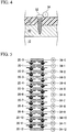
- Fig. 4 is a cross-sectional view illustrating one example of a positional relationship among one of the bus bars 20, one of the screws 32, and one of the temperature sensors 34.
- the temperature sensor 34 measures a temperature transferred via the screw 32 from the bus bar 20, that is, a temperature which can be regarded as a temperature of the bus bar 20, and outputs measurement results to a monitoring device 36.
- a temperature transferred via the screw 32 from the bus bar 20 that is, a temperature which can be regarded as a temperature of the bus bar 20, and outputs measurement results to a monitoring device 36.
- the positional relationship shown in Fig. 4 is merely one example and the temperatures of the bus bars 20 may be measured using other structures.
- the monitoring device 36 is, for example, a microcomputer. Information of temperatures measured by the temperature sensors 34 is input to the monitoring device 36. The monitoring device 36 derives temperatures of the batteries 10 on the basis of the temperatures measured by the temperature sensors 34.
- Fig. 5 is a simplified diagram of a constitution of the battery assembly system 1.
- a temperature of the positive electrode 7p in the battery assembly 5 is Ttp
- a temperature of the negative electrode 7m is Ttm
- the bus bar 20 has a temperature in which a temperature of the battery 10 connected to the bus bar 20 is uniformly reflected in the bus bar 20, it is presumed that the following simultaneous equations are established.
- T c 12 T 0 T 1 ⁇ T 11 T 12
- the monitoring device 36 performs an inverse matrix operation on a characteristic determinant represented by Expression (2) to calculate a temperature Ttave of the positive electrode 7p and the negative electrode 7m in the battery assembly 5 and an average temperature Tcn of the battery 10-nL and the battery 10-nR from temperatures Tk measured by the temperature sensors 34-k.
- the monitoring device 36 performs an inverse matrix operation by inputting the temperatures Tk measured by the temperature sensors 34-k to software information associated with the above-described inverse matrix operation already prepared in a storage device of the monitoring device 36 in a format such as, for example, a function or a table as an operand. [Math.
- the temperature sensors 34 configured to measure the temperatures of the bus bars 20 connecting the electrodes of the batteries 10 included in the battery assembly 5 and the temperatures of the bus bars 20 connecting the batteries 10 and the voltage taking-out part of the battery assembly 5, and the monitoring device 36 configured to derive the temperatures of the batteries 10 on the basis of the temperatures measured by the temperature sensors 34 are provided so that the temperatures of the batteries 10 can be derived.
- an inverse matrix operation on a characteristic determinant according to temperature transfer characteristics of the battery assembly 5 is performed so that the temperatures of the batteries 10 are derived.
- a calculating process can be simplified, and a processing load can be reduced.
- the characteristic determinant and the inverse matrix operation thereof are used so that a temperature measurement error (an offset error) due to the temperature sensors 34 can be offset.
- an inverse matrix operation is performed on a matrix based on Expressions (1) and (2) or the like and the temperatures Ttave and Tcn are acquired under the assumption that the bus bar 20 has a temperature at which the temperature of the battery 10 connected to the bus bar 20 is uniformly reflected into the bus bar 20 in the first embodiment
- an inverse matrix operation may be performed on a matrix based on an expression in which a bias is reflected so that the temperature Ttave and Tcn are acquired when the bus bar 20 does not have the temperature at which the temperature of the battery 10 connected to the bus bar 20 is uniformly reflected into the bus bar 20 in the second embodiment.
- T 0 0.7 ⁇ Ttp + 0.3 ⁇ Tc 1
- T 0 0.7 ⁇ Ttp + 0.3 ⁇ Tc 1
- T 1 0.6 ⁇ Tc 1 + 0.4 ⁇ Tc 2
- T 2 0.6 ⁇ Tc 2 + 0.4 ⁇ Tc 3
- T 3 0.5 ⁇ Tc 3 + 0.5 ⁇ Tc 4
- T 4 0.4 ⁇ Tc 4 + 0.6 ⁇ Tc 5
- T 5 0.4 ⁇ Tc 5 + 0.6 ⁇ Tc 6
- T 6 0.5 ⁇ Tc 6 + 0.5 ⁇ Tc 7
- T 7 0.6 ⁇ Tc 7 + 0.4 ⁇ Tc 8
- T 8 0.6 ⁇ Tc 8 + 0.4 ⁇ Tc 9
- T 9 0.5 ⁇ Tc 9 + 0.5 ⁇ Tc 10
- T 10 0.4 ⁇ Tc 10 + 0.6 ⁇ Tc 10 + 0.6 ⁇ T
- Ttp Ttm
- the temperatures of the batteries 10 can be derived as in the first embodiment. Furthermore, according to the second embodiment, the temperatures of the batteries 10 can be appropriately derived even when the bus bar 20 does not have a temperature at which the temperature of the battery 10 connected to the bus bar 20 is uniformly reflected into the bus bar 20.
- a temperature sensor configured to measure a board temperature
- temperatures of the batteries 10 are derived from temperatures measured by the temperature sensor are derived.
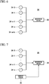
- Fig. 6 is a view illustrating a constitution showing some of constituent elements provided at a control board 30 related to the third embodiment.
- a temperature sensor 34-amb configured to measure a temperature of the control board 30 is attached to any place in addition to temperature sensors 34-0 to 34-n (n is a serial number) as in the first or second embodiments.
- the temperature sensor 34-amb measures the temperature of the control board 30 and outputs measurement results to a monitoring device 36.
- T 0 ⁇ 1 ⁇ 0 , 5 ⁇ Ttp + Tc 1 + ⁇ 2 ⁇ Tamb
- T 1 ⁇ 1 ⁇ 0.5 ⁇ Tc 1 + Tc 2 + ⁇ 2 ⁇ Tamb .
- Tn ⁇ 1 ⁇ 1 ⁇ 0.5 ⁇ Tc n ⁇ 1 + Tcn + ⁇ 2 ⁇ Tamb
- Tn ⁇ 1 ⁇ 0.5 ⁇ Tcn + Ttm + ⁇ 2 ⁇ Tamb
- the characteristic determinant is represented by, for example, Expression (6).
- the monitorer 36 related to the third embodiment performs, for example, an inverse matrix operation of a characteristic determinant (6) to acquire temperatures Ttave and Tcn.
- ⁇ 1 0.5 0.5 ⁇ 0 0 0 0.5 ⁇ 0 0 ⁇ ⁇ ⁇ ⁇ ⁇ 0 0 ⁇ 0.5 0.5 0.5 0 ⁇ 0 0.5 T tave T c 1 ⁇ T c 11 T c 12 + ⁇ 2 T amb T amb ⁇ T amb T amb T 0 T 1 ⁇ T 11 T 12
- an influence on the batteries 10 due to the temperature of the control board 30 is not uniform, and may be different for each battery 10. If the influence on the batteries 10 due to the temperature of the control board 30 varies when the serial number is 4, the characteristic determinant is represented by, for example, Expression (7). An inverse matrix in this case is represented by Expression (8). [Math.
- the temperatures of the batteries 10 can be derived as in the first embodiment. Furthermore, according to the third embodiment, the influence due to the temperature of the control board 30 is subtracted so that the temperatures of the batteries 10 are derived. Thus, the temperatures of the batteries 10 can be more accurately derived.
- temperatures of batteries 10 as well as an assumed generated heat value due to a current flowing through bus bars 20 are derived.
- Fig. 7 is a view illustrating a constitution showing some of constituent elements provided at a control board 30 related to the fourth embodiment.
- a current sensor (a current detector) 38 is provided at any place on a power path connected to a positive electrode 7p or a negative electrode 7m of a battery assembly 5. Note that the current sensor 38 may be provided at other places which are not on the control board 30.
- the current sensor 38 detects a current value with which the battery assembly 5 is charged and which is discharged from the battery assembly 5, and outputs detection results to the monitoring device 36.
- a characteristic determinant is represented by, for example, Expression (9).
- the monitoring device 36 related to the third embodiment acquires temperatures Ttave and Tcn, for example, by performing an inverse matrix operation on a characteristic determinant (9).
- the temperatures of the batteries 10 can be derived as in the first embodiment. Furthermore, according to the fourth embodiment, an influence given to the temperature of the batteries 10 by a current value with which the battery assembly 5 is charged and which is discharged from the battery assembly 5 is added so that the temperatures of the batteries 10 are derived. Thus, the temperatures of the batteries 10 can be more accurately derived.
- temperatures of batteries 10 as well as resistance values of balance resistors for suppressing a variation of voltages of the batteries 10 are derived.
- the balance resistors are provided, for example, on a control board 30. Furthermore, a disposition and resistance values of the balance resistors are known, and are stored in a storage device of a monitoring device 36.
- a characteristic determinant is represented by, for example, Expression (12).
- the monitoring device 36 related to the fifth embodiment acquires temperatures Ttave and Tcn, for example, by performing an inverse matrix operation on a characteristic determinant (12).
- balance discharge circuits are partially fixed, and calculation is performed in proportion to the number of cells to be discharged.
- an influence of discharge can also be checked for each bus bar 20.
- the balance resistors influence the bus bars 20 as a matrix so that the temperatures Ttave and Tcn can be acquired.
- a characteristic determinant in this case is represented by, for example, Expression (15).
- an inverse matrix of a characteristic determinant (15) is represented by Expression (16). [Math.
- the temperatures of the batteries 10 can be derived as in the first embodiment. Furthermore, according to the fifth embodiment, the temperatures of the batteries 10 are derived by subtracting the influence due to the balance resistors. Thus, the temperatures of the batteries 10 can be more accurately derived.
- a battery assembly system and a control board of a battery assembly related to a sixth embodiment will be described.
- a positive electrode 7p and a negative electrode 7m of a battery assembly 5 serve as temperature monitoring targets and a temperature monitoring target in which an abnormality has occurred among batteries 10 is extracted on the basis of a difference between temperatures calculated with respect to temperature monitoring targets which are adjacent to each other.
- the processes are performed under the assumption that temperatures of the positive electrode 7p and the negative electrode 7m of the battery assembly 5 are the same, but in the sixth embodiment, it can be determined whether abnormality occurs in any of the positive electrode 7p and the negative electrode 7m of the battery assembly 5.
- a temperature Ttp of the positive electrode 7p in the battery assembly 5 increases 20 °C.
- An inverse matrix of a characteristic determinant has characteristics in which a positive value or a negative value alternately appears in each row.
- a result value with a positive influence and a result value with a negative influence alternately appear with respect to a change in temperature.
- the fact that the positive and negative influence not appearing is limited to calculation results in the vicinity of a position at which a change in temperature occurs. In the example of Fig. 8 , only a difference between temperatures Ttp and Tc1 serving as a calculation result does not cause a difference between neighboring calculation results.
- a monitoring device 36 related to the sixth embodiment extracts temperatures Ttp and Tc1 in which a difference does not occur between neighboring calculation results, and determines that there is abnormality in any of the positive electrode 7p, the bus bar 20-0, batteries 10-1 L, and 10-1 R in the battery assembly 5 involved in the extracted temperatures.
- the monitoring device 36 transmits a signal used to display a place for which there is determined to be an abnormality to, for example, a display device (not shown) in a wired or wireless manner.
- a place at which abnormality occurs can be appropriately extracted, and support is performed so that abnormality can be found early.
- a monitoring device 36 may decrease monitoring resolution so that a process transitions to a rough monitoring process when abnormality occurs in any of the temperature sensors 34.
- a battery assembly 5 in which a plurality of batteries 10 are connected in series, temperature sensors 34 configured to measure temperatures of connection parts 20 used to connect electrodes of the batteries 10 are included in the battery assembly 5, and a monitoring device 36 is configured to derive temperatures of the batteries 10 on the basis of the temperatures measured by the temperature sensors 34 is provided so that the temperatures of the batteries 10 constituting the battery assembly 5 can be derived.
Landscapes
- Engineering & Computer Science (AREA)
- Chemical & Material Sciences (AREA)
- Manufacturing & Machinery (AREA)
- Chemical Kinetics & Catalysis (AREA)
- Electrochemistry (AREA)
- General Chemical & Material Sciences (AREA)
- Physics & Mathematics (AREA)
- General Physics & Mathematics (AREA)
- Materials Engineering (AREA)
- Secondary Cells (AREA)
- Charge And Discharge Circuits For Batteries Or The Like (AREA)
- Battery Mounting, Suspending (AREA)
Abstract
Description
- An embodiment of the present invention relates to a battery assembly system and a control board for a battery assembly.
- In the related art, a battery assembly in which a plurality of batteries are connected is known. It is important in deriving states of the batteries to ascertain temperatures of the batteries constituting the battery assembly. However, directly or indirectly, it is difficult to measure the temperatures of the batteries constituting the battery assembly. Also, in the related art, the temperatures of the batteries cannot be appropriately derived on the basis of the temperatures, which are indirectly measured, in some cases.
-
- [Patent Literature 1] Japanese Unexamined Patent Application, First Publication No.
2010-220323 - An object to be accomplished by the present invention is to provide a battery assembly system and a control board of a battery assembly which can derive temperatures of batteries constituting a battery assembly.
- A battery assembly system of an embodiment includes: a battery assembly; a temperature measuring part; and a monitorer. The battery assembly includes a plurality of batteries connected in series. The temperature measuring part measures temperatures of connection parts used to connect electrodes of batteries included in the battery assembly. The monitorer derives temperatures of the batteries on the basis of the temperatures measured by the temperature measuring part.
-
-
Fig. 1 is an exploded perspective view showing an overall constitution of abattery assembly system 1 related to a first embodiment. -
Fig. 2 is a view illustrating onebattery 10. -
Fig. 3 is a top view of abattery assembly 5. -
Fig. 4 is a cross-sectional view illustrating one example of a positional relationship among abus bar 20, ascrew 32, and atemperature sensor 34. -
Fig. 5 is a simplified diagram of a constitution of thebattery assembly system 1. -
Fig. 6 is a view illustrating a constitution showing some of constituent elements provided at acontrol board 30 related to a third embodiment. -
Fig. 7 is a view illustrating a constitution showing some of constituent elements provided at thecontrol board 30 related to a fourth embodiment. -
Fig. 8 is a view simply illustrating an influence of a temperature rise. - Hereinafter, a battery assembly system and a control board of a battery assembly in an embodiment will be described with reference to the drawings.
-
Fig. 1 is an exploded perspective view showing an overall constitution of abattery assembly system 1 related to a first embodiment. Furthermore,Fig. 2 is a view illustrating onebattery 10.Fig. 3 is a top view of a battery assembly 5 (only onepositive electrode 7p and onenegative electrode 7m of theentire battery assembly 5 are illustrated as in a bird's eye view). - The
battery assembly system 1 includes, for example, thebattery assembly 5 including batteries (cells) 10-1L and 10-1R to 10-12L and 10-12R and acontrol board 30. Batteries, in which numbers after hyphens are the same and letter parts after the hyphens such as L and R differ, are connected in parallel with each other and used such as a battery 10-1L and a battery 10-1R and a battery 10-2L and a battery 10-2R in thebattery assembly 5. Hereinafter, when batteries need not be distinguished from each other, they are referred to simply asbatteries 10. - The
batteries 10 are, for example, preferably lithium ion batteries in which manganese is used for a positive electrode and lithium titanate is used for a negative electrode. A rate of receiving charge can be improved and a likelihood of an internal short circuit being caused due to precipitation of lithium can be decreased by adopting such a configuration for thebatteries 10. In the case of thebatteries 10, a plurality of structures, in which positive electrodes and negative electrodes face each other with separators interposed therebetween, are stacked, and as shown inFig. 2 , a positive electrode terminal P connected to the plurality of positive electrodes, a negative electrode terminal N connected to the plurality of negative electrodes, and a gas exhaust valve are provided at a casing surface. Furthermore, each of thebatteries 10 may be a lithium ion battery in which a lithium metal oxide is used for each of the positive electrodes and a carbon material such as graphite is used for each of the negative electrodes, and may be a battery of another aspect such as a lead storage battery. - The
batteries 10 are connected to each other using bus bars (connection parts). A bus bar 20-0 connects thepositive electrode 7p (a voltage taking-out part at the positive electrode) for theentire battery assembly 5 and positive electrodes of the battery 10-1L and the battery 10-1R. A bus bar 20-1 connects negative electrodes of the battery 10-1L and the battery 10-1R and positive electrodes of the battery 10-2L and the battery 10-2R. A bus bar 20-2 connects negative electrodes of the battery 10-2L and the battery 10-2R and positive electrodes of a battery 10-3L and a battery 10-3R. A bus bar 20-3 connects negative electrodes of the battery 10-3L and the battery 10-3R and positive electrodes of a battery 10-4L and a battery 10-4R. A bus bar 20-4 connects negative electrodes of the battery 10-4L and the battery 10-4R and positive electrodes of a battery 10-5L and a battery 10-5R. A bus bar 20-5 connects negative electrodes of the battery 10-5L and the battery 10-5R and positive electrodes of a battery 10-6L and a battery 10-6R. A bus bar 20-6 connects negative electrodes of the battery 10-6L and the battery 10-6R and positive electrodes of a battery 10-7L and a battery 10-7R. A bus bar 20-7 connects negative electrodes of the battery 10-7L and the battery 10-7R and positive electrodes of a battery 10-8L and a battery 10-8R. A bus bar 20-8 connects negative electrodes of the battery 10-8L and the battery 10-8R and positive electrodes of a battery 10-9L and a battery 10-9R. A bus bar 20-9 connects negative electrodes of the battery 10-9L and the battery 10-9R and positive electrodes of a battery 10-10L and a battery 10-10R. A bus bar 20-10 connects negative electrodes of the battery 10-10L and the battery 10-10R and positive electrodes of a battery 10-11 L and a battery 10-11 R. A bus bar 20-11 connects negative electrodes of the battery 10-11L and the battery 10-11R and positive electrodes of a battery 10-12L and a battery 10-12R. A bus bar 20-12 connects negative electrodes of the battery 10-12L and the battery 10-12R and thenegative electrode 7m (a voltage taking-out part at the negative electrode) for theentire battery assembly 5. With such a connection structure, thebattery assembly 5 is constituted as a battery assembly in which 2 batteries are in parallel and 12 batteries are in series. Hereinafter, when the bus bars need not be distinguished from each other, they are referred to simply asbus bars 20. - For example, the bus bars 20-0 to 20-12 are secured to the
control board 30 using screws (or bolts or the like) 32-0 to 32-12. Temperature sensors 34-0 to 34-12 are attached to the screws 32-0 to 32-12 as a temperature measuring part. Hereinafter, when the screws and the temperature sensors need not be distinguished from each other, they are referred to simply asscrews 32 andtemperature sensors 34, respectively.Fig. 4 is a cross-sectional view illustrating one example of a positional relationship among one of thebus bars 20, one of thescrews 32, and one of thetemperature sensors 34. With such a structure, thetemperature sensor 34 measures a temperature transferred via thescrew 32 from thebus bar 20, that is, a temperature which can be regarded as a temperature of thebus bar 20, and outputs measurement results to amonitoring device 36. Note that the positional relationship shown inFig. 4 is merely one example and the temperatures of thebus bars 20 may be measured using other structures. - The
monitoring device 36 is, for example, a microcomputer. Information of temperatures measured by thetemperature sensors 34 is input to themonitoring device 36. Themonitoring device 36 derives temperatures of thebatteries 10 on the basis of the temperatures measured by thetemperature sensors 34. - Hereinafter, a temperature monitoring method using the
monitoring device 36 will be described.Fig. 5 is a simplified diagram of a constitution of thebattery assembly system 1. Hereinafter, a temperature measured by a temperature sensor 34-k (k = 0 to 12) is referred to as Tk (k = 0 to 12). Here, if it is estimated that a temperature of thepositive electrode 7p in thebattery assembly 5 is Ttp, a temperature of thenegative electrode 7m is Ttm, an average temperature of a battery 10-nL and a battery 10-nR (n = 1 to 12) is Tcn, and thebus bar 20 has a temperature in which a temperature of thebattery 10 connected to thebus bar 20 is uniformly reflected in thebus bar 20, it is presumed that the following simultaneous equations are established.



- Here, if there is no particular abnormality in the
battery assembly 5, a temperature Ttp of thepositive electrode 7p and a temperature Ttm of thenegative electrode 7m in thebattery assembly 5 depend on a current with which thebattery assembly 5 is charged and which is discharged from thebattery assembly 5. Thus, these temperatures can be regarded as the same. If temperature Ttp = temperature Ttm = temperature Ttave is satisfied, an unknown number in the above-described simultaneous equations is 12. Thus, the temperature Tcn can be calculated. Furthermore, the simultaneous equations can be represented by a characteristic determinant of Expression (1).
[Math. 1]
- The
monitoring device 36 performs an inverse matrix operation on a characteristic determinant represented by Expression (2) to calculate a temperature Ttave of thepositive electrode 7p and thenegative electrode 7m in thebattery assembly 5 and an average temperature Tcn of the battery 10-nL and the battery 10-nR from temperatures Tk measured by the temperature sensors 34-k. Themonitoring device 36 performs an inverse matrix operation by inputting the temperatures Tk measured by the temperature sensors 34-k to software information associated with the above-described inverse matrix operation already prepared in a storage device of themonitoring device 36 in a format such as, for example, a function or a table as an operand.
[Math. 2]
- Note that, when abnormality occurs in any of the
temperature sensors 34, a phenomenon in which "values of Ttp and Ttm significantly differ" or a "calculated value of Tc1 or Tc12 is an abnormal value" occurs. Thus, abnormality of thetemperature sensors 34 can also be detected. - According to the battery assembly system and the control board of the battery assembly, which have been described above, related to the first embodiment, the
temperature sensors 34 configured to measure the temperatures of the bus bars 20 connecting the electrodes of thebatteries 10 included in thebattery assembly 5 and the temperatures of the bus bars 20 connecting thebatteries 10 and the voltage taking-out part of thebattery assembly 5, and themonitoring device 36 configured to derive the temperatures of thebatteries 10 on the basis of the temperatures measured by thetemperature sensors 34 are provided so that the temperatures of thebatteries 10 can be derived. - Also, according to the first embodiment, an inverse matrix operation on a characteristic determinant according to temperature transfer characteristics of the
battery assembly 5 is performed so that the temperatures of thebatteries 10 are derived. Thus, a calculating process can be simplified, and a processing load can be reduced. - According to the first embodiment, the characteristic determinant and the inverse matrix operation thereof are used so that a temperature measurement error (an offset error) due to the
temperature sensors 34 can be offset. - Hereinafter, a battery assembly system and a control board of a battery assembly related to a second embodiment will be described. Although it is assumed that an inverse matrix operation is performed on a matrix based on Expressions (1) and (2) or the like and the temperatures Ttave and Tcn are acquired under the assumption that the
bus bar 20 has a temperature at which the temperature of thebattery 10 connected to thebus bar 20 is uniformly reflected into thebus bar 20 in the first embodiment, an inverse matrix operation may be performed on a matrix based on an expression in which a bias is reflected so that the temperature Ttave and Tcn are acquired when thebus bar 20 does not have the temperature at which the temperature of thebattery 10 connected to thebus bar 20 is uniformly reflected into thebus bar 20 in the second embodiment. - For example, when the temperature of the bus bar 20-0 is more significantly affected by the temperature of the
positive electrode 7p in thebattery assembly 5 than the battery 10-1L and the battery 10-1R due to an attachment position, a size, a shape, or the like of the bus bar 20-0, a tendency thereof can be expressed in the following equation.
- Similarly, when the temperatures of the bus bars 20 are significantly affected by the temperatures of some of the connected
batteries 10 due to attachment positions, sizes, shapes, or the like of the bus bars 20, for example, it can be estimated that the following simultaneous equations will be established.


- The
monitorer 36 related to the second embodiment takes into account, for example, the above-described simultaneous equations, and the temperatures Ttave and Tcn are acquired by performing an inverse matrix operation on a characteristic determinant (3) established when Ttp = Ttm is assumed.
[Math. 3]
- Note that, when a serial number is 4, the characteristic determinant is represented by, for example, Expression (4). An inverse matrix of a characteristic determinant (4) is represented by Expression (5).
[Math. 4]

- According to the battery assembly system and the control board of the battery assembly, which have been described above, related to the second embodiment, the temperatures of the
batteries 10 can be derived as in the first embodiment. Furthermore, according to the second embodiment, the temperatures of thebatteries 10 can be appropriately derived even when thebus bar 20 does not have a temperature at which the temperature of thebattery 10 connected to thebus bar 20 is uniformly reflected into thebus bar 20. - Hereinafter, a battery assembly system and a control board of a battery assembly related to a third embodiment will be described. In the third embodiment, a temperature sensor configured to measure a board temperature is provided, and temperatures of the
batteries 10 are derived from temperatures measured by the temperature sensor are derived.Fig. 6 is a view illustrating a constitution showing some of constituent elements provided at acontrol board 30 related to the third embodiment. As shown in the drawing, in the case of thecontrol board 30, a temperature sensor 34-amb configured to measure a temperature of thecontrol board 30 is attached to any place in addition to temperature sensors 34-0 to 34-n (n is a serial number) as in the first or second embodiments. The temperature sensor 34-amb measures the temperature of thecontrol board 30 and outputs measurement results to amonitoring device 36. - In this embodiment, when the
bus bar 20 has the temperature at which the temperature of thebattery 10 connected to thebus bar 20 is uniformly reflected into thebus bar 20 as in the first embodiment, the following simultaneous equations are estimated to be established. In the expression, α1 and α2 are coefficients obtained through experiments or the like, and for example, are set such that α1 + α2 = 1 is satisfied.
- In this case, the characteristic determinant is represented by, for example, Expression (6). The
monitorer 36 related to the third embodiment performs, for example, an inverse matrix operation of a characteristic determinant (6) to acquire temperatures Ttave and Tcn.
[Math. 5]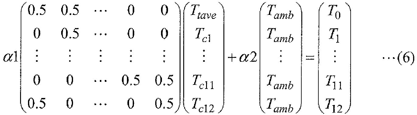
- Note that an influence on the
batteries 10 due to the temperature of thecontrol board 30 is not uniform, and may be different for eachbattery 10. If the influence on thebatteries 10 due to the temperature of thecontrol board 30 varies when the serial number is 4, the characteristic determinant is represented by, for example, Expression (7). An inverse matrix in this case is represented by Expression (8).
[Math. 6]

- According to the battery assembly system and the control board of the battery assembly, which have been described above, related to the third embodiment, the temperatures of the
batteries 10 can be derived as in the first embodiment. Furthermore, according to the third embodiment, the influence due to the temperature of thecontrol board 30 is subtracted so that the temperatures of thebatteries 10 are derived. Thus, the temperatures of thebatteries 10 can be more accurately derived. - Hereinafter, a battery assembly system and a control board of a battery assembly related to a fourth embodiment will be described. In the fourth embodiment, temperatures of
batteries 10 as well as an assumed generated heat value due to a current flowing throughbus bars 20 are derived. -
Fig. 7 is a view illustrating a constitution showing some of constituent elements provided at acontrol board 30 related to the fourth embodiment. A current sensor (a current detector) 38 is provided at any place on a power path connected to apositive electrode 7p or anegative electrode 7m of abattery assembly 5. Note that thecurrent sensor 38 may be provided at other places which are not on thecontrol board 30. Thecurrent sensor 38 detects a current value with which thebattery assembly 5 is charged and which is discharged from thebattery assembly 5, and outputs detection results to themonitoring device 36. - In this embodiment, when it is assumed that a current flowing through the bus bars 20 is I and the bus bars 20 have temperatures in which temperatures of the
batteries 10 connected to the bus bars 20 are uniformly reflected into the bus bars 20 as in the first embodiment, the following simultaneous equations are estimated to be established. In the expressions, β0 to βn are coefficients based on a resistance value for eachbus bar 20, and R is a reference resistance value.
- In the case, a characteristic determinant is represented by, for example, Expression (9). The
monitoring device 36 related to the third embodiment acquires temperatures Ttave and Tcn, for example, by performing an inverse matrix operation on a characteristic determinant (9).
[Math. 7]
- Note that, when a serial number is 4, the characteristic determinant is represented by, for example, Expression (10). An inverse matrix of a characteristic determinant (10) is represented by Expression (11).
[Math. 8]

- According to the battery assembly system and the control board of the battery assembly, which have been described above, related to the fourth embodiment, the temperatures of the
batteries 10 can be derived as in the first embodiment. Furthermore, according to the fourth embodiment, an influence given to the temperature of thebatteries 10 by a current value with which thebattery assembly 5 is charged and which is discharged from thebattery assembly 5 is added so that the temperatures of thebatteries 10 are derived. Thus, the temperatures of thebatteries 10 can be more accurately derived. - Hereinafter, a battery assembly system and a control board of a battery assembly related to a fifth embodiment will be described. In the fifth embodiment, temperatures of
batteries 10 as well as resistance values of balance resistors for suppressing a variation of voltages of thebatteries 10 are derived. The balance resistors are provided, for example, on acontrol board 30. Furthermore, a disposition and resistance values of the balance resistors are known, and are stored in a storage device of amonitoring device 36. - In this embodiment, when bus bars 20 have temperatures in which temperatures of the
batteries 10 connected to the bus bars 20 are uniformly reflected into the bus bars 20 as in the first embodiment, the following simultaneous equations are estimated to be established. In the expression, γ0 to γn are coefficients of an influence on bus bar temperature due to balance discharge, and Ncell is the number of thebatteries 10 in which balance discharge is performed
- In this case, a characteristic determinant is represented by, for example, Expression (12). The
monitoring device 36 related to the fifth embodiment acquires temperatures Ttave and Tcn, for example, by performing an inverse matrix operation on a characteristic determinant (12).
[Math. 9]
- Note that, when a serial number is 4, the characteristic determinant is represented by, for example, Expression (13). An inverse matrix of a characteristic determinant (13) is represented by Expression (14).
[Math. 10]

- Also, in the above-described example, a case in which balance discharge circuits are partially fixed is assumed, and calculation is performed in proportion to the number of cells to be discharged. Here, when the balance discharge circuits are distributed in an entire circuit, an influence of discharge can also be checked for each
bus bar 20. For example, when discharging parts are distributed, the balance resistors influence the bus bars 20 as a matrix so that the temperatures Ttave and Tcn can be acquired. A characteristic determinant in this case is represented by, for example, Expression (15). Furthermore, an inverse matrix of a characteristic determinant (15) is represented by Expression (16).
[Math. 11]

- According to the battery assembly system and the control board of the battery assembly, which have been described above, related to the fifth embodiment, the temperatures of the
batteries 10 can be derived as in the first embodiment. Furthermore, according to the fifth embodiment, the temperatures of thebatteries 10 are derived by subtracting the influence due to the balance resistors. Thus, the temperatures of thebatteries 10 can be more accurately derived. - Hereinafter, a battery assembly system and a control board of a battery assembly related to a sixth embodiment will be described. In the sixth embodiment, a
positive electrode 7p and anegative electrode 7m of abattery assembly 5 serve as temperature monitoring targets and a temperature monitoring target in which an abnormality has occurred amongbatteries 10 is extracted on the basis of a difference between temperatures calculated with respect to temperature monitoring targets which are adjacent to each other. In the first to fifth embodiments, the processes are performed under the assumption that temperatures of thepositive electrode 7p and thenegative electrode 7m of thebattery assembly 5 are the same, but in the sixth embodiment, it can be determined whether abnormality occurs in any of thepositive electrode 7p and thenegative electrode 7m of thebattery assembly 5. - An inverse matrix of Expression (2) will be described as an example. For example, when a temperature of the
positive electrode 7p of thebattery assembly 5 rises due to loosening of a terminal or the like, this temperature rise appears as a temperature rise of a bus bar 20-0. In this case, according to Expression (2), temperatures Ttave and Tc1 both increase, however, other than the relation of the temperatures Ttave and Tc1, alternating opposite effects appear such as a temperature Tc2 decreasing, a temperature Tc3 increasing, a temperature Tc4 decreasing, and a temperature Tc5 increasing.Fig. 8 is a view simply illustrating an influence of a temperature rise. In an example ofFig. 8 , it is assumed that a temperature Ttp of thepositive electrode 7p in thebattery assembly 5increases 20 °C. An inverse matrix of a characteristic determinant has characteristics in which a positive value or a negative value alternately appears in each row. Thus, as shown inFig. 8 , in the case of calculation results, a result value with a positive influence and a result value with a negative influence alternately appear with respect to a change in temperature. Also, the fact that the positive and negative influence not appearing is limited to calculation results in the vicinity of a position at which a change in temperature occurs. In the example ofFig. 8 , only a difference between temperatures Ttp and Tc1 serving as a calculation result does not cause a difference between neighboring calculation results. Amonitoring device 36 related to the sixth embodiment extracts temperatures Ttp and Tc1 in which a difference does not occur between neighboring calculation results, and determines that there is abnormality in any of thepositive electrode 7p, the bus bar 20-0, batteries 10-1 L, and 10-1 R in thebattery assembly 5 involved in the extracted temperatures. Themonitoring device 36 transmits a signal used to display a place for which there is determined to be an abnormality to, for example, a display device (not shown) in a wired or wireless manner. - According to the battery assembly system and the control board of the battery assembly, which have been described above, related to the sixth embodiment, a place at which abnormality occurs can be appropriately extracted, and support is performed so that abnormality can be found early.
- The above-described processes of the embodiments can be appropriately combined. For example, in the third embodiment, calculation corresponding to a case in which a
bus bar 20 does not have a temperature in which a temperature of abattery 10 connected to thebus bar 20 is uniformly reflected in thebus bar 20 may be performed as in the second embodiment. Furthermore, the process related to the sixth embodiment can be applied to the processes of the second to fifth embodiments as well as that of the first embodiment. - Also, a
monitoring device 36 may decrease monitoring resolution so that a process transitions to a rough monitoring process when abnormality occurs in any of thetemperature sensors 34. - According to at least one embodiment described above, a
battery assembly 5 in which a plurality ofbatteries 10 are connected in series,temperature sensors 34 configured to measure temperatures ofconnection parts 20 used to connect electrodes of thebatteries 10 are included in thebattery assembly 5, and amonitoring device 36 is configured to derive temperatures of thebatteries 10 on the basis of the temperatures measured by thetemperature sensors 34 is provided so that the temperatures of thebatteries 10 constituting thebattery assembly 5 can be derived. - Although some embodiments of the present invention have been described, these embodiments are presented as examples, and are not intended to limit the scope of the present invention. These embodiments can be carried out in various other forms. In addition, various omissions, substitutions, or changes can be performed without departing from the gist of the present invention. These embodiments and modifications thereof are included in the scope or the gist of the present invention and are included in the scope of the appended claims and the equivalent scope thereof.
Claims (8)
- A battery assembly system comprising:a battery assembly in which a plurality of batteries are connected in series;a temperature measuring part configured to measure temperatures of connection parts used to connect electrodes of batteries included in the battery assembly; anda monitoring device configured to derive temperatures of the batteries on the basis of the temperatures measured by the temperature measuring part.
- The battery assembly system according to claim 1, wherein the measuring part further measures temperatures of connection parts used to connect the batteries included in the battery assembly and a voltage taking-out part of the battery assembly.
- The battery assembly system according to claim 1 or 2, wherein the monitoring device solves simultaneous equations based on an extent to which the connection parts have temperatures in which the temperatures of the batteries connected to the connection parts or the temperature of the voltage taking-out part of the battery assembly is reflected in the connection parts to derive temperatures of the batteries.
- The battery assembly system according to claim 3, wherein the monitoring device performs an inverse matrix operation when the simultaneous equations are set as a determinant to derive temperatures of the batteries.
- The battery assembly system according to claim 1, wherein the temperature measuring part is provided on a control board attached to the battery assembly and further measures a temperature of the control board, and
the monitoring device subtracts a value based on the temperature of the control board measured by the temperature measuring part to derive temperatures of the batteries. - The battery assembly system to claim 1, comprising:a current detector configured to detect a current with which the battery assembly is charged and which is discharged from the battery assembly,wherein the monitoring device adds values obtained by multiplying currents detected by the current detector by resistance values of the batteries to derive temperatures of the batteries.
- The battery assembly system to claim 1, wherein the monitoring device extracts a place at which a difference between results for batteries connected in series and adjacent to each other in the battery assembly is small among results in which the temperatures of the batteries are derived, and determines that abnormality occurs in a battery associated with the extracted place.
- A control board of a battery assembly attached to a battery assembly in which a plurality of batteries are connected in series, the control board of the battery assembly comprising:a temperature measuring part configured to measure temperatures of connection parts used to connect electrodes of batteries included in the battery assembly; anda monitoring device configured to derive temperatures of the batteries on the basis of the temperatures measured by the temperature measuring part.
Applications Claiming Priority (2)
| Application Number | Priority Date | Filing Date | Title |
|---|---|---|---|
| JP2014148341 | 2014-07-18 | ||
| PCT/JP2015/061351 WO2016009687A1 (en) | 2014-07-18 | 2015-04-13 | Battery pack system and battery pack control board |
Publications (2)
| Publication Number | Publication Date |
|---|---|
| EP3171447A1 true EP3171447A1 (en) | 2017-05-24 |
| EP3171447A4 EP3171447A4 (en) | 2018-04-25 |
Family
ID=55078192
Family Applications (1)
| Application Number | Title | Priority Date | Filing Date |
|---|---|---|---|
| EP15821931.1A Withdrawn EP3171447A4 (en) | 2014-07-18 | 2015-04-13 | Battery pack system and battery pack control board |
Country Status (5)
| Country | Link |
|---|---|
| US (1) | US20170200987A1 (en) |
| EP (1) | EP3171447A4 (en) |
| JP (1) | JPWO2016009687A1 (en) |
| CN (1) | CN106663849A (en) |
| WO (1) | WO2016009687A1 (en) |
Families Citing this family (5)
| Publication number | Priority date | Publication date | Assignee | Title |
|---|---|---|---|---|
| CN109070295B (en) * | 2016-03-28 | 2020-10-27 | 斗山机床株式会社 | Automatic conversion device and conversion method for thermal displacement compensation parameters of machine tool |
| WO2017187518A1 (en) * | 2016-04-26 | 2017-11-02 | 株式会社 東芝 | Storage battery device |
| JP7167116B2 (en) * | 2020-12-01 | 2022-11-08 | プライムプラネットエナジー&ソリューションズ株式会社 | Estimation system, estimation device, power supply, and estimation method |
| EP4455701B1 (en) * | 2021-12-24 | 2026-02-04 | Denso Corporation | Battery monitoring device, battery transport apparatus, and battery monitoring method |
| JP2024102726A (en) * | 2023-01-19 | 2024-07-31 | 株式会社Gsユアサ | POWER STORAGE DEVICE, MANAGEMENT DEVICE, METHOD FOR ESTIMATING TEMPERATURE OF POWER STORAGE ELEMENT, AND COMPUTER PROGRAM |
Family Cites Families (8)
| Publication number | Priority date | Publication date | Assignee | Title |
|---|---|---|---|---|
| JP4121511B2 (en) * | 2004-03-30 | 2008-07-23 | 三洋電機株式会社 | Power supply |
| JP5159498B2 (en) * | 2008-07-29 | 2013-03-06 | 三洋電機株式会社 | Charge / discharge control method for battery in power supply device of hybrid car |
| JP2010257775A (en) * | 2009-04-24 | 2010-11-11 | Sanyo Electric Co Ltd | Battery module, battery system and electric vehicle |
| JP5347186B2 (en) * | 2010-04-26 | 2013-11-20 | 株式会社小松製作所 | Temperature detecting method and apparatus for power storage device, and temperature detecting device for power storage device in hybrid construction machine |
| US8427171B2 (en) * | 2010-06-07 | 2013-04-23 | Steve Carkner | Battery connection failure detection system |
| JP2013137905A (en) * | 2011-12-28 | 2013-07-11 | Aisan Ind Co Ltd | Monitoring device of battery pack |
| JP6031791B2 (en) * | 2012-03-28 | 2016-11-24 | 三菱自動車工業株式会社 | Battery abnormality determination device |
| US20150103866A1 (en) * | 2013-10-11 | 2015-04-16 | Qualcomm Incorporated | DIGITAL TEMPERATURE ESTIMATORS (DTEs) DISPOSED IN INTEGRATED CIRCUITS (ICs) FOR ESTIMATING TEMPERATURE WITHIN THE ICs, AND RELATED SYSTEMS AND METHODS |
-
2015
- 2015-04-13 WO PCT/JP2015/061351 patent/WO2016009687A1/en not_active Ceased
- 2015-04-13 EP EP15821931.1A patent/EP3171447A4/en not_active Withdrawn
- 2015-04-13 CN CN201580038604.8A patent/CN106663849A/en not_active Withdrawn
- 2015-04-13 JP JP2016534297A patent/JPWO2016009687A1/en active Pending
- 2015-04-13 US US15/326,855 patent/US20170200987A1/en not_active Abandoned
Also Published As
| Publication number | Publication date |
|---|---|
| EP3171447A4 (en) | 2018-04-25 |
| CN106663849A (en) | 2017-05-10 |
| JPWO2016009687A1 (en) | 2017-06-01 |
| US20170200987A1 (en) | 2017-07-13 |
| WO2016009687A1 (en) | 2016-01-21 |
Similar Documents
| Publication | Publication Date | Title |
|---|---|---|
| CN103630843B (en) | Battery status estimating unit and estimation method, battery control device, battery system | |
| CN108414941B (en) | Method and apparatus for monitoring the temperature of a battery system | |
| US10955479B2 (en) | Battery control device | |
| US8635038B2 (en) | System for monitoring the state of a battery | |
| US20210318386A1 (en) | Management device and power supply system | |
| RU2524050C1 (en) | Assessment device of accumulator state, and assessment method of accumulator state | |
| EP3410139B1 (en) | Method for estimating the current and the state of charge of a battery pack or cell, without direct detection of current under operating conditions | |
| US12119695B2 (en) | Device and method for detecting poor battery cell | |
| US20170200987A1 (en) | Battery assembly system and control board for battery assembly | |
| JP2001095160A (en) | Abnormal battery cell detection method | |
| JP5812968B2 (en) | Current sensor failure detection device, battery system, and current sensor failure detection method | |
| CN116391132A (en) | Detection method for detecting defects of a module group of batteries | |
| JP2020051863A (en) | Device for determining failure of current sensor | |
| CN105866551A (en) | Method for detecting internal resistance of sodium-sulfur battery | |
| JP2017022852A (en) | Power storage device and power storage method | |
| CN102735898A (en) | Battery voltage detector | |
| KR102757601B1 (en) | Apparatus and method for diagnosing the effectiveness of battery cell balancing | |
| CN110031715A (en) | The method of internal short-circuit in first electric flux memory cell for identification | |
| JP6018169B2 (en) | Storage device failure determination method | |
| JP5886225B2 (en) | Battery control device and battery control method | |
| US11408776B2 (en) | Power supply device, and method for detecting opening of exhaust valve of power supply device | |
| JP6485439B2 (en) | Power storage system | |
| JP2021153008A (en) | Heat chain monitoring device | |
| JP2003257504A (en) | Overdischarge detection method for secondary batteries | |
| KR102920622B1 (en) | Method for managing battery banks and battery system using the same |
Legal Events
| Date | Code | Title | Description |
|---|---|---|---|
| STAA | Information on the status of an ep patent application or granted ep patent |
Free format text: STATUS: THE INTERNATIONAL PUBLICATION HAS BEEN MADE |
|
| PUAI | Public reference made under article 153(3) epc to a published international application that has entered the european phase |
Free format text: ORIGINAL CODE: 0009012 |
|
| STAA | Information on the status of an ep patent application or granted ep patent |
Free format text: STATUS: REQUEST FOR EXAMINATION WAS MADE |
|
| 17P | Request for examination filed |
Effective date: 20170117 |
|
| AK | Designated contracting states |
Kind code of ref document: A1 Designated state(s): AL AT BE BG CH CY CZ DE DK EE ES FI FR GB GR HR HU IE IS IT LI LT LU LV MC MK MT NL NO PL PT RO RS SE SI SK SM TR |
|
| AX | Request for extension of the european patent |
Extension state: BA ME |
|
| DAV | Request for validation of the european patent (deleted) | ||
| DAX | Request for extension of the european patent (deleted) | ||
| A4 | Supplementary search report drawn up and despatched |
Effective date: 20180326 |
|
| RIC1 | Information provided on ipc code assigned before grant |
Ipc: H01M 10/42 20060101ALI20180320BHEP Ipc: H01M 10/0525 20100101ALI20180320BHEP Ipc: G01R 31/36 20060101ALI20180320BHEP Ipc: H01M 10/48 20060101AFI20180320BHEP |
|
| STAA | Information on the status of an ep patent application or granted ep patent |
Free format text: STATUS: THE APPLICATION IS DEEMED TO BE WITHDRAWN |
|
| 18D | Application deemed to be withdrawn |
Effective date: 20181023 |