EP3171237A1 - Simulator, simulation method, and simulation program - Google Patents
Simulator, simulation method, and simulation program Download PDFInfo
- Publication number
- EP3171237A1 EP3171237A1 EP16198806.8A EP16198806A EP3171237A1 EP 3171237 A1 EP3171237 A1 EP 3171237A1 EP 16198806 A EP16198806 A EP 16198806A EP 3171237 A1 EP3171237 A1 EP 3171237A1
- Authority
- EP
- European Patent Office
- Prior art keywords
- image data
- simulator
- measurement
- carrier
- image
- Prior art date
- Legal status (The legal status is an assumption and is not a legal conclusion. Google has not performed a legal analysis and makes no representation as to the accuracy of the status listed.)
- Granted
Links
Images


Classifications
-
- G—PHYSICS
- G06—COMPUTING OR CALCULATING; COUNTING
- G06T—IMAGE DATA PROCESSING OR GENERATION, IN GENERAL
- G06T7/00—Image analysis
- G06T7/0002—Inspection of images, e.g. flaw detection
- G06T7/0004—Industrial image inspection
-
- G—PHYSICS
- G05—CONTROLLING; REGULATING
- G05B—CONTROL OR REGULATING SYSTEMS IN GENERAL; FUNCTIONAL ELEMENTS OF SUCH SYSTEMS; MONITORING OR TESTING ARRANGEMENTS FOR SUCH SYSTEMS OR ELEMENTS
- G05B19/00—Programme-control systems
- G05B19/02—Programme-control systems electric
- G05B19/418—Total factory control, i.e. centrally controlling a plurality of machines, e.g. direct or distributed numerical control [DNC], flexible manufacturing systems [FMS], integrated manufacturing systems [IMS] or computer integrated manufacturing [CIM]
- G05B19/41885—Total factory control, i.e. centrally controlling a plurality of machines, e.g. direct or distributed numerical control [DNC], flexible manufacturing systems [FMS], integrated manufacturing systems [IMS] or computer integrated manufacturing [CIM] characterised by modeling, simulation of the manufacturing system
-
- B—PERFORMING OPERATIONS; TRANSPORTING
- B25—HAND TOOLS; PORTABLE POWER-DRIVEN TOOLS; MANIPULATORS
- B25J—MANIPULATORS; CHAMBERS PROVIDED WITH MANIPULATION DEVICES
- B25J9/00—Programme-controlled manipulators
- B25J9/16—Programme controls
- B25J9/1602—Programme controls characterised by the control system, structure, architecture
- B25J9/1605—Simulation of manipulator lay-out, design, modelling of manipulator
-
- B—PERFORMING OPERATIONS; TRANSPORTING
- B25—HAND TOOLS; PORTABLE POWER-DRIVEN TOOLS; MANIPULATORS
- B25J—MANIPULATORS; CHAMBERS PROVIDED WITH MANIPULATION DEVICES
- B25J9/00—Programme-controlled manipulators
- B25J9/16—Programme controls
- B25J9/1694—Programme controls characterised by use of sensors other than normal servo-feedback from position, speed or acceleration sensors, perception control, multi-sensor controlled systems, sensor fusion
- B25J9/1697—Vision controlled systems
-
- G—PHYSICS
- G06—COMPUTING OR CALCULATING; COUNTING
- G06T—IMAGE DATA PROCESSING OR GENERATION, IN GENERAL
- G06T7/00—Image analysis
- G06T7/70—Determining position or orientation of objects or cameras
-
- G—PHYSICS
- G06—COMPUTING OR CALCULATING; COUNTING
- G06V—IMAGE OR VIDEO RECOGNITION OR UNDERSTANDING
- G06V40/00—Recognition of biometric, human-related or animal-related patterns in image or video data
- G06V40/20—Movements or behaviour, e.g. gesture recognition
-
- G—PHYSICS
- G05—CONTROLLING; REGULATING
- G05B—CONTROL OR REGULATING SYSTEMS IN GENERAL; FUNCTIONAL ELEMENTS OF SUCH SYSTEMS; MONITORING OR TESTING ARRANGEMENTS FOR SUCH SYSTEMS OR ELEMENTS
- G05B2219/00—Program-control systems
- G05B2219/30—Nc systems
- G05B2219/32—Operator till task planning
- G05B2219/32339—Object oriented modeling, design, analysis, implementation, simulation language
-
- G—PHYSICS
- G05—CONTROLLING; REGULATING
- G05B—CONTROL OR REGULATING SYSTEMS IN GENERAL; FUNCTIONAL ELEMENTS OF SUCH SYSTEMS; MONITORING OR TESTING ARRANGEMENTS FOR SUCH SYSTEMS OR ELEMENTS
- G05B2219/00—Program-control systems
- G05B2219/30—Nc systems
- G05B2219/39—Robotics, robotics to robotics hand
- G05B2219/39031—Use of model for robot and for measuring device
-
- G—PHYSICS
- G06—COMPUTING OR CALCULATING; COUNTING
- G06T—IMAGE DATA PROCESSING OR GENERATION, IN GENERAL
- G06T2200/00—Indexing scheme for image data processing or generation, in general
- G06T2200/04—Indexing scheme for image data processing or generation, in general involving 3D image data
-
- G—PHYSICS
- G06—COMPUTING OR CALCULATING; COUNTING
- G06T—IMAGE DATA PROCESSING OR GENERATION, IN GENERAL
- G06T2207/00—Indexing scheme for image analysis or image enhancement
- G06T2207/30—Subject of image; Context of image processing
- G06T2207/30108—Industrial image inspection
-
- Y—GENERAL TAGGING OF NEW TECHNOLOGICAL DEVELOPMENTS; GENERAL TAGGING OF CROSS-SECTIONAL TECHNOLOGIES SPANNING OVER SEVERAL SECTIONS OF THE IPC; TECHNICAL SUBJECTS COVERED BY FORMER USPC CROSS-REFERENCE ART COLLECTIONS [XRACs] AND DIGESTS
- Y02—TECHNOLOGIES OR APPLICATIONS FOR MITIGATION OR ADAPTATION AGAINST CLIMATE CHANGE
- Y02P—CLIMATE CHANGE MITIGATION TECHNOLOGIES IN THE PRODUCTION OR PROCESSING OF GOODS
- Y02P90/00—Enabling technologies with a potential contribution to greenhouse gas [GHG] emissions mitigation
- Y02P90/02—Total factory control, e.g. smart factories, flexible manufacturing systems [FMS] or integrated manufacturing systems [IMS]
Definitions
- the present invention relates to a simulator, a simulation method, and a simulation program for estimating the behavior of a system.
- Such techniques include automatic processing in which an image of a target such as a workpiece is captured, the captured image undergoes image measurement such as pattern matching, and various control devices operate based on the measurement results.
- Patent Literature 1 Japanese Unexamined Patent Application Publication No. 2012-187651 describes conveyor tracking involving a visual sensor and a robot.
- a system for such conveyor tracking includes the visual sensor and a robot controller for controlling the robot connected to each other with a network.
- Patent Literature 2 describes a technique for integrated simulations of a mechanical system including a visual sensor in a real space corresponding to a virtual imaging unit.
- a 3D simulator and a visual sensor simulator cooperate with each other to virtually generate captured images of a workpiece in a 3D space at predetermined timings.
- Patent Literature 2 further involves predefining of workpieces or targets.
- workpieces are also to be modeled.
- a structure for more efficient simulation of a system using preliminary obtained image data for a target such as a workpiece is to be developed. Further, the timing for image measurement of the image data is also to be simulated more precisely.
- a simulator estimates a behavior of a system.
- the simulator includes a creating unit that virtually creates a system including a carrier in a three-dimensional virtual space.
- the created system includes a visual sensor virtually located at a first position on a transporting path associated with the carrier, and a processing device virtually located at a second position on the transporting path.
- the simulator includes a measurement unit, an execution unit, a storage unit, and a reproduction unit.
- the measurement unit performs image measurement of preliminarily obtained image data corresponding to processing performed using the visual sensor.
- the execution unit executes a control operation for generating a control instruction directed to the processing device based on a measurement result obtained by the measurement unit and for generating a read instruction directed to the measurement unit for reading the image data.
- the storage unit stores the image data read in response to the read instruction in a manner associated with information indicating a position or a displacement of the carrier.
- the position or the displacement serves as a reference for the image measurement performed in response to the read instruction.
- the reproduction unit reproduces a behavior of the created system based on time-series data for the control operation output from the execution unit and the information associated with the image data stored in the storage unit.
- the reproduction herein refers to a computation performed by the simulator for creating the system in the virtual space and causing the system to operate virtually.
- the reproduction includes simulation.
- the measurement unit outputs, to the execution unit, the measurement result together with the information indicating the position or the displacement of the carrier associated with the image data used to generate the measurement result.
- the execution unit executes the control operation using a position of a target in the three-dimensional virtual space corrected based on the information indicating the position or the displacement of the carrier provided together with the measurement result.
- the execution unit calculates an amount of correction for the position of the target based on a difference between the information indicating the position or the displacement of the carrier provided together with the measurement result and information indicating the position or the displacement of the carrier during execution of the control operation.
- the reproduction unit displays the behavior of the created system and the image data that has undergone the image measurement.
- the reproduction unit corrects a display position of the target based on the information indicating the position or the displacement of the carrier provided together with the measurement result.
- the simulator further includes a generating unit that generates information indicating the position or the displacement of the carrier in a manner associated with movement of the carrier.
- the storage unit associates the information with a file name of the image data or an area included in the image data.
- a simulation method is implemented by a computer to estimate a behavior of a system.
- the simulation method includes virtually creating a system including a carrier in a three-dimensional virtual space.
- the created system includes a visual sensor virtually located at a first position on a transporting path associated with the carrier, and a processing device virtually located at a second position on the transporting path.
- the method includes performing image measurement of preliminarily obtained image data corresponding to processing performed using the visual sensor, executing a control operation for generating a control instruction directed to the processing device based on a measurement result obtained from the image measurement and for generating a read instruction for reading the image data to start the image measurement, storing the image data read in response to the read instruction in a manner associated with information indicating a position or a displacement of the carrier serving as a reference for the image measurement performed in response to the read instruction, and reproducing a behavior of the created system based on time-series data for the control operation output as a result of the executing process and information associated with the stored image data.
- a simulation program is used to estimate a behavior of a system.
- the simulation program causes a computer to implement virtually creating a system including a carrier in a three-dimensional virtual space.
- the created system includes a visual sensor virtually located at a first position on a transporting path associated with the carrier, and a processing device virtually located at a second position on the transporting path.
- the program causes the computer to implement performing image measurement of preliminarily obtained image data corresponding to processing performed using the visual sensor, executing a control operation for generating a control instruction directed to the processing device based on a measurement result obtained from the image measurement and for generating a read instruction for reading the image data to start the image measurement, storing the image data read in response to the read instruction in a manner associated with information indicating a position or a displacement of the carrier serving as a reference for the image measurement performed in response to the read instruction, and reproducing a behavior of the created system based on time-series data for the control operation output as a result of the executing process and information associated with the stored image data.
- Embodiments of the present invention allow more precise simulation of a system using preliminary obtained image data for a target such as a workpiece.
- a simulator according to the present embodiment estimates the behavior of a system. More specifically, the simulator according to the present embodiment estimates the behavior of a virtually created system using image data representing images actually captured by an imaging unit. Although the simulator simulates a conveyor tracking system including one or more devices in the embodiment described below, the simulator may simulate any other system.
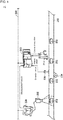
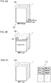
- Fig. 1 is a schematic diagram showing the configuration of a system to be simulated by the simulator according to the present embodiment.
- a conveyor tracking system 1 includes a robot 210, which picks up a workpiece 232 transported continuously on a conveyor 230, and transfers to and places the workpiece 232 at a predetermined position.
- the robot 210 is one example of a processing device.
- the workpiece 232 is one example of a target. This series of actions performed by the robot 210, or picking, transferring, and placing, may be referred to as the pick-and-place operation.
- the conveyer is an example of a carrier
- the workpiece is an example of a target
- the robot is an example of a processing device that processes the target.
- the target and the processing device may not be limited to these examples, and may be selected as appropriate in accordance with the system to be simulated.
- an imaging unit 222 captures an image of an imaging area defined on a part of the conveyor 230, and a visual sensor 220 performs image measurement including pattern matching of the image data captured by the imaging unit 222 and obtains the measurement results including information about the position, orientation, and other parameters of the workpiece 232.
- a controller 200 executes a predetermined control logic based on the measurement results obtained by the visual sensor 220 to generate a control instruction for the robot 210.
- the controller 200 refers to the status value of the robot 210, and an encoder value provided from an encoder 236, which is connected to a drive roller 234 for driving the conveyor 230.
- the controller 200 and the visual sensor 220 are connected to each other with a network 202 to allow data communication between them.
- the measurement results are transmitted from the visual sensor 220 to the controller 200 through the network 202.
- the controller 200 typically includes a programmable logic controller (PLC).
- PLC programmable logic controller
- the conveyor tracking system 1 shown in Fig. 1 may examine its processing capability by increasing the moving speed of the conveyor 230 and including an additional robot 210.
- Fig. 2 is a schematic diagram showing the configuration of a conveyor tracking system 2 including a robot 210 added to the configuration of the conveyor tracking system 1 shown in Fig. 1 .
- a robot 210 added to the configuration of the conveyor tracking system 1 shown in Fig. 1 .
- actually adding the robot 210 to the system as shown in Fig. 2 and checking its processing capability may be intended, actually installing the system is often difficult due to the cost or time constraints.
- the simulator is to be designed to achieve simpler estimation of changes in the system caused by such an additional device as shown in Fig. 2 .
- the simulator virtually creates a system to be simulated in a three-dimensional virtual space, and combines the virtually created system with actually captured image data to achieve more efficient simulation.
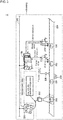
- Fig. 3 is a schematic diagram describing a simulation method implemented by the simulator according to the present embodiment.
- the simulator models the entire conveyor tracking system 2, which is to be simulated, and incorporates image data representing an image captured by the imaging unit 222 into this system model. In other words, the simulator uses the actually captured image data in the model of the conveyor tracking system 1.
- the simulator with this structure simulates the performance of any manufacturing system while incorporating the state of the actual manufacturing system.
- the actually captured image data may not be the data captured in the conveyor tracking system 1 shown in Figs. 1 and 2 that has yet to be improved, and may be data representing any image captured by any system or under any situation.
- the image data may be any data including chronological change information about a target to be simulated (typically, a workpiece 232).
- the Image data may be moving image data or data representing a plurality of still images arranged chronologically.
- the reproduction speed of the moving image data or the update frequency of the data representing the still images can be adjusted as appropriate to adjust the chronological changes (or the moving speed) of a workpiece to be controlled. Adjusting the image data incorporated in the system model in this manner allows the simulation to yield an optimal value for the chronological changes of the control target.
- still images that are not captured sequentially but are captured in different situations may be arranged as chronologically changing images and used as moving image data. Although the images generated in this case have no overlapping between them, this causes substantially no problem in performing the simulation.
- the structure including the visual sensor 220 and the controller 200 connected to each other with a network as shown in Figs. 1 to 3 can have a delay (time lag) between the timing when image measurement is performed by the visual sensor 220 and the timing when the results from the image measurement reach the controller 200.
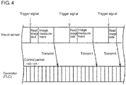
- Fig. 4 is a schematic diagram showing a procedure performed in the system including a visual sensor and a controller.
- the visual sensor 220 reads image data in response to a trigger signal from an external unit, and performs image measurement of the read image data.
- the measurement results from the image measurement are transmitted to the controller 200.
- the delay time may not be negligible.
- a delay time that is not negligible would prevent the robot from correctly performing its pick-and-place operation.
- the simulator 100 corrects an error caused by that delay time and executes a control logic for controlling the robot.
- the hardware configuration of the simulator 100 according to the present embodiment will now be described.
- the simulator 100 according to the embodiment is implemented typically by one or more computers executing a program.
- Fig. 5 is a schematic diagram showing the hardware configuration of the simulator 100 according to the present embodiment.
- the simulator 100 is, for example, a computer having the general-purpose computer architecture.
- the simulator 100 includes a processor 102, a main memory 104, an input unit 106, a display unit 108, a network interface 110, a hard disk drive (HDD) 120, an optical drive 112, and a communication interface 116. These components are connected to each other with an internal bus 118 in a communicable manner.
- the processor 102 loads a program stored in the hard disk drive 120 into the main memory 104 and executes the program to implement the functions and the processing described later.
- the main memory 104 is a volatile memory and functions as a working memory used for program execution by the processor 102.
- the input unit 106 typically includes a keyboard, a mouse, a touch panel, and a touchpad, and receives a user operation.
- the display unit 108 includes a display and an indicator, and presents various pieces of information to a user.
- the network interface 110 exchanges data with external devices such as a server through a network.
- the optical drive 112 reads various programs from an optical disc 114 or other media, and installs the programs into the hard disk drive 120.
- the communication interface 116 is, for example, a universal serial bus (USB) communication interface, and exchanges data with external devices such as an auxiliary storage through local communications.
- USB universal serial bus
- the hard disk drive 120 stores an operating system (OS) 122, a program for providing the functions of the simulator, such as a simulation program 124, and also stores a preliminarily obtained image data group 140 used for simulation.
- OS operating system
- simulation program 124 a program for providing the functions of the simulator, such as a simulation program 124, and also stores a preliminarily obtained image data group 140 used for simulation.
- a program may be downloaded from a server or other devices on the network.
- an OS may be installed on the computer to provide the basic function of the computer, in addition to a program for providing the functions according to the present embodiment.
- the simulation program according to the present embodiment may call program modules included in the OS in a predetermined order and/or at predetermined timings as appropriate to perform processing. More specifically, the program according to the present embodiment may not include these program modules and may cooperate with the OS to perform processing. The program according to the present embodiment may not include such modules.
- the program according to the present embodiment may be incorporated as a part of another program to be combined.
- the program according to the present embodiment may not thus include modules of the program to be combined, and may cooperate with the program to achieve processing.
- the simulation program according to the present embodiment may be incorporated in the other program.
- Fig. 5 shows the simulator 100 that is a general-purpose computer
- the simulator 100 may be partly or entirely implemented using a dedicated circuit (e.g., an application specific integrated circuit, or ASIC). Additionally, an external device may perform a part of the processing of the simulator 100.
- a dedicated circuit e.g., an application specific integrated circuit, or ASIC.
- an external device may perform a part of the processing of the simulator 100.
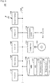
- Fig. 6 is a schematic diagram showing the functional structure of the simulator 100 according to the present embodiment.
- the simulator 100 shown in Fig. 6 includes a visual sensor simulator 150 (measurement unit), a controller simulator 160 (execution unit), a reproduction module 170 (reproduction unit), a user interface module 180, and an encoder emulator 190 as software functions. This group of functional modules is typically implemented by the processor 102 executing the simulation program 124 (refer to Fig. 5 ).
- the simulator 100 further includes a storage unit 154.
- the storage unit 154 is a storage area in the hard disk drive 120 included in the simulator 100.
- the user interface module 180 provides an operation screen for aiding the user to set and generate a setting parameter 152, a control program 162, and three-dimensional design data 172.
- the user interface module 180 also provides any user interface used when the reproduction module 170 displays simulation results.
- the user interface module 180 includes a model creating module 182 (creating unit) for handling the three-dimensional design data 172.
- the model creating module 182 virtually creates the system to be simulated in a three-dimensional virtual space. More specifically, the model creating module 182 displays a three-dimensional virtual space, and provides a setting and operation screen for creating the system to be simulated in the three-dimensional virtual space.
- the simulator 100 typically creates a system including a carrier (typically, a conveyor) virtually in a three-dimensional virtual space.
- the system model includes the visual sensor 220 virtually located at a first position on a transporting path associated with the carrier (conveyor), and the controller 200 virtually located at a second position on the transporting path.
- the visual sensor simulator 150 is a module for simulating the processing performed by the visual sensor 220, and performs various image measurements of preliminarily obtained image data. More specifically, in response to a read instruction (typically, a trigger signal) from the controller simulator 160, the visual sensor simulator 150 reads the corresponding image data from the preliminarily obtained image data group 140, and performs the image measurement corresponding to the processing performed by the visual sensor 220 (refer to Figs. 1 to 3 ). The measurement results from the image measurement performed by the visual sensor simulator 150 are output to the controller simulator 160. The output processing corresponds to the transmission of the measurement results obtained by the visual sensor 220 to the controller 200 through the network 202 in the conveyor tracking system shown in Figs. 1 to 3 . The image measurement in the visual sensor simulator 150 is performed in accordance with a predetermined setting parameter 152.
- a read instruction typically, a trigger signal
- the controller simulator 160 executes a control operation for generating a control instruction for a robot, which is an example of the processing device, based on the measurement results from the visual sensor simulator 150.
- the controller simulator 160 is a module for simulating the processing in the controller 200 (refer to Figs. 1 to 3 ), and executes a control operation (a sequence instruction, a motion instruction, or various functional instructions) in accordance with the preliminarily created control program 162. Trace data including input and output associated with the control operation executed in the controller simulator 160 is output to the reproduction module 170 as time-series data.
- the control operation executed in the controller simulator 160 includes processing for generating a read instruction (trigger signal) for reading image data, which is to be transmitted to the visual sensor simulator 150. More specifically, when a predetermined condition is satisfied, the controller simulator 160 generates a trigger signal.
- the predetermined condition is, for example, that the conveyor has moved by a predetermined distance, or a predetermined period has ended. As described later, the distance by which the conveyor has moved is determined based on information generated by the encoder emulator 190. The information generated by the encoder emulator 190 is also provided from the controller simulator 160 to the visual sensor simulator 150.
- the reproduction module 170 reproduces the behavior of the created system based on time-series data (trace data) for a control operation output from the controller simulator 160. More specifically, the reproduction module 170 uses the three-dimensional design data 172, which is a definition file, to visualize the system virtually created in the three-dimensional virtual space, and also uses the trace data provided from the controller simulator 160 to reproduce the chronological changes of the workpiece or the robot in the system. In this manner, the reproduction module 170 represents the chronological changes of the simulation results in the form of animation or a moving image on the display unit 108 of the simulator 100 ( Fig. 5 ).
- the reproduction module 170 may incorporate image data stored in the storage unit 154 and information associated with the image data in reproducing the simulation results. For example, the reproduction module 170 may correct the display position of a target (workpiece) based on information indicating the position or the displacement of the carrier (conveyor) provided together with the measurement results.
- Fig. 6 show the example in which the reproduction module 170 reproduces the behavior of the created system using the trace data output from the controller simulator 160
- the simulator 100 may not include the reproduction module 170.
- the trace data from the controller simulator 160 may be output to an external device or an external application, and the external device or the external application may reproduce the behavior of the system.
- the reproduction module 170 may simply generate and store moving image data for reproducing the behavior of the system in any storage medium, which may then be reproduced by another application.
- the encoder emulator 190 generates information indicating the position or displacement of the carrier in a manner associated with the movement of the carrier.
- the encoder emulator 190 may output the encoder value indicating a displacement from a reference position, or may generate pulses proportional to a movement of the carrier (conveyor) per unit time.
- the encoder value indicates the position of the conveyor, and the number of pulses per unit time indicates the speed of the conveyor.
- the storage unit 154 stores image data read in response to a read instruction (trigger signal) in a manner associated with information indicating the position or the displacement of the carrier (conveyor) serving as a reference for the image measurement performed in response to the read instruction.
- a read instruction trigger signal
- the reference for the image measurement may be the encoder value at the timing when the trigger signal is input into the visual sensor simulator 150, or may be the encoder value at the timing when the visual sensor simulator 150 reads the image data.
- the read image data is associated with the information serving as the reference of the image measurement and then is stored into the storage unit 154.
- the image data that has undergone the image measurement is associated with such additional information as described above. This allows correction of a delay time that is not negligible in the control simulator 160 when that delay time occurs before the processing using the measurement results from the image measurement is started.
- Fig. 7 is a flowchart showing the procedure of simulation performed by the simulator 100 according to the present embodiment.
- the simulator 100 first receives the settings of the system model (step S2).
- the settings of the system model include the arrangement of the devices included in the system, and the moving speed of the conveyor, which is a carrier. Based on these system model settings, the simulator 100 (model creating module 182) virtually creates a system to be simulated in a three-dimensional virtual space.
- the simulator 100 receives an imaging area for a visual sensor defined in the system model (step S4). Based on the relative positional relationship between the created system and the defined imaging area, the simulator calculates a calibration parameter, which is a transform parameter for transforming the measurement results into an input value for a control operation.
- the visual sensor simulator 150 may calculate the calibration parameter.
- the simulator 100 (user interface module 180) then receives a control program for controlling the system model (step S6).
- the control program is associated with the system, and is to be executed by the controller simulator 160.
- the simulator 100 receives the settings for image measurement to be performed by the visual sensor simulator 150 (step S8).
- the simulator 100 When instructed to start the simulation, the simulator 100 (encoder emulator 190) updates an encoder value indicating the position or displacement of a virtual conveyor at specified time intervals (step S10).
- the simulator 100 determines whether a condition for generating a trigger signal is satisfied (step S12). When the condition is satisfied (Yes in step S12), the simulator 100 virtually generates a trigger signal (step S14). When the condition is not satisfied (No in step S12), the processing in step S14 is skipped.
- the simulator 100 In response to the generated trigger signal, the simulator 100 (visual sensor simulator 150) reads the corresponding image data from the preliminarily obtained image data group (step S100), and performs the image measurement (step S102). After the image measurement, the simulator 100 (visual sensor simulator 150) outputs the measurement results (step S104), and associates the read image data with the encoder value provided from the encoder emulator 190 when the image data is read, and stores the read image data (step S106). The processing in steps S100 to S106 is performed independently of the processing performed in the controller simulator 160.
- the simulator 100 determines whether the measurement results from the image measurement have been updated (step S16). More specifically, the simulator 100 determines whether new measurement results have been received from the visual sensor simulator 150. When the measurement results have been updated (Yes in step S16), the simulator 100 (controller simulator 160) executes a control operation based on the updated measurement results (step S18). When the measurement results have not been updated (No in step S16), the processing in step S18 is skipped.
- the simulator 100 (controller simulator 160) stores values calculated through the control operation in a manner associated with the corresponding chronological information (step S20).
- the simulator 100 stores trace data, which is an example of time-series data.
- the simulator 100 determines whether a preset simulation period has ended (step S22). When the simulation period has not ended (No in step S22), the processing in step S10 and subsequent steps is repeated.
- the simulator 100 reproduces the behavior of the system model using the trace data sequentially stored in step S20 (step S24).
- the simulator 100 can change the time intervals and the update frequency of the behavior of the reproduced system model as appropriate in accordance with a user operation.
- a tact time or other performance of the system model can be evaluated.
- Fig. 8 is a schematic diagram describing information serving as a reference used for image measurement performed by the simulator 100 according to the present embodiment.
- the visual sensor simulator 150 reads image data in response to a trigger signal internally generated by the controller simulator 160, and performs image measurement of the read image data.
- the trigger signal is generated at time T1, and the visual sensor simulator 150 then starts reading the image data.
- the visual sensor simulator 150 completes its image data reading, and starts the image measurement at time T2.
- the information indicating the carrier (conveyor) position or displacement serving as a reference for the image measurement may be an encoder value at the input of the trigger signal into the visual sensor simulator 150 (at time T1) (an encoder value E3 in the example shown in Fig. 8 ).
- the information may be an encoder value at the start of the image measurement (at time T2) after the image data reading completes (an encoder value E4 in the example shown in Fig. 8 ).
- the information may be the average value of the encoder values output during the image data reading. For example, when image data is read between times T1 and T2, the average value of the encoder value E3 at time T1 and the encoder value E4 at time T2 ((E3 + E4)/2) may be used.
- the reference information described with reference to Fig. 8 is one example, and may be any information that can be used to determine the position or the timing at which image data corresponding to the measurement results has been captured after the image data undergoes the image measurement.
- the processing for storing image data into the storage unit 154 ( Fig. 6 ) in the simulator 100 will now be described.
- the simulator 100 stores the image data read in response to an internally generated trigger signal (read instruction) in a manner associated with the information indicating the conveyor (carrier) position or displacement serving as a reference for the image measurement performed in response to the read instruction.
- the image data may be associated with the information indicating the conveyor (carrier) position or displacement serving as a reference for the image measurement with any method that allows the information to be used later. A few typical methods will now be described.
- Figs. 9A to 9C are diagrams each describing a method for storing image data used by the simulator 100 according to the present embodiment.
- an encoder value is a typical example of the information indicating the conveyor (carrier) position or displacement serving as a reference used for the image measurement in the present embodiment, any other value may be used as such information.
- Fig. 9A shows an example in which an encoder value is used as a file name 157 of image data 156 to be stored or as a part of the file name 157.
- the file name 0001200.jpg includes a main part 0001200, which corresponds to an encoder value.
- the main part of the file name 157 can be extracted to determine the encoder value 0001200 serving as a reference in the image measurement of the image data 156. In this manner, the encoder value may be used in the file name of image data.
- Fig. 9B shows an example in which an encoder value is used as the file name of image data to be stored or as a part of the file name.
- the Exif area 158 may have various pieces of information.
- the Exif area 158 may include an encoder value serving as a reference used for image measurement.
- the information included in the Exif area 158 can be extracted to determine the encoder value that has served as the reference in the image measurement of the image data 156. In this manner, encoder value information may be added in a predetermined area of image data.
- Fig. 9C shows an example in which a correspondence table 159 is provided in addition to one or more pieces of image data 156.
- the table includes information associated with each piece of image data 156.
- each file name of the stored image data 156 is associated with the corresponding encoder value.
- the correspondence table 159 can be used to easily determine the encoder value that has served as the reference in the image measurement of the image data to be stored.
- a process for creating the model of the system to be simulated will now be described.
- the process for creating the system model is typically performed by the model construction module 182 ( Fig. 6 ). This process corresponds to the reception of the setting of the system model shown in Fig. 7 described above (step S2).
- a user may directly create the system model to be simulated on an edit screen provided by the simulator 100, or may load preliminary generated design data (computer aided design (CAD) data) into the simulator to create the system model.
- preliminary generated design data computer aided design (CAD) data
- the user may edit the past data to create the system model.
- the simulator 100 may use any method to create the model system.
- Fig. 10 is a diagram showing an example user interface screen for the system model provided by the simulator 100 according to the present embodiment.
- Fig. 10 shows a system model that performs a simple pick-and-place operation.
- the user interface screen shown in Fig. 10 shows two conveyors 301 and 302 arranged parallel to each other in a three-dimensional virtual space 300.
- Two robots 311 and 313 are arranged in correspondence with predetermined positions on the conveyor 302.
- This system model is used for an application in which workpieces are transported by the conveyor 301 from left to right in the drawing, and the robots 311 and 313 each pick up a target workpiece and place the workpiece on the conveyor 302.
- an object in the three-dimensional virtual space 300 can be rendered in any direction. More specifically, a user can freely change a point of view for rendering in the user interface screen.
- Fig. 11 is a schematic diagram describing the coordinate systems defined in the three-dimensional virtual space provided by the simulator 100 according to the present embodiment.
- the three-dimensional virtual space 300 includes X, Y, and Z axes defining a world coordinate system 320.
- the world coordinate system 320 serves as a reference coordinate system for defining the positions of components of the system model.
- the controller uses a conveyor coordinate system 303 that includes the initial position of each of the conveyors 301 and 302 as the origin.
- the conveyor coordinate system 303 is a coordinate system defined for a conveyor included in the system model.
- the conveyor coordinate system 303 includes three axes in three directions, which are the transport direction of the conveyors 301 and 302, the direction orthogonal to the transport direction, and the direction orthogonal to the transporting surfaces of the conveyors 301 and 302.
- the robots 311 and 313 may have robot coordinate systems 312 and 314, which are defined independently of each other for controlling the corresponding robots.
- the robot coordinate systems 312 and 314 are defined for the robots 311 and 313 in the system model, and have the installation positions of the robots 311 and 313 as their origins.
- the robot coordinate systems 312 and 314 are used to control the behavior of the robots 311 and 313 as viewed from a robot controller.
- tool coordinate systems having the ends of the robots 311 and 313 as their origins may further be defined.
- the simulator 100 preliminarily calculates calibration parameters for transforming coordinates in one coordinate system to coordinates in another coordinate system, among the multiple coordinate systems shown in Fig. 11 .
- calibration parameters include coefficients A to F for transforming the coordinates (x, y) in the camera coordinate system into the coordinates (X, Y) in the robot coordinate system.
- the transporting operation of a carrier is to be reproduced in the three-dimensional virtual space, and thus parameters for the transporting operation are also calculated.
- the simulator 100 calculates a transform coefficient used for transforming a unit movement of the workpiece transporting carrier (conveyor) in the created system into the moving speed of the target (workpiece) in the created system.
- the transform coefficient includes displacements of the workpiece in X-direction and Y-direction per unit movement of the conveyor (typically, per pulse from the encoder). For example, when an encoder generates one pulse per rotation, the integrated value of pulses from the encoder is calculated as the encoder value. In other words, one pulse is equivalent to an increment of 1 in the encoder value.
- Such movements are used to calculate the chronological changes of a workpiece when the behavior of the created system is reproduced.
- the transform coefficient is calculated based on the tilting of the conveyor with respect to the robot coordinate system.
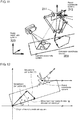
- Fig. 12 is a schematic diagram describing the procedure for calculating the movement per pulse in the simulator 100 according to the present embodiment.
- the conveyor and the robot are rotated about the Z axis of the world coordinate system.
- the movement per pulse is calculated in the manner described below.
- 1 is the movement per pulse in the moving direction of the conveyor.
- Movement X in X ⁇ direction per pulse 1 ⁇ cos ⁇ ⁇ ⁇
- Movement Y in Y ⁇ direction per pulse 1 ⁇ sin ⁇ ⁇ ⁇ ⁇
- the movement per pulse may be calculated by applying ( ⁇ - ⁇ ) to the movement per pulse in the moving direction of the conveyor.
- Fig. 12 shows the example in which the conveyor and the robot are rotated about the Z axis of the world coordinate system for ease of explanation.
- the conveyer and the robot may be rotated about the X axis and the Y axis in addition to the Z axis. The calculation described below thus reflects the rotation angle for each axis.
- the conveyor is tilted by a rotation angle Ox about the X axis, by a rotation angle ⁇ y about the Y axis, and by a rotation angle ⁇ z about the Z axis of the world coordinate system.
- the robot is tilted by a rotation angle ⁇ x about the X axis, by a rotation angle ⁇ y about the Y axis, and by a rotation angle ⁇ z about the Z axis of the world coordinate system.
- a unit matrix of 3 ⁇ 3 is rotated about the X axis by an angle ( ⁇ y - ⁇ y), by an angle ( ⁇ x - ⁇ x) about the Y axis, and by an angle ( ⁇ z - ⁇ z) about the Z axis. This generates a rotation matrix.
- the movement 1 per pulse in the moving direction of the conveyor may be obtained from the initial setting value.
- the coordinates X and Y calculated by multiplying the rotation matrix and the local coordinate axis (1, 0, 0) of the system model correspond to the movement (X) in X-direction per pulse and the movement (Y) in Y-direction per pulse as described below.
- the values indicating the movement are in millimeters.
- Movement x y z rotation matrix ⁇ 1 0 0
- Movement X in X ⁇ direction per pulse movement x mm / pulse
- Movement Y in Y ⁇ direction per pulse movement y mm / pulse
- the movement (X) in X-direction per pulse and the movement (Y) in Y-direction per pulse, which are yielded from the above calculation process, are calculated as transform coefficients.
- Fig. 13 is a diagram describing the measurement results obtained by the visual sensor simulator 150 included in the simulator 100 according to the present embodiment.
- the visual sensor simulator 150 which simulates the visual sensor 220, performs image measurement of image data including a plurality of pixels, and thus yields measurement results defined using the pixel values.
- Fig. 13 shows the results of pattern matching with any pre-registered image patterns.
- the image data includes two objects matching pre-registered image patterns.
- the output measurement results are the values (x1, y1, ⁇ 1) and (x2, y2, ⁇ 2).
- the measurement results include the positions of objects matching the pre-registered image patterns (both defined by pixel values), and the rotation angles (attitude) with respect to the pre-registered image patterns.
- the coordinates in the camera coordinate system are transformed into the coordinates in the world coordinate system or the conveyor coordinate system using the calibration parameters (coefficients A to F).
- the measurement results (including the detected workpiece position) output from the visual sensor simulator 150 are transformed into the coordinates in the robot coordinate system, and input into the controller simulator 160.
- the coordinates in the robot coordinate system are transformed into the corresponding coordinates in the world coordinate system in the three-dimensional virtual space 300, in which the system model is defined.
- Parameters for transforming the coordinates in the robot coordinate system into the coordinates in the world coordinate system can be calculated in the same manner as described above, or with the same procedure as the procedure for calculating parameters for transforming the coordinates in the camera coordinate system into the coordinates in the robot coordinate system.
- the simulator 100 can use coefficients A1 to F1 for transforming the coordinates (x, y) in the camera coordinate system into the coordinates (X, Y) in the world coordinate system.
- the simulator 100 can thus calculate the initial display position of the workpiece at the input into the controller simulator 160 based on the coordinates (x, y) of the workpiece detected by the visual sensor simulator 150 in the manner described below.
- Workpiece initial display position X A 1 ⁇ x + B 1 ⁇ y + C 1
- Workpiece initial display position Y D 1 ⁇ x + E 1 ⁇ y + F 1
- the display position of each workpiece is sequentially updated in accordance with changes in the encoder value.
- the display position is updated in this manner to reproduce the workpiece that is being transported on the conveyor.
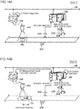
- Figs. 14A and 14B are schematic diagrams each describing a positional deviation of a target in the conveyor tracking system shown in Figs. 1 to 3 .
- Fig. 14A shows the system in which the workpiece 232 is captured by the imaging unit 222, and the image data is read.
- the process shown in Fig. 14A corresponds to the simulation in which the visual sensor simulator 150 in the simulator 100 reads image data.
- the visual sensor 220 reads image data from the imaging unit 222, performs image measurement, and transmits the measurement results to the controller 200.
- the process shown in Fig. 14B corresponds to the simulation in which the controller simulator 160 receives the measurement results from the visual sensor simulator 150 and executes a predetermined control operation based on the measurement results.
- the visual sensor 220 uses some time to read image data, perform image measurement, and transmit the measurement results to the controller 200. For an image of a target (workpiece 232) captured by the imaging unit 222 at time T1, the controller 200 will start a control operation at time T2 for the image data based on the image measurement results.
- the workpiece 232 moves by a distance corresponding to the delay time.
- the distance moved by the workpiece 232 between time T1 and time T2 is to be corrected.
- the distance to be corrected by the visual sensor simulator 150 will also be referred to as a correction distance.
- time T1 corresponds to a reference for the image measurement performed in response to a read instruction (trigger signal).
- the visual sensor simulator 150 outputs, to the controller simulator 160, an encoder value indicating the reference used in the image measurement to generate the measurement results in addition to the measurement results. More specifically, the visual sensor simulator 150 outputs, to the controller simulator 160, the measurement results together with the information indicating the conveyor (carrier) position or displacement associated with the image data used to obtain the measurement results.
- the controller simulator 160 calculates the distance moved by the workpiece from the reference timing in the image measurement based on the difference between the current encoder value and the encoder value provided together with the measurement results. More specifically, the controller simulator 160 executes the control operation using the position of the workpiece (target) in the three-dimensional virtual space corrected based on the information indicating the conveyor (carrier) position or displacement provided together with the measurement results.
- the controller simulator 160 subtracts the encoder value Et provided together with the measurement results from the encoder value Ec at the start of the control operation or during execution of an instruction in the control operation.
- the controller simulator 160 calculates the amount of correction in X-direction and the amount of correction in Y-direction assuming that the conveyor coordinate system is tilted with respect to the world coordinate system (sharing the same Z-axis).
- the correction distance is equal to the movement along any particular axis.
- the controller simulator 160 calculates the correction distance (amount of correction) for the position of the target based on the difference between the encoder value provided together with the measurement results (information indicating the position or the displacement of the carrier) and the encoder value during the control operation (information indicating the current position or displacement of the carrier).
- the controller simulator 160 corrects the position of the workpiece at each timing using the correction distance, and generates a control instruction for the robot.
- the process for displaying the simulation results will now be described.
- the process for displaying the simulation results, or the process for reproducing the behavior of the system model, is typically performed by the reproduction module 170 ( Fig. 6 ). This process corresponds to the reproduction of the behavior of the system model (step S24) shown in Fig. 7 described above.
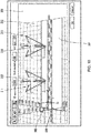
- Fig. 15 is a diagram showing an example user interface screen for reproducing the behavior of the system provided by the simulator 100 according to the present embodiment.
- the behavior of the created system is reproduced based on the results of a control operation executed using the measurement results input from the visual sensor simulator 150. More specifically, the positions and the attitudes of the robots 311 and 313 are updated sequentially based on a control instruction obtained through the control operation executed in the controller simulator 160. This enables observation of the movement of the robots 311 and 313.
- the user interface screen also displays the workpiece 350 in the created system model based on the information about the workpiece recognized by the visual sensor simulator 150.
- the workpiece 350 appears to move in response to the movement of the conveyors 301 and 303.
- the position of the workpiece 350 changes in accordance with the pick-and-place operation performed by each of the robots 311 and 313.
- the reproduction module 170 may then display, in the system, each workpiece recognized in the visual sensor simulator 150, and may update the position of the workpiece over time.
- Tracking and displaying the workpiece 350 in this manner allows the user to easily recognize the behavior of the created system.
- the user interface screen also displays measurement results 360 including the input image used for the image measurement performed by the visual sensor simulator 150.
- the measurement results 360 appear when the behavior of the system is reproduced.
- the reproduction module 170 displays the behavior of the created system together with the image data that has undergone the image measurement.
- the measurement results from the visual sensor simulator 150 may also be output together with the image data used to obtain the measurement results. In this case, the measurement results may be superimposed on the image data, or the input image data and the measurement results may appear side by side.
- an object included in a three-dimensional virtual space can be rendered in any direction. More specifically, a user can freely change a point of view for rendering in the user interface screen. The user can also freely set the duration of the reproduction time and the reproduction speed.
- the simulation results may be displayed after the display position of the workpiece is corrected as appropriate.
- trace data output from the controller simulator 160 includes information indicating the position of the workpiece corrected using the correction distance described above
- the position information can be directly used for displaying the simulation results.
- the initial display position of the workpiece or other information may be corrected in the same manner as described above for the calculation of the correction distance.
- the simulation results may then be reproduced based on the corrected information.
- the reproduction module 170 corrects the display position of the target (workpiece) based on the information indicating the position or displacement of the carrier (conveyor) provided together with the measurement results.
- the reproduction module 170 typically updates the display position of each component in the created system in a manner associated with the encoder value from the encoder 236.
- the display position of the workpiece is corrected based on the difference between the target encoder value and the encoder value provided together with the image data used for the image recognition.
- the correction process described above allows the workpiece to appear at a more accurate position when the simulation results are reproduced. Further, the timing for image measurement is simulated more precisely.
- the encoder emulator 190 and the controller simulator 160 may be an integrated single unit. More specifically, the program causing the control operation executed by the controller simulator 160 may include the processing for updating an encoder value. In another modification, the controller simulator 160 may execute the control program 162 in parallel with the program for implementing the encoder emulator 190.
- the function of the encoder emulator 190 may be implemented by an external device or a real encoder.
- the encoder 236 shown in Figs. 1 to 3 which detects the operation of the carrier (conveyor 230) independent of the controller 200 and the visual sensor 220, may not be directly associated with the operations of the controller 200 and the visual sensor 220, and may thus be implemented in any form.
- the simulator 100 allows more efficient simulation using preliminary obtained image data for a target such as a workpiece. Further, the timing for image measurement of such preliminary obtained image data is simulated more precisely.
Landscapes
- Engineering & Computer Science (AREA)
- Physics & Mathematics (AREA)
- General Physics & Mathematics (AREA)
- Manufacturing & Machinery (AREA)
- Quality & Reliability (AREA)
- Computer Vision & Pattern Recognition (AREA)
- Theoretical Computer Science (AREA)
- Automation & Control Theory (AREA)
- General Engineering & Computer Science (AREA)
- Robotics (AREA)
- Mechanical Engineering (AREA)
- General Health & Medical Sciences (AREA)
- Health & Medical Sciences (AREA)
- Psychiatry (AREA)
- Social Psychology (AREA)
- Human Computer Interaction (AREA)
- Multimedia (AREA)
- Manipulator (AREA)
- Testing And Monitoring For Control Systems (AREA)
- Debugging And Monitoring (AREA)
- Image Processing (AREA)
- Feedback Control In General (AREA)
- Image Analysis (AREA)
- Length Measuring Devices By Optical Means (AREA)
Description
- The present invention relates to a simulator, a simulation method, and a simulation program for estimating the behavior of a system.
- In the field of factory automation (FA), automatic control techniques using visual sensors are used widely. Such techniques include automatic processing in which an image of a target such as a workpiece is captured, the captured image undergoes image measurement such as pattern matching, and various control devices operate based on the measurement results.
- For example, Japanese Unexamined Patent Application Publication No.
2012-187651 - Designing or examining the system to be controlled with the above automatic control technique may need preliminary evaluation of the performance of the entire system. In response to this, a technique has been developed for virtually creating a system and simulating its operation. For example, Japanese Unexamined Patent Application Publication No.
2013-191128 Patent Literature 2, a 3D simulator and a visual sensor simulator cooperate with each other to virtually generate captured images of a workpiece in a 3D space at predetermined timings. -
- Patent Literature 1: Japanese Unexamined Patent Application Publication No.
2012-187651 - Patent Literature 2: Japanese Unexamined Patent Application Publication No.
2013-191128 - The technique described in
Patent Literature 2 further involves predefining of workpieces or targets. When, for example, the existing system is to be improved or when the existing system is to be replaced with another system, workpieces are also to be modeled. - A structure for more efficient simulation of a system using preliminary obtained image data for a target such as a workpiece is to be developed. Further, the timing for image measurement of the image data is also to be simulated more precisely.
- A simulator according to one aspect of the present invention estimates a behavior of a system. The simulator includes a creating unit that virtually creates a system including a carrier in a three-dimensional virtual space. The created system includes a visual sensor virtually located at a first position on a transporting path associated with the carrier, and a processing device virtually located at a second position on the transporting path. The simulator includes a measurement unit, an execution unit, a storage unit, and a reproduction unit. The measurement unit performs image measurement of preliminarily obtained image data corresponding to processing performed using the visual sensor. The execution unit executes a control operation for generating a control instruction directed to the processing device based on a measurement result obtained by the measurement unit and for generating a read instruction directed to the measurement unit for reading the image data. The storage unit stores the image data read in response to the read instruction in a manner associated with information indicating a position or a displacement of the carrier. The position or the displacement serves as a reference for the image measurement performed in response to the read instruction. The reproduction unit reproduces a behavior of the created system based on time-series data for the control operation output from the execution unit and the information associated with the image data stored in the storage unit. The reproduction herein refers to a computation performed by the simulator for creating the system in the virtual space and causing the system to operate virtually. The reproduction includes simulation.
- In some embodiments, the measurement unit outputs, to the execution unit, the measurement result together with the information indicating the position or the displacement of the carrier associated with the image data used to generate the measurement result.
- In some embodiments, the execution unit executes the control operation using a position of a target in the three-dimensional virtual space corrected based on the information indicating the position or the displacement of the carrier provided together with the measurement result.
- In some embodiments, the execution unit calculates an amount of correction for the position of the target based on a difference between the information indicating the position or the displacement of the carrier provided together with the measurement result and information indicating the position or the displacement of the carrier during execution of the control operation.
- In some embodiments, the reproduction unit displays the behavior of the created system and the image data that has undergone the image measurement.
- In some embodiments, the reproduction unit corrects a display position of the target based on the information indicating the position or the displacement of the carrier provided together with the measurement result.
- In some embodiments, the simulator further includes a generating unit that generates information indicating the position or the displacement of the carrier in a manner associated with movement of the carrier.
- In some embodiments, the storage unit associates the information with a file name of the image data or an area included in the image data.
- A simulation method according to another aspect of the present invention is implemented by a computer to estimate a behavior of a system. The simulation method includes virtually creating a system including a carrier in a three-dimensional virtual space. The created system includes a visual sensor virtually located at a first position on a transporting path associated with the carrier, and a processing device virtually located at a second position on the transporting path. The method includes performing image measurement of preliminarily obtained image data corresponding to processing performed using the visual sensor, executing a control operation for generating a control instruction directed to the processing device based on a measurement result obtained from the image measurement and for generating a read instruction for reading the image data to start the image measurement, storing the image data read in response to the read instruction in a manner associated with information indicating a position or a displacement of the carrier serving as a reference for the image measurement performed in response to the read instruction, and reproducing a behavior of the created system based on time-series data for the control operation output as a result of the executing process and information associated with the stored image data.
- A simulation program according to another aspect of the present invention is used to estimate a behavior of a system. The simulation program causes a computer to implement virtually creating a system including a carrier in a three-dimensional virtual space. The created system includes a visual sensor virtually located at a first position on a transporting path associated with the carrier, and a processing device virtually located at a second position on the transporting path. The program causes the computer to implement performing image measurement of preliminarily obtained image data corresponding to processing performed using the visual sensor, executing a control operation for generating a control instruction directed to the processing device based on a measurement result obtained from the image measurement and for generating a read instruction for reading the image data to start the image measurement, storing the image data read in response to the read instruction in a manner associated with information indicating a position or a displacement of the carrier serving as a reference for the image measurement performed in response to the read instruction, and reproducing a behavior of the created system based on time-series data for the control operation output as a result of the executing process and information associated with the stored image data.
- Embodiments of the present invention allow more precise simulation of a system using preliminary obtained image data for a target such as a workpiece.
-
-
Fig. 1 is a schematic diagram showing the configuration of a system to be simulated by the simulator according to one embodiment. -
Fig. 2 is a schematic diagram showing the configuration of a manufacturing system including a robot added to the configuration of the manufacturing system shown inFig. 1 . -
Fig. 3 is a schematic diagram describing a simulation method implemented by the simulator according to the embodiment. -
Fig. 4 is a schematic diagram showing a procedure performed in a system including a visual sensor and a controller. -
Fig. 5 is a schematic diagram showing the hardware configuration of the simulator according to the embodiment. -
Fig. 6 is a schematic diagram showing the functional structure of the simulator according to the embodiment. -
Fig. 7 is a flowchart showing the procedure of simulation performed by the simulator according to the embodiment. -
Fig. 8 is a schematic diagram describing information serving as a reference used for image measurement performed by the simulator according to the embodiment. -
Figs. 9A to 9C are diagrams each describing a method for storing image data used by the simulator according to the embodiment. -
Fig. 10 is a diagram showing an example user interface screen for a system model provided by the simulator according to the embodiment. -
Fig. 11 is a schematic diagram describing the coordinate systems defined in the three-dimensional virtual space provided by the simulator according to the embodiment. -
Fig. 12 is a schematic diagram describing the procedure for calculating the movement per pulse in the simulator according to the embodiment. -
Fig. 13 is a diagram describing the measurement results obtained by a visual sensor simulator included in the simulator according to the embodiment. -
Figs. 14A and 14B are schematic diagrams each describing a positional deviation of a target in the conveyor tracking system shown inFigs. 1 to 3 . -
Fig. 15 is a diagram showing an example user interface screen for reproducing the behavior of the system provided by the simulator according to the embodiment. - Embodiments of the present invention will now be described in detail with reference to the drawings. The same or corresponding components in the figures are given the same reference numerals, and will not be described redundantly.
- A simulator according to the present embodiment estimates the behavior of a system. More specifically, the simulator according to the present embodiment estimates the behavior of a virtually created system using image data representing images actually captured by an imaging unit. Although the simulator simulates a conveyor tracking system including one or more devices in the embodiment described below, the simulator may simulate any other system.
- The simulation performed by the simulator according to the present embodiment will now be described briefly.
-
Fig. 1 is a schematic diagram showing the configuration of a system to be simulated by the simulator according to the present embodiment. As shown inFig. 1 , for example, aconveyor tracking system 1 includes arobot 210, which picks up aworkpiece 232 transported continuously on aconveyor 230, and transfers to and places theworkpiece 232 at a predetermined position. Therobot 210 is one example of a processing device. Theworkpiece 232 is one example of a target. This series of actions performed by therobot 210, or picking, transferring, and placing, may be referred to as the pick-and-place operation. - In the embodiment described below, the conveyer is an example of a carrier, the workpiece is an example of a target, and the robot is an example of a processing device that processes the target. The target and the processing device may not be limited to these examples, and may be selected as appropriate in accordance with the system to be simulated.
- To enable the pick-and-place operation of the
robot 210, animaging unit 222 captures an image of an imaging area defined on a part of theconveyor 230, and avisual sensor 220 performs image measurement including pattern matching of the image data captured by theimaging unit 222 and obtains the measurement results including information about the position, orientation, and other parameters of theworkpiece 232. Acontroller 200 executes a predetermined control logic based on the measurement results obtained by thevisual sensor 220 to generate a control instruction for therobot 210. To generate the control instruction for therobot 210, thecontroller 200 refers to the status value of therobot 210, and an encoder value provided from anencoder 236, which is connected to adrive roller 234 for driving theconveyor 230. Thecontroller 200 and thevisual sensor 220 are connected to each other with anetwork 202 to allow data communication between them. The measurement results are transmitted from thevisual sensor 220 to thecontroller 200 through thenetwork 202. Thecontroller 200 typically includes a programmable logic controller (PLC). - The
conveyor tracking system 1 shown inFig. 1 may examine its processing capability by increasing the moving speed of theconveyor 230 and including anadditional robot 210. -
Fig. 2 is a schematic diagram showing the configuration of aconveyor tracking system 2 including arobot 210 added to the configuration of theconveyor tracking system 1 shown inFig. 1 . Although actually adding therobot 210 to the system as shown inFig. 2 and checking its processing capability may be intended, actually installing the system is often difficult due to the cost or time constraints. The simulator is to be designed to achieve simpler estimation of changes in the system caused by such an additional device as shown inFig. 2 . - In response to this, the simulator according to the present embodiment virtually creates a system to be simulated in a three-dimensional virtual space, and combines the virtually created system with actually captured image data to achieve more efficient simulation.
-
Fig. 3 is a schematic diagram describing a simulation method implemented by the simulator according to the present embodiment. With reference toFig. 3 , the simulator models the entireconveyor tracking system 2, which is to be simulated, and incorporates image data representing an image captured by theimaging unit 222 into this system model. In other words, the simulator uses the actually captured image data in the model of theconveyor tracking system 1. - The simulator with this structure simulates the performance of any manufacturing system while incorporating the state of the actual manufacturing system.
- The actually captured image data may not be the data captured in the
conveyor tracking system 1 shown inFigs. 1 and2 that has yet to be improved, and may be data representing any image captured by any system or under any situation. In other words, the image data may be any data including chronological change information about a target to be simulated (typically, a workpiece 232). - The Image data may be moving image data or data representing a plurality of still images arranged chronologically. The reproduction speed of the moving image data or the update frequency of the data representing the still images can be adjusted as appropriate to adjust the chronological changes (or the moving speed) of a workpiece to be controlled. Adjusting the image data incorporated in the system model in this manner allows the simulation to yield an optimal value for the chronological changes of the control target.
- Additionally, still images that are not captured sequentially but are captured in different situations may be arranged as chronologically changing images and used as moving image data. Although the images generated in this case have no overlapping between them, this causes substantially no problem in performing the simulation.
- The structure including the
visual sensor 220 and thecontroller 200 connected to each other with a network as shown inFigs. 1 to 3 can have a delay (time lag) between the timing when image measurement is performed by thevisual sensor 220 and the timing when the results from the image measurement reach thecontroller 200. -
Fig. 4 is a schematic diagram showing a procedure performed in the system including a visual sensor and a controller. Referring now toFig. 4 , for example, thevisual sensor 220 reads image data in response to a trigger signal from an external unit, and performs image measurement of the read image data. The measurement results from the image measurement are transmitted to thecontroller 200. When the total of the time taken for the image measurement and the delay time taken for the transmission shown inFig. 4 is negligible, this can cause no problems. However, as the control period for thevisual sensor 220 is longer, the delay time may not be negligible. - In the conveyor tracking system shown in
Figs. 1 to 3 in which a target (typically, a workpiece 232) moves, a delay time that is not negligible would prevent the robot from correctly performing its pick-and-place operation. - In response to this, the
simulator 100 according to the present embodiment corrects an error caused by that delay time and executes a control logic for controlling the robot. - The hardware configuration of the
simulator 100 according to the present embodiment will now be described. Thesimulator 100 according to the embodiment is implemented typically by one or more computers executing a program. -
Fig. 5 is a schematic diagram showing the hardware configuration of thesimulator 100 according to the present embodiment. With reference toFig. 5 , thesimulator 100 is, for example, a computer having the general-purpose computer architecture. Thesimulator 100 includes aprocessor 102, amain memory 104, aninput unit 106, adisplay unit 108, anetwork interface 110, a hard disk drive (HDD) 120, anoptical drive 112, and acommunication interface 116. These components are connected to each other with aninternal bus 118 in a communicable manner. - The
processor 102 loads a program stored in thehard disk drive 120 into themain memory 104 and executes the program to implement the functions and the processing described later. Themain memory 104 is a volatile memory and functions as a working memory used for program execution by theprocessor 102. - The
input unit 106 typically includes a keyboard, a mouse, a touch panel, and a touchpad, and receives a user operation. Thedisplay unit 108 includes a display and an indicator, and presents various pieces of information to a user. - The
network interface 110 exchanges data with external devices such as a server through a network. Theoptical drive 112 reads various programs from anoptical disc 114 or other media, and installs the programs into thehard disk drive 120. Thecommunication interface 116 is, for example, a universal serial bus (USB) communication interface, and exchanges data with external devices such as an auxiliary storage through local communications. - The
hard disk drive 120 stores an operating system (OS) 122, a program for providing the functions of the simulator, such as asimulation program 124, and also stores a preliminarily obtainedimage data group 140 used for simulation. - Although an intended program is installed in the
simulator 100 via theoptical drive 112 in the configuration example shown inFig. 5 , a program may be downloaded from a server or other devices on the network. - When the simulator is a general-purpose computer as described above, an OS may be installed on the computer to provide the basic function of the computer, in addition to a program for providing the functions according to the present embodiment. In this case, the simulation program according to the present embodiment may call program modules included in the OS in a predetermined order and/or at predetermined timings as appropriate to perform processing. More specifically, the program according to the present embodiment may not include these program modules and may cooperate with the OS to perform processing. The program according to the present embodiment may not include such modules.
- The program according to the present embodiment may be incorporated as a part of another program to be combined. The program according to the present embodiment may not thus include modules of the program to be combined, and may cooperate with the program to achieve processing. In other words, the simulation program according to the present embodiment may be incorporated in the other program.
- Although
Fig. 5 shows thesimulator 100 that is a general-purpose computer, thesimulator 100 may be partly or entirely implemented using a dedicated circuit (e.g., an application specific integrated circuit, or ASIC). Additionally, an external device may perform a part of the processing of thesimulator 100. - The functional structure of the
simulator 100 according to the present embodiment will now be described.Fig. 6 is a schematic diagram showing the functional structure of thesimulator 100 according to the present embodiment. - The
simulator 100 shown inFig. 6 includes a visual sensor simulator 150 (measurement unit), a controller simulator 160 (execution unit), a reproduction module 170 (reproduction unit), auser interface module 180, and anencoder emulator 190 as software functions. This group of functional modules is typically implemented by theprocessor 102 executing the simulation program 124 (refer toFig. 5 ). Thesimulator 100 further includes astorage unit 154. Thestorage unit 154 is a storage area in thehard disk drive 120 included in thesimulator 100. - The
user interface module 180 provides an operation screen for aiding the user to set and generate a settingparameter 152, acontrol program 162, and three-dimensional design data 172. Theuser interface module 180 also provides any user interface used when thereproduction module 170 displays simulation results. - The
user interface module 180 includes a model creating module 182 (creating unit) for handling the three-dimensional design data 172. Themodel creating module 182 virtually creates the system to be simulated in a three-dimensional virtual space. More specifically, themodel creating module 182 displays a three-dimensional virtual space, and provides a setting and operation screen for creating the system to be simulated in the three-dimensional virtual space. - The
simulator 100 according to the present embodiment typically creates a system including a carrier (typically, a conveyor) virtually in a three-dimensional virtual space. As shown inFig. 3 , the system model includes thevisual sensor 220 virtually located at a first position on a transporting path associated with the carrier (conveyor), and thecontroller 200 virtually located at a second position on the transporting path. - The
visual sensor simulator 150 is a module for simulating the processing performed by thevisual sensor 220, and performs various image measurements of preliminarily obtained image data. More specifically, in response to a read instruction (typically, a trigger signal) from thecontroller simulator 160, thevisual sensor simulator 150 reads the corresponding image data from the preliminarily obtainedimage data group 140, and performs the image measurement corresponding to the processing performed by the visual sensor 220 (refer toFigs. 1 to 3 ). The measurement results from the image measurement performed by thevisual sensor simulator 150 are output to thecontroller simulator 160. The output processing corresponds to the transmission of the measurement results obtained by thevisual sensor 220 to thecontroller 200 through thenetwork 202 in the conveyor tracking system shown inFigs. 1 to 3 . The image measurement in thevisual sensor simulator 150 is performed in accordance with apredetermined setting parameter 152. - The
controller simulator 160 executes a control operation for generating a control instruction for a robot, which is an example of the processing device, based on the measurement results from thevisual sensor simulator 150. Thecontroller simulator 160 is a module for simulating the processing in the controller 200 (refer toFigs. 1 to 3 ), and executes a control operation (a sequence instruction, a motion instruction, or various functional instructions) in accordance with the preliminarily createdcontrol program 162. Trace data including input and output associated with the control operation executed in thecontroller simulator 160 is output to thereproduction module 170 as time-series data. - The control operation executed in the
controller simulator 160 includes processing for generating a read instruction (trigger signal) for reading image data, which is to be transmitted to thevisual sensor simulator 150. More specifically, when a predetermined condition is satisfied, thecontroller simulator 160 generates a trigger signal. The predetermined condition is, for example, that the conveyor has moved by a predetermined distance, or a predetermined period has ended. As described later, the distance by which the conveyor has moved is determined based on information generated by theencoder emulator 190. The information generated by theencoder emulator 190 is also provided from thecontroller simulator 160 to thevisual sensor simulator 150. - The
reproduction module 170 reproduces the behavior of the created system based on time-series data (trace data) for a control operation output from thecontroller simulator 160. More specifically, thereproduction module 170 uses the three-dimensional design data 172, which is a definition file, to visualize the system virtually created in the three-dimensional virtual space, and also uses the trace data provided from thecontroller simulator 160 to reproduce the chronological changes of the workpiece or the robot in the system. In this manner, thereproduction module 170 represents the chronological changes of the simulation results in the form of animation or a moving image on thedisplay unit 108 of the simulator 100 (Fig. 5 ). - The
reproduction module 170 may incorporate image data stored in thestorage unit 154 and information associated with the image data in reproducing the simulation results. For example, thereproduction module 170 may correct the display position of a target (workpiece) based on information indicating the position or the displacement of the carrier (conveyor) provided together with the measurement results. - Although
Fig. 6 show the example in which thereproduction module 170 reproduces the behavior of the created system using the trace data output from thecontroller simulator 160, thesimulator 100 may not include thereproduction module 170. For example, the trace data from thecontroller simulator 160 may be output to an external device or an external application, and the external device or the external application may reproduce the behavior of the system. In some embodiments, thereproduction module 170 may simply generate and store moving image data for reproducing the behavior of the system in any storage medium, which may then be reproduced by another application. - The
encoder emulator 190 generates information indicating the position or displacement of the carrier in a manner associated with the movement of the carrier. In one example, theencoder emulator 190 may output the encoder value indicating a displacement from a reference position, or may generate pulses proportional to a movement of the carrier (conveyor) per unit time. In this case, the encoder value indicates the position of the conveyor, and the number of pulses per unit time indicates the speed of the conveyor. - The
storage unit 154 stores image data read in response to a read instruction (trigger signal) in a manner associated with information indicating the position or the displacement of the carrier (conveyor) serving as a reference for the image measurement performed in response to the read instruction. When, for example, theencoder emulator 190 outputs an encoder value, the reference for the image measurement may be the encoder value at the timing when the trigger signal is input into thevisual sensor simulator 150, or may be the encoder value at the timing when thevisual sensor simulator 150 reads the image data. The read image data is associated with the information serving as the reference of the image measurement and then is stored into thestorage unit 154. - The image data that has undergone the image measurement is associated with such additional information as described above. This allows correction of a delay time that is not negligible in the
control simulator 160 when that delay time occurs before the processing using the measurement results from the image measurement is started. - The procedure of simulation performed by the
simulator 100 according to the present embodiment will now be described. -
Fig. 7 is a flowchart showing the procedure of simulation performed by thesimulator 100 according to the present embodiment. With reference toFig. 7 , thesimulator 100 first receives the settings of the system model (step S2). The settings of the system model include the arrangement of the devices included in the system, and the moving speed of the conveyor, which is a carrier. Based on these system model settings, the simulator 100 (model creating module 182) virtually creates a system to be simulated in a three-dimensional virtual space. - The simulator 100 (user interface module 180) receives an imaging area for a visual sensor defined in the system model (step S4). Based on the relative positional relationship between the created system and the defined imaging area, the simulator calculates a calibration parameter, which is a transform parameter for transforming the measurement results into an input value for a control operation.
- As shown in
Fig. 6 , although theuser interface module 180 calculates the calibration parameter in the example described below, thevisual sensor simulator 150 may calculate the calibration parameter. - The simulator 100 (user interface module 180) then receives a control program for controlling the system model (step S6). The control program is associated with the system, and is to be executed by the
controller simulator 160. - The simulator 100 (user interface module 180) receives the settings for image measurement to be performed by the visual sensor simulator 150 (step S8).
- This processing completes the settings for the simulation.
- When instructed to start the simulation, the simulator 100 (encoder emulator 190) updates an encoder value indicating the position or displacement of a virtual conveyor at specified time intervals (step S10). The simulator 100 (controller simulator 160) determines whether a condition for generating a trigger signal is satisfied (step S12). When the condition is satisfied (Yes in step S12), the
simulator 100 virtually generates a trigger signal (step S14). When the condition is not satisfied (No in step S12), the processing in step S14 is skipped. - In response to the generated trigger signal, the simulator 100 (visual sensor simulator 150) reads the corresponding image data from the preliminarily obtained image data group (step S100), and performs the image measurement (step S102). After the image measurement, the simulator 100 (visual sensor simulator 150) outputs the measurement results (step S104), and associates the read image data with the encoder value provided from the
encoder emulator 190 when the image data is read, and stores the read image data (step S106). The processing in steps S100 to S106 is performed independently of the processing performed in thecontroller simulator 160. - Subsequently, the simulator 100 (controller simulator 160) determines whether the measurement results from the image measurement have been updated (step S16). More specifically, the
simulator 100 determines whether new measurement results have been received from thevisual sensor simulator 150. When the measurement results have been updated (Yes in step S16), the simulator 100 (controller simulator 160) executes a control operation based on the updated measurement results (step S18). When the measurement results have not been updated (No in step S16), the processing in step S18 is skipped. - The simulator 100 (controller simulator 160) stores values calculated through the control operation in a manner associated with the corresponding chronological information (step S20). In other words, the
simulator 100 stores trace data, which is an example of time-series data. - The
simulator 100 determines whether a preset simulation period has ended (step S22). When the simulation period has not ended (No in step S22), the processing in step S10 and subsequent steps is repeated. - When the preset simulation period has ended (Yes in step S22), the
simulator 100 reproduces the behavior of the system model using the trace data sequentially stored in step S20 (step S24). Thesimulator 100 can change the time intervals and the update frequency of the behavior of the reproduced system model as appropriate in accordance with a user operation. - With the procedure described above, a tact time or other performance of the system model can be evaluated.
- The information indicating the carrier (conveyor) position or displacement serving as a reference for the image measurement performed in response to a read instruction (trigger signal) will now be described.
-
Fig. 8 is a schematic diagram describing information serving as a reference used for image measurement performed by thesimulator 100 according to the present embodiment. Referring toFig. 8 , thevisual sensor simulator 150 reads image data in response to a trigger signal internally generated by thecontroller simulator 160, and performs image measurement of the read image data. As shown inFig. 8 , the trigger signal is generated at time T1, and thevisual sensor simulator 150 then starts reading the image data. Thevisual sensor simulator 150 completes its image data reading, and starts the image measurement at time T2. - The information indicating the carrier (conveyor) position or displacement serving as a reference for the image measurement may be an encoder value at the input of the trigger signal into the visual sensor simulator 150 (at time T1) (an encoder value E3 in the example shown in
Fig. 8 ). The information may be an encoder value at the start of the image measurement (at time T2) after the image data reading completes (an encoder value E4 in the example shown inFig. 8 ). - In some embodiments, the information may be the average value of the encoder values output during the image data reading. For example, when image data is read between times T1 and T2, the average value of the encoder value E3 at time T1 and the encoder value E4 at time T2 ((E3 + E4)/2) may be used.
- The reference information described with reference to
Fig. 8 is one example, and may be any information that can be used to determine the position or the timing at which image data corresponding to the measurement results has been captured after the image data undergoes the image measurement. - The processing for storing image data into the storage unit 154 (
Fig. 6 ) in thesimulator 100 will now be described. Thesimulator 100 according to the present embodiment stores the image data read in response to an internally generated trigger signal (read instruction) in a manner associated with the information indicating the conveyor (carrier) position or displacement serving as a reference for the image measurement performed in response to the read instruction. - The image data may be associated with the information indicating the conveyor (carrier) position or displacement serving as a reference for the image measurement with any method that allows the information to be used later. A few typical methods will now be described.
-
Figs. 9A to 9C are diagrams each describing a method for storing image data used by thesimulator 100 according to the present embodiment. Although an encoder value is a typical example of the information indicating the conveyor (carrier) position or displacement serving as a reference used for the image measurement in the present embodiment, any other value may be used as such information. -
Fig. 9A shows an example in which an encoder value is used as afile name 157 ofimage data 156 to be stored or as a part of thefile name 157. Referring toFig. 9A , for example, the file name 0001200.jpg includes amain part 0001200, which corresponds to an encoder value. In processing theimage data 156, the main part of thefile name 157 can be extracted to determine theencoder value 0001200 serving as a reference in the image measurement of theimage data 156. In this manner, the encoder value may be used in the file name of image data. -
Fig. 9B shows an example in which an encoder value is used as the file name of image data to be stored or as a part of the file name. Referring toFig. 9B , when, for example, image data in the JPEG or TIFF format is stored in accordance with the Exif (exchangeable image file format) specification, theExif area 158 may have various pieces of information. TheExif area 158 may include an encoder value serving as a reference used for image measurement. In processing theimage data 156, the information included in theExif area 158 can be extracted to determine the encoder value that has served as the reference in the image measurement of theimage data 156. In this manner, encoder value information may be added in a predetermined area of image data. -
Fig. 9C shows an example in which a correspondence table 159 is provided in addition to one or more pieces ofimage data 156. The table includes information associated with each piece ofimage data 156. In the correspondence table 159, each file name of the storedimage data 156 is associated with the corresponding encoder value. The correspondence table 159 can be used to easily determine the encoder value that has served as the reference in the image measurement of the image data to be stored. - A process for creating the model of the system to be simulated will now be described. The process for creating the system model is typically performed by the model construction module 182 (
Fig. 6 ). This process corresponds to the reception of the setting of the system model shown inFig. 7 described above (step S2). - A user may directly create the system model to be simulated on an edit screen provided by the
simulator 100, or may load preliminary generated design data (computer aided design (CAD) data) into the simulator to create the system model. When data for the system model generated in the past can be used, the user may edit the past data to create the system model. - The
simulator 100 according to the present embodiment may use any method to create the model system. -
Fig. 10 is a diagram showing an example user interface screen for the system model provided by thesimulator 100 according to the present embodiment. For ease of explanation,Fig. 10 shows a system model that performs a simple pick-and-place operation. - More specifically, the user interface screen shown in
Fig. 10 shows twoconveyors virtual space 300. Tworobots conveyor 302. This system model is used for an application in which workpieces are transported by theconveyor 301 from left to right in the drawing, and therobots conveyor 302. In the user interface screen shown inFig. 10 , an object in the three-dimensionalvirtual space 300 can be rendered in any direction. More specifically, a user can freely change a point of view for rendering in the user interface screen. - The coordinate systems used in the system model shown in
Fig. 10 will now be described.Fig. 11 is a schematic diagram describing the coordinate systems defined in the three-dimensional virtual space provided by thesimulator 100 according to the present embodiment. - As shown in
Fig. 11 , the three-dimensionalvirtual space 300 includes X, Y, and Z axes defining a world coordinatesystem 320. The world coordinatesystem 320 serves as a reference coordinate system for defining the positions of components of the system model. - To allow tracking of a workpiece transported on the
conveyors controller simulator 160 inFig. 6 ) uses a conveyor coordinatesystem 303 that includes the initial position of each of theconveyors system 303 is a coordinate system defined for a conveyor included in the system model. The conveyor coordinatesystem 303 includes three axes in three directions, which are the transport direction of theconveyors conveyors - The
robots systems systems robots robots systems robots robots robots - The
simulator 100 preliminarily calculates calibration parameters for transforming coordinates in one coordinate system to coordinates in another coordinate system, among the multiple coordinate systems shown inFig. 11 . Examples of such calibration parameters include coefficients A to F for transforming the coordinates (x, y) in the camera coordinate system into the coordinates (X, Y) in the robot coordinate system.

- Additionally, the transporting operation of a carrier (typically, a conveyor) is to be reproduced in the three-dimensional virtual space, and thus parameters for the transporting operation are also calculated. More specifically, the
simulator 100 calculates a transform coefficient used for transforming a unit movement of the workpiece transporting carrier (conveyor) in the created system into the moving speed of the target (workpiece) in the created system. The transform coefficient includes displacements of the workpiece in X-direction and Y-direction per unit movement of the conveyor (typically, per pulse from the encoder). For example, when an encoder generates one pulse per rotation, the integrated value of pulses from the encoder is calculated as the encoder value. In other words, one pulse is equivalent to an increment of 1 in the encoder value. Such movements are used to calculate the chronological changes of a workpiece when the behavior of the created system is reproduced. - The transform coefficient is calculated based on the tilting of the conveyor with respect to the robot coordinate system.
-
Fig. 12 is a schematic diagram describing the procedure for calculating the movement per pulse in thesimulator 100 according to the present embodiment. InFig. 12 , the conveyor and the robot are rotated about the Z axis of the world coordinate system. When the conveyor rotates about the Z axis by a rotation angle θ and the robot rotates about the Z axis by a rotation angle α, the movement per pulse is calculated in the manner described below. In the formulas below, 1 is the movement per pulse in the moving direction of the conveyor.

- As described above, the movement per pulse may be calculated by applying (θ-α) to the movement per pulse in the moving direction of the conveyor.
-
Fig. 12 shows the example in which the conveyor and the robot are rotated about the Z axis of the world coordinate system for ease of explanation. In the actual system model, the conveyer and the robot may be rotated about the X axis and the Y axis in addition to the Z axis. The calculation described below thus reflects the rotation angle for each axis. - For a typical actual system model, for example, the conveyor is tilted by a rotation angle Ox about the X axis, by a rotation angle θy about the Y axis, and by a rotation angle θz about the Z axis of the world coordinate system. The robot is tilted by a rotation angle αx about the X axis, by a rotation angle αy about the Y axis, and by a rotation angle αz about the Z axis of the world coordinate system.
- A unit matrix of 3 × 3 is rotated about the X axis by an angle (θy - αy), by an angle (θx - αx) about the Y axis, and by an angle (θz - αz) about the Z axis. This generates a rotation matrix.
- The
movement 1 per pulse in the moving direction of the conveyor may be obtained from the initial setting value. Thus, the coordinates X and Y calculated by multiplying the rotation matrix and the local coordinate axis (1, 0, 0) of the system model correspond to the movement (X) in X-direction per pulse and the movement (Y) in Y-direction per pulse as described below. The values indicating the movement are in millimeters.


- The movement (X) in X-direction per pulse and the movement (Y) in Y-direction per pulse, which are yielded from the above calculation process, are calculated as transform coefficients.
- The process for calculating the position of a target (workpiece) and its correction process will now be described.
-
Fig. 13 is a diagram describing the measurement results obtained by thevisual sensor simulator 150 included in thesimulator 100 according to the present embodiment. With reference toFig. 13 , thevisual sensor simulator 150, which simulates thevisual sensor 220, performs image measurement of image data including a plurality of pixels, and thus yields measurement results defined using the pixel values.Fig. 13 shows the results of pattern matching with any pre-registered image patterns. The image data includes two objects matching pre-registered image patterns. The output measurement results are the values (x1, y1, θ1) and (x2, y2, θ2). The measurement results include the positions of objects matching the pre-registered image patterns (both defined by pixel values), and the rotation angles (attitude) with respect to the pre-registered image patterns. - To fit these measurement results output as the coordinates included in the image data to the system model created in the three-dimensional virtual space, the coordinates in the camera coordinate system are transformed into the coordinates in the world coordinate system or the conveyor coordinate system using the calibration parameters (coefficients A to F).
- The measurement results (including the detected workpiece position) output from the
visual sensor simulator 150 are transformed into the coordinates in the robot coordinate system, and input into thecontroller simulator 160. To reproduce the behavior of the created system, the coordinates in the robot coordinate system are transformed into the corresponding coordinates in the world coordinate system in the three-dimensionalvirtual space 300, in which the system model is defined. Parameters for transforming the coordinates in the robot coordinate system into the coordinates in the world coordinate system can be calculated in the same manner as described above, or with the same procedure as the procedure for calculating parameters for transforming the coordinates in the camera coordinate system into the coordinates in the robot coordinate system. Thesimulator 100 can use coefficients A1 to F1 for transforming the coordinates (x, y) in the camera coordinate system into the coordinates (X, Y) in the world coordinate system. Thesimulator 100 can thus calculate the initial display position of the workpiece at the input into thecontroller simulator 160 based on the coordinates (x, y) of the workpiece detected by thevisual sensor simulator 150 in the manner described below.

- After the initial display, the display position of each workpiece is sequentially updated in accordance with changes in the encoder value. The display position is updated in this manner to reproduce the workpiece that is being transported on the conveyor.
-
Figs. 14A and 14B are schematic diagrams each describing a positional deviation of a target in the conveyor tracking system shown inFigs. 1 to 3 .Fig. 14A shows the system in which theworkpiece 232 is captured by theimaging unit 222, and the image data is read. The process shown inFig. 14A corresponds to the simulation in which thevisual sensor simulator 150 in thesimulator 100 reads image data. InFig. 14B , thevisual sensor 220 reads image data from theimaging unit 222, performs image measurement, and transmits the measurement results to thecontroller 200. The process shown inFig. 14B corresponds to the simulation in which thecontroller simulator 160 receives the measurement results from thevisual sensor simulator 150 and executes a predetermined control operation based on the measurement results. - The
visual sensor 220 uses some time to read image data, perform image measurement, and transmit the measurement results to thecontroller 200. For an image of a target (workpiece 232) captured by theimaging unit 222 at time T1, thecontroller 200 will start a control operation at time T2 for the image data based on the image measurement results. - During this delay time between time T1 and time T2, the
workpiece 232 moves by a distance corresponding to the delay time. The distance moved by theworkpiece 232 between time T1 and time T2 is to be corrected. The distance to be corrected by the visual sensor simulator 150 (visual sensor 220) will also be referred to as a correction distance. - In
Figs. 14A and 14B , time T1 corresponds to a reference for the image measurement performed in response to a read instruction (trigger signal). To correct the distance, as shown inFig. 6 andFigs. 14A and 14B , thevisual sensor simulator 150 outputs, to thecontroller simulator 160, an encoder value indicating the reference used in the image measurement to generate the measurement results in addition to the measurement results. More specifically, thevisual sensor simulator 150 outputs, to thecontroller simulator 160, the measurement results together with the information indicating the conveyor (carrier) position or displacement associated with the image data used to obtain the measurement results. - The
controller simulator 160 calculates the distance moved by the workpiece from the reference timing in the image measurement based on the difference between the current encoder value and the encoder value provided together with the measurement results. More specifically, thecontroller simulator 160 executes the control operation using the position of the workpiece (target) in the three-dimensional virtual space corrected based on the information indicating the conveyor (carrier) position or displacement provided together with the measurement results. - More specifically, the
controller simulator 160 subtracts the encoder value Et provided together with the measurement results from the encoder value Ec at the start of the control operation or during execution of an instruction in the control operation. Thecontroller simulator 160 also calculates the correction distance using the preliminarily calculated transform coefficient corresponding to a unit movement of the conveyor. More specifically, the correction distance is calculated using the formulas below.

- The
controller simulator 160 calculates the amount of correction in X-direction and the amount of correction in Y-direction assuming that the conveyor coordinate system is tilted with respect to the world coordinate system (sharing the same Z-axis). When the two coordinate systems share the same X-axis and/or the same Y-axis in addition to the Z-axis, the correction distance is equal to the movement along any particular axis. - In this manner, the
controller simulator 160 calculates the correction distance (amount of correction) for the position of the target based on the difference between the encoder value provided together with the measurement results (information indicating the position or the displacement of the carrier) and the encoder value during the control operation (information indicating the current position or displacement of the carrier). Thecontroller simulator 160 corrects the position of the workpiece at each timing using the correction distance, and generates a control instruction for the robot. - The process for displaying the simulation results will now be described. The process for displaying the simulation results, or the process for reproducing the behavior of the system model, is typically performed by the reproduction module 170 (
Fig. 6 ). This process corresponds to the reproduction of the behavior of the system model (step S24) shown inFig. 7 described above. -
Fig. 15 is a diagram showing an example user interface screen for reproducing the behavior of the system provided by thesimulator 100 according to the present embodiment. With reference toFig. 15 , the behavior of the created system is reproduced based on the results of a control operation executed using the measurement results input from thevisual sensor simulator 150. More specifically, the positions and the attitudes of therobots controller simulator 160. This enables observation of the movement of therobots - The user interface screen also displays the
workpiece 350 in the created system model based on the information about the workpiece recognized by thevisual sensor simulator 150. Theworkpiece 350 appears to move in response to the movement of theconveyors workpiece 350 changes in accordance with the pick-and-place operation performed by each of therobots visual sensor simulator 150 includes recognizing the workpiece using the pre-registered image pattern as described above, thereproduction module 170 may then display, in the system, each workpiece recognized in thevisual sensor simulator 150, and may update the position of the workpiece over time. - Tracking and displaying the
workpiece 350 in this manner allows the user to easily recognize the behavior of the created system. - The user interface screen also displays
measurement results 360 including the input image used for the image measurement performed by thevisual sensor simulator 150. The measurement results 360 appear when the behavior of the system is reproduced. In other words, thereproduction module 170 displays the behavior of the created system together with the image data that has undergone the image measurement. Additionally, the measurement results from thevisual sensor simulator 150 may also be output together with the image data used to obtain the measurement results. In this case, the measurement results may be superimposed on the image data, or the input image data and the measurement results may appear side by side. - Displaying the simulation image and the measured image simultaneously in this manner allows the user to easily determine whether image measurement of each target has been performed correctly.
- In the user interface screen shown in
Fig. 15 , an object included in a three-dimensional virtual space can be rendered in any direction. More specifically, a user can freely change a point of view for rendering in the user interface screen. The user can also freely set the duration of the reproduction time and the reproduction speed. - The simulation results may be displayed after the display position of the workpiece is corrected as appropriate. For example, when trace data output from the
controller simulator 160 includes information indicating the position of the workpiece corrected using the correction distance described above, the position information can be directly used for displaying the simulation results. When the information indicating the workpiece position has not been corrected using a correction distance, the initial display position of the workpiece or other information may be corrected in the same manner as described above for the calculation of the correction distance. The simulation results may then be reproduced based on the corrected information. - In this case, the
reproduction module 170 corrects the display position of the target (workpiece) based on the information indicating the position or displacement of the carrier (conveyor) provided together with the measurement results. Thereproduction module 170 typically updates the display position of each component in the created system in a manner associated with the encoder value from theencoder 236. When, for example, the measurement results used for trace data calculated and associated with an encoder value have been generated through image recognition using image data associated with a different encoder value, the display position of the workpiece is corrected based on the difference between the target encoder value and the encoder value provided together with the image data used for the image recognition. - The correction process described above allows the workpiece to appear at a more accurate position when the simulation results are reproduced. Further, the timing for image measurement is simulated more precisely.
- Although the structure shown in
Fig. 6 includes theencoder emulator 190 for emulating an encoder separate from thecontroller simulator 160, theencoder emulator 190 and thecontroller simulator 160 may be an integrated single unit. More specifically, the program causing the control operation executed by thecontroller simulator 160 may include the processing for updating an encoder value. In another modification, thecontroller simulator 160 may execute thecontrol program 162 in parallel with the program for implementing theencoder emulator 190. - In another modification, the function of the
encoder emulator 190 may be implemented by an external device or a real encoder. - More specifically, the
encoder 236 shown inFigs. 1 to 3 , which detects the operation of the carrier (conveyor 230) independent of thecontroller 200 and thevisual sensor 220, may not be directly associated with the operations of thecontroller 200 and thevisual sensor 220, and may thus be implemented in any form. - The
simulator 100 according to the present embodiment allows more efficient simulation using preliminary obtained image data for a target such as a workpiece. Further, the timing for image measurement of such preliminary obtained image data is simulated more precisely. - The embodiments disclosed herein should be considered to be in all respects illustrative and not restrictive. The scope of the present invention is determined not by the description given above but by the claims, and is construed as including any modification that comes within the meaning and range of equivalency of the claims.
-
- 1, 2
- conveyor tracking system
- 100
- simulator
- 102
- processor
- 104
- main memory
- 106
- input unit
- 108
- display unit
- 110
- network interface
- 112
- optical drive
- 114
- optical disc
- 116
- communication interface
- 118
- internal bus
- 120
- hard disk drive
- 124
- simulation program
- 140
- image data group
- 150
- visual sensor simulator
- 152
- setting parameter
- 154
- storage unit
- 156
- image data
- 157
- file name
- 158
- Exif area
- 159
- correspondence table
- 160
- controller simulator
- 162
- control program
- 170
- reproduction module
- 172
- three-dimensional design data
- 180
- user interface module
- 182
- model creating module
- 190
- encoder emulator
- 200
- controller
- 202
- network
- 210, 311
- robot
- 220
- visual sensor
- 222
- imaging unit
- 230, 301, 302
- conveyor
- 232,350
- workpiece
- 234
- drive roller
- 236
- encoder
Claims (10)
- A simulator for estimating a behavior of a system, the simulator comprising:a creating unit configured to virtually create a system including a carrier in a three-dimensional virtual space, the created system including a visual sensor virtually located at a first position on a transporting path associated with the carrier, and a processing device virtually located at a second position on the transporting path;a measurement unit configured to perform image measurement of preliminarily obtained image data corresponding to processing performed using the visual sensor;an execution unit configured to execute a control operation for generating a control instruction directed to the processing device based on a measurement result obtained by the measurement unit and for generating a read instruction directed to the measurement unit for reading the image data;a storage unit configured to store the image data read in response to the read instruction in a manner associated with information indicating a position or a displacement of the carrier, the position or the displacement serving as a reference for the image measurement performed in response to the read instruction; anda reproduction unit configured to reproduce a behavior of the created system based on time-series data for the control operation output from the execution unit and the information associated with the image data stored in the storage unit.
- The simulator according to claim 1, wherein
the measurement unit outputs, to the execution unit, the measurement result together with the information indicating the position or the displacement of the carrier associated with the image data used to generate the measurement result. - The simulator according to claim 2, wherein
the execution unit executes the control operation using a position of a target in the three-dimensional virtual space corrected based on the information indicating the position or the displacement of the carrier provided together with the measurement result. - The simulator according to claim 3, wherein
the execution unit calculates an amount of correction for the position of the target based on a difference between information indicating the position or the displacement of the carrier provided together with the measurement result and information indicating the position or the displacement of the carrier during execution of the control operation. - The simulator according to any one of claims 1 to 4, wherein
the reproduction unit displays the behavior of the created system and the image data that has undergone the image measurement. - The simulator according to any one of claims 1 to 5, wherein
the reproduction unit corrects a display position of the target based on the information indicating the position or the displacement of the carrier provided together with the measurement result. - The simulator according to any one of claims 1 to 6, further comprising:a generating unit configured to generate information indicating the position or the displacement of the carrier in a manner associated with movement of the carrier.
- The simulator according to any one of claims 1 to 7, wherein
the storage unit associates the information with a file name of the image data or an area included in the image data. - A simulation method implemented by a computer for estimating a behavior of a system, the method comprising:virtually creating a system including a carrier in a three-dimensional virtual space, the created system including a visual sensor virtually located at a first position on a transporting path associated with the carrier, and a processing device virtually located at a second position on the transporting path;performing image measurement of preliminarily obtained image data corresponding to processing performed using the visual sensor;executing a control operation for generating a control instruction directed to the processing device based on a measurement result obtained from the image measurement and for generating a read instruction for reading the image data to start the image measurement;storing the image data read in response to the read instruction in a manner associated with information indicating a position or a displacement of the carrier, the position or the displacement serving as a reference for the image measurement performed in response to the read instruction; andreproducing a behavior of the created system based on time-series data for the control operation output as a result of the executing step and information associated with the stored image data.
- A simulation program for estimating a behavior of a system, the simulation program causing a computer to implement:virtually creating a system including a carrier in a three-dimensional virtual space, the created system including a visual sensor virtually located at a first position on a transporting path associated with the carrier, and a processing device virtually located at a second position on the transporting path;performing image measurement of preliminarily obtained image data corresponding to processing performed using the visual sensor;executing a control operation for generating a control instruction directed to the processing device based on a measurement result obtained from the image measurement and for generating a read instruction for reading the image data to start the image measurement;storing the image data read in response to the read instruction in a manner associated with information indicating a position or a displacement of the carrier, the position or the displacement serving as a reference for the image measurement performed in response to the read instruction; andreproducing a behavior of the created system based on time-series data for the control operation output as a result of the executing step and information associated with the stored image data.
Applications Claiming Priority (1)
| Application Number | Priority Date | Filing Date | Title |
|---|---|---|---|
| JP2015225783A JP6601179B2 (en) | 2015-11-18 | 2015-11-18 | Simulation device, simulation method, and simulation program |
Publications (2)
| Publication Number | Publication Date |
|---|---|
| EP3171237A1 true EP3171237A1 (en) | 2017-05-24 |
| EP3171237B1 EP3171237B1 (en) | 2018-09-19 |
Family
ID=57326236
Family Applications (1)
| Application Number | Title | Priority Date | Filing Date |
|---|---|---|---|
| EP16198806.8A Not-in-force EP3171237B1 (en) | 2015-11-18 | 2016-11-15 | Simulator, simulation method, and simulation program |
Country Status (4)
| Country | Link |
|---|---|
| US (1) | US10262406B2 (en) |
| EP (1) | EP3171237B1 (en) |
| JP (1) | JP6601179B2 (en) |
| CN (1) | CN107015530B (en) |
Cited By (2)
| Publication number | Priority date | Publication date | Assignee | Title |
|---|---|---|---|---|
| CN112733141A (en) * | 2020-12-30 | 2021-04-30 | 五八有限公司 | Information processing method and device |
| EP3699709A4 (en) * | 2017-10-20 | 2021-07-28 | Omron Corporation | SERVO MOTOR ADJUSTMENT DEVICE AND SERVO MOTOR ADJUSTMENT METHOD |
Families Citing this family (23)
| Publication number | Priority date | Publication date | Assignee | Title |
|---|---|---|---|---|
| JP6540472B2 (en) * | 2015-11-18 | 2019-07-10 | オムロン株式会社 | Simulation apparatus, simulation method, and simulation program |
| JP6458713B2 (en) * | 2015-11-18 | 2019-01-30 | オムロン株式会社 | Simulation device, simulation method, and simulation program |
| JP6333871B2 (en) * | 2016-02-25 | 2018-05-30 | ファナック株式会社 | Image processing apparatus for displaying an object detected from an input image |
| JP6450727B2 (en) * | 2016-10-28 | 2019-01-09 | ファナック株式会社 | Apparatus, method, program, and recording medium for simulating article alignment work performed by robot |
| JP6646894B2 (en) * | 2016-12-28 | 2020-02-14 | オムロン株式会社 | Holdability result output device |
| EP3624997B1 (en) * | 2017-05-16 | 2022-12-28 | ABB Schweiz AG | Method and control system for controlling movement sequences of a robot |
| JP6950347B2 (en) | 2017-08-10 | 2021-10-13 | オムロン株式会社 | Information processing equipment, information processing methods and programs |
| JP7087316B2 (en) | 2017-09-27 | 2022-06-21 | オムロン株式会社 | Information processing equipment, information processing methods and programs |
| US11745354B2 (en) | 2018-08-16 | 2023-09-05 | Mitutoyo Corporation | Supplementary metrology position coordinates determination system including an alignment sensor for use with a robot |
| US10871366B2 (en) * | 2018-08-16 | 2020-12-22 | Mitutoyo Corporation | Supplementary metrology position coordinates determination system for use with a robot |
| US11002529B2 (en) | 2018-08-16 | 2021-05-11 | Mitutoyo Corporation | Robot system with supplementary metrology position determination system |
| US10913156B2 (en) | 2018-09-24 | 2021-02-09 | Mitutoyo Corporation | Robot system with end tool metrology position coordinates determination system |
| CN110471431B (en) * | 2019-07-30 | 2022-08-12 | 北京天问空间科技有限公司 | A Method of Spatial Resolution Control of Earth Observation System |
| US12214489B2 (en) * | 2020-03-31 | 2025-02-04 | Nec Corporation | Control device, control system, control method, and recording medium with control program recorded thereon |
| JP7521341B2 (en) * | 2020-09-04 | 2024-07-24 | オムロン株式会社 | Control device, control system and program |
| JP7600600B2 (en) * | 2020-10-07 | 2024-12-17 | セイコーエプソン株式会社 | Belt conveyor calibration method, robot control method, robot system, and program |
| JP7660586B2 (en) * | 2020-11-02 | 2025-04-11 | 株式会社日立製作所 | Industrial system, anomaly detection system, and anomaly detection method |
| CN116787444B (en) * | 2021-02-04 | 2025-11-25 | 武汉联影智融医疗科技有限公司 | robotic arm simulation system and robot simulation system |
| CN115471971B (en) * | 2021-06-10 | 2024-05-07 | 中国石油化工股份有限公司 | Basin simulation stage data processing method and device and computer readable storage medium |
| US12174005B2 (en) | 2021-12-27 | 2024-12-24 | Mitutoyo Corporation | Metrology system with position and orientation tracking utilizing light beams |
| JP2023116902A (en) * | 2022-02-10 | 2023-08-23 | オムロン株式会社 | Information processing system, method and program |
| CN116300712A (en) * | 2022-12-30 | 2023-06-23 | 广州隆宝科技技术有限公司 | Air duct conveying control system and method |
| US12455158B2 (en) | 2023-12-15 | 2025-10-28 | Mitutoyo Corporation | Metrology system with high speed position and orientation tracking mode |
Citations (5)
| Publication number | Priority date | Publication date | Assignee | Title |
|---|---|---|---|---|
| DE10351669A1 (en) * | 2003-11-05 | 2005-06-09 | Kuka Roboter Gmbh | Automated handling device e.g. multi-axial industrial robot, controlling method, involves sending output signal from comparator to control device of handling device based on detection of positional deviation of handling device |
| EP1881383A2 (en) * | 2006-07-12 | 2008-01-23 | Fanuc Ltd | Simulation device of robot system |
| US20080301072A1 (en) * | 2007-05-31 | 2008-12-04 | Fanuc Ltd | Robot simulation apparatus |
| JP2012187651A (en) | 2011-03-09 | 2012-10-04 | Omron Corp | Image processing apparatus, image processing system, and guidance apparatus therefor |
| JP2013191128A (en) | 2012-03-15 | 2013-09-26 | Omron Corp | Simulator, simulation method, and simulation program |
Family Cites Families (16)
| Publication number | Priority date | Publication date | Assignee | Title |
|---|---|---|---|---|
| US6035243A (en) * | 1993-10-22 | 2000-03-07 | Xerox Corporation | System for handling defects produced during the automated assembly of palletized elements |
| JP2002297226A (en) | 2001-03-29 | 2002-10-11 | Sumitomo Heavy Ind Ltd | Simulation device for automatic conveyance system and its method and its simulation program |
| JP2006512628A (en) * | 2002-06-07 | 2006-04-13 | 日本電産サンキョー株式会社 | Production line using automatic guidance pallet and production line design support system This application is based on US provisional application No. 1993 filed on Jun. 7, 2002 under 35 U.S. Pat. 60 / 387,347, the entire disclosure of which is also incorporated herein by reference. |
| JP2005111607A (en) * | 2003-10-07 | 2005-04-28 | Fanuc Ltd | Material flow tracking device using robot |
| JP2006165851A (en) * | 2004-12-06 | 2006-06-22 | Sony Corp | Imaging device |
| JP4895369B2 (en) * | 2006-09-08 | 2012-03-14 | キヤノン株式会社 | Design support method, design support apparatus, design support program, storage medium |
| JP4944739B2 (en) | 2007-11-16 | 2012-06-06 | 株式会社キーエンス | Program creation device for image processing controller |
| JP4621789B2 (en) * | 2009-06-02 | 2011-01-26 | ファナック株式会社 | Article transport robot system |
| JP5316563B2 (en) * | 2011-02-15 | 2013-10-16 | オムロン株式会社 | Image processing apparatus and image processing system |
| JP5003840B1 (en) * | 2011-10-31 | 2012-08-15 | オムロン株式会社 | Image processing apparatus and image processing program |
| JP2014117758A (en) * | 2012-12-13 | 2014-06-30 | Fanuc Ltd | Robot work system using multiple robots |
| JP5729404B2 (en) | 2013-02-21 | 2015-06-03 | 株式会社安川電機 | Teaching system and teaching method |
| JP5927310B1 (en) * | 2015-01-14 | 2016-06-01 | ファナック株式会社 | Robot system simulation device |
| JP6540472B2 (en) * | 2015-11-18 | 2019-07-10 | オムロン株式会社 | Simulation apparatus, simulation method, and simulation program |
| JP6458713B2 (en) * | 2015-11-18 | 2019-01-30 | オムロン株式会社 | Simulation device, simulation method, and simulation program |
| US20190001573A1 (en) * | 2017-06-30 | 2019-01-03 | Norsk Titanium As | Technologies of programming manufacturing machines |
-
2015
- 2015-11-18 JP JP2015225783A patent/JP6601179B2/en active Active
-
2016
- 2016-11-03 CN CN201611009502.6A patent/CN107015530B/en not_active Expired - Fee Related
- 2016-11-03 US US15/342,258 patent/US10262406B2/en active Active
- 2016-11-15 EP EP16198806.8A patent/EP3171237B1/en not_active Not-in-force
Patent Citations (6)
| Publication number | Priority date | Publication date | Assignee | Title |
|---|---|---|---|---|
| DE10351669A1 (en) * | 2003-11-05 | 2005-06-09 | Kuka Roboter Gmbh | Automated handling device e.g. multi-axial industrial robot, controlling method, involves sending output signal from comparator to control device of handling device based on detection of positional deviation of handling device |
| EP1881383A2 (en) * | 2006-07-12 | 2008-01-23 | Fanuc Ltd | Simulation device of robot system |
| US20080301072A1 (en) * | 2007-05-31 | 2008-12-04 | Fanuc Ltd | Robot simulation apparatus |
| JP2012187651A (en) | 2011-03-09 | 2012-10-04 | Omron Corp | Image processing apparatus, image processing system, and guidance apparatus therefor |
| JP2013191128A (en) | 2012-03-15 | 2013-09-26 | Omron Corp | Simulator, simulation method, and simulation program |
| EP2843556A1 (en) * | 2012-03-15 | 2015-03-04 | Omron Corporation | Simulator, simulation method, and simulation program |
Cited By (4)
| Publication number | Priority date | Publication date | Assignee | Title |
|---|---|---|---|---|
| EP3699709A4 (en) * | 2017-10-20 | 2021-07-28 | Omron Corporation | SERVO MOTOR ADJUSTMENT DEVICE AND SERVO MOTOR ADJUSTMENT METHOD |
| US11301122B2 (en) | 2017-10-20 | 2022-04-12 | Omron Corporation | Servo motor adjusting device and servo motor adjusting method |
| CN112733141A (en) * | 2020-12-30 | 2021-04-30 | 五八有限公司 | Information processing method and device |
| CN112733141B (en) * | 2020-12-30 | 2023-03-24 | 五八有限公司 | Information processing method and device |
Also Published As
| Publication number | Publication date |
|---|---|
| US10262406B2 (en) | 2019-04-16 |
| US20170140521A1 (en) | 2017-05-18 |
| JP6601179B2 (en) | 2019-11-06 |
| EP3171237B1 (en) | 2018-09-19 |
| CN107015530A (en) | 2017-08-04 |
| JP2017097426A (en) | 2017-06-01 |
| CN107015530B (en) | 2020-07-07 |
Similar Documents
| Publication | Publication Date | Title |
|---|---|---|
| EP3171237B1 (en) | Simulator, simulation method, and simulation program | |
| US10401844B2 (en) | Simulator, simulation method, and simulation program | |
| JP7326911B2 (en) | Control system and control method | |
| US10410339B2 (en) | Simulator, simulation method, and simulation program | |
| US10353383B2 (en) | Simulator, simulation method, and simulation program | |
| CN103153553B (en) | Vision guide alignment system and method | |
| EP3467603B1 (en) | Information processing device, information processing method, and information processing program | |
| EP3330815B1 (en) | Simulator, simulation method, and simulation program | |
| CN114206562A (en) | Simulation device, simulation program, and simulation method | |
| EP3330813B1 (en) | Simulator, simulation method, and simulation program | |
| JP7447568B2 (en) | Simulation equipment and programs | |
| JP7424122B2 (en) | Simulation equipment and programs | |
| CN116635799A (en) | Simulators and Simulators |
Legal Events
| Date | Code | Title | Description |
|---|---|---|---|
| PUAI | Public reference made under article 153(3) epc to a published international application that has entered the european phase |
Free format text: ORIGINAL CODE: 0009012 |
|
| STAA | Information on the status of an ep patent application or granted ep patent |
Free format text: STATUS: REQUEST FOR EXAMINATION WAS MADE |
|
| 17P | Request for examination filed |
Effective date: 20161115 |
|
| AK | Designated contracting states |
Kind code of ref document: A1 Designated state(s): AL AT BE BG CH CY CZ DE DK EE ES FI FR GB GR HR HU IE IS IT LI LT LU LV MC MK MT NL NO PL PT RO RS SE SI SK SM TR |
|
| AX | Request for extension of the european patent |
Extension state: BA ME |
|
| STAA | Information on the status of an ep patent application or granted ep patent |
Free format text: STATUS: EXAMINATION IS IN PROGRESS |
|
| 17Q | First examination report despatched |
Effective date: 20170919 |
|
| GRAP | Despatch of communication of intention to grant a patent |
Free format text: ORIGINAL CODE: EPIDOSNIGR1 |
|
| STAA | Information on the status of an ep patent application or granted ep patent |
Free format text: STATUS: GRANT OF PATENT IS INTENDED |
|
| INTG | Intention to grant announced |
Effective date: 20180405 |
|
| GRAS | Grant fee paid |
Free format text: ORIGINAL CODE: EPIDOSNIGR3 |
|
| GRAA | (expected) grant |
Free format text: ORIGINAL CODE: 0009210 |
|
| STAA | Information on the status of an ep patent application or granted ep patent |
Free format text: STATUS: THE PATENT HAS BEEN GRANTED |
|
| AK | Designated contracting states |
Kind code of ref document: B1 Designated state(s): AL AT BE BG CH CY CZ DE DK EE ES FI FR GB GR HR HU IE IS IT LI LT LU LV MC MK MT NL NO PL PT RO RS SE SI SK SM TR |
|
| REG | Reference to a national code |
Ref country code: GB Ref legal event code: FG4D |
|
| REG | Reference to a national code |
Ref country code: CH Ref legal event code: EP |
|
| REG | Reference to a national code |
Ref country code: AT Ref legal event code: REF Ref document number: 1043970 Country of ref document: AT Kind code of ref document: T Effective date: 20181015 |
|
| REG | Reference to a national code |
Ref country code: IE Ref legal event code: FG4D |
|
| REG | Reference to a national code |
Ref country code: DE Ref legal event code: R096 Ref document number: 602016005735 Country of ref document: DE |
|
| REG | Reference to a national code |
Ref country code: NL Ref legal event code: MP Effective date: 20180919 |
|
| PG25 | Lapsed in a contracting state [announced via postgrant information from national office to epo] |
Ref country code: FI Free format text: LAPSE BECAUSE OF FAILURE TO SUBMIT A TRANSLATION OF THE DESCRIPTION OR TO PAY THE FEE WITHIN THE PRESCRIBED TIME-LIMIT Effective date: 20180919 Ref country code: GR Free format text: LAPSE BECAUSE OF FAILURE TO SUBMIT A TRANSLATION OF THE DESCRIPTION OR TO PAY THE FEE WITHIN THE PRESCRIBED TIME-LIMIT Effective date: 20181220 Ref country code: LT Free format text: LAPSE BECAUSE OF FAILURE TO SUBMIT A TRANSLATION OF THE DESCRIPTION OR TO PAY THE FEE WITHIN THE PRESCRIBED TIME-LIMIT Effective date: 20180919 Ref country code: BG Free format text: LAPSE BECAUSE OF FAILURE TO SUBMIT A TRANSLATION OF THE DESCRIPTION OR TO PAY THE FEE WITHIN THE PRESCRIBED TIME-LIMIT Effective date: 20181219 Ref country code: SE Free format text: LAPSE BECAUSE OF FAILURE TO SUBMIT A TRANSLATION OF THE DESCRIPTION OR TO PAY THE FEE WITHIN THE PRESCRIBED TIME-LIMIT Effective date: 20180919 Ref country code: RS Free format text: LAPSE BECAUSE OF FAILURE TO SUBMIT A TRANSLATION OF THE DESCRIPTION OR TO PAY THE FEE WITHIN THE PRESCRIBED TIME-LIMIT Effective date: 20180919 Ref country code: NO Free format text: LAPSE BECAUSE OF FAILURE TO SUBMIT A TRANSLATION OF THE DESCRIPTION OR TO PAY THE FEE WITHIN THE PRESCRIBED TIME-LIMIT Effective date: 20181219 |
|
| REG | Reference to a national code |
Ref country code: LT Ref legal event code: MG4D |
|
| PG25 | Lapsed in a contracting state [announced via postgrant information from national office to epo] |
Ref country code: HR Free format text: LAPSE BECAUSE OF FAILURE TO SUBMIT A TRANSLATION OF THE DESCRIPTION OR TO PAY THE FEE WITHIN THE PRESCRIBED TIME-LIMIT Effective date: 20180919 Ref country code: AL Free format text: LAPSE BECAUSE OF FAILURE TO SUBMIT A TRANSLATION OF THE DESCRIPTION OR TO PAY THE FEE WITHIN THE PRESCRIBED TIME-LIMIT Effective date: 20180919 Ref country code: LV Free format text: LAPSE BECAUSE OF FAILURE TO SUBMIT A TRANSLATION OF THE DESCRIPTION OR TO PAY THE FEE WITHIN THE PRESCRIBED TIME-LIMIT Effective date: 20180919 |
|
| REG | Reference to a national code |
Ref country code: AT Ref legal event code: MK05 Ref document number: 1043970 Country of ref document: AT Kind code of ref document: T Effective date: 20180919 |
|
| PG25 | Lapsed in a contracting state [announced via postgrant information from national office to epo] |
Ref country code: ES Free format text: LAPSE BECAUSE OF FAILURE TO SUBMIT A TRANSLATION OF THE DESCRIPTION OR TO PAY THE FEE WITHIN THE PRESCRIBED TIME-LIMIT Effective date: 20180919 Ref country code: CZ Free format text: LAPSE BECAUSE OF FAILURE TO SUBMIT A TRANSLATION OF THE DESCRIPTION OR TO PAY THE FEE WITHIN THE PRESCRIBED TIME-LIMIT Effective date: 20180919 Ref country code: IT Free format text: LAPSE BECAUSE OF FAILURE TO SUBMIT A TRANSLATION OF THE DESCRIPTION OR TO PAY THE FEE WITHIN THE PRESCRIBED TIME-LIMIT Effective date: 20180919 Ref country code: RO Free format text: LAPSE BECAUSE OF FAILURE TO SUBMIT A TRANSLATION OF THE DESCRIPTION OR TO PAY THE FEE WITHIN THE PRESCRIBED TIME-LIMIT Effective date: 20180919 Ref country code: EE Free format text: LAPSE BECAUSE OF FAILURE TO SUBMIT A TRANSLATION OF THE DESCRIPTION OR TO PAY THE FEE WITHIN THE PRESCRIBED TIME-LIMIT Effective date: 20180919 Ref country code: AT Free format text: LAPSE BECAUSE OF FAILURE TO SUBMIT A TRANSLATION OF THE DESCRIPTION OR TO PAY THE FEE WITHIN THE PRESCRIBED TIME-LIMIT Effective date: 20180919 Ref country code: NL Free format text: LAPSE BECAUSE OF FAILURE TO SUBMIT A TRANSLATION OF THE DESCRIPTION OR TO PAY THE FEE WITHIN THE PRESCRIBED TIME-LIMIT Effective date: 20180919 Ref country code: PL Free format text: LAPSE BECAUSE OF FAILURE TO SUBMIT A TRANSLATION OF THE DESCRIPTION OR TO PAY THE FEE WITHIN THE PRESCRIBED TIME-LIMIT Effective date: 20180919 Ref country code: IS Free format text: LAPSE BECAUSE OF FAILURE TO SUBMIT A TRANSLATION OF THE DESCRIPTION OR TO PAY THE FEE WITHIN THE PRESCRIBED TIME-LIMIT Effective date: 20190119 |
|
| PG25 | Lapsed in a contracting state [announced via postgrant information from national office to epo] |
Ref country code: PT Free format text: LAPSE BECAUSE OF FAILURE TO SUBMIT A TRANSLATION OF THE DESCRIPTION OR TO PAY THE FEE WITHIN THE PRESCRIBED TIME-LIMIT Effective date: 20190119 Ref country code: SK Free format text: LAPSE BECAUSE OF FAILURE TO SUBMIT A TRANSLATION OF THE DESCRIPTION OR TO PAY THE FEE WITHIN THE PRESCRIBED TIME-LIMIT Effective date: 20180919 Ref country code: SM Free format text: LAPSE BECAUSE OF FAILURE TO SUBMIT A TRANSLATION OF THE DESCRIPTION OR TO PAY THE FEE WITHIN THE PRESCRIBED TIME-LIMIT Effective date: 20180919 |
|
| REG | Reference to a national code |
Ref country code: DE Ref legal event code: R097 Ref document number: 602016005735 Country of ref document: DE |
|
| PLBE | No opposition filed within time limit |
Free format text: ORIGINAL CODE: 0009261 |
|
| STAA | Information on the status of an ep patent application or granted ep patent |
Free format text: STATUS: NO OPPOSITION FILED WITHIN TIME LIMIT |
|
| PG25 | Lapsed in a contracting state [announced via postgrant information from national office to epo] |
Ref country code: MC Free format text: LAPSE BECAUSE OF FAILURE TO SUBMIT A TRANSLATION OF THE DESCRIPTION OR TO PAY THE FEE WITHIN THE PRESCRIBED TIME-LIMIT Effective date: 20180919 Ref country code: LU Free format text: LAPSE BECAUSE OF NON-PAYMENT OF DUE FEES Effective date: 20181115 Ref country code: DK Free format text: LAPSE BECAUSE OF FAILURE TO SUBMIT A TRANSLATION OF THE DESCRIPTION OR TO PAY THE FEE WITHIN THE PRESCRIBED TIME-LIMIT Effective date: 20180919 |
|
| REG | Reference to a national code |
Ref country code: BE Ref legal event code: MM Effective date: 20181130 |
|
| REG | Reference to a national code |
Ref country code: IE Ref legal event code: MM4A |
|
| 26N | No opposition filed |
Effective date: 20190620 |
|
| PG25 | Lapsed in a contracting state [announced via postgrant information from national office to epo] |
Ref country code: FR Free format text: LAPSE BECAUSE OF NON-PAYMENT OF DUE FEES Effective date: 20181119 Ref country code: IE Free format text: LAPSE BECAUSE OF NON-PAYMENT OF DUE FEES Effective date: 20181115 Ref country code: SI Free format text: LAPSE BECAUSE OF FAILURE TO SUBMIT A TRANSLATION OF THE DESCRIPTION OR TO PAY THE FEE WITHIN THE PRESCRIBED TIME-LIMIT Effective date: 20180919 |
|
| PG25 | Lapsed in a contracting state [announced via postgrant information from national office to epo] |
Ref country code: BE Free format text: LAPSE BECAUSE OF NON-PAYMENT OF DUE FEES Effective date: 20181130 |
|
| PG25 | Lapsed in a contracting state [announced via postgrant information from national office to epo] |
Ref country code: MT Free format text: LAPSE BECAUSE OF NON-PAYMENT OF DUE FEES Effective date: 20181115 |
|
| PG25 | Lapsed in a contracting state [announced via postgrant information from national office to epo] |
Ref country code: TR Free format text: LAPSE BECAUSE OF FAILURE TO SUBMIT A TRANSLATION OF THE DESCRIPTION OR TO PAY THE FEE WITHIN THE PRESCRIBED TIME-LIMIT Effective date: 20180919 |
|
| PG25 | Lapsed in a contracting state [announced via postgrant information from national office to epo] |
Ref country code: MK Free format text: LAPSE BECAUSE OF NON-PAYMENT OF DUE FEES Effective date: 20180919 Ref country code: HU Free format text: LAPSE BECAUSE OF FAILURE TO SUBMIT A TRANSLATION OF THE DESCRIPTION OR TO PAY THE FEE WITHIN THE PRESCRIBED TIME-LIMIT; INVALID AB INITIO Effective date: 20161115 Ref country code: CY Free format text: LAPSE BECAUSE OF FAILURE TO SUBMIT A TRANSLATION OF THE DESCRIPTION OR TO PAY THE FEE WITHIN THE PRESCRIBED TIME-LIMIT Effective date: 20180919 |
|
| REG | Reference to a national code |
Ref country code: CH Ref legal event code: PL |
|
| PG25 | Lapsed in a contracting state [announced via postgrant information from national office to epo] |
Ref country code: LI Free format text: LAPSE BECAUSE OF NON-PAYMENT OF DUE FEES Effective date: 20191130 Ref country code: CH Free format text: LAPSE BECAUSE OF NON-PAYMENT OF DUE FEES Effective date: 20191130 |
|
| GBPC | Gb: european patent ceased through non-payment of renewal fee |
Effective date: 20201115 |
|
| PG25 | Lapsed in a contracting state [announced via postgrant information from national office to epo] |
Ref country code: GB Free format text: LAPSE BECAUSE OF NON-PAYMENT OF DUE FEES Effective date: 20201115 |
|
| PGFP | Annual fee paid to national office [announced via postgrant information from national office to epo] |
Ref country code: DE Payment date: 20230929 Year of fee payment: 8 |
|
| REG | Reference to a national code |
Ref country code: DE Ref legal event code: R119 Ref document number: 602016005735 Country of ref document: DE |
|
| PG25 | Lapsed in a contracting state [announced via postgrant information from national office to epo] |
Ref country code: DE Free format text: LAPSE BECAUSE OF NON-PAYMENT OF DUE FEES Effective date: 20250603 |