EP3171022A1 - Variable capacity piston pump - Google Patents
Variable capacity piston pump Download PDFInfo
- Publication number
- EP3171022A1 EP3171022A1 EP15821409.8A EP15821409A EP3171022A1 EP 3171022 A1 EP3171022 A1 EP 3171022A1 EP 15821409 A EP15821409 A EP 15821409A EP 3171022 A1 EP3171022 A1 EP 3171022A1
- Authority
- EP
- European Patent Office
- Prior art keywords
- swashplate
- inclination
- action position
- piston
- pressing force
- Prior art date
- Legal status (The legal status is an assumption and is not a legal conclusion. Google has not performed a legal analysis and makes no representation as to the accuracy of the status listed.)
- Granted
Links
Images





Classifications
-
- F—MECHANICAL ENGINEERING; LIGHTING; HEATING; WEAPONS; BLASTING
- F04—POSITIVE - DISPLACEMENT MACHINES FOR LIQUIDS; PUMPS FOR LIQUIDS OR ELASTIC FLUIDS
- F04B—POSITIVE-DISPLACEMENT MACHINES FOR LIQUIDS; PUMPS
- F04B1/00—Multi-cylinder machines or pumps characterised by number or arrangement of cylinders
- F04B1/12—Multi-cylinder machines or pumps characterised by number or arrangement of cylinders having cylinder axes coaxial with, or parallel or inclined to, main shaft axis
- F04B1/26—Control
- F04B1/28—Control of machines or pumps with stationary cylinders
- F04B1/29—Control of machines or pumps with stationary cylinders by varying the relative positions of a swash plate and a cylinder block
- F04B1/295—Control of machines or pumps with stationary cylinders by varying the relative positions of a swash plate and a cylinder block by changing the inclination of the swash plate
-
- F—MECHANICAL ENGINEERING; LIGHTING; HEATING; WEAPONS; BLASTING
- F04—POSITIVE - DISPLACEMENT MACHINES FOR LIQUIDS; PUMPS FOR LIQUIDS OR ELASTIC FLUIDS
- F04B—POSITIVE-DISPLACEMENT MACHINES FOR LIQUIDS; PUMPS
- F04B1/00—Multi-cylinder machines or pumps characterised by number or arrangement of cylinders
- F04B1/12—Multi-cylinder machines or pumps characterised by number or arrangement of cylinders having cylinder axes coaxial with, or parallel or inclined to, main shaft axis
- F04B1/20—Multi-cylinder machines or pumps characterised by number or arrangement of cylinders having cylinder axes coaxial with, or parallel or inclined to, main shaft axis having rotary cylinder block
- F04B1/2014—Details or component parts
- F04B1/2078—Swash plates
-
- F—MECHANICAL ENGINEERING; LIGHTING; HEATING; WEAPONS; BLASTING
- F04—POSITIVE - DISPLACEMENT MACHINES FOR LIQUIDS; PUMPS FOR LIQUIDS OR ELASTIC FLUIDS
- F04B—POSITIVE-DISPLACEMENT MACHINES FOR LIQUIDS; PUMPS
- F04B1/00—Multi-cylinder machines or pumps characterised by number or arrangement of cylinders
- F04B1/12—Multi-cylinder machines or pumps characterised by number or arrangement of cylinders having cylinder axes coaxial with, or parallel or inclined to, main shaft axis
- F04B1/26—Control
- F04B1/30—Control of machines or pumps with rotary cylinder blocks
- F04B1/32—Control of machines or pumps with rotary cylinder blocks by varying the relative positions of a swash plate and a cylinder block
-
- F—MECHANICAL ENGINEERING; LIGHTING; HEATING; WEAPONS; BLASTING
- F04—POSITIVE - DISPLACEMENT MACHINES FOR LIQUIDS; PUMPS FOR LIQUIDS OR ELASTIC FLUIDS
- F04B—POSITIVE-DISPLACEMENT MACHINES FOR LIQUIDS; PUMPS
- F04B1/00—Multi-cylinder machines or pumps characterised by number or arrangement of cylinders
- F04B1/12—Multi-cylinder machines or pumps characterised by number or arrangement of cylinders having cylinder axes coaxial with, or parallel or inclined to, main shaft axis
- F04B1/26—Control
- F04B1/30—Control of machines or pumps with rotary cylinder blocks
- F04B1/32—Control of machines or pumps with rotary cylinder blocks by varying the relative positions of a swash plate and a cylinder block
- F04B1/324—Control of machines or pumps with rotary cylinder blocks by varying the relative positions of a swash plate and a cylinder block by changing the inclination of the swash plate
Definitions
- the present invention relates to a variable capacity piston pump.
- variable capacity piston pump As a variable capacity piston pump in the related art, for example, as described in Patent Literature 1 (Japanese Unexamined Patent Publication No. 2006-348911 ), a variable capacity piston pump which is used as a hydraulic pressure generation source of a hydraulic circuit and changes a discharge capacity by adjusting the inclination of a swashplate is known.
- the variable capacity piston pump described in Patent Literature 1 includes a control piston which presses the swashplate and a swashplate return spring which biases the swashplate from a side opposite to the control piston.
- the control pressure of the control piston As the control pressure of the control piston is changed, the magnitude of a pressing force exerted on the swashplate is changed.
- the inclination of the swashplate is adjusted. Specifically, when the pressing force of the control piston is decreased, the inclination of the swashplate is increased by the biasing force of the swashplate return spring. When the pressing force of the control piston is increased, the inclination of the swashplate is decreased. When the inclination is changed, the swashplate turns about a certain turning center.
- the control piston presses the swashplate to decrease the inclination of the swashplate
- the length of the moment arm is shortened as the inclination of the swashplate is decreased
- the moment of the pressing force of the control piston about the turning center is decreased, and it becomes difficult for the swashplate to rotate.
- the responsiveness of the inclination of the swashplate to the pressing force of the control piston deteriorates (for example, the response speed becomes slow), and inappropriate control over the inclination of the swashplate may be incurred.
- An object of various aspects of the present invention is to provide a variable capacity piston pump which achieves an improvement in controllability over the inclination of a swashplate.
- variable capacity piston pump performing suction and discharge of a hydraulic fluid by reciprocation of a piston in a cylinder block rotating integrally with a rotating shaft, the stroke of the reciprocation of the piston depending on an inclination of a swashplate
- the swashplate includes a sliding contact surface contacting slidably with one end portion of the piston via a shoe, the swashplate being disposed to enable to turn about a turning center to change the inclination that defines the stroke of the piston
- the variable capacity piston pump comprising: a pressing portion disposed on one side with respect to the sliding contact surface of the swashplate, the pressing portion causing a pressing force to act along one direction by pressing a pressed portion of the swashplate to adjust the inclination of the swashplate between a maximum inclination and a minimum inclination, wherein a discharge capacity of the hydraulic fluid is maximized at the maximum inclination and the discharge capacity of the hydraulic fluid is minimized at the minimum inclin
- variable capacity piston pump there is a positional relationship in which the vertical reference line passes between the first action position which is the position at which the pressing force of the pressing portion acts on the pressed portion when the inclination of the swashplate is the maximum inclination and the second action position which is the position at which the pressing force of the pressing portion acts on the pressed portion when the inclination of the swashplate is the minimum inclination.
- first action position which is the position at which the pressing force of the pressing portion acts on the pressed portion when the inclination of the swashplate is the maximum inclination
- the second action position which is the position at which the pressing force of the pressing portion acts on the pressed portion when the inclination of the swashplate is the minimum inclination.
- variable capacity piston pump since the first action position and the second action position are positioned with the vertical reference line interposed therebetween, the position at which the pressing force of the pressing portion acts on the pressed portion is on the vertical reference line or near the vertical reference line. Therefore, even when the inclination of the swashplate changes from the maximum inclination to the minimum inclination, the length of the moment arm of the pressing force barely changes. Accordingly, the amount of variation in the moment of the pressing force can be suppressed regardless of the inclination of the swashplate. As a result, controllability over the inclination of the swashplate can be improved.
- variable capacity piston pump there may be a positional relationship in which the vertical reference line passes through a midpoint between the first action position and the second action position.
- the length of the moment arm when the inclination of the swashplate is the maximum inclination and the length of the moment arm when the inclination of the swashplate is the minimum inclination can be equal to each other. Therefore, the amount of a change in the length of the moment arm of the pressing force while the inclination of the swashplate displaces from the maximum inclination to the minimum inclination can be minimized. Accordingly, the amount of variation of the moment of the pressing force due to the displacement of the inclination of the swashplate can be suppressed to the maximum degree. As a result, controllability over the inclination of the swashplate can be further improved.
- the pressing portion in the variable capacity piston pump, may be disposed in parallel to the rotating shaft. In this case, design of the variable capacity piston pump can be facilitated.
- variable capacity piston pump which achieves an improvement in controllability over the inclination of a swashplate is provided.
- a pump 1 includes a pump housing 10, a rotating shaft 20, and a cylinder block 14.
- the pump housing 10 is configured by bonding a front housing 10a, a center housing 10b, and a rear housing 10c together, and has a crank chamber 12 therein.
- the rotating shaft 20 is accommodated in the crank chamber 12 of the pump housing 10, and only one end portion thereof protrudes from the pump housing 10.
- the rotating shaft 20 is rotatably held in the crank chamber 12 by a bearing.
- the end portion of the rotating shaft 20 protruding from the pump housing 10 is connected to a power take-off (not illustrated) such that the entirety of the rotating shaft 20 is driven to rotate by an engine.
- the cylinder block 14 is also accommodated in the crank chamber 12 of the pump housing 10.
- the cylinder block 14 is spline-fitted to the rotating shaft 20 so as to rotate integrally with the rotating shaft 20.
- a plurality of cylinder bores 14a each including an opening on a side of the protruding end portion of the rotating shaft 20, are provided, and the plurality of cylinder bores 14a are disposed with intervals therebetween at a predetermined angle around the rotating shaft 20 in the cylinder block 14.
- a piston 16a having a head protruding toward the side of the protruding end portion of the rotating shaft 20 is accommodated.
- FIG. 2 is a perspective view of the swashplate 30 illustrated in FIG. 1 .
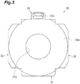
- FIG. 3 is a side view of the swashplate illustrated in FIG. 1 viewed from a side of a sliding contact surface.
- FIG. 4 is a side view of the swashplate illustrated in FIG. 1 viewed on a side opposite to the sliding contact surface.
- the swashplate 30 includes a body portion 31, a pair of sliding portions 32, and a pressed portion 33.
- the body portion 31 has a substantially plate shape, and the center portion thereof is provided with a through-hole 31a through which the above-described rotating shaft 20 is inserted.
- the pair of sliding portions 32 are provided at positions with the body portion 31 interposed therebetween to be integrated with the body portion 31.
- the rear surface side of the body portion 31 and the sliding portions 32 become a flat surface 30a as illustrated in FIG. 3 , and this surface is the sliding contact surface, which will be described later.
- the front surface side of the body portion 31 and the sliding portions 32 has a shape in which the sliding portions 32 protrude from the body portion 31 as illustrated in FIGS. 2 and 4 .
- the section of the sliding portion 32 has a half-moon shape (D shape), and has a sliding surface 32a which is curved at a predetermined curvature so as to be convex toward the front surface side.
- the pressed portion 33 which extends upward from the body portion 31 is provided.
- an accommodation hole 33a is formed, and a cylindrical member 33b, which will be described later, is disposed in the accommodation hole 33a.
- the cylindrical member 33b may be disposed in a fixed state so as not to be turned, or may be disposed so as to be turned.
- a protruding portion 33c and a planar portion 33d with which the tip end portion of the swashplate return spring 60 is engaged are formed on the front surface side in the pressed portion 33.
- the position of the swashplate 30 is held by a swashplate receiving member 34 disposed on the front surface side thereof.
- the swashplate receiving member 34 has a support surface 34a having substantially the same curvature as that of the sliding surface 32a of the sliding portion 32 of the swashplate 30 described above.
- the swashplate 30 is disposed so as to cause the sliding surface 32a of the sliding portion 32 to come into contact with the support surface 34a of the swashplate receiving member 34 and is thus supported by the swashplate receiving member 34 to be oscillated along the curvature.
- the swashplate 30 is capable of turning (regarded as tilting or regarded as rotating) about the center X of curvature of the support surface 34a of the swashplate receiving member 34 as the origin.
- the center X of curvature is also the center of curvature of the sliding surface 32a of the sliding portion 32 of the swashplate 30.
- the center X of curvature can be defined as a point at a constant distance (shortest distance) from the sliding contact surface 30a regardless of the turning position of the swashplate 30.
- the center of curvature is referred to as a turning center X.
- the turning center X is denoted by a dot.
- the line of the turning center X extends in an inward direction (a direction perpendicular to the figure).
- the swashplate 30 is disposed so as to turn about the turning center X and change the inclination that defines the stroke of the piston 16.
- the inclination can be defined as an angle with respect to a straight line perpendicular to the axial line of the rotating shaft 20.
- the inclination is defined as an angle of the sliding contact surface 30a with respect to the straight line perpendicular to the axial line of the rotating shaft 20.
- the sliding contact surface 30a on the rear surface side of the swashplate 30 faces the cylinder block 14 side.
- the head (one end portion) of each piston 16 protruding from the cylinder block 14 comes into sliding contact with the sliding contact surface 30a via a shoe 36.
- the shoe 36 to which the head of the piston 16 attached is held in a disk-shaped retainer 35 having a hole into which the shoe 36 is inserted.
- the stroke of each piston 16 defined by the inclination of the swashplate 30 is reciprocated, and the cylinder bore 14a alternately communicates with a suction port 40a and a discharge port 40b forming an arc shape, which are provided to penetrate through the valve plate 40. Accordingly, hydraulic oil is suctioned into the cylinder bore 14a from the suction port 40a, and the hydraulic oil in the cylinder bore 14a is discharged from the discharge port 40b due to a pump action.
- a suction passage 10d and a discharge passage 10e are formed in the rear housing 10c to respectively communicate with the suction port 40a and the discharge port 40b.
- the pump 1 is further provided with a control piston 50 provided on the rear surface side of the swashplate 30, that is, on the cylinder block 14 side.
- the control piston 50 is provided at a side portion of the center housing 10b of the pump housing 10, and includes a housing 52 that communicates with the crank chamber 12 and a piston portion 58 that reciprocates in the housing 52.
- the housing 52 has a substantially cylindrical shape extending in a direction inclined with respect to the rotating shaft 20 so as to cause the piston portion 58 to face the pressed portion 33 of the swashplate 30.
- a piston accommodation chamber 56 is defined in the housing 52, and the piston portion 58 is accommodated in the piston accommodation chamber 56.
- the piston portion 58 has a columnar external shape.
- the diameter of the piston portion 58 is designed such that there is no gap from the inner wall surface of the piston accommodation chamber 56 and the piston portion 58 slides in the piston accommodation chamber 56.
- the end surface of the piston portion 58 on the swashplate 30 is a planar shape and can move to a position that comes into contact with the cylindrical member 33b in the pressed portion 33 of the swashplate 30. As illustrated in FIG. 1 , the end surface of the piston portion 58 on the swashplate 30 side, which is a pressing portion, comes into contact with the cylindrical member 33b of the pressed portion 33 of the swashplate 30 to always press the cylindrical member 33b with a predetermined pressing force.
- a space between the piston portion 58 and the screw 54 in the piston accommodation chamber 56 functions as a control chamber 56a into which the hydraulic oil flows.
- the pressure in the control chamber 56a (hereinafter, referred to as control pressure) is changed due to the inflow of the hydraulic oil.
- the control piston 50 causes the piston portion 58 to slide due to a change in the control pressure and press the swashplate 30 from the cylinder block 14 side. Accordingly, the control piston 50 adjusts the inclination of the swashplate 30 between the maximum inclination, at which the discharge capacity of the hydraulic oil is maximized, and the minimum inclination, at which the discharge capacity of the hydraulic oil is minimized.
- the pump 1 further includes the swashplate return spring 60 which is a cylindrical spiral shape (coil spring) extending in one direction on the front surface side of the swashplate 30. That is, the swashplate return spring 60 is disposed on the side opposite to the control piston 50 with respect to the sliding contact surface 30a of the swashplate 30. Specifically, the base end portion of the swashplate return spring 60 is accommodated in a spring chamber 70 formed in the front housing 10a of the pump housing 10.
- the swashplate return spring 60 is a cylindrical spiral shape (coil spring) extending in one direction on the front surface side of the swashplate 30. That is, the swashplate return spring 60 is disposed on the side opposite to the control piston 50 with respect to the sliding contact surface 30a of the swashplate 30. Specifically, the base end portion of the swashplate return spring 60 is accommodated in a spring chamber 70 formed in the front housing 10a of the pump housing 10.
- the spring chamber 70 is formed in parallel to the rotating shaft 20, and the swashplate return spring 60 extends toward the swashplate 30 from the spring chamber 70.
- the swashplate return spring 60 is disposed so that the axial direction thereof is parallel to the rotating shaft 20.
- the tip end portion of the swashplate return spring 60 abuts the front surface of the pressed portion 33 of the swashplate 30 described above and is engaged with the protruding portion 33c and the planar portion 33d formed on the front surface.
- the swashplate return spring 60 is not fixed to the spring chamber 70 and the swashplate 30 and the position and posture thereof are held in a state of being interposed between the spring chamber 70 and the pressed portion 33.
- a seat surface 60a of the base end portion abuts the bottom wall of the spring chamber 70, and a seat surface 60b of the tip end portion abuts the pressed portion 33 of the swashplate 30. Accordingly, the swashplate return spring 60 is compressed such that the swashplate 30 is biased toward the cylinder block side with respect to the sliding contact surface 30a.
- the swashplate return spring 60 is a wire spring formed by processing a metallic wire rod such as SWP-B.
- an action position which is a position at which the pressing force of the piston portion 58 which is the pressing portion acts on the pressed portion 33 will be described in detail.
- the position at which the pressing force of the piston portion 58 acts on the pressed portion 33 is, for example, a position at which the end surface of the piston portion 58 on the swashplate 30 side comes into contact with the cylindrical member 33b of the pressed portion 33 of the swashplate 30 and presses the cylindrical member 33b with a predetermined pressing force.
- the position at which the end surface of the piston portion 58 on the swashplate 30 side comes into contact with the cylindrical member 33b of the pressed portion 33 of the swashplate 30 and presses the cylindrical member 33b with a predetermined pressing force is referred to as an action position of the pressing force of the piston portion 58.
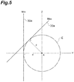
- FIG. 5 is a view schematically illustrating the positional relationship between the sliding contact surface 30a of the swashplate 30 and the turning center X of the swashplate 30.
- the turning center X is denoted by a dot.
- the line of the turning center X extends in an inward direction (a direction perpendicular to the figure).
- a distance d from the sliding contact surface 30a of the swashplate 30 to the turning center X at the maximum inclination indicated by "Max” and a distance d from the sliding contact surface 30a of the swashplate 30 to the turning center X at the minimum inclination indicated by “Min” are the same. That is, the distance of the turning center X from the sliding contact surface 30a is constant regardless of the inclination of the swashplate 30.
- an imaginary circle E that touches both the sliding contact surface 30a of the swashplate 30 at the maximum inclination and the sliding contact surface 30a of the swashplate 30 at the minimum inclination is drawn as a circle having the turning center X as its center. That is, the turning center X is the axial line of a column having, as its section, the imaginary circle E that touches the sliding contact surface 30a of the swashplate 30 regardless of the inclination of the swashplate 30.
- the parallel reference line Y is a straight line which is parallel to a direction in which the pressing force of the piston portion 58 acts and passes through the turning center X.
- a straight line that is perpendicular to the parallel reference line Y and passes through the turning center X is defined as the vertical reference line Z.
- FIG. 6 is a schematic view illustrating variation in the action position of the pressing force of the piston portion 58 of the control piston 50.
- the parallel reference line Y, the vertical reference line Z, and the turning center X shown in FIG. 5 are shown.
- the pressing force of the piston portion 58 is indicated by a pressing force F
- a line of action of the pressing force F when the inclination of the swashplate 30 is the maximum inclination is indicated by a line of action S1
- a line of action when the inclination of the swashplate 30 is the minimum inclination is indicated by a line of action S2.
- a direction in which the pressing force F acts is a direction parallel to the parallel reference line Y.
- variation in the action position of the pressing force of the piston portion 58 in the pump 1 according to the embodiment is indicated by a double-headed arrow A.
- the double-headed arrow A represents that the action position of the pressing force F varies between a position of the pressing force F when the inclination of the swashplate 30 is the maximum inclination (hereinafter, referred to as a first action position) A1, and a position of the pressing force F when the inclination of the swashplate 30 is the minimum inclination (hereinafter, referred to as a second action position) A2.
- the angular difference between the maximum inclination and the minimum inclination of the swashplate 30 is indicated by ⁇ . As illustrated in FIG.
- the action position of the pressing force F moves between the first action position A1 and the second action position A2 along an arc of the imaginary circle having the turning center X as its center. This is because the distance between the cylindrical member 33b on which the pressing force F acts and the turning center X is always constant regardless of the inclination.
- the vertical reference line Z passes between the first action position A1 when the inclination of the swashplate 30 is the maximum inclination and the second action position A2 when the inclination of the swashplate 30 is the minimum inclination. That is, the vertical reference line Z is interposed between the first action position A1 when the inclination of the swashplate 30 is the maximum inclination and the second action position A2 when the inclination of the swashplate 30 is the minimum inclination.
- the action position of the pressing force F barely displaces in the directions of the vertical reference line Z. Therefore, the distance between the pressing force F and the turning center X when the inclination of the swashplate 30 is the maximum inclination (that is, the length of a moment arm of the pressing force F about the turning center X) La 1 and the distance between the pressing force F and the turning center X when the inclination of the swashplate 30 is the minimum inclination La 2 barely change.
- FIG. 7 is a schematic view illustrating variation in the action position of the pressing force F of the piston portion 58 as a comparative example of the embodiment in addition to the case of FIG. 6 .
- the vertical reference line Z passes between the first action position A1 and the second action position A2 is indicated by the double-headed arrow A as in FIG. 6
- cases where the vertical reference line Z does not pass between a first action position and a second action position are indicated by double-headed arrows B and C.
- the difference ⁇ between the maximum inclination and the minimum inclination is the same as the difference ⁇ of the double-headed arrow A described above.
- the double-headed arrow B indicates variation in the action position of the pressing force F in a case where both a first action position B1 and a second action position B2 are positioned on the swashplate return spring 60 side in relation to the vertical reference line Z.
- the action position of the pressing force F gradually moves in a downward direction and significantly displaces in the directions of the vertical reference line Z.
- the length Lb 2 of the moment arm of the pressing force F when the inclination of the swashplate 30 is the minimum inclination becomes shorter than the length Lb 1 of the moment arm of the pressing force F when the inclination of the swashplate 30 is the maximum inclination.
- the double-headed arrow C indicates variation in the action position of the pressing force F in a case where both a first action position C1 and a second action position C2 are positioned on the control piston 50 side in relation to the vertical reference line Z.
- the action position of the pressing force F gradually moves in an upward direction and significantly displaces in the directions of the vertical reference line Z.
- the length Lc 2 of the moment arm of the pressing force F when the inclination of the swashplate 30 is the minimum inclination becomes longer than the length LC 1 of the moment arm of the pressing force F when the inclination of the swashplate 30 is the maximum inclination.
- the position at which the pressing force F of the piston portion 58 of the control piston 50 acts on the cylindrical member 33b of the pressed portion 33 is on the vertical reference line Z or near the vertical reference line Z. Therefore, even when the inclination of the swashplate 30 displaces from the maximum inclination to the minimum inclination, the length of the moment arm of the pressing force F barely changes, and the amount of variation in the moment of the pressing force F due to the displacement of the inclination of the swashplate 30 can be suppressed. As a result, controllability over the inclination of the swashplate 30 can be improved.
- the positional relationship in which the vertical reference line Z passes between the first action position A1 and the second action position A2, that is, the positional relationship in which the vertical reference line Z is interposed between the first action position A1 and the second action position A2 includes a positional relationship in which the vertical reference line Z overlaps the first action position A1 or the second action position A2.
- the positional relationship between the first action position A1, the second action position A2, and the vertical reference line Z may be an embodiment in which the vertical reference line Z passes through a midpoint P which is the point that bisects a straight line that connects the first action position A1 and the second action position A2.
- the vertical reference line is coincident with the perpendicular bisector of the straight line that connects the first action position A1 and the second action position A2.
- the length La 1 of the moment arm when the inclination of the swashplate 30 is the maximum inclination and the length La 2 of the moment arm when the inclination of the swashplate 30 is the minimum inclination can be equal to each other. That is, the length of the moment arm does not excessively increases in any of cases where the inclination of the swashplate 30 is the maximum inclination or the minimum inclination. Therefore, the amount of variation of the moment due to the displacement of the inclination of the swashplate 30 can be minimized. Accordingly, controllability over the inclination of the swashplate 30 can be further improved.
- the swashplate 30 is not limited to that in the embodiment.
- a swashplate 130 having a shape illustrated in FIG. 9 may be employed instead of the swashplate 30, a swashplate 130 having a shape illustrated in FIG. 9 may be employed.
- the swashplate 130 includes a pair of rotating shaft portions 132 instead of the pair of sliding portions 32 of the swashplate 30.
- the above-described swashplate 30 has a form that oscillates about the turning center X by cooperation between the sliding portions 32 and the swashplate receiving member 34.
- the swashplate 130 can oscillate about the turning center X since the pair of rotating shaft portions 132 having a columnar shape extending along the turning center X are rotatably held in the crank chamber 12.
- the swashplate 130 also includes a disk-shaped body portion 131 having the same function as that of the body portion 31 of the swashplate 30 described above.
- the body portion 131 includes a sliding contact surface 130a, which is the same as the sliding contact surface 30a, on the rear surface side thereof and further includes a pressed portion 133 which is the same as the pressed portion 33 at the upper portion thereof.
- the swashplate 130 illustrated in FIG. 8 has functions which are the same as or equivalent to those of the swashplate 30 described above. Moreover, since the swashplate 130 includes the pair of rotating shaft portions 132, the swashplate receiving member 34 described above becomes unnecessary, and simplification of the configuration of the pump 1 can be achieved.
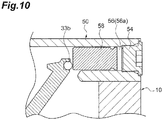
- FIG. 10 is a schematic sectional view illustrating main parts of a variable capacity piston pump according to a modification example.
- the vicinity of the control piston 50 in the variable capacity piston pump according to the modification example is enlarged to be illustrated.
- the piston portion 58 of the control piston 50 is disposed in parallel to the rotating shaft 20.
- the pump 1 is generally designed on the basis of the axial line of the rotating shaft 20. Therefore, when the piston portion 58 of the control piston 50 is disposed in parallel to the rotating shaft 20, design of the control piston 50 or the pump housing 10 (particularly the center housing 10b in which the control piston 50 is provided) is facilitated.
- the dimensions (diameter dimension) of the center housing 10b are greater than those of the front housing 10a or the rear housing 10c.
- the piston portion 58 of the control piston 50 is disposed in parallel to the rotating shaft 20, an increase in the dimensions is suppressed. As a result, miniaturization of the variable capacity piston pump can be realized.
Landscapes
- Engineering & Computer Science (AREA)
- Mechanical Engineering (AREA)
- General Engineering & Computer Science (AREA)
- Reciprocating Pumps (AREA)
Description
- The present invention relates to a variable capacity piston pump.
- As a variable capacity piston pump in the related art, for example, as described in Patent Literature 1 (Japanese Unexamined Patent Publication No.
2006-348911 - The variable capacity piston pump described in
Patent Literature 1 includes a control piston which presses the swashplate and a swashplate return spring which biases the swashplate from a side opposite to the control piston. As the control pressure of the control piston is changed, the magnitude of a pressing force exerted on the swashplate is changed. By controlling the magnitude of the pressing force, the inclination of the swashplate is adjusted. Specifically, when the pressing force of the control piston is decreased, the inclination of the swashplate is increased by the biasing force of the swashplate return spring. When the pressing force of the control piston is increased, the inclination of the swashplate is decreased. When the inclination is changed, the swashplate turns about a certain turning center. - The inventors found that when the inclination of the swashplate is changed, the distance between the pressing force of the control piston and the turning center (that is, the length of a moment arm of the pressing force of the control piston about the turning center) is changed, resulting in deterioration in controllability over the inclination of the swashplate.
- For example, when the control piston presses the swashplate to decrease the inclination of the swashplate, in a case where the length of the moment arm is shortened as the inclination of the swashplate is decreased, the moment of the pressing force of the control piston about the turning center is decreased, and it becomes difficult for the swashplate to rotate. In this case, the responsiveness of the inclination of the swashplate to the pressing force of the control piston deteriorates (for example, the response speed becomes slow), and inappropriate control over the inclination of the swashplate may be incurred.
- In contrast, when the control piston presses the swashplate to decrease the inclination of the swashplate, in a case where the length of the moment arm is lengthened as the inclination of the swashplate is decreased, the moment of the pressing force of the control piston about the turning center is increased, and the swashplate more easily rotates. In this case, the response of the inclination of the swashplate to the pressing force of the control piston becomes excessively sensitive (for example, the response speed becomes excessively fast), and inappropriate control over the inclination of the swashplate may be incurred.
- An object of various aspects of the present invention is to provide a variable capacity piston pump which achieves an improvement in controllability over the inclination of a swashplate.
- According to an aspect of the present invention, there is provided a variable capacity piston pump performing suction and discharge of a hydraulic fluid by reciprocation of a piston in a cylinder block rotating integrally with a rotating shaft, the stroke of the reciprocation of the piston depending on an inclination of a swashplate, wherein the swashplate includes a sliding contact surface contacting slidably with one end portion of the piston via a shoe, the swashplate being disposed to enable to turn about a turning center to change the inclination that defines the stroke of the piston, the variable capacity piston pump comprising: a pressing portion disposed on one side with respect to the sliding contact surface of the swashplate, the pressing portion causing a pressing force to act along one direction by pressing a pressed portion of the swashplate to adjust the inclination of the swashplate between a maximum inclination and a minimum inclination, wherein a discharge capacity of the hydraulic fluid is maximized at the maximum inclination and the discharge capacity of the hydraulic fluid is minimized at the minimum inclination, and a swashplate return spring disposed on the other side with respect to the sliding contact surface of the swashplate, the swashplate return spring biasing the pressed portion of the swashplate toward the one side of the sliding contact surface, wherein the pressed portion is capable of taking a first action position and a second action position, wherein the first action position is a position at which the pressing force of the pressing portion acts when the inclination of the swashplate is the maximum inclination and the second action position is a position at which the pressing force of the pressing portion acts when the inclination of the swashplate is the minimum inclination, and wherein there is a positional relationship in which a vertical reference line passes between the first action position and the second action position, the vertical reference line being a straight line perpendicular to a parallel reference line and passing through the turning center of the swashplate, the parallel reference line being a straight line parallel to a direction in which the pressing force of the pressing portion acts and passing through the turning center of the swashplate.
- In the variable capacity piston pump described above, there is a positional relationship in which the vertical reference line passes between the first action position which is the position at which the pressing force of the pressing portion acts on the pressed portion when the inclination of the swashplate is the maximum inclination and the second action position which is the position at which the pressing force of the pressing portion acts on the pressed portion when the inclination of the swashplate is the minimum inclination. When the position at which the pressing force of the pressing portion acts on the pressed portion is on the vertical reference line or near the vertical reference line, the length of a moment arm of the pressing force due to the pressing portion barely changes. In the variable capacity piston pump described above, since the first action position and the second action position are positioned with the vertical reference line interposed therebetween, the position at which the pressing force of the pressing portion acts on the pressed portion is on the vertical reference line or near the vertical reference line. Therefore, even when the inclination of the swashplate changes from the maximum inclination to the minimum inclination, the length of the moment arm of the pressing force barely changes. Accordingly, the amount of variation in the moment of the pressing force can be suppressed regardless of the inclination of the swashplate. As a result, controllability over the inclination of the swashplate can be improved.
- According to another aspect of the present invention, in the variable capacity piston pump, there may be a positional relationship in which the vertical reference line passes through a midpoint between the first action position and the second action position. In this case, the length of the moment arm when the inclination of the swashplate is the maximum inclination and the length of the moment arm when the inclination of the swashplate is the minimum inclination can be equal to each other. Therefore, the amount of a change in the length of the moment arm of the pressing force while the inclination of the swashplate displaces from the maximum inclination to the minimum inclination can be minimized. Accordingly, the amount of variation of the moment of the pressing force due to the displacement of the inclination of the swashplate can be suppressed to the maximum degree. As a result, controllability over the inclination of the swashplate can be further improved.
- According to another aspect of the present invention, in the variable capacity piston pump, the pressing portion may be disposed in parallel to the rotating shaft. In this case, design of the variable capacity piston pump can be facilitated.
- According to the various aspects of the present invention, a variable capacity piston pump which achieves an improvement in controllability over the inclination of a swashplate is provided.
-
-
FIG. 1 is a schematic sectional view illustrating a variable capacity piston pump according to an embodiment of the present invention. -
FIG. 2 is a perspective view of a swashplate illustrated inFIG. 1 . -
FIG. 3 is a side view of the swashplate illustrated inFIG. 1 viewed from a side of a sliding contact surface. -
FIG. 4 is a side view of the swashplate illustrated inFIG. 1 viewed on a side opposite to the sliding contact surface. -
FIG. 5 is a view schematically illustrating the positional relationship between the sliding contact surface of the swashplate and a turning center of the swashplate. -
FIG. 6 is a schematic view illustrating variation in an action position of a pressing force of a piston portion. -
FIG. 7 is a schematic view illustrating variation in the action position of the pressing force of the piston portion as a comparative example of the embodiment in addition to the case ofFIG. 6 . -
FIG. 8 is a schematic view illustrating variation in the action position of the pressing force of the piston portion at a position different from that ofFIG. 6 . -
FIG. 9 is a perspective view illustrating a swashplate according to a modification example. -
FIG. 10 is a schematic sectional view illustrating main parts of a variable capacity piston pump according to a modification example. - Hereinafter, an embodiment of the present invention will be described in detail with reference to the accompanying drawings. In the description, like elements which are the same or having the same function are denoted by like reference numerals, and overlapping description thereof will be omitted.
- First, a variable capacity piston pump (hereinafter, "a pump") according to the embodiment will be described with reference to
FIG. 1 . Apump 1 includes apump housing 10, a rotatingshaft 20, and acylinder block 14. - The
pump housing 10 is configured by bonding afront housing 10a, acenter housing 10b, and arear housing 10c together, and has acrank chamber 12 therein. - Most of the rotating
shaft 20 is accommodated in thecrank chamber 12 of thepump housing 10, and only one end portion thereof protrudes from thepump housing 10. The rotatingshaft 20 is rotatably held in thecrank chamber 12 by a bearing. The end portion of the rotatingshaft 20 protruding from thepump housing 10 is connected to a power take-off (not illustrated) such that the entirety of the rotatingshaft 20 is driven to rotate by an engine. - The
cylinder block 14 is also accommodated in thecrank chamber 12 of thepump housing 10. Thecylinder block 14 is spline-fitted to the rotatingshaft 20 so as to rotate integrally with the rotatingshaft 20. In thecylinder block 14, a plurality ofcylinder bores 14a, each including an opening on a side of the protruding end portion of the rotatingshaft 20, are provided, and the plurality ofcylinder bores 14a are disposed with intervals therebetween at a predetermined angle around the rotatingshaft 20 in thecylinder block 14. In addition, in each of the plurality ofcylinder bores 14a, a piston 16a having a head protruding toward the side of the protruding end portion of the rotatingshaft 20 is accommodated. - A
swashplate 30 is further accommodated in thecrank chamber 12 of thepump housing 10. Hereinafter, the configuration of theswashplate 30 will be described with reference toFIGS. 2 to 4 .FIG. 2 is a perspective view of theswashplate 30 illustrated inFIG. 1 .FIG. 3 is a side view of the swashplate illustrated inFIG. 1 viewed from a side of a sliding contact surface.FIG. 4 is a side view of the swashplate illustrated inFIG. 1 viewed on a side opposite to the sliding contact surface. - As illustrated in
FIGS. 2 to 4 , theswashplate 30 includes abody portion 31, a pair of slidingportions 32, and a pressedportion 33. - The
body portion 31 has a substantially plate shape, and the center portion thereof is provided with a through-hole 31a through which the above-describedrotating shaft 20 is inserted. The pair of slidingportions 32 are provided at positions with thebody portion 31 interposed therebetween to be integrated with thebody portion 31. - The rear surface side of the
body portion 31 and the slidingportions 32 become aflat surface 30a as illustrated inFIG. 3 , and this surface is the sliding contact surface, which will be described later. On the other hand, the front surface side of thebody portion 31 and the slidingportions 32 has a shape in which the slidingportions 32 protrude from thebody portion 31 as illustrated inFIGS. 2 and4 . The section of the slidingportion 32 has a half-moon shape (D shape), and has a slidingsurface 32a which is curved at a predetermined curvature so as to be convex toward the front surface side. - In addition, in the
body portion 31, the pressedportion 33 which extends upward from thebody portion 31 is provided. On the rear surface side in the pressedportion 33, anaccommodation hole 33a is formed, and acylindrical member 33b, which will be described later, is disposed in theaccommodation hole 33a. In addition, thecylindrical member 33b may be disposed in a fixed state so as not to be turned, or may be disposed so as to be turned. In addition, on the front surface side in the pressedportion 33, at a position biased by the tip end portion of aswashplate return spring 60, a protrudingportion 33c and aplanar portion 33d with which the tip end portion of theswashplate return spring 60 is engaged are formed. - Returning to
FIG. 1 , the position of theswashplate 30 is held by aswashplate receiving member 34 disposed on the front surface side thereof. Theswashplate receiving member 34 has asupport surface 34a having substantially the same curvature as that of the slidingsurface 32a of the slidingportion 32 of theswashplate 30 described above. Theswashplate 30 is disposed so as to cause the slidingsurface 32a of the slidingportion 32 to come into contact with thesupport surface 34a of theswashplate receiving member 34 and is thus supported by theswashplate receiving member 34 to be oscillated along the curvature. More specifically, theswashplate 30 is capable of turning (regarded as tilting or regarded as rotating) about the center X of curvature of thesupport surface 34a of theswashplate receiving member 34 as the origin. The center X of curvature is also the center of curvature of the slidingsurface 32a of the slidingportion 32 of theswashplate 30. In addition, the center X of curvature can be defined as a point at a constant distance (shortest distance) from the slidingcontact surface 30a regardless of the turning position of theswashplate 30. In the following description, the center of curvature is referred to as a turning center X. In addition, inFIG. 1 , the turning center X is denoted by a dot. However, in practice, the line of the turning center X extends in an inward direction (a direction perpendicular to the figure). - The
swashplate 30 is disposed so as to turn about the turning center X and change the inclination that defines the stroke of thepiston 16. For example, the inclination can be defined as an angle with respect to a straight line perpendicular to the axial line of therotating shaft 20. In the embodiment, the inclination is defined as an angle of the slidingcontact surface 30a with respect to the straight line perpendicular to the axial line of therotating shaft 20. - The sliding
contact surface 30a on the rear surface side of theswashplate 30 faces thecylinder block 14 side. The head (one end portion) of eachpiston 16 protruding from thecylinder block 14 comes into sliding contact with the slidingcontact surface 30a via ashoe 36. Theshoe 36 to which the head of thepiston 16 attached is held in a disk-shapedretainer 35 having a hole into which theshoe 36 is inserted. When thecylinder block 14 is rotated along with the rotatingshaft 20, eachpiston 16 rotates about the rotatingshaft 20 while sliding on the slidingcontact surface 30a via theshoe 36. - As the
swashplate 30 is turned and inclined about the turning center X, the end portion of the head side (the left end portion inFIG. 1 ) of eachpiston 16 accommodated in thecylinder block 14 comes in pressing contact via theshoe 36, and thecylinder block 14 comes into pressing contact with avalve plate 40 fixed to the inner end wall surface of therear housing 10c. - In addition, as the
cylinder block 14 and therotating shaft 20 rotate integrally with each other, the stroke of eachpiston 16 defined by the inclination of theswashplate 30 is reciprocated, and the cylinder bore 14a alternately communicates with asuction port 40a and adischarge port 40b forming an arc shape, which are provided to penetrate through thevalve plate 40. Accordingly, hydraulic oil is suctioned into the cylinder bore 14a from thesuction port 40a, and the hydraulic oil in thecylinder bore 14a is discharged from thedischarge port 40b due to a pump action. In addition, asuction passage 10d and adischarge passage 10e are formed in therear housing 10c to respectively communicate with thesuction port 40a and thedischarge port 40b. - The
pump 1 is further provided with acontrol piston 50 provided on the rear surface side of theswashplate 30, that is, on thecylinder block 14 side. Thecontrol piston 50 is provided at a side portion of thecenter housing 10b of thepump housing 10, and includes ahousing 52 that communicates with thecrank chamber 12 and apiston portion 58 that reciprocates in thehousing 52. Thehousing 52 has a substantially cylindrical shape extending in a direction inclined with respect to therotating shaft 20 so as to cause thepiston portion 58 to face the pressedportion 33 of theswashplate 30. - One opening of the openings of the
housing 52 distant from theswashplate 30 is blocked by ascrew 54. Accordingly, apiston accommodation chamber 56 is defined in thehousing 52, and thepiston portion 58 is accommodated in thepiston accommodation chamber 56. - The
piston portion 58 has a columnar external shape. The diameter of thepiston portion 58 is designed such that there is no gap from the inner wall surface of thepiston accommodation chamber 56 and thepiston portion 58 slides in thepiston accommodation chamber 56. The end surface of thepiston portion 58 on theswashplate 30 is a planar shape and can move to a position that comes into contact with thecylindrical member 33b in the pressedportion 33 of theswashplate 30. As illustrated inFIG. 1 , the end surface of thepiston portion 58 on theswashplate 30 side, which is a pressing portion, comes into contact with thecylindrical member 33b of the pressedportion 33 of theswashplate 30 to always press thecylindrical member 33b with a predetermined pressing force. - A space between the
piston portion 58 and thescrew 54 in thepiston accommodation chamber 56 functions as acontrol chamber 56a into which the hydraulic oil flows. The pressure in thecontrol chamber 56a (hereinafter, referred to as control pressure) is changed due to the inflow of the hydraulic oil. Thecontrol piston 50 causes thepiston portion 58 to slide due to a change in the control pressure and press the swashplate 30 from thecylinder block 14 side. Accordingly, thecontrol piston 50 adjusts the inclination of theswashplate 30 between the maximum inclination, at which the discharge capacity of the hydraulic oil is maximized, and the minimum inclination, at which the discharge capacity of the hydraulic oil is minimized. - The
pump 1 further includes theswashplate return spring 60 which is a cylindrical spiral shape (coil spring) extending in one direction on the front surface side of theswashplate 30. That is, theswashplate return spring 60 is disposed on the side opposite to thecontrol piston 50 with respect to the slidingcontact surface 30a of theswashplate 30. Specifically, the base end portion of theswashplate return spring 60 is accommodated in aspring chamber 70 formed in thefront housing 10a of thepump housing 10. - In the embodiment, the
spring chamber 70 is formed in parallel to therotating shaft 20, and theswashplate return spring 60 extends toward the swashplate 30 from thespring chamber 70. As a result, theswashplate return spring 60 is disposed so that the axial direction thereof is parallel to therotating shaft 20. The tip end portion of theswashplate return spring 60 abuts the front surface of the pressedportion 33 of theswashplate 30 described above and is engaged with the protrudingportion 33c and theplanar portion 33d formed on the front surface. Theswashplate return spring 60 is not fixed to thespring chamber 70 and the swashplate 30 and the position and posture thereof are held in a state of being interposed between thespring chamber 70 and the pressedportion 33. - In other words, regarding the seat surfaces (spring end surfaces) of the
swashplate return spring 60, aseat surface 60a of the base end portion abuts the bottom wall of thespring chamber 70, and aseat surface 60b of the tip end portion abuts the pressedportion 33 of theswashplate 30. Accordingly, theswashplate return spring 60 is compressed such that theswashplate 30 is biased toward the cylinder block side with respect to the slidingcontact surface 30a. In addition, theswashplate return spring 60 is a wire spring formed by processing a metallic wire rod such as SWP-B. - Next, with reference to
Figs 5 to 7 , an action position which is a position at which the pressing force of thepiston portion 58 which is the pressing portion acts on the pressedportion 33 will be described in detail. Here, the position at which the pressing force of thepiston portion 58 acts on the pressedportion 33 is, for example, a position at which the end surface of thepiston portion 58 on theswashplate 30 side comes into contact with thecylindrical member 33b of the pressedportion 33 of theswashplate 30 and presses thecylindrical member 33b with a predetermined pressing force. Hereinafter, the position at which the end surface of thepiston portion 58 on theswashplate 30 side comes into contact with thecylindrical member 33b of the pressedportion 33 of theswashplate 30 and presses thecylindrical member 33b with a predetermined pressing force is referred to as an action position of the pressing force of thepiston portion 58. - First, references such as the turning center X, the vertical reference line and the parallel reference line for the action position of the pressing force of the
piston portion 58 will be described.FIG. 5 is a view schematically illustrating the positional relationship between the slidingcontact surface 30a of theswashplate 30 and the turning center X of theswashplate 30. In addition, inFIG. 5 , the turning center X is denoted by a dot. However, the line of the turning center X extends in an inward direction (a direction perpendicular to the figure). - As illustrated in
FIG. 5 , a distance d from the slidingcontact surface 30a of theswashplate 30 to the turning center X at the maximum inclination indicated by "Max" and a distance d from the slidingcontact surface 30a of theswashplate 30 to the turning center X at the minimum inclination indicated by "Min" are the same. That is, the distance of the turning center X from the slidingcontact surface 30a is constant regardless of the inclination of theswashplate 30. In addition, in a section, an imaginary circle E that touches both the slidingcontact surface 30a of theswashplate 30 at the maximum inclination and the slidingcontact surface 30a of theswashplate 30 at the minimum inclination is drawn as a circle having the turning center X as its center. That is, the turning center X is the axial line of a column having, as its section, the imaginary circle E that touches the slidingcontact surface 30a of theswashplate 30 regardless of the inclination of theswashplate 30. - The parallel reference line Y is a straight line which is parallel to a direction in which the pressing force of the
piston portion 58 acts and passes through the turning center X. A straight line that is perpendicular to the parallel reference line Y and passes through the turning center X is defined as the vertical reference line Z. -
FIG. 6 is a schematic view illustrating variation in the action position of the pressing force of thepiston portion 58 of thecontrol piston 50. InFIG. 6 , the parallel reference line Y, the vertical reference line Z, and the turning center X shown inFIG. 5 are shown. InFIG. 6 , furthermore, the pressing force of thepiston portion 58 is indicated by a pressing force F, a line of action of the pressing force F when the inclination of theswashplate 30 is the maximum inclination is indicated by a line of action S1, and a line of action when the inclination of theswashplate 30 is the minimum inclination is indicated by a line of action S2. In addition, a direction in which the pressing force F acts is a direction parallel to the parallel reference line Y. - In
FIG. 6 , variation in the action position of the pressing force of thepiston portion 58 in thepump 1 according to the embodiment is indicated by a double-headed arrow A. The double-headed arrow A represents that the action position of the pressing force F varies between a position of the pressing force F when the inclination of theswashplate 30 is the maximum inclination (hereinafter, referred to as a first action position) A1, and a position of the pressing force F when the inclination of theswashplate 30 is the minimum inclination (hereinafter, referred to as a second action position) A2. The angular difference between the maximum inclination and the minimum inclination of theswashplate 30 is indicated by θ. As illustrated inFIG. 6 , the action position of the pressing force F moves between the first action position A1 and the second action position A2 along an arc of the imaginary circle having the turning center X as its center. This is because the distance between thecylindrical member 33b on which the pressing force F acts and the turning center X is always constant regardless of the inclination. - As indicated by the double-headed arrow A of
FIG. 6 , in thepump 1 according to the embodiment, for example, when viewed in a direction perpendicular to a plane parallel to the parallel reference line Y and the vertical reference line Z (a direction perpendicular to the figure), the vertical reference line Z passes between the first action position A1 when the inclination of theswashplate 30 is the maximum inclination and the second action position A2 when the inclination of theswashplate 30 is the minimum inclination. That is, the vertical reference line Z is interposed between the first action position A1 when the inclination of theswashplate 30 is the maximum inclination and the second action position A2 when the inclination of theswashplate 30 is the minimum inclination. - In a case where the first action position A1, the second action position A2, and the vertical reference line Z have this positional relationship, as illustrated in
FIG. 6 , the action position of the pressing force F moves just beside the action position in the range of the double-headed arrow A, and there is substantially no displacement in upward and downward directions (that is, directions of the vertical reference line Z) ofFIG. 6 . Therefore, even when the inclination of theswashplate 30 moves from the maximum inclination to the minimum inclination and accordingly the action position of the pressing force F moves from the first action position A1 to the second action position A2, there is substantially no displacement in the directions of the vertical reference line Z (a change in the height position of each of the lines of action S1 and S2 with respect to the parallel reference line Y). - As described above, while the inclination of the
swashplate 30 moves from the maximum inclination to the minimum inclination, the action position of the pressing force F barely displaces in the directions of the vertical reference line Z. Therefore, the distance between the pressing force F and the turning center X when the inclination of theswashplate 30 is the maximum inclination (that is, the length of a moment arm of the pressing force F about the turning center X) La1 and the distance between the pressing force F and the turning center X when the inclination of theswashplate 30 is the minimum inclination La2 barely change. That is, even when the inclination of theswashplate 30 moves from the maximum inclination to the minimum inclination, the length of the moment arm of the pressing force F about the turning center X barely changes. Therefore, the amount of variation in the moment of the pressing force F about the turning center X due to a change in the inclination of theswashplate 30 can be suppressed. -
FIG. 7 is a schematic view illustrating variation in the action position of the pressing force F of thepiston portion 58 as a comparative example of the embodiment in addition to the case ofFIG. 6 . InFIG. 7 , while the case where the vertical reference line Z passes between the first action position A1 and the second action position A2 is indicated by the double-headed arrow A as inFIG. 6 , cases where the vertical reference line Z does not pass between a first action position and a second action position are indicated by double-headed arrows B and C. In addition, in any case of the double-headed arrows B and C, the difference θ between the maximum inclination and the minimum inclination is the same as the difference θ of the double-headed arrow A described above. - The double-headed arrow B indicates variation in the action position of the pressing force F in a case where both a first action position B1 and a second action position B2 are positioned on the
swashplate return spring 60 side in relation to the vertical reference line Z. As illustrated inFIG. 7 , when the inclination of the swashplate 30 changes from the maximum inclination to the minimum inclination and accordingly the action position of the pressing force F moves from the first action position B1 to the second action position B2, the action position of the pressing force F gradually moves in a downward direction and significantly displaces in the directions of the vertical reference line Z. Therefore, regarding the case of the double-headed arrow B, the length Lb2 of the moment arm of the pressing force F when the inclination of theswashplate 30 is the minimum inclination becomes shorter than the length Lb1 of the moment arm of the pressing force F when the inclination of theswashplate 30 is the maximum inclination. - As described above, when the length of the moment arm of the pressing force F is shortened as the inclination of the
swashplate 30 is decreased, the moment of the pressing force F is decreased, and it is difficult for theswashplate 30 to rotate. Therefore, the responsiveness of the inclination of theswashplate 30 to the pressing force F of thepiston portion 58 deteriorates (for example, the response speed becomes slow), and the inclination of theswashplate 30 is not appropriately controlled. - The double-headed arrow C indicates variation in the action position of the pressing force F in a case where both a first action position C1 and a second action position C2 are positioned on the
control piston 50 side in relation to the vertical reference line Z. As illustrated inFIG. 7 , when the inclination of the swashplate 30 changes from the maximum inclination to the minimum inclination and accordingly the action position of the pressing force F moves from the first action position C1 to the second action position C2, the action position of the pressing force F gradually moves in an upward direction and significantly displaces in the directions of the vertical reference line Z. Therefore, regarding the case of the double-headed arrow C, the length Lc2 of the moment arm of the pressing force F when the inclination of theswashplate 30 is the minimum inclination becomes longer than the length LC1 of the moment arm of the pressing force F when the inclination of theswashplate 30 is the maximum inclination. - As described above, when the length of the moment arm of the pressing force F is lengthened as the inclination of the
swashplate 30 is decreased, the moment of the pressing force F is increased, and theswashplate 30 more easily rotate. Therefore, the response of the inclination of theswashplate 30 to the pressing force F of thepiston portion 58 becomes excessively sensitive (for example, the response speed becomes excessively fast), and the inclination of theswashplate 30 is also not appropriately controlled. - As described above, in the
pump 1 according to the embodiment, since the first action position A1 and the second action position A2 are positioned with the vertical reference line Z interposed therebetween, the position at which the pressing force F of thepiston portion 58 of thecontrol piston 50 acts on thecylindrical member 33b of the pressedportion 33 is on the vertical reference line Z or near the vertical reference line Z. Therefore, even when the inclination of theswashplate 30 displaces from the maximum inclination to the minimum inclination, the length of the moment arm of the pressing force F barely changes, and the amount of variation in the moment of the pressing force F due to the displacement of the inclination of theswashplate 30 can be suppressed. As a result, controllability over the inclination of theswashplate 30 can be improved. - In addition, the positional relationship in which the vertical reference line Z passes between the first action position A1 and the second action position A2, that is, the positional relationship in which the vertical reference line Z is interposed between the first action position A1 and the second action position A2 includes a positional relationship in which the vertical reference line Z overlaps the first action position A1 or the second action position A2.
- In addition, as indicated by the double-headed arrow A of
FIG. 8 , the positional relationship between the first action position A1, the second action position A2, and the vertical reference line Z may be an embodiment in which the vertical reference line Z passes through a midpoint P which is the point that bisects a straight line that connects the first action position A1 and the second action position A2. In this case, the vertical reference line is coincident with the perpendicular bisector of the straight line that connects the first action position A1 and the second action position A2. - At this time, the length La1 of the moment arm when the inclination of the
swashplate 30 is the maximum inclination and the length La2 of the moment arm when the inclination of theswashplate 30 is the minimum inclination can be equal to each other. That is, the length of the moment arm does not excessively increases in any of cases where the inclination of theswashplate 30 is the maximum inclination or the minimum inclination. Therefore, the amount of variation of the moment due to the displacement of the inclination of theswashplate 30 can be minimized. Accordingly, controllability over the inclination of theswashplate 30 can be further improved. - While various embodiments of the present invention have been described, the present invention is not limited to the embodiments, and includes modifications without departing from the gist described in the appended claims and applications to other forms.
- The
swashplate 30 is not limited to that in the embodiment. For example, instead of theswashplate 30, aswashplate 130 having a shape illustrated inFIG. 9 may be employed. - The
swashplate 130 includes a pair ofrotating shaft portions 132 instead of the pair of slidingportions 32 of theswashplate 30. The above-describedswashplate 30 has a form that oscillates about the turning center X by cooperation between the slidingportions 32 and theswashplate receiving member 34. However, theswashplate 130 can oscillate about the turning center X since the pair ofrotating shaft portions 132 having a columnar shape extending along the turning center X are rotatably held in thecrank chamber 12. Theswashplate 130 also includes a disk-shapedbody portion 131 having the same function as that of thebody portion 31 of theswashplate 30 described above. Thebody portion 131 includes a slidingcontact surface 130a, which is the same as the slidingcontact surface 30a, on the rear surface side thereof and further includes a pressedportion 133 which is the same as the pressedportion 33 at the upper portion thereof. Theswashplate 130 illustrated inFIG. 8 has functions which are the same as or equivalent to those of theswashplate 30 described above. Moreover, since theswashplate 130 includes the pair ofrotating shaft portions 132, theswashplate receiving member 34 described above becomes unnecessary, and simplification of the configuration of thepump 1 can be achieved. - In addition,
FIG. 10 is a schematic sectional view illustrating main parts of a variable capacity piston pump according to a modification example. InFIG. 10 , the vicinity of thecontrol piston 50 in the variable capacity piston pump according to the modification example is enlarged to be illustrated. - As illustrated in
FIG. 10 , in the variable capacity piston pump according to the modification example, thepiston portion 58 of thecontrol piston 50 is disposed in parallel to therotating shaft 20. Thepump 1 is generally designed on the basis of the axial line of therotating shaft 20. Therefore, when thepiston portion 58 of thecontrol piston 50 is disposed in parallel to therotating shaft 20, design of thecontrol piston 50 or the pump housing 10 (particularly thecenter housing 10b in which thecontrol piston 50 is provided) is facilitated. - In addition, in the case where the
control piston 50 is disposed obliquely with respect to therotating shaft 20 as in the above-described embodiment, the dimensions (diameter dimension) of thecenter housing 10b are greater than those of thefront housing 10a or therear housing 10c. In the case where thepiston portion 58 of thecontrol piston 50 is disposed in parallel to therotating shaft 20, an increase in the dimensions is suppressed. As a result, miniaturization of the variable capacity piston pump can be realized. -
- 1
- variable capacity piston pump
- 14
- cylinder block
- 16
- piston
- 20
- rotating shaft
- 30, 130
- swashplate
- 30a
- sliding contact surface
- 33, 133
- pressed portion
- 58
- piston portion (pressing portion)
- 60
- swashplate return spring
- X
- turning center
- Y
- parallel reference line
- Z
- vertical reference line
- A1
- first action position
- A2
- second action position
Claims (3)
- A variable capacity piston pump performing suction and discharge of a hydraulic fluid by reciprocation of a piston in a cylinder block rotating integrally with a rotating shaft, the stroke of the reciprocation of the piston depending on an inclination of a swashplate,wherein the swashplate includes a sliding contact surface contacting slidably with one end portion of the piston via a shoe, the swashplate being disposed to enable to turn about a turning center to change the inclination that defines the stroke of the piston,the variable capacity piston pump comprising:a pressing portion disposed on one side with respect to the sliding contact surface of the swashplate, the pressing portion causing a pressing force to act along one direction by pressing a pressed portion of the swashplate to adjust the inclination of the swashplate between a maximum inclination and a minimum inclination, wherein a discharge capacity of the hydraulic fluid is maximized at the maximum inclination and the discharge capacity of the hydraulic fluid is minimized at the minimum inclination, anda swashplate return spring disposed on the other side with respect to the sliding contact surface of the swashplate, the swashplate return spring biasing the pressed portion of the swashplate toward the one side of the sliding contact surface,wherein the pressed portion is capable of taking a first action position and a second action position, wherein the first action position is a position at which the pressing force of the pressing portion acts when the inclination of the swashplate is the maximum inclination and the second action position is a position at which the pressing force of the pressing portion acts when the inclination of the swashplate is the minimum inclination, andwherein there is a positional relationship in which a vertical reference line passes between the first action position and the second action position, the vertical reference line being a straight line perpendicular to a parallel reference line and passing through the turning center of the swashplate, the parallel reference line being a straight line parallel to a direction in which the pressing force of the pressing portion acts and passing through the turning center of the swashplate.
- The variable capacity piston pump according to claim 1,wherein there is a positional relationship in which the vertical reference line passes through a midpoint between the first action position and the second action position.
- The variable capacity piston pump according to claim 1 or 2,wherein the pressing portion is disposed in parallel to the rotating shaft.
Applications Claiming Priority (2)
| Application Number | Priority Date | Filing Date | Title |
|---|---|---|---|
| JP2014145926A JP6248844B2 (en) | 2014-07-16 | 2014-07-16 | Variable displacement piston pump |
| PCT/JP2015/069135 WO2016009846A1 (en) | 2014-07-16 | 2015-07-02 | Variable capacity piston pump |
Publications (4)
| Publication Number | Publication Date |
|---|---|
| EP3171022A1 true EP3171022A1 (en) | 2017-05-24 |
| EP3171022A4 EP3171022A4 (en) | 2017-07-05 |
| EP3171022B1 EP3171022B1 (en) | 2020-12-16 |
| EP3171022B8 EP3171022B8 (en) | 2021-03-31 |
Family
ID=55078344
Family Applications (1)
| Application Number | Title | Priority Date | Filing Date |
|---|---|---|---|
| EP15821409.8A Active EP3171022B8 (en) | 2014-07-16 | 2015-07-02 | Variable capacity piston pump |
Country Status (4)
| Country | Link |
|---|---|
| US (1) | US20170211555A1 (en) |
| EP (1) | EP3171022B8 (en) |
| JP (1) | JP6248844B2 (en) |
| WO (1) | WO2016009846A1 (en) |
Families Citing this family (2)
| Publication number | Priority date | Publication date | Assignee | Title |
|---|---|---|---|---|
| DE102018208069A1 (en) * | 2018-05-23 | 2019-11-28 | Robert Bosch Gmbh | Axial piston machine with recess in the area of the signal pressure channel |
| DE102024113748A1 (en) * | 2024-05-16 | 2025-11-20 | Danfoss Power Solutions Inc. | Drive unit of a hydrostatic axial piston unit with variable displacement |
Family Cites Families (16)
| Publication number | Priority date | Publication date | Assignee | Title |
|---|---|---|---|---|
| US2945449A (en) * | 1954-06-03 | 1960-07-19 | Bendix Aviat Corp | Hydraulic control pump |
| US2915985A (en) * | 1957-06-20 | 1959-12-08 | New York Air Brake Co | Pump |
| GB1010652A (en) * | 1961-01-06 | 1965-11-24 | Council Scient Ind Res | Improvements in swash plate type hydraulic pumps or motors |
| US3489094A (en) * | 1966-08-16 | 1970-01-13 | Donald R Vaughan | Pressure responsive control apparatus |
| US3753627A (en) * | 1971-04-09 | 1973-08-21 | E Ward | Pump bypass liquid control |
| JPH0437263Y2 (en) * | 1987-01-30 | 1992-09-02 | ||
| US4723892A (en) * | 1987-03-19 | 1988-02-09 | Cowan Philip L | Constant power variable volume pump |
| JPH036073U (en) * | 1989-06-05 | 1991-01-22 | ||
| JP2633725B2 (en) * | 1990-07-24 | 1997-07-23 | 日立建機株式会社 | Variable capacity swash plate type hydraulic rotary machine |
| JPH0518350A (en) * | 1991-07-08 | 1993-01-26 | Nippondenso Co Ltd | Capacity control device of variable capacity type axial piston machine |
| JPH05133321A (en) * | 1991-11-07 | 1993-05-28 | Toyota Autom Loom Works Ltd | Variable delivery type piston pump |
| JPH084658A (en) * | 1994-06-15 | 1996-01-09 | Toyota Autom Loom Works Ltd | Variable displacement type piston pump |
| JPH08100759A (en) * | 1994-09-29 | 1996-04-16 | Toyota Autom Loom Works Ltd | Variable displacement piston pump |
| DE19755386C2 (en) * | 1997-12-12 | 1999-10-21 | Brueninghaus Hydromatik Gmbh | Hydrostatic machine with a rotatably mounted cylinder drum and an adjustable swivel disc |
| DE10325842A1 (en) * | 2003-06-06 | 2005-01-05 | Brueninghaus Hydromatik Gmbh | Reversible axial piston machine with longitudinal adjustment |
| JP2005201175A (en) * | 2004-01-16 | 2005-07-28 | Hitachi Constr Mach Co Ltd | Variable capacity swash plate type hydraulic rotating machine |
-
2014
- 2014-07-16 JP JP2014145926A patent/JP6248844B2/en active Active
-
2015
- 2015-07-02 WO PCT/JP2015/069135 patent/WO2016009846A1/en not_active Ceased
- 2015-07-02 US US15/326,061 patent/US20170211555A1/en not_active Abandoned
- 2015-07-02 EP EP15821409.8A patent/EP3171022B8/en active Active
Also Published As
| Publication number | Publication date |
|---|---|
| EP3171022A4 (en) | 2017-07-05 |
| EP3171022B8 (en) | 2021-03-31 |
| JP2016023548A (en) | 2016-02-08 |
| EP3171022B1 (en) | 2020-12-16 |
| US20170211555A1 (en) | 2017-07-27 |
| JP6248844B2 (en) | 2017-12-20 |
| WO2016009846A1 (en) | 2016-01-21 |
Similar Documents
| Publication | Publication Date | Title |
|---|---|---|
| US11053929B2 (en) | Variable displacement pump | |
| JP2017031834A (en) | Capacity control valve | |
| US20100236398A1 (en) | Hydraulic pump-motor and method of preventing pulsation of hydraulic pump-motor | |
| EP3171022B1 (en) | Variable capacity piston pump | |
| EP3171023B1 (en) | Variable capacity piston pump | |
| CN104948420B (en) | Variable displacement swash plate type compressor | |
| KR20150128867A (en) | Variable displacement swash-plate compressor | |
| JP6220260B2 (en) | Variable displacement piston pump | |
| JP6141930B2 (en) | Capacity control valve | |
| JP4917938B2 (en) | Horsepower control regulator, horsepower control device, and piston pump | |
| CN105649920B (en) | Variable displacement rotary slope plate type compressor | |
| JP7128753B2 (en) | hydraulic rotary machine | |
| JP7090538B2 (en) | Variable capacity type rotating device | |
| JP6229565B2 (en) | Variable capacity swash plate compressor | |
| JPH0437263Y2 (en) | ||
| JP2015063892A (en) | Variable displacement swash plate compressor | |
| JP2007297921A (en) | Variable displacement compressor | |
| CN111911380A (en) | Hydraulic Pumps and Construction Machinery | |
| JP2013087690A (en) | Variable displacement piston pump | |
| JP2018127979A (en) | Oscillating plate type variable displacement compressor | |
| KR20170040760A (en) | Pumping assembly | |
| JP2018096305A (en) | Inclined plate type variable displacement compressor | |
| JP2002138964A (en) | Diaphragm pump | |
| KR20170077515A (en) | Swash plate type compressor | |
| JPH0599138A (en) | Swash plate type variable capacity compressor |
Legal Events
| Date | Code | Title | Description |
|---|---|---|---|
| STAA | Information on the status of an ep patent application or granted ep patent |
Free format text: STATUS: THE INTERNATIONAL PUBLICATION HAS BEEN MADE |
|
| PUAI | Public reference made under article 153(3) epc to a published international application that has entered the european phase |
Free format text: ORIGINAL CODE: 0009012 |
|
| STAA | Information on the status of an ep patent application or granted ep patent |
Free format text: STATUS: REQUEST FOR EXAMINATION WAS MADE |
|
| 17P | Request for examination filed |
Effective date: 20170120 |
|
| AK | Designated contracting states |
Kind code of ref document: A1 Designated state(s): AL AT BE BG CH CY CZ DE DK EE ES FI FR GB GR HR HU IE IS IT LI LT LU LV MC MK MT NL NO PL PT RO RS SE SI SK SM TR |
|
| AX | Request for extension of the european patent |
Extension state: BA ME |
|
| A4 | Supplementary search report drawn up and despatched |
Effective date: 20170608 |
|
| RIC1 | Information provided on ipc code assigned before grant |
Ipc: F04B 1/20 20060101ALI20170601BHEP Ipc: F04B 1/32 20060101AFI20170601BHEP |
|
| DAV | Request for validation of the european patent (deleted) | ||
| DAX | Request for extension of the european patent (deleted) | ||
| GRAP | Despatch of communication of intention to grant a patent |
Free format text: ORIGINAL CODE: EPIDOSNIGR1 |
|
| STAA | Information on the status of an ep patent application or granted ep patent |
Free format text: STATUS: GRANT OF PATENT IS INTENDED |
|
| RIC1 | Information provided on ipc code assigned before grant |
Ipc: F04B 1/20 20200101ALI20200528BHEP Ipc: F04B 1/2078 20200101ALI20200528BHEP Ipc: F04B 1/32 20200101AFI20200528BHEP Ipc: F04B 1/324 20200101ALI20200528BHEP |
|
| INTG | Intention to grant announced |
Effective date: 20200630 |
|
| GRAS | Grant fee paid |
Free format text: ORIGINAL CODE: EPIDOSNIGR3 |
|
| GRAA | (expected) grant |
Free format text: ORIGINAL CODE: 0009210 |
|
| STAA | Information on the status of an ep patent application or granted ep patent |
Free format text: STATUS: THE PATENT HAS BEEN GRANTED |
|
| RIN1 | Information on inventor provided before grant (corrected) |
Inventor name: YOKOMACHI, NAOYA Inventor name: UEDA, YUKI Inventor name: UNO, TAKASHI Inventor name: MATSUO, TSUTOMU |
|
| AK | Designated contracting states |
Kind code of ref document: B1 Designated state(s): AL AT BE BG CH CY CZ DE DK EE ES FI FR GB GR HR HU IE IS IT LI LT LU LV MC MK MT NL NO PL PT RO RS SE SI SK SM TR |
|
| RAP1 | Party data changed (applicant data changed or rights of an application transferred) |
Owner name: KABUSHIKI KAISHA TOYOTA JIDOSHOKKI |
|
| REG | Reference to a national code |
Ref country code: GB Ref legal event code: FG4D |
|
| REG | Reference to a national code |
Ref country code: DE Ref legal event code: R096 Ref document number: 602015063633 Country of ref document: DE |
|
| REG | Reference to a national code |
Ref country code: IE Ref legal event code: FG4D |
|
| REG | Reference to a national code |
Ref country code: AT Ref legal event code: REF Ref document number: 1345842 Country of ref document: AT Kind code of ref document: T Effective date: 20210115 |
|
| GRAT | Correction requested after decision to grant or after decision to maintain patent in amended form |
Free format text: ORIGINAL CODE: EPIDOSNCDEC |
|
| REG | Reference to a national code |
Ref country code: CH Ref legal event code: PK Free format text: BERICHTIGUNG B8 |
|
| RAP2 | Party data changed (patent owner data changed or rights of a patent transferred) |
Owner name: KABUSHIKI KAISHA TOYOTA JIDOSHOKKI |
|
| PG25 | Lapsed in a contracting state [announced via postgrant information from national office to epo] |
Ref country code: GR Free format text: LAPSE BECAUSE OF FAILURE TO SUBMIT A TRANSLATION OF THE DESCRIPTION OR TO PAY THE FEE WITHIN THE PRESCRIBED TIME-LIMIT Effective date: 20210317 Ref country code: NO Free format text: LAPSE BECAUSE OF FAILURE TO SUBMIT A TRANSLATION OF THE DESCRIPTION OR TO PAY THE FEE WITHIN THE PRESCRIBED TIME-LIMIT Effective date: 20210316 Ref country code: RS Free format text: LAPSE BECAUSE OF FAILURE TO SUBMIT A TRANSLATION OF THE DESCRIPTION OR TO PAY THE FEE WITHIN THE PRESCRIBED TIME-LIMIT Effective date: 20201216 Ref country code: FI Free format text: LAPSE BECAUSE OF FAILURE TO SUBMIT A TRANSLATION OF THE DESCRIPTION OR TO PAY THE FEE WITHIN THE PRESCRIBED TIME-LIMIT Effective date: 20201216 |
|
| REG | Reference to a national code |
Ref country code: AT Ref legal event code: MK05 Ref document number: 1345842 Country of ref document: AT Kind code of ref document: T Effective date: 20201216 |
|
| REG | Reference to a national code |
Ref country code: NL Ref legal event code: MP Effective date: 20201216 |
|
| PG25 | Lapsed in a contracting state [announced via postgrant information from national office to epo] |
Ref country code: LV Free format text: LAPSE BECAUSE OF FAILURE TO SUBMIT A TRANSLATION OF THE DESCRIPTION OR TO PAY THE FEE WITHIN THE PRESCRIBED TIME-LIMIT Effective date: 20201216 Ref country code: SE Free format text: LAPSE BECAUSE OF FAILURE TO SUBMIT A TRANSLATION OF THE DESCRIPTION OR TO PAY THE FEE WITHIN THE PRESCRIBED TIME-LIMIT Effective date: 20201216 Ref country code: BG Free format text: LAPSE BECAUSE OF FAILURE TO SUBMIT A TRANSLATION OF THE DESCRIPTION OR TO PAY THE FEE WITHIN THE PRESCRIBED TIME-LIMIT Effective date: 20210316 |
|
| PG25 | Lapsed in a contracting state [announced via postgrant information from national office to epo] |
Ref country code: NL Free format text: LAPSE BECAUSE OF FAILURE TO SUBMIT A TRANSLATION OF THE DESCRIPTION OR TO PAY THE FEE WITHIN THE PRESCRIBED TIME-LIMIT Effective date: 20201216 Ref country code: HR Free format text: LAPSE BECAUSE OF FAILURE TO SUBMIT A TRANSLATION OF THE DESCRIPTION OR TO PAY THE FEE WITHIN THE PRESCRIBED TIME-LIMIT Effective date: 20201216 |
|
| REG | Reference to a national code |
Ref country code: LT Ref legal event code: MG9D |
|
| PG25 | Lapsed in a contracting state [announced via postgrant information from national office to epo] |
Ref country code: LT Free format text: LAPSE BECAUSE OF FAILURE TO SUBMIT A TRANSLATION OF THE DESCRIPTION OR TO PAY THE FEE WITHIN THE PRESCRIBED TIME-LIMIT Effective date: 20201216 Ref country code: RO Free format text: LAPSE BECAUSE OF FAILURE TO SUBMIT A TRANSLATION OF THE DESCRIPTION OR TO PAY THE FEE WITHIN THE PRESCRIBED TIME-LIMIT Effective date: 20201216 Ref country code: SK Free format text: LAPSE BECAUSE OF FAILURE TO SUBMIT A TRANSLATION OF THE DESCRIPTION OR TO PAY THE FEE WITHIN THE PRESCRIBED TIME-LIMIT Effective date: 20201216 Ref country code: PT Free format text: LAPSE BECAUSE OF FAILURE TO SUBMIT A TRANSLATION OF THE DESCRIPTION OR TO PAY THE FEE WITHIN THE PRESCRIBED TIME-LIMIT Effective date: 20210416 Ref country code: SM Free format text: LAPSE BECAUSE OF FAILURE TO SUBMIT A TRANSLATION OF THE DESCRIPTION OR TO PAY THE FEE WITHIN THE PRESCRIBED TIME-LIMIT Effective date: 20201216 Ref country code: CZ Free format text: LAPSE BECAUSE OF FAILURE TO SUBMIT A TRANSLATION OF THE DESCRIPTION OR TO PAY THE FEE WITHIN THE PRESCRIBED TIME-LIMIT Effective date: 20201216 Ref country code: EE Free format text: LAPSE BECAUSE OF FAILURE TO SUBMIT A TRANSLATION OF THE DESCRIPTION OR TO PAY THE FEE WITHIN THE PRESCRIBED TIME-LIMIT Effective date: 20201216 |
|
| PG25 | Lapsed in a contracting state [announced via postgrant information from national office to epo] |
Ref country code: AT Free format text: LAPSE BECAUSE OF FAILURE TO SUBMIT A TRANSLATION OF THE DESCRIPTION OR TO PAY THE FEE WITHIN THE PRESCRIBED TIME-LIMIT Effective date: 20201216 Ref country code: PL Free format text: LAPSE BECAUSE OF FAILURE TO SUBMIT A TRANSLATION OF THE DESCRIPTION OR TO PAY THE FEE WITHIN THE PRESCRIBED TIME-LIMIT Effective date: 20201216 |
|
| REG | Reference to a national code |
Ref country code: DE Ref legal event code: R097 Ref document number: 602015063633 Country of ref document: DE |
|
| PG25 | Lapsed in a contracting state [announced via postgrant information from national office to epo] |
Ref country code: IS Free format text: LAPSE BECAUSE OF FAILURE TO SUBMIT A TRANSLATION OF THE DESCRIPTION OR TO PAY THE FEE WITHIN THE PRESCRIBED TIME-LIMIT Effective date: 20210416 |
|
| PLBE | No opposition filed within time limit |
Free format text: ORIGINAL CODE: 0009261 |
|
| STAA | Information on the status of an ep patent application or granted ep patent |
Free format text: STATUS: NO OPPOSITION FILED WITHIN TIME LIMIT |
|
| PG25 | Lapsed in a contracting state [announced via postgrant information from national office to epo] |
Ref country code: AL Free format text: LAPSE BECAUSE OF FAILURE TO SUBMIT A TRANSLATION OF THE DESCRIPTION OR TO PAY THE FEE WITHIN THE PRESCRIBED TIME-LIMIT Effective date: 20201216 |
|
| 26N | No opposition filed |
Effective date: 20210917 |
|
| PG25 | Lapsed in a contracting state [announced via postgrant information from national office to epo] |
Ref country code: DK Free format text: LAPSE BECAUSE OF FAILURE TO SUBMIT A TRANSLATION OF THE DESCRIPTION OR TO PAY THE FEE WITHIN THE PRESCRIBED TIME-LIMIT Effective date: 20201216 |
|
| PG25 | Lapsed in a contracting state [announced via postgrant information from national office to epo] |
Ref country code: ES Free format text: LAPSE BECAUSE OF FAILURE TO SUBMIT A TRANSLATION OF THE DESCRIPTION OR TO PAY THE FEE WITHIN THE PRESCRIBED TIME-LIMIT Effective date: 20201216 |
|
| PG25 | Lapsed in a contracting state [announced via postgrant information from national office to epo] |
Ref country code: SI Free format text: LAPSE BECAUSE OF FAILURE TO SUBMIT A TRANSLATION OF THE DESCRIPTION OR TO PAY THE FEE WITHIN THE PRESCRIBED TIME-LIMIT Effective date: 20201216 |
|
| REG | Reference to a national code |
Ref country code: CH Ref legal event code: PL |
|
| PG25 | Lapsed in a contracting state [announced via postgrant information from national office to epo] |
Ref country code: MC Free format text: LAPSE BECAUSE OF FAILURE TO SUBMIT A TRANSLATION OF THE DESCRIPTION OR TO PAY THE FEE WITHIN THE PRESCRIBED TIME-LIMIT Effective date: 20201216 |
|
| REG | Reference to a national code |
Ref country code: BE Ref legal event code: MM Effective date: 20210731 |
|
| PG25 | Lapsed in a contracting state [announced via postgrant information from national office to epo] |
Ref country code: LI Free format text: LAPSE BECAUSE OF NON-PAYMENT OF DUE FEES Effective date: 20210731 Ref country code: CH Free format text: LAPSE BECAUSE OF NON-PAYMENT OF DUE FEES Effective date: 20210731 |
|
| PG25 | Lapsed in a contracting state [announced via postgrant information from national office to epo] |
Ref country code: IS Free format text: LAPSE BECAUSE OF FAILURE TO SUBMIT A TRANSLATION OF THE DESCRIPTION OR TO PAY THE FEE WITHIN THE PRESCRIBED TIME-LIMIT Effective date: 20210416 Ref country code: LU Free format text: LAPSE BECAUSE OF NON-PAYMENT OF DUE FEES Effective date: 20210702 |
|
| PG25 | Lapsed in a contracting state [announced via postgrant information from national office to epo] |
Ref country code: IE Free format text: LAPSE BECAUSE OF NON-PAYMENT OF DUE FEES Effective date: 20210702 Ref country code: BE Free format text: LAPSE BECAUSE OF NON-PAYMENT OF DUE FEES Effective date: 20210731 |
|
| PG25 | Lapsed in a contracting state [announced via postgrant information from national office to epo] |
Ref country code: HU Free format text: LAPSE BECAUSE OF FAILURE TO SUBMIT A TRANSLATION OF THE DESCRIPTION OR TO PAY THE FEE WITHIN THE PRESCRIBED TIME-LIMIT; INVALID AB INITIO Effective date: 20150702 |
|
| P01 | Opt-out of the competence of the unified patent court (upc) registered |
Effective date: 20230519 |
|
| PG25 | Lapsed in a contracting state [announced via postgrant information from national office to epo] |
Ref country code: CY Free format text: LAPSE BECAUSE OF FAILURE TO SUBMIT A TRANSLATION OF THE DESCRIPTION OR TO PAY THE FEE WITHIN THE PRESCRIBED TIME-LIMIT Effective date: 20201216 |
|
| PG25 | Lapsed in a contracting state [announced via postgrant information from national office to epo] |
Ref country code: MK Free format text: LAPSE BECAUSE OF FAILURE TO SUBMIT A TRANSLATION OF THE DESCRIPTION OR TO PAY THE FEE WITHIN THE PRESCRIBED TIME-LIMIT Effective date: 20201216 |
|
| PG25 | Lapsed in a contracting state [announced via postgrant information from national office to epo] |
Ref country code: TR Free format text: LAPSE BECAUSE OF FAILURE TO SUBMIT A TRANSLATION OF THE DESCRIPTION OR TO PAY THE FEE WITHIN THE PRESCRIBED TIME-LIMIT Effective date: 20201216 |
|
| PG25 | Lapsed in a contracting state [announced via postgrant information from national office to epo] |
Ref country code: MT Free format text: LAPSE BECAUSE OF FAILURE TO SUBMIT A TRANSLATION OF THE DESCRIPTION OR TO PAY THE FEE WITHIN THE PRESCRIBED TIME-LIMIT Effective date: 20201216 |
|
| PGFP | Annual fee paid to national office [announced via postgrant information from national office to epo] |
Ref country code: GB Payment date: 20250529 Year of fee payment: 11 |
|
| PGFP | Annual fee paid to national office [announced via postgrant information from national office to epo] |
Ref country code: FR Payment date: 20250610 Year of fee payment: 11 |
|
| PGFP | Annual fee paid to national office [announced via postgrant information from national office to epo] |
Ref country code: DE Payment date: 20250528 Year of fee payment: 11 |
|
| PGFP | Annual fee paid to national office [announced via postgrant information from national office to epo] |
Ref country code: IT Payment date: 20250623 Year of fee payment: 11 |