EP3171013A1 - Tunable intake system for exhaust gas recirculation in an internal combustion engine - Google Patents
Tunable intake system for exhaust gas recirculation in an internal combustion engine Download PDFInfo
- Publication number
- EP3171013A1 EP3171013A1 EP15194885.8A EP15194885A EP3171013A1 EP 3171013 A1 EP3171013 A1 EP 3171013A1 EP 15194885 A EP15194885 A EP 15194885A EP 3171013 A1 EP3171013 A1 EP 3171013A1
- Authority
- EP
- European Patent Office
- Prior art keywords
- exhaust gas
- distribution
- intake system
- pattern
- engine
- Prior art date
- Legal status (The legal status is an assumption and is not a legal conclusion. Google has not performed a legal analysis and makes no representation as to the accuracy of the status listed.)
- Granted
Links
Images
Classifications
-
- F—MECHANICAL ENGINEERING; LIGHTING; HEATING; WEAPONS; BLASTING
- F02—COMBUSTION ENGINES; HOT-GAS OR COMBUSTION-PRODUCT ENGINE PLANTS
- F02M—SUPPLYING COMBUSTION ENGINES IN GENERAL WITH COMBUSTIBLE MIXTURES OR CONSTITUENTS THEREOF
- F02M26/00—Engine-pertinent apparatus for adding exhaust gases to combustion-air, main fuel or fuel-air mixture, e.g. by exhaust gas recirculation [EGR] systems
- F02M26/13—Arrangement or layout of EGR passages, e.g. in relation to specific engine parts or for incorporation of accessories
- F02M26/17—Arrangement or layout of EGR passages, e.g. in relation to specific engine parts or for incorporation of accessories in relation to the intake system
- F02M26/19—Means for improving the mixing of air and recirculated exhaust gases, e.g. venturis or multiple openings to the intake system
-
- F—MECHANICAL ENGINEERING; LIGHTING; HEATING; WEAPONS; BLASTING
- F02—COMBUSTION ENGINES; HOT-GAS OR COMBUSTION-PRODUCT ENGINE PLANTS
- F02M—SUPPLYING COMBUSTION ENGINES IN GENERAL WITH COMBUSTIBLE MIXTURES OR CONSTITUENTS THEREOF
- F02M26/00—Engine-pertinent apparatus for adding exhaust gases to combustion-air, main fuel or fuel-air mixture, e.g. by exhaust gas recirculation [EGR] systems
- F02M26/13—Arrangement or layout of EGR passages, e.g. in relation to specific engine parts or for incorporation of accessories
- F02M26/17—Arrangement or layout of EGR passages, e.g. in relation to specific engine parts or for incorporation of accessories in relation to the intake system
- F02M26/20—Feeding recirculated exhaust gases directly into the combustion chambers or into the intake runners
-
- F—MECHANICAL ENGINEERING; LIGHTING; HEATING; WEAPONS; BLASTING
- F02—COMBUSTION ENGINES; HOT-GAS OR COMBUSTION-PRODUCT ENGINE PLANTS
- F02M—SUPPLYING COMBUSTION ENGINES IN GENERAL WITH COMBUSTIBLE MIXTURES OR CONSTITUENTS THEREOF
- F02M26/00—Engine-pertinent apparatus for adding exhaust gases to combustion-air, main fuel or fuel-air mixture, e.g. by exhaust gas recirculation [EGR] systems
- F02M26/13—Arrangement or layout of EGR passages, e.g. in relation to specific engine parts or for incorporation of accessories
- F02M26/17—Arrangement or layout of EGR passages, e.g. in relation to specific engine parts or for incorporation of accessories in relation to the intake system
- F02M26/21—Arrangement or layout of EGR passages, e.g. in relation to specific engine parts or for incorporation of accessories in relation to the intake system with EGR valves located at or near the connection to the intake system
-
- F—MECHANICAL ENGINEERING; LIGHTING; HEATING; WEAPONS; BLASTING
- F02—COMBUSTION ENGINES; HOT-GAS OR COMBUSTION-PRODUCT ENGINE PLANTS
- F02M—SUPPLYING COMBUSTION ENGINES IN GENERAL WITH COMBUSTIBLE MIXTURES OR CONSTITUENTS THEREOF
- F02M26/00—Engine-pertinent apparatus for adding exhaust gases to combustion-air, main fuel or fuel-air mixture, e.g. by exhaust gas recirculation [EGR] systems
- F02M26/13—Arrangement or layout of EGR passages, e.g. in relation to specific engine parts or for incorporation of accessories
- F02M26/42—Arrangement or layout of EGR passages, e.g. in relation to specific engine parts or for incorporation of accessories having two or more EGR passages; EGR systems specially adapted for engines having two or more cylinders
-
- F—MECHANICAL ENGINEERING; LIGHTING; HEATING; WEAPONS; BLASTING
- F02—COMBUSTION ENGINES; HOT-GAS OR COMBUSTION-PRODUCT ENGINE PLANTS
- F02M—SUPPLYING COMBUSTION ENGINES IN GENERAL WITH COMBUSTIBLE MIXTURES OR CONSTITUENTS THEREOF
- F02M26/00—Engine-pertinent apparatus for adding exhaust gases to combustion-air, main fuel or fuel-air mixture, e.g. by exhaust gas recirculation [EGR] systems
- F02M26/51—EGR valves combined with other devices, e.g. with intake valves or compressors
-
- F—MECHANICAL ENGINEERING; LIGHTING; HEATING; WEAPONS; BLASTING
- F02—COMBUSTION ENGINES; HOT-GAS OR COMBUSTION-PRODUCT ENGINE PLANTS
- F02M—SUPPLYING COMBUSTION ENGINES IN GENERAL WITH COMBUSTIBLE MIXTURES OR CONSTITUENTS THEREOF
- F02M35/00—Combustion-air cleaners, air intakes, intake silencers, or induction systems specially adapted for, or arranged on, internal-combustion engines
- F02M35/10—Air intakes; Induction systems
- F02M35/10209—Fluid connections to the air intake system; their arrangement of pipes, valves or the like
- F02M35/10222—Exhaust gas recirculation [EGR]; Positive crankcase ventilation [PCV]; Additional air admission, lubricant or fuel vapour admission
-
- F—MECHANICAL ENGINEERING; LIGHTING; HEATING; WEAPONS; BLASTING
- F02—COMBUSTION ENGINES; HOT-GAS OR COMBUSTION-PRODUCT ENGINE PLANTS
- F02M—SUPPLYING COMBUSTION ENGINES IN GENERAL WITH COMBUSTIBLE MIXTURES OR CONSTITUENTS THEREOF
- F02M26/00—Engine-pertinent apparatus for adding exhaust gases to combustion-air, main fuel or fuel-air mixture, e.g. by exhaust gas recirculation [EGR] systems
- F02M2026/001—Arrangements; Control features; Details
- F02M2026/009—EGR combined with means to change air/fuel ratio, ignition timing, charge swirl in the cylinder
-
- F—MECHANICAL ENGINEERING; LIGHTING; HEATING; WEAPONS; BLASTING
- F02—COMBUSTION ENGINES; HOT-GAS OR COMBUSTION-PRODUCT ENGINE PLANTS
- F02M—SUPPLYING COMBUSTION ENGINES IN GENERAL WITH COMBUSTIBLE MIXTURES OR CONSTITUENTS THEREOF
- F02M26/00—Engine-pertinent apparatus for adding exhaust gases to combustion-air, main fuel or fuel-air mixture, e.g. by exhaust gas recirculation [EGR] systems
- F02M26/13—Arrangement or layout of EGR passages, e.g. in relation to specific engine parts or for incorporation of accessories
-
- F—MECHANICAL ENGINEERING; LIGHTING; HEATING; WEAPONS; BLASTING
- F02—COMBUSTION ENGINES; HOT-GAS OR COMBUSTION-PRODUCT ENGINE PLANTS
- F02M—SUPPLYING COMBUSTION ENGINES IN GENERAL WITH COMBUSTIBLE MIXTURES OR CONSTITUENTS THEREOF
- F02M26/00—Engine-pertinent apparatus for adding exhaust gases to combustion-air, main fuel or fuel-air mixture, e.g. by exhaust gas recirculation [EGR] systems
- F02M26/52—Systems for actuating EGR valves
- F02M26/53—Systems for actuating EGR valves using electric actuators, e.g. solenoids
- F02M26/54—Rotary actuators, e.g. step motors
-
- F—MECHANICAL ENGINEERING; LIGHTING; HEATING; WEAPONS; BLASTING
- F02—COMBUSTION ENGINES; HOT-GAS OR COMBUSTION-PRODUCT ENGINE PLANTS
- F02M—SUPPLYING COMBUSTION ENGINES IN GENERAL WITH COMBUSTIBLE MIXTURES OR CONSTITUENTS THEREOF
- F02M26/00—Engine-pertinent apparatus for adding exhaust gases to combustion-air, main fuel or fuel-air mixture, e.g. by exhaust gas recirculation [EGR] systems
- F02M26/65—Constructional details of EGR valves
- F02M26/70—Flap valves; Rotary valves; Sliding valves; Resilient valves
-
- F—MECHANICAL ENGINEERING; LIGHTING; HEATING; WEAPONS; BLASTING
- F02—COMBUSTION ENGINES; HOT-GAS OR COMBUSTION-PRODUCT ENGINE PLANTS
- F02M—SUPPLYING COMBUSTION ENGINES IN GENERAL WITH COMBUSTIBLE MIXTURES OR CONSTITUENTS THEREOF
- F02M35/00—Combustion-air cleaners, air intakes, intake silencers, or induction systems specially adapted for, or arranged on, internal-combustion engines
- F02M35/10—Air intakes; Induction systems
- F02M35/10242—Devices or means connected to or integrated into air intakes; Air intakes combined with other engine or vehicle parts
- F02M35/10262—Flow guides, obstructions, deflectors or the like
Definitions
- the invention relates to a tunable intake system for exhaust gas recirculation (EGR) in an internal combustion engine with a plurality of cylinders.
- the system comprises an exhaust gas recirculation manifold arranged to distribute recirculated exhaust gas in an intake air stream to be introduced into the combustion engine.
- Exhaust gas recirculation (EGR) systems are well known in the art per se and are used for controlling the generation of pollutant gases and particulate matter in internal combustion engines.
- EGR systems recirculate the exhaust gas into the intake air supply of the engine.
- the exhaust gas that is reintroduced into the engine reduces the concentration of oxygen in the intake air which reduces the maximum combustion temperature within the cylinders and slows down the chemical reaction of the combustion process, which reduces the formation of nitrous oxides.
- EGR-distribution rails on modern vehicles improves the EGR-distribution but current systems are inherently hard or impossible to tune for multiple operational points of the internal combustion engine. This normally means that the distribution rail is optimized for one driving point or operational point only and that the engine control unit simply inactivates EGR-function in other operational points. Hence there is a need for EGR-systems that may easily tuned for optimum EGR-performance in multiple operational points of the engine.
- a tunable intake system for exhaust gas recirculation in an internal combustion engine with a plurality of cylinders wherein the system comprises an exhaust gas recirculation manifold arranged to distribute recirculated exhaust gas in an intake air stream to be introduced into the combustion engine, where the manifold has an exhaust gas recirculation inlet and an intake air inlet as well as at least one outlet leading to the multiple cylinders of the engine.
- the manifold also has a first distribution pipe connected to the exhaust gas recirculation inlet, which first distribution pipe has a first pattern of flow distribution perforations for distributing the recirculated exhaust gas into the manifold.
- the invention is especially characterized in:
- the first and second distribution pipes are concentrically arranged and independently rotatable with respect to each other.
- an engine control unit is arranged to adapt the relative positions of the first pattern and the second pattern of flow distribution perforations for an optimal distribution of the recirculated exhaust gas depending on a given point of operation of the engine.
- the engine control unit, or ECUI is arranged to adapt the relative positions of the first pattern and the second pattern of flow distribution perforations via a first rotating means for rotating the first distribution pipe and a second rotating means for rotating the second distribution pipe.
- the perforations are shaped as ovals or as elongated slots.
- the invention also covers an automotive vehicle having a tunable intake system as described above.
- FIG. 1 shows a schematic overview of a first exemplifying embodiment of a tunable intake system 1 for exhaust gas recirculation (EGR) in an internal combustion engine with a plurality of cylinders.
- EGR exhaust gas recirculation
- the intake system 1 includes an exhaust gas recirculation manifold 2 which is arranged to distribute recirculated exhaust gas in an intake air stream to be introduced into the combustion engine.
- the manifold 2 has an exhaust gas recirculation inlet 3 and an intake air inlet 4 as well as at least one outlet 5 leading to the multiple cylinders of the engine (not shown).
- a first distribution pipe 6 is connected to the exhaust gas recirculation inlet 3 and is provided with first pattern of flow distribution perforations 7 for distributing the recirculated exhaust gas into the manifold 2.
- a second distribution pipe 8 with a second pattern of flow distribution perforations 9 for distributing the recirculated exhaust gas into the manifold 2 is fitted outside of said first distribution pipe 6 whereby an interstitial gap 10 is formed therebetween.
- At least one of said first and second distribution pipes 6, 8 are rotatable with respect to the other in order to selectively tune the distribution of recirculated exhaust gas for multiple operational points of the engine.
- operational points is meant specific points of engine speed and associated torque as known per se.
- the first and second distribution pipes 6, 8 are preferably independently rotatable with respect to each other. Alternatively, only one of the distribution pipes 6, 8 is rotatable whilst the other is fixed. In a well-functioning embodiment of the invention one or both of the distribution pipes 6, 8 can be tuned and set at a desired degree of rotation during a planned service of the engine.
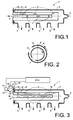
- the first and second distribution pipes 6, 8 are concentrically arranged with respect to each other, forming the interstitial gap 10 in between.
- an engine control unit is arranged to adapt the relative positions of the first pattern and the second pattern of flow distribution perforations 7, 9 for an optimal distribution of the recirculated exhaust gas depending on a given point of operation of the engine.
- the engine control unit (ECU) is arranged to adapt the relative positions of the first pattern and the second pattern of flow distribution perforations 7, 9 via a first rotating means 11 for rotating the first distribution pipe 6 and a second rotating means 12 for rotating the second distribution pipe 8.
- the first and second rotating means 11, 12 shown in the exemplifying embodiment includes electric servo motors 13 and 14 respectively.
- the servo motors 13, 14 are connected to pinion gears 15 and 16 that in turn rotate geared tuning discs 17 and 18 fixedly connected to the rotatable distribution pipes 6, 8 as schematically shown in Fig. 3 .
- the perforations 7, 9 in the distribution pipes 6, 8 are shaped as ovals, but they may alternatively be shaped as elongated slots as shown in the second embodiment in Fig. 3 .
- the invention also refers to an automotive vehicle (not shown) that has a tunable intake system 1 as described above.
Landscapes
- Engineering & Computer Science (AREA)
- Chemical & Material Sciences (AREA)
- Combustion & Propulsion (AREA)
- Mechanical Engineering (AREA)
- General Engineering & Computer Science (AREA)
- Exhaust-Gas Circulating Devices (AREA)
Abstract
- an exhaust gas recirculation manifold (2) arranged to distribute recirculated exhaust gas in an intake air stream to be introduced into the combustion engine;
- the manifold (2) having an exhaust gas recirculation inlet (3) and an intake air inlet (4) as well as at least one outlet (5) leading to the multiple cylinders of the engine;
- a first distribution pipe (6) connected to the exhaust gas recirculation inlet (3), said first distribution pipe (6) having a first pattern of flow distribution perforations (7) for distributing the recirculated exhaust gas into the manifold (2), where the invention is especially characterized in:
- a second distribution pipe (8) with a second pattern of flow distribution perforations (9) for distributing the recirculated exhaust gas into the manifold (2) is fitted outside of said first distribution pipe (6) whereby an interstitial gap (10) is formed therebetween, and
- at least one of said first and second distribution pipes (6, 8) being rotatable with respect to the other in order to selectively tune the distribution of recirculated exhaust gas for multiple operational points of the engine.
Description
- The invention relates to a tunable intake system for exhaust gas recirculation (EGR) in an internal combustion engine with a plurality of cylinders. The system comprises an exhaust gas recirculation manifold arranged to distribute recirculated exhaust gas in an intake air stream to be introduced into the combustion engine.
- Exhaust gas recirculation (EGR) systems are well known in the art per se and are used for controlling the generation of pollutant gases and particulate matter in internal combustion engines. EGR systems recirculate the exhaust gas into the intake air supply of the engine. The exhaust gas that is reintroduced into the engine reduces the concentration of oxygen in the intake air which reduces the maximum combustion temperature within the cylinders and slows down the chemical reaction of the combustion process, which reduces the formation of nitrous oxides.
- A problem with existing EGR systems is poor or less effective mixing and distribution of the exhaust gas and the fresh intake air. This causes problems with smoke and unwanted emissions. The use of EGR-distribution rails on modern vehicles improves the EGR-distribution but current systems are inherently hard or impossible to tune for multiple operational points of the internal combustion engine. This normally means that the distribution rail is optimized for one driving point or operational point only and that the engine control unit simply inactivates EGR-function in other operational points. Hence there is a need for EGR-systems that may easily tuned for optimum EGR-performance in multiple operational points of the engine.
- In order to alleviate the problem mentioned above it is an object of the invention to provide a tunable intake system for exhaust gas recirculation in an internal combustion engine with a plurality of cylinders, wherein the system comprises an exhaust gas recirculation manifold arranged to distribute recirculated exhaust gas in an intake air stream to be introduced into the combustion engine, where the manifold has an exhaust gas recirculation inlet and an intake air inlet as well as at least one outlet leading to the multiple cylinders of the engine. The manifold also has a first distribution pipe connected to the exhaust gas recirculation inlet, which first distribution pipe has a first pattern of flow distribution perforations for distributing the recirculated exhaust gas into the manifold. The invention is especially characterized in:
- a second distribution pipe with a second pattern of flow distribution perforations for distributing the recirculated exhaust gas into the manifold is fitted outside of said first distribution pipe whereby an interstitial gap is formed therebetween; and
- at least one of said first and second distribution pipes being rotatable with respect to the other in order to selectively tune the distribution of recirculated exhaust gas for multiple operational points of the engine.
- I an advantageous embodiment of the invention, the first and second distribution pipes are concentrically arranged and independently rotatable with respect to each other.
- In an advanced embodiment of the invention, an engine control unit (ECU) is arranged to adapt the relative positions of the first pattern and the second pattern of flow distribution perforations for an optimal distribution of the recirculated exhaust gas depending on a given point of operation of the engine. Preferably, the engine control unit, or ECUI, is arranged to adapt the relative positions of the first pattern and the second pattern of flow distribution perforations via a first rotating means for rotating the first distribution pipe and a second rotating means for rotating the second distribution pipe.
- In alternative embodiments of the invention, the perforations are shaped as ovals or as elongated slots.
- The invention also covers an automotive vehicle having a tunable intake system as described above.
- Further advantages and advantageous features of the invention are disclosed in the following description and in the dependent claims.
- With reference to the appended drawings, below follows a more detailed description of embodiments of the invention cited as examples.
- Fig. 1
- shows a simplified schematic overview of a tunable intake system for exhaust gas recirculation (EGR) according to a first exemplifying embodiment of the present invention.
- Fig. 2
- shows a schematic cross-sectional view of the concentrically arranged first and second distribution pipes which may be tuned by rotation with respect to each other.
- Fig. 3
- finally shows an alternative embodiment of the invention, in which an engine control unit (ECU) is arranged to adapt the relative positions of the first pattern and the second pattern of flow distribution perforations.
- The invention will now be described with reference to embodiments of the invention and with reference to the appended drawings. With initial reference to
Fig. 1 , this figure shows a schematic overview of a first exemplifying embodiment of atunable intake system 1 for exhaust gas recirculation (EGR) in an internal combustion engine with a plurality of cylinders. The engine and its cylinders are not shown in the drawings as the invention is focussed on theintake system 1 itself. - The
intake system 1 includes an exhaustgas recirculation manifold 2 which is arranged to distribute recirculated exhaust gas in an intake air stream to be introduced into the combustion engine. Themanifold 2 has an exhaustgas recirculation inlet 3 and an intake air inlet 4 as well as at least oneoutlet 5 leading to the multiple cylinders of the engine (not shown). Afirst distribution pipe 6 is connected to the exhaustgas recirculation inlet 3 and is provided with first pattern offlow distribution perforations 7 for distributing the recirculated exhaust gas into themanifold 2. Asecond distribution pipe 8 with a second pattern offlow distribution perforations 9 for distributing the recirculated exhaust gas into themanifold 2 is fitted outside of saidfirst distribution pipe 6 whereby aninterstitial gap 10 is formed therebetween. According to the invention at least one of said first andsecond distribution pipes - The first and
second distribution pipes distribution pipes distribution pipes - As shown in the cross-sectional view of
Fig. 2 , the first andsecond distribution pipes interstitial gap 10 in between. - In an alternative embodiment of the invention shown in
Fig. 3 , an engine control unit (ECU) is arranged to adapt the relative positions of the first pattern and the second pattern offlow distribution perforations flow distribution perforations first rotating means 11 for rotating thefirst distribution pipe 6 and asecond rotating means 12 for rotating thesecond distribution pipe 8. The first and second rotating means 11, 12 shown in the exemplifying embodiment includeselectric servo motors servo motors pinion gears tuning discs 17 and 18 fixedly connected to therotatable distribution pipes Fig. 3 . - In the exemplifying first embodiment shown in
Fig. 1 , theperforations distribution pipes Fig. 3 . - The invention also refers to an automotive vehicle (not shown) that has a
tunable intake system 1 as described above. - It is to be understood that the present invention is not limited to the embodiments described above and illustrated in the drawings and a skilled person will recognize that many changes and modifications may be made within the scope of the appended claims.
Claims (8)
- A tunable intake system (1) for exhaust gas recirculation in an internal combustion engine with a plurality of cylinders, the system comprising:- an exhaust gas recirculation manifold (2) arranged to distribute recirculated exhaust gas in an intake air stream to be introduced into the combustion engine;- the manifold (2) having an exhaust gas recirculation inlet (3) and an intake air inlet (4) as well as at least one outlet (5) leading to the multiple cylinders of the engine;- a first distribution pipe (6) connected to the exhaust gas recirculation inlet (3), said first distribution pipe (6) having a first pattern of flow distribution perforations (7) for distributing the recirculated exhaust gas into the manifold (2);
characterized in:- a second distribution pipe (8) with a second pattern of flow distribution perforations (9) for distributing the recirculated exhaust gas into the manifold (2) is fitted outside of said first distribution pipe (6) whereby an interstitial gap (10) is formed therebetween; and- at least one of said first and second distribution pipes (6, 8) being rotatable with respect to the other in order to selectively tune the distribution of recirculated exhaust gas for multiple operational points of the engine. - A tunable intake system (1) according to claim 1, wherein the first and second distribution pipes (6, 8) are independently rotatable with respect to each other.
- A tunable intake system (1) according to claim 1 or 2, wherein the first and second distribution pipes (6, 8) are concentrically arranged with respect to each other.
- A tunable intake system (1) according to any of the preceding claims, wherein an engine control unit (ECU) is arranged to adapt the relative positions of the first pattern and the second pattern of flow distribution perforations (7, 9) for an optimal distribution of the recirculated exhaust gas depending on a given point of operation of the engine.
- A tunable intake system (1) according to claim 4, wherein the engine control unit (ECU) is arranged to adapt the relative positions of the first pattern and the second pattern of flow distribution perforations (7, 9) via a first rotating means (11) for rotating the first distribution pipe (6) and a second rotating means (12) for rotating the second distribution pipe (8).
- A tunable intake system (1) according to any of the preceding claims, wherein the perforations (7, 9) are shaped as ovals.
- A tunable intake system (1) according to any of the preceding claims, wherein the perforations (7, 9) are shaped as elongated slots.
- An automotive vehicle having a tunable intake system (1) according to any of the preceding claims.
Priority Applications (3)
| Application Number | Priority Date | Filing Date | Title |
|---|---|---|---|
| EP15194885.8A EP3171013B1 (en) | 2015-11-17 | 2015-11-17 | Tunable intake system for exhaust gas recirculation in an internal combustion engine |
| US15/353,004 US10344716B2 (en) | 2015-11-17 | 2016-11-16 | Tunable intake system for exhaust gas recirculation in an internal combustion engine |
| CN201611272139.7A CN106870213B (en) | 2015-11-17 | 2016-11-17 | Adjustable intake system for exhaust gas recirculation of internal combustion engines |
Applications Claiming Priority (1)
| Application Number | Priority Date | Filing Date | Title |
|---|---|---|---|
| EP15194885.8A EP3171013B1 (en) | 2015-11-17 | 2015-11-17 | Tunable intake system for exhaust gas recirculation in an internal combustion engine |
Publications (2)
| Publication Number | Publication Date |
|---|---|
| EP3171013A1 true EP3171013A1 (en) | 2017-05-24 |
| EP3171013B1 EP3171013B1 (en) | 2019-08-14 |
Family
ID=54557309
Family Applications (1)
| Application Number | Title | Priority Date | Filing Date |
|---|---|---|---|
| EP15194885.8A Active EP3171013B1 (en) | 2015-11-17 | 2015-11-17 | Tunable intake system for exhaust gas recirculation in an internal combustion engine |
Country Status (3)
| Country | Link |
|---|---|
| US (1) | US10344716B2 (en) |
| EP (1) | EP3171013B1 (en) |
| CN (1) | CN106870213B (en) |
Families Citing this family (4)
| Publication number | Priority date | Publication date | Assignee | Title |
|---|---|---|---|---|
| JP6879068B2 (en) * | 2017-06-14 | 2021-06-02 | トヨタ紡織株式会社 | Intake manifold |
| DE102017212393A1 (en) | 2017-07-19 | 2019-01-24 | Mahle International Gmbh | Area-wise flexible exhaust gas recirculation line |
| CN108167091A (en) * | 2017-12-25 | 2018-06-15 | 潍柴动力股份有限公司 | Gas recirculation system mixing arrangement and automobile |
| US10227955B1 (en) * | 2018-03-02 | 2019-03-12 | GM Global Technology Operations LLC | System for exhaust gas recirculation |
Citations (6)
| Publication number | Priority date | Publication date | Assignee | Title |
|---|---|---|---|---|
| DE19631337A1 (en) * | 1996-08-02 | 1998-02-05 | Audi Ag | Exhaust gas recirculation system for internal combustion engine |
| JP3809696B2 (en) * | 1997-03-25 | 2006-08-16 | 株式会社豊田自動織機 | Exhaust gas recirculation device for internal combustion engine |
| FR2927373A1 (en) * | 2008-02-12 | 2009-08-14 | Renault Sas | Intake device for diesel engine of vehicle, has intake distributor including two separated plenum chambers that contain high and low pressure exhaust gas recirculation gases, respectively, and are connected to common intake pipe |
| FR2928704A1 (en) * | 2008-03-11 | 2009-09-18 | Peugeot Citroen Automobiles Sa | Air and exhaust gas intake distributing device for cylinder head of e.g. oil engine, of motor vehicle, has chamber with air and exhaust gas intake openings and chamber supplying openings that are selectively and partially closed by shutter |
| WO2009141212A1 (en) * | 2008-05-21 | 2009-11-26 | Pierburg Gmbh | Exhaust gas recirculation device for an internal combustion engine |
| EP2881576A1 (en) * | 2013-12-09 | 2015-06-10 | Valeo Systemes Thermiques | Recirculated exhaust gas distribution device and corresponding intake manifold and intake module |
Family Cites Families (11)
| Publication number | Priority date | Publication date | Assignee | Title |
|---|---|---|---|---|
| US615857A (en) * | 1898-12-13 | Stephen e | ||
| US4592545A (en) * | 1984-01-30 | 1986-06-03 | Sagedahl Steven M | Isokinetic exercise apparatus and method |
| JPH0615857B2 (en) * | 1984-06-29 | 1994-03-02 | マツダ株式会社 | Exhaust gas recirculation control device for engine |
| JPH0615857A (en) * | 1992-06-30 | 1994-01-25 | Nagano Japan Radio Co | Printer recording method |
| US5957116A (en) * | 1997-08-28 | 1999-09-28 | Cummins Engine Company, Inc. | Integrated and separable EGR distribution manifold |
| FR2768178B1 (en) * | 1997-09-11 | 1999-11-19 | Daniel Drecq | INTERNAL COMBUSTION ENGINE COMPRISING MEANS FOR RECIRCULATION OF EXHAUST AND SUPPLY GASES |
| FR2965306B1 (en) * | 2010-09-27 | 2012-09-14 | Valeo Systemes Thermiques | DEVICE FOR MIXING A RECIRCULATED INTAKE GAS FLOW AND A RECIRCULATED EXHAUST GAS FLOW COMPRISING RECIRCULATED EXHAUST GAS FLOW ISOLATION MEANS |
| CN203009103U (en) * | 2012-12-25 | 2013-06-19 | 重庆小康工业集团股份有限公司 | Exhaust gas distributing mechanism for exhaust gas recirculation system of diesel engine |
| FR3007470B1 (en) * | 2013-06-25 | 2017-08-11 | Valeo Systemes De Controle Moteur | DISTRIBUTION MODULE FOR DISTRIBUTING A MIXTURE OF ADMISSION |
| CN204126779U (en) * | 2014-10-14 | 2015-01-28 | 潍坊力创电子科技有限公司 | Bushing type air-intake of combustion engine mechanism |
| US9771902B2 (en) * | 2014-12-05 | 2017-09-26 | Denso International America, Inc. | EGR device having rotary valve |
-
2015
- 2015-11-17 EP EP15194885.8A patent/EP3171013B1/en active Active
-
2016
- 2016-11-16 US US15/353,004 patent/US10344716B2/en active Active
- 2016-11-17 CN CN201611272139.7A patent/CN106870213B/en active Active
Patent Citations (6)
| Publication number | Priority date | Publication date | Assignee | Title |
|---|---|---|---|---|
| DE19631337A1 (en) * | 1996-08-02 | 1998-02-05 | Audi Ag | Exhaust gas recirculation system for internal combustion engine |
| JP3809696B2 (en) * | 1997-03-25 | 2006-08-16 | 株式会社豊田自動織機 | Exhaust gas recirculation device for internal combustion engine |
| FR2927373A1 (en) * | 2008-02-12 | 2009-08-14 | Renault Sas | Intake device for diesel engine of vehicle, has intake distributor including two separated plenum chambers that contain high and low pressure exhaust gas recirculation gases, respectively, and are connected to common intake pipe |
| FR2928704A1 (en) * | 2008-03-11 | 2009-09-18 | Peugeot Citroen Automobiles Sa | Air and exhaust gas intake distributing device for cylinder head of e.g. oil engine, of motor vehicle, has chamber with air and exhaust gas intake openings and chamber supplying openings that are selectively and partially closed by shutter |
| WO2009141212A1 (en) * | 2008-05-21 | 2009-11-26 | Pierburg Gmbh | Exhaust gas recirculation device for an internal combustion engine |
| EP2881576A1 (en) * | 2013-12-09 | 2015-06-10 | Valeo Systemes Thermiques | Recirculated exhaust gas distribution device and corresponding intake manifold and intake module |
Also Published As
| Publication number | Publication date |
|---|---|
| US10344716B2 (en) | 2019-07-09 |
| CN106870213B (en) | 2020-04-21 |
| EP3171013B1 (en) | 2019-08-14 |
| CN106870213A (en) | 2017-06-20 |
| US20170138318A1 (en) | 2017-05-18 |
Similar Documents
| Publication | Publication Date | Title |
|---|---|---|
| US10344716B2 (en) | Tunable intake system for exhaust gas recirculation in an internal combustion engine | |
| EP3111067B1 (en) | Exhaust treatment system and method for treatment of an exhaust stream | |
| DE69719443T2 (en) | Method of controlling the intake of a four-stroke direct injection engine | |
| US11007481B2 (en) | Exhaust treatment system and method for treatment of an exhaust gas stream | |
| DE102017130695A1 (en) | A method for exhaust aftertreatment of an internal combustion engine in a hybrid vehicle and hybrid vehicle with an exhaust aftertreatment system | |
| DE102008054341A1 (en) | Method and system for determining the efficiency of a diesel oxidation catalyst | |
| DE102010005831A1 (en) | Exhaust line for an internal combustion engine and method for operating an internal combustion engine | |
| CN106437949B (en) | A kind of syndrome exhaust gas cleaner suitable for High-Powered Vehicle | |
| EP3404228A1 (en) | Regeneration of a particle filter or four-way catalytic converter in the exhaust system of a combustion engine | |
| DE102013205575A1 (en) | EXHAUST GAS TREATMENT AND EXHAUST GAS RECYCLING SYSTEMS | |
| US9512762B2 (en) | Internal combustion engine having dedicated cylinder(s) for generation of both EGR and exhaust aftertreatment reductant for NOx-reducing catalyst | |
| DE102021201451A1 (en) | DOUBLE ELEMENT ENGINE GAS VALVE | |
| CN110617151A (en) | Comprehensive treatment device and method for exhaust pollutants of diesel vehicle | |
| DE102018103230A1 (en) | Exhaust gas aftertreatment system and method for exhaust aftertreatment of an internal combustion engine | |
| US10774737B2 (en) | Cleaning installation for an internal combustion engine | |
| DE102015216851A1 (en) | Motor vehicle with exhaust gas recirculation | |
| DE102015216730A1 (en) | Motor vehicle with exhaust gas recirculation | |
| US20100037872A1 (en) | Preventing egr system soot contamination | |
| JP2007255303A (en) | CONTROL APPARATUS OF ENGINE WITH SELECTIVE REDUCTION TYPE NOx CATALYST | |
| CN110630391A (en) | Comprehensive treatment device and treatment method for tail gas of diesel vehicle | |
| EP3601759A1 (en) | Method and system for control of at least one of a dosage device and an engine | |
| US20160341137A1 (en) | Apparatus for controlling engine of vehicle and method thereof | |
| DE102016007208A1 (en) | Method and system for controlling exhaust gases resulting from combustion | |
| DE102017212628A1 (en) | A method for regenerating an exhaust aftertreatment device of a device and motor vehicle |
Legal Events
| Date | Code | Title | Description |
|---|---|---|---|
| PUAI | Public reference made under article 153(3) epc to a published international application that has entered the european phase |
Free format text: ORIGINAL CODE: 0009012 |
|
| STAA | Information on the status of an ep patent application or granted ep patent |
Free format text: STATUS: THE APPLICATION HAS BEEN PUBLISHED |
|
| AK | Designated contracting states |
Kind code of ref document: A1 Designated state(s): AL AT BE BG CH CY CZ DE DK EE ES FI FR GB GR HR HU IE IS IT LI LT LU LV MC MK MT NL NO PL PT RO RS SE SI SK SM TR |
|
| AX | Request for extension of the european patent |
Extension state: BA ME |
|
| STAA | Information on the status of an ep patent application or granted ep patent |
Free format text: STATUS: REQUEST FOR EXAMINATION WAS MADE |
|
| 17P | Request for examination filed |
Effective date: 20171124 |
|
| RBV | Designated contracting states (corrected) |
Designated state(s): AL AT BE BG CH CY CZ DE DK EE ES FI FR GB GR HR HU IE IS IT LI LT LU LV MC MK MT NL NO PL PT RO RS SE SI SK SM TR |
|
| STAA | Information on the status of an ep patent application or granted ep patent |
Free format text: STATUS: EXAMINATION IS IN PROGRESS |
|
| 17Q | First examination report despatched |
Effective date: 20180226 |
|
| GRAP | Despatch of communication of intention to grant a patent |
Free format text: ORIGINAL CODE: EPIDOSNIGR1 |
|
| STAA | Information on the status of an ep patent application or granted ep patent |
Free format text: STATUS: GRANT OF PATENT IS INTENDED |
|
| RIC1 | Information provided on ipc code assigned before grant |
Ipc: F02M 26/19 20160101ALI20190219BHEP Ipc: F02M 26/42 20160101ALI20190219BHEP Ipc: F02M 26/00 20160101ALN20190219BHEP Ipc: F02M 35/10 20060101AFI20190219BHEP Ipc: F02M 26/17 20160101ALI20190219BHEP |
|
| INTG | Intention to grant announced |
Effective date: 20190322 |
|
| GRAS | Grant fee paid |
Free format text: ORIGINAL CODE: EPIDOSNIGR3 |
|
| GRAA | (expected) grant |
Free format text: ORIGINAL CODE: 0009210 |
|
| STAA | Information on the status of an ep patent application or granted ep patent |
Free format text: STATUS: THE PATENT HAS BEEN GRANTED |
|
| AK | Designated contracting states |
Kind code of ref document: B1 Designated state(s): AL AT BE BG CH CY CZ DE DK EE ES FI FR GB GR HR HU IE IS IT LI LT LU LV MC MK MT NL NO PL PT RO RS SE SI SK SM TR |
|
| REG | Reference to a national code |
Ref country code: GB Ref legal event code: FG4D |
|
| REG | Reference to a national code |
Ref country code: CH Ref legal event code: EP Ref country code: AT Ref legal event code: REF Ref document number: 1167321 Country of ref document: AT Kind code of ref document: T Effective date: 20190815 |
|
| REG | Reference to a national code |
Ref country code: IE Ref legal event code: FG4D |
|
| REG | Reference to a national code |
Ref country code: DE Ref legal event code: R096 Ref document number: 602015035730 Country of ref document: DE |
|
| REG | Reference to a national code |
Ref country code: NL Ref legal event code: MP Effective date: 20190814 |
|
| REG | Reference to a national code |
Ref country code: LT Ref legal event code: MG4D |
|
| PG25 | Lapsed in a contracting state [announced via postgrant information from national office to epo] |
Ref country code: LT Free format text: LAPSE BECAUSE OF FAILURE TO SUBMIT A TRANSLATION OF THE DESCRIPTION OR TO PAY THE FEE WITHIN THE PRESCRIBED TIME-LIMIT Effective date: 20190814 Ref country code: NL Free format text: LAPSE BECAUSE OF FAILURE TO SUBMIT A TRANSLATION OF THE DESCRIPTION OR TO PAY THE FEE WITHIN THE PRESCRIBED TIME-LIMIT Effective date: 20190814 Ref country code: NO Free format text: LAPSE BECAUSE OF FAILURE TO SUBMIT A TRANSLATION OF THE DESCRIPTION OR TO PAY THE FEE WITHIN THE PRESCRIBED TIME-LIMIT Effective date: 20191114 Ref country code: BG Free format text: LAPSE BECAUSE OF FAILURE TO SUBMIT A TRANSLATION OF THE DESCRIPTION OR TO PAY THE FEE WITHIN THE PRESCRIBED TIME-LIMIT Effective date: 20191114 Ref country code: SE Free format text: LAPSE BECAUSE OF FAILURE TO SUBMIT A TRANSLATION OF THE DESCRIPTION OR TO PAY THE FEE WITHIN THE PRESCRIBED TIME-LIMIT Effective date: 20190814 Ref country code: PT Free format text: LAPSE BECAUSE OF FAILURE TO SUBMIT A TRANSLATION OF THE DESCRIPTION OR TO PAY THE FEE WITHIN THE PRESCRIBED TIME-LIMIT Effective date: 20191216 Ref country code: HR Free format text: LAPSE BECAUSE OF FAILURE TO SUBMIT A TRANSLATION OF THE DESCRIPTION OR TO PAY THE FEE WITHIN THE PRESCRIBED TIME-LIMIT Effective date: 20190814 Ref country code: FI Free format text: LAPSE BECAUSE OF FAILURE TO SUBMIT A TRANSLATION OF THE DESCRIPTION OR TO PAY THE FEE WITHIN THE PRESCRIBED TIME-LIMIT Effective date: 20190814 |
|
| REG | Reference to a national code |
Ref country code: AT Ref legal event code: MK05 Ref document number: 1167321 Country of ref document: AT Kind code of ref document: T Effective date: 20190814 |
|
| PG25 | Lapsed in a contracting state [announced via postgrant information from national office to epo] |
Ref country code: IS Free format text: LAPSE BECAUSE OF FAILURE TO SUBMIT A TRANSLATION OF THE DESCRIPTION OR TO PAY THE FEE WITHIN THE PRESCRIBED TIME-LIMIT Effective date: 20191214 Ref country code: GR Free format text: LAPSE BECAUSE OF FAILURE TO SUBMIT A TRANSLATION OF THE DESCRIPTION OR TO PAY THE FEE WITHIN THE PRESCRIBED TIME-LIMIT Effective date: 20191115 Ref country code: ES Free format text: LAPSE BECAUSE OF FAILURE TO SUBMIT A TRANSLATION OF THE DESCRIPTION OR TO PAY THE FEE WITHIN THE PRESCRIBED TIME-LIMIT Effective date: 20190814 Ref country code: RS Free format text: LAPSE BECAUSE OF FAILURE TO SUBMIT A TRANSLATION OF THE DESCRIPTION OR TO PAY THE FEE WITHIN THE PRESCRIBED TIME-LIMIT Effective date: 20190814 Ref country code: AL Free format text: LAPSE BECAUSE OF FAILURE TO SUBMIT A TRANSLATION OF THE DESCRIPTION OR TO PAY THE FEE WITHIN THE PRESCRIBED TIME-LIMIT Effective date: 20190814 Ref country code: LV Free format text: LAPSE BECAUSE OF FAILURE TO SUBMIT A TRANSLATION OF THE DESCRIPTION OR TO PAY THE FEE WITHIN THE PRESCRIBED TIME-LIMIT Effective date: 20190814 |
|
| PG25 | Lapsed in a contracting state [announced via postgrant information from national office to epo] |
Ref country code: TR Free format text: LAPSE BECAUSE OF FAILURE TO SUBMIT A TRANSLATION OF THE DESCRIPTION OR TO PAY THE FEE WITHIN THE PRESCRIBED TIME-LIMIT Effective date: 20190814 |
|
| PG25 | Lapsed in a contracting state [announced via postgrant information from national office to epo] |
Ref country code: RO Free format text: LAPSE BECAUSE OF FAILURE TO SUBMIT A TRANSLATION OF THE DESCRIPTION OR TO PAY THE FEE WITHIN THE PRESCRIBED TIME-LIMIT Effective date: 20190814 Ref country code: DK Free format text: LAPSE BECAUSE OF FAILURE TO SUBMIT A TRANSLATION OF THE DESCRIPTION OR TO PAY THE FEE WITHIN THE PRESCRIBED TIME-LIMIT Effective date: 20190814 Ref country code: AT Free format text: LAPSE BECAUSE OF FAILURE TO SUBMIT A TRANSLATION OF THE DESCRIPTION OR TO PAY THE FEE WITHIN THE PRESCRIBED TIME-LIMIT Effective date: 20190814 Ref country code: EE Free format text: LAPSE BECAUSE OF FAILURE TO SUBMIT A TRANSLATION OF THE DESCRIPTION OR TO PAY THE FEE WITHIN THE PRESCRIBED TIME-LIMIT Effective date: 20190814 Ref country code: PL Free format text: LAPSE BECAUSE OF FAILURE TO SUBMIT A TRANSLATION OF THE DESCRIPTION OR TO PAY THE FEE WITHIN THE PRESCRIBED TIME-LIMIT Effective date: 20190814 |
|
| PG25 | Lapsed in a contracting state [announced via postgrant information from national office to epo] |
Ref country code: SK Free format text: LAPSE BECAUSE OF FAILURE TO SUBMIT A TRANSLATION OF THE DESCRIPTION OR TO PAY THE FEE WITHIN THE PRESCRIBED TIME-LIMIT Effective date: 20190814 Ref country code: CZ Free format text: LAPSE BECAUSE OF FAILURE TO SUBMIT A TRANSLATION OF THE DESCRIPTION OR TO PAY THE FEE WITHIN THE PRESCRIBED TIME-LIMIT Effective date: 20190814 Ref country code: IS Free format text: LAPSE BECAUSE OF FAILURE TO SUBMIT A TRANSLATION OF THE DESCRIPTION OR TO PAY THE FEE WITHIN THE PRESCRIBED TIME-LIMIT Effective date: 20200224 Ref country code: SM Free format text: LAPSE BECAUSE OF FAILURE TO SUBMIT A TRANSLATION OF THE DESCRIPTION OR TO PAY THE FEE WITHIN THE PRESCRIBED TIME-LIMIT Effective date: 20190814 |
|
| REG | Reference to a national code |
Ref country code: DE Ref legal event code: R097 Ref document number: 602015035730 Country of ref document: DE |
|
| REG | Reference to a national code |
Ref country code: CH Ref legal event code: PL |
|
| PLBE | No opposition filed within time limit |
Free format text: ORIGINAL CODE: 0009261 |
|
| STAA | Information on the status of an ep patent application or granted ep patent |
Free format text: STATUS: NO OPPOSITION FILED WITHIN TIME LIMIT |
|
| PG2D | Information on lapse in contracting state deleted |
Ref country code: IS |
|
| PG25 | Lapsed in a contracting state [announced via postgrant information from national office to epo] |
Ref country code: MC Free format text: LAPSE BECAUSE OF FAILURE TO SUBMIT A TRANSLATION OF THE DESCRIPTION OR TO PAY THE FEE WITHIN THE PRESCRIBED TIME-LIMIT Effective date: 20190814 Ref country code: CH Free format text: LAPSE BECAUSE OF NON-PAYMENT OF DUE FEES Effective date: 20191130 Ref country code: LU Free format text: LAPSE BECAUSE OF NON-PAYMENT OF DUE FEES Effective date: 20191117 Ref country code: LI Free format text: LAPSE BECAUSE OF NON-PAYMENT OF DUE FEES Effective date: 20191130 |
|
| 26N | No opposition filed |
Effective date: 20200603 |
|
| REG | Reference to a national code |
Ref country code: BE Ref legal event code: MM Effective date: 20191130 |
|
| PG25 | Lapsed in a contracting state [announced via postgrant information from national office to epo] |
Ref country code: SI Free format text: LAPSE BECAUSE OF FAILURE TO SUBMIT A TRANSLATION OF THE DESCRIPTION OR TO PAY THE FEE WITHIN THE PRESCRIBED TIME-LIMIT Effective date: 20190814 |
|
| GBPC | Gb: european patent ceased through non-payment of renewal fee |
Effective date: 20191117 |
|
| PG25 | Lapsed in a contracting state [announced via postgrant information from national office to epo] |
Ref country code: IE Free format text: LAPSE BECAUSE OF NON-PAYMENT OF DUE FEES Effective date: 20191117 Ref country code: GB Free format text: LAPSE BECAUSE OF NON-PAYMENT OF DUE FEES Effective date: 20191117 |
|
| PG25 | Lapsed in a contracting state [announced via postgrant information from national office to epo] |
Ref country code: BE Free format text: LAPSE BECAUSE OF NON-PAYMENT OF DUE FEES Effective date: 20191130 |
|
| PG25 | Lapsed in a contracting state [announced via postgrant information from national office to epo] |
Ref country code: CY Free format text: LAPSE BECAUSE OF FAILURE TO SUBMIT A TRANSLATION OF THE DESCRIPTION OR TO PAY THE FEE WITHIN THE PRESCRIBED TIME-LIMIT Effective date: 20190814 |
|
| PG25 | Lapsed in a contracting state [announced via postgrant information from national office to epo] |
Ref country code: HU Free format text: LAPSE BECAUSE OF FAILURE TO SUBMIT A TRANSLATION OF THE DESCRIPTION OR TO PAY THE FEE WITHIN THE PRESCRIBED TIME-LIMIT; INVALID AB INITIO Effective date: 20151117 Ref country code: MT Free format text: LAPSE BECAUSE OF FAILURE TO SUBMIT A TRANSLATION OF THE DESCRIPTION OR TO PAY THE FEE WITHIN THE PRESCRIBED TIME-LIMIT Effective date: 20190814 |
|
| PG25 | Lapsed in a contracting state [announced via postgrant information from national office to epo] |
Ref country code: MK Free format text: LAPSE BECAUSE OF FAILURE TO SUBMIT A TRANSLATION OF THE DESCRIPTION OR TO PAY THE FEE WITHIN THE PRESCRIBED TIME-LIMIT Effective date: 20190814 |
|
| P01 | Opt-out of the competence of the unified patent court (upc) registered |
Effective date: 20231212 |
|
| PGFP | Annual fee paid to national office [announced via postgrant information from national office to epo] |
Ref country code: DE Payment date: 20241022 Year of fee payment: 10 |
|
| PGFP | Annual fee paid to national office [announced via postgrant information from national office to epo] |
Ref country code: FR Payment date: 20241022 Year of fee payment: 10 |
|
| PGFP | Annual fee paid to national office [announced via postgrant information from national office to epo] |
Ref country code: IT Payment date: 20241022 Year of fee payment: 10 |