EP3171001A1 - Variable compression ratio internal combustion engine - Google Patents
Variable compression ratio internal combustion engine Download PDFInfo
- Publication number
- EP3171001A1 EP3171001A1 EP14897570.9A EP14897570A EP3171001A1 EP 3171001 A1 EP3171001 A1 EP 3171001A1 EP 14897570 A EP14897570 A EP 14897570A EP 3171001 A1 EP3171001 A1 EP 3171001A1
- Authority
- EP
- European Patent Office
- Prior art keywords
- compression ratio
- shaft
- rotation
- control shaft
- rotation shaft
- Prior art date
- Legal status (The legal status is an assumption and is not a legal conclusion. Google has not performed a legal analysis and makes no representation as to the accuracy of the status listed.)
- Granted
Links
- 230000006835 compression Effects 0.000 title claims abstract description 143
- 238000007906 compression Methods 0.000 title claims abstract description 143
- 238000002485 combustion reaction Methods 0.000 title claims abstract description 27
- 230000033228 biological regulation Effects 0.000 claims abstract description 36
- 230000001105 regulatory effect Effects 0.000 claims abstract description 28
- 230000007246 mechanism Effects 0.000 claims abstract description 23
- 238000001514 detection method Methods 0.000 claims description 12
- 230000001276 controlling effect Effects 0.000 description 4
- 230000009467 reduction Effects 0.000 description 4
- 238000005299 abrasion Methods 0.000 description 2
- 230000008859 change Effects 0.000 description 2
- 239000003638 chemical reducing agent Substances 0.000 description 2
- 230000007423 decrease Effects 0.000 description 2
- 230000006866 deterioration Effects 0.000 description 2
- 238000010586 diagram Methods 0.000 description 2
- 230000000694 effects Effects 0.000 description 2
- 239000000446 fuel Substances 0.000 description 1
- 238000004519 manufacturing process Methods 0.000 description 1
- 238000000034 method Methods 0.000 description 1
- 239000000203 mixture Substances 0.000 description 1
- 230000008569 process Effects 0.000 description 1
- 238000004904 shortening Methods 0.000 description 1
- 230000001629 suppression Effects 0.000 description 1
Images

Classifications
-
- F—MECHANICAL ENGINEERING; LIGHTING; HEATING; WEAPONS; BLASTING
- F02—COMBUSTION ENGINES; HOT-GAS OR COMBUSTION-PRODUCT ENGINE PLANTS
- F02B—INTERNAL-COMBUSTION PISTON ENGINES; COMBUSTION ENGINES IN GENERAL
- F02B75/00—Other engines
- F02B75/04—Engines with variable distances between pistons at top dead-centre positions and cylinder heads
-
- F—MECHANICAL ENGINEERING; LIGHTING; HEATING; WEAPONS; BLASTING
- F02—COMBUSTION ENGINES; HOT-GAS OR COMBUSTION-PRODUCT ENGINE PLANTS
- F02B—INTERNAL-COMBUSTION PISTON ENGINES; COMBUSTION ENGINES IN GENERAL
- F02B75/00—Other engines
- F02B75/32—Engines characterised by connections between pistons and main shafts and not specific to preceding main groups
-
- F—MECHANICAL ENGINEERING; LIGHTING; HEATING; WEAPONS; BLASTING
- F02—COMBUSTION ENGINES; HOT-GAS OR COMBUSTION-PRODUCT ENGINE PLANTS
- F02D—CONTROLLING COMBUSTION ENGINES
- F02D15/00—Varying compression ratio
- F02D15/02—Varying compression ratio by alteration or displacement of piston stroke
-
- F—MECHANICAL ENGINEERING; LIGHTING; HEATING; WEAPONS; BLASTING
- F02—COMBUSTION ENGINES; HOT-GAS OR COMBUSTION-PRODUCT ENGINE PLANTS
- F02B—INTERNAL-COMBUSTION PISTON ENGINES; COMBUSTION ENGINES IN GENERAL
- F02B75/00—Other engines
- F02B75/04—Engines with variable distances between pistons at top dead-centre positions and cylinder heads
- F02B75/045—Engines with variable distances between pistons at top dead-centre positions and cylinder heads by means of a variable connecting rod length
Definitions
- the present invention relates to a control device for a variable compression ratio internal combustion engine provided with a variable compression ratio mechanism capable of changing an engine compression ratio in accordance with a rotational position of a control shaft.
- Patent document 1 discloses an internal combustion engine (hereinafter referred to as "variable compression ratio internal combustion engine") provided with a variable compression ratio mechanism capable of changing an engine compression ratio in accordance with a rotational position of a control shaft.
- a speed reducing mechanism is provided between the control shaft and an actuator such as a motor that drives the control shaft.
- a rotation shaft which is linked through a lever to the control shaft, is provided in the speed reducing mechanism.
- the rotation shaft is rotatably supported in a housing fixed to an engine body.
- Patent document 1 Japanese Patent Provisional Publication No. JP2013-253512
- a high compression ratio side regulation part and a low compression ratio side regulation part are provided in the housing that rotatably supports the rotation shaft, for mechanically regulating a rotatable range of the rotation shaft between a high compression ratio side and a low compression ratio side.
- compression ratio reference position learning operation is carried out, based on a detection signal from a rotation sensor that detects a rotational position of the rotation shaft, in a state where the rotational position of the rotation shaft has been regulated and positioned mechanically by means of either of these two regulation parts.
- the regulation parts and the rotation sensor are provided in the same housing, and thus there is a possibility that the detection accuracy of the rotation sensor deteriorates owing to vibrations, deformation and the like, occurring when the control shaft is brought into collision with a stopper face of each of the regulation parts, thus resulting in a deterioration in the compression ratio reference position learning accuracy.
- an object of the present invention to improve the compression ratio reference position learning accuracy in a variable compression ratio internal combustion engine provided with a variable compression ratio mechanism.
- a variable compression ratio internal combustion engine of the present invention includes a control shaft rotatably supported by an engine body, a variable compression ratio mechanism for changing an engine compression ratio in accordance with a rotational position of the control shaft, an actuator that rotatively drives the control shaft, and a speed reducing mechanism for reducing a rotational power of the actuator and for transmitting the speed-reduced power to the control shaft.
- the speed reducing mechanism has a rotation shaft rotatably supported in a housing fixed to the engine body and a lever that connects the rotation shaft and the control shaft.
- variable compression ratio internal combustion engine has a first regulation part located in the engine body for mechanically regulating the control shaft to a position of maximum rotation on one side of a low compression ratio side and a high compression ratio side and a second regulation part located in the housing for mechanically regulating the rotation shaft to a position of maximum rotation on the other side of the low compression ratio side and the high compression ratio side.
- the first regulation part is configured to regulate the control shaft to the position of maximum rotation on the high compression ratio side
- the second regulation part is configured to regulate the rotation shaft to the position of maximum rotation on the low compression ratio side.
- variable compression ratio internal combustion engine has a rotation sensor for detecting a rotational position of one shaft of the control shaft and the rotation shaft, and a reference position learning means for carrying out compression ratio reference position learning operation, based on a detection signal from the rotation sensor, in a state where the other shaft of the control shaft and the rotation shaft has been mechanically regulated by either the first regulation part or the second regulation part.
- the first regulation part and the second regulation part are located individually on the engine body side where the control shaft is installed and on the housing side where the rotation shaft is installed, for regulating a rotatable range of the compression ratio.
- the degree of freedom in layout is high. For instance when carrying out compression ratio reference position learning operation through the use of the rotation sensor, it is possible to suppress a deterioration in the detection accuracy of the rotation sensor by bringing either the control shaft or the rotation shaft into a mechanically-regulated state by means of the regulation part not provided with the rotation sensor, thus improving the compression ratio reference position learning accuracy.
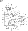
- FIGS. 1 to 3 is a control device for a variable compression ratio internal combustion engine 1 provided with a variable compression ratio mechanism 10 in one embodiment according to the present invention.
- variable compression ratio internal combustion engine 1 is mainly constructed by a cylinder block 2 serving as an engine body and a cylinder head 3 fixed onto the cylinder block 2.
- a piston 5 is liftably (slidably) fitted into a cylinder 4 of the cylinder head 3.
- Variable compression ratio mechanism 10 has a lower link 11, an upper link 12, a control shaft 13, and a control link 14.
- the lower link is rotatably installed on a crankpin 7 of a crankshaft 6.
- the upper link is configured to connect the lower link 11 and the piston 5.
- the control shaft is rotatably supported on the cylinder block 2.
- the control link is configured to connect the control shaft 13 and the lower link 11.
- the upper end of upper link 12 and the piston 5 are connected to each other by means of a piston pin 15 so as to permit relative rotation between them.
- Upper link 12 and lower link 11 are connected to each other by means of a first connecting pin 16 so as to permit relative rotation between them.
- Lower link 11 and the upper end of control link 14 are connected to each other by means of a second connecting pin 17 so as to permit relative rotation between them.
- the lower end of lower link 11 is rotatably installed on a control eccentric shaft 18 provided eccentrically to a journal portion 13A serving as the rotation center of control shaft 13.
- a speed reducing mechanism 22 is interposed in a power-transmission path between the control shaft 13 and an output shaft 21A of a motor 21, serving as an actuator that rotatively drives the control shaft 13, for reducing a rotational power of the output shaft 21A of motor 21 and for transmitting the speed-reduced power to the control shaft 13.
- Speed reducing mechanism 22 has a speed reducer 23 such as a wave motion gear device that provides high reduction ratios, a rotation shaft 24 that rotates integrally with the output shaft of speed reducer 23, and a lever 25 configured to connect the rotation shaft 24 and the control shaft 13 (see FIG. 1 ).
- Rotation shaft 24 is accommodated and arranged inside of a housing 26 fixedly connected to and located alongside the cylinder block 2.
- the rotation shaft is rotatably supported inside of the housing 26 and arranged parallel to the control shaft 13.
- Lever 25 is structured to extend through slits of cylinder block 2 and housing 26.
- lever 25 and the top end of a first arm 27 extending radially from the journal portion 13A of control shaft 13 are connected to each other by means of a third connecting pin 28 so as to permit relative rotation between them.
- the other end of lever 25 and the top end of a second arm 29 extending radially from a journal portion 24A serving as the rotation center of rotation shaft 24 are connected to each other by means of a fourth connecting pin 30 so as to permit relative rotation between them.
- variable compression ratio mechanism 10 constructed as discussed above, when the rotational position of control shaft 13 is changed by means of the motor 21 through the speed reducing mechanism 22, a change in the attitude of lower link 11 occurs and thus a change in stroke characteristic of piston 5 including a piston top dead center (TDC) position and a piston bottom dead center (BDC) position occurs. In this manner, an engine compression ratio is continuously changed.
- TDC piston top dead center
- BDC piston bottom dead center
- a rotation sensor 31 is installed on the housing 26 for detecting a rotational position of rotation shaft 24 corresponding to the actual compression ratio, that is, a compression ratio reference position.
- a motor speed detection sensor 32 is installed on the motor 21 for detecting a motor speed.
- a control unit 33 is a digital computer system capable of storing and executing various control processes.
- the control unit is configured to output control signals to various actuators based on an engine operating condition detected by sensors 31, 32 and the like, for integrally controlling respective operations of these actuators.
- the control unit is configured to control driving of a variable valve timing mechanism 34 capable of changing intake valve timing (or exhaust valve timing), for controlling intake valve open timing (IVO) and intake valve closure timing (IVC).
- the control unit is configured to control driving of a spark plug 35 that spark-ignites an air-fuel mixture in the combustion chamber, for controlling ignition timing.
- the control unit is configured to control driving of an electronically-controlled throttle 36 that opens or closes an intake-air passage, for controlling throttle opening.
- control unit 33 is configured to set a target compression ratio based on the engine operating condition, and feedback-control the operation of motor 21 for maintaining the deviation between the target compression ratio and the actual compression ratio detected by the rotation sensor 31 as small as possible.
- a rotatable range of each of control shaft 13 and rotation shaft 24, both linked together in a manner so as to rotate in conjunction with each other, is mechanically regulated or limited by means of a low compression ratio side stopper face 41 serving as a low compression ratio side regulation part and a high compression ratio side stopper face 42 serving as a high compression ratio side regulation part.
- the low compression ratio side stopper face 41 is provided inside of the housing 26.
- control shaft 13 and rotation shaft 24 are structured to be mechanically locked up and regulated at a low compression ratio side stopper position.
- the high compression ratio side stopper face 42 is provided inside of the cylinder block 2.
- control shaft 13 rotates toward a maximum high compression ratio side i.e., in the direction indicated by the arrow "Y2" in FIG. 1
- a side face of the first arm 27 is brought into abutted-engagement with the high compression ratio side stopper face 42.
- control shaft 13 and rotation shaft 24 are also structured to be mechanically locked up and regulated at a high compression ratio side stopper position.
- the initializing operation is carried out.
- this initializing operation for instance in a state where, with the rotation shaft 24 in abutted-engagement with the high compression ratio side stopper face 42, control shaft 13 has been mechanically regulated and locked up at the high compression ratio side stopper position serving as a reference position, a detected value of rotation sensor 31, corresponding to an actual compression ratio, is learned and initialized to a given initial value corresponding to the compression ratio reference position.
Abstract
Description
- The present invention relates to a control device for a variable compression ratio internal combustion engine provided with a variable compression ratio mechanism capable of changing an engine compression ratio in accordance with a rotational position of a control shaft.
-
Patent document 1 discloses an internal combustion engine (hereinafter referred to as "variable compression ratio internal combustion engine") provided with a variable compression ratio mechanism capable of changing an engine compression ratio in accordance with a rotational position of a control shaft. A speed reducing mechanism is provided between the control shaft and an actuator such as a motor that drives the control shaft. A rotation shaft, which is linked through a lever to the control shaft, is provided in the speed reducing mechanism. For example, the rotation shaft is rotatably supported in a housing fixed to an engine body. - Patent document 1: Japanese Patent Provisional Publication No.
JP2013-253512 - In such a variable compression ratio internal combustion engine, a high compression ratio side regulation part and a low compression ratio side regulation part are provided in the housing that rotatably supports the rotation shaft, for mechanically regulating a rotatable range of the rotation shaft between a high compression ratio side and a low compression ratio side. Also, compression ratio reference position learning operation is carried out, based on a detection signal from a rotation sensor that detects a rotational position of the rotation shaft, in a state where the rotational position of the rotation shaft has been regulated and positioned mechanically by means of either of these two regulation parts.
- However, the regulation parts and the rotation sensor are provided in the same housing, and thus there is a possibility that the detection accuracy of the rotation sensor deteriorates owing to vibrations, deformation and the like, occurring when the control shaft is brought into collision with a stopper face of each of the regulation parts, thus resulting in a deterioration in the compression ratio reference position learning accuracy.
- It is, therefore, in view of the previously-described circumstances, an object of the present invention to improve the compression ratio reference position learning accuracy in a variable compression ratio internal combustion engine provided with a variable compression ratio mechanism.
- A variable compression ratio internal combustion engine of the present invention includes a control shaft rotatably supported by an engine body, a variable compression ratio mechanism for changing an engine compression ratio in accordance with a rotational position of the control shaft, an actuator that rotatively drives the control shaft, and a speed reducing mechanism for reducing a rotational power of the actuator and for transmitting the speed-reduced power to the control shaft. The speed reducing mechanism has a rotation shaft rotatably supported in a housing fixed to the engine body and a lever that connects the rotation shaft and the control shaft.
- The variable compression ratio internal combustion engine has a first regulation part located in the engine body for mechanically regulating the control shaft to a position of maximum rotation on one side of a low compression ratio side and a high compression ratio side and a second regulation part located in the housing for mechanically regulating the rotation shaft to a position of maximum rotation on the other side of the low compression ratio side and the high compression ratio side.
- The first regulation part is configured to regulate the control shaft to the position of maximum rotation on the high compression ratio side, whereas the second regulation part is configured to regulate the rotation shaft to the position of maximum rotation on the low compression ratio side.
- Preferably, the variable compression ratio internal combustion engine has a rotation sensor for detecting a rotational position of one shaft of the control shaft and the rotation shaft, and a reference position learning means for carrying out compression ratio reference position learning operation, based on a detection signal from the rotation sensor, in a state where the other shaft of the control shaft and the rotation shaft has been mechanically regulated by either the first regulation part or the second regulation part.
- According to the present invention, the first regulation part and the second regulation part are located individually on the engine body side where the control shaft is installed and on the housing side where the rotation shaft is installed, for regulating a rotatable range of the compression ratio. Hence, the degree of freedom in layout is high. For instance when carrying out compression ratio reference position learning operation through the use of the rotation sensor, it is possible to suppress a deterioration in the detection accuracy of the rotation sensor by bringing either the control shaft or the rotation shaft into a mechanically-regulated state by means of the regulation part not provided with the rotation sensor, thus improving the compression ratio reference position learning accuracy.
-
- [
FIG. 1] FIG. 1 is a diagram schematically illustrating the configuration of a control device for a variable compression ratio internal combustion engine provided with a variable compression ratio mechanism in one embodiment to which the invention is applied. - [
FIG. 2] FIG. 2 is a diagram schematically illustrating the configuration of the control device for the variable compression ratio internal combustion engine of the embodiment. - Hereinafter explained in reference to
FIGS. 1 to 3 is a control device for a variable compression ratiointernal combustion engine 1 provided with a variablecompression ratio mechanism 10 in one embodiment according to the present invention. - With reference to
FIG. 1 , variable compression ratiointernal combustion engine 1 is mainly constructed by acylinder block 2 serving as an engine body and acylinder head 3 fixed onto thecylinder block 2. Apiston 5 is liftably (slidably) fitted into acylinder 4 of thecylinder head 3. - Variable
compression ratio mechanism 10 has alower link 11, anupper link 12, acontrol shaft 13, and acontrol link 14. The lower link is rotatably installed on acrankpin 7 of acrankshaft 6. The upper link is configured to connect thelower link 11 and thepiston 5. The control shaft is rotatably supported on thecylinder block 2. The control link is configured to connect thecontrol shaft 13 and thelower link 11. The upper end ofupper link 12 and thepiston 5 are connected to each other by means of apiston pin 15 so as to permit relative rotation between them.Upper link 12 andlower link 11 are connected to each other by means of a first connectingpin 16 so as to permit relative rotation between them.Lower link 11 and the upper end ofcontrol link 14 are connected to each other by means of a second connectingpin 17 so as to permit relative rotation between them. The lower end oflower link 11 is rotatably installed on a controleccentric shaft 18 provided eccentrically to ajournal portion 13A serving as the rotation center ofcontrol shaft 13. - As shown in
FIG. 2 , aspeed reducing mechanism 22 is interposed in a power-transmission path between thecontrol shaft 13 and anoutput shaft 21A of amotor 21, serving as an actuator that rotatively drives thecontrol shaft 13, for reducing a rotational power of theoutput shaft 21A ofmotor 21 and for transmitting the speed-reduced power to thecontrol shaft 13.Speed reducing mechanism 22 has aspeed reducer 23 such as a wave motion gear device that provides high reduction ratios, arotation shaft 24 that rotates integrally with the output shaft ofspeed reducer 23, and alever 25 configured to connect therotation shaft 24 and the control shaft 13 (seeFIG. 1 ).Rotation shaft 24 is accommodated and arranged inside of ahousing 26 fixedly connected to and located alongside thecylinder block 2.
The rotation shaft is rotatably supported inside of thehousing 26 and arranged parallel to thecontrol shaft 13.Lever 25 is structured to extend through slits ofcylinder block 2 andhousing 26. - One end of
lever 25 and the top end of afirst arm 27 extending radially from thejournal portion 13A ofcontrol shaft 13 are connected to each other by means of a third connectingpin 28 so as to permit relative rotation between them. The other end oflever 25 and the top end of asecond arm 29 extending radially from ajournal portion 24A serving as the rotation center ofrotation shaft 24 are connected to each other by means of a fourth connectingpin 30 so as to permit relative rotation between them. - In the variable
compression ratio mechanism 10 constructed as discussed above, when the rotational position ofcontrol shaft 13 is changed by means of themotor 21 through thespeed reducing mechanism 22, a change in the attitude oflower link 11 occurs and thus a change in stroke characteristic ofpiston 5 including a piston top dead center (TDC) position and a piston bottom dead center (BDC) position occurs. In this manner, an engine compression ratio is continuously changed. - With reference to
FIG. 2 , as a compression ratio detection unit that detects an actual compression ratio which is an actual engine compression ratio, arotation sensor 31 is installed on thehousing 26 for detecting a rotational position ofrotation shaft 24 corresponding to the actual compression ratio, that is, a compression ratio reference position. Also, a motorspeed detection sensor 32 is installed on themotor 21 for detecting a motor speed. - A
control unit 33 is a digital computer system capable of storing and executing various control processes. The control unit is configured to output control signals to various actuators based on an engine operating condition detected bysensors valve timing mechanism 34 capable of changing intake valve timing (or exhaust valve timing), for controlling intake valve open timing (IVO) and intake valve closure timing (IVC). Also, the control unit is configured to control driving of aspark plug 35 that spark-ignites an air-fuel mixture in the combustion chamber, for controlling ignition timing. Furthermore, the control unit is configured to control driving of an electronically-controlledthrottle 36 that opens or closes an intake-air passage, for controlling throttle opening. - Additionally,
control unit 33 is configured to set a target compression ratio based on the engine operating condition, and feedback-control the operation ofmotor 21 for maintaining the deviation between the target compression ratio and the actual compression ratio detected by therotation sensor 31 as small as possible. - As schematically shown in
FIG. 1 , a rotatable range of each ofcontrol shaft 13 androtation shaft 24, both linked together in a manner so as to rotate in conjunction with each other, is mechanically regulated or limited by means of a low compression ratioside stopper face 41 serving as a low compression ratio side regulation part and a high compression ratioside stopper face 42 serving as a high compression ratio side regulation part. For instance, in the shown embodiment, the low compression ratioside stopper face 41 is provided inside of thehousing 26. Whenrotation shaft 24 rotates toward a maximum low compression ratio side (i.e., in the direction indicated by the arrow "Y1" inFIG. 1 ), a side face of thesecond arm 29 is brought into abutted-engagement with the low compression ratioside stopper face 41. Hence,control shaft 13 androtation shaft 24 are structured to be mechanically locked up and regulated at a low compression ratio side stopper position. On the other hand, the high compression ratioside stopper face 42 is provided inside of thecylinder block 2. Whencontrol shaft 13 rotates toward a maximum high compression ratio side (i.e., in the direction indicated by the arrow "Y2" inFIG. 1 ), a side face of thefirst arm 27 is brought into abutted-engagement with the high compression ratioside stopper face 42. Hence,control shaft 13 androtation shaft 24 are also structured to be mechanically locked up and regulated at a high compression ratio side stopper position. - When a predetermined engine operating condition for carrying out initializing operation for
rotation sensor 31 is satisfied (for example, immediately after an engine start or immediately before an engine stop), the initializing operation is carried out. In this initializing operation, for instance in a state where, with therotation shaft 24 in abutted-engagement with the high compression ratioside stopper face 42,control shaft 13 has been mechanically regulated and locked up at the high compression ratio side stopper position serving as a reference position, a detected value ofrotation sensor 31, corresponding to an actual compression ratio, is learned and initialized to a given initial value corresponding to the compression ratio reference position. By virtue of the learning and initializing operation, the correspondence relation between an actual rotational position of each ofcontrol shaft 13 androtation shaft 24 and an actual compression ratio detected byrotation sensor 31 can be reset to an initial normal state. - The specified configuration of the embodiment and its operation and effects are hereunder enumerated.
- (1) The variable compression ratio internal combustion engine has a high compression ratio
side stopper face 42 located in the cylinder block 2 (serving as an engine body) and serving as a first regulation part (a first regulation structure) for mechanically regulating thecontrol shaft 13 to a position of maximum rotation on one side of a low compression ratio side and a high compression ratio side and a low compression ratioside stopper face 41 located in thehousing 26 and serving as a second regulation part (a second regulation structure) for mechanically regulating therotation shaft 24 to a position of maximum rotation on the other side of the low compression ratio side and the high compression ratio side. In this manner, the high compression ratioside stopper face 42 and the low compression ratioside stopper face 41 are located individually on the side ofcontrol shaft 13 and on the side ofrotation shaft 24, thus increasing the degree of freedom in layout. As described later, when carrying out compression ratio reference position learning operation, one shaft of thecontrol shaft 13 and therotation shaft 24, the one shaft being equipped with therotation sensor 24, and the other shaft of the control shaft and the rotation shaft, the other shaft being configured such that a rotational position of the other shaft is mechanically regulated by means of either thestopper face 41 or thestopper face 42, can be different from each other. Hence, it is possible to carry out the learning operation without being affected by vibrations and deformation, caused by abutment-engagement of the other shaft with the stopper face, thus improving the detection accuracy during learning operation. - (2) In the shown embodiment, the high compression ratio
side stopper face 42, serving as the first regulation part, is configured to regulate thecontrol shaft 13 to the position of maximum rotation on the high compression ratio side, whereas the low compression ratioside stopper face 41, serving as the second regulation part, is configured to regulate therotation shaft 24 to the position of maximum rotation on the low compression ratio side. That is, when carrying out learning operation, collision noise caused by collision with the stopper face can be reduced via an oil pan of the engine body by mechanically regulating thecontrol shaft 13 by the high compression ratioside stopper face 42 provided on the engine body side, as compared to regulating action on the housing side. This contributes to a suppression of collision noise during learning operation. The learning operation is carried out or initiated by bringing the shaft into abutted-engagement with only one of the stopper faces 41, 42, thus shortening the learning time. - (3)
Rotation sensor 31 is provided for detecting a rotational position of one shaft of thecontrol shaft 13 and therotation shaft 24. Compression ratio reference position learning operation is executed, based on a detection signal from therotation sensor 31, in a state where the other shaft of thecontrol shaft 13 and therotation shaft 24 has been mechanically regulated by means of either the first regulation part or the second regulation part. As discussed above, when carrying out compression ratio reference position learning operation, one shaft of thecontrol shaft 13 and therotation shaft 24, the one shaft being equipped with therotation sensor 24, and the other shaft of the control shaft and the rotation shaft, the other shaft being configured such that a rotational position of the other shaft is mechanically regulated by either thestopper face 41 or thestopper face 42, can be different from each other. Hence, it is possible to carry out the learning operation without being affected by vibrations and deformation, caused by abutment-engagement of the other shaft with either thestopper face 41 or thestopper face 42, thus improving the detection accuracy during learning operation. - (4) Also, in the shown embodiment,
rotation sensor 31 is configured to detect the rotational position of therotation shaft 24. The compression ratio reference position learning operation is carried out, based on the detection signal from the rotation sensor, in a state where thecontrol shaft 13 has been mechanically regulated by the high compression ratioside stopper face 42.
On the high compression ratio side, a variation in compression ratio with respect to a rotational angle ofcontrol shaft 13 is great. Hence, by executing the learning operation on the high compression ratio side on which a very high compression ratio control accuracy is required, it is possible to improve the control accuracy on the high compression ratio side. Thus, it is possible to suppress knocking from occurring on the high compression ratio side. Additionally, it is possible to suppress the valves and the piston from excessively approaching each other, even on the high compression ratio side that the valves and the piston tend to approach each other.
Also, the variable compression internal combustion engine is configured such that the rotational position ofrotation shaft 24 is detected byrotation sensor 31, while regulating the rotational position on the side ofcontrol shaft 13. Thus, individual differences of a link length, a shaft hole, a connecting-pin clearance and the like in a power-transmission path between thecontrol shaft 13 and therotation shaft 24 can be cancelled or absorbed, thereby improving the control accuracy.
Furthermore, during operation at the lowest compression ratio, in which a maximum load is applied, in order to reduce a compression-ratio holding torque ofmotor 21, it is effective to increase (preferably, to maximize) a reduction ratio between thecontrol shaft 13 and therotation shaft 24. Assuming that the low compression ratio side stopper face is set on the side ofcontrol shaft 13, an excessive motor torque, multiplied owing to an excessive reduction ratio, tends to act on the low compression ratio side stopper face. This may result in abrasion and breakage of the low compression ratio side stopper face. In the shown embodiment, the low compression ratioside stopper face 41 is provided on the side ofrotation shaft 24. Hence, there is a less tendency for an excessive torque multiplied at the reduction ratio to be applied thestopper face 41,
and thus it is possible to protect the low compression ratioside stopper face 41. - (5)
Rotation shaft 24 is set so that therotation shaft 24 is positioned within a predetermined angular range containing a rotational position such that torque about the rotation shaft, which torque is transmitted from thecontrol shaft 13 through thelever 25 to therotation shaft 24, becomes a minimum in a state where therotation shaft 24 has been mechanically regulated by the low compression ratioside stopper face 41. Structurally, the torque about therotation shaft 24, transmitted from thecontrol shaft 13 through thelever 25 to therotation shaft 24, tends to decrease, as the angle θ between thelink centerline 25A of lever 25 (i.e., the line segment connecting the center of the third connectingpin 28 and the center of the fourth connecting pin 30) and thelink centerline 29A of the second arm 29 (i.e., the line segment connecting the center of thejournal portion 24A ofrotation shaft 24 and the center of the fourth connecting pin 30) decreases. Therefore, For the above reason, in a state wherecontrol shaft 13 as well asrotation shaft 24 has been locked up at the low compression ratio side stopper position, therotation shaft 24 is set such that therotation shaft 24 is positioned within a predetermined angular range containing a specified position at which the angle θ becomes a minimum (in other words, when thelink centerline 25A and thelink centerline 29A are brought into line with each other).
Hereby, even when normal compression ratio control becomes disable for some reason during high load operation at which large combustion load is applied or during high speed operation at which large inertial load is applied, after having been reduced to the compression ratio at the low compression ratio side stopper position by virtue of combustion pressure, it is possible to stably hold or maintain the low compression ratio state at the low compression ratio stopper position, while suppressing torque applied fromcontrol shaft 13 to therotation shaft 24. Additionally, even when a fluctuating torque is applied from thecontrol shaft 13 to therotation shaft 24, it is possible to reduce collision-contact of therotation shaft 24 with the low compression ratioside stopper face 41, thus suppressing collision noise, caused by the collision-contact, and consequently suppressing the occurrences of abrasion and impression. - (6) A surface accuracy of the high compression ratio side stopper face is set higher than a surface accuracy of the low compression ratio side stopper face. Hence, it is possible to relax the surface accuracy of the low compression ratio
side stopper face 41, while ensuring the surface accuracy of the high compression ratioside stopper face 42 used for learning control. For instance, surface finishing of the low compression ratioside stopper face 41 can be eliminated, thereby improving the productivity due to reduced manufacturing man-hour and enabling lower costs.
Claims (7)
- A variable compression ratio internal combustion engine including a control shaft rotatably supported by an engine body, a variable compression ratio mechanism for changing an engine compression ratio in accordance with a rotational position of the control shaft, an actuator that rotatively drives the control shaft, and a speed reducing mechanism for reducing a rotational power of the actuator and for transmitting the speed-reduced power to the control shaft, the speed reducing mechanism having a rotation shaft rotatably supported in a housing fixed to the engine body and a lever that connects the rotation shaft and the control shaft, comprising:a first regulation part located in the engine body for mechanically regulating the control shaft to a position of maximum rotation on one side of a low compression ratio side and a high compression ratio side; anda second regulation part located in the housing for mechanically regulating the rotation shaft to a position of maximum rotation on the other side of the low compression ratio side and the high compression ratio side.
- A variable compression ratio internal combustion engine as recited in claim 1, wherein:the first regulation part is configured to regulate the control shaft to the position of maximum rotation on the high compression ratio side; andthe second regulation part is configured to regulate the rotation shaft to the position of maximum rotation on the low compression ratio side.
- A variable compression ratio internal combustion engine as recited in claims 1 or 2, which further comprises:a rotation sensor for detecting a rotational position of one shaft of the control shaft and the rotation shaft; anda reference position learning means for carrying out compression ratio reference position learning operation, based on a detection signal from the rotation sensor, in a state where the other shaft of the control shaft and the rotation shaft has been mechanically regulated by either the first regulation part or the second regulation part.
- A variable compression ratio internal combustion engine as recited in claim 3, wherein:the rotation sensor is configured to detect the rotational position of the rotation shaft; andthe reference position learning means is configured to carry out the compression ratio reference position learning operation, based on the detection signal from the rotation sensor, in a state where the control shaft has been mechanically regulated by the first regulation part.
- A variable compression ratio internal combustion engine as recited in any one of preceding claims 1 to 4, wherein:the rotation shaft is set so that the rotation shaft is positioned within a predetermined angular range containing a rotational position such that torque about the rotation shaft, which torque is transmitted from the control shaft through the lever to the rotation shaft, becomes a minimum in a state where the rotation shaft has been mechanically regulated by the second regulation part.
- A variable compression ratio internal combustion engine as recited in any one of preceding claims 1 to 5, wherein:the first regulation part has a high compression ratio side stopper face on which a part of the control shaft abuts when the control shaft has been rotated to the position of maximum rotation on the high compression ratio side;the second regulation part has a low compression ratio side stopper face on which a part of the rotation shaft abuts when the rotation shaft has been rotated to the position of maximum rotation on the low compression ratio side; anda surface accuracy of the high compression ratio side stopper face is set higher than a surface accuracy of the low compression ratio side stopper face.
- A variable compression ratio internal combustion engine as recited in any one of preceding claims 1 to 6, wherein:the variable compression ratio mechanism comprises:a lower link rotatably installed on a crankpin of a crankshaft;an upper link that connects the lower link and a piston of the internal combustion engine; anda control link that connects the control shaft and the lower link.
Applications Claiming Priority (1)
| Application Number | Priority Date | Filing Date | Title |
|---|---|---|---|
| PCT/JP2014/068659 WO2016009468A1 (en) | 2014-07-14 | 2014-07-14 | Variable compression ratio internal combustion engine |
Publications (3)
| Publication Number | Publication Date |
|---|---|
| EP3171001A1 true EP3171001A1 (en) | 2017-05-24 |
| EP3171001A4 EP3171001A4 (en) | 2017-05-24 |
| EP3171001B1 EP3171001B1 (en) | 2018-05-16 |
Family
ID=55077993
Family Applications (1)
| Application Number | Title | Priority Date | Filing Date |
|---|---|---|---|
| EP14897570.9A Active EP3171001B1 (en) | 2014-07-14 | 2014-07-14 | Variable compression ratio internal combustion engine |
Country Status (8)
| Country | Link |
|---|---|
| US (1) | US9850813B2 (en) |
| EP (1) | EP3171001B1 (en) |
| JP (1) | JP6176402B2 (en) |
| CN (1) | CN106662009B (en) |
| BR (1) | BR112017000582B1 (en) |
| MX (1) | MX353822B (en) |
| RU (1) | RU2635745C1 (en) |
| WO (1) | WO2016009468A1 (en) |
Families Citing this family (4)
| Publication number | Priority date | Publication date | Assignee | Title |
|---|---|---|---|---|
| US10125679B2 (en) * | 2016-03-29 | 2018-11-13 | GM Global Technology Operations LLC | Independent compression and expansion ratio engine with variable compression ratio |
| US11339839B2 (en) * | 2017-08-01 | 2022-05-24 | Nsk Ltd. | Reverse input shutoff clutch, electric valve timing adjustment device, variable compression ratio device, and electric power steering device |
| CN111173622B (en) * | 2018-11-12 | 2022-03-25 | 长城汽车股份有限公司 | Variable compression ratio mechanism control method |
| CN112576383B (en) * | 2019-09-29 | 2022-09-30 | 长城汽车股份有限公司 | Method and device for controlling variable compression ratio engine |
Family Cites Families (13)
| Publication number | Priority date | Publication date | Assignee | Title |
|---|---|---|---|---|
| SU1686203A1 (en) * | 1988-09-26 | 1991-10-23 | Ленинградский Институт Водного Транспорта | Variable-stroke internal combustion engine |
| DE60017940T2 (en) * | 1999-11-30 | 2005-06-30 | Michel Marchisseau | DEVICE FOR MODIFYING THE COMPACTION RATIO FOR OPERATIONAL OPTIMIZATION OF A PISTON FLAT MACHINE |
| RU2256085C2 (en) * | 2000-08-08 | 2005-07-10 | Даймлеркрайслер Аг | Internal combustion piston engine with variable compression ratio |
| TWI236518B (en) | 2002-10-29 | 2005-07-21 | Honda Motor Co Ltd | Engine of compression-ratio variable type |
| JP3944053B2 (en) * | 2002-10-29 | 2007-07-11 | 本田技研工業株式会社 | Variable compression ratio engine |
| US7174865B2 (en) * | 2004-07-19 | 2007-02-13 | Masami Sakita | Engine with a variable compression ratio |
| JP4600074B2 (en) * | 2005-02-15 | 2010-12-15 | 日産自動車株式会社 | Variable compression ratio device for internal combustion engine |
| JP2009185629A (en) * | 2008-02-04 | 2009-08-20 | Nissan Motor Co Ltd | Variable compression ratio engine |
| JP5471560B2 (en) * | 2010-02-16 | 2014-04-16 | 日産自動車株式会社 | Variable compression ratio device for internal combustion engine |
| WO2013080673A1 (en) * | 2011-11-29 | 2013-06-06 | 日産自動車株式会社 | Lubrication structure for variable compression ratio internal combustion engine |
| JP5953929B2 (en) * | 2012-05-18 | 2016-07-20 | 日産自動車株式会社 | Variable compression ratio internal combustion engine |
| JP6024221B2 (en) | 2012-06-06 | 2016-11-09 | 日産自動車株式会社 | Variable compression ratio internal combustion engine |
| WO2014027497A1 (en) * | 2012-08-13 | 2014-02-20 | 日産自動車株式会社 | Control device and control method for variable compression ratio internal combustion engines |
-
2014
- 2014-07-14 EP EP14897570.9A patent/EP3171001B1/en active Active
- 2014-07-14 RU RU2017102906A patent/RU2635745C1/en active
- 2014-07-14 US US15/325,098 patent/US9850813B2/en active Active
- 2014-07-14 JP JP2016534001A patent/JP6176402B2/en active Active
- 2014-07-14 MX MX2017000280A patent/MX353822B/en active IP Right Grant
- 2014-07-14 CN CN201480080511.7A patent/CN106662009B/en active Active
- 2014-07-14 WO PCT/JP2014/068659 patent/WO2016009468A1/en active Application Filing
- 2014-07-14 BR BR112017000582-4A patent/BR112017000582B1/en active IP Right Grant
Also Published As
| Publication number | Publication date |
|---|---|
| BR112017000582B1 (en) | 2022-04-12 |
| MX2017000280A (en) | 2017-04-27 |
| MX353822B (en) | 2018-01-31 |
| US9850813B2 (en) | 2017-12-26 |
| CN106662009A (en) | 2017-05-10 |
| RU2635745C1 (en) | 2017-11-15 |
| CN106662009B (en) | 2018-06-22 |
| BR112017000582A2 (en) | 2017-11-07 |
| WO2016009468A1 (en) | 2016-01-21 |
| US20170191409A1 (en) | 2017-07-06 |
| EP3171001A4 (en) | 2017-05-24 |
| JPWO2016009468A1 (en) | 2017-04-27 |
| JP6176402B2 (en) | 2017-08-09 |
| EP3171001B1 (en) | 2018-05-16 |
Similar Documents
| Publication | Publication Date | Title |
|---|---|---|
| US7278383B2 (en) | Internal combustion engine with variable compression ratio and valve characteristics | |
| US7243625B2 (en) | Variable valve control system and method for internal combustion engine | |
| JP5765494B2 (en) | Control device and control method for internal combustion engine | |
| US10738691B2 (en) | Control device and control method for vehicle drive mechanism | |
| EP3171001B1 (en) | Variable compression ratio internal combustion engine | |
| US9650952B2 (en) | Variable compression ratio internal combustion engine | |
| US6990937B2 (en) | Variable valve control system and method for an internal combustion engine | |
| JP2012132345A (en) | Control device for internal combustion engine | |
| WO2019035312A1 (en) | Variable operation system for internal combustion engine, and control device therefor | |
| US20060217871A1 (en) | Control apparatus | |
| US9885292B2 (en) | Control device for compression ratio variable internal combustion engine | |
| US10337400B2 (en) | Variable compression ratio internal combustion engine and learning method therefor | |
| JP5900701B2 (en) | Control device and control method for internal combustion engine | |
| US8989987B2 (en) | Engine control device | |
| JP6743907B2 (en) | Internal combustion engine control method and control apparatus | |
| WO2020008941A1 (en) | Internal combustion engine control system and control device for same |
Legal Events
| Date | Code | Title | Description |
|---|---|---|---|
| PUAI | Public reference made under article 153(3) epc to a published international application that has entered the european phase |
Free format text: ORIGINAL CODE: 0009012 |
|
| 17P | Request for examination filed |
Effective date: 20170202 |
|
| A4 | Supplementary search report drawn up and despatched |
Effective date: 20170418 |
|
| AK | Designated contracting states |
Kind code of ref document: A1 Designated state(s): AL AT BE BG CH CY CZ DE DK EE ES FI FR GB GR HR HU IE IS IT LI LT LU LV MC MK MT NL NO PL PT RO RS SE SI SK SM TR |
|
| AX | Request for extension of the european patent |
Extension state: BA ME |
|
| DAX | Request for extension of the european patent (deleted) | ||
| GRAP | Despatch of communication of intention to grant a patent |
Free format text: ORIGINAL CODE: EPIDOSNIGR1 |
|
| INTG | Intention to grant announced |
Effective date: 20180206 |
|
| GRAS | Grant fee paid |
Free format text: ORIGINAL CODE: EPIDOSNIGR3 |
|
| GRAA | (expected) grant |
Free format text: ORIGINAL CODE: 0009210 |
|
| AK | Designated contracting states |
Kind code of ref document: B1 Designated state(s): AL AT BE BG CH CY CZ DE DK EE ES FI FR GB GR HR HU IE IS IT LI LT LU LV MC MK MT NL NO PL PT RO RS SE SI SK SM TR |
|
| REG | Reference to a national code |
Ref country code: GB Ref legal event code: FG4D |
|
| REG | Reference to a national code |
Ref country code: CH Ref legal event code: EP |
|
| REG | Reference to a national code |
Ref country code: FR Ref legal event code: PLFP Year of fee payment: 5 |
|
| REG | Reference to a national code |
Ref country code: IE Ref legal event code: FG4D |
|
| REG | Reference to a national code |
Ref country code: DE Ref legal event code: R096 Ref document number: 602014025738 Country of ref document: DE |
|
| REG | Reference to a national code |
Ref country code: AT Ref legal event code: REF Ref document number: 999797 Country of ref document: AT Kind code of ref document: T Effective date: 20180615 |
|
| REG | Reference to a national code |
Ref country code: NL Ref legal event code: MP Effective date: 20180516 |
|
| REG | Reference to a national code |
Ref country code: LT Ref legal event code: MG4D |
|
| PG25 | Lapsed in a contracting state [announced via postgrant information from national office to epo] |
Ref country code: ES Free format text: LAPSE BECAUSE OF FAILURE TO SUBMIT A TRANSLATION OF THE DESCRIPTION OR TO PAY THE FEE WITHIN THE PRESCRIBED TIME-LIMIT Effective date: 20180516 Ref country code: NO Free format text: LAPSE BECAUSE OF FAILURE TO SUBMIT A TRANSLATION OF THE DESCRIPTION OR TO PAY THE FEE WITHIN THE PRESCRIBED TIME-LIMIT Effective date: 20180816 Ref country code: SE Free format text: LAPSE BECAUSE OF FAILURE TO SUBMIT A TRANSLATION OF THE DESCRIPTION OR TO PAY THE FEE WITHIN THE PRESCRIBED TIME-LIMIT Effective date: 20180516 Ref country code: FI Free format text: LAPSE BECAUSE OF FAILURE TO SUBMIT A TRANSLATION OF THE DESCRIPTION OR TO PAY THE FEE WITHIN THE PRESCRIBED TIME-LIMIT Effective date: 20180516 Ref country code: BG Free format text: LAPSE BECAUSE OF FAILURE TO SUBMIT A TRANSLATION OF THE DESCRIPTION OR TO PAY THE FEE WITHIN THE PRESCRIBED TIME-LIMIT Effective date: 20180816 Ref country code: LT Free format text: LAPSE BECAUSE OF FAILURE TO SUBMIT A TRANSLATION OF THE DESCRIPTION OR TO PAY THE FEE WITHIN THE PRESCRIBED TIME-LIMIT Effective date: 20180516 |
|
| PG25 | Lapsed in a contracting state [announced via postgrant information from national office to epo] |
Ref country code: NL Free format text: LAPSE BECAUSE OF FAILURE TO SUBMIT A TRANSLATION OF THE DESCRIPTION OR TO PAY THE FEE WITHIN THE PRESCRIBED TIME-LIMIT Effective date: 20180516 Ref country code: LV Free format text: LAPSE BECAUSE OF FAILURE TO SUBMIT A TRANSLATION OF THE DESCRIPTION OR TO PAY THE FEE WITHIN THE PRESCRIBED TIME-LIMIT Effective date: 20180516 Ref country code: RS Free format text: LAPSE BECAUSE OF FAILURE TO SUBMIT A TRANSLATION OF THE DESCRIPTION OR TO PAY THE FEE WITHIN THE PRESCRIBED TIME-LIMIT Effective date: 20180516 Ref country code: HR Free format text: LAPSE BECAUSE OF FAILURE TO SUBMIT A TRANSLATION OF THE DESCRIPTION OR TO PAY THE FEE WITHIN THE PRESCRIBED TIME-LIMIT Effective date: 20180516 Ref country code: GR Free format text: LAPSE BECAUSE OF FAILURE TO SUBMIT A TRANSLATION OF THE DESCRIPTION OR TO PAY THE FEE WITHIN THE PRESCRIBED TIME-LIMIT Effective date: 20180817 |
|
| REG | Reference to a national code |
Ref country code: AT Ref legal event code: MK05 Ref document number: 999797 Country of ref document: AT Kind code of ref document: T Effective date: 20180516 |
|
| PG25 | Lapsed in a contracting state [announced via postgrant information from national office to epo] |
Ref country code: CZ Free format text: LAPSE BECAUSE OF FAILURE TO SUBMIT A TRANSLATION OF THE DESCRIPTION OR TO PAY THE FEE WITHIN THE PRESCRIBED TIME-LIMIT Effective date: 20180516 Ref country code: RO Free format text: LAPSE BECAUSE OF FAILURE TO SUBMIT A TRANSLATION OF THE DESCRIPTION OR TO PAY THE FEE WITHIN THE PRESCRIBED TIME-LIMIT Effective date: 20180516 Ref country code: DK Free format text: LAPSE BECAUSE OF FAILURE TO SUBMIT A TRANSLATION OF THE DESCRIPTION OR TO PAY THE FEE WITHIN THE PRESCRIBED TIME-LIMIT Effective date: 20180516 Ref country code: AT Free format text: LAPSE BECAUSE OF FAILURE TO SUBMIT A TRANSLATION OF THE DESCRIPTION OR TO PAY THE FEE WITHIN THE PRESCRIBED TIME-LIMIT Effective date: 20180516 Ref country code: EE Free format text: LAPSE BECAUSE OF FAILURE TO SUBMIT A TRANSLATION OF THE DESCRIPTION OR TO PAY THE FEE WITHIN THE PRESCRIBED TIME-LIMIT Effective date: 20180516 Ref country code: SK Free format text: LAPSE BECAUSE OF FAILURE TO SUBMIT A TRANSLATION OF THE DESCRIPTION OR TO PAY THE FEE WITHIN THE PRESCRIBED TIME-LIMIT Effective date: 20180516 Ref country code: PL Free format text: LAPSE BECAUSE OF FAILURE TO SUBMIT A TRANSLATION OF THE DESCRIPTION OR TO PAY THE FEE WITHIN THE PRESCRIBED TIME-LIMIT Effective date: 20180516 |
|
| REG | Reference to a national code |
Ref country code: DE Ref legal event code: R097 Ref document number: 602014025738 Country of ref document: DE |
|
| PG25 | Lapsed in a contracting state [announced via postgrant information from national office to epo] |
Ref country code: IT Free format text: LAPSE BECAUSE OF FAILURE TO SUBMIT A TRANSLATION OF THE DESCRIPTION OR TO PAY THE FEE WITHIN THE PRESCRIBED TIME-LIMIT Effective date: 20180516 Ref country code: SM Free format text: LAPSE BECAUSE OF FAILURE TO SUBMIT A TRANSLATION OF THE DESCRIPTION OR TO PAY THE FEE WITHIN THE PRESCRIBED TIME-LIMIT Effective date: 20180516 |
|
| REG | Reference to a national code |
Ref country code: CH Ref legal event code: PL |
|
| PLBE | No opposition filed within time limit |
Free format text: ORIGINAL CODE: 0009261 |
|
| STAA | Information on the status of an ep patent application or granted ep patent |
Free format text: STATUS: NO OPPOSITION FILED WITHIN TIME LIMIT |
|
| PG25 | Lapsed in a contracting state [announced via postgrant information from national office to epo] |
Ref country code: MC Free format text: LAPSE BECAUSE OF FAILURE TO SUBMIT A TRANSLATION OF THE DESCRIPTION OR TO PAY THE FEE WITHIN THE PRESCRIBED TIME-LIMIT Effective date: 20180516 Ref country code: LU Free format text: LAPSE BECAUSE OF NON-PAYMENT OF DUE FEES Effective date: 20180714 |
|
| REG | Reference to a national code |
Ref country code: BE Ref legal event code: MM Effective date: 20180731 |
|
| REG | Reference to a national code |
Ref country code: IE Ref legal event code: MM4A |
|
| 26N | No opposition filed |
Effective date: 20190219 |
|
| PG25 | Lapsed in a contracting state [announced via postgrant information from national office to epo] |
Ref country code: CH Free format text: LAPSE BECAUSE OF NON-PAYMENT OF DUE FEES Effective date: 20180731 Ref country code: LI Free format text: LAPSE BECAUSE OF NON-PAYMENT OF DUE FEES Effective date: 20180731 Ref country code: IE Free format text: LAPSE BECAUSE OF NON-PAYMENT OF DUE FEES Effective date: 20180714 |
|
| PG25 | Lapsed in a contracting state [announced via postgrant information from national office to epo] |
Ref country code: SI Free format text: LAPSE BECAUSE OF FAILURE TO SUBMIT A TRANSLATION OF THE DESCRIPTION OR TO PAY THE FEE WITHIN THE PRESCRIBED TIME-LIMIT Effective date: 20180516 Ref country code: BE Free format text: LAPSE BECAUSE OF NON-PAYMENT OF DUE FEES Effective date: 20180731 |
|
| PG25 | Lapsed in a contracting state [announced via postgrant information from national office to epo] |
Ref country code: AL Free format text: LAPSE BECAUSE OF FAILURE TO SUBMIT A TRANSLATION OF THE DESCRIPTION OR TO PAY THE FEE WITHIN THE PRESCRIBED TIME-LIMIT Effective date: 20180516 |
|
| PG25 | Lapsed in a contracting state [announced via postgrant information from national office to epo] |
Ref country code: MT Free format text: LAPSE BECAUSE OF NON-PAYMENT OF DUE FEES Effective date: 20180714 |
|
| PG25 | Lapsed in a contracting state [announced via postgrant information from national office to epo] |
Ref country code: TR Free format text: LAPSE BECAUSE OF FAILURE TO SUBMIT A TRANSLATION OF THE DESCRIPTION OR TO PAY THE FEE WITHIN THE PRESCRIBED TIME-LIMIT Effective date: 20180516 |
|
| PG25 | Lapsed in a contracting state [announced via postgrant information from national office to epo] |
Ref country code: PT Free format text: LAPSE BECAUSE OF FAILURE TO SUBMIT A TRANSLATION OF THE DESCRIPTION OR TO PAY THE FEE WITHIN THE PRESCRIBED TIME-LIMIT Effective date: 20180516 |
|
| PG25 | Lapsed in a contracting state [announced via postgrant information from national office to epo] |
Ref country code: MK Free format text: LAPSE BECAUSE OF NON-PAYMENT OF DUE FEES Effective date: 20180516 Ref country code: CY Free format text: LAPSE BECAUSE OF FAILURE TO SUBMIT A TRANSLATION OF THE DESCRIPTION OR TO PAY THE FEE WITHIN THE PRESCRIBED TIME-LIMIT Effective date: 20180516 Ref country code: HU Free format text: LAPSE BECAUSE OF FAILURE TO SUBMIT A TRANSLATION OF THE DESCRIPTION OR TO PAY THE FEE WITHIN THE PRESCRIBED TIME-LIMIT; INVALID AB INITIO Effective date: 20140714 |
|
| PG25 | Lapsed in a contracting state [announced via postgrant information from national office to epo] |
Ref country code: IS Free format text: LAPSE BECAUSE OF FAILURE TO SUBMIT A TRANSLATION OF THE DESCRIPTION OR TO PAY THE FEE WITHIN THE PRESCRIBED TIME-LIMIT Effective date: 20180916 |
|
| PGFP | Annual fee paid to national office [announced via postgrant information from national office to epo] |
Ref country code: FR Payment date: 20230621 Year of fee payment: 10 |
|
| PGFP | Annual fee paid to national office [announced via postgrant information from national office to epo] |
Ref country code: GB Payment date: 20230620 Year of fee payment: 10 |
|
| PGFP | Annual fee paid to national office [announced via postgrant information from national office to epo] |
Ref country code: DE Payment date: 20230620 Year of fee payment: 10 |