EP3170764A1 - Apparatus, system and method for fastening a container and a closure - Google Patents
Apparatus, system and method for fastening a container and a closure Download PDFInfo
- Publication number
- EP3170764A1 EP3170764A1 EP16197605.5A EP16197605A EP3170764A1 EP 3170764 A1 EP3170764 A1 EP 3170764A1 EP 16197605 A EP16197605 A EP 16197605A EP 3170764 A1 EP3170764 A1 EP 3170764A1
- Authority
- EP
- European Patent Office
- Prior art keywords
- container
- closure
- apertures
- insertion portion
- closed configuration
- Prior art date
- Legal status (The legal status is an assumption and is not a legal conclusion. Google has not performed a legal analysis and makes no representation as to the accuracy of the status listed.)
- Granted
Links
Images

Classifications
-
- B—PERFORMING OPERATIONS; TRANSPORTING
- B65—CONVEYING; PACKING; STORING; HANDLING THIN OR FILAMENTARY MATERIAL
- B65D—CONTAINERS FOR STORAGE OR TRANSPORT OF ARTICLES OR MATERIALS, e.g. BAGS, BARRELS, BOTTLES, BOXES, CANS, CARTONS, CRATES, DRUMS, JARS, TANKS, HOPPERS, FORWARDING CONTAINERS; ACCESSORIES, CLOSURES, OR FITTINGS THEREFOR; PACKAGING ELEMENTS; PACKAGES
- B65D55/00—Accessories for container closures not otherwise provided for
- B65D55/02—Locking devices; Means for discouraging or indicating unauthorised opening or removal of closure
-
- B—PERFORMING OPERATIONS; TRANSPORTING
- B65—CONVEYING; PACKING; STORING; HANDLING THIN OR FILAMENTARY MATERIAL
- B65D—CONTAINERS FOR STORAGE OR TRANSPORT OF ARTICLES OR MATERIALS, e.g. BAGS, BARRELS, BOTTLES, BOXES, CANS, CARTONS, CRATES, DRUMS, JARS, TANKS, HOPPERS, FORWARDING CONTAINERS; ACCESSORIES, CLOSURES, OR FITTINGS THEREFOR; PACKAGING ELEMENTS; PACKAGES
- B65D43/00—Lids or covers for rigid or semi-rigid containers
- B65D43/14—Non-removable lids or covers
- B65D43/22—Devices for holding in closed position, e.g. clips
-
- B—PERFORMING OPERATIONS; TRANSPORTING
- B65—CONVEYING; PACKING; STORING; HANDLING THIN OR FILAMENTARY MATERIAL
- B65B—MACHINES, APPARATUS OR DEVICES FOR, OR METHODS OF, PACKAGING ARTICLES OR MATERIALS; UNPACKING
- B65B7/00—Closing containers or receptacles after filling
- B65B7/16—Closing semi-rigid or rigid containers or receptacles not deformed by, or not taking-up shape of, contents, e.g. boxes or cartons
- B65B7/28—Closing semi-rigid or rigid containers or receptacles not deformed by, or not taking-up shape of, contents, e.g. boxes or cartons by applying separate preformed closures, e.g. lids, covers
-
- B—PERFORMING OPERATIONS; TRANSPORTING
- B65—CONVEYING; PACKING; STORING; HANDLING THIN OR FILAMENTARY MATERIAL
- B65D—CONTAINERS FOR STORAGE OR TRANSPORT OF ARTICLES OR MATERIALS, e.g. BAGS, BARRELS, BOTTLES, BOXES, CANS, CARTONS, CRATES, DRUMS, JARS, TANKS, HOPPERS, FORWARDING CONTAINERS; ACCESSORIES, CLOSURES, OR FITTINGS THEREFOR; PACKAGING ELEMENTS; PACKAGES
- B65D25/00—Details of other kinds or types of rigid or semi-rigid containers
- B65D25/20—External fittings
- B65D25/22—External fittings for facilitating lifting or suspending of containers
-
- B—PERFORMING OPERATIONS; TRANSPORTING
- B65—CONVEYING; PACKING; STORING; HANDLING THIN OR FILAMENTARY MATERIAL
- B65D—CONTAINERS FOR STORAGE OR TRANSPORT OF ARTICLES OR MATERIALS, e.g. BAGS, BARRELS, BOTTLES, BOXES, CANS, CARTONS, CRATES, DRUMS, JARS, TANKS, HOPPERS, FORWARDING CONTAINERS; ACCESSORIES, CLOSURES, OR FITTINGS THEREFOR; PACKAGING ELEMENTS; PACKAGES
- B65D50/00—Closures with means for discouraging unauthorised opening or removal thereof, with or without indicating means, e.g. child-proof closures
-
- B—PERFORMING OPERATIONS; TRANSPORTING
- B65—CONVEYING; PACKING; STORING; HANDLING THIN OR FILAMENTARY MATERIAL
- B65D—CONTAINERS FOR STORAGE OR TRANSPORT OF ARTICLES OR MATERIALS, e.g. BAGS, BARRELS, BOTTLES, BOXES, CANS, CARTONS, CRATES, DRUMS, JARS, TANKS, HOPPERS, FORWARDING CONTAINERS; ACCESSORIES, CLOSURES, OR FITTINGS THEREFOR; PACKAGING ELEMENTS; PACKAGES
- B65D55/00—Accessories for container closures not otherwise provided for
- B65D55/02—Locking devices; Means for discouraging or indicating unauthorised opening or removal of closure
- B65D55/06—Deformable or tearable wires, strings, or strips; Use of seals, e.g. destructible locking pins
-
- B—PERFORMING OPERATIONS; TRANSPORTING
- B65—CONVEYING; PACKING; STORING; HANDLING THIN OR FILAMENTARY MATERIAL
- B65D—CONTAINERS FOR STORAGE OR TRANSPORT OF ARTICLES OR MATERIALS, e.g. BAGS, BARRELS, BOTTLES, BOXES, CANS, CARTONS, CRATES, DRUMS, JARS, TANKS, HOPPERS, FORWARDING CONTAINERS; ACCESSORIES, CLOSURES, OR FITTINGS THEREFOR; PACKAGING ELEMENTS; PACKAGES
- B65D55/00—Accessories for container closures not otherwise provided for
- B65D55/02—Locking devices; Means for discouraging or indicating unauthorised opening or removal of closure
- B65D55/10—Locking pins
-
- B—PERFORMING OPERATIONS; TRANSPORTING
- B65—CONVEYING; PACKING; STORING; HANDLING THIN OR FILAMENTARY MATERIAL
- B65D—CONTAINERS FOR STORAGE OR TRANSPORT OF ARTICLES OR MATERIALS, e.g. BAGS, BARRELS, BOTTLES, BOXES, CANS, CARTONS, CRATES, DRUMS, JARS, TANKS, HOPPERS, FORWARDING CONTAINERS; ACCESSORIES, CLOSURES, OR FITTINGS THEREFOR; PACKAGING ELEMENTS; PACKAGES
- B65D75/00—Packages comprising articles or materials partially or wholly enclosed in strips, sheets, blanks, tubes, or webs of flexible sheet material, e.g. in folded wrappers
- B65D75/52—Details
- B65D75/54—Cards, coupons, or other inserts or accessories
- B65D75/56—Handles or other suspension means
-
- E—FIXED CONSTRUCTIONS
- E05—LOCKS; KEYS; WINDOW OR DOOR FITTINGS; SAFES
- E05B—LOCKS; ACCESSORIES THEREFOR; HANDCUFFS
- E05B39/00—Locks giving indication of authorised or unauthorised unlocking
- E05B39/02—Locks giving indication of authorised or unauthorised unlocking with destructible seal closures or paper closures
-
- B—PERFORMING OPERATIONS; TRANSPORTING
- B65—CONVEYING; PACKING; STORING; HANDLING THIN OR FILAMENTARY MATERIAL
- B65D—CONTAINERS FOR STORAGE OR TRANSPORT OF ARTICLES OR MATERIALS, e.g. BAGS, BARRELS, BOTTLES, BOXES, CANS, CARTONS, CRATES, DRUMS, JARS, TANKS, HOPPERS, FORWARDING CONTAINERS; ACCESSORIES, CLOSURES, OR FITTINGS THEREFOR; PACKAGING ELEMENTS; PACKAGES
- B65D2401/00—Tamper-indicating means
Definitions
- Examples of the present disclosure relate to an apparatus, system and method for fastening a container and a closure. Some examples, though without prejudice to the foregoing, relate to a fastening device for fastening a container and a closure to form retail packaging for a product/products.
- Retail packaging may typically be required to securely contain a product/products so as to impede or indicate opening or interference of the retail package.
- the act of opening the retail package may at least partially destroy or disfigure the retail package.
- the retail package, once opened may be compromised and rendered unsuitable, suboptimal or visually unappealing for subsequent use in storing its product/products.
- an apparatus configured to fasten a container and a closure for the same in a closed configuration, wherein said container and said closure each comprise an aperture, the apparatus comprising:
- a system comprising: the apparatus as above, said container, and said closure.
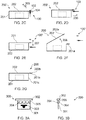
- FIG 1A schematically illustrates an apparatus 100 configured to fasten a container 201 and a closure 202 in a closed configuration (as shown in Figure 1B ).
- the container 201 and the closure 202 each comprise an aperture 201 a, 202a.
- the apparatus 100 comprises:
- the apparatus 100 may be a fastening device for fastening the container 201 and its closure 202 in the closed configuration thereby providing securely closed packaging 200' for a product or products 203. Not only may the apparatus 100, in effect, act as a locking mechanism securing the container 201 and its closure 202 in a closed configuration, but also it comprises a hanging slot 103 thereby enabling the apparatus 100 (as well as the container 201 and closure 202 fixed thereto) to be hung, for example, in a retail environment. Thus the apparatus 100 can be used, in combination with the container 201 and closure 202 to form a retail package 200'.
- the "container” 201 may correspond to a housing, box, compartment or base portion for containing a product 203.
- the "closure” 202 may be a lid or cover portion for closing or sealing the container 201 in a closed configuration thereby forming a closable container 200 for the product/products 203.
- the apertures 201 a and 202a may correspond to slots of holes in the container 201 and closure 202.
- the apertures 201 a and 202a may be disposed on the container 201 and closure 202 such that they substantially overlie/overlap one another when the container 201 and closure 202 are in a closed configuration.
- the apparatus 100 is separate, distinct and non-integral with each of the container 201 and the closure 202.
- the apparatus 100 and it constituent portions and parts may be formed as a single integral member.
- the insertion portion 101 is configured (i.e. shaped and dimensioned) such that it may pass through each of the apertures 201 a and 202a of the container 201 and the closure 202.
- the restraining portion 102 is configured (i.e. shaped and dimensioned) so as to prevent passage of the restraining portion 102 through the apertures 201 a and 202a.
- the dimensions of the insertion portion 101 e.g. its width and thickness
- the dimensions of the restraining portion 102 are configured to be greater than the dimensions of the apertures 201 a and 202a.
- the insertion portion 101 may correspond to an insertion member or insertable tab of the apparatus 100 that is sized and dimensioned to pass through the apertures 201 a and 202a of the container 201 and the closure 202.
- the insertion portion 101 may be dimensioned so as to closely correspond to the dimensions of the apertures 201 a and 202a, albeit of slightly lower dimensions, so as to ensure a tight fit of the insertion portion 101 to the apertures 201 a and 202a.
- the restraining portion 102 may correspond to a retention tab having a flange/projecting rim/rib or collar part having dimensions greater than the dimensions of the apertures 201 a and 202a.
- the hanging slot 103 may correspond to a hanging hole, hang tab or any suitable means to enable suspension therefrom, for example so as to enable hanging from a hook/rail/rack in a retail environment.
- the mechanism 104 for impeding removal of the insertion portion 101 from the apertures 201 a and 202a may comprise means configured to enable/facilitate insertion through the apertures 201 a and 202a in a direction of insertion but configured to prevent/impede removal of the inserted insertion portion 101 in an opposite direction. This may be achieved by any suitable means, not least for example via a one way insertion mechanism/non-return latches/detent/flexing barbs and the like as well as a biased/sprung loaded non-return mechanism.
- Figure 2A shows the container 201 and closure 202 in an open configuration enabling the product or products 203 to be placed within the container 201 following which the container 201 and closure 202 can be brought into the closed configuration (as shown in Figure 2B ).
- the container 201 and closure 202 are joined together via hinge 204.
- other configurations of containers 201 and closures 202 could be used for example, instead of having a hinged closure 202 and container 201, the closure 202 could be slidably engaged with respect to the container 201 so as to enable them to slide with respect to one another into a closed configuration.
- the closure 202 may screw onto the container 201 into the closed configuration.
- the container 201 and closure 202 each comprise an aperture 201 a and 202a, which are configured and disposed such that, when in the closed configuration, the aperture of the container 201 a and the aperture of the closure 202a are aligned with one another, i.e. such that the apertures 201 a and 202a are substantially co-located and overlap with one another (thereby enabling the insertion of the insertion portion 101 of the apparatus 100 through both of the apertures 201 a and 202a, as shown in Figure 2C .
- Figure 2C shows the container 201 fastened by the apparatus 100 in the closed configuration being held in position between the impeding mechanism 104 (impeding removal of the insertion portion 101 from the apertures 201 a and 202a) and the restraining portion 102 (preventing passage of the restraining portion 102 through the apertures 201 a and 202a).
- This enables the container 201 and the closure 202 to be securely fastened in place between the mechanism 104 and the restraining portion 102, thereby preventing opening of the container 201 and closure 202 as symbolised by arrow 205.
- the configuration of Figure 2C provides a packaging 200' for the product/products 203 that is particularly suitable for being stowed away/stored (e.g. for storage/transportation) so as to have a reduced size/form factor as compared to the configuration of Figure 2D .
- the apparatus 100 is configured to be foldable (as indicated by arrow 206) so as to enable the insertion portion 101 and the hanging slot 103 formed therein to project outwards and away from the container enclosure such that the hanging slot 103 is exposed and available for use, i.e. to enable the package 200' to be hung by the hanging slot 103.
- this enables the apparatus 100 to be folded following insertion so as to facilitate the hanging in a retail environment (or folded away to be stowed when being stored/transported as shown in Figure 2C ).
- the impeding mechanism 104 comprises a folding/crease line that enables the apparatus 100 to fold in such a manner as to impede the removal of the insertion portion 101 from the apertures 201 a and 202a.
- the apparatus 100 may further comprise a tamper indicating mechanism configured to indicate tampering of the apparatus 100 when in use, e.g. interference or attempted unfastening of the apparatus 100 from the container 201 and closure 202 due to attempted opening of the container 201 and closure 202.
- a tamper indicating mechanism may comprise the apparatus 100 being frangible, i.e. tearable, breakable, shatterable or friable.
- the apparatus 100 may be configured such that, once inserted into the apertures 201 a and 202a, it is not possible to remove the apparatus 100 without breaking the apparatus 100 thereby providing an indication that the apparatus 100 has been tampered.
- the frangible region of the apparatus 100' may be configured so as to break upon unfastening of the apparatus 100' from the container 201 and closure 202 such that the apparatus 100'can be removed from the container 201 and the closure 202 without damaging either the container 201 or the closure 202 themselves.
- Examples of the apparatus 100 may provide an indication as to tampering of the package 200' (such as opening/attempted opening or prying open of the container 201 and the closure 202 from the fastened closed configuration) but without actually damaging the container 201 and the closure 202 itself. Since the container 201 and closure 202 are not affected by the breaking of the apparatus 100 upon opening of the container 201 and closure202, the container 201 and closure 202 themselves are not functionally nor aesthetically compromised during the opening process and thus can be continued to be used for containing the product/products 203.
- examples of the disclosure may enable the container 201 and closure 202 to serve as a secure tamper proof/tamper indicating retail packaging 200' when used in combination with the apparatus 100, and thereafter, after breaking the apparatus 100 to open the package, the container 201 and closure 202 can be continued to be used as a (non-secure) packaging/closable container 200.
- this avoids the need for specific retail packaging for containing a separate and distinct product package 203, which itself contains the product/products.
- the container 201 and closure 202 may be able to provide dual purpose retail packaging 200' (i.e. with secured/tamper indicating packaging) and, thereafter, product packaging/closable container 200 (i.e.
- the container 201 and closure 202 can continue to be used as a "conventional packaging"/closable container 200 for the product 203, for example in a normal use/domestic environment.
- the aperture 201 a of the container 201 is located on a flange portion 201 b of the container 201.
- the aperture 202a of the closure 202 is located on a flange portion 202b of the closure 202.
- Such flange portions 201 b and 202b are portions of the container 201 and the closure 202 that overlap with one another in a closed configuration.
- the apertures 201 a and 202a are located on the respective flange portions 201b and 202b in positions such that the apertures 201 a and 202b substantially align with one another.
- it is to be appreciated that other configurations and positions of the apertures 201 a and 202a are possible.
- the aperture 201 a of the container 201 may instead be located in a side end wall 201 c of the container 201.
- the closure 202 may be provided with a corresponding overlapping side end wall (not shown) which overlaps the side end wall 201 c of the container 201 and the aperture 202a of the closure 202 may be located within such an overlapping side wall of the closure 201.
- Figures 3A and 3B show a plan view and a side on end view respectively of an apparatus 300 according to a further example of the present disclosure.
- the apparatus 300 comprises an insertion portion 301, restraining portion 302 and hanging slot 303 similar to that as described above.
- An impeding mechanism 304 takes the form of flexible barbs that flexibly protrude outwards so as to provide a one way insertion mechanism of the insertion portion 301 through the apertures 201 a and 202a of the container 201 and closure 202.
- a frangible portion 305 is also provided, for example in the form of a weakened section of the apparatus 300 which is readily breakable without damaging the container 201 and the closure 202 itself thereby providing tamper indicating means that may not damage or adversely affect the container 201 and closure 202.
- the hanging slot 303 is shown as a euro hook. However, the hanging slot 303 may alternatively comprise any suitable aperture or slot suitable for enabling the apparatus 300 to be hung, for example, on a rail or display rack in a retail environment.
- aspects of the present disclosure also extend to a method for fastening the container 201 in the disclosure.
- the method comprises: placing the container 201 and closure 202 in a closed configuration and fastening the container 201 and closure 202 in the closed configuration by: partially inserting the apparatus 100 through the aperture 201 a of the container 201 and the aperture 202a of the closure 202.
- various examples of the present invention may provide an apparatus 100 for fastening a container 201 and closure 202 so as to securely retain the container enclosure in a closed configuration.
- the mere act of partial insertion of the apparatus 100 may ensure the automated fastening of the container 201 and closure 202 thereby providing a simple way in which to fasten the container enclosure that may not require multiple parts or assembly of the application or the use of adhesive (e.g. the application of tamper indicating stickers/labels).
- the apparatus 100 may be easily attached to the container 201 and closure 202 providing easy installation.
- the attachment to the container 201 and closure 202 avoid damaging or deforming the container 201 and closure 202 but moreover the removal of the apparatus 100, by breaking the apparatus 100, likewise may not damage or deform the container 201 and closure 202 thus not affecting the functionality or appearance of the same such that they can continue to be used as an aesthetically pleasing package for the product 203 outside of the retail environment.
- Examples of the invention may avoid the need for separate retail packaging and product packaging as the apparatus 100 effectively provides the requirements for retail packaging (tamper indicating and hanging slot 103 which can be removed when no longer required for a retail environment) leaving just the container 201 and closure 202 to act as a conventional package for the product/products 203.
- the apparatus may be configured such that is may be easily removed by a consumer/user.
- the apparatus may comprise a frangible region (not least for example a tear off strip) to enable the apparatus to be easily removed by the consumer so as to leaving the container 201 and closure 202 to act as a conventional package for the product/products.
- references to "a/an/the” [feature, element, component, means...] are to be interpreted as “at least one” [feature, element, component, means...] unless explicitly stated otherwise.
Abstract
Description
- Examples of the present disclosure relate to an apparatus, system and method for fastening a container and a closure. Some examples, though without prejudice to the foregoing, relate to a fastening device for fastening a container and a closure to form retail packaging for a product/products.
- Conventional retail packaging, not least for example packaging that is designed to be hung from rails in a retail environment, is not always optimal. Retail packaging may typically be required to securely contain a product/products so as to impede or indicate opening or interference of the retail package. For such retail packages, the act of opening the retail package may at least partially destroy or disfigure the retail package. Thus, the retail package, once opened, may be compromised and rendered unsuitable, suboptimal or visually unappealing for subsequent use in storing its product/products.
- The listing or discussion of any prior-published document or any background in this specification should not necessarily be taken as an acknowledgement that the document or background is part of the state of the art or is common general knowledge. One or more aspects/examples of the present disclosure may or may not address one or more of the background issues.
- According to various but not necessarily all examples of the disclosure there is provided an apparatus configured to fasten a container and a closure for the same in a closed configuration, wherein said container and said closure each comprise an aperture, the apparatus comprising:
- an insertion portion configured for insertion through said apertures when said container and said closure are in said closed configuration;
- a restraining portion configured to prevent passage of the restraining portion through said apertures; and
- a hanging slot, and
- a mechanism configured to impede removal of the insertion portion from said apertures once the insertion portion has been inserted through said apertures such that the container and the closure are fastened together between the mechanism and the restraining portion.
- According to various but not necessarily all examples of the disclosure there is provided a system comprising: the apparatus as above, said container, and said closure.
- According to various but not necessarily all examples of the disclosure there is provided a method comprising:
- placing a container and a closure in a closed configuration;
- fastening the container and closure in the closed configuration by:
- partially inserting the apparatus as mentioned above through an aperture of the container and an aperture of the closure.
- According to various but not necessarily all examples of the disclosure there is provided an apparatus configured to fasten a container and a closure in a closed configuration, wherein said container and said closure each comprise an aperture, the apparatus comprising:
- insertion means configured for insertion through said apertures when said container and said closure are in said closed configuration;
- restraining means configured to prevent passage of the restraining means through said apertures; and
- hanging means configured to enable the apparatus to be hung,and
- impeding means configured to impede removal of the insertion portion from said apertures once the insertion means has been inserted through said apertures such that the container and the closure are fastened between the impeding means and the restraining means.
- For a better understanding of various examples of the present disclosure that are useful for understanding the detailed description and certain embodiments of the invention, reference will now be made by way of example only to the accompanying drawings in which:
-
Figures 1A and 1B schematically illustrate an apparatus according to the present disclosure; -
Figures 2A to 2G schematically illustrate use of an apparatus according to the present disclosure; and -
Figures 3A and 3B schematically illustrate use of the apparatus ofFigure 1 . - The Figures are not necessarily to scale. Certain features and views of the Figures may be shown schematically or exaggerated in scale in the interest of clarity and conciseness. For example, the dimensions of some elements in the figures may be exaggerated relative to other elements to aid explication.
- Examples of an apparatus, system and method for fastening a container and a closure for the same will now be described with reference to the Figures. The Figures focus on the functional components necessary for describing the operation of the apparatus. Similar reference numerals are used in the Figures to designate similar features. For clarity, all reference numerals are not necessarily displayed in all figures.
-
Figure 1A schematically illustrates anapparatus 100 configured to fasten acontainer 201 and aclosure 202 in a closed configuration (as shown inFigure 1B ). Thecontainer 201 and theclosure 202 each comprise anaperture apparatus 100 comprises: - an
insertion portion 101 configured for insertion through saidapertures container 201 and theclosure 202 are in the closed configuration; - a
restraining portion 102 configured to prevent passage of therestraining portion 102 through theapertures - a
hanging slot 103, and - a
mechanism 104 configured to impede removal of theinsertion portion 101 from theapertures insertion portion 101 has been inserted through theapertures container 201 and theclosure 202 are fastened together between themechanism 104 and therestraining portion 102. - The
apparatus 100 may be a fastening device for fastening thecontainer 201 and itsclosure 202 in the closed configuration thereby providing securely closedpackaging 200' for a product orproducts 203. Not only may theapparatus 100, in effect, act as a locking mechanism securing thecontainer 201 and itsclosure 202 in a closed configuration, but also it comprises ahanging slot 103 thereby enabling the apparatus 100 (as well as thecontainer 201 andclosure 202 fixed thereto) to be hung, for example, in a retail environment. Thus theapparatus 100 can be used, in combination with thecontainer 201 andclosure 202 to form aretail package 200'. - As used herein, the "container" 201 may correspond to a housing, box, compartment or base portion for containing a
product 203. The "closure" 202 may be a lid or cover portion for closing or sealing thecontainer 201 in a closed configuration thereby forming aclosable container 200 for the product/products 203. Theapertures container 201 andclosure 202. Theapertures container 201 andclosure 202 such that they substantially overlie/overlap one another when thecontainer 201 andclosure 202 are in a closed configuration. - In various examples of the disclosure, the
apparatus 100 is separate, distinct and non-integral with each of thecontainer 201 and theclosure 202. Theapparatus 100 and it constituent portions and parts may be formed as a single integral member. - The
insertion portion 101 is configured (i.e. shaped and dimensioned) such that it may pass through each of theapertures container 201 and theclosure 202. By contrast, therestraining portion 102 is configured (i.e. shaped and dimensioned) so as to prevent passage of therestraining portion 102 through theapertures Figure 1A , the dimensions of the insertion portion 101 (e.g. its width and thickness) are configured to be less than the dimensions of theapertures apertures - The
insertion portion 101 may correspond to an insertion member or insertable tab of theapparatus 100 that is sized and dimensioned to pass through theapertures container 201 and theclosure 202. In some examples, theinsertion portion 101 may be dimensioned so as to closely correspond to the dimensions of theapertures insertion portion 101 to theapertures - The
restraining portion 102 may correspond to a retention tab having a flange/projecting rim/rib or collar part having dimensions greater than the dimensions of theapertures - The hanging
slot 103 may correspond to a hanging hole, hang tab or any suitable means to enable suspension therefrom, for example so as to enable hanging from a hook/rail/rack in a retail environment. - The
mechanism 104 for impeding removal of theinsertion portion 101 from theapertures apertures insertion portion 101 in an opposite direction. This may be achieved by any suitable means, not least for example via a one way insertion mechanism/non-return latches/detent/flexing barbs and the like as well as a biased/sprung loaded non-return mechanism. - Reference is now made to
Figures 2A to 2G that illustrate use of theapparatus 100 in fastening thecontainer 201 and theclosure 202 in a closed configuration. -
Figure 2A shows thecontainer 201 andclosure 202 in an open configuration enabling the product orproducts 203 to be placed within thecontainer 201 following which thecontainer 201 andclosure 202 can be brought into the closed configuration (as shown inFigure 2B ). In this example, thecontainer 201 andclosure 202 are joined together viahinge 204. However, it is to be appreciated that in other examples, other configurations ofcontainers 201 andclosures 202 could be used for example, instead of having a hingedclosure 202 andcontainer 201, theclosure 202 could be slidably engaged with respect to thecontainer 201 so as to enable them to slide with respect to one another into a closed configuration. In further examples, theclosure 202 may screw onto thecontainer 201 into the closed configuration. - The
container 201 andclosure 202 each comprise anaperture container 201 a and the aperture of theclosure 202a are aligned with one another, i.e. such that theapertures insertion portion 101 of theapparatus 100 through both of theapertures Figure 2C . -
Figure 2C shows thecontainer 201 fastened by theapparatus 100 in the closed configuration being held in position between the impeding mechanism 104 (impeding removal of theinsertion portion 101 from theapertures portion 102 through theapertures container 201 and theclosure 202 to be securely fastened in place between themechanism 104 and the restrainingportion 102, thereby preventing opening of thecontainer 201 andclosure 202 as symbolised byarrow 205. The configuration ofFigure 2C provides apackaging 200' for the product/products 203 that is particularly suitable for being stowed away/stored (e.g. for storage/transportation) so as to have a reduced size/form factor as compared to the configuration ofFigure 2D . - As illustrated in
Figure 2D , theapparatus 100 is configured to be foldable (as indicated by arrow 206) so as to enable theinsertion portion 101 and the hangingslot 103 formed therein to project outwards and away from the container enclosure such that the hangingslot 103 is exposed and available for use, i.e. to enable thepackage 200' to be hung by the hangingslot 103. Advantageously, this enables theapparatus 100 to be folded following insertion so as to facilitate the hanging in a retail environment (or folded away to be stowed when being stored/transported as shown inFigure 2C ). In some examples, the impedingmechanism 104 comprises a folding/crease line that enables theapparatus 100 to fold in such a manner as to impede the removal of theinsertion portion 101 from theapertures - The
apparatus 100 may further comprise a tamper indicating mechanism configured to indicate tampering of theapparatus 100 when in use, e.g. interference or attempted unfastening of theapparatus 100 from thecontainer 201 andclosure 202 due to attempted opening of thecontainer 201 andclosure 202. Such tamper indicating mechanism may comprise theapparatus 100 being frangible, i.e. tearable, breakable, shatterable or friable. Theapparatus 100 may be configured such that, once inserted into theapertures apparatus 100 without breaking theapparatus 100 thereby providing an indication that theapparatus 100 has been tampered.Figure 2E illustrates the apparatus 100' having been broken (as indicated by double headed arrow 207) along a frangible/weakened section of the apparatus 100' between the restrainingportion 102 and the impedingmechanism 104, thereby separating theinsertion portion 101 and the restrainingportion 102 and thus unfastening thecontainer 201 and theclosure 202 so as to enable theclosure 201 andcontainer 202 to be opened (as represented by arrow 208) to an open configuration as shown inFigure 2F . - The frangible region of the apparatus 100' may be configured so as to break upon unfastening of the apparatus 100' from the
container 201 andclosure 202 such that the apparatus 100'can be removed from thecontainer 201 and theclosure 202 without damaging either thecontainer 201 or theclosure 202 themselves. - Examples of the
apparatus 100 may provide an indication as to tampering of thepackage 200' (such as opening/attempted opening or prying open of thecontainer 201 and theclosure 202 from the fastened closed configuration) but without actually damaging thecontainer 201 and theclosure 202 itself. Since thecontainer 201 andclosure 202 are not affected by the breaking of theapparatus 100 upon opening of thecontainer 201 and closure202, thecontainer 201 andclosure 202 themselves are not functionally nor aesthetically compromised during the opening process and thus can be continued to be used for containing the product/products 203. Advantageously, examples of the disclosure may enable thecontainer 201 andclosure 202 to serve as a secure tamper proof/tamper indicatingretail packaging 200' when used in combination with theapparatus 100, and thereafter, after breaking theapparatus 100 to open the package, thecontainer 201 andclosure 202 can be continued to be used as a (non-secure) packaging/closable container 200. Advantageously, this avoids the need for specific retail packaging for containing a separate anddistinct product package 203, which itself contains the product/products. Instead, in examples of the present disclosure, thecontainer 201 andclosure 202 may be able to provide dual purposeretail packaging 200' (i.e. with secured/tamper indicating packaging) and, thereafter, product packaging/closable container 200 (i.e. a reusablyopenable container 201 and closure 202). In such examples, thecontainer 201 andclosure 202 may be configured so as to mate/interengage with one another so as to releasably retain thecontainer 201 and theclosure 202 in the enclosed configuration (as shown inFigure 2G ). Any such suitable releasably retaining mechanism may be used in this, not least for example a snap fit mechanism that enables thecontainer 201 and theclosure 202 to be retained in a closed configuration without use of theapparatus 100, albeit in a non-secure non-tamper indicative manner. With such examples, after theapparatus 100 has served its purpose of securing thecontainer 201 and theclosure 202 in a secure tamper indicating package, i.e. so as to act as aretail packaging 200' in a retail environment, thereafter, thecontainer 201 andclosure 202 can continue to be used as a "conventional packaging"/closable container 200 for theproduct 203, for example in a normal use/domestic environment. - In the
containers 201 andclosures 202 shown in the figures, theaperture 201 a of thecontainer 201 is located on aflange portion 201 b of thecontainer 201. Likewise, theaperture 202a of theclosure 202 is located on aflange portion 202b of theclosure 202.Such flange portions container 201 and theclosure 202 that overlap with one another in a closed configuration. Theapertures respective flange portions apertures apertures aperture 201 a on projectingflange portion 201 b, theaperture 201 a of thecontainer 201 may instead be located in aside end wall 201 c of thecontainer 201. In which case theclosure 202 may be provided with a corresponding overlapping side end wall (not shown) which overlaps theside end wall 201 c of thecontainer 201 and theaperture 202a of theclosure 202 may be located within such an overlapping side wall of theclosure 201. -
Figures 3A and 3B show a plan view and a side on end view respectively of anapparatus 300 according to a further example of the present disclosure. Theapparatus 300 comprises aninsertion portion 301, restrainingportion 302 and hangingslot 303 similar to that as described above. An impedingmechanism 304 takes the form of flexible barbs that flexibly protrude outwards so as to provide a one way insertion mechanism of theinsertion portion 301 through theapertures container 201 andclosure 202. Afrangible portion 305 is also provided, for example in the form of a weakened section of theapparatus 300 which is readily breakable without damaging thecontainer 201 and theclosure 202 itself thereby providing tamper indicating means that may not damage or adversely affect thecontainer 201 andclosure 202. The hangingslot 303 is shown as a euro hook. However, the hangingslot 303 may alternatively comprise any suitable aperture or slot suitable for enabling theapparatus 300 to be hung, for example, on a rail or display rack in a retail environment. - Aspects of the present disclosure also extend to a method for fastening the
container 201 in the disclosure. The method comprises: placing thecontainer 201 andclosure 202 in a closed configuration and fastening thecontainer 201 andclosure 202 in the closed configuration by: partially inserting theapparatus 100 through theaperture 201 a of thecontainer 201 and theaperture 202a of theclosure 202. - Advantageously, various examples of the present invention may provide an
apparatus 100 for fastening acontainer 201 andclosure 202 so as to securely retain the container enclosure in a closed configuration. Advantageously, due to the impedingmechanism 104 and the restrainingportion 102, the mere act of partial insertion of theapparatus 100 may ensure the automated fastening of thecontainer 201 andclosure 202 thereby providing a simple way in which to fasten the container enclosure that may not require multiple parts or assembly of the application or the use of adhesive (e.g. the application of tamper indicating stickers/labels). Thus, theapparatus 100 may be easily attached to thecontainer 201 andclosure 202 providing easy installation. Not only may the attachment to thecontainer 201 andclosure 202 avoid damaging or deforming thecontainer 201 andclosure 202 but moreover the removal of theapparatus 100, by breaking theapparatus 100, likewise may not damage or deform thecontainer 201 andclosure 202 thus not affecting the functionality or appearance of the same such that they can continue to be used as an aesthetically pleasing package for theproduct 203 outside of the retail environment. - Examples of the invention may avoid the need for separate retail packaging and product packaging as the
apparatus 100 effectively provides the requirements for retail packaging (tamper indicating and hangingslot 103 which can be removed when no longer required for a retail environment) leaving just thecontainer 201 andclosure 202 to act as a conventional package for the product/products 203. - The apparatus may be configured such that is may be easily removed by a consumer/user. For example, the apparatus may comprise a frangible region (not least for example a tear off strip) to enable the apparatus to be easily removed by the consumer so as to leaving the
container 201 andclosure 202 to act as a conventional package for the product/products. - The examples of the present disclosure and the accompanying claims may be suitably combined in any manner apparent to one of ordinary skill in the art.
- Features described in the preceding description may be used in combinations other than the combinations explicitly described. Although functions have been described with reference to certain features, those functions may be performable by other features whether described or not. Although features have been described with reference to certain examples, those features may also be present in other examples whether described or not. Although various examples of the present disclosure have been described in the preceding paragraphs, it should be appreciated that modifications to the examples given can be made without departing from the scope of the invention as set out in the claims.
- The term 'comprise' is used in this document with an inclusive not an exclusive meaning. That is any reference to X comprising Y indicates that X may comprise only one Y or may comprise more than one Y. If it is intended to use 'comprise' with an exclusive meaning then it will be made clear in the context by referring to "comprising only one ..." or by using "consisting".
- In this description, reference has been made to various examples. The description of features or functions in relation to an example indicates that those features or functions are present in that example. The use of the term 'example' or 'for example' or 'may' in the text denotes, whether explicitly stated or not, that such features or functions are present in at least the described example, whether described as an example or not, and that they can be, but are not necessarily, present in some or all other examples. Thus 'example', 'for example' or 'may' refers to a particular instance in a class of examples. A property of the instance can be a property of only that instance or a property of the class or a property of a sub-class of the class that includes some but not all of the instances in the class.
- In this description, references to "a/an/the" [feature, element, component, means...] are to be interpreted as "at least one" [feature, element, component, means...] unless explicitly stated otherwise.
- The above description describes some examples of the present disclosure however those of ordinary skill in the art will be aware of possible alternative structures and method features which offer equivalent functionality to the specific examples of such structures and features described herein above and which for the sake of brevity and clarity have been omitted from the above description. Nonetheless, the above description should be read as implicitly including reference to such alternative structures and method features which provide equivalent functionality unless such alternative structures or method features are explicitly excluded in the above description of the examples of the present disclosure.
- Whilst endeavouring in the foregoing specification to draw attention to those features of examples of the present disclosure believed to be of particular importance it should be understood that the applicant claims protection in respect of any patentable feature or combination of features hereinbefore referred to and/or shown in the drawings whether or not particular emphasis has been placed thereon.
Claims (15)
- An apparatus configured to fasten a container and a closure in a closed configuration, wherein said container and said closure each comprise an aperture, the apparatus comprising:an insertion portion configured for insertion through said apertures when said container and said closure are in said closed configuration;a restraining portion configured to prevent passage of the restraining portion through said apertures; andwherein the insertion portion comprises:a hanging slot, anda mechanism configured to impede removal of the insertion portion from said apertures once the insertion portion has been inserted through said apertures such that the container and the closure are fastened between the mechanism and the restraining portion.
- The apparatus of claim 1, wherein the apparatus is foldable.
- The apparatus of claim 2, wherein the apparatus is configurable into a folded position, wherein the folded position is configured to impede removal of the insertion portion from said apertures following insertion of the insertion portion into said apertures.
- The apparatus of any one or more of the previous claims, wherein the insertion portion is configured to enable insertion through said apertures in a direction of insertion, and is configured to prevent removal of the inserted insertion portion in an opposite direction.
- The apparatus of any one or more of the previous claims, wherein the apparatus comprises a tamper indicating mechanism configured to indicate tampering upon unfastening of the apparatus from said container and closure.
- The apparatus of any one or more of the previous claims, wherein the apparatus is configured to be frangible.
- The apparatus of any one or more of the previous claims, wherein the apparatus comprises a frangible region configured to break upon unfastening of the apparatus from said container and closure such that the apparatus can be removed from the container and the closure without damaging the container and the closure.
- The apparatus of any one or more of the previous claims, wherein the hanging slot is integrally formed with the apparatus.
- The apparatus of any one or more of the previous claims, wherein the hanging slot comprises one or more of:an aperture for enabling the apparatus to be hung on a rack, anda euro hook.
- The apparatus of any one or more of the previous claims, wherein the apparatus is a fastening device for fastening said container and said closure in said closed configuration.
- A system comprising:a container having an aperture;a closure having an aperture; andthe apparatus as claimed in any one or more of the previous claims.
- The system as claimed in claim 11, wherein the apertures are configured such that, when the container and the closure are in the closed configuration, the apertures are aligned.
- The system as claimed in claim 11 or 12, wherein the container comprises a flange portion and wherein the aperture of the container is located in the flange portion.
- The system as claimed in any of claims 11 to 13, wherein the closure and the container are either:joined together, orseparate components.
- The system as claimed in any of claims 11 to 15, wherein the container and the closure are configured to inter-engage with one another so as to releasably retain the container and the closure in the closed configuration.
Applications Claiming Priority (1)
| Application Number | Priority Date | Filing Date | Title |
|---|---|---|---|
| GB1520646.9A GB2544737B (en) | 2015-11-23 | 2015-11-23 | System and method for fastening a container and a closure |
Publications (2)
| Publication Number | Publication Date |
|---|---|
| EP3170764A1 true EP3170764A1 (en) | 2017-05-24 |
| EP3170764B1 EP3170764B1 (en) | 2018-12-12 |
Family
ID=55133232
Family Applications (1)
| Application Number | Title | Priority Date | Filing Date |
|---|---|---|---|
| EP16197605.5A Not-in-force EP3170764B1 (en) | 2015-11-23 | 2016-11-07 | System for fastening a container and a closure |
Country Status (3)
| Country | Link |
|---|---|
| US (1) | US10370159B2 (en) |
| EP (1) | EP3170764B1 (en) |
| GB (1) | GB2544737B (en) |
Families Citing this family (2)
| Publication number | Priority date | Publication date | Assignee | Title |
|---|---|---|---|---|
| CN107448062B (en) * | 2017-09-12 | 2023-05-12 | 珠海金志科技有限公司 | Sealing buckle and banknote box |
| CN110626631B (en) * | 2018-06-21 | 2023-07-18 | 北京中集精新相能科技有限公司 | Lock catch mechanism for box |
Citations (3)
| Publication number | Priority date | Publication date | Assignee | Title |
|---|---|---|---|---|
| EP0751076A1 (en) * | 1995-06-27 | 1997-01-02 | Vynex S.A. | Packaging for sales presentation of small and medium sized articles |
| EP2502525A1 (en) * | 2011-03-22 | 2012-09-26 | Wilkins, Andre Philip | Removable package hanger |
| GB2523179A (en) * | 2014-02-18 | 2015-08-19 | Logistical Security Ltd | Security packaging |
Family Cites Families (51)
| Publication number | Priority date | Publication date | Assignee | Title |
|---|---|---|---|---|
| US3132742A (en) * | 1963-10-28 | 1964-05-12 | Service Poly Pak Inc | Merchandise bag and hanger combination |
| US4106801A (en) * | 1975-04-01 | 1978-08-15 | Lima Castro Netto E De | One piece security seal and new sealing system |
| US4349102A (en) * | 1981-02-11 | 1982-09-14 | Murray Strongwater | Packaging device |
| US4356919A (en) | 1981-04-23 | 1982-11-02 | Arthur Matney | Hang hole device for display of package |
| DE8416122U1 (en) * | 1984-05-26 | 1985-09-26 | Eichner Organisation Kg, 8630 Coburg | Containers for data carriers, in particular for floppy disks |
| DE8501735U1 (en) * | 1985-01-24 | 1985-03-21 | Fa. Georg Knoblauch, 7928 Giengen | Container in the form of a cassette can or the like for storing objects |
| US4632242A (en) * | 1985-06-06 | 1986-12-30 | C. Itoh & Co. (America) Inc. | Display package having a retractable hanger |
| GB2230247B (en) * | 1989-04-13 | 1992-11-11 | Andre Philip Wilkins | Apparatus for producing suspension packs for articles |
| US5037000A (en) * | 1989-08-23 | 1991-08-06 | Plymouth Rubber Company | Rubber band dispenser |
| DE29504823U1 (en) * | 1995-03-22 | 1995-05-18 | Karl Lenz Gmbh & Co Kg | Hanging sales pack for self-service facilities |
| US5505351A (en) | 1995-06-22 | 1996-04-09 | Najarian; John | Hanger for a pre-tied necktie assembly |
| US5672238A (en) | 1995-07-12 | 1997-09-30 | Minnesota Mining And Manufacturing Company | Hanger sheet and tape dispenser combination |
| JPH09118331A (en) | 1995-10-20 | 1997-05-06 | Sony Corp | Packaging box |
| DE19732753A1 (en) * | 1997-07-30 | 1999-02-04 | Beiersdorf Ag | Plastic box has separate square tab |
| AU3316000A (en) | 1999-01-29 | 2000-08-18 | Mdc Corporation Inc. | Roll dispenser package |
| US6401921B1 (en) | 2000-06-27 | 2002-06-11 | Kds Corporation | Tape measure display container and tape measure |
| AU2006202190A1 (en) | 2000-07-14 | 2006-06-15 | In Vivo Systems Limited | Tamper Proof Slide Cover Container |
| AUPQ876200A0 (en) | 2000-07-14 | 2000-08-03 | Western Research & Development Pty Ltd | Tamper proof slide cover container |
| AUPQ887000A0 (en) | 2000-07-19 | 2000-08-10 | Western Research & Development Pty Ltd | Tamper proof hinged lid container |
| JP2002225844A (en) | 2001-01-26 | 2002-08-14 | Jujo Central Co Ltd | Slide carton with suspending tab |
| US6679379B1 (en) | 2002-07-30 | 2004-01-20 | Jui-Chien Kao | Tool suspension device |
| DE10239711A1 (en) | 2002-08-29 | 2004-03-11 | Beiersdorf Ag | Resealable, square-shaped folding box with a break-away safety lock and hanging tab |
| DE10252683A1 (en) | 2002-11-13 | 2004-06-03 | Beiersdorf Ag | Resealable, rectangular box with side opening and hanging tab |
| US6905024B1 (en) | 2003-09-17 | 2005-06-14 | F.A.F. Incorporated | Anti-theft display box assembly |
| US7735678B2 (en) | 2004-04-05 | 2010-06-15 | Loctite (R&D) Limited | Container and combination packaging |
| US7281630B2 (en) | 2004-09-17 | 2007-10-16 | Nokia Corporation | Packaging |
| US7624865B2 (en) | 2005-03-08 | 2009-12-01 | Robert Bosch Gmbh | Specialty product hang tag |
| US7175151B2 (en) | 2005-03-22 | 2007-02-13 | Chi-Tsai Chang | Hand tool suspension device |
| US7565973B2 (en) | 2007-05-03 | 2009-07-28 | Chi-Tsai Chang | Suspension tag for socket wrench |
| US20090236351A1 (en) * | 2008-03-18 | 2009-09-24 | Lewis Chu | Hangers, package assemblies and methods of readying packages for display |
| US8104637B2 (en) * | 2008-11-24 | 2012-01-31 | Scosche Industries, Inc. | Pop-up hanger on drum |
| CA2823329A1 (en) | 2008-12-01 | 2010-06-10 | Colgate-Palmolive Company | A display carton for a plurality of products |
| US20100140267A1 (en) | 2008-12-05 | 2010-06-10 | Robert Sellari | Container with hang tab and method of forming the same |
| ES1070308Y (en) | 2009-05-12 | 2009-10-29 | Hair Brush Iberica S L | EXHIBITOR BAG WITH HANGER AND SECURITY CLOSURE |
| FR2948104B1 (en) | 2009-07-16 | 2013-11-01 | Ind Distrib Service Ids | FOLDABLE CONTAINER AND ASSEMBLY COMPRISING SAID FOLDABLE CONTAINER AND SUSPENSION DEVICE |
| MX363227B (en) | 2009-08-14 | 2019-03-15 | Bedford Ind Inc | Hang tab and product tag assembly, and method of use. |
| WO2011043916A1 (en) | 2009-10-08 | 2011-04-14 | Meadwestvaco Corporation | Releasable security device and packages using the device |
| US8308119B2 (en) * | 2010-05-10 | 2012-11-13 | Target Brands, Inc. | Retail product assembly with hanger |
| GB2480645B (en) | 2010-05-26 | 2015-08-26 | Mainetti Uk Ltd | Device for suspending a box from a rail and method of recycling such a device |
| EP2616350B1 (en) | 2010-09-16 | 2016-07-20 | DOO International Pty Ltd | A tamper evident container |
| TWM399844U (en) | 2010-09-17 | 2011-03-11 | Rote Mate Industry Co Ltd | Padlock container structure |
| CN202347962U (en) | 2011-11-21 | 2012-07-25 | 杭州巨星工具有限公司 | Pliers plastic hanger |
| CN202530900U (en) | 2011-12-12 | 2012-11-14 | 杭州巨星工具有限公司 | Antitheft hanging sheet for screwdriver |
| US8443972B1 (en) | 2011-12-23 | 2013-05-21 | Robert Bosch Gmbh | Hang tag assembly for a hole saw |
| US8607987B2 (en) | 2012-04-19 | 2013-12-17 | Nokia Corporation | Packaging system |
| US9150327B2 (en) | 2012-04-25 | 2015-10-06 | Moshe Yair Begim | Folding box with removable handle |
| US9656788B2 (en) | 2012-09-28 | 2017-05-23 | Mtd Products Inc | Packaging assembly for a replacement mower blade |
| US10060461B2 (en) | 2013-03-12 | 2018-08-28 | Apple Inc. | Display apparatus |
| WO2015077111A1 (en) * | 2013-11-19 | 2015-05-28 | United Surgical Associates, Inc. | Accessible storage and display box |
| US9352886B2 (en) | 2013-11-21 | 2016-05-31 | Placon Corporation | Trapped element security container |
| DE202014104948U1 (en) | 2014-10-16 | 2014-11-24 | Aries Umweltprodukte, Inh. Dieter Szczesny E. K. | Food dispenser for receiving granular food |
-
2015
- 2015-11-23 GB GB1520646.9A patent/GB2544737B/en not_active Expired - Fee Related
-
2016
- 2016-11-07 EP EP16197605.5A patent/EP3170764B1/en not_active Not-in-force
- 2016-11-14 US US15/351,408 patent/US10370159B2/en not_active Expired - Fee Related
Patent Citations (3)
| Publication number | Priority date | Publication date | Assignee | Title |
|---|---|---|---|---|
| EP0751076A1 (en) * | 1995-06-27 | 1997-01-02 | Vynex S.A. | Packaging for sales presentation of small and medium sized articles |
| EP2502525A1 (en) * | 2011-03-22 | 2012-09-26 | Wilkins, Andre Philip | Removable package hanger |
| GB2523179A (en) * | 2014-02-18 | 2015-08-19 | Logistical Security Ltd | Security packaging |
Also Published As
| Publication number | Publication date |
|---|---|
| US10370159B2 (en) | 2019-08-06 |
| GB2544737B (en) | 2018-11-07 |
| GB201520646D0 (en) | 2016-01-06 |
| US20170144806A1 (en) | 2017-05-25 |
| EP3170764B1 (en) | 2018-12-12 |
| GB2544737A (en) | 2017-05-31 |
Similar Documents
| Publication | Publication Date | Title |
|---|---|---|
| US11117716B2 (en) | Tamper evident container | |
| US8235204B2 (en) | Lockable package with slide tray | |
| US6279746B1 (en) | Reclosable blister pack | |
| US10494161B2 (en) | Tamper evident container | |
| US20040118848A1 (en) | Tamper-evident lid assembly | |
| US8242915B2 (en) | Closure assembly | |
| US8708149B2 (en) | Flip container for blister card medication holders | |
| US20140190969A1 (en) | Tamper-evident container | |
| UA82155C2 (en) | Tamper-evident lid | |
| EP3170764A1 (en) | Apparatus, system and method for fastening a container and a closure | |
| US7316316B2 (en) | Combined receptacle and display card | |
| US20170361980A1 (en) | Tamper evident container | |
| US20040010954A1 (en) | Locking gift box | |
| CN205396936U (en) | Pull ring formula beverage bottle packing carton that guards against falsification | |
| US10988280B2 (en) | Secondary insertion feature for assembled package | |
| JP3182100U (en) | Packaging container | |
| US20110168769A1 (en) | Packaging system and carton | |
| KR20210052842A (en) | A box for the home delivery | |
| GB2540641A (en) | Tamper-evident container structure | |
| JP3183806U (en) | Packaging container | |
| EP3929097A1 (en) | Shipping carton and method for the use thereof | |
| US20190009955A1 (en) | Tamper evident food packages | |
| CN217228574U (en) | Plug-in type anti-counterfeiting packaging box | |
| JP2010173717A (en) | Container | |
| FI90752B (en) | Box provided with dispensing aperture |
Legal Events
| Date | Code | Title | Description |
|---|---|---|---|
| PUAI | Public reference made under article 153(3) epc to a published international application that has entered the european phase |
Free format text: ORIGINAL CODE: 0009012 |
|
| STAA | Information on the status of an ep patent application or granted ep patent |
Free format text: STATUS: THE APPLICATION HAS BEEN PUBLISHED |
|
| AK | Designated contracting states |
Kind code of ref document: A1 Designated state(s): AL AT BE BG CH CY CZ DE DK EE ES FI FR GB GR HR HU IE IS IT LI LT LU LV MC MK MT NL NO PL PT RO RS SE SI SK SM TR |
|
| AX | Request for extension of the european patent |
Extension state: BA ME |
|
| STAA | Information on the status of an ep patent application or granted ep patent |
Free format text: STATUS: REQUEST FOR EXAMINATION WAS MADE |
|
| 17P | Request for examination filed |
Effective date: 20171025 |
|
| RBV | Designated contracting states (corrected) |
Designated state(s): AL AT BE BG CH CY CZ DE DK EE ES FI FR GB GR HR HU IE IS IT LI LT LU LV MC MK MT NL NO PL PT RO RS SE SI SK SM TR |
|
| STAA | Information on the status of an ep patent application or granted ep patent |
Free format text: STATUS: EXAMINATION IS IN PROGRESS |
|
| 17Q | First examination report despatched |
Effective date: 20180124 |
|
| GRAP | Despatch of communication of intention to grant a patent |
Free format text: ORIGINAL CODE: EPIDOSNIGR1 |
|
| STAA | Information on the status of an ep patent application or granted ep patent |
Free format text: STATUS: GRANT OF PATENT IS INTENDED |
|
| INTG | Intention to grant announced |
Effective date: 20180917 |
|
| GRAS | Grant fee paid |
Free format text: ORIGINAL CODE: EPIDOSNIGR3 |
|
| GRAA | (expected) grant |
Free format text: ORIGINAL CODE: 0009210 |
|
| STAA | Information on the status of an ep patent application or granted ep patent |
Free format text: STATUS: THE PATENT HAS BEEN GRANTED |
|
| RBV | Designated contracting states (corrected) |
Designated state(s): AL AT BE BG CH CY CZ DE DK EE ES FI FR GR HR HU IE IS IT LI LT LU LV MC MK MT NL NO PL PT RO RS SE SI SK SM TR |
|
| AK | Designated contracting states |
Kind code of ref document: B1 Designated state(s): AL AT BE BG CH CY CZ DE DK EE ES FI FR GR HR HU IE IS IT LI LT LU LV MC MK MT NL NO PL PT RO RS SE SI SK SM TR |
|
| REG | Reference to a national code |
Ref country code: CH Ref legal event code: EP |
|
| REG | Reference to a national code |
Ref country code: AT Ref legal event code: REF Ref document number: 1075681 Country of ref document: AT Kind code of ref document: T Effective date: 20181215 |
|
| REG | Reference to a national code |
Ref country code: DE Ref legal event code: R096 Ref document number: 602016008116 Country of ref document: DE |
|
| REG | Reference to a national code |
Ref country code: IE Ref legal event code: FG4D |
|
| REG | Reference to a national code |
Ref country code: NL Ref legal event code: MP Effective date: 20181212 |
|
| REG | Reference to a national code |
Ref country code: LT Ref legal event code: MG4D |
|
| PG25 | Lapsed in a contracting state [announced via postgrant information from national office to epo] |
Ref country code: BG Free format text: LAPSE BECAUSE OF FAILURE TO SUBMIT A TRANSLATION OF THE DESCRIPTION OR TO PAY THE FEE WITHIN THE PRESCRIBED TIME-LIMIT Effective date: 20190312 Ref country code: FI Free format text: LAPSE BECAUSE OF FAILURE TO SUBMIT A TRANSLATION OF THE DESCRIPTION OR TO PAY THE FEE WITHIN THE PRESCRIBED TIME-LIMIT Effective date: 20181212 Ref country code: LT Free format text: LAPSE BECAUSE OF FAILURE TO SUBMIT A TRANSLATION OF THE DESCRIPTION OR TO PAY THE FEE WITHIN THE PRESCRIBED TIME-LIMIT Effective date: 20181212 Ref country code: LV Free format text: LAPSE BECAUSE OF FAILURE TO SUBMIT A TRANSLATION OF THE DESCRIPTION OR TO PAY THE FEE WITHIN THE PRESCRIBED TIME-LIMIT Effective date: 20181212 Ref country code: HR Free format text: LAPSE BECAUSE OF FAILURE TO SUBMIT A TRANSLATION OF THE DESCRIPTION OR TO PAY THE FEE WITHIN THE PRESCRIBED TIME-LIMIT Effective date: 20181212 Ref country code: ES Free format text: LAPSE BECAUSE OF FAILURE TO SUBMIT A TRANSLATION OF THE DESCRIPTION OR TO PAY THE FEE WITHIN THE PRESCRIBED TIME-LIMIT Effective date: 20181212 Ref country code: NO Free format text: LAPSE BECAUSE OF FAILURE TO SUBMIT A TRANSLATION OF THE DESCRIPTION OR TO PAY THE FEE WITHIN THE PRESCRIBED TIME-LIMIT Effective date: 20190312 |
|
| REG | Reference to a national code |
Ref country code: AT Ref legal event code: MK05 Ref document number: 1075681 Country of ref document: AT Kind code of ref document: T Effective date: 20181212 |
|
| PG25 | Lapsed in a contracting state [announced via postgrant information from national office to epo] |
Ref country code: GR Free format text: LAPSE BECAUSE OF FAILURE TO SUBMIT A TRANSLATION OF THE DESCRIPTION OR TO PAY THE FEE WITHIN THE PRESCRIBED TIME-LIMIT Effective date: 20190313 Ref country code: SE Free format text: LAPSE BECAUSE OF FAILURE TO SUBMIT A TRANSLATION OF THE DESCRIPTION OR TO PAY THE FEE WITHIN THE PRESCRIBED TIME-LIMIT Effective date: 20181212 Ref country code: RS Free format text: LAPSE BECAUSE OF FAILURE TO SUBMIT A TRANSLATION OF THE DESCRIPTION OR TO PAY THE FEE WITHIN THE PRESCRIBED TIME-LIMIT Effective date: 20181212 Ref country code: AL Free format text: LAPSE BECAUSE OF FAILURE TO SUBMIT A TRANSLATION OF THE DESCRIPTION OR TO PAY THE FEE WITHIN THE PRESCRIBED TIME-LIMIT Effective date: 20181212 |
|
| PG25 | Lapsed in a contracting state [announced via postgrant information from national office to epo] |
Ref country code: NL Free format text: LAPSE BECAUSE OF FAILURE TO SUBMIT A TRANSLATION OF THE DESCRIPTION OR TO PAY THE FEE WITHIN THE PRESCRIBED TIME-LIMIT Effective date: 20181212 |
|
| PG25 | Lapsed in a contracting state [announced via postgrant information from national office to epo] |
Ref country code: PL Free format text: LAPSE BECAUSE OF FAILURE TO SUBMIT A TRANSLATION OF THE DESCRIPTION OR TO PAY THE FEE WITHIN THE PRESCRIBED TIME-LIMIT Effective date: 20181212 Ref country code: IT Free format text: LAPSE BECAUSE OF FAILURE TO SUBMIT A TRANSLATION OF THE DESCRIPTION OR TO PAY THE FEE WITHIN THE PRESCRIBED TIME-LIMIT Effective date: 20181212 Ref country code: CZ Free format text: LAPSE BECAUSE OF FAILURE TO SUBMIT A TRANSLATION OF THE DESCRIPTION OR TO PAY THE FEE WITHIN THE PRESCRIBED TIME-LIMIT Effective date: 20181212 Ref country code: PT Free format text: LAPSE BECAUSE OF FAILURE TO SUBMIT A TRANSLATION OF THE DESCRIPTION OR TO PAY THE FEE WITHIN THE PRESCRIBED TIME-LIMIT Effective date: 20190412 |
|
| PG25 | Lapsed in a contracting state [announced via postgrant information from national office to epo] |
Ref country code: SK Free format text: LAPSE BECAUSE OF FAILURE TO SUBMIT A TRANSLATION OF THE DESCRIPTION OR TO PAY THE FEE WITHIN THE PRESCRIBED TIME-LIMIT Effective date: 20181212 Ref country code: SM Free format text: LAPSE BECAUSE OF FAILURE TO SUBMIT A TRANSLATION OF THE DESCRIPTION OR TO PAY THE FEE WITHIN THE PRESCRIBED TIME-LIMIT Effective date: 20181212 Ref country code: EE Free format text: LAPSE BECAUSE OF FAILURE TO SUBMIT A TRANSLATION OF THE DESCRIPTION OR TO PAY THE FEE WITHIN THE PRESCRIBED TIME-LIMIT Effective date: 20181212 Ref country code: RO Free format text: LAPSE BECAUSE OF FAILURE TO SUBMIT A TRANSLATION OF THE DESCRIPTION OR TO PAY THE FEE WITHIN THE PRESCRIBED TIME-LIMIT Effective date: 20181212 Ref country code: IS Free format text: LAPSE BECAUSE OF FAILURE TO SUBMIT A TRANSLATION OF THE DESCRIPTION OR TO PAY THE FEE WITHIN THE PRESCRIBED TIME-LIMIT Effective date: 20190412 |
|
| REG | Reference to a national code |
Ref country code: DE Ref legal event code: R097 Ref document number: 602016008116 Country of ref document: DE |
|
| PLBE | No opposition filed within time limit |
Free format text: ORIGINAL CODE: 0009261 |
|
| STAA | Information on the status of an ep patent application or granted ep patent |
Free format text: STATUS: NO OPPOSITION FILED WITHIN TIME LIMIT |
|
| PG25 | Lapsed in a contracting state [announced via postgrant information from national office to epo] |
Ref country code: AT Free format text: LAPSE BECAUSE OF FAILURE TO SUBMIT A TRANSLATION OF THE DESCRIPTION OR TO PAY THE FEE WITHIN THE PRESCRIBED TIME-LIMIT Effective date: 20181212 Ref country code: SI Free format text: LAPSE BECAUSE OF FAILURE TO SUBMIT A TRANSLATION OF THE DESCRIPTION OR TO PAY THE FEE WITHIN THE PRESCRIBED TIME-LIMIT Effective date: 20181212 Ref country code: DK Free format text: LAPSE BECAUSE OF FAILURE TO SUBMIT A TRANSLATION OF THE DESCRIPTION OR TO PAY THE FEE WITHIN THE PRESCRIBED TIME-LIMIT Effective date: 20181212 |
|
| 26N | No opposition filed |
Effective date: 20190913 |
|
| PG25 | Lapsed in a contracting state [announced via postgrant information from national office to epo] |
Ref country code: TR Free format text: LAPSE BECAUSE OF FAILURE TO SUBMIT A TRANSLATION OF THE DESCRIPTION OR TO PAY THE FEE WITHIN THE PRESCRIBED TIME-LIMIT Effective date: 20181212 |
|
| REG | Reference to a national code |
Ref country code: DE Ref legal event code: R119 Ref document number: 602016008116 Country of ref document: DE |
|
| REG | Reference to a national code |
Ref country code: CH Ref legal event code: PL |
|
| PG25 | Lapsed in a contracting state [announced via postgrant information from national office to epo] |
Ref country code: LU Free format text: LAPSE BECAUSE OF NON-PAYMENT OF DUE FEES Effective date: 20191107 Ref country code: CH Free format text: LAPSE BECAUSE OF NON-PAYMENT OF DUE FEES Effective date: 20191130 Ref country code: MC Free format text: LAPSE BECAUSE OF FAILURE TO SUBMIT A TRANSLATION OF THE DESCRIPTION OR TO PAY THE FEE WITHIN THE PRESCRIBED TIME-LIMIT Effective date: 20181212 Ref country code: LI Free format text: LAPSE BECAUSE OF NON-PAYMENT OF DUE FEES Effective date: 20191130 |
|
| REG | Reference to a national code |
Ref country code: BE Ref legal event code: MM Effective date: 20191130 |
|
| PG25 | Lapsed in a contracting state [announced via postgrant information from national office to epo] |
Ref country code: FR Free format text: LAPSE BECAUSE OF NON-PAYMENT OF DUE FEES Effective date: 20191130 Ref country code: IE Free format text: LAPSE BECAUSE OF NON-PAYMENT OF DUE FEES Effective date: 20191107 Ref country code: DE Free format text: LAPSE BECAUSE OF NON-PAYMENT OF DUE FEES Effective date: 20200603 |
|
| PG25 | Lapsed in a contracting state [announced via postgrant information from national office to epo] |
Ref country code: BE Free format text: LAPSE BECAUSE OF NON-PAYMENT OF DUE FEES Effective date: 20191130 |
|
| PG25 | Lapsed in a contracting state [announced via postgrant information from national office to epo] |
Ref country code: CY Free format text: LAPSE BECAUSE OF FAILURE TO SUBMIT A TRANSLATION OF THE DESCRIPTION OR TO PAY THE FEE WITHIN THE PRESCRIBED TIME-LIMIT Effective date: 20181212 |
|
| PG25 | Lapsed in a contracting state [announced via postgrant information from national office to epo] |
Ref country code: MT Free format text: LAPSE BECAUSE OF FAILURE TO SUBMIT A TRANSLATION OF THE DESCRIPTION OR TO PAY THE FEE WITHIN THE PRESCRIBED TIME-LIMIT Effective date: 20181212 Ref country code: HU Free format text: LAPSE BECAUSE OF FAILURE TO SUBMIT A TRANSLATION OF THE DESCRIPTION OR TO PAY THE FEE WITHIN THE PRESCRIBED TIME-LIMIT; INVALID AB INITIO Effective date: 20161107 |
|
| PG25 | Lapsed in a contracting state [announced via postgrant information from national office to epo] |
Ref country code: MK Free format text: LAPSE BECAUSE OF FAILURE TO SUBMIT A TRANSLATION OF THE DESCRIPTION OR TO PAY THE FEE WITHIN THE PRESCRIBED TIME-LIMIT Effective date: 20181212 |