EP3170751A1 - Passive interne eisschutzsysteme für triebwerkseinlässe - Google Patents
Passive interne eisschutzsysteme für triebwerkseinlässe Download PDFInfo
- Publication number
- EP3170751A1 EP3170751A1 EP16170623.9A EP16170623A EP3170751A1 EP 3170751 A1 EP3170751 A1 EP 3170751A1 EP 16170623 A EP16170623 A EP 16170623A EP 3170751 A1 EP3170751 A1 EP 3170751A1
- Authority
- EP
- European Patent Office
- Prior art keywords
- engine
- protection member
- ice protection
- opening
- ice
- Prior art date
- Legal status (The legal status is an assumption and is not a legal conclusion. Google has not performed a legal analysis and makes no representation as to the accuracy of the status listed.)
- Granted
Links
Images


Classifications
-
- F—MECHANICAL ENGINEERING; LIGHTING; HEATING; WEAPONS; BLASTING
- F02—COMBUSTION ENGINES; HOT-GAS OR COMBUSTION-PRODUCT ENGINE PLANTS
- F02C—GAS-TURBINE PLANTS; AIR INTAKES FOR JET-PROPULSION PLANTS; CONTROLLING FUEL SUPPLY IN AIR-BREATHING JET-PROPULSION PLANTS
- F02C7/00—Features, components parts, details or accessories, not provided for in, or of interest apart form groups F02C1/00 - F02C6/00; Air intakes for jet-propulsion plants
- F02C7/04—Air intakes for gas-turbine plants or jet-propulsion plants
- F02C7/05—Air intakes for gas-turbine plants or jet-propulsion plants having provisions for obviating the penetration of damaging objects or particles
- F02C7/055—Air intakes for gas-turbine plants or jet-propulsion plants having provisions for obviating the penetration of damaging objects or particles with intake grids, screens or guards
-
- B—PERFORMING OPERATIONS; TRANSPORTING
- B64—AIRCRAFT; AVIATION; COSMONAUTICS
- B64D—EQUIPMENT FOR FITTING IN OR TO AIRCRAFT; FLIGHT SUITS; PARACHUTES; ARRANGEMENT OR MOUNTING OF POWER PLANTS OR PROPULSION TRANSMISSIONS IN AIRCRAFT
- B64D27/00—Arrangement or mounting of power plants in aircraft; Aircraft characterised by the type or position of power plants
- B64D27/02—Aircraft characterised by the type or position of power plants
- B64D27/10—Aircraft characterised by the type or position of power plants of gas-turbine type
- B64D27/14—Aircraft characterised by the type or position of power plants of gas-turbine type within, or attached to, fuselages
-
- B—PERFORMING OPERATIONS; TRANSPORTING
- B64—AIRCRAFT; AVIATION; COSMONAUTICS
- B64C—AEROPLANES; HELICOPTERS
- B64C27/00—Rotorcraft; Rotors peculiar thereto
- B64C27/04—Helicopters
- B64C27/06—Helicopters with single rotor
-
- B—PERFORMING OPERATIONS; TRANSPORTING
- B64—AIRCRAFT; AVIATION; COSMONAUTICS
- B64D—EQUIPMENT FOR FITTING IN OR TO AIRCRAFT; FLIGHT SUITS; PARACHUTES; ARRANGEMENT OR MOUNTING OF POWER PLANTS OR PROPULSION TRANSMISSIONS IN AIRCRAFT
- B64D33/00—Arrangement in aircraft of power plant parts or auxiliaries not otherwise provided for
- B64D33/02—Arrangement in aircraft of power plant parts or auxiliaries not otherwise provided for of combustion air intakes
- B64D2033/022—Arrangement in aircraft of power plant parts or auxiliaries not otherwise provided for of combustion air intakes comprising bird or foreign object protections
-
- B—PERFORMING OPERATIONS; TRANSPORTING
- B64—AIRCRAFT; AVIATION; COSMONAUTICS
- B64D—EQUIPMENT FOR FITTING IN OR TO AIRCRAFT; FLIGHT SUITS; PARACHUTES; ARRANGEMENT OR MOUNTING OF POWER PLANTS OR PROPULSION TRANSMISSIONS IN AIRCRAFT
- B64D33/00—Arrangement in aircraft of power plant parts or auxiliaries not otherwise provided for
- B64D33/02—Arrangement in aircraft of power plant parts or auxiliaries not otherwise provided for of combustion air intakes
- B64D2033/0233—Arrangement in aircraft of power plant parts or auxiliaries not otherwise provided for of combustion air intakes comprising de-icing means
-
- B—PERFORMING OPERATIONS; TRANSPORTING
- B64—AIRCRAFT; AVIATION; COSMONAUTICS
- B64D—EQUIPMENT FOR FITTING IN OR TO AIRCRAFT; FLIGHT SUITS; PARACHUTES; ARRANGEMENT OR MOUNTING OF POWER PLANTS OR PROPULSION TRANSMISSIONS IN AIRCRAFT
- B64D33/00—Arrangement in aircraft of power plant parts or auxiliaries not otherwise provided for
- B64D33/02—Arrangement in aircraft of power plant parts or auxiliaries not otherwise provided for of combustion air intakes
- B64D2033/0246—Arrangement in aircraft of power plant parts or auxiliaries not otherwise provided for of combustion air intakes comprising particle separators
-
- F—MECHANICAL ENGINEERING; LIGHTING; HEATING; WEAPONS; BLASTING
- F02—COMBUSTION ENGINES; HOT-GAS OR COMBUSTION-PRODUCT ENGINE PLANTS
- F02C—GAS-TURBINE PLANTS; AIR INTAKES FOR JET-PROPULSION PLANTS; CONTROLLING FUEL SUPPLY IN AIR-BREATHING JET-PROPULSION PLANTS
- F02C7/00—Features, components parts, details or accessories, not provided for in, or of interest apart form groups F02C1/00 - F02C6/00; Air intakes for jet-propulsion plants
- F02C7/04—Air intakes for gas-turbine plants or jet-propulsion plants
- F02C7/047—Heating to prevent icing
-
- F—MECHANICAL ENGINEERING; LIGHTING; HEATING; WEAPONS; BLASTING
- F05—INDEXING SCHEMES RELATING TO ENGINES OR PUMPS IN VARIOUS SUBCLASSES OF CLASSES F01-F04
- F05D—INDEXING SCHEME FOR ASPECTS RELATING TO NON-POSITIVE-DISPLACEMENT MACHINES OR ENGINES, GAS-TURBINES OR JET-PROPULSION PLANTS
- F05D2220/00—Application
- F05D2220/30—Application in turbines
- F05D2220/32—Application in turbines in gas turbines
- F05D2220/329—Application in turbines in gas turbines in helicopters
-
- F—MECHANICAL ENGINEERING; LIGHTING; HEATING; WEAPONS; BLASTING
- F05—INDEXING SCHEMES RELATING TO ENGINES OR PUMPS IN VARIOUS SUBCLASSES OF CLASSES F01-F04
- F05D—INDEXING SCHEME FOR ASPECTS RELATING TO NON-POSITIVE-DISPLACEMENT MACHINES OR ENGINES, GAS-TURBINES OR JET-PROPULSION PLANTS
- F05D2230/00—Manufacture
- F05D2230/60—Assembly methods
-
- F—MECHANICAL ENGINEERING; LIGHTING; HEATING; WEAPONS; BLASTING
- F05—INDEXING SCHEMES RELATING TO ENGINES OR PUMPS IN VARIOUS SUBCLASSES OF CLASSES F01-F04
- F05D—INDEXING SCHEME FOR ASPECTS RELATING TO NON-POSITIVE-DISPLACEMENT MACHINES OR ENGINES, GAS-TURBINES OR JET-PROPULSION PLANTS
- F05D2300/00—Materials; Properties thereof
- F05D2300/10—Metals, alloys or intermetallic compounds
- F05D2300/17—Alloys
- F05D2300/171—Steel alloys
-
- F—MECHANICAL ENGINEERING; LIGHTING; HEATING; WEAPONS; BLASTING
- F05—INDEXING SCHEMES RELATING TO ENGINES OR PUMPS IN VARIOUS SUBCLASSES OF CLASSES F01-F04
- F05D—INDEXING SCHEME FOR ASPECTS RELATING TO NON-POSITIVE-DISPLACEMENT MACHINES OR ENGINES, GAS-TURBINES OR JET-PROPULSION PLANTS
- F05D2300/00—Materials; Properties thereof
- F05D2300/60—Properties or characteristics given to material by treatment or manufacturing
- F05D2300/614—Fibres or filaments
Definitions
- This disclosure relates to ice protection systems for inlets, for example, for engine inlets of aircrafts, rotorcrafts, other automobiles or any engine system that operates in an environment in which ice can be formed.
- an ice protection system is provided to reduce ice formation on engine inlet and control ice ingestion by the engine compressor while minimizing impact on engine performances.
- some engine inlets include integrated systems such as heaters to prevent ice accumulation or outside contour passive protection or in a combination of overlapping protection to prevent ice ingestion.
- This disclosure describes passive internal ice protection systems for engine inlets. Such ice protection systems can be used in aircrafts or rotorcrafts and provide protection with a single mesh screen without protruding outside aircraft contour.
- a system includes an engine cover covering a side-facing rotorcraft engine, the engine cover having an opening; and an ice protection member mounted on the engine cover between the opening and the engine, an area of the ice protection member smaller than an area of the opening.
- the ice protection member is configured to partially cover the opening to prevent ice having a particular size from entering into the engine and to allow air flow downstream into the engine.
- the ice protection member can include a mesh screen.
- the mesh screen can be configured to catch and hold the ice with suction generated by an air flow into the engine, the particular size of the ice larger than a size certified for the engine.
- the ice protection member can be configured to catch the ice with the particular size of about slightly wider than a half of the opening.
- the mesh screen can include a plurality of pores each having a pore size of about 0.25 inch up to 0.50 inch.
- the mesh screen can include stainless steel.
- the ice protection member can include a frame surrounding the mesh screen, and the frame can include fiberglass. The ice protection member can be mounted on the engine cover by fastening the frame onto the engine cover.
- the engine cover can be configured to be mounted on a side surface of the rotorcraft that comprises a front end and a back end, and the ice protection member can be mounted on the engine cover close to the back end such that a particular portion of the opening close to the front end remains open.
- An area of the particular portion of the opening, together with an area of porosity through the ice protection member, can be about 85% of the area of the opening.
- the ice protection member can include a first part and a second part positioned with a folding angle.
- the folding angle can be about 90 degree, and the first part extends in a first direction from the back end to the front end, and the second part can extend upwards to the opening in a second direction perpendicular to the first direction.
- the first part can include one or more folding lines parallel to the first direction to accommodate a shape of the engine cover.
- the system can further include one or more brackets configured to hold the first part under the one or more folding lines and be fastened to the second part and further to the engine cover.
- the system can be configured to be a flush type engine inlet, wherein the engine is a helicopter gas turbine engine.
- the system can further include a filter positioned below the opening of the engine cover and between the ice protection member and the engine.
- a mesh screen is framed to form an ice protection member.
- the ice protection member is mounted on an engine cover having an opening, an area of the ice protection member smaller than an area of the opening, the ice protection member partially covering the opening.
- the engine cover is mounted to cover a side-facing rotorcraft engine, such that the ice protection member is positioned between the opening of the engine cover and the engine. During operation, air flows downstream into the engine through the opening and the ice protection member prevents ice with a particular size entering into the engine.
- Mounting the engine cover can include mounting the engine cover on a side surface of the rotorcraft that comprises a front end and a back end, and the ice protection member can be mounted on the engine cover close to the back end such that a particular portion of the opening close to the front end remains open.
- An area of the particular portion of the opening together with an area of porosity through the ice protection member can be about 85% of the area of the opening, and the ice protection member can be configured to hold the ice with the particular size larger than a size certified for the engine.
- the ice protection member can include a first part and a second part positioned with a folding angle, and mounting the ice protection member can include holding the first part with one or more brackets along one or more respective folding lines of the first part and fastening the one or more brackets to the second part and further to the engine cover.
- the engine inlet includes an engine cover covering the engine.
- the engine cover has an opening via which air flows downstream to the engine, e.g., to a compressor of the engine.
- the ice protection member is mounted on the engine cover between the opening and the engine.
- the ice protection member can be positioned below the opening and inside a passage defined from the opening to the compressor of the engine.
- the ice protection member has an area smaller than an area of the opening and is configured to partially cover the opening to prevent ice exceeding a size certified for the engine from entering into the engine and to allow enough air flow downstream into the engine.
- the ice protection member can include a mesh screen that partially covers a percentage of the opening of the inlet, which can prevent the engine from ice congestion and also minimize the impact on engine performances.
- the ice protection member is passive and does not need active components such as heaters and/or monitors. Such a passive ice protection system can reduce system cost and complexity and require no or little maintenance.
- the ice protection member is easy to install and can minimize installation losses.
- this passive internal ice protection member can also be used in any other flow generation system requiring foreign object damage (FOD) protection.
- FOD foreign object damage
- the passive internal ice protection member can be applied for protection from rags, sand, dust, and/or ice.
- FIG. 1A shows a schematic diagram of a rotorcraft 100 according to an embodiment of the disclosure. It should be understood that while the rotorcraft 100 example depicted comprises a helicopter, embodiments of the disclosure are not limited to any particular setting or application, and embodiments may be used in any setting or application requiring FOD protection. Such a setting or application can include, for example, tiltrotor aircrafts, gas turbine systems, automotive transmission systems, to name a few.
- the rotorcraft 100 has a rotor system 102 with multiple rotor blades 104.
- the rotorcraft 100 can further include a fuselage 106, an anti-torque system 108, and an empennage 110.
- An outline or an outer surface of the fuselage 106 can be defined as a contour of the rotorcraft 100.
- the rotorcraft 100 also includes an engine 120 that provides power to the rotor system 102 and/or the anti-torque system 108.
- the engine 120 supplies torque to the rotor system 102 for rotating the rotor blades 104 via a gearbox system 112.
- the gearbox system 112 can include a mast 114 (e.g., a rotating shaft), a gearbox 116, and a gearbox shaft 118.
- the gearbox shaft 118 is configured to be mechanically coupled to the engine 118 and the gearbox 116 and be capable of transmitting torque and rotation.
- the gearbox 116 can be mechanically coupled to the rotor system 102 via the mast 114 that is also capable of transmitting torque and rotation.
- the rotor system 102 has a control system for selectively controlling the pitch of each rotor blade 104 in order to selectively control direction, thrust, and lift of the rotorcraft 100.
- FIG. 1B is a schematic diagram of an example engine inlet 122 of the example rotorcraft 100.
- the engine 120 can be a side-facing engine, and the engine inlet 122 can be a flush type engine inlet for the side-facing engine and positioned on a side face of the fuselage 106.
- the rotorcraft 100 moves forward, air flows backward from a front end of the rotorcraft 100 to a back end of the rotorcraft 100.
- the air can be sucked downstream through the inlet 122 into the engine 120, e.g., into a compressor of the engine 120.
- the engine inlet 122 can include an engine cover 124, e.g., an engine cowling, and an ice protection member 126.
- the engine cover 124 includes an opening for air flow, and the ice protection member 126 can partially cover the opening of the engine cover 124 such that a particular portion 128 of the opening remains open.
- the ice protection member 126 can be mounted on the back of the engine cover 124 that is close to the back end of the rotorcraft 100 such that the particular portion 128 is in the front of the engine cover 124 that is close to the front end of the engine 120.
- the ice protection member 126 is configured to be sufficiently large to prevent large pieces of ice to be ingested by the engine 120 and only cover a percentage of the opening to minimize the impact on engine performances.
- the ice protection member 126 includes a single layer of mesh screen.
- the single layer protection can be designed to allow ice to form on its mesh.
- the ice can be kept in place on the protection mesh screen by suction generated by the engine airflow until the ice melts and passes through fine structures of the mesh screen.
- the mesh screen can have a pore size small enough to prevent ice larger than a certified size for the engine 120 from entering into the engine 120.
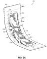
- FIGS. 2A-2C show an example inlet system 230 including an example engine cover 200 and an example internal ice protection member 210.
- FIGS. 2A and 2B show the engine cover 200 and the ice protection member 210, respectively, and
- FIG. 2C shows the inlet system 230 with the ice protection member 210 mounted on the engine cover 200.
- the inlet system 230, the engine cover 200, and the ice protection member 210 can be similar to the engine inlet 122, the engine cover 124, and the ice protection member 126 of FIG. 1B , respectively.
- the engine cover 200 includes a body 202 that is curved to cover a side-surfacing engine, e.g., in accordance with a contour of a fuselage of a rotorcraft.
- the body 202 can be made of stainless steel or any other suitable material.
- the body 202 defines an opening 204, e.g., in a middle of the engine cover 200.
- the opening 204 can also have a curved shape.
- Inside edges 203 and 205 of the body 202 define a front end and a back end of the opening 204.
- the front edge 203 of the body 202 is close to a front end of the rotorcraft and the back edge 205 of the body 202 is close to a back end of the rotorcraft.
- the rotorcraft moves forward, air flows backward from the front end of the rotorcraft to the back end of the rotorcraft and is sucked downstream through the opening 204 into the engine.
- the ice protection member 210 is configured to catch and hold ice with suction generated by an air flow into the engine to thus prevent ice with a particular size from entering into the engine.
- the particular size of the ice is larger than a size certified for the engine.
- the ice protection member 210 is also configured to minimize impact on engine performances.
- the ice protection member 210 can only partially cover the opening 204 of the engine cover 200 such that a percentage of the opening 204 remains open to allow enough air flow downstream into the engine for operation.
- the ice protection member 210 includes a mesh screen 212.
- the mesh screen 212 can be made of stainless steel or any other suitable material.
- the mesh screen 212 includes a number of pores each having a pore size, e.g., about 0.25 inch up to 0.50 inch. Edges of the mesh screen 212 can be kept thin.
- the ice protection member 210 can include a frame 214 surrounding the mesh screen 212, e.g., sealing around the edges of the mesh screen 212 to provide strength to the mesh screen and/or prevent the edges from harming people.
- the frame 214 can be made of fiberglass or any other suitable material.
- the ice protection member 210 includes a first part 216 and a second part 218 positioned with a folding angle ⁇ .
- the folding angle ⁇ can be 90 degree, an obtuse angle, or an acute angle.
- the first part 216 extends in a first direction from a back edge 205 of the ice protection member 210 (e.g., an intersection of the first part 216 and the second part 218) to a front edge 203 of the ice protection member 210.
- the second part 218 extends upwards in a second direction at an angle to the first direction, e.g., identical to the folding angle ⁇ .
- the first part 216 can catch and support ice on the mesh screen 212 and the second part 218 can catch and hold the ice on the mesh screen 212.
- the first part 216 is curved to accommodate a shape of the engine cover 200, e.g., along one or more folding lines 213 parallel to the first direction.
- the frame 214 can include wide portions 220 positioned in the second part 218 corresponding to the folding lines 213. The wide portions 220 provide strength to the mesh screen 212.
- FIC. 2C shows a perspective view of the example inlet system 230 when the ice protection member 210 is internally mounted on the engine cover 200.
- the edges of the body 202 of the engine cover 200 have a depth large enough for the ice protection member 210 to be internally mounted on and below the opening 204.
- the ice protection member 210 can be mounted onto the engine cover 200, e.g., by fastening the edges of the body 202 to the engine cover 200 with fasteners 221, e.g., pairs of blots and screws.
- the inlet system 230 can include one or more brackets 222 to hold the ice protection member 210, e.g., the first part 216, under the one or more folding lines 213.
- the brackets 222 can be fastened to the ice protection member 210, e.g., to the wide portions 220 in the second part 218, and further to the edges of the body 202 of the engine cover 200.
- the ice protection member 210 is sandwiched by the brackets 222 and the engine cover 200.
- the inlet system 230 is configured to endure a maximum pressure differential across the ice protection member 210, which can be equivalent to an ice blocked the mesh screen 212 to make one engine inoperative.
- the ice protection member 210 is mounted to partially cover the opening 204 of the engine cover 200 to keep a particular portion 224 of the opening 204 open.
- the perimeter of the open portion 224 is defined by inner edges of the engine cover 200, e.g., the front edge 203, and a front edge of the ice protection member 230, e.g., the frame 214.
- An area of the open portion 224 is separate from areas of open pores in the mesh screen 212.
- the mesh screen 212 covers a half of the opening 204 and thus the open portion 224 occupies another half of the opening 204.
- the mesh screen 212 can have a porosity ratio of about 70%.
- the area of the open pores of the mesh screen 212 is about 35% of an area of the opening 204
- an area of the open portion 224 is about 50% of the area of the opening 204
- the area of the open portion 224, together with the area of open pores of the mesh screen 212 is about 85% of the area of the opening 204.
- the area of the open portion 224 can be about 150 square inches. Keeping the portion 224 open enables the engine to suck enough amount of air into the engine for operation. Air can also be sucked into the engine through the open pores of the mesh screen 212, e.g., at a slower rate than air sucked through the open portion 224.
- the ice protection member 210 is configured to catch and hold ice and prevent large pieces of ice into the engine. During operation, air flows backward from the front end of the rotorcraft to the back end of the rotorcraft. Due to momentum, ice carried in the air flow stream tends to go to the back side of the engine inlet 230. Thus, to catch and hold the ice, the ice protection member 210 can be mounted closer to the back edge 205 of the engine cover 200 than to the front edge 203, thus the open portion 224 is closer to the front edge 203 of the engine cover 200 than to the back edge 205.
- the first part 216 of the ice protection member 210 extends forward in a first direction from the back edge 205 to the front edge 203 of the engine cover 200, and the second part 218 extends upward to the opening 204 of the engine cover 200 in a second direction with an angle to the first direction.
- the open portion 224 is left uncovered to provide space for air flow downstream.
- FIG. 2D shows a perspective view 250 of the example inlet system 230 mounted on an example rotorcraft, e.g., the rotorcraft 100 of FIGS. 1A-1B .
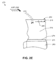
- FIG. 2E shows a schematic diagram showing a working principle of the example inlet system.
- the rotorcraft can include a side-facing engine 280, and the inlet system 230 can be a flush type engine inlet for the side-facing engine 280 and be mounted on a side surface of a fuselage 240 of the rotorcraft.
- the engine cover 200 of the inlet system 230 can be configured to accommodate a contour of the side surface of the fuselage 240, such that the engine cover 200 can be seamlessly assembled onto the fuselage 240, e.g., by fasteners 242.
- the engine cover 200 can be mounted below the side surface of the fuselage 240. As the ice protection member 210 is mounted below the opening 204 of the engine cover 200, the ice protection member 210 is positioned internally below the outside contour of the side surface of the fuselage 240.
- the ice protection member 210 can be configured to be far away from the engine 280, e.g., a compressor of the engine, to give air enough time to recover from a disturbance of going through the ice protection member 210.
- a depth from the first part 216 of the ice protection member 210 to the side surface of the fuselage 240 is controlled by a height of the second part 218 of the ice protection member 210.
- Water drops 262 and/or ice 264 can be sucked together with air through the inlet system 230.
- the water drops 262 hit the mesh screen 212 the water drops can freeze to ice.
- the ice can grow on the mesh screen 212, e.g., into an ice 266 with a larger size.
- the mesh screen 212 is configured to prevent ice with a size larger than a size certified for the engine 280 from entering into the engine 280.
- the mesh screen 212 has a number of pores each having a pore size, e.g., about 0.25 inch up to 0.50 inch in diameter.
- the pore size can be smaller than the certified size for the engine 280.
- the ice protection member 210 is configured to catch an ice with a particular size of about slightly wider than a half of the inlet opening 204. In a particular example, the ice protection member 210 is configured to catch the ice with about 9 inch long or with a size of about 9 inch by 3 inch by 0.375 inch.
- the folded ice protection member 210, together with the brackets 222 and the fasteners 221, can be configured to provide enough stiffness for the engine sucking the air and/or ice through the mesh screen 212 of the ice protection member 210.
- a filter 274 is used for the engine 280 to filter out contaminants such as dirt, salt water, ice, or the like that could be ingested into the engine.
- the filter can include a mesh screen that is made of fiber.
- the filter 274 is positioned below the opening 204 in the air flow passage 273 and between the ice protection member 210 and the front face 275 of the engine 280. In some implementations, the filter 274 is positioned close to the front face 275 of the engine 280 and cover the passage 273 to the engine 280.
- the filter 274 includes a monitor (not shown) for monitoring a contamination level on the filter 274.
- FIG. 3 is a flowchart of an example process 300 for configuring an inlet system having a passive internal ice protection member for an aircraft or rotorcraft having a gas turbine engine.
- the inlet system can be similar to the engine inlet 122 of FIG. 1B or the inlet system 230 of FIGS. 2C-2D .
- the ice protection member can be similar to the ice protection member 126 of FIG. 1B or the ice protection member 210 of FIGS. 2B-2D .
- a mesh screen is framed to form the ice protection member.
- the ice protection member is configured to catch and hold ice with a particular size larger than a size certified for the engine.
- the mesh screen can include a number of pores each having a pore size smaller than the certified ice size.
- the mesh screen can be made of stainless steel to prevent corrosion.
- the mesh screen can be framed at the edges of the mesh screen with fiberglass.
- the ice protection member includes a first part and a second part positioned with a folding angle, e.g., 90 degree. The first part can be folded along one or more folding lines to accommodate a shape of an engine cover.
- the second part can include wide portions of fiberglass to strength the mesh screen.
- the ice protection member is mounted on the engine cover to form the inlet system.
- the engine cover includes an opening, and an area of the ice protection member is smaller than an area of the opening.
- the ice protection member is configured to partially cover the opening such that a particular portion of the opening remains open.
- An area of the open portion, together with an area of porosity of the ice protection member, can be about 85% of the area of the opening of the engine cover.
- the ice protection member can be mounted to the engine cover by fastening the edges of the ice protection member to inner edges of the engine cover that are below the opening.
- One or more brackets can be used to support the ice protection member, e.g., to hold the first part of the ice protection member under the folding lines.
- the brackets can be fastened to the second part and further to the engine cover.
- the engine cover is mounted to cover the side-facing engine, such that the ice protection member is positioned between the opening of the engine cover and the engine.
- the engine cover is mounted on a side surface of the rotorcraft having a front end and a back end, and the ice protection member mounted on the engine cover is close to the back end of the rotorcraft and the open portion is close to the front end of the aircraft.
Landscapes
- Engineering & Computer Science (AREA)
- Chemical & Material Sciences (AREA)
- Combustion & Propulsion (AREA)
- Aviation & Aerospace Engineering (AREA)
- Mechanical Engineering (AREA)
- General Engineering & Computer Science (AREA)
- Body Structure For Vehicles (AREA)
Applications Claiming Priority (1)
| Application Number | Priority Date | Filing Date | Title |
|---|---|---|---|
| US14/947,325 US10036320B2 (en) | 2015-11-20 | 2015-11-20 | Passive internal ice protection systems for engine inlets |
Publications (2)
| Publication Number | Publication Date |
|---|---|
| EP3170751A1 true EP3170751A1 (de) | 2017-05-24 |
| EP3170751B1 EP3170751B1 (de) | 2018-03-14 |
Family
ID=56096461
Family Applications (1)
| Application Number | Title | Priority Date | Filing Date |
|---|---|---|---|
| EP16170623.9A Active EP3170751B1 (de) | 2015-11-20 | 2016-05-20 | Passive interne eisschutzsysteme für triebwerkseinlässe |
Country Status (2)
| Country | Link |
|---|---|
| US (2) | US10036320B2 (de) |
| EP (1) | EP3170751B1 (de) |
Cited By (2)
| Publication number | Priority date | Publication date | Assignee | Title |
|---|---|---|---|---|
| US10858995B2 (en) | 2015-11-20 | 2020-12-08 | Bell Helicopter Textron Inc. | Passive internal ice protection systems for engine inlets |
| FR3101613A1 (fr) * | 2019-10-07 | 2021-04-09 | Liebherr-Aerospace Toulouse Sas | Dispositif de protection d’un élément d’un système de conditionnement d’air contre un contact avec un objet indésirable |
Families Citing this family (8)
| Publication number | Priority date | Publication date | Assignee | Title |
|---|---|---|---|---|
| US10766628B2 (en) * | 2017-09-15 | 2020-09-08 | Bell Helicopter Textron Inc. | Air inlet with integrated structural hand hold |
| US10710732B2 (en) | 2017-09-15 | 2020-07-14 | Bell Helicopter Textron Inc. | Rotary aircraft ice protection system |
| US11634228B2 (en) * | 2017-11-01 | 2023-04-25 | Sikorsky Aircraft Corporation | High volume flow management of cooling air |
| US11525398B2 (en) * | 2019-04-02 | 2022-12-13 | The Boeing Company | Engine inlet with deployable particle separator |
| US11313277B2 (en) * | 2020-06-05 | 2022-04-26 | The Boeing Company | Auxiliary power unit plenum with a pleated screen for foreign object damage prevention |
| US12479587B2 (en) * | 2020-12-21 | 2025-11-25 | General Electric Company Polska Sp. Z O.O. | Skeleton screen for an air intake portion of a machine |
| FR3122406B1 (fr) * | 2021-04-28 | 2023-03-24 | Airbus Helicopters | giravion muni d’un système de contrôle du mouvement en lacet ayant un rotor caréné et une protection contre le givrage |
| WO2022256010A1 (en) * | 2021-06-03 | 2022-12-08 | Ptp Turbo Solutions, Llc. | Systems and methods associated with a removable inlet shield |
Citations (6)
| Publication number | Priority date | Publication date | Assignee | Title |
|---|---|---|---|---|
| US3421296A (en) * | 1966-11-15 | 1969-01-14 | United Aircraft Corp | Engine inlet air particle separator |
| US5697394A (en) * | 1993-03-02 | 1997-12-16 | United Technologies Corporation | Low observable engine air inlet system |
| WO2007090011A2 (en) * | 2006-01-30 | 2007-08-09 | Aerospace Filtration Systems, Inc. | Engine air intake barrier filter system for aircraft |
| EP2860113A1 (de) * | 2013-10-08 | 2015-04-15 | Bell Helicopter Textron Inc. | Motormontiertes Einlassplenum für ein Drehflügelflugzeug |
| EP2995556A1 (de) * | 2014-09-12 | 2016-03-16 | AIRBUS HELICOPTERS DEUTSCHLAND GmbH | Flugzeug mit Lufteinlass für ein Strahltriebwerk |
| EP3091211A1 (de) * | 2015-05-05 | 2016-11-09 | Bmc S.R.L. | Luftfahrzeug mit motor mit einem filter für die ansaugluft |
Family Cites Families (33)
| Publication number | Priority date | Publication date | Assignee | Title |
|---|---|---|---|---|
| US3124545A (en) | 1964-03-10 | Method of stabilizing cellular poly- | ||
| US2764390A (en) | 1954-04-01 | 1956-09-25 | Gen Electric | Anti-icing device |
| US3121545A (en) | 1962-01-10 | 1964-02-18 | John J Moss | Rotary deflector for aircraft engine intakes |
| US3196598A (en) * | 1962-10-31 | 1965-07-27 | Walter T Olson | Inlet deflector for jet engines |
| GB1137479A (en) | 1966-02-28 | 1968-12-18 | Mini Of Technology | Foreign body guards for aircraft |
| US3352104A (en) | 1966-06-27 | 1967-11-14 | Gen Motors Corp | Turbine inlet screen |
| US3449891A (en) * | 1966-11-15 | 1969-06-17 | United Aircraft Corp | Engine inlet air particle separator |
| US3483676A (en) | 1967-09-29 | 1969-12-16 | Gen Electric | Helicopter engine air inlets |
| US3871844A (en) | 1973-09-28 | 1975-03-18 | Sr Frank F Calvin | Screen apparatus for air inlet |
| US4561245A (en) | 1983-11-14 | 1985-12-31 | Atlantic Richfield Company | Turbine anti-icing system |
| US4688745A (en) | 1986-01-24 | 1987-08-25 | Rohr Industries, Inc. | Swirl anti-ice system |
| US4933546A (en) | 1988-08-23 | 1990-06-12 | Grumman Aerospace Corporation | Orifice ring ion beam neutralizer |
| US5029440A (en) | 1990-01-26 | 1991-07-09 | The United States Of America As Represented By The Secretary Of The Air Force | Acoustical anti-icing system |
| US5662292A (en) | 1995-05-03 | 1997-09-02 | Greene; Andrew T. | Helicopter engine filter system |
| US6267328B1 (en) | 1999-10-21 | 2001-07-31 | Rohr, Inc. | Hot air injection for swirling rotational anti-icing system |
| US6595742B2 (en) | 2000-10-02 | 2003-07-22 | Westar Corporation | Aircraft engine air filter and method |
| US7192462B2 (en) * | 2004-04-14 | 2007-03-20 | Aerospace Filtration Systems, Inc. | Engine air filter and sealing system |
| US7246480B2 (en) | 2004-11-04 | 2007-07-24 | Siemens Power Generation, Inc. | System for heating an air intake of turbine engine |
| US7575014B2 (en) * | 2005-07-29 | 2009-08-18 | Aerospace Filtration Systems, Inc. | Control of engine intake door |
| GB2429937A (en) | 2005-09-08 | 2007-03-14 | Siemens Ind Turbomachinery Ltd | Apparatus for mixing gas streams |
| US8439295B2 (en) * | 2006-07-14 | 2013-05-14 | Aerospace Filtration Systems, Inc. | Aircraft engine inlet pivotable barrier filter |
| US8049147B2 (en) | 2008-03-28 | 2011-11-01 | United Technologies Corporation | Engine inlet ice protection system with power control by zone |
| US7938368B2 (en) | 2008-04-07 | 2011-05-10 | United Technologies Corporation | Nosecone ice protection system for a gas turbine engine |
| WO2010077241A1 (en) * | 2008-12-30 | 2010-07-08 | Sikorsky Aircraft Corporation | Engine air particle separator |
| US8246291B2 (en) | 2009-05-21 | 2012-08-21 | Rolls-Royce Corporation | Thermal system for a working member of a power plant |
| US7871455B1 (en) | 2009-06-19 | 2011-01-18 | Vintage Capital Group, Llc | Jet engine protection system |
| US8973650B2 (en) | 2010-07-20 | 2015-03-10 | General Electric Company | Superconductive heat transfer system |
| US20120241561A1 (en) | 2011-03-24 | 2012-09-27 | Cox & Company, Inc. | Method and apparatus for protecting aircraft and aircraft engines against icing |
| US8819937B2 (en) * | 2011-05-16 | 2014-09-02 | Hamilton Sundstrand Corporation | Auxiliary power unit inlet duct screen assembly |
| US8961634B2 (en) * | 2011-10-17 | 2015-02-24 | Aerospace Filtration Systems, Inc. | Filter systems for air intakes of aircraft engines and related methods |
| FR2993862B1 (fr) | 2012-07-30 | 2015-08-21 | Turbomeca | Entree d'air pour moteur d'helicoptere a circulation de contournement augmentee |
| US20140260127A1 (en) * | 2013-03-15 | 2014-09-18 | Aerospace Filtration Systems, Inc. | Interchangeable inlet protection systems for air intakes of aircraft engines and related method |
| US10036320B2 (en) | 2015-11-20 | 2018-07-31 | Bell Helicopter Textron Inc. | Passive internal ice protection systems for engine inlets |
-
2015
- 2015-11-20 US US14/947,325 patent/US10036320B2/en active Active
-
2016
- 2016-05-20 EP EP16170623.9A patent/EP3170751B1/de active Active
-
2018
- 2018-06-22 US US16/016,159 patent/US10858995B2/en active Active
Patent Citations (6)
| Publication number | Priority date | Publication date | Assignee | Title |
|---|---|---|---|---|
| US3421296A (en) * | 1966-11-15 | 1969-01-14 | United Aircraft Corp | Engine inlet air particle separator |
| US5697394A (en) * | 1993-03-02 | 1997-12-16 | United Technologies Corporation | Low observable engine air inlet system |
| WO2007090011A2 (en) * | 2006-01-30 | 2007-08-09 | Aerospace Filtration Systems, Inc. | Engine air intake barrier filter system for aircraft |
| EP2860113A1 (de) * | 2013-10-08 | 2015-04-15 | Bell Helicopter Textron Inc. | Motormontiertes Einlassplenum für ein Drehflügelflugzeug |
| EP2995556A1 (de) * | 2014-09-12 | 2016-03-16 | AIRBUS HELICOPTERS DEUTSCHLAND GmbH | Flugzeug mit Lufteinlass für ein Strahltriebwerk |
| EP3091211A1 (de) * | 2015-05-05 | 2016-11-09 | Bmc S.R.L. | Luftfahrzeug mit motor mit einem filter für die ansaugluft |
Cited By (2)
| Publication number | Priority date | Publication date | Assignee | Title |
|---|---|---|---|---|
| US10858995B2 (en) | 2015-11-20 | 2020-12-08 | Bell Helicopter Textron Inc. | Passive internal ice protection systems for engine inlets |
| FR3101613A1 (fr) * | 2019-10-07 | 2021-04-09 | Liebherr-Aerospace Toulouse Sas | Dispositif de protection d’un élément d’un système de conditionnement d’air contre un contact avec un objet indésirable |
Also Published As
| Publication number | Publication date |
|---|---|
| EP3170751B1 (de) | 2018-03-14 |
| US20170145919A1 (en) | 2017-05-25 |
| US20180298818A1 (en) | 2018-10-18 |
| US10858995B2 (en) | 2020-12-08 |
| US10036320B2 (en) | 2018-07-31 |
Similar Documents
| Publication | Publication Date | Title |
|---|---|---|
| US10858995B2 (en) | Passive internal ice protection systems for engine inlets | |
| US6595742B2 (en) | Aircraft engine air filter and method | |
| US9340295B2 (en) | Inlet duct screen assembly | |
| US8512450B2 (en) | Engine air particle separator | |
| US20180334255A1 (en) | Weeping ferrofluid anti-ice system | |
| US9517842B2 (en) | Filters for aircraft engine inlets | |
| US6592078B2 (en) | Process for de-icing an air intake cowling of a reaction motor and device for practicing the same | |
| US9067679B2 (en) | Heated screen for air intake of aircraft engines | |
| US5662292A (en) | Helicopter engine filter system | |
| US20120292441A1 (en) | System and method for reducing the noise of pusher type aircraft propellers | |
| US9637240B2 (en) | Aircraft powerplant | |
| US20050229558A1 (en) | Engine air filter and sealing system | |
| EP2484587A1 (de) | Kipprotorflugzeug mit fester Motoranordnung | |
| EP2860113B1 (de) | Motormontiertes Einlassplenum für ein Drehflügelflugzeug | |
| US20090194633A1 (en) | Icing protection for aircraft air inlet scoops | |
| FR3083520A1 (fr) | Aéronef | |
| EP2886453B1 (de) | System für Grenzschichtsteuerung und Flugzeug mit dem Grenzschichtsteuersystem | |
| CN104703878A (zh) | 具有形成层流边界层流动的系统的飞机机翼 | |
| EP3594124A1 (de) | Eisschutzsystem für ein bauteil eines aerodynamischen systems | |
| EP3090941B1 (de) | Optimiertes gondelprofil und optimierte kammerform für grenzschichtaufnahmeaktive laminare strömungssteuerung | |
| EP3556661B1 (de) | Triebwerkseinlasssystem mit integrierter feuerschutzwanddichtung | |
| US20160144967A1 (en) | Integrated pusher turbofan for aircraft | |
| US9988148B2 (en) | Vehicle with asymmetric nacelle configuration | |
| EP3031720B1 (de) | Leitflügel für einen schiebepropeller für ein drehflügelflugzeug | |
| UA28455U (en) | Vertical take-off and landing flight vehicle |
Legal Events
| Date | Code | Title | Description |
|---|---|---|---|
| PUAI | Public reference made under article 153(3) epc to a published international application that has entered the european phase |
Free format text: ORIGINAL CODE: 0009012 |
|
| 17P | Request for examination filed |
Effective date: 20160520 |
|
| AK | Designated contracting states |
Kind code of ref document: A1 Designated state(s): AL AT BE BG CH CY CZ DE DK EE ES FI FR GB GR HR HU IE IS IT LI LT LU LV MC MK MT NL NO PL PT RO RS SE SI SK SM TR |
|
| AX | Request for extension of the european patent |
Extension state: BA ME |
|
| RIC1 | Information provided on ipc code assigned before grant |
Ipc: B64C 27/06 20060101ALI20171017BHEP Ipc: B64D 33/02 20060101ALI20171017BHEP Ipc: B64D 27/14 20060101AFI20171017BHEP Ipc: F02C 7/055 20060101ALI20171017BHEP |
|
| GRAP | Despatch of communication of intention to grant a patent |
Free format text: ORIGINAL CODE: EPIDOSNIGR1 |
|
| INTG | Intention to grant announced |
Effective date: 20171211 |
|
| GRAS | Grant fee paid |
Free format text: ORIGINAL CODE: EPIDOSNIGR3 |
|
| GRAA | (expected) grant |
Free format text: ORIGINAL CODE: 0009210 |
|
| AK | Designated contracting states |
Kind code of ref document: B1 Designated state(s): AL AT BE BG CH CY CZ DE DK EE ES FI FR GB GR HR HU IE IS IT LI LT LU LV MC MK MT NL NO PL PT RO RS SE SI SK SM TR |
|
| REG | Reference to a national code |
Ref country code: GB Ref legal event code: FG4D |
|
| REG | Reference to a national code |
Ref country code: CH Ref legal event code: EP Ref country code: AT Ref legal event code: REF Ref document number: 978634 Country of ref document: AT Kind code of ref document: T Effective date: 20180315 |
|
| REG | Reference to a national code |
Ref country code: IE Ref legal event code: FG4D |
|
| REG | Reference to a national code |
Ref country code: DE Ref legal event code: R096 Ref document number: 602016001957 Country of ref document: DE |
|
| REG | Reference to a national code |
Ref country code: FR Ref legal event code: PLFP Year of fee payment: 3 |
|
| REG | Reference to a national code |
Ref country code: NL Ref legal event code: MP Effective date: 20180314 |
|
| REG | Reference to a national code |
Ref country code: LT Ref legal event code: MG4D |
|
| PG25 | Lapsed in a contracting state [announced via postgrant information from national office to epo] |
Ref country code: FI Free format text: LAPSE BECAUSE OF FAILURE TO SUBMIT A TRANSLATION OF THE DESCRIPTION OR TO PAY THE FEE WITHIN THE PRESCRIBED TIME-LIMIT Effective date: 20180314 Ref country code: LT Free format text: LAPSE BECAUSE OF FAILURE TO SUBMIT A TRANSLATION OF THE DESCRIPTION OR TO PAY THE FEE WITHIN THE PRESCRIBED TIME-LIMIT Effective date: 20180314 Ref country code: NO Free format text: LAPSE BECAUSE OF FAILURE TO SUBMIT A TRANSLATION OF THE DESCRIPTION OR TO PAY THE FEE WITHIN THE PRESCRIBED TIME-LIMIT Effective date: 20180614 Ref country code: HR Free format text: LAPSE BECAUSE OF FAILURE TO SUBMIT A TRANSLATION OF THE DESCRIPTION OR TO PAY THE FEE WITHIN THE PRESCRIBED TIME-LIMIT Effective date: 20180314 Ref country code: CY Free format text: LAPSE BECAUSE OF FAILURE TO SUBMIT A TRANSLATION OF THE DESCRIPTION OR TO PAY THE FEE WITHIN THE PRESCRIBED TIME-LIMIT Effective date: 20180314 |
|
| REG | Reference to a national code |
Ref country code: AT Ref legal event code: MK05 Ref document number: 978634 Country of ref document: AT Kind code of ref document: T Effective date: 20180314 |
|
| PG25 | Lapsed in a contracting state [announced via postgrant information from national office to epo] |
Ref country code: RS Free format text: LAPSE BECAUSE OF FAILURE TO SUBMIT A TRANSLATION OF THE DESCRIPTION OR TO PAY THE FEE WITHIN THE PRESCRIBED TIME-LIMIT Effective date: 20180314 Ref country code: GR Free format text: LAPSE BECAUSE OF FAILURE TO SUBMIT A TRANSLATION OF THE DESCRIPTION OR TO PAY THE FEE WITHIN THE PRESCRIBED TIME-LIMIT Effective date: 20180615 Ref country code: LV Free format text: LAPSE BECAUSE OF FAILURE TO SUBMIT A TRANSLATION OF THE DESCRIPTION OR TO PAY THE FEE WITHIN THE PRESCRIBED TIME-LIMIT Effective date: 20180314 Ref country code: SE Free format text: LAPSE BECAUSE OF FAILURE TO SUBMIT A TRANSLATION OF THE DESCRIPTION OR TO PAY THE FEE WITHIN THE PRESCRIBED TIME-LIMIT Effective date: 20180314 Ref country code: BG Free format text: LAPSE BECAUSE OF FAILURE TO SUBMIT A TRANSLATION OF THE DESCRIPTION OR TO PAY THE FEE WITHIN THE PRESCRIBED TIME-LIMIT Effective date: 20180614 |
|
| PG25 | Lapsed in a contracting state [announced via postgrant information from national office to epo] |
Ref country code: AL Free format text: LAPSE BECAUSE OF FAILURE TO SUBMIT A TRANSLATION OF THE DESCRIPTION OR TO PAY THE FEE WITHIN THE PRESCRIBED TIME-LIMIT Effective date: 20180314 Ref country code: EE Free format text: LAPSE BECAUSE OF FAILURE TO SUBMIT A TRANSLATION OF THE DESCRIPTION OR TO PAY THE FEE WITHIN THE PRESCRIBED TIME-LIMIT Effective date: 20180314 Ref country code: RO Free format text: LAPSE BECAUSE OF FAILURE TO SUBMIT A TRANSLATION OF THE DESCRIPTION OR TO PAY THE FEE WITHIN THE PRESCRIBED TIME-LIMIT Effective date: 20180314 Ref country code: PL Free format text: LAPSE BECAUSE OF FAILURE TO SUBMIT A TRANSLATION OF THE DESCRIPTION OR TO PAY THE FEE WITHIN THE PRESCRIBED TIME-LIMIT Effective date: 20180314 Ref country code: NL Free format text: LAPSE BECAUSE OF FAILURE TO SUBMIT A TRANSLATION OF THE DESCRIPTION OR TO PAY THE FEE WITHIN THE PRESCRIBED TIME-LIMIT Effective date: 20180314 Ref country code: ES Free format text: LAPSE BECAUSE OF FAILURE TO SUBMIT A TRANSLATION OF THE DESCRIPTION OR TO PAY THE FEE WITHIN THE PRESCRIBED TIME-LIMIT Effective date: 20180314 |
|
| PG25 | Lapsed in a contracting state [announced via postgrant information from national office to epo] |
Ref country code: CZ Free format text: LAPSE BECAUSE OF FAILURE TO SUBMIT A TRANSLATION OF THE DESCRIPTION OR TO PAY THE FEE WITHIN THE PRESCRIBED TIME-LIMIT Effective date: 20180314 Ref country code: SK Free format text: LAPSE BECAUSE OF FAILURE TO SUBMIT A TRANSLATION OF THE DESCRIPTION OR TO PAY THE FEE WITHIN THE PRESCRIBED TIME-LIMIT Effective date: 20180314 Ref country code: AT Free format text: LAPSE BECAUSE OF FAILURE TO SUBMIT A TRANSLATION OF THE DESCRIPTION OR TO PAY THE FEE WITHIN THE PRESCRIBED TIME-LIMIT Effective date: 20180314 Ref country code: SM Free format text: LAPSE BECAUSE OF FAILURE TO SUBMIT A TRANSLATION OF THE DESCRIPTION OR TO PAY THE FEE WITHIN THE PRESCRIBED TIME-LIMIT Effective date: 20180314 |
|
| REG | Reference to a national code |
Ref country code: DE Ref legal event code: R097 Ref document number: 602016001957 Country of ref document: DE |
|
| PG25 | Lapsed in a contracting state [announced via postgrant information from national office to epo] |
Ref country code: PT Free format text: LAPSE BECAUSE OF FAILURE TO SUBMIT A TRANSLATION OF THE DESCRIPTION OR TO PAY THE FEE WITHIN THE PRESCRIBED TIME-LIMIT Effective date: 20180716 |
|
| PLBE | No opposition filed within time limit |
Free format text: ORIGINAL CODE: 0009261 |
|
| STAA | Information on the status of an ep patent application or granted ep patent |
Free format text: STATUS: NO OPPOSITION FILED WITHIN TIME LIMIT |
|
| REG | Reference to a national code |
Ref country code: BE Ref legal event code: MM Effective date: 20180531 |
|
| PG25 | Lapsed in a contracting state [announced via postgrant information from national office to epo] |
Ref country code: DK Free format text: LAPSE BECAUSE OF FAILURE TO SUBMIT A TRANSLATION OF THE DESCRIPTION OR TO PAY THE FEE WITHIN THE PRESCRIBED TIME-LIMIT Effective date: 20180314 Ref country code: MC Free format text: LAPSE BECAUSE OF FAILURE TO SUBMIT A TRANSLATION OF THE DESCRIPTION OR TO PAY THE FEE WITHIN THE PRESCRIBED TIME-LIMIT Effective date: 20180314 |
|
| 26N | No opposition filed |
Effective date: 20181217 |
|
| REG | Reference to a national code |
Ref country code: IE Ref legal event code: MM4A |
|
| PG25 | Lapsed in a contracting state [announced via postgrant information from national office to epo] |
Ref country code: LU Free format text: LAPSE BECAUSE OF NON-PAYMENT OF DUE FEES Effective date: 20180520 |
|
| PG25 | Lapsed in a contracting state [announced via postgrant information from national office to epo] |
Ref country code: IE Free format text: LAPSE BECAUSE OF NON-PAYMENT OF DUE FEES Effective date: 20180520 |
|
| PG25 | Lapsed in a contracting state [announced via postgrant information from national office to epo] |
Ref country code: BE Free format text: LAPSE BECAUSE OF NON-PAYMENT OF DUE FEES Effective date: 20180531 |
|
| REG | Reference to a national code |
Ref country code: CH Ref legal event code: PL |
|
| PG25 | Lapsed in a contracting state [announced via postgrant information from national office to epo] |
Ref country code: CH Free format text: LAPSE BECAUSE OF NON-PAYMENT OF DUE FEES Effective date: 20190531 Ref country code: LI Free format text: LAPSE BECAUSE OF NON-PAYMENT OF DUE FEES Effective date: 20190531 Ref country code: MT Free format text: LAPSE BECAUSE OF NON-PAYMENT OF DUE FEES Effective date: 20180520 |
|
| PG25 | Lapsed in a contracting state [announced via postgrant information from national office to epo] |
Ref country code: TR Free format text: LAPSE BECAUSE OF FAILURE TO SUBMIT A TRANSLATION OF THE DESCRIPTION OR TO PAY THE FEE WITHIN THE PRESCRIBED TIME-LIMIT Effective date: 20180314 |
|
| PG25 | Lapsed in a contracting state [announced via postgrant information from national office to epo] |
Ref country code: HU Free format text: LAPSE BECAUSE OF FAILURE TO SUBMIT A TRANSLATION OF THE DESCRIPTION OR TO PAY THE FEE WITHIN THE PRESCRIBED TIME-LIMIT; INVALID AB INITIO Effective date: 20160520 Ref country code: MK Free format text: LAPSE BECAUSE OF NON-PAYMENT OF DUE FEES Effective date: 20180314 |
|
| PG25 | Lapsed in a contracting state [announced via postgrant information from national office to epo] |
Ref country code: IS Free format text: LAPSE BECAUSE OF FAILURE TO SUBMIT A TRANSLATION OF THE DESCRIPTION OR TO PAY THE FEE WITHIN THE PRESCRIBED TIME-LIMIT Effective date: 20180714 |
|
| PG25 | Lapsed in a contracting state [announced via postgrant information from national office to epo] |
Ref country code: SI Free format text: LAPSE BECAUSE OF NON-PAYMENT OF DUE FEES Effective date: 20180520 |
|
| P01 | Opt-out of the competence of the unified patent court (upc) registered |
Effective date: 20230602 |
|
| PGFP | Annual fee paid to national office [announced via postgrant information from national office to epo] |
Ref country code: DE Payment date: 20250529 Year of fee payment: 10 |
|
| PGFP | Annual fee paid to national office [announced via postgrant information from national office to epo] |
Ref country code: GB Payment date: 20250527 Year of fee payment: 10 |
|
| PGFP | Annual fee paid to national office [announced via postgrant information from national office to epo] |
Ref country code: IT Payment date: 20250521 Year of fee payment: 10 |
|
| PGFP | Annual fee paid to national office [announced via postgrant information from national office to epo] |
Ref country code: FR Payment date: 20250526 Year of fee payment: 10 |