EP3170691A2 - Apparatus and method of preventing over-discharge of vehicle battery - Google Patents
Apparatus and method of preventing over-discharge of vehicle battery Download PDFInfo
- Publication number
- EP3170691A2 EP3170691A2 EP16175405.6A EP16175405A EP3170691A2 EP 3170691 A2 EP3170691 A2 EP 3170691A2 EP 16175405 A EP16175405 A EP 16175405A EP 3170691 A2 EP3170691 A2 EP 3170691A2
- Authority
- EP
- European Patent Office
- Prior art keywords
- battery
- relay
- discharge
- vehicle
- controller
- Prior art date
- Legal status (The legal status is an assumption and is not a legal conclusion. Google has not performed a legal analysis and makes no representation as to the accuracy of the status listed.)
- Granted
Links
Images
Classifications
-
- B—PERFORMING OPERATIONS; TRANSPORTING
- B60—VEHICLES IN GENERAL
- B60R—VEHICLES, VEHICLE FITTINGS, OR VEHICLE PARTS, NOT OTHERWISE PROVIDED FOR
- B60R16/00—Electric or fluid circuits specially adapted for vehicles and not otherwise provided for; Arrangement of elements of electric or fluid circuits specially adapted for vehicles and not otherwise provided for
- B60R16/02—Electric or fluid circuits specially adapted for vehicles and not otherwise provided for; Arrangement of elements of electric or fluid circuits specially adapted for vehicles and not otherwise provided for electric constitutive elements
- B60R16/023—Electric or fluid circuits specially adapted for vehicles and not otherwise provided for; Arrangement of elements of electric or fluid circuits specially adapted for vehicles and not otherwise provided for electric constitutive elements for transmission of signals between vehicle parts or subsystems
-
- B—PERFORMING OPERATIONS; TRANSPORTING
- B60—VEHICLES IN GENERAL
- B60L—PROPULSION OF ELECTRICALLY-PROPELLED VEHICLES; SUPPLYING ELECTRIC POWER FOR AUXILIARY EQUIPMENT OF ELECTRICALLY-PROPELLED VEHICLES; ELECTRODYNAMIC BRAKE SYSTEMS FOR VEHICLES IN GENERAL; MAGNETIC SUSPENSION OR LEVITATION FOR VEHICLES; MONITORING OPERATING VARIABLES OF ELECTRICALLY-PROPELLED VEHICLES; ELECTRIC SAFETY DEVICES FOR ELECTRICALLY-PROPELLED VEHICLES
- B60L3/00—Electric devices on electrically-propelled vehicles for safety purposes; Monitoring operating variables, e.g. speed, deceleration or energy consumption
- B60L3/04—Cutting off the power supply under fault conditions
-
- B—PERFORMING OPERATIONS; TRANSPORTING
- B60—VEHICLES IN GENERAL
- B60L—PROPULSION OF ELECTRICALLY-PROPELLED VEHICLES; SUPPLYING ELECTRIC POWER FOR AUXILIARY EQUIPMENT OF ELECTRICALLY-PROPELLED VEHICLES; ELECTRODYNAMIC BRAKE SYSTEMS FOR VEHICLES IN GENERAL; MAGNETIC SUSPENSION OR LEVITATION FOR VEHICLES; MONITORING OPERATING VARIABLES OF ELECTRICALLY-PROPELLED VEHICLES; ELECTRIC SAFETY DEVICES FOR ELECTRICALLY-PROPELLED VEHICLES
- B60L1/00—Supplying electric power to auxiliary equipment of vehicles
- B60L1/003—Supplying electric power to auxiliary equipment of vehicles to auxiliary motors, e.g. for pumps, compressors
-
- B—PERFORMING OPERATIONS; TRANSPORTING
- B60—VEHICLES IN GENERAL
- B60L—PROPULSION OF ELECTRICALLY-PROPELLED VEHICLES; SUPPLYING ELECTRIC POWER FOR AUXILIARY EQUIPMENT OF ELECTRICALLY-PROPELLED VEHICLES; ELECTRODYNAMIC BRAKE SYSTEMS FOR VEHICLES IN GENERAL; MAGNETIC SUSPENSION OR LEVITATION FOR VEHICLES; MONITORING OPERATING VARIABLES OF ELECTRICALLY-PROPELLED VEHICLES; ELECTRIC SAFETY DEVICES FOR ELECTRICALLY-PROPELLED VEHICLES
- B60L3/00—Electric devices on electrically-propelled vehicles for safety purposes; Monitoring operating variables, e.g. speed, deceleration or energy consumption
- B60L3/0023—Detecting, eliminating, remedying or compensating for drive train abnormalities, e.g. failures within the drive train
- B60L3/0046—Detecting, eliminating, remedying or compensating for drive train abnormalities, e.g. failures within the drive train relating to electric energy storage systems, e.g. batteries or capacitors
-
- B—PERFORMING OPERATIONS; TRANSPORTING
- B60—VEHICLES IN GENERAL
- B60L—PROPULSION OF ELECTRICALLY-PROPELLED VEHICLES; SUPPLYING ELECTRIC POWER FOR AUXILIARY EQUIPMENT OF ELECTRICALLY-PROPELLED VEHICLES; ELECTRODYNAMIC BRAKE SYSTEMS FOR VEHICLES IN GENERAL; MAGNETIC SUSPENSION OR LEVITATION FOR VEHICLES; MONITORING OPERATING VARIABLES OF ELECTRICALLY-PROPELLED VEHICLES; ELECTRIC SAFETY DEVICES FOR ELECTRICALLY-PROPELLED VEHICLES
- B60L3/00—Electric devices on electrically-propelled vehicles for safety purposes; Monitoring operating variables, e.g. speed, deceleration or energy consumption
- B60L3/0023—Detecting, eliminating, remedying or compensating for drive train abnormalities, e.g. failures within the drive train
- B60L3/0084—Detecting, eliminating, remedying or compensating for drive train abnormalities, e.g. failures within the drive train relating to control modules
-
- B—PERFORMING OPERATIONS; TRANSPORTING
- B60—VEHICLES IN GENERAL
- B60L—PROPULSION OF ELECTRICALLY-PROPELLED VEHICLES; SUPPLYING ELECTRIC POWER FOR AUXILIARY EQUIPMENT OF ELECTRICALLY-PROPELLED VEHICLES; ELECTRODYNAMIC BRAKE SYSTEMS FOR VEHICLES IN GENERAL; MAGNETIC SUSPENSION OR LEVITATION FOR VEHICLES; MONITORING OPERATING VARIABLES OF ELECTRICALLY-PROPELLED VEHICLES; ELECTRIC SAFETY DEVICES FOR ELECTRICALLY-PROPELLED VEHICLES
- B60L3/00—Electric devices on electrically-propelled vehicles for safety purposes; Monitoring operating variables, e.g. speed, deceleration or energy consumption
- B60L3/12—Recording operating variables ; Monitoring of operating variables
-
- B—PERFORMING OPERATIONS; TRANSPORTING
- B60—VEHICLES IN GENERAL
- B60L—PROPULSION OF ELECTRICALLY-PROPELLED VEHICLES; SUPPLYING ELECTRIC POWER FOR AUXILIARY EQUIPMENT OF ELECTRICALLY-PROPELLED VEHICLES; ELECTRODYNAMIC BRAKE SYSTEMS FOR VEHICLES IN GENERAL; MAGNETIC SUSPENSION OR LEVITATION FOR VEHICLES; MONITORING OPERATING VARIABLES OF ELECTRICALLY-PROPELLED VEHICLES; ELECTRIC SAFETY DEVICES FOR ELECTRICALLY-PROPELLED VEHICLES
- B60L58/00—Methods or circuit arrangements for monitoring or controlling batteries or fuel cells, specially adapted for electric vehicles
- B60L58/10—Methods or circuit arrangements for monitoring or controlling batteries or fuel cells, specially adapted for electric vehicles for monitoring or controlling batteries
- B60L58/12—Methods or circuit arrangements for monitoring or controlling batteries or fuel cells, specially adapted for electric vehicles for monitoring or controlling batteries responding to state of charge [SoC]
- B60L58/14—Preventing excessive discharging
-
- B—PERFORMING OPERATIONS; TRANSPORTING
- B60—VEHICLES IN GENERAL
- B60R—VEHICLES, VEHICLE FITTINGS, OR VEHICLE PARTS, NOT OTHERWISE PROVIDED FOR
- B60R16/00—Electric or fluid circuits specially adapted for vehicles and not otherwise provided for; Arrangement of elements of electric or fluid circuits specially adapted for vehicles and not otherwise provided for
- B60R16/02—Electric or fluid circuits specially adapted for vehicles and not otherwise provided for; Arrangement of elements of electric or fluid circuits specially adapted for vehicles and not otherwise provided for electric constitutive elements
- B60R16/03—Electric or fluid circuits specially adapted for vehicles and not otherwise provided for; Arrangement of elements of electric or fluid circuits specially adapted for vehicles and not otherwise provided for electric constitutive elements for supply of electrical power to vehicle subsystems or for
- B60R16/033—Electric or fluid circuits specially adapted for vehicles and not otherwise provided for; Arrangement of elements of electric or fluid circuits specially adapted for vehicles and not otherwise provided for electric constitutive elements for supply of electrical power to vehicle subsystems or for characterised by the use of electrical cells or batteries
-
- H—ELECTRICITY
- H01—ELECTRIC ELEMENTS
- H01H—ELECTRIC SWITCHES; RELAYS; SELECTORS; EMERGENCY PROTECTIVE DEVICES
- H01H47/00—Circuit arrangements not adapted to a particular application of the relay and designed to obtain desired operating characteristics or to provide energising current
- H01H47/002—Monitoring or fail-safe circuits
-
- H—ELECTRICITY
- H02—GENERATION; CONVERSION OR DISTRIBUTION OF ELECTRIC POWER
- H02H—EMERGENCY PROTECTIVE CIRCUIT ARRANGEMENTS
- H02H7/00—Emergency protective circuit arrangements specially adapted for specific types of electric machines or apparatus or for sectionalised protection of cable or line systems, and effecting automatic switching in the event of an undesired change from normal working conditions
- H02H7/18—Emergency protective circuit arrangements specially adapted for specific types of electric machines or apparatus or for sectionalised protection of cable or line systems, and effecting automatic switching in the event of an undesired change from normal working conditions for batteries; for accumulators
-
- H—ELECTRICITY
- H02—GENERATION; CONVERSION OR DISTRIBUTION OF ELECTRIC POWER
- H02H—EMERGENCY PROTECTIVE CIRCUIT ARRANGEMENTS
- H02H7/00—Emergency protective circuit arrangements specially adapted for specific types of electric machines or apparatus or for sectionalised protection of cable or line systems, and effecting automatic switching in the event of an undesired change from normal working conditions
- H02H7/20—Emergency protective circuit arrangements specially adapted for specific types of electric machines or apparatus or for sectionalised protection of cable or line systems, and effecting automatic switching in the event of an undesired change from normal working conditions for electronic equipment
-
- H—ELECTRICITY
- H02—GENERATION; CONVERSION OR DISTRIBUTION OF ELECTRIC POWER
- H02J—ELECTRIC POWER NETWORKS; CIRCUIT ARRANGEMENTS OR SYSTEMS FOR SUPPLYING OR DISTRIBUTING ELECTRIC POWER; SYSTEMS FOR STORING ELECTRIC ENERGY
- H02J7/00—Circuit arrangements for charging or discharging batteries or for supplying loads from batteries
- H02J7/60—Circuit arrangements for charging or discharging batteries or for supplying loads from batteries including safety or protection arrangements
- H02J7/663—Circuit arrangements for charging or discharging batteries or for supplying loads from batteries including safety or protection arrangements using battery or load disconnect circuits
-
- B—PERFORMING OPERATIONS; TRANSPORTING
- B60—VEHICLES IN GENERAL
- B60L—PROPULSION OF ELECTRICALLY-PROPELLED VEHICLES; SUPPLYING ELECTRIC POWER FOR AUXILIARY EQUIPMENT OF ELECTRICALLY-PROPELLED VEHICLES; ELECTRODYNAMIC BRAKE SYSTEMS FOR VEHICLES IN GENERAL; MAGNETIC SUSPENSION OR LEVITATION FOR VEHICLES; MONITORING OPERATING VARIABLES OF ELECTRICALLY-PROPELLED VEHICLES; ELECTRIC SAFETY DEVICES FOR ELECTRICALLY-PROPELLED VEHICLES
- B60L2240/00—Control parameters of input or output; Target parameters
- B60L2240/40—Drive Train control parameters
- B60L2240/54—Drive Train control parameters related to batteries
- B60L2240/547—Voltage
-
- B—PERFORMING OPERATIONS; TRANSPORTING
- B60—VEHICLES IN GENERAL
- B60L—PROPULSION OF ELECTRICALLY-PROPELLED VEHICLES; SUPPLYING ELECTRIC POWER FOR AUXILIARY EQUIPMENT OF ELECTRICALLY-PROPELLED VEHICLES; ELECTRODYNAMIC BRAKE SYSTEMS FOR VEHICLES IN GENERAL; MAGNETIC SUSPENSION OR LEVITATION FOR VEHICLES; MONITORING OPERATING VARIABLES OF ELECTRICALLY-PROPELLED VEHICLES; ELECTRIC SAFETY DEVICES FOR ELECTRICALLY-PROPELLED VEHICLES
- B60L2250/00—Driver interactions
- B60L2250/10—Driver interactions by alarm
-
- H—ELECTRICITY
- H02—GENERATION; CONVERSION OR DISTRIBUTION OF ELECTRIC POWER
- H02J—ELECTRIC POWER NETWORKS; CIRCUIT ARRANGEMENTS OR SYSTEMS FOR SUPPLYING OR DISTRIBUTING ELECTRIC POWER; SYSTEMS FOR STORING ELECTRIC ENERGY
- H02J7/00—Circuit arrangements for charging or discharging batteries or for supplying loads from batteries
- H02J7/60—Circuit arrangements for charging or discharging batteries or for supplying loads from batteries including safety or protection arrangements
- H02J7/63—Circuit arrangements for charging or discharging batteries or for supplying loads from batteries including safety or protection arrangements against overdischarge
-
- Y—GENERAL TAGGING OF NEW TECHNOLOGICAL DEVELOPMENTS; GENERAL TAGGING OF CROSS-SECTIONAL TECHNOLOGIES SPANNING OVER SEVERAL SECTIONS OF THE IPC; TECHNICAL SUBJECTS COVERED BY FORMER USPC CROSS-REFERENCE ART COLLECTIONS [XRACs] AND DIGESTS
- Y02—TECHNOLOGIES OR APPLICATIONS FOR MITIGATION OR ADAPTATION AGAINST CLIMATE CHANGE
- Y02T—CLIMATE CHANGE MITIGATION TECHNOLOGIES RELATED TO TRANSPORTATION
- Y02T10/00—Road transport of goods or passengers
- Y02T10/60—Other road transportation technologies with climate change mitigation effect
- Y02T10/70—Energy storage systems for electromobility, e.g. batteries
-
- Y—GENERAL TAGGING OF NEW TECHNOLOGICAL DEVELOPMENTS; GENERAL TAGGING OF CROSS-SECTIONAL TECHNOLOGIES SPANNING OVER SEVERAL SECTIONS OF THE IPC; TECHNICAL SUBJECTS COVERED BY FORMER USPC CROSS-REFERENCE ART COLLECTIONS [XRACs] AND DIGESTS
- Y10—TECHNICAL SUBJECTS COVERED BY FORMER USPC
- Y10S—TECHNICAL SUBJECTS COVERED BY FORMER USPC CROSS-REFERENCE ART COLLECTIONS [XRACs] AND DIGESTS
- Y10S903/00—Hybrid electric vehicles, HEVS
- Y10S903/902—Prime movers comprising electrical and internal combustion motors
- Y10S903/903—Prime movers comprising electrical and internal combustion motors having energy storing means, e.g. battery, capacitor
- Y10S903/904—Component specially adapted for hev
- Y10S903/907—Electricity storage, e.g. battery, capacitor
Definitions
- the present disclosure relates to an apparatus and a method of preventing over-discharge of a vehicle battery, and more particularly, to a technology of protecting controllers as well as a battery (for example, a lithium ion battery of 12V) supplying power to electric loads of a vehicle by controlling shut-off sequences of the controllers in the vehicle to be performed at the time of turning off a relay for preventing over-discharge of a lithium ion battery.
- a battery for example, a lithium ion battery of 12V
- a vehicle includes a high voltage battery for supplying driving power and an auxiliary battery for supplying operation power to an internal electrical apparatus (an electric load).
- a low voltage direct current (DC) to DC converter (LDC) connected to the auxiliary battery and the electrical apparatus down-converts a high voltage of the high voltage battery into a voltage for charging the auxiliary battery when a voltage of the auxiliary battery does not exceed a reference value under a control of a higher controller.
- the auxiliary battery serves to supply operation power to electrical apparatus such as lamps, systems, electronic control units (ECUs), and the like, as well as for starting the vehicle.
- electrical apparatus such as lamps, systems, electronic control units (ECUs), and the like, as well as for starting the vehicle.
- Lead-acid storage batteries have been mainly used as the auxiliary battery of a vehicle since lead-acid may be recharged and be used even though they are completely discharged.
- a lead-acid storage battery is heavy and has a low charging density, and lead-acid used in the lead-acid storage battery may have adverse environmental effects. Therefore, the lead-acid storage battery has been replaced by a lithium ion battery in an some vehicles.
- An aspect of the present disclosure provides an apparatus and a method of preventing over-discharge of a battery for a vehicle capable of safely protecting the respective controllers in the vehicle as well as a battery (for example, a lithium ion battery of 12V) supplying power to electric loads of the vehicle by controlling shut-off sequences of the respective controllers in the vehicle to be performed at the time of turning off a relay for preventing over-discharge of the lithium ion battery of 12V.
- a battery for example, a lithium ion battery of 12V
- an apparatus of preventing over-discharge of a battery for a vehicle may include: a voltage sensor for sensing a voltage of the battery; a relay for preventing the over-discharge of the battery; a power state sensor for sensing an ignition on state; and a controller for outputting a warning message when the voltage of the battery becomes a first threshold value in the ignition on state and turning off the relay after transmitting shut-off commands to the respective electronic control units (ECUs) through a vehicle network when the voltage of the battery becomes a second threshold value.
- ECUs electronice control units
- a method of preventing over-discharge of a battery for a vehicle may include: sensing an ignition on state by a power state sensor; sensing a voltage of the battery by a voltage sensor; outputting a warning message by a controller when the voltage of the battery becomes a first threshold value in the ignition on state; transmitting shut-off commands to the respective ECUs through a vehicle network by the controller when the voltage of the battery becomes a second threshold value; and turning off a relay for preventing the over-discharge of the battery by the controller.
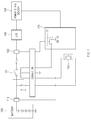
- FIG. 1 is a block diagram illustrating an apparatus of preventing over-discharge of a vehicle battery according to an exemplary embodiment of the present disclosure.
- an apparatus of preventing over-discharge of a battery for a vehicle may include a battery 100, a voltage sensor 110, a relay 120, a current sensor 130, an engine room junction box (J/B) 140, a power state sensor 150, a switch 160, a controller 170, and the like.
- a battery 100 a voltage sensor 110, a relay 120, a current sensor 130, an engine room junction box (J/B) 140, a power state sensor 150, a switch 160, a controller 170, and the like.
- J/B engine room junction box
- the battery 100 which may be a lithium ion battery of 12V (a low-voltage auxiliary battery), supplies power required for electric loads of the vehicle.
- the battery 100 may also be implemented by a lead-acid storage battery, or another type of battery.
- the voltage sensor 110 may sense a voltage of the battery 100.
- the relay 120 may serve to supply power from the battery 100 to the electric loads or to block the supply of the power from the battery 100 to the electric loads, thereby making it possible to prevent over-discharge of the battery 100 and completely block the battery 100 from a dark current flowing to the electric loads.
- the relay 120 may be implemented by a latching type relay controlled by a pulse signal.
- the current sensor 130 may be positioned between the relay 120 and the engine room junction box 140, and sense a current of the battery 100.
- the engine room junction box 140 may include lines for branching power of the battery 100 into the respective electric loads.
- the engine room junction box 140 may supply operation power to the power state sensor 150.
- the power state sensor 150 may sense a state (hereinafter, referred to as a power state) in which the power of the battery 100 is supplied to the electric loads.
- the power state may include four states including a lock state, an accessory (ACC) state, an ignition on (ON) state, and a start state, which may be applied to, and used with, a start key scheme and a start button scheme.
- the ignition on state may mean a state in which the power of the battery 100 is to be supplied to electric loads of a vehicle.
- the switch 160 which may be a passive switch, may be operated by a manipulation of a user to turn on the relay 120. That is, in a state in which the controller 170 turns off the relay 120 in order to prevent the over-discharge of the battery 100, when a driver gets into the vehicle and turns on the switch 160, the relay 120 may be turned on, such that the power from the battery 100 is supplied to the electric loads.
- controller 170 may perform a general control so that the respective components described above may normally perform their functions.
- the controller 170 may turn off the relay 120 using a switch 171 provided therein in order to prevent the over-discharge of the battery 100 supplying the power to the electric loads of the vehicle.
- the controller 170 may output a warning message for inducing the start of the vehicle by the driver through a cluster, or another indication method, when a voltage of the battery 100 in the ignition on state becomes a first threshold value (for example, 11V).
- a first threshold value for example, 11V
- the controller 170 may turn off the relay 120 after transmitting shut-off commands to electronic control units (ECUs) in the vehicle through a vehicle network, when the vehicle is not started by the driver, such that the voltage of the battery 100 becomes a second threshold value (smaller than the first threshold value (for example, 10.5V)).
- the controller 170 may turn off the relay 120 after receiving completion messages from the respective ECUs in the vehicle, monitor outputs of the ECUs through the vehicle network and turn off the relay 120 in the case in which the ECUs are not operated, or turn off the relay 120 after the controller 170 transmits shut-off commands to the respective ECUs in the vehicle and a predetermined time elapses.
- the vehicle network may include a controller area network (CAN), a local interconnection network (LIN), a FlexRay, a media oriented system transport (MOST), and the like.
- CAN controller area network
- LIN local interconnection network
- FlexRay FlexRay
- MOST media oriented system transport
- the controller 170 may output a warning message through the cluster when the driver turns on the relay using the switch 160 and then may perform ignition-on, and may perform a post-processing process of again turning off the relay 120 when the vehicle does not start in a threshold time.
- the post-processing process may be repeatedly performed by the set number of times.
- the threshold time may be set to be short, or shortened, as the number of times of the repeatedly performed post-processing process is increased. For example, in the case in which the number of times the repeatedly performed post-processing process is performed is three, the threshold time may be set to 3 minutes in a primary number of times, may be set to 1 minute in a secondary number of times, and may be set to 30 seconds in a tertiary number of times.
- (AS) mechanic directly accesses a system to release the blocking, the battery 100 may be used.
- the present disclosure may be implemented so as not to be operated for the purpose of safety of the driver in the case in which the vehicle is being driven. However, in the case in which the over-discharge of the battery 100 is sensed, the vehicle may enter a limp home mode (an emergency control mode or a safety mode).
- a limp home mode an emergency control mode or a safety mode.
- the respective ECUs in the vehicle may perform shut-off sequences for stably shutting off the system depending on the shut-off commands.
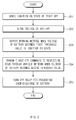
- FIG. 2 is a flowchart illustrating a method of preventing over-discharge of a battery for a vehicle according to an exemplary embodiment of the present disclosure.
- the power state sensor 150 may sense an ignition-on state (201).
- the voltage sensor 110 may sense the voltage of the battery 100 (202).
- the controller 170 may output the warning message (203).
- the controller 170 may transmit the shut-off commands to the respective ECUs through the vehicle network (204).
- the controller 170 may turn off the relay 120 for preventing the over-discharge of the battery 100 (205).
- the controller may control the shut-off sequences of the respective controller in the vehicle to be performed, thereby making it possible to safely protect the respective controller in the vehicle as well as the lithium ion battery of 12V.
- the method of preventing over-discharge of a battery for a vehicle according to an exemplary embodiment of the present disclosure as described above may be created, or implemented, by a computer program.
- codes and code segments configuring the computer program may be easily inferred, and/or produced, by a computer programmer skilled in the related art.
- the created computer program is stored in a computer-readable recording medium (information storing medium) and is read and executed by a computer to implement the method of preventing over-discharge of a battery for a vehicle according to an exemplary embodiment of the present disclosure.
- the computer-readable recording medium includes all types of recording media that are readable by the computer.
- the respective controllers in the vehicle as well as the battery (for example, the lithium ion battery of 12V) supplying power to the electric loads of the vehicle by controlling the shut-off sequences of the respective controllers in the vehicle to be performed at the time of turning off the relay for preventing the over-discharge of the lithium ion battery of 12V.
- the battery for example, the lithium ion battery of 12V
- the present disclosure may be applied to an eco-friendly vehicle.
- the eco-friendly vehicle which is a vehicle driven by driving an electrical motor using a high voltage battery, includes a hybrid electric vehicle (HEV), an electric vehicle (EV), a plug-in hybrid electric vehicle (PHEV), a fuel cell electric vehicle (FCEV), and the like.
- HEV hybrid electric vehicle
- EV electric vehicle
- PHEV plug-in hybrid electric vehicle
- FCEV fuel cell electric vehicle
Landscapes
- Engineering & Computer Science (AREA)
- Power Engineering (AREA)
- Mechanical Engineering (AREA)
- Transportation (AREA)
- Sustainable Development (AREA)
- Sustainable Energy (AREA)
- Life Sciences & Earth Sciences (AREA)
- Charge And Discharge Circuits For Batteries Or The Like (AREA)
- Secondary Cells (AREA)
- Electric Propulsion And Braking For Vehicles (AREA)
- Manufacturing & Machinery (AREA)
- Chemical & Material Sciences (AREA)
- Chemical Kinetics & Catalysis (AREA)
- Electrochemistry (AREA)
- General Chemical & Material Sciences (AREA)
Abstract
Description
- This application claims the benefit of priority to Korean Patent Application No.
10-2015-0164324, filed on November 23, 2015 - The present disclosure relates to an apparatus and a method of preventing over-discharge of a vehicle battery, and more particularly, to a technology of protecting controllers as well as a battery (for example, a lithium ion battery of 12V) supplying power to electric loads of a vehicle by controlling shut-off sequences of the controllers in the vehicle to be performed at the time of turning off a relay for preventing over-discharge of a lithium ion battery.
- Generally, a vehicle includes a high voltage battery for supplying driving power and an auxiliary battery for supplying operation power to an internal electrical apparatus (an electric load). Here, a low voltage direct current (DC) to DC converter (LDC) connected to the auxiliary battery and the electrical apparatus down-converts a high voltage of the high voltage battery into a voltage for charging the auxiliary battery when a voltage of the auxiliary battery does not exceed a reference value under a control of a higher controller.
- The auxiliary battery serves to supply operation power to electrical apparatus such as lamps, systems, electronic control units (ECUs), and the like, as well as for starting the vehicle.
- Lead-acid storage batteries have been mainly used as the auxiliary battery of a vehicle since lead-acid may be recharged and be used even though they are completely discharged. However, a lead-acid storage battery is heavy and has a low charging density, and lead-acid used in the lead-acid storage battery may have adverse environmental effects. Therefore, the lead-acid storage battery has been replaced by a lithium ion battery in an some vehicles.
- However, when a lithium ion battery is over-discharged, performance deterioration of the lithium ion battery may appear at the time of recharging the lithium ion battery. Therefore, in order to address this situation, technologies of preventing over-discharge of the lithium ion battery by allowing a battery management system (BMS) to include a relay for preventing the over-discharge have been developed.
- There exists a conventional technology of protecting a battery for a vehicle by turning off a relay when the battery for a vehicle is in an over-discharge state. However, this technology may be a technology of simply protecting only the battery for a vehicle, and may not protect the respective controllers in the vehicle that are being operated in an ignition-on state.
- The present disclosure has been made to solve the above-mentioned problems occurring in the prior art while advantages achieved by the prior art are maintained intact.
- An aspect of the present disclosure provides an apparatus and a method of preventing over-discharge of a battery for a vehicle capable of safely protecting the respective controllers in the vehicle as well as a battery (for example, a lithium ion battery of 12V) supplying power to electric loads of the vehicle by controlling shut-off sequences of the respective controllers in the vehicle to be performed at the time of turning off a relay for preventing over-discharge of the lithium ion battery of 12V.
- Objects of the present disclosure are not limited to the above-mentioned object, and other objects and advantages of the present disclosure that are not mentioned may be understood by the following description and will be more clearly appreciated by exemplary embodiments of the present disclosure. In addition, it may be easily appreciated that objects and advantages of the present disclosure may be realized by means mentioned in the claims and a combination thereof.
- According to an exemplary embodiment of the present disclosure, an apparatus of preventing over-discharge of a battery for a vehicle may include: a voltage sensor for sensing a voltage of the battery; a relay for preventing the over-discharge of the battery; a power state sensor for sensing an ignition on state; and a controller for outputting a warning message when the voltage of the battery becomes a first threshold value in the ignition on state and turning off the relay after transmitting shut-off commands to the respective electronic control units (ECUs) through a vehicle network when the voltage of the battery becomes a second threshold value.
- According to another exemplary embodiment of the present disclosure, a method of preventing over-discharge of a battery for a vehicle may include: sensing an ignition on state by a power state sensor; sensing a voltage of the battery by a voltage sensor; outputting a warning message by a controller when the voltage of the battery becomes a first threshold value in the ignition on state; transmitting shut-off commands to the respective ECUs through a vehicle network by the controller when the voltage of the battery becomes a second threshold value; and turning off a relay for preventing the over-discharge of the battery by the controller.
- The above and other objects, features and advantages of the present disclosure will be more apparent from the following detailed description taken in conjunction with the accompanying drawings.
-
FIG. 1 is a block diagram illustrating an apparatus for preventing over-discharge of a vehicle battery according to an exemplary embodiment of the present disclosure. -
FIG. 2 is a flowchart illustrating a method of preventing over-discharge of a vehicle battery according to an exemplary embodiment of the present disclosure. - The above-mentioned objects, features, and advantages will become more obvious from the following description described below in detail with reference to the accompanying drawings. Therefore, those skilled in the art to which the present disclosure pertains may easily practice a technical idea, or concept, of the present disclosure. Further, in describing the present disclosure, in the case in which it is decided that a detailed description of a well-known technology associated with the present disclosure may unnecessarily obscure concepts of the present disclosure, such description will be omitted. Hereinafter, exemplary embodiments of the present disclosure will be described in detail with reference to the accompanying drawings.
-
FIG. 1 is a block diagram illustrating an apparatus of preventing over-discharge of a vehicle battery according to an exemplary embodiment of the present disclosure. - As illustrated in
FIG. 1 , an apparatus of preventing over-discharge of a battery for a vehicle according to an exemplary embodiment of the present disclosure may include abattery 100, avoltage sensor 110, arelay 120, acurrent sensor 130, an engine room junction box (J/B) 140, apower state sensor 150, aswitch 160, acontroller 170, and the like. - The respective components will now be described. The
battery 100, which may be a lithium ion battery of 12V (a low-voltage auxiliary battery), supplies power required for electric loads of the vehicle. Thebattery 100 may also be implemented by a lead-acid storage battery, or another type of battery. - Next, the
voltage sensor 110 may sense a voltage of thebattery 100. - Next, the
relay 120 may serve to supply power from thebattery 100 to the electric loads or to block the supply of the power from thebattery 100 to the electric loads, thereby making it possible to prevent over-discharge of thebattery 100 and completely block thebattery 100 from a dark current flowing to the electric loads. Here, therelay 120 may be implemented by a latching type relay controlled by a pulse signal. - Next, the
current sensor 130 may be positioned between therelay 120 and the engineroom junction box 140, and sense a current of thebattery 100. - Next, the engine
room junction box 140 may include lines for branching power of thebattery 100 into the respective electric loads. The engineroom junction box 140 may supply operation power to thepower state sensor 150. - Next, the
power state sensor 150 may sense a state (hereinafter, referred to as a power state) in which the power of thebattery 100 is supplied to the electric loads. Here, the power state may include four states including a lock state, an accessory (ACC) state, an ignition on (ON) state, and a start state, which may be applied to, and used with, a start key scheme and a start button scheme. In the present disclosure, the ignition on state may mean a state in which the power of thebattery 100 is to be supplied to electric loads of a vehicle. - Next, the
switch 160, which may be a passive switch, may be operated by a manipulation of a user to turn on therelay 120. That is, in a state in which thecontroller 170 turns off therelay 120 in order to prevent the over-discharge of thebattery 100, when a driver gets into the vehicle and turns on theswitch 160, therelay 120 may be turned on, such that the power from thebattery 100 is supplied to the electric loads. - Next, the
controller 170 may perform a general control so that the respective components described above may normally perform their functions. - Particularly, the
controller 170 may turn off therelay 120 using aswitch 171 provided therein in order to prevent the over-discharge of thebattery 100 supplying the power to the electric loads of the vehicle. - That is, as a relay turn-off preparing step, the
controller 170 may output a warning message for inducing the start of the vehicle by the driver through a cluster, or another indication method, when a voltage of thebattery 100 in the ignition on state becomes a first threshold value (for example, 11V). - Then, in a relay turn-off step, the
controller 170 may turn off therelay 120 after transmitting shut-off commands to electronic control units (ECUs) in the vehicle through a vehicle network, when the vehicle is not started by the driver, such that the voltage of thebattery 100 becomes a second threshold value (smaller than the first threshold value (for example, 10.5V)). Here, thecontroller 170 may turn off therelay 120 after receiving completion messages from the respective ECUs in the vehicle, monitor outputs of the ECUs through the vehicle network and turn off therelay 120 in the case in which the ECUs are not operated, or turn off therelay 120 after thecontroller 170 transmits shut-off commands to the respective ECUs in the vehicle and a predetermined time elapses. - Here, the vehicle network may include a controller area network (CAN), a local interconnection network (LIN), a FlexRay, a media oriented system transport (MOST), and the like.
- Then, the
controller 170 may output a warning message through the cluster when the driver turns on the relay using theswitch 160 and then may perform ignition-on, and may perform a post-processing process of again turning off therelay 120 when the vehicle does not start in a threshold time. - The post-processing process may be repeatedly performed by the set number of times. The threshold time may be set to be short, or shortened, as the number of times of the repeatedly performed post-processing process is increased. For example, in the case in which the number of times the repeatedly performed post-processing process is performed is three, the threshold time may be set to 3 minutes in a primary number of times, may be set to 1 minute in a secondary number of times, and may be set to 30 seconds in a tertiary number of times.
- In addition, when the number of times of the repeatedly performed post-processing process is performed exceeds the set number of times, the use of the
battery 100 may be completely blocked. Then, only in the case in which an after-sale service - (AS) mechanic directly accesses a system to release the blocking, the
battery 100 may be used. - The present disclosure may be implemented so as not to be operated for the purpose of safety of the driver in the case in which the vehicle is being driven. However, in the case in which the over-discharge of the
battery 100 is sensed, the vehicle may enter a limp home mode (an emergency control mode or a safety mode). - In addition, in the present disclosure, the respective ECUs in the vehicle may perform shut-off sequences for stably shutting off the system depending on the shut-off commands.
-
FIG. 2 is a flowchart illustrating a method of preventing over-discharge of a battery for a vehicle according to an exemplary embodiment of the present disclosure. - First, the
power state sensor 150 may sense an ignition-on state (201). - Then, the
voltage sensor 110 may sense the voltage of the battery 100 (202). - Then, when the voltage of the
battery 100 becomes the first threshold value (for example, 11V) in the ignition on state, thecontroller 170 may output the warning message (203). - When the voltage of the
battery 100 becomes the second threshold value (for example, 10.5V) with the passage of time, thecontroller 170 may transmit the shut-off commands to the respective ECUs through the vehicle network (204). - Then, the
controller 170 may turn off therelay 120 for preventing the over-discharge of the battery 100 (205). - Through the process described above, the controller may control the shut-off sequences of the respective controller in the vehicle to be performed, thereby making it possible to safely protect the respective controller in the vehicle as well as the lithium ion battery of 12V.
- Meanwhile, the method of preventing over-discharge of a battery for a vehicle according to an exemplary embodiment of the present disclosure as described above may be created, or implemented, by a computer program. In addition, codes and code segments configuring the computer program may be easily inferred, and/or produced, by a computer programmer skilled in the related art. Further, the created computer program is stored in a computer-readable recording medium (information storing medium) and is read and executed by a computer to implement the method of preventing over-discharge of a battery for a vehicle according to an exemplary embodiment of the present disclosure. Further, the computer-readable recording medium includes all types of recording media that are readable by the computer.
- As described above, according to exemplary embodiments of the present disclosure, it is possible to safely protect the respective controllers in the vehicle as well as the battery (for example, the lithium ion battery of 12V) supplying power to the electric loads of the vehicle by controlling the shut-off sequences of the respective controllers in the vehicle to be performed at the time of turning off the relay for preventing the over-discharge of the lithium ion battery of 12V.
- In addition, according to exemplary embodiments of the present disclosure, it is possible to promote safety of passengers in the vehicle as well as the vehicle by prohibiting the turn-off of the relay in a state in which the vehicle starts or is being driven.
- The present disclosure may be applied to an eco-friendly vehicle. The eco-friendly vehicle, which is a vehicle driven by driving an electrical motor using a high voltage battery, includes a hybrid electric vehicle (HEV), an electric vehicle (EV), a plug-in hybrid electric vehicle (PHEV), a fuel cell electric vehicle (FCEV), and the like.
- Hereinabove, although the present disclosure has been described with reference to exemplary embodiments and the accompanying drawings, the present disclosure is not limited thereto, but may be variously modified and altered by those skilled in the art to which the present disclosure pertains without departing from the spirit and scope of the present disclosure claimed in the following claims.
-
- 100: BATTERY
- 150: POWER STATE SENSOR
- 201: SENSE IGNITION ON STATE OF START-OFF
- 202: SENSE VOLTAGE OF BATTERY
- S203: OUTPUT WARNING MESSAGE WHEN VOLTAGE OF BATTERY BECOMES
- FIRST THRESHOLD VALUE IN IGNITION ON STATE
- 204: TRANSMIT SHUT-OFF COMMANDS TO RESPECTIVE ECUS THROUGH
- VEHICLE NETWORK WHEN VOLTAGE OF BATTERY BECOMES SECOND
- THRESHOLD VALUE
- 205: TURN OFF RELAY FOR PREVENTING OVER-DISCHARGE OF BATTERY
Claims (15)
- An apparatus of preventing over-discharge of a battery for a vehicle, comprising:a voltage sensor for sensing a voltage of the battery;a relay for preventing the over-discharge of the battery;a power state sensor for sensing an ignition on state; anda controller for outputting a warning message when the voltage of the battery becomes a first threshold value in the ignition on state and for turning off the relay after transmitting shut-off commands to the respective electronic control units (ECUs) through a vehicle network when the voltage of the battery becomes a second threshold value.
- The apparatus of preventing over-discharge of a battery for a vehicle according to claim 1, wherein the controller turns off the relay after receiving completion messages from the respective ECUs in the vehicle.
- The apparatus of preventing over-discharge of a battery for a vehicle according to claim 1, wherein the controller monitors operations of the respective ECUs through the vehicle network and turns off the relay in the case in which the respective ECUs are not operated.
- The apparatus of preventing over-discharge of a battery for a vehicle according to claim 1, wherein the controller turns off the relay after the controller transmits the shut-off commands to the respective ECUs in the vehicle and a first threshold time elapses.
- The apparatus of preventing over-discharge of a battery for a vehicle according to any one of claims 1 to 4, further comprising a passive switch for turning on the relay,
wherein the controller again outputs the warning message through a cluster when the relay is turned on by the passive switch and the ignition on state is entered, and performs a post-processing process of again turning off the relay when the vehicle does not start in a second threshold time. - The apparatus of preventing over-discharge of a battery for a vehicle according to claim 5, wherein the controller repeatedly performs the post-processing process by the set number of times, and blocks the use of the battery when the number of times of the repeatedly performed post-processing process exceeds the set number of times.
- The apparatus of preventing over-discharge of a battery for a vehicle according to claim 5 or 6, wherein the controller sets the second threshold time to be shorter as the number of times of the repeatedly performed post-processing process is increased.
- The apparatus of preventing over-discharge of a battery for a vehicle according to any one of claims 1 to 7, wherein the relay is a latching type relay controlled by a pulse signal.
- A method of preventing over-discharge of a battery for a vehicle, comprising:sensing an ignition on state by a power state sensor;sensing a voltage of the battery by a voltage sensor;outputting a warning message by a controller when the voltage of the battery becomes a first threshold value in the ignition on state;transmitting shut-off commands to the respective ECUs through a vehicle network by the controller when the voltage of the battery becomes a second threshold value; andturning off a relay for preventing the over-discharge of the battery by the controller.
- The method of preventing over-discharge of a battery for a vehicle according to claim 9, wherein in the step of turning off the relay, the relay is turned off after completion messages are received from the respective ECUs in the vehicle.
- The method of preventing over-discharge of a battery for a vehicle according to claim 9, wherein in the step of turning off the relay, operations of the respective ECUs are monitored through the vehicle network, and the relay is turned off in the case in which the respective ECUs are not operated.
- The method of preventing over-discharge of a battery for a vehicle according to claim 9, wherein in the step of turning off the relay, the relay is turned off after the shut-off commands are transmitted to the respective ECUs in the vehicle and a first threshold time elapses.
- The method of preventing over-discharge of a battery for a vehicle according to any one of claims 9 to 12, further comprising:turning on the relay by a passive switch; andagain outputting the warning message through a cluster by the controller when the ignition on state is again entered by a driver and performing a post-processing process of again turning off the relay when the vehicle does not start in a second threshold time.
- The method of preventing over-discharge of a battery for a vehicle according to claim 13, wherein the post-processing process is repeatedly performed by the set number of times, and the use of the battery is blocked by the controller when the number of times of the repeatedly performed post-processing process exceeds the set number of times.
- The method of preventing over-discharge of a battery for a vehicle according to claim 13 or 14, wherein the second threshold time is set to be shorter as the number of times of the repeatedly performed post-processing process is increased.
Applications Claiming Priority (1)
| Application Number | Priority Date | Filing Date | Title |
|---|---|---|---|
| KR1020150164324A KR101755894B1 (en) | 2015-11-23 | 2015-11-23 | Apparatus for preventing over discharge of vehicle battery and method thereof |
Publications (3)
| Publication Number | Publication Date |
|---|---|
| EP3170691A2 true EP3170691A2 (en) | 2017-05-24 |
| EP3170691A3 EP3170691A3 (en) | 2017-06-07 |
| EP3170691B1 EP3170691B1 (en) | 2020-04-15 |
Family
ID=56344983
Family Applications (1)
| Application Number | Title | Priority Date | Filing Date |
|---|---|---|---|
| EP16175405.6A Active EP3170691B1 (en) | 2015-11-23 | 2016-06-21 | Apparatus and method of preventing over-discharge of vehicle battery |
Country Status (5)
| Country | Link |
|---|---|
| US (1) | US9884557B2 (en) |
| EP (1) | EP3170691B1 (en) |
| JP (1) | JP6710581B2 (en) |
| KR (1) | KR101755894B1 (en) |
| CN (1) | CN106740567B (en) |
Cited By (1)
| Publication number | Priority date | Publication date | Assignee | Title |
|---|---|---|---|---|
| CN110182097A (en) * | 2018-02-22 | 2019-08-30 | 丰田自动车株式会社 | Vehicular power supply system |
Families Citing this family (28)
| Publication number | Priority date | Publication date | Assignee | Title |
|---|---|---|---|---|
| KR20170052095A (en) * | 2015-11-03 | 2017-05-12 | 현대자동차주식회사 | Battery control system and method for detecting fusion of relay |
| KR101866063B1 (en) * | 2016-10-07 | 2018-06-08 | 현대자동차주식회사 | System for controlling relay of an auxiliary battery and method thereof |
| US11043723B2 (en) * | 2016-11-24 | 2021-06-22 | R & WJ Enterprises Pty Ltd | Low voltage protector for systems battery |
| US10757113B2 (en) * | 2017-03-17 | 2020-08-25 | Cylance Inc. | Communications bus signal fingerprinting |
| US10275615B2 (en) | 2017-03-17 | 2019-04-30 | Cylance Inc. | Communications bus data transmission using relative ground shifting |
| US10462155B2 (en) | 2017-03-17 | 2019-10-29 | Cylance Inc. | Electronic control unit protection framework using security zones |
| KR101967464B1 (en) | 2018-04-12 | 2019-04-09 | 현대오트론 주식회사 | Method for preventing battery discharge and electronic control unit using the same |
| US10608447B2 (en) | 2018-06-11 | 2020-03-31 | Ford Global Technologies, Llc | System and method for avoiding depleted battery in a parked vehicle |
| CN108839624B (en) * | 2018-06-28 | 2020-10-30 | 潍柴动力股份有限公司 | Automobile ignition switch control system and method |
| CN110877585A (en) * | 2018-09-06 | 2020-03-13 | 北汽福田汽车股份有限公司 | Power management device and method |
| CN109450429B (en) * | 2018-10-26 | 2022-07-08 | 南京汽车集团有限公司 | Vehicle power supply control switch and control method |
| KR102440317B1 (en) | 2018-11-08 | 2022-09-02 | 주식회사 엘지에너지솔루션 | Relay Switch device for turning on / off the large current of the battery pack |
| US11251626B2 (en) * | 2019-01-15 | 2022-02-15 | Lithium Power Inc. | System for lead-acid battery replacement |
| JP2020150629A (en) * | 2019-03-12 | 2020-09-17 | 株式会社竹内製作所 | DC power supply circuit for work vehicles |
| DE102019129170A1 (en) * | 2019-10-29 | 2021-04-29 | Volkswagen Aktiengesellschaft | Control arrangement for a high-voltage battery and method for operating a control arrangement |
| CN112776670B (en) * | 2019-11-08 | 2023-02-03 | 长城汽车股份有限公司 | A battery control method, system and vehicle |
| JP7226356B2 (en) * | 2020-02-03 | 2023-02-21 | トヨタ自動車株式会社 | VEHICLE CONTROL DEVICE, METHOD, PROGRAM, AND VEHICLE |
| US11262408B2 (en) | 2020-02-24 | 2022-03-01 | Ford Global Technologies, Llc | Vehicle traction battery over-discharge diagnosing method and assembly |
| CN111717051B (en) * | 2020-06-30 | 2022-05-03 | 重庆长安新能源汽车科技有限公司 | Protection control method for electronic lock of pure electric vehicle |
| KR102849475B1 (en) * | 2020-08-31 | 2025-08-22 | 주식회사 엘지에너지솔루션 | Battery protection circuit and its protection method |
| JP7380535B2 (en) * | 2020-11-19 | 2023-11-15 | トヨタ自動車株式会社 | Battery monitoring device, method, program, and vehicle |
| CN112693361B (en) * | 2020-12-28 | 2022-10-28 | 潍柴动力股份有限公司 | Battery protection system and method |
| US11787357B2 (en) | 2021-01-27 | 2023-10-17 | Ford Global Technologies, Llc | Enhanced power management |
| KR102571348B1 (en) * | 2021-03-15 | 2023-08-30 | 현대자동차주식회사 | Vehicle and method for controlling thereof |
| CN114013280A (en) * | 2021-10-28 | 2022-02-08 | 浙江吉利控股集团有限公司 | Vehicle double-motor control architecture, and discharge function safety control method and system |
| CN115954992B (en) * | 2023-03-14 | 2023-05-23 | 银河航天(西安)科技有限公司 | Storage battery over-discharge protection method based on Markov chain |
| US12613266B2 (en) | 2023-09-07 | 2026-04-28 | Ford Global Technologies, Llc | Vehicle key-off load monitoring |
| US20260034948A1 (en) * | 2024-08-05 | 2026-02-05 | Ford Global Technologies, Llc | Systems and methods for mitigating vehicle battery drain |
Family Cites Families (26)
| Publication number | Priority date | Publication date | Assignee | Title |
|---|---|---|---|---|
| JPH06209529A (en) * | 1992-12-29 | 1994-07-26 | Canon Inc | Power control device |
| JPH09215213A (en) * | 1996-02-05 | 1997-08-15 | Fuji Elelctrochem Co Ltd | Over-discharge prevention device |
| KR19990005310U (en) | 1997-07-15 | 1999-02-18 | 홍종만 | Battery discharge protector |
| JPH1169637A (en) * | 1997-08-15 | 1999-03-09 | Kokusai Electric Co Ltd | Portable electronic devices |
| US7421323B2 (en) * | 2005-05-03 | 2008-09-02 | International Truck Intellectual Property Company, Llc | Automated vehicle battery protection with programmable load shedding and engine speed control |
| JP2007210473A (en) * | 2006-02-09 | 2007-08-23 | Fuji Heavy Ind Ltd | In-vehicle battery voltage monitoring device |
| JP2007236033A (en) * | 2006-02-27 | 2007-09-13 | Sony Corp | Battery pack and battery protection method |
| JP2007237768A (en) * | 2006-03-06 | 2007-09-20 | Fujitsu Ten Ltd | Power management device and power management system |
| US7847519B2 (en) * | 2008-05-09 | 2010-12-07 | Neotec Semiconductor Ltd. | Smart battery protector with impedance compensation |
| JP5326517B2 (en) * | 2008-11-21 | 2013-10-30 | ソニー株式会社 | Integrated circuit and battery pack using the same |
| WO2010109956A1 (en) * | 2009-03-27 | 2010-09-30 | 株式会社日立製作所 | Electric storage device |
| JP2011165420A (en) * | 2010-02-08 | 2011-08-25 | Hitachi Koki Co Ltd | Battery pack, and power tool |
| KR20110134018A (en) | 2010-06-08 | 2011-12-14 | 현대자동차주식회사 | How to protect your battery in a hybrid vehicle |
| JP2012092586A (en) | 2010-10-27 | 2012-05-17 | Sumitomo (Shi) Construction Machinery Co Ltd | Battery discharge-prevention circuit for construction machine |
| KR101251525B1 (en) | 2011-07-27 | 2013-04-05 | 현대자동차주식회사 | Control method for electric vehicle |
| KR20130068160A (en) * | 2011-12-14 | 2013-06-26 | 한국전자통신연구원 | Structure for energy management system and energy managemant method in electric vehicel |
| US9114709B2 (en) * | 2012-02-24 | 2015-08-25 | Ford Global Technologies, Llc | Limited operating strategy for an electric vehicle |
| CN102815221B (en) * | 2012-06-07 | 2015-01-14 | 广州益维电动汽车有限公司 | Electromobile power platform system with integrative control |
| DE102012211393A1 (en) | 2012-07-02 | 2014-01-02 | Robert Bosch Gmbh | Battery and motor vehicle |
| BR112015000006B1 (en) * | 2012-07-04 | 2021-06-08 | Volvo Truck Corporation | method for controlling a hybrid vehicle-vehicle electrical system using such a method |
| KR101428262B1 (en) * | 2012-12-10 | 2014-08-07 | 현대자동차주식회사 | Power control system for vehicle battery |
| JP6157861B2 (en) * | 2013-01-22 | 2017-07-05 | 株式会社東芝 | Power control device |
| US9393920B2 (en) * | 2013-05-20 | 2016-07-19 | General Motors Llc | Telematics-based system for protecting against vehicle battery drain |
| JP6530586B2 (en) * | 2013-12-06 | 2019-06-12 | ミツミ電機株式会社 | Secondary protection IC, control method for secondary protection IC, protection module, and battery pack |
| JP6156190B2 (en) * | 2014-02-27 | 2017-07-05 | ソニー株式会社 | Negative electrode active material, battery, battery pack, electronic device, electric vehicle, power storage device, and power system |
| CN104578324A (en) * | 2015-02-04 | 2015-04-29 | 环旭电子股份有限公司 | Battery drive device |
-
2015
- 2015-11-23 KR KR1020150164324A patent/KR101755894B1/en active Active
-
2016
- 2016-05-31 JP JP2016109254A patent/JP6710581B2/en active Active
- 2016-06-21 EP EP16175405.6A patent/EP3170691B1/en active Active
- 2016-07-01 US US15/200,678 patent/US9884557B2/en active Active
- 2016-07-13 CN CN201610552129.2A patent/CN106740567B/en active Active
Non-Patent Citations (1)
| Title |
|---|
| None |
Cited By (2)
| Publication number | Priority date | Publication date | Assignee | Title |
|---|---|---|---|---|
| CN110182097A (en) * | 2018-02-22 | 2019-08-30 | 丰田自动车株式会社 | Vehicular power supply system |
| CN110182097B (en) * | 2018-02-22 | 2022-08-30 | 丰田自动车株式会社 | Vehicle power supply system |
Also Published As
| Publication number | Publication date |
|---|---|
| KR20170059844A (en) | 2017-05-31 |
| KR101755894B1 (en) | 2017-07-19 |
| JP2017099250A (en) | 2017-06-01 |
| CN106740567B (en) | 2021-05-04 |
| EP3170691A3 (en) | 2017-06-07 |
| US20170144549A1 (en) | 2017-05-25 |
| EP3170691B1 (en) | 2020-04-15 |
| US9884557B2 (en) | 2018-02-06 |
| CN106740567A (en) | 2017-05-31 |
| JP6710581B2 (en) | 2020-06-17 |
Similar Documents
| Publication | Publication Date | Title |
|---|---|---|
| US9884557B2 (en) | Apparatus and method of preventing over-discharge of vehicle battery | |
| CN108068652B (en) | Battery recharge notification and automatic recharge | |
| KR101910918B1 (en) | Vehicle and method of recharging battery therein | |
| EP2957016B1 (en) | Hybrid vehicle running control apparatus | |
| KR101673822B1 (en) | Apparatus and method for detecting relay welding in green car | |
| EP2950419A1 (en) | Electric power supply control device and electric power supply control method | |
| US20140232302A1 (en) | Battery processing apparatus, vehicle, battery processing method, and battery processing program | |
| US9346366B2 (en) | Charge/discharge system | |
| US10220721B2 (en) | System and method for controlling a relay of an auxiliary battery | |
| US20170197521A1 (en) | Method and apparatus for preventing deep discharging of auxiliary battery in association with reprogramming of ecu | |
| US9662988B2 (en) | System and method for power management of off-board loads being powered and/or charged by an electric vehicle | |
| EP3118965A1 (en) | Apparatus for controlling supply of power of battery | |
| US20120286568A1 (en) | Methods and Circuits for Controlling a Battery Disconnect Switch | |
| JP2015091157A (en) | Charging control device, vehicle, vehicle charging system, charging control method, and program | |
| JP6622135B2 (en) | Power supply | |
| CN106300470A (en) | Start battery and start the control method of battery and include the automobile of this startup battery | |
| JP2017119454A (en) | Power supply management device and abnormality detection method | |
| JP2012205469A (en) | Power supply device, power control device, and power supply program | |
| EP4606625A1 (en) | Power supply device, power supply system, and vehicle | |
| CN117341475A (en) | A charging control method, device, equipment and medium for electric vehicle batteries | |
| JP2021151070A (en) | Device and method for battery control | |
| CN111762033A (en) | Method and device for controlling vehicle power supply, storage medium and vehicle | |
| KR20160049900A (en) | Safety system for high voltage battery of green car and operating method thereof |
Legal Events
| Date | Code | Title | Description |
|---|---|---|---|
| PUAI | Public reference made under article 153(3) epc to a published international application that has entered the european phase |
Free format text: ORIGINAL CODE: 0009012 |
|
| STAA | Information on the status of an ep patent application or granted ep patent |
Free format text: STATUS: THE APPLICATION HAS BEEN PUBLISHED |
|
| AK | Designated contracting states |
Kind code of ref document: A2 Designated state(s): AL AT BE BG CH CY CZ DE DK EE ES FI FR GB GR HR HU IE IS IT LI LT LU LV MC MK MT NL NO PL PT RO RS SE SI SK SM TR |
|
| AX | Request for extension of the european patent |
Extension state: BA ME |
|
| AK | Designated contracting states |
Kind code of ref document: A3 Designated state(s): AL AT BE BG CH CY CZ DE DK EE ES FI FR GB GR HR HU IE IS IT LI LT LU LV MC MK MT NL NO PL PT RO RS SE SI SK SM TR |
|
| AX | Request for extension of the european patent |
Extension state: BA ME |
|
| RIC1 | Information provided on ipc code assigned before grant |
Ipc: H02J 7/00 20060101ALI20170502BHEP Ipc: B60L 11/18 20060101AFI20170502BHEP Ipc: B60L 1/00 20060101ALI20170502BHEP Ipc: B60W 10/26 20060101ALI20170502BHEP Ipc: B60L 3/04 20060101ALI20170502BHEP |
|
| PUAL | Search report despatched |
Free format text: ORIGINAL CODE: 0009013 |
|
| STAA | Information on the status of an ep patent application or granted ep patent |
Free format text: STATUS: REQUEST FOR EXAMINATION WAS MADE |
|
| 17P | Request for examination filed |
Effective date: 20171207 |
|
| RBV | Designated contracting states (corrected) |
Designated state(s): AL AT BE BG CH CY CZ DE DK EE ES FI FR GB GR HR HU IE IS IT LI LT LU LV MC MK MT NL NO PL PT RO RS SE SI SK SM TR |
|
| STAA | Information on the status of an ep patent application or granted ep patent |
Free format text: STATUS: EXAMINATION IS IN PROGRESS |
|
| 17Q | First examination report despatched |
Effective date: 20180419 |
|
| REG | Reference to a national code |
Ref country code: DE Ref legal event code: R079 Ref document number: 602016033922 Country of ref document: DE Free format text: PREVIOUS MAIN CLASS: B60L0011180000 Ipc: B60L0058100000 |
|
| RIC1 | Information provided on ipc code assigned before grant |
Ipc: B60L 3/04 20060101ALI20191010BHEP Ipc: H02J 7/00 20060101ALI20191010BHEP Ipc: B60L 58/10 20190101AFI20191010BHEP Ipc: B60L 58/12 20190101ALI20191010BHEP Ipc: B60L 58/14 20190101ALI20191010BHEP Ipc: B60L 1/00 20060101ALI20191010BHEP |
|
| GRAP | Despatch of communication of intention to grant a patent |
Free format text: ORIGINAL CODE: EPIDOSNIGR1 |
|
| STAA | Information on the status of an ep patent application or granted ep patent |
Free format text: STATUS: GRANT OF PATENT IS INTENDED |
|
| INTG | Intention to grant announced |
Effective date: 20200103 |
|
| GRAS | Grant fee paid |
Free format text: ORIGINAL CODE: EPIDOSNIGR3 |
|
| GRAA | (expected) grant |
Free format text: ORIGINAL CODE: 0009210 |
|
| STAA | Information on the status of an ep patent application or granted ep patent |
Free format text: STATUS: THE PATENT HAS BEEN GRANTED |
|
| AK | Designated contracting states |
Kind code of ref document: B1 Designated state(s): AL AT BE BG CH CY CZ DE DK EE ES FI FR GB GR HR HU IE IS IT LI LT LU LV MC MK MT NL NO PL PT RO RS SE SI SK SM TR |
|
| REG | Reference to a national code |
Ref country code: CH Ref legal event code: EP |
|
| REG | Reference to a national code |
Ref country code: DE Ref legal event code: R096 Ref document number: 602016033922 Country of ref document: DE |
|
| REG | Reference to a national code |
Ref country code: IE Ref legal event code: FG4D |
|
| REG | Reference to a national code |
Ref country code: AT Ref legal event code: REF Ref document number: 1256878 Country of ref document: AT Kind code of ref document: T Effective date: 20200515 |
|
| REG | Reference to a national code |
Ref country code: NO Ref legal event code: T2 Effective date: 20200415 |
|
| REG | Reference to a national code |
Ref country code: NL Ref legal event code: MP Effective date: 20200415 |
|
| REG | Reference to a national code |
Ref country code: LT Ref legal event code: MG4D |
|
| PG25 | Lapsed in a contracting state [announced via postgrant information from national office to epo] |
Ref country code: NL Free format text: LAPSE BECAUSE OF FAILURE TO SUBMIT A TRANSLATION OF THE DESCRIPTION OR TO PAY THE FEE WITHIN THE PRESCRIBED TIME-LIMIT Effective date: 20200415 Ref country code: SE Free format text: LAPSE BECAUSE OF FAILURE TO SUBMIT A TRANSLATION OF THE DESCRIPTION OR TO PAY THE FEE WITHIN THE PRESCRIBED TIME-LIMIT Effective date: 20200415 Ref country code: PT Free format text: LAPSE BECAUSE OF FAILURE TO SUBMIT A TRANSLATION OF THE DESCRIPTION OR TO PAY THE FEE WITHIN THE PRESCRIBED TIME-LIMIT Effective date: 20200817 Ref country code: LT Free format text: LAPSE BECAUSE OF FAILURE TO SUBMIT A TRANSLATION OF THE DESCRIPTION OR TO PAY THE FEE WITHIN THE PRESCRIBED TIME-LIMIT Effective date: 20200415 Ref country code: GR Free format text: LAPSE BECAUSE OF FAILURE TO SUBMIT A TRANSLATION OF THE DESCRIPTION OR TO PAY THE FEE WITHIN THE PRESCRIBED TIME-LIMIT Effective date: 20200716 Ref country code: IS Free format text: LAPSE BECAUSE OF FAILURE TO SUBMIT A TRANSLATION OF THE DESCRIPTION OR TO PAY THE FEE WITHIN THE PRESCRIBED TIME-LIMIT Effective date: 20200815 Ref country code: FI Free format text: LAPSE BECAUSE OF FAILURE TO SUBMIT A TRANSLATION OF THE DESCRIPTION OR TO PAY THE FEE WITHIN THE PRESCRIBED TIME-LIMIT Effective date: 20200415 |
|
| REG | Reference to a national code |
Ref country code: AT Ref legal event code: MK05 Ref document number: 1256878 Country of ref document: AT Kind code of ref document: T Effective date: 20200415 |
|
| PG25 | Lapsed in a contracting state [announced via postgrant information from national office to epo] |
Ref country code: LV Free format text: LAPSE BECAUSE OF FAILURE TO SUBMIT A TRANSLATION OF THE DESCRIPTION OR TO PAY THE FEE WITHIN THE PRESCRIBED TIME-LIMIT Effective date: 20200415 Ref country code: HR Free format text: LAPSE BECAUSE OF FAILURE TO SUBMIT A TRANSLATION OF THE DESCRIPTION OR TO PAY THE FEE WITHIN THE PRESCRIBED TIME-LIMIT Effective date: 20200415 Ref country code: RS Free format text: LAPSE BECAUSE OF FAILURE TO SUBMIT A TRANSLATION OF THE DESCRIPTION OR TO PAY THE FEE WITHIN THE PRESCRIBED TIME-LIMIT Effective date: 20200415 Ref country code: BG Free format text: LAPSE BECAUSE OF FAILURE TO SUBMIT A TRANSLATION OF THE DESCRIPTION OR TO PAY THE FEE WITHIN THE PRESCRIBED TIME-LIMIT Effective date: 20200715 |
|
| PG25 | Lapsed in a contracting state [announced via postgrant information from national office to epo] |
Ref country code: AL Free format text: LAPSE BECAUSE OF FAILURE TO SUBMIT A TRANSLATION OF THE DESCRIPTION OR TO PAY THE FEE WITHIN THE PRESCRIBED TIME-LIMIT Effective date: 20200415 |
|
| REG | Reference to a national code |
Ref country code: DE Ref legal event code: R097 Ref document number: 602016033922 Country of ref document: DE |
|
| PG25 | Lapsed in a contracting state [announced via postgrant information from national office to epo] |
Ref country code: CZ Free format text: LAPSE BECAUSE OF FAILURE TO SUBMIT A TRANSLATION OF THE DESCRIPTION OR TO PAY THE FEE WITHIN THE PRESCRIBED TIME-LIMIT Effective date: 20200415 Ref country code: RO Free format text: LAPSE BECAUSE OF FAILURE TO SUBMIT A TRANSLATION OF THE DESCRIPTION OR TO PAY THE FEE WITHIN THE PRESCRIBED TIME-LIMIT Effective date: 20200415 Ref country code: ES Free format text: LAPSE BECAUSE OF FAILURE TO SUBMIT A TRANSLATION OF THE DESCRIPTION OR TO PAY THE FEE WITHIN THE PRESCRIBED TIME-LIMIT Effective date: 20200415 Ref country code: MC Free format text: LAPSE BECAUSE OF FAILURE TO SUBMIT A TRANSLATION OF THE DESCRIPTION OR TO PAY THE FEE WITHIN THE PRESCRIBED TIME-LIMIT Effective date: 20200415 Ref country code: SM Free format text: LAPSE BECAUSE OF FAILURE TO SUBMIT A TRANSLATION OF THE DESCRIPTION OR TO PAY THE FEE WITHIN THE PRESCRIBED TIME-LIMIT Effective date: 20200415 Ref country code: EE Free format text: LAPSE BECAUSE OF FAILURE TO SUBMIT A TRANSLATION OF THE DESCRIPTION OR TO PAY THE FEE WITHIN THE PRESCRIBED TIME-LIMIT Effective date: 20200415 Ref country code: AT Free format text: LAPSE BECAUSE OF FAILURE TO SUBMIT A TRANSLATION OF THE DESCRIPTION OR TO PAY THE FEE WITHIN THE PRESCRIBED TIME-LIMIT Effective date: 20200415 Ref country code: DK Free format text: LAPSE BECAUSE OF FAILURE TO SUBMIT A TRANSLATION OF THE DESCRIPTION OR TO PAY THE FEE WITHIN THE PRESCRIBED TIME-LIMIT Effective date: 20200415 Ref country code: IT Free format text: LAPSE BECAUSE OF FAILURE TO SUBMIT A TRANSLATION OF THE DESCRIPTION OR TO PAY THE FEE WITHIN THE PRESCRIBED TIME-LIMIT Effective date: 20200415 |
|
| REG | Reference to a national code |
Ref country code: CH Ref legal event code: PL |
|
| PLBE | No opposition filed within time limit |
Free format text: ORIGINAL CODE: 0009261 |
|
| STAA | Information on the status of an ep patent application or granted ep patent |
Free format text: STATUS: NO OPPOSITION FILED WITHIN TIME LIMIT |
|
| PG25 | Lapsed in a contracting state [announced via postgrant information from national office to epo] |
Ref country code: SK Free format text: LAPSE BECAUSE OF FAILURE TO SUBMIT A TRANSLATION OF THE DESCRIPTION OR TO PAY THE FEE WITHIN THE PRESCRIBED TIME-LIMIT Effective date: 20200415 Ref country code: PL Free format text: LAPSE BECAUSE OF FAILURE TO SUBMIT A TRANSLATION OF THE DESCRIPTION OR TO PAY THE FEE WITHIN THE PRESCRIBED TIME-LIMIT Effective date: 20200415 |
|
| 26N | No opposition filed |
Effective date: 20210118 |
|
| PG25 | Lapsed in a contracting state [announced via postgrant information from national office to epo] |
Ref country code: LU Free format text: LAPSE BECAUSE OF NON-PAYMENT OF DUE FEES Effective date: 20200621 |
|
| REG | Reference to a national code |
Ref country code: BE Ref legal event code: MM Effective date: 20200630 |
|
| PG25 | Lapsed in a contracting state [announced via postgrant information from national office to epo] |
Ref country code: IE Free format text: LAPSE BECAUSE OF NON-PAYMENT OF DUE FEES Effective date: 20200621 Ref country code: CH Free format text: LAPSE BECAUSE OF NON-PAYMENT OF DUE FEES Effective date: 20200630 Ref country code: LI Free format text: LAPSE BECAUSE OF NON-PAYMENT OF DUE FEES Effective date: 20200630 |
|
| PG25 | Lapsed in a contracting state [announced via postgrant information from national office to epo] |
Ref country code: SI Free format text: LAPSE BECAUSE OF FAILURE TO SUBMIT A TRANSLATION OF THE DESCRIPTION OR TO PAY THE FEE WITHIN THE PRESCRIBED TIME-LIMIT Effective date: 20200415 Ref country code: BE Free format text: LAPSE BECAUSE OF NON-PAYMENT OF DUE FEES Effective date: 20200630 |
|
| PG25 | Lapsed in a contracting state [announced via postgrant information from national office to epo] |
Ref country code: TR Free format text: LAPSE BECAUSE OF FAILURE TO SUBMIT A TRANSLATION OF THE DESCRIPTION OR TO PAY THE FEE WITHIN THE PRESCRIBED TIME-LIMIT Effective date: 20200415 Ref country code: MT Free format text: LAPSE BECAUSE OF FAILURE TO SUBMIT A TRANSLATION OF THE DESCRIPTION OR TO PAY THE FEE WITHIN THE PRESCRIBED TIME-LIMIT Effective date: 20200415 Ref country code: CY Free format text: LAPSE BECAUSE OF FAILURE TO SUBMIT A TRANSLATION OF THE DESCRIPTION OR TO PAY THE FEE WITHIN THE PRESCRIBED TIME-LIMIT Effective date: 20200415 |
|
| PG25 | Lapsed in a contracting state [announced via postgrant information from national office to epo] |
Ref country code: MK Free format text: LAPSE BECAUSE OF FAILURE TO SUBMIT A TRANSLATION OF THE DESCRIPTION OR TO PAY THE FEE WITHIN THE PRESCRIBED TIME-LIMIT Effective date: 20200415 |
|
| P01 | Opt-out of the competence of the unified patent court (upc) registered |
Effective date: 20230523 |
|
| PGFP | Annual fee paid to national office [announced via postgrant information from national office to epo] |
Ref country code: DE Payment date: 20250520 Year of fee payment: 10 |
|
| PGFP | Annual fee paid to national office [announced via postgrant information from national office to epo] |
Ref country code: GB Payment date: 20250520 Year of fee payment: 10 |
|
| PGFP | Annual fee paid to national office [announced via postgrant information from national office to epo] |
Ref country code: NO Payment date: 20250523 Year of fee payment: 10 |
|
| PGFP | Annual fee paid to national office [announced via postgrant information from national office to epo] |
Ref country code: FR Payment date: 20250521 Year of fee payment: 10 |