EP3170665B1 - Method for operating a printing press having an anilox roller - Google Patents
Method for operating a printing press having an anilox roller Download PDFInfo
- Publication number
- EP3170665B1 EP3170665B1 EP16194540.7A EP16194540A EP3170665B1 EP 3170665 B1 EP3170665 B1 EP 3170665B1 EP 16194540 A EP16194540 A EP 16194540A EP 3170665 B1 EP3170665 B1 EP 3170665B1
- Authority
- EP
- European Patent Office
- Prior art keywords
- roller
- anilox roller
- anilox
- rider
- printing
- Prior art date
- Legal status (The legal status is an assumption and is not a legal conclusion. Google has not performed a legal analysis and makes no representation as to the accuracy of the status listed.)
- Active
Links
- 238000007774 anilox coating Methods 0.000 title claims description 127
- 238000007639 printing Methods 0.000 title claims description 58
- 238000000034 method Methods 0.000 title claims description 19
- 238000005096 rolling process Methods 0.000 claims description 12
- 239000012530 fluid Substances 0.000 claims description 6
- 238000011144 upstream manufacturing Methods 0.000 claims 1
- 238000011161 development Methods 0.000 description 9
- 230000018109 developmental process Effects 0.000 description 9
- 238000012546 transfer Methods 0.000 description 6
- 238000004040 coloring Methods 0.000 description 5
- 238000010586 diagram Methods 0.000 description 4
- 238000007645 offset printing Methods 0.000 description 4
- 230000002093 peripheral effect Effects 0.000 description 4
- 230000008859 change Effects 0.000 description 3
- 230000000694 effects Effects 0.000 description 3
- 238000005520 cutting process Methods 0.000 description 2
- 238000004519 manufacturing process Methods 0.000 description 2
- 230000019612 pigmentation Effects 0.000 description 2
- 238000012216 screening Methods 0.000 description 2
- 235000001543 Corylus americana Nutrition 0.000 description 1
- 240000007582 Corylus avellana Species 0.000 description 1
- 235000007466 Corylus avellana Nutrition 0.000 description 1
- 230000035508 accumulation Effects 0.000 description 1
- 238000009825 accumulation Methods 0.000 description 1
- 230000009471 action Effects 0.000 description 1
- 230000032683 aging Effects 0.000 description 1
- 230000004323 axial length Effects 0.000 description 1
- 230000008901 benefit Effects 0.000 description 1
- 230000005494 condensation Effects 0.000 description 1
- 238000009833 condensation Methods 0.000 description 1
- 230000001419 dependent effect Effects 0.000 description 1
- 239000003599 detergent Substances 0.000 description 1
- 210000003746 feather Anatomy 0.000 description 1
- 230000001771 impaired effect Effects 0.000 description 1
- 230000003993 interaction Effects 0.000 description 1
- 238000011835 investigation Methods 0.000 description 1
- 239000000463 material Substances 0.000 description 1
- 238000005259 measurement Methods 0.000 description 1
- 238000011017 operating method Methods 0.000 description 1
- 239000003973 paint Substances 0.000 description 1
- 239000004033 plastic Substances 0.000 description 1
- 238000003825 pressing Methods 0.000 description 1
- 239000000758 substrate Substances 0.000 description 1
Images


Classifications
-
- B—PERFORMING OPERATIONS; TRANSPORTING
- B41—PRINTING; LINING MACHINES; TYPEWRITERS; STAMPS
- B41F—PRINTING MACHINES OR PRESSES
- B41F31/00—Inking arrangements or devices
- B41F31/02—Ducts, containers, supply or metering devices
- B41F31/06—Troughs or like reservoirs with immersed or partly immersed, rollers or cylinders
-
- B—PERFORMING OPERATIONS; TRANSPORTING
- B41—PRINTING; LINING MACHINES; TYPEWRITERS; STAMPS
- B41F—PRINTING MACHINES OR PRESSES
- B41F31/00—Inking arrangements or devices
- B41F31/26—Construction of inking rollers
-
- B—PERFORMING OPERATIONS; TRANSPORTING
- B41—PRINTING; LINING MACHINES; TYPEWRITERS; STAMPS
- B41F—PRINTING MACHINES OR PRESSES
- B41F31/00—Inking arrangements or devices
- B41F31/02—Ducts, containers, supply or metering devices
- B41F31/04—Ducts, containers, supply or metering devices with duct-blades or like metering devices
-
- B—PERFORMING OPERATIONS; TRANSPORTING
- B41—PRINTING; LINING MACHINES; TYPEWRITERS; STAMPS
- B41N—PRINTING PLATES OR FOILS; MATERIALS FOR SURFACES USED IN PRINTING MACHINES FOR PRINTING, INKING, DAMPING, OR THE LIKE; PREPARING SUCH SURFACES FOR USE AND CONSERVING THEM
- B41N7/00—Shells for rollers of printing machines
- B41N7/06—Shells for rollers of printing machines for inking rollers
Definitions
- the present invention relates to a method for operating a printing press according to the preamble of claim 1.
- the cells form a recessed surface portion of the anilox surface of the anilox roller and the webs lying between the cells form in their entirety a raised surface portion of the screen surface.
- no statement is made as to the size of the raised surface area.
- a problem not dealt with by the prior art mentioned - the Offenlegungsschrift and the Internet article - is the very narrow adjustment range of the color density in anilox inking units.
- Some print jobs require a comparatively high color density.
- ink transfer is enhanced by raising the temperature of the anilox roller, which is connected to a temperature control device.
- the temperature of the anilox roller can only be increased up to an upper limit, because if the upper limit is exceeded there would be a risk of the detergents used in the anilox inking unit igniting spontaneously. Therefore, the only option left is to replace the anilox roller used in the printing press with another one that has a larger scoop volume.
- this anilox roller change is associated with machine downtimes.
- WO2009082225A2 a method is described in which an anilox roller is used, the webs of which occupy less than 10%, in one embodiment less than 5% or 3% and preferably less than 2% of the entire roller surface.
- EP1911586A2 describes a short inking unit which has an anilox roller and an inking roller, with which a roller with a relatively soft surface is in contact, with which a roller with a relatively hard surface is in contact.
- a metering roller is shown with a grid structure, the bottom area of which is 20% in one embodiment and 44% in another embodiment.
- the present invention is based on the object of specifying a method for operating a printing press in which machine downtimes caused by changing anilox rollers are required less frequently.
- the invention is based on the finding that the density adjustment range of an anilox inking unit can be expanded through the interaction of the rider roller with a sufficiently large raised surface area. If the raised surface area is sufficiently large, the rider roller not only equalizes the ink transfer, but also increases the ink transfer and thus expands the density control range. Investigations have shown that under practical conditions the raised area proportion is at least 10% of the grid area should be. This means, for example, that the ratio of the opening width to the land width of the grid area should not exceed 9:1.
- the opening width/land width ratio is also referred to as the so-called cell/land ratio, particularly in the case of cell screening.
- the anilox roller can be engraved with a line of 90 lines per centimeter and the engraving can be what is known as a hatch, in which instead of the cells there are one or more grooves running in a helical shape around the anilox roller.
- the grid spacing or the so-called cell width is 0.11 mm.
- the groove width (opening width) is between 80 ⁇ m and 90 ⁇ m and the land width is between 20 ⁇ m and 30 ⁇ m. That is, if at a certain location the groove width is 80 ⁇ m, then the associated land width is 30 ⁇ m, and if at another location the groove width is 90 ⁇ m, then at the associated location the land width is 20 ⁇ m.
- the raised area is 15% to 35% of the grid area.
- an anilox roller is used as the anilox roller, in which the anilox surface has a ruling of at most 135 lines per centimeter.
- an anilox roller is used as the anilox roller, the anilox surface of which is a hazel surface, in which the raised surface area is formed by a web or several webs and the recessed surface area is formed by a groove or several grooves and each web and each groove is helically shaped runs.
- the rider roller is kept in rolling contact exclusively with the anilox roller in the first printing operating mode.
- the rider roller is held in rolling contact with the anilox roller by a spring in the first printing operating mode.
- the rotation of the rider roller is driven exclusively by the anilox roller, with the anilox roller driving the rider roller via peripheral surface friction.
- no traversing roller or rider roller is used as the rider roller, but rather an axially stationary roller.
- a printing press 1 is shown with an anilox inking unit, which comprises an anilox roller 2 and an inking roller 3 lying against it.
- the inking roller 3 rolls on a printing forme cylinder 4, which is moistened by a dampening unit 5 and rests against a rubber blanket cylinder, which is not shown in the drawing.
- the printing machine 1 is an anilox offset sheet-fed printing machine.
- a feed device 6 for supplying the fluid - here specifically the color - to the anilox roller 2 at.
- the feed device 6 comprises a bowl-shaped container 7 with a doctor blade 8 and a pivoting rear wall 9.
- the level of the ink in the container 7 is selectively raised above a cutting edge of the doctor blade 8, which is required for the printing operation, and below the cutting edge is lowered in order to be able to turn off the feed device 6 from the anilox roller 2 after the printing operation, without the ink overflowing from the container 7.
- the inking roller 3 forms a removal device which removes the color from the anilox roller 2 .
- the invention can be used not only in an anilox offset printing unit, but also in a flexographic printing unit.
- a flexographic printing unit can be part of an offset printing machine, for example as a varnishing unit, which has a number of offset printing units in addition to the flexographic printing unit.
- a printing forme cylinder is arranged, with which the anilox roller 2 is in rolling contact during printing, and this printing forme cylinder forms the pick-up device.
- the inking roller 3 and the rubber blanket cylinder mentioned in connection with offset printing are omitted in the flexographic printing unit.
- the anilox roller 2 and the inking roller 3 are rotated in a manner coordinated with one another, as required in EP 1 291 176 B1 described procedure is inherent.
- EP 1 291 176 B1 By applying the technical measures EP 1 291 176 B1 Within the scope of the present invention, it is prevented that a particularly rough line pattern of the anilox roller 2 has a negative effect on the printed image and shows up there in the form of uneven coloring. Due to the offset superimposition of the accumulations of color on the Inking roller 3 doubles the fineness of the screening, so to speak, and closed areas are achieved in the printed image, which would otherwise only be possible with an anilox roller 2 with finer lines.
- an anilox roller 2 with a ruling of less than 135 lines per centimeter can be used without any problems, for example an anilox roller 2 with a ruling of 110 lines per centimeter.
- the anilox roller 2 rotates in the direction of rotation 10.
- a rider roller 11 is arranged in this direction of rotation after the feed device 6 and before the inking roller 3.
- a roller group 12 is arranged.
- the rider roller 11 has a peripheral surface made of a soft and ink-friendly rubber material and is mounted at both ends in a roller lock 13 which is arranged on a bearing lever 14 which can be pivoted by an actuator 15, for example by a pneumatic cylinder.
- a control device 24 controls the actuator 15 according to a program running in the control device 24 .
- Each roller lock 13 includes a spring 16 for pressing the rider roller 11 against the anilox roller 2.
- This spring system is advantageous in terms of its readjustment effect, which compensates for changes in the diameter of the rider roller 11 caused by aging or by changing the rollers.
- the roller covering of the rider roller 11, which is made of rubber or a rubber-like plastic, can shrink or swell over time, as a result of which the roller diameter can change. Due to wear, the rider roll 11 can be replaced by a replacement roll whose diameter differs slightly from that of the original rider roll 11 due to tolerances.
- the roll cover of the replacement roll can be slightly softer or harder than the roll cover of the original rider roll 11; such differences in the compressibility of the rolls are also compensated for by the spring system.
- the rider roller 11 is in rolling contact exclusively with the anilox roller 2, that is to say no other roller or cylinder is in contact with the rider roller 11.
- figure 1 shows a first printing mode of operation, in which on each side of the machine (drive side, operator side) the bearing lever 14 with the roller lock 13 and the the rider roller 11 rotatably mounted therein is pivoted towards the anilox roller 2 and the respective spring 16 presses the rider roller 11 against the anilox roller 2 .
- the actuator 15 is extended accordingly.
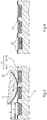
- the rolling of the rider roller 11 on the anilox roller 2 is shown in a greatly simplified representation, the components involved not being shown in their true size ratio to one another for better understanding.
- the anilox roller 2 has an anilox surface 17 which extends in a circular ring over the entire circumference of the anilox roller 2, which cannot be seen in the section shown.
- the screen surface 17 does not have to extend over the entire axial length of the screen roller 2 .
- the grid surface 17 consists of a groove 18 and a web 19, which delimits the groove 18 and form the side walls.
- the groove 18 and the web 19 run parallel to one another in helical form or helically around the axis of rotation of the anilox roller 2, which axis of rotation is perpendicular to the plane of the image figure 3 is oriented.
- the direction of extension of the groove 18 and the ridge 19 is oblique relative to the plane of the image figure 3 .
- the grid structure formed by the groove 18 and the web 19 resembles a thread, with figure 3 three courses of this "thread" are shown. Such a grid structure is also referred to as a hash.
- the ridge 19 forms a raised surface portion 20 of the grid surface 17 and the groove 18 a recessed surface portion 21 and both surface portions 20, 21 together result in the entire grid surface 17.
- the grid structure would have the form of a multiple thread and the raised surface portion 20 would be formed by the two webs 19 together and the recessed surface portion 21 by the two grooves 18 together .
- the raised surface portion 20 is at least 10% of the entire grid surface 17, so that the recessed surface portion 21 is at most 90% of the grid surface 17.
- the raised surface area 20 - the so-called contact area - can be more than 15% and less than 35% of the entire grid area 17, with a ridge width S of the ridge corresponding to 15% to 35% of a cell width Z, which is the sum of the ridge width S and a Groove width R of the groove 18 is.
- figure 3 shows that the rider roller 11, when rolling over the groove 18, removes color from this and, after a few revolutions, has a closed color film 22 on its peripheral surface.
- the rider roller 11 not only removes ink from the groove 18, but also deposits the extracted ink again on the roof surface of the web 19 due to the splitting back, so that the entire screen surface 17 including its raised surface area 20 is colored after the rider roller 11 has been rolled over it is like this in figure 4 is shown.
- the amount of ink 23 deposited on the web 19 has the effect that the anilox surface 17 of the anilox roller 2 is in principle completely covered with ink and correspondingly more ink is transferred to the inking roller 3 .
- the anilox roller 2 can thus transfer more ink to the inking roller 3 per unit area of the anilox surface 17 than would be possible without the rider roller 11 .
- the rider roller 11 is driven in rotation exclusively by the anilox roller 2, i.e. there is no auxiliary drive provided specially for the rider roller 11 and there is no other roller apart from the anilox roller 2 that rests on the rider roller 11 and this drives via peripheral surface friction.
- the rubber covering of the rider roller 11 presses into the grid structure of the anilox roller 2 somewhat due to the roller pressure in the nip of the two rollers 2, 11, which increases the friction and the rider roller 11 runs with the anilox roller 2 with virtually no slippage.
- the rider roller 11 does not carry out any axial reciprocating movement, because such an oscillating movement would impair the desired build-up of color on the roof surface of the web 19.
- FIG 5 a diagram is shown whose ordinate represents the color density of the color black in the printed image.
- the bar on the left in the diagram represents the density adjustment range that is achieved in the first printing operating mode using the rider roller 11 and ranges from 1.82 to 2.41.
- the color density can be adjusted within this range solely by increasing or reducing the temperature control of the anilox roller 2 .
- An existing temperature control for the anilox roller 2 with a temperature control circuit, in which the anilox roller 2 is involved, is for reasons of graphical simplification in the Figures 1 and 2 not shown.
- FIG 2 a second printing operating mode is shown, in which the rider roller 11 is switched off from the anilox roller 2 and is passive.
- the actuator 15 linked to the bearing lever 14 is retracted to such an extent that the spring 16 is no longer able to press the rider roller 11 against the anilox roller 2 and the two rollers 2, 11 are out of contact with one another.
- the second print mode of operation is intended for a print job that requires a lower color density than the print job for which the first print mode of operation is intended.
- the right bar in the chart according to figure 5 represents the density adjustment range in the second printing mode of operation, this density adjustment range being from 1.48 to 2.06.
- the density adjustment range in the second print operating mode extends down to lower color density values than the density adjustment range in the first print operating mode (left bar).
- the ink transfer from the anilox roller 2 to the inking roller 3 can be adjusted solely by changing the anilox roller temperature control. Increasing the anilox roller temperature reduces the ink viscosity and correspondingly more ink is transferred from the anilox roller 2 to the pick-up device (ink applicator roller 3). By lowering the anilox roller temperature, the viscosity of the fluid (ink) is increased and accordingly less fluid is transferred to the pick-up device.
- print jobs can be printed in this mode that require such a low ink density that the first printing mode is no longer suitable, for the following reason:
- the temperature of the anilox roller 2 would have to be lowered so much in order to achieve the low color density that condensation problems would occur on the anilox roller 2, through which the print quality would be impaired. It is therefore advantageous that the anilox roller temperature can be kept above the critical lower limit by switching off the rider roller 11 .
- the amount of fluid transferred determines the color density that can be measured in the printed image on the substrate.
- An advantage of the method according to the invention is that the density control range represented by the right-hand bar is expanded by switching on the rider roller 11 by the density control range represented by the left-hand value bar, which means that changing the anilox roller 2 to change the effective scoop volume of the anilox roller 2 is less necessary and the machine downtimes associated with changing anilox rollers can be minimized.
- figure 6 1 shows the flow chart of the operating method of the printing machine 1, with the steps of the program running in the control device 24 corresponding to this flow chart.
- a first method step 101 the color density or coloring is measured.
- step 104 If it is determined in the fourth step 104 that the rider roller 11 is not yet in contact with the anilox roller 2, then in a sixth step 106 the rider roller 11 is placed against the anilox roller 2 and the anilox roller temperature is reduced. Then, in a seventh step 107, continuous printing begins.
- an eighth step 108 it is decided whether the coloration is too high or not. If the inking is not too great, then continuous printing begins in the seventh step 107 . However, if the measurement in the eighth step 108 shows that the coloring is too high, then checked or decided in a ninth step whether the current anilox roller temperature already corresponds to the lower control limit for the anilox roller temperature or not. If the lower setting limit has already been reached, then in a tenth step 110 it is checked whether the rider roller 11 is already in contact with the anilox roller 2 or not.
- step 111 the rider roller 11 is switched off from the anilox roller 2, that is, from the first printing operating mode ( figure 1 ) to the second printing operation mode ( figure 2 ) is changed and the anilox roller temperature is increased on the temperature control device. Then the continuous printing 107 is started.
- the anilox roller temperature is adjusted by lowering the anilox roller temperature. Then the continuous printing 107 is started.
- the temperature of the anilox roller is adjusted by increasing the anilox roller temperature. After that, production run 107 will also begin. If it is determined in the tenth step 110 that the rider roller 11 is not in contact with the anilox roller 2, i.e. that the anilox inking unit is operated in the second printing operating mode, then in a thirteenth step 113 the anilox roller is replaced (for a replacement anilox roller with a lower scoop volume) and/or the color adjusted, for example replaced by another color with a different pigmentation. Then the continuous printing 107 is started.
Description
Die vorliegende Erfindung betrifft ein Verfahren zum Betreiben einer Druckmaschine nach dem Oberbegriff von Anspruch 1.The present invention relates to a method for operating a printing press according to the preamble of claim 1.
In der
In dem Absatz "Zellöffnung" des Artikels "Rasterwalze" auf der Website https://de.wikipedia.org./wiki/Rasterwalze in der Version vom 15.10.2015 steht, dass eine minimale Stegbreite optimal für eine ruhige Einfärbung ist. Der Artikel lehrt somit, dass eine Minimierung des erhabenen Flächenanteils anzustreben ist, damit das Druckbild nicht unruhig ist.In the paragraph "Zell opening" of the article "Anilox roller" on the website https://de.wikipedia.org./wiki/Anilox roller in the version of October 15, 2015, it says that a minimum web width is optimal for smooth inking. The article thus teaches that the aim should be to minimize the raised surface area so that the printed image is not unsteady.
Ein vom genannten Stand der Technik - der Offenlegungsschrift und dem Internet-Artikel - nicht behandeltes Problem ist der sehr eng begrenzte Stellbereich der Farbdichte bei Anilox-Farbwerken. Manche Druckaufträge erfordern eine vergleichsweise hohe Farbdichte. In solchen Fällen wird die Farbübertragung verstärkt, indem die Temperatur der Rasterwalze erhöht wird, die an eine Temperiereinrichtung angeschlossen ist. Die Temperatur der Rasterwalze kann aber nur bis zu einer oberen Grenze erhöht werden, weil bei einem Überschreiten der oberen Grenze die Gefahr der Selbstentzündung von in dem Anilox-Farbwerk verwendeten Waschmitteln bestehen würde. Deshalb bleibt als einzige Möglichkeit, die in der Druckmaschine eingesetzte Rasterwalze durch eine andere zu ersetzen, welche ein größeres Schöpfvolumen hat. Dieser Rasterwalzenwechsel ist aber mit Maschinenstillstandszeiten verbunden.A problem not dealt with by the prior art mentioned - the Offenlegungsschrift and the Internet article - is the very narrow adjustment range of the color density in anilox inking units. Some print jobs require a comparatively high color density. In such cases, ink transfer is enhanced by raising the temperature of the anilox roller, which is connected to a temperature control device. the However, the temperature of the anilox roller can only be increased up to an upper limit, because if the upper limit is exceeded there would be a risk of the detergents used in the anilox inking unit igniting spontaneously. Therefore, the only option left is to replace the anilox roller used in the printing press with another one that has a larger scoop volume. However, this anilox roller change is associated with machine downtimes.
In
In
In
Der vorliegenden Erfindung liegt die Aufgabe zugrunde, ein Verfahren zum Betreiben einer Druckmaschine anzugeben, bei dem durch Rasterwalzenwechsel bedingte Maschinenstillstandszeiten seltener erforderlich sind.The present invention is based on the object of specifying a method for operating a printing press in which machine downtimes caused by changing anilox rollers are required less frequently.
Diese Aufgabe wird durch ein Verfahren mit den Merkmalen des Anspruchs 1 gelöst.This object is achieved by a method having the features of claim 1.
Der Erfindung liegt die Erkenntnis zugrunde, dass sich der Dichtestellbereich eines Anilox-Farbwerks durch das Zusammenwirken der Reiterwalze mit einem hinreichend großen erhabenen Flächenanteil erweitern lässt. Wenn der erhabene Flächenanteil hinreichend groß ist, bewirkt die Reiterwalze nicht nur eine Egalisierung der Farbübertragung, sondern auch eine Erhöhung der Farbübertragung und somit eine Erweiterung des Dichtestellbereichs. Untersuchungen haben ergeben, dass unter praktischen Bedingungen der erhabene Flächenanteil mindestens 10% der Rasterfläche betragen sollte. Dies bedeutet zum Beispiel, dass das Öffnungsbreite-Stegbreite-Verhältnis der Rasterfläche höchstens 9:1 betragen sollte. Das Öffnungsbreite-Stegbreite-Verhältnis wird insbesondere im Falle einer Näpfchen-Rasterung auch als sogenanntes Napf-Steg-Verhältnis bezeichnet.The invention is based on the finding that the density adjustment range of an anilox inking unit can be expanded through the interaction of the rider roller with a sufficiently large raised surface area. If the raised surface area is sufficiently large, the rider roller not only equalizes the ink transfer, but also increases the ink transfer and thus expands the density control range. Investigations have shown that under practical conditions the raised area proportion is at least 10% of the grid area should be. This means, for example, that the ratio of the opening width to the land width of the grid area should not exceed 9:1. The opening width/land width ratio is also referred to as the so-called cell/land ratio, particularly in the case of cell screening.
Beispielsweise kann die Rasterwalze mit einer Lineatur von 90 Linien pro Zentimeter graviert sein und die Gravur eine sogenannte Haschur sein, bei welcher statt der Näpfchen eine oder mehrere in Schraubenlinienform um die Rasterwalze verlaufende Rillen vorhanden sind. Bei der genannten Lineatur beträgt der Rasterabstand bzw. die sogenannte Zellbreite 0,11 mm. Aufgrund unvermeidlicher Fertigungstoleranzen liegt die Rillenbreite (Öffnungsbreite) zwischen 80 µm und 90 µm und liegt die Stegbreite zwischen 20 µm und 30 µm. Das heißt, wenn an einer bestimmten Stelle die Rillenbreite 80 µm beträgt, dann beträgt die zugehörige Stegbreite 30 µm, und wenn an einer anderen Stelle die Rillenbreite 90 µm beträgt, dann beträgt an der zugehörigen Stelle die Stegbreite 20 µm.For example, the anilox roller can be engraved with a line of 90 lines per centimeter and the engraving can be what is known as a hatch, in which instead of the cells there are one or more grooves running in a helical shape around the anilox roller. With the ruling mentioned, the grid spacing or the so-called cell width is 0.11 mm. Due to unavoidable manufacturing tolerances, the groove width (opening width) is between 80 µm and 90 µm and the land width is between 20 µm and 30 µm. That is, if at a certain location the groove width is 80 µm, then the associated land width is 30 µm, and if at another location the groove width is 90 µm, then at the associated location the land width is 20 µm.
In den Unteransprüchen sind vorteilhafte Weiterbildungen des erfindungsgemäßen Verfahrens genannt.Advantageous further developments of the method according to the invention are specified in the dependent claims.
Bei einer Weiterbildung beträgt der erhabene Flächenanteil 15% bis 35% der Rasterfläche. Bei einer weiteren Weiterbildung wird als die Rasterwalze eine Rasterwalze verwendet, bei welcher die Rasterfläche eine Lineatur von höchstens 135 Linien pro Zentimeter aufweist. Bei einer weiteren Weiterbildung wird als die Rasterwalze eine Rasterwalze verwendet, deren Rasterfläche eine Haschurenfläche ist, bei welcher der erhabene Flächenanteil durch einen Steg oder mehrere Stege gebildet wird und der vertiefte Flächenanteil durch eine Rille oder mehrere Rillen gebildet wird und jeder Steg und jede Rille schraubenlinienförmig verläuft.In a development, the raised area is 15% to 35% of the grid area. In a further development, an anilox roller is used as the anilox roller, in which the anilox surface has a ruling of at most 135 lines per centimeter. In a further development, an anilox roller is used as the anilox roller, the anilox surface of which is a hazel surface, in which the raised surface area is formed by a web or several webs and the recessed surface area is formed by a groove or several grooves and each web and each groove is helically shaped runs.
Bei einer weiteren Weiterbildung wird die Reiterwalze in dem ersten Druckbetriebsmodus ausschließlich mit der Rasterwalze in Abrollkontakt gehalten.In a further development, the rider roller is kept in rolling contact exclusively with the anilox roller in the first printing operating mode.
Bei einer weiteren Weiterbildung wird die Reiterwalze in dem ersten Druckbetriebsmodus durch eine Feder in Abrollkontakt mit der Rasterwalze gehalten.In a further development, the rider roller is held in rolling contact with the anilox roller by a spring in the first printing operating mode.
Bei einer weiteren Weiterbildung wird in dem ersten Druckbetriebsmodus die Rotation der Reiterwalze ausschließlich von der Rasterwalze angetrieben, wobei die Rasterwalze die Reiterwalze über Umfangsflächenreibung antreibt.In a further development, in the first printing operating mode the rotation of the rider roller is driven exclusively by the anilox roller, with the anilox roller driving the rider roller via peripheral surface friction.
Bei einer weiteren Weiterbildung wird als die Reiterwalze keine Changierwalze und keine Reiterwalze verwendet, sondern eine axial stillstehende Walze.In a further development, no traversing roller or rider roller is used as the rider roller, but rather an axially stationary roller.
Vorteilhafte Weiterbildungen der Erfindung ergeben sich auch aus der nachfolgenden Beschreibung eines Ausführungsbeispiels und der dazugehörigen Zeichnung, in welcher zeigt:
- Figur 1
- eine Druckmaschine in einem ersten Druckbetriebsmodus mit Abrollkontakt zwischen Reiterwalze und Rasterwalze,
Figur 2- die Druckmaschine aus
Figur 1 in einem zweiten Druckbetriebsmodus ohne Abrollkontakt zwischen Reiterwalze und Rasterwalze, Figur 3- ein Schema der Wirkungsweise der Reiterwalze bei der Entnahme von Farbe aus Haschur-Rillen der Rasterwalze,
- Figur 4
- ein Schema der Rasterwalze mit auf Haschur-Stegen abliegender Farbe nach der in
Figur 3 Figur 5- ein Diagramm mit Dichtestellbereichen des Anilox-Farbwerks im ersten und zweiten Druckbetriebsmodus und
Figur 6- einen Programmablaufplan zur Steuerung des Anilox-Farbwerks.
- figure 1
- a printing press in a first printing operating mode with rolling contact between rider roller and anilox roller,
- figure 2
- the printing press off
figure 1 in a second printing mode without rolling contact between rider roller and anilox roller, - figure 3
- a diagram of the mode of action of the rider roller when removing ink from the Hashur grooves of the anilox roller,
- figure 4
- a scheme of the anilox roller with color lying on haschur bars according to the in
figure 3 shown phase, - figure 5
- a diagram with density adjustment ranges of the anilox inking unit in the first and second printing operating mode and
- figure 6
- a program flow chart for controlling the anilox inking unit.
In den
Die Erfindung ist nicht nur in einem Anilox-Offset-Druckwerk anwendbar, sondern auch in einem Flexodruckwerk. Ein solches Flexodruckwerk kann zum Beispiel als Lackierwerk Bestandteil einer Offsetdruckmaschine sein, die außer dem Flexodruckwerk eine Reihe von Offset-Druckwerken aufweist. Bei dem Flexodruckwerk ist statt der Farbauftragwalze 3 ein Druckformzylinder angeordnet, mit dem die Rasterwalze 2 beim Drucken in Abrollkontakt steht, und bildet dieser Druckformzylinder die Abnahmeeinrichtung. Die Farbauftragwalze 3 und der im Zusammenhang mit dem Offsetdruck genannte Gummituchzylinder entfallen bei dem Flexodruckwerk.The invention can be used not only in an anilox offset printing unit, but also in a flexographic printing unit. Such a flexographic printing unit can be part of an offset printing machine, for example as a varnishing unit, which has a number of offset printing units in addition to the flexographic printing unit. In the flexographic printing unit, instead of the inking
Die Rasterwalze 2 und die Farbauftragwalze 3 werden so aufeinander abgestimmt rotiert, wie es dem in
Im Druckbetrieb dreht sich die Rasterwalze 2 in die Drehrichtung 10. In dieser Drehrichtung nach der Zuführeinrichtung 6 und vor der Farbauftragwalze 3 ist eine Reiterwalze 11 angeordnet. Nach der Farbauftragwalze 3 und vor der Zuführeinrichtung 6 ist eine Walzengruppe 12 angeordnet. Die Reiterwalze 11 hat eine Umfangsfläche aus einem weichen und farbfreundlichen Gummiwerkstoff und ist an ihren beiden Enden jeweils in einem Walzenschloss 13 gelagert, das an einem Lagerhebel 14 angeordnet ist, der durch einen Stellantrieb 15 schwenkbar ist, zum Beispiel durch einen Pneumatikzylinder. Eine Steuereinrichtung 24 steuert den Stellantrieb 15 entsprechend eines in der Steuereinrichtung 24 ablaufenden Programms an.In printing operation, the
Jedes Walzenschloss 13 umfasst eine Feder 16 zum Andrücken der Reiterwalze 11 an die Rasterwalze 2. Dieses Federsystem ist hinsichtlich seiner Nachstellwirkung vorteilhaft, durch welche Durchmesserveränderungen der Reiterwalze 11 kompensiert werden, die durch deren Alterung oder durch einen Walzenwechsel bedingt sind. Der aus Gummi oder einem gummiartigen Kunststoff bestehende Walzenbezug der Reiterwalze 11 kann im Laufe der Zeit schrumpfen oder aufquellen, wodurch sich der Walzendurchmesser ändern kann. Die Reiterwalze 11 kann verschleißbedingt durch eine Ersatzwalze ersetzt werden, deren Durchmesser toleranzbedingt geringfügig von jenem der ursprünglichen Reiterwalze 11 abweicht. Der Walzenbezug der Ersatzwalze kann geringfügig weicher oder härter als der Walzenbezug der ursprünglichen Reiterwalze 11 sein, auch solche Unterschiede in der Kompressibilität der Walzen werden durch das Federsystem ausgeglichen. Die Reiterwalze 11 steht im Druckbetrieb ausschließlich mit der Rasterwalze 2 in Abrollkontakt, das heißt, es liegt keine andere Walze oder kein anderer Zylinder an der Reiterwalze 11 an.Each
In
Würden zwei Stege 19 und zwei Rillen 18 parallel miteinander verlaufen, was ebenfalls möglich wäre, hätte die Rasterstruktur die Form eines mehrgängigen Gewindes und würde der erhabene Flächenanteil 20 durch die beiden Stege 19 zusammen gebildet und der vertiefte Flächenanteil 21 durch die beiden Rillen 18 zusammen gebildet.If two
Der erhabene Flächenanteil 20 beträgt mindestens 10% der gesamten Rasterfläche 17, so dass der vertiefte Flächenanteil 21 höchstens 90% der Rasterfläche 17 beträgt. Beispielsweise kann der erhabene Flächenanteil 20 - der sogenannte Traganteil - mehr als 15% und weniger als 35% der gesamten Rasterfläche 17 betragen, wobei eine Stegbreite S des Steges 15% bis 35% einer Zellbreite Z entspricht, welche die Summe der Stegbreite S und einer Rillenbreite R der Rille 18 ist.The raised surface portion 20 is at least 10% of the
In dem ersten Druckbetriebsmodus wird die Reiterwalze 11 ausschließlich von der Rasterwalze 2 rotativ angetrieben, das heißt, es ist kein extra für die Reiterwalze 11 vorgesehener Hilfsantrieb vorhanden und es ist außer der Rasterwalze 2 keine andere Walze vorhanden, die an der Reiterwalze 11 anliegt und diese über Umfangsflächenreibung antreibt. Der Gummibezug der Reiterwalze 11 drückt sich aufgrund der Walzenpressung im Walzenspalt der beiden Walzen 2, 11 in die Rasterstruktur der Rasterwalze 2 etwas hinein, wodurch die Reibung erhöht wird und die Reiterwalze 11 mit der Rasterwalze 2 quasi schlupffrei mitläuft. Die Reiterwalze 11 führt keine axiale Hin- und Herbewegung aus, weil ein solches Changieren den erwünschten Farbaufbau auf der Dachfläche des Steges 19 beeinträchtigen würde.In the first printing operating mode, the
In
In
Der rechte Balken in dem Diagramm gemäß
Durch das Abschalten der Reiterwalze 11 im zweiten Druckbetriebsmodus können in diesem Druckaufträge gedruckt werden, die eine so geringe Farbdichte erfordern, dass der erste Druckbetriebsmodus nicht mehr geeignet ist, und zwar aus folgendem Grund: Im ersten Druckbetriebsmodus müsste die Temperatur der Rasterwalze 2 so weit abgesenkt werden, um die geringe Farbdichte zu erreichen, dass an der Rasterwalze 2 Kondensatbildungsprobleme auftreten würden, durch welche die Druckqualität beeinträchtigt werden würde. Deshalb ist es vorteilhaft, dass durch das Abschalten der Reiterwalze 11 die Rasterwalzentemperatur über der kritischen unteren Grenze gehalten werden kann. Die Menge des übertragenen Fluids bestimmt die im Druckbild auf dem Bedruckstoff messbare Farbdichte.By switching off the
Ein Vorteil des erfindungsgemäßen Verfahrens ist, dass der durch den rechten Balken repräsentierte Dichtestellbereich durch das Zuschalten der Reiterwalze 11 um den durch den linken Wertebalken repräsentierten Dichtestellbereich erweitert wird, wodurch Wechsel der Rasterwalze 2 zwecks Veränderung des wirksamen Schöpfvolumens der Rasterwalze 2 seltener erforderlich sind und die mit den Rasterwalzenwechseln verbundenen Maschinenstillstandszeiten minimiert werden.An advantage of the method according to the invention is that the density control range represented by the right-hand bar is expanded by switching on the
In
In einem ersten Verfahrensschritt 101 wird die Farbdichte oder Färbung gemessen.In a
In einem zweiten Verfahrensschritt 102 wird entschieden, ob die Färbung zu gering ist oder nicht. Falls die Färbung zu gering ist, wird in einem dritten Schritt 103 entschieden, ob die obere Stellgrenze der Rasterwalzentemperatur bereits erreicht ist oder nicht. Ist die obere Stellgrenze bereits erreicht, wird in einem vierten Schritt 104 entschieden, ob die Reiterwalze 11 bereits an der Rasterwalze 2 anliegt oder nicht. Falls die Reiterwalze 11 bereits an die Rasterwalze 2 angestellt ist, das heißt im ersten Druckbetriebsmodus betrieben wird, wird in einem fünften Schritt die Rasterwalze ausgetauscht (gegen eine Ersatzrasterwalze mit einem höheren Schöpfvolumen) und/oder die verwendete Druckfarbe ausgetauscht, zum Beispiel gegen eine Druckfarbe mit einer höheren Pigmentierung. Wird in dem vierten Schritt 104 festgestellt, dass die Reiterwalze 11 noch nicht an der Rasterwalze 2 anliegt, dann wird in einem sechsten Schritt 106 die Reiterwalze 11 an die Rasterwalze 2 angestellt und die Rasterwalzentemperatur reduziert. Danach wird in einem siebten Schritt 107 mit dem Fortdruck begonnen.In a
Wird in dem zweiten Schritt 102 festgestellt, dass die Färbung nicht zu gering ist, dann wird in einem achten Schritt 108 entschieden, ob die Färbung zu hoch ist oder nicht. Ist die Färbung nicht zu hoch, dann wird mit dem Fortdruck im siebten Schritt 107 begonnen. Ergibt die Messung im achten Schritt 108 jedoch, dass die Färbung zu hoch ist, dann wird in einem neunten Schritt geprüft bzw. entschieden, ob die aktuelle Rasterwalzentemperatur bereits der unteren Stellgrenze für die Rasterwalzentemperatur entspricht oder noch nicht. Ist die untere Stellgrenze bereits erreicht, dann wird in einem zehnten Schritt 110 geprüft, ob die Reiterwalze 11 bereits an der Rasterwalze 2 anliegt oder nicht. Wird bei dieser Prüfung festgestellt, dass die Reiterwalze 11 an der Rasterwalze 2 anliegt, dann wird in einem elften Schritt 111 die Reiterwalze 11 von der Rasterwalze 2 abgestellt, das heißt, vom ersten Druckbetriebsmodus (
Ergibt die im neunten Schritt 109 erfolgende Prüfung, dass die untere Stellgrenze der Rasterwalzentemperatur noch nicht erreicht ist, dann wird in einem zwölften Schritt 112 die Rasterwalzentemperatur angepasst, indem die Rasterwalzentemperatur abgesenkt wird. Danach wird mit dem Fortdruck 107 begonnen.If the check carried out in the
Ergibt die in dem dritten Schritt 103 erfolgende Prüfung, dass die obere Stellgrenze der Rasterwalzentemperatur noch nicht erreicht ist, dann wird in dem zwölften Schritt 112 die Temperatur der Rasterwalze angepasst, indem die Rasterwalzentemperatur erhöht wird. Auch danach wird mit dem Fortdruck 107 begonnen. Falls in dem zehnten Schritt 110 festgestellt wird, dass die Reiterwalze 11 nicht an der Rasterwalze 2 anliegt, das heißt, dass das Anilox-Farbwerk im zweiten Druckbetriebsmodus betrieben wird, dann wird in einem dreizehnten Schritt 113 die Rasterwalze ausgewechselt (gegen eine Ersatzrasterwalze mit einem geringeren Schöpfvolumen) und/oder die Farbe angepasst, zum Beispiel durch eine andere Farbe mit einer anderen Pigmentierung ersetzt. Danach wird der Fortdruck 107 begonnen.If the check carried out in the
- 11
- Druckmaschineprinting press
- 22
- Rasterwalzeanilox roller
- 33
- Farbauftragwalzeinking roller
- 44
- Druckformzylinderplate cylinder
- 55
- Feuchtwerkdampening system
- 66
- Zuführeinrichtungfeeding device
- 77
- Behältercontainer
- 88th
- Rakelmesserdoctor blade
- 99
- Schwenkrückwandswiveling rear panel
- 1010
- Drehrichtungdirection of rotation
- 1111
- Reiterwalzerider roller
- 1212
- Walzengrupperoller group
- 1313
- Walzenschlossroller lock
- 1414
- Lagerhebelbearing lever
- 1515
- Stellantriebactuator
- 1616
- Federfeather
- 1717
- Rasterflächegrid area
- 1818
- Rillegroove
- 1919
- Stegweb
- 2020
- Erhabener FlächenanteilRaised surface area
- 2121
- Vertiefter FlächenanteilDeeper surface area
- 2222
- Farbfilmcolor film
- 2323
- Farbmengeamount of paint
- 2424
- Steuereinrichtungcontrol device
- 25 bis 10025 to 100
- --
- 101 bis 113101 to 113
- Verfahrensschrittprocess step
- RR
- Rillenbreitegroove width
- SS
- Stegbreitebridge width
- ZZ
- Zellbreitecell width
Claims (8)
- Method of operating a printing press (1) comprising an anilox roller (2), a supply device (6) for supplying a fluid to the anilox roller (2), a takeoff device for taking the fluid off the anilox roller (2), and a rider roller (11), wherein the anilox roller (2) has a screen surface (17) consisting of a raised surface portion (20) and a recessed surface portion (21), the takeoff device (3) is a roller (3) or a cylinder, and the rider roller (11) is arranged downstream of the supply device (6) and upstream of the takeoff device in the direction of rotation (10) of the anilox roller (2),
characterized
in that the anilox roller (2) is an anilox roller (2) with a raised surface portion (20) amounting to a minimum of 10% of the screen surface (17) and in that in a printing operation in a first printing operation mode, the rider roller (11) is kept in rolling contact with the screen roller (2) and in a printing operation in a second printing operation mode, the rider roller (11) is kept out of rolling contact with the screen roller (2). - Method according to claim 1,
characterized
in that the raised surface portion (20) amounts to 15%-35% of the screen surface (17). - Method according to claim 1 or 2,
characterized
in that the anilox roller (2) is an anilox roller (2) with a screen surface (17) ruling of 135 lines per centimeter at the maximum. - Method according to any one of claims 1 to 3,
characterized
in that the anilox roller (2) is an anilox roller (2) with a tri-helical screen surface (17) in which the raised surface portion (20) is formed by one or more webs (19) and the lowered surface portion (21) is formed by one or more grooves (18), each web (19) and each groove (18) extending helically. - Method according to any one of claims 1 to 4,
characterized
in that in the first printing operation mode, the rider roller (11) is kept in rolling contact exclusively with the anilox roller (2). - The method recited in any one of claims 1 to 5,
characterized
in that in the first printing operation mode, the rider roller (11) is kept in rolling contact with the anilox roller (2) by a spring (16). - Method according to any one of claims 1 to 6,
characterized
in that in the first printing operation mode, the rotation of the rider roller (11) is driven exclusively by the anilox roller (2), the anilox roller (2) driving the rider roller (11) by circumferential surface friction. - Method according to any one of claims 1 to 7,
characterized
in that the rider roller (11) is not a distributor roller but an axially stationary roller (11).
Applications Claiming Priority (1)
| Application Number | Priority Date | Filing Date | Title |
|---|---|---|---|
| DE102015222908.4A DE102015222908A1 (en) | 2015-11-20 | 2015-11-20 | Method for operating a printing machine |
Publications (2)
| Publication Number | Publication Date |
|---|---|
| EP3170665A1 EP3170665A1 (en) | 2017-05-24 |
| EP3170665B1 true EP3170665B1 (en) | 2022-03-30 |
Family
ID=57153383
Family Applications (1)
| Application Number | Title | Priority Date | Filing Date |
|---|---|---|---|
| EP16194540.7A Active EP3170665B1 (en) | 2015-11-20 | 2016-10-19 | Method for operating a printing press having an anilox roller |
Country Status (3)
| Country | Link |
|---|---|
| EP (1) | EP3170665B1 (en) |
| CN (1) | CN106985513B (en) |
| DE (1) | DE102015222908A1 (en) |
Citations (1)
| Publication number | Priority date | Publication date | Assignee | Title |
|---|---|---|---|---|
| US4862799A (en) * | 1987-11-13 | 1989-09-05 | Rockwell International Corporation | Copper coated anodized aluminum ink metering roller |
Family Cites Families (10)
| Publication number | Priority date | Publication date | Assignee | Title |
|---|---|---|---|---|
| DE10144563A1 (en) | 2001-09-11 | 2003-03-27 | Heidelberger Druckmasch Ag | Printing press and method for operating an inking unit |
| DE102006004568A1 (en) | 2006-02-01 | 2007-08-02 | Koenig & Bauer Aktiengesellschaft | Short inking unit for print machine has leveling roller located between spot where ink is admitted and contact gap between screen roller and ink application roller in relation to turning direction of screen roller |
| DE102007041203A1 (en) * | 2006-10-11 | 2008-04-24 | Man Roland Druckmaschinen Ag | Short inking unit for a processing machine |
| DE102007059912A1 (en) * | 2007-12-12 | 2009-06-18 | Koenig & Bauer Aktiengesellschaft | Printing unit for rotary printing press, has inking device cooperative with cylinder, and inking device roller assigned to chamber doctor blade as ink reservoir, where blade is divided into two or more partial chambers with divider seals |
| PT2284007E (en) * | 2007-12-21 | 2015-10-26 | Apex Europ B V | Method and apparatus for forming an anilox roll |
| DE102008043957A1 (en) * | 2008-11-21 | 2010-05-27 | Koenig & Bauer Aktiengesellschaft | Anilox roller for inking unit, has layer forming surface of roller and consisting of ceramic material e.g. tungsten carbide, and recesses stochastically distributed over surface of roller |
| CN101817252B (en) * | 2010-04-08 | 2012-01-25 | 云南侨通包装印刷有限公司 | Ceramic anilox water channeling roll and manufacturing method |
| CN201889960U (en) * | 2010-11-11 | 2011-07-06 | 上海运城制版有限公司 | Snakelike halftonedot ceramic anilox roller |
| WO2014162994A1 (en) * | 2013-04-04 | 2014-10-09 | 株式会社小森コーポレーション | Ink-feeding roller and manufacturing method therefor |
| DE102014225559A1 (en) * | 2014-01-23 | 2015-07-23 | Heidelberger Druckmaschinen Ag | anilox roller |
-
2015
- 2015-11-20 DE DE102015222908.4A patent/DE102015222908A1/en not_active Withdrawn
-
2016
- 2016-10-19 EP EP16194540.7A patent/EP3170665B1/en active Active
- 2016-10-26 CN CN201610944501.4A patent/CN106985513B/en active Active
Patent Citations (1)
| Publication number | Priority date | Publication date | Assignee | Title |
|---|---|---|---|---|
| US4862799A (en) * | 1987-11-13 | 1989-09-05 | Rockwell International Corporation | Copper coated anodized aluminum ink metering roller |
Also Published As
| Publication number | Publication date |
|---|---|
| CN106985513B (en) | 2020-05-22 |
| DE102015222908A1 (en) | 2017-06-08 |
| CN106985513A (en) | 2017-07-28 |
| EP3170665A1 (en) | 2017-05-24 |
Similar Documents
| Publication | Publication Date | Title |
|---|---|---|
| EP0064270B1 (en) | Inking unit | |
| DE2526466A1 (en) | PAINT APPLICATION DEVICE FOR A GRAVURE PRINTING MACHINE | |
| DE19731003B4 (en) | Short inking | |
| EP2703162B1 (en) | Method and device for printing printed material | |
| EP1013418B1 (en) | Inking unit | |
| EP2019753A2 (en) | Assemblies in the printing unit of a rotary press | |
| EP2242651A2 (en) | Rotary flat-bed printing machine | |
| EP1820648B1 (en) | Inking system and method for determination of a configuration status of the same | |
| DE2259085A1 (en) | INK UNIT FOR FLAT PRINTING MACHINES | |
| WO2007134919A1 (en) | Inking unit of a rotary press, comprising a film roller | |
| DE102006041881B4 (en) | Ink metering device of a printing unit and method for controlling the ink metering device | |
| EP1291177B1 (en) | Device for controlling the tranfer of a liquid between two rollers | |
| DE10057051B4 (en) | Method for starting a printing press | |
| EP3170665B1 (en) | Method for operating a printing press having an anilox roller | |
| DE102005013634A1 (en) | Method for operating a printing press | |
| WO2003047864A2 (en) | Device for inking a roller | |
| DE102006042590B4 (en) | Rotary printing machine with at least one color flow separation roller having inking unit | |
| DE69834752T2 (en) | COLOR ACCESSORIES FOR PRINTERS | |
| DE202004006800U1 (en) | Print roller has print zones separated by grooves with profiled edges and with profiled end shoulders to prevent lateral spread of ink into grooves | |
| DE4314426A1 (en) | Method for setting the ink quantity in vibrator inking units of printing machines, in particular sheet-fed offset printing machines, and an appropriately designed vibrator inking unit | |
| DE19727387C1 (en) | Ink feed control device for printing press | |
| EP2090431B1 (en) | Method and apparatus for controlling a dampening unit in a rotary printing press | |
| EP1817167B1 (en) | Gravure printing unit with a doctor for the printing cylinder gravure printing machine and method for exchange of a printing cylinder | |
| DE10241739A1 (en) | Multi-color printing unit has ink storage so meniscus lies above doctor blade wiper edge as adjoining notched roller center angle region at maximum angle to horizontal above and below. | |
| DE102006048329A1 (en) | Paint dosing device for an inking unit |
Legal Events
| Date | Code | Title | Description |
|---|---|---|---|
| PUAI | Public reference made under article 153(3) epc to a published international application that has entered the european phase |
Free format text: ORIGINAL CODE: 0009012 |
|
| STAA | Information on the status of an ep patent application or granted ep patent |
Free format text: STATUS: THE APPLICATION HAS BEEN PUBLISHED |
|
| AK | Designated contracting states |
Kind code of ref document: A1 Designated state(s): AL AT BE BG CH CY CZ DE DK EE ES FI FR GB GR HR HU IE IS IT LI LT LU LV MC MK MT NL NO PL PT RO RS SE SI SK SM TR |
|
| AX | Request for extension of the european patent |
Extension state: BA ME |
|
| STAA | Information on the status of an ep patent application or granted ep patent |
Free format text: STATUS: REQUEST FOR EXAMINATION WAS MADE |
|
| 17P | Request for examination filed |
Effective date: 20171124 |
|
| RBV | Designated contracting states (corrected) |
Designated state(s): AL AT BE BG CH CY CZ DE DK EE ES FI FR GB GR HR HU IE IS IT LI LT LU LV MC MK MT NL NO PL PT RO RS SE SI SK SM TR |
|
| RAP1 | Party data changed (applicant data changed or rights of an application transferred) |
Owner name: HEIDELBERGER DRUCKMASCHINEN AG |
|
| STAA | Information on the status of an ep patent application or granted ep patent |
Free format text: STATUS: EXAMINATION IS IN PROGRESS |
|
| 17Q | First examination report despatched |
Effective date: 20200724 |
|
| STAA | Information on the status of an ep patent application or granted ep patent |
Free format text: STATUS: EXAMINATION IS IN PROGRESS |
|
| RAP1 | Party data changed (applicant data changed or rights of an application transferred) |
Owner name: HEIDELBERGER DRUCKMASCHINEN INTELLECTUAL PROPERTY AG & CO. KG |
|
| GRAP | Despatch of communication of intention to grant a patent |
Free format text: ORIGINAL CODE: EPIDOSNIGR1 |
|
| STAA | Information on the status of an ep patent application or granted ep patent |
Free format text: STATUS: GRANT OF PATENT IS INTENDED |
|
| INTG | Intention to grant announced |
Effective date: 20211124 |
|
| GRAS | Grant fee paid |
Free format text: ORIGINAL CODE: EPIDOSNIGR3 |
|
| GRAA | (expected) grant |
Free format text: ORIGINAL CODE: 0009210 |
|
| STAA | Information on the status of an ep patent application or granted ep patent |
Free format text: STATUS: THE PATENT HAS BEEN GRANTED |
|
| AK | Designated contracting states |
Kind code of ref document: B1 Designated state(s): AL AT BE BG CH CY CZ DE DK EE ES FI FR GB GR HR HU IE IS IT LI LT LU LV MC MK MT NL NO PL PT RO RS SE SI SK SM TR |
|
| REG | Reference to a national code |
Ref country code: GB Ref legal event code: FG4D Free format text: NOT ENGLISH |
|
| REG | Reference to a national code |
Ref country code: CH Ref legal event code: EP |
|
| REG | Reference to a national code |
Ref country code: AT Ref legal event code: REF Ref document number: 1478822 Country of ref document: AT Kind code of ref document: T Effective date: 20220415 |
|
| REG | Reference to a national code |
Ref country code: DE Ref legal event code: R096 Ref document number: 502016014696 Country of ref document: DE |
|
| REG | Reference to a national code |
Ref country code: IE Ref legal event code: FG4D Free format text: LANGUAGE OF EP DOCUMENT: GERMAN |
|
| REG | Reference to a national code |
Ref country code: LT Ref legal event code: MG9D |
|
| PG25 | Lapsed in a contracting state [announced via postgrant information from national office to epo] |
Ref country code: SE Free format text: LAPSE BECAUSE OF FAILURE TO SUBMIT A TRANSLATION OF THE DESCRIPTION OR TO PAY THE FEE WITHIN THE PRESCRIBED TIME-LIMIT Effective date: 20220330 Ref country code: RS Free format text: LAPSE BECAUSE OF FAILURE TO SUBMIT A TRANSLATION OF THE DESCRIPTION OR TO PAY THE FEE WITHIN THE PRESCRIBED TIME-LIMIT Effective date: 20220330 Ref country code: NO Free format text: LAPSE BECAUSE OF FAILURE TO SUBMIT A TRANSLATION OF THE DESCRIPTION OR TO PAY THE FEE WITHIN THE PRESCRIBED TIME-LIMIT Effective date: 20220630 Ref country code: LT Free format text: LAPSE BECAUSE OF FAILURE TO SUBMIT A TRANSLATION OF THE DESCRIPTION OR TO PAY THE FEE WITHIN THE PRESCRIBED TIME-LIMIT Effective date: 20220330 Ref country code: HR Free format text: LAPSE BECAUSE OF FAILURE TO SUBMIT A TRANSLATION OF THE DESCRIPTION OR TO PAY THE FEE WITHIN THE PRESCRIBED TIME-LIMIT Effective date: 20220330 Ref country code: BG Free format text: LAPSE BECAUSE OF FAILURE TO SUBMIT A TRANSLATION OF THE DESCRIPTION OR TO PAY THE FEE WITHIN THE PRESCRIBED TIME-LIMIT Effective date: 20220630 |
|
| REG | Reference to a national code |
Ref country code: NL Ref legal event code: MP Effective date: 20220330 |
|
| PG25 | Lapsed in a contracting state [announced via postgrant information from national office to epo] |
Ref country code: LV Free format text: LAPSE BECAUSE OF FAILURE TO SUBMIT A TRANSLATION OF THE DESCRIPTION OR TO PAY THE FEE WITHIN THE PRESCRIBED TIME-LIMIT Effective date: 20220330 Ref country code: GR Free format text: LAPSE BECAUSE OF FAILURE TO SUBMIT A TRANSLATION OF THE DESCRIPTION OR TO PAY THE FEE WITHIN THE PRESCRIBED TIME-LIMIT Effective date: 20220701 Ref country code: FI Free format text: LAPSE BECAUSE OF FAILURE TO SUBMIT A TRANSLATION OF THE DESCRIPTION OR TO PAY THE FEE WITHIN THE PRESCRIBED TIME-LIMIT Effective date: 20220330 |
|
| PG25 | Lapsed in a contracting state [announced via postgrant information from national office to epo] |
Ref country code: NL Free format text: LAPSE BECAUSE OF FAILURE TO SUBMIT A TRANSLATION OF THE DESCRIPTION OR TO PAY THE FEE WITHIN THE PRESCRIBED TIME-LIMIT Effective date: 20220330 |
|
| PG25 | Lapsed in a contracting state [announced via postgrant information from national office to epo] |
Ref country code: SM Free format text: LAPSE BECAUSE OF FAILURE TO SUBMIT A TRANSLATION OF THE DESCRIPTION OR TO PAY THE FEE WITHIN THE PRESCRIBED TIME-LIMIT Effective date: 20220330 Ref country code: SK Free format text: LAPSE BECAUSE OF FAILURE TO SUBMIT A TRANSLATION OF THE DESCRIPTION OR TO PAY THE FEE WITHIN THE PRESCRIBED TIME-LIMIT Effective date: 20220330 Ref country code: RO Free format text: LAPSE BECAUSE OF FAILURE TO SUBMIT A TRANSLATION OF THE DESCRIPTION OR TO PAY THE FEE WITHIN THE PRESCRIBED TIME-LIMIT Effective date: 20220330 Ref country code: PT Free format text: LAPSE BECAUSE OF FAILURE TO SUBMIT A TRANSLATION OF THE DESCRIPTION OR TO PAY THE FEE WITHIN THE PRESCRIBED TIME-LIMIT Effective date: 20220801 Ref country code: ES Free format text: LAPSE BECAUSE OF FAILURE TO SUBMIT A TRANSLATION OF THE DESCRIPTION OR TO PAY THE FEE WITHIN THE PRESCRIBED TIME-LIMIT Effective date: 20220330 Ref country code: EE Free format text: LAPSE BECAUSE OF FAILURE TO SUBMIT A TRANSLATION OF THE DESCRIPTION OR TO PAY THE FEE WITHIN THE PRESCRIBED TIME-LIMIT Effective date: 20220330 Ref country code: CZ Free format text: LAPSE BECAUSE OF FAILURE TO SUBMIT A TRANSLATION OF THE DESCRIPTION OR TO PAY THE FEE WITHIN THE PRESCRIBED TIME-LIMIT Effective date: 20220330 |
|
| PG25 | Lapsed in a contracting state [announced via postgrant information from national office to epo] |
Ref country code: PL Free format text: LAPSE BECAUSE OF FAILURE TO SUBMIT A TRANSLATION OF THE DESCRIPTION OR TO PAY THE FEE WITHIN THE PRESCRIBED TIME-LIMIT Effective date: 20220330 Ref country code: IS Free format text: LAPSE BECAUSE OF FAILURE TO SUBMIT A TRANSLATION OF THE DESCRIPTION OR TO PAY THE FEE WITHIN THE PRESCRIBED TIME-LIMIT Effective date: 20220730 Ref country code: AL Free format text: LAPSE BECAUSE OF FAILURE TO SUBMIT A TRANSLATION OF THE DESCRIPTION OR TO PAY THE FEE WITHIN THE PRESCRIBED TIME-LIMIT Effective date: 20220330 |
|
| REG | Reference to a national code |
Ref country code: DE Ref legal event code: R097 Ref document number: 502016014696 Country of ref document: DE |
|
| PG25 | Lapsed in a contracting state [announced via postgrant information from national office to epo] |
Ref country code: DK Free format text: LAPSE BECAUSE OF FAILURE TO SUBMIT A TRANSLATION OF THE DESCRIPTION OR TO PAY THE FEE WITHIN THE PRESCRIBED TIME-LIMIT Effective date: 20220330 |
|
| PLBE | No opposition filed within time limit |
Free format text: ORIGINAL CODE: 0009261 |
|
| STAA | Information on the status of an ep patent application or granted ep patent |
Free format text: STATUS: NO OPPOSITION FILED WITHIN TIME LIMIT |
|
| 26N | No opposition filed |
Effective date: 20230103 |
|
| PG25 | Lapsed in a contracting state [announced via postgrant information from national office to epo] |
Ref country code: SI Free format text: LAPSE BECAUSE OF FAILURE TO SUBMIT A TRANSLATION OF THE DESCRIPTION OR TO PAY THE FEE WITHIN THE PRESCRIBED TIME-LIMIT Effective date: 20220330 Ref country code: MC Free format text: LAPSE BECAUSE OF FAILURE TO SUBMIT A TRANSLATION OF THE DESCRIPTION OR TO PAY THE FEE WITHIN THE PRESCRIBED TIME-LIMIT Effective date: 20220330 |
|
| REG | Reference to a national code |
Ref country code: CH Ref legal event code: PL |
|
| P01 | Opt-out of the competence of the unified patent court (upc) registered |
Effective date: 20230427 |
|
| REG | Reference to a national code |
Ref country code: BE Ref legal event code: MM Effective date: 20221031 |
|
| GBPC | Gb: european patent ceased through non-payment of renewal fee |
Effective date: 20221019 |
|
| PG25 | Lapsed in a contracting state [announced via postgrant information from national office to epo] |
Ref country code: LU Free format text: LAPSE BECAUSE OF NON-PAYMENT OF DUE FEES Effective date: 20221019 |
|
| PG25 | Lapsed in a contracting state [announced via postgrant information from national office to epo] |
Ref country code: LI Free format text: LAPSE BECAUSE OF NON-PAYMENT OF DUE FEES Effective date: 20221031 Ref country code: IT Free format text: LAPSE BECAUSE OF FAILURE TO SUBMIT A TRANSLATION OF THE DESCRIPTION OR TO PAY THE FEE WITHIN THE PRESCRIBED TIME-LIMIT Effective date: 20220330 Ref country code: FR Free format text: LAPSE BECAUSE OF NON-PAYMENT OF DUE FEES Effective date: 20221031 Ref country code: CH Free format text: LAPSE BECAUSE OF NON-PAYMENT OF DUE FEES Effective date: 20221031 |
|
| PG25 | Lapsed in a contracting state [announced via postgrant information from national office to epo] |
Ref country code: BE Free format text: LAPSE BECAUSE OF NON-PAYMENT OF DUE FEES Effective date: 20221031 |
|
| PG25 | Lapsed in a contracting state [announced via postgrant information from national office to epo] |
Ref country code: IE Free format text: LAPSE BECAUSE OF NON-PAYMENT OF DUE FEES Effective date: 20221019 Ref country code: GB Free format text: LAPSE BECAUSE OF NON-PAYMENT OF DUE FEES Effective date: 20221019 |
|
| REG | Reference to a national code |
Ref country code: AT Ref legal event code: MM01 Ref document number: 1478822 Country of ref document: AT Kind code of ref document: T Effective date: 20221019 |
|
| PG25 | Lapsed in a contracting state [announced via postgrant information from national office to epo] |
Ref country code: AT Free format text: LAPSE BECAUSE OF NON-PAYMENT OF DUE FEES Effective date: 20221019 |
|
| PGFP | Annual fee paid to national office [announced via postgrant information from national office to epo] |
Ref country code: DE Payment date: 20231031 Year of fee payment: 8 |
|
| PG25 | Lapsed in a contracting state [announced via postgrant information from national office to epo] |
Ref country code: HU Free format text: LAPSE BECAUSE OF FAILURE TO SUBMIT A TRANSLATION OF THE DESCRIPTION OR TO PAY THE FEE WITHIN THE PRESCRIBED TIME-LIMIT; INVALID AB INITIO Effective date: 20161019 |