EP3170472B1 - Selbstligierendes bracket mit freitragendem verriegelungsträger - Google Patents
Selbstligierendes bracket mit freitragendem verriegelungsträger Download PDFInfo
- Publication number
- EP3170472B1 EP3170472B1 EP16199526.1A EP16199526A EP3170472B1 EP 3170472 B1 EP3170472 B1 EP 3170472B1 EP 16199526 A EP16199526 A EP 16199526A EP 3170472 B1 EP3170472 B1 EP 3170472B1
- Authority
- EP
- European Patent Office
- Prior art keywords
- ligating
- sliding member
- locking
- self
- ligating sliding
- Prior art date
- Legal status (The legal status is an assumption and is not a legal conclusion. Google has not performed a legal analysis and makes no representation as to the accuracy of the status listed.)
- Active
Links
Images


Classifications
-
- A—HUMAN NECESSITIES
- A61—MEDICAL OR VETERINARY SCIENCE; HYGIENE
- A61C—DENTISTRY; APPARATUS OR METHODS FOR ORAL OR DENTAL HYGIENE
- A61C7/00—Orthodontics, i.e. obtaining or maintaining the desired position of teeth, e.g. by straightening, evening, regulating, separating, or by correcting malocclusions
- A61C7/12—Brackets; Arch wires; Combinations thereof; Accessories therefor
- A61C7/28—Securing arch wire to bracket
- A61C7/34—Securing arch wire to bracket using lock pins
-
- A—HUMAN NECESSITIES
- A61—MEDICAL OR VETERINARY SCIENCE; HYGIENE
- A61C—DENTISTRY; APPARATUS OR METHODS FOR ORAL OR DENTAL HYGIENE
- A61C7/00—Orthodontics, i.e. obtaining or maintaining the desired position of teeth, e.g. by straightening, evening, regulating, separating, or by correcting malocclusions
- A61C7/02—Tools for manipulating or working with an orthodontic appliance
-
- A—HUMAN NECESSITIES
- A61—MEDICAL OR VETERINARY SCIENCE; HYGIENE
- A61C—DENTISTRY; APPARATUS OR METHODS FOR ORAL OR DENTAL HYGIENE
- A61C7/00—Orthodontics, i.e. obtaining or maintaining the desired position of teeth, e.g. by straightening, evening, regulating, separating, or by correcting malocclusions
- A61C7/12—Brackets; Arch wires; Combinations thereof; Accessories therefor
- A61C7/28—Securing arch wire to bracket
- A61C7/287—Sliding locks
-
- A—HUMAN NECESSITIES
- A61—MEDICAL OR VETERINARY SCIENCE; HYGIENE
- A61C—DENTISTRY; APPARATUS OR METHODS FOR ORAL OR DENTAL HYGIENE
- A61C7/00—Orthodontics, i.e. obtaining or maintaining the desired position of teeth, e.g. by straightening, evening, regulating, separating, or by correcting malocclusions
- A61C7/12—Brackets; Arch wires; Combinations thereof; Accessories therefor
- A61C7/28—Securing arch wire to bracket
- A61C7/30—Securing arch wire to bracket by resilient means; Dispensers therefor
- A61C7/303—Elastic bands
Definitions
- an archwire applies corrective forces to a patient's teeth in order to move them to an ideal position.
- the archwire may be received in a slot in a bracket's body and secured within the slot's walls by an elastomeric or steel ligature tie applied to each tooth.
- this approach often results in repetitive and prolonged treatment.
- Self-ligating brackets avoid the use of an elastomeric or steel ligature tie, and instead comprise a ligating member, such as a clip, for securing the archwire.
- a ligating member such as a clip
- One advantage of the self-ligating bracket is a much lower friction at the slot-archwire interface, which allows the use of lower force archwires to move teeth, greatly reducing the iatrogenic potential of the treatment. Eliminating or reducing elastomeric and ligature ties also drastically reduces the repetitive work and the time demanded to change the ligatures.
- DE 10 2006 053 215 A1 discloses a bracket having a slide for displacement in a gingival-to-occlusal direction, a slot-shaped recess in the bracket holds a leaf spring which can bend in the displacement direction of the slide.
- US 2011/0086323 A1 discloses a bracket having a bracket body, an occlusal wall, a gingival wall, a channel extending between the occlusal and gingival walls, a sliding element held in a guide of the bracket which can be displaced between closed and open positions, and means for holding the slide in the closed position or open position, wherein the means are integrated in the bracket.
- US 6071118 A discloses a bracket having a transverse archwire slot.
- First and second anterior surfaces of the bracket terminate at the side slot surfaces.
- a ligating slide is guided within a pair of guides to be moveable between a retracted position and a cantilevered position over the archwire slot, and detents are used to hold the ligating slide in position.
- US 2009/004619 A1 discloses a bracket having a ligating sliding member and flexible locking arms.
- aspects of the present invention relate to a self-ligating bracket system comprising a body, an archwire slot receivable for an archwire, and a locking mechanism.
- the locking mechanism isconfigured to allow a ligating sliding member to move between an open position, such that an archwire may be inserted into and/or removed from the archwire slot, and a closed position, such that an archwire is retained within the archwire slot.
- the locking mechanism comprises a ligating sliding member.
- the ligating sliding member comprises protuberances on a face that is adjacent to the archwire slot.
- the face may be substantially planar.
- the face may comprise a housing for the protuberances.
- the ligating sliding member may substantially cover the archwire slot when the ligating sliding member is in the closed position, such that an orthodontic archwire is retained in the slot.
- the concave and convex surfaces may be on the face of the ligating sliding member, which may be located adjacent to the archwire slot.
- the ligating sliding member may be manufactured with a biocompatible material, such as metal alloys (e.g., stainless steel, chromium cobalt, polymers, hybrid polymers, composites, ceramics, hybrid ceramics, and any other material suitable to be used in the oral environment).
- the ligating sliding member may be manufactured by processes such as MIM, CIM, PIM, microcasting, injection molding, 3D printing, SLA (additive manufacturing), stamping and forming, and/or any other process that can produce a highly robust and mechanical member.
- the ligating member may be manufactured with metal, ceramic, composites, hybrid polymers, and/or plastics with biocompatibility and mechanical requisites in order to withstand the forces and chemistry of the oral environment.
- the locking mechanism also comprises a resilient shape cantilever locking blade.
- the cantilever locking blade interacts with the ligating sliding member.
- the locking mechanism may be manufactured individually as components to be mounted on a body of the bracket.
- the locking mechanism may be manufactured by processes such as stamping, forming, forging, injection molding, 3D printing, SLA, and/or as an integral part of the body and/or part of the ligating sliding member.
- manufacturing methods for these versions of bracket bodies and ligating sliding members include MIM, CIM, SLA, 3D printing, microcasting, plastic injection molding, polymer and composite injection molding, and any other known and effective technology utilized in the art.
- the self-ligating bracket system may comprise a body with a bonding base which is configured to be attached to a patient's tooth.
- the body may comprise a housing which is substantially perpendicular to the archwire slot.
- the housing may have, for example, a rectangular recess with the larger width extending in the coronal/apical direction.
- the recess may be located in a lower portion of the body and may be configured to receive part or parts of the locking mechanism, for example, the cantilever locking blade.
- the body may comprise similar or different material characteristics, requisites, and manufacturing processes as the ligating sliding member.
- the body may be manufactured with a biocompatible material, such as metals alloys (e.g., stainless steel, chromium cobalt, polymers, hybrid polymers, composites, ceramics, hybrid ceramics, and any other material suitable to be used in the oral environment).
- the body may be manufactured by processes such as MIM, CIM, PIM, microcasting, injection molding, 3D printing, SLA (additive manufacturing), stamping and forming, and/or any other process that can produce a highly robust and mechanical element.
- the body may be manufactured with metal, ceramic, composites, hybrid polymers, and/or plastics with biocompatibility and mechanical requisites in order to withstand the forces and chemistry of the oral environment.
- the bracket body may comprise at least two upper tie wings and two lower tie wings.
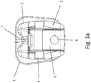
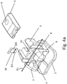
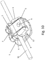
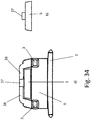
- the self-ligating bracket system may comprise a body with a bonding base (1), two upper tie wings (2) divided by a V-channel (7), and two lower tie wings (3).
- the V- channel may function as a visual aid when positioning the bracket system on a tooth and/or when using an instrument to guide the bracket system when bonding the bracket system to a tooth.
- the lower tie wings (3) may define a sliding path receivable for the ligating sliding member (5).
- the sliding path may be shaped in a generally dovetail or "C" configuration in a cross-sectional view facing toward the center of the system.
- Example aspects of the dovetail shaped sliding path (46) and the "C" configuation (44) may also be seen, for example, in Fig. 38 .
- the archwire slot (4) may be located between the upper tie wings (2) and lower tie wings (3), and may be substantially covered by the ligating sliding member (5) when the ligating sliding member (5) is in the closed position.
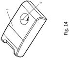
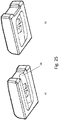
- the ligating sliding member may comprise a through hole (6) which is receivable for an instrument.
- the instrument (17) may positioned in the through hole (6) in order to move the ligating sliding member (5) between open and closed positions.
- the ligating sliding member may also be solid, i.e., devoid of such through hole.
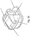
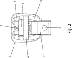
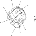
- the ligating sliding member (5) may be moved between an open position (as shown in Fig. 2 ) and a closed position (as shown in Fig. 3 ).
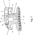
- the body (9) may comprise a platform (8) proximal to the archwire slot (4) and the upper tie wings (2), which may interact with the ligating sliding member (5) when the ligating sliding member (5) is in the closed position.
- the platform (8) may be configured to receive the ligating sliding member (5) in the closed position, and allow the ligating sliding member (5) to interact with the body (9).
- the body (9) may comprise a housing (11) configured to receive a cantilever locking blade (10).
- the housing (11) may be configured such that a face (101) of the cantilever locking blade (10) is parallel to the length of the archwire slot (4), that is, in direction [D1].
- the face (101) has a width corresponding to the width [D3] of the cantilever locking blade (10).
- the housing may be configured such that the face (101) of the cantilever locking blade (10) extends in a direction perpendicular to the length of the archwire slot (4).
- this configuration may allow the cantilever locking blade (10) to move in the mesial and/or distal direction (i.e., parallel to the length of the archwire slot (4)).
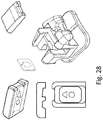
- the cantilever locking blade (10) may comprise a curved tab that may be configured to interact with the ligating sliding member (5).
- the cantilever locking blade (10) may interact with the ligating sliding member (5), such that the cantilever locking blade (10) is housed in a concave housing (15) on the face of the ligating sliding member (5) that is proximal to the archwire slot when the self ligating member (5) is in the closed position.
- the concave housing (15) may comprise a convex division portion (14) that substantially divides the concave housing (15).
- the concave housing (15) may also comprise a locking wall (13).
- the locking wall (13) may be substantially 90° (e.g., +/- 5%) and may interact with the cantilever locking blade (10) when the ligating sliding member (5) is in the open position. The interaction between the cantilever locking blade (10) and the locking wall (13) may at least prevent the ligating sliding member from involuntarily or accidentally being removed from the body (9).
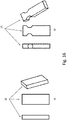
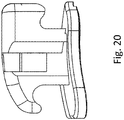
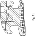
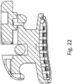
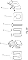
- aspects of the present disclosure may include several embodiments of the cantilever locking blade.
- the cantilever locking blade may be a substantially straight blade (in its planar lengthwise direction) with recesses therein (19) or without recesses (18).
- the cantilever locking blade may comprise a curved locking tab with recesses therein (21) or without recesses therein (20).
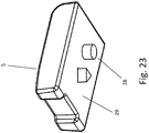
- a cantilever locking blade (10a) may be used that is configured in a generally "U" cross-sectional shape.
- the "U" shaped cantilever locking blade may be configured to deflect force, for example, from the ligating sliding member.
- the deflected force may at least partially force the arms of the "U" shaped cantilever locking blade laterally and in a direction parallel to the archwire slot, such as during assembly and/or use of the the self-ligating bracket system.
- the "U" shaped cantilever locking blade may comprise a variety of shapes.
- the "U" shaped cantilever locking blade may be shaped with substantially sharp corners (10b) and/or may be shaped with substantially rounded corners (10c).
- each arm of the "U" shaped cantilever locking blade may comprise an inwardly extending locking tab (10d).
- the inwardly extending locking tab may at least partially provide the "U" shaped cantilever locking blade with the ability to deflect as a force, for example, from the ligating sliding member, is applied.
- the arms may flex laterally in opposite directions and parallel to the archwire slot, while concomitantly, the locking tabs may be pushed towards the archwire slot and perpendicular to the deflection of the arms, when the "U" shaped locking blade is inserted into the self-ligating bracket system.
- the "U" shaped cantilever locking blade (10f) may comprise a radius section (22) that may join the vertical arms of the "U” shape to a flat segment (23).
- the flat segment (23) may be configured to be received in a housing (11).
- the housing (11) may be configured according to the description herein.
- the radius (22) and the flat segment (23) may at least partially allow the cantilever locking blade (10f) to be flexible in all or a wide range of directions.
- the cantilever locking blade may be flexible in several and/or all or most planes of spaces.
- the arms of the cantilever locking blade may be configured to flex laterally in opposite directions, and parallel to the archwire slot (24).
- the cantilever locking blade may be configured to move perpendicular to the archwire slot (25) during assembly.
- locking tabs on the arms of the cantilever locking blade may be configured to flex perpendicular to the deflection of the arms, thereby allowing the cantilever locking blade to move in a generally rotational fashion (26) during assembly.
- the cantilever locking blade may be flexible in all or numerous planes of space (27).
- the ligating sliding member (5) may comprise one or more protuberances (28).
- each of the protuberances may be rounded or have a polygonal cross-sectional shape in the extending direction from a surface (29) of the sliding member (5).
- the one or protuberances may each have the same shape or differing shapes.
- the ligating sliding member (5) may comprise one round protuberance and one triangular protuberance.
- the protuberances may be located on the face of ligating sliding member (5) that is proximal to the archwire slot when assembled within the self-ligating bracket system.
- the face of the ligating sliding member (5) that is proximal to the archwire slot may have a generally flat surface (29).
- the protuberances (28) may be located in a recess (30) of the ligating sliding member.
- the recess may comprise a frontal opening (31).
- the frontal opening (31) may allow the ligating sliding member (5) and the body of the bracket to be assembled without the ligating sliding member (5) deflecting the cantilever locking blade towards the archwire slot.
- the one or more protuberances may be configured to interact with the cantilever locking blade. According to some aspects, interaction between the cantilever locking blade and the one or more protuberances may at least partially prevent the ligating sliding member from involuntarily or accidentally being removed from the body, and/or involuntarily or accidentally being moved between open and closed positions.
- Fig. 36a - Fig. 36c show the face of an example ligating sliding member (5) according to the invention that is configured to be proximal to an archwire slot.
- the ligating sliding member (5) comprises protuberances (36).
- the protuberances (36) may be round in cross-section, have three dimensional polygonal shape, and/or a combination thereof.
- the protuberances (36) may extend toward a centerline of the ligating sliding member (5) (e.g., inwardly within the interior of ligating sliding member (5)).
- Fig. 36a - Fig. 36c show an example the progression of the ligating sliding member (5) from a closed position ( Fig. 36a ) to an open position ( Fig. 36c ).
- the flexible locking arms (45) of the cantilever locking blade are configured to deflect towards a centerline of the ligating sliding member (5), such as via protuberances (36), as the ligating sliding member (5) transverses the cantilever locking blade, and then return to their original positions, as the ligating sliding member (5) slides between open and closed positions.
- the flexible locking arms (45) may return to their original position when the ligating sliding member (5) is between closed and open positions (see, for example, Fig.
- the ligating sliding member (5) when the ligating sliding member is in the open position, the flexible locking arms (45) may be positioned between a protuberance (36) and a locking wall (13). In this manner, the ligating sliding member (5) may be locked such that it is retained within the body of the bracket.
- the protuberances (36) when the ligating member (5) is in the closed position, the protuberances (36) may prevent the ligating sliding member (5) from inadvertently moving to the open position, and/or such position may "lock" the ligating sliding member (5) in the closed position.
- the recess and/or protuberances of the ligating sliding member may comprise several variations of geometry.
- Fig. 37 shows an example of an alternative geometry of the ligating sliding member (5).
- the ligating sliding member (5) and the protuberances (36) thereon may function substantially similarly to the corresponding features of the ligating sliding member (5) described in Fig. 36 .
- the bracket body (9) may comprise a flexible locking bridge (38) as an integral part or section thereof.
- the flexible locking bridge (38) may be flexible, such that the bridge (38) may be displaced by an inserted ligating sliding member (5), for example, by a locking wedge protuberance (37) located upon a portion of the sliding member (5).
- the flexible locking bridge (38) may flex upwardly when the ligating sliding member (5) slides between open and closed positions.
- the flexible locking bridge (38) may be configured to return to (or be biased toward) its original geometry once the ligating sliding member (5) is in the open or closed position.
- the flexible locking bridge (38) may be configured to return to (or tend toward) its original geometry once the ligating sliding member (5) is in the closed position in order to at least partially hold the ligating sliding member (5) in place.
- the bracket of this example embodiment may comprise a plastic, filled plastic, composite, and/or polymer.
- the bracket of this example embodiment may comprise a metal and be configured such that the flexible locking bridge (38) may be plastically deformed by the ligating sliding member and capable of returning to its original geometry, as discussed above.
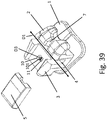
- the ligating sliding member (5) may also comprise a pair of rail guards (41) that may be configured to interact with the lower tie wings (3) such that the ligating sliding member (5) moves straightly between the lower tie wings (3) in the (X) direction between open and closed positions.
- the bracket body (9) may also comprise one or more upper wedge locking ramps (39) and/or one or more lower wedge locking ramps (40), wherein the one or more upper wedge locking ramps (39) and one or more lower wedge locking ramps (40) may be separated by the archwire slot (4).
- the one or more upper wedge locking ramps (39) and/or one or more lower wedge locking ramps (40) may be configured to interact with the ligating sliding member (5). For example, as shown in Fig.
- the underside (104) of ligating sliding member (5) may comprise one or more upper wedge locking ramp recesses (42) and/or one or more lower wedge locking ramp recesses (43) corresponding to the one or more upper wedge locking ramps (39) and one or more lower wedge locking ramps (40) and be configured to interact therewith in order to secure the ligating sliding member (5) in a closed position.
- the cantilever locking blade (10) may be housed in a housing (11) that allows the cantilever locking blade (10) to move in the mesial and/or distal direction (i.e., parallel to the lengthwise direction of the archwire slot (4), such as in direction [D1]).
- the housing (11) may be configured such that the face (101) of the cantilever locking blade (10) is extends in directions perpendicular to the direction of the length of the archwire slot (4).
- the housing may comprise a transversal recess wherein the cantilever locking blade (10) may be biased (e.g., via a spring or lever) to a certain position, but for which the blade 10 may be free to move in the mesial and distal direction, for example, as the ligating sliding member (5) moves between the closed and open positions, as will be explained in more detail below.
- the cantilever locking blade (10) may be biased (e.g., via a spring or lever) to a certain position, but for which the blade 10 may be free to move in the mesial and distal direction, for example, as the ligating sliding member (5) moves between the closed and open positions, as will be explained in more detail below.
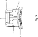
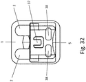
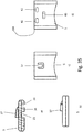
- the ligating sliding member (5) may comprise structural features on the face that is proximal to the cantilever locking blade (10) when in an assembled position (e.g., similar to as shown in Fig. 19 ), the structural features being configured to interoperate with the cantilever locking blade (10).
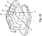
- the sliding ligating member (5) may comprise an angular wall (44) and a locking protuberance (46) that may interoperate with the cantilever locking blade (10) as the ligating sliding member (5) moves between the closed and open positions. For example, as the ligating sliding member (5) is moved past the cantilever locking blade (10) (e.g., in direction [D2] as shown in Fig.
- the angular wall (44) and/or the locking protuberance (46) may cause the cantilever locking blade (10) to move in the mesial or distal direction as the cantilever locking blade (10) contacts them. That is, the cantilever locking blade (10) may be biased to a first biased position, but may move to a second position due to the force of the angular wall (44) and the locking protuberance (46) passing thereby.
- the ligating sliding member (5) may comprise, for example, two indents (47, 45) on either side of the locking protuberance (46).
- the ligating sliding member (5) may comprise a closed position indent (47) and an open position indent (45) that correspond to a closed position and an open position of the ligating sliding member (5), respectively.
- the closed position indent (47) and the open position indent (45) may be configured to house the cantilever locking blade (10) in a first biased position, such that when the angular wall (44) and/or the locking protuberance (46) moves past the cantilever locking blade (10), the cantilever locking blade (10) returns to the first biased position and is locked in either the closed position indent (47) or the open position indent (45) until a user moves the ligating sliding member (5).
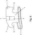
- the ligating sliding member (5) may be moved (e.g., in direction [D2] as shown in Fig. 40 ), such that angular wall (44) is past the cantilever locking blade (10), at which point the cantilever locking blade (10) may become locked in the open position indent (45) via the locking blade 10 moving to the first biased position as shown.
- the ligating sliding member (5) may thereby be locked in the open position.
- the ligating sliding member (5) may be moved further, such that the locking protuberance (46) travels past the cantilever locking blade (10).
- the cantilever locking blade (10) may move from the first biased position in the mesial or distal direction. Once the locking protuberance (46) is past the cantilever locking blade (10), the cantilever locking blade (10) may move back to the first biased position and thereby may become locked in the closed position indent (47).
- the ligating sliding member (5) is locked in the closed position.
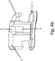
- Fig. 44a and 44b show a top sectional view of the open and closed positions discussed above, respectively.
- Fig. 44a shows the cantilever locking blade (10) locked in open position indent (45), such that the ligating sliding member (5) is locked in the open position.
- Fig. 44b shows the cantilever locking blade (10) locked in closed position indent (47), such that the ligating sliding member (5) is locked in the closed position.
- Example is used herein to mean “serving as an example, instance, or illustration.” Any aspect described herein as “example” is not necessarily to be construed as preferred or advantageous over other aspects. Unless specifically stated otherwise, the term “some” refers to one or more. Combinations such as “at least one of A, B, or C,” “at least one of A, B, and C,” and “A, B, C, or any combination thereof” include any combination of A, B, and/or C, and may include multiples of A, multiples of B, or multiples of C.
- combinations such as “at least one of A, B, or C,” “at least one of A, B, and C,” and “A, B, C, or any combination thereof” may be A only, B only, C only, A and B, A and C, B and C, or A and B and C, where any such combinations may contain one or more member or members of A, B, or C.
Landscapes
- Health & Medical Sciences (AREA)
- Oral & Maxillofacial Surgery (AREA)
- Dentistry (AREA)
- Epidemiology (AREA)
- Life Sciences & Earth Sciences (AREA)
- Animal Behavior & Ethology (AREA)
- General Health & Medical Sciences (AREA)
- Public Health (AREA)
- Veterinary Medicine (AREA)
- Dental Tools And Instruments Or Auxiliary Dental Instruments (AREA)
- Tents Or Canopies (AREA)
Claims (5)
- Selbstligierendes Bracketsystem, umfassend:einen Körper,einen Bogendrahtschlitz (4) zum Aufnehmen eines Bogendrahts undein Arretiersystem,wobei das Arretiersystem ein elastisches Ausleger-Arretierblatt (10) und ein ligierendes Gleitelement (5) mit einer Mittellinie, die parallel zur Gleitrichtung verläuft, umfasst,wobei:das ligierende Gleitelement (5) eine Vielzahl an Höckern (36) aufweist,die Vielzahl an Höckern (36) so ausgebildet sind, dass sie mit dem Ausleger-Arretierblatt (10) zusammenwirken, um das ligierende Gleitelement (5) in einer geschlossenen oder offenen Position festzulegen, unddas elastische Ausleger-Arretierblatt (10) flexible Arretierarme (45) umfasst, dadurch gekennzeichnet, dass die flexiblen Arretierarme (45) zur Auslenkung über die Höcker in Richtung einer Mittellinie des ligierenden Gleitelements ausgebildet sind, wenn das ligierende Gleitelement zwischen der offenen und der geschlossenen Position gleitet.
- Selbstligierendes Bracketsystem nach Anspruch 1, wobei die Vielzahl an Höckern (36) im Querschnitt rund ist oder eine dreidimensionale polygonale Form aufweist.
- Selbstligierendes Bracketsystem nach Anspruch 1, wobei das ligierende Gleitelement ferner eine Aussparung (30) umfasst, in der sich die Vielzahl an Höckern befindet.
- Selbstligierendes Bracketsystem nach Anspruch 3, wobei die Aussparung eine Vorderöffnung (31) umfasst, die es ermöglicht, dass das ligierende Gleitelement (5) und der Körper zusammengebaut werden, ohne dass das ligierende Gleitelement (5) das Ausleger-Arretierblatt in Richtung des Bogendrahtschlitzes auslenkt.
- Selbstligierendes Bracketsystem nach Anspruch 1, wobei der Körper eine Verbindungsbasis (1), zwei obere Befestigungsflügel (2), die durch einen V-Kanal (7) geteilt sind, und zwei untere Befestigungsflügel (3) umfasst.
Applications Claiming Priority (2)
| Application Number | Priority Date | Filing Date | Title |
|---|---|---|---|
| US201562257137P | 2015-11-18 | 2015-11-18 | |
| US15/354,646 US10660729B2 (en) | 2015-11-18 | 2016-11-17 | Self-ligating bracket with cantilever locking beam mechanism and other locking elements for ligating sliding members, and methods of making and use thereof |
Publications (3)
| Publication Number | Publication Date |
|---|---|
| EP3170472A2 EP3170472A2 (de) | 2017-05-24 |
| EP3170472A3 EP3170472A3 (de) | 2017-08-02 |
| EP3170472B1 true EP3170472B1 (de) | 2020-10-28 |
Family
ID=57354201
Family Applications (1)
| Application Number | Title | Priority Date | Filing Date |
|---|---|---|---|
| EP16199526.1A Active EP3170472B1 (de) | 2015-11-18 | 2016-11-18 | Selbstligierendes bracket mit freitragendem verriegelungsträger |
Country Status (3)
| Country | Link |
|---|---|
| US (2) | US10660729B2 (de) |
| EP (1) | EP3170472B1 (de) |
| CA (1) | CA2949006A1 (de) |
Cited By (1)
| Publication number | Priority date | Publication date | Assignee | Title |
|---|---|---|---|---|
| KR20220002947A (ko) * | 2019-05-02 | 2022-01-07 | 월드 클래스 테크놀로지 코퍼레이션 | 편향된 결찰 부재가 있는 치과교정 브래킷 |
Families Citing this family (22)
| Publication number | Priority date | Publication date | Assignee | Title |
|---|---|---|---|---|
| US10660729B2 (en) * | 2015-11-18 | 2020-05-26 | Alexandre Gallo Lopes | Self-ligating bracket with cantilever locking beam mechanism and other locking elements for ligating sliding members, and methods of making and use thereof |
| US10327868B2 (en) * | 2016-09-16 | 2019-06-25 | Ortho Organizers, Inc. | Self ligating orthodontic bracket with coplanar spring |
| USD926993S1 (en) * | 2017-11-21 | 2021-08-03 | World Class Technology Corporation | Ligating member for an orthodontic bracket |
| USD958373S1 (en) | 2017-03-22 | 2022-07-19 | World Class Technology Corporation | Ligating member for an orthodontic bracket |
| CN108992189B (zh) * | 2018-02-08 | 2021-09-24 | 广州欧欧医疗科技有限责任公司 | 自锁正畸托槽 |
| CN108125725B (zh) * | 2018-02-08 | 2021-05-14 | 广州欧欧医疗科技有限责任公司 | 一种滑片自锁托槽 |
| US11872101B2 (en) * | 2018-04-25 | 2024-01-16 | Lightforce Orthodontics, Inc. | Manufacture of patient-specific orthodontic brackets with improved base and retentive features |
| US20240108441A1 (en) * | 2018-04-25 | 2024-04-04 | Lightforce Orthodontics, Inc. | Retentive structure for orthodontic appliance |
| WO2019241252A1 (en) | 2018-06-12 | 2019-12-19 | Lightforce Orthodonitcs, Inc. | Ceramic processing and design for the direct manufacture of customized labial and lingual orthodontic clear aligner attachments |
| US11135037B2 (en) * | 2018-12-17 | 2021-10-05 | Zhejiang Shinye Medical Technology Corp., Ltd. | Self-locking orthodontic bracket |
| CN109481049B (zh) * | 2018-12-17 | 2024-12-20 | 浙江新亚医疗科技股份有限公司 | 自锁正畸托槽 |
| EP3673865A1 (de) * | 2018-12-24 | 2020-07-01 | Orthodontic Research and Development, S.L. | Orthodontische vorrichtung und werkzeug zur positionierung der vorrichtung |
| KR102137000B1 (ko) * | 2019-04-22 | 2020-07-24 | 주식회사 메디센 | 치과 교정용 브라켓 |
| CN111297498A (zh) * | 2020-03-21 | 2020-06-19 | 福建新安格口腔技术发展有限公司 | 正畸托槽和制造正畸托槽的方法 |
| US11407366B2 (en) | 2020-10-30 | 2022-08-09 | Ford Global Technologies, Llc | Bracket for a pillar assembly |
| CN112168390A (zh) * | 2020-11-09 | 2021-01-05 | 梁甲兴 | 适配带状弓丝的正畸自锁系统 |
| US12350123B2 (en) * | 2020-12-23 | 2025-07-08 | Hirsch Dynamics Holding Ag | Self-ligating orthodontic bracket |
| US12016747B2 (en) | 2021-04-16 | 2024-06-25 | Braces On Demand, Inc. | Systems and methods for manufacture of orthodontic appliances |
| US11903790B2 (en) | 2021-04-16 | 2024-02-20 | Braces On Demand, Inc. | Self-ligating orthodontic appliances |
| CN113317893A (zh) * | 2021-07-02 | 2021-08-31 | 长沙奈斯医疗器械有限公司 | 一种滑片式自锁托槽 |
| WO2023058815A1 (ko) * | 2021-10-08 | 2023-04-13 | 주식회사 메디센 | 치열교정 브라켓 |
| JP7763546B1 (ja) * | 2025-02-14 | 2025-11-04 | トミー株式会社 | 歯列矯正ブラケット |
Citations (1)
| Publication number | Priority date | Publication date | Assignee | Title |
|---|---|---|---|---|
| US20090004619A1 (en) * | 2007-06-28 | 2009-01-01 | Ormco Corporation | Self-ligating orthodontic bracket and devices for deploying same |
Family Cites Families (47)
| Publication number | Priority date | Publication date | Assignee | Title |
|---|---|---|---|---|
| US2548864A (en) | 1947-02-07 | 1951-04-17 | Rocky Mountain Metal Products | Orthodontic appliance |
| US2665480A (en) | 1950-10-10 | 1954-01-12 | Baker & Co Inc | Orthodontic device |
| US3775850A (en) | 1971-10-28 | 1973-12-04 | M Northcutt | Orthodontic apparatus |
| US3871096A (en) | 1972-11-08 | 1975-03-18 | Melvin Wallshein | Orthodontic spring clip |
| US4149314A (en) | 1977-02-18 | 1979-04-17 | Nonnenmann Michael J | Orthodontic brackets with pivotal fastenings |
| US4260375A (en) | 1979-12-13 | 1981-04-07 | Melvin Wallshein | Bent wire orthodontic spring clip |
| US4373914A (en) | 1981-10-30 | 1983-02-15 | Colbert Earl J | Orthodontic device |
| US4511331A (en) | 1983-08-08 | 1985-04-16 | Unitek Corporation | Convertible buccal tube/bracket appliance |
| DE8533252U1 (de) | 1985-11-26 | 1986-04-03 | Girse, Martin, 4930 Detmold | Handgerät zum Reinigen verstopfter Abflüsse |
| US4725229A (en) | 1986-06-18 | 1988-02-16 | Ormco Corporation | Orthodontic bracket |
| US4867679A (en) | 1988-04-18 | 1989-09-19 | E. I. Du Pont De Nemours And Company | Orthodontic ligature |
| US5269681A (en) | 1992-05-15 | 1993-12-14 | Degnan Edward V | Integrated ligature and orthodontic bracket |
| US5322435A (en) * | 1992-07-23 | 1994-06-21 | Pletcher Erwin Carroll | Orthodontic bracket |
| US5857850A (en) | 1994-03-07 | 1999-01-12 | Voudouris; John C. | Orthodontic appliance |
| US6358045B1 (en) | 1998-01-14 | 2002-03-19 | Ormco Corporation | Self ligating orthodontic bracket |
| US6042374A (en) | 1998-01-14 | 2000-03-28 | Ormco Corporation | Self ligating orthodontic bracket |
| US6071118A (en) | 1998-02-17 | 2000-06-06 | Damon Family Limited Partnership | Self-ligating orthodontic bracket |
| US5931668A (en) | 1998-03-26 | 1999-08-03 | Birkel; John W. | Method of and apparatus for ligating orthodontic appliances |
| US6325622B1 (en) | 1999-06-11 | 2001-12-04 | 3M Innovative Properties Company | Orthodontic bracket and latch assembly |
| DE29924576U1 (de) | 1999-06-11 | 2003-11-20 | 3M Innovative Properties Co., St. Paul, Minn. | Orthodontisches Bracket und Verriegelungsanordnung |
| US6309214B2 (en) | 1999-09-17 | 2001-10-30 | John W. Birkel | Method of and apparatus for ligating orthodontic appliances |
| JP2001120577A (ja) | 1999-10-27 | 2001-05-08 | Yoneo Sugano | 歯列矯正用ブラケット |
| US6818076B1 (en) | 2000-03-23 | 2004-11-16 | Ormco Corporation | Multi-strand coil spring |
| US7419375B2 (en) | 2002-08-19 | 2008-09-02 | Ormco Corporation | Aesthetic self-ligating orthodontic bracket |
| US7267545B2 (en) * | 2005-01-11 | 2007-09-11 | Ormco Corporation | Self-ligating orthodontic bracket |
| BRMU8600030U (pt) | 2006-01-10 | 2006-12-12 | Alpina Equipamentos Ind Ltda | disposição construtiva introduzida em embarcação recolhedora de óleo |
| BRMU8600342U (pt) | 2006-03-06 | 2007-11-13 | Gilberto Vilanova Queiroz | ligadura ortodÈntica |
| US7704072B2 (en) * | 2006-04-19 | 2010-04-27 | Ormco Corporation | Orthodontic bracket |
| US20090155734A1 (en) * | 2006-04-19 | 2009-06-18 | Damon Dwight H | Orthodontic bracket |
| BRPI0603521A (pt) | 2006-08-24 | 2008-04-15 | Edivaldo Cardoso Pereira | ligadura metálica ortodÈntica pré-ajustada com dobra v |
| DE102006053215B4 (de) * | 2006-11-11 | 2009-10-22 | Bernhard Förster Gmbh | Selbstligierendes Bracket für die Orthodontie |
| US8469704B2 (en) * | 2007-06-28 | 2013-06-25 | Ormco Corporation | Self-ligating orthodontic bracket and devices for deploying same |
| DE202009019038U1 (de) * | 2008-08-13 | 2015-09-16 | Ormco Corp. | Ästhetisches orthodontisches Bracket |
| US20100112508A1 (en) | 2008-11-03 | 2010-05-06 | Alexandre Gallo Lopes | Reversible auto-linked bracket of low profile with double lock |
| DE102008060820A1 (de) * | 2008-12-05 | 2010-06-10 | Bernhard Förster Gmbh | Selbstligierendes Bracket für die Orthodontie |
| DE102009049659B4 (de) | 2009-10-09 | 2014-10-30 | Bernhard Förster Gmbh | Selbstligierendes Bracket für die Orthodontie |
| US20120040302A1 (en) | 2009-10-29 | 2012-02-16 | Shannon Rogers | Self-ligating non-metalic orthodontic bracket |
| BRMU8902352Y1 (pt) | 2009-10-30 | 2017-05-02 | Gallo Lopes Alexandre | braquete autoligável reversível de baixo perfil com dupla trava |
| US8414292B2 (en) | 2010-08-02 | 2013-04-09 | Alexandre Gallo Lopes | Self ligating bracket system |
| BR202012002849Y1 (pt) | 2012-02-08 | 2018-07-31 | Gallo Lopes Alexandre | Bráquete autoligável interativo |
| EP2644150B1 (de) | 2012-03-28 | 2019-01-23 | Orthoarm, Inc. | Aktive selbstlegierende Klammer |
| EP2874561B1 (de) * | 2012-07-23 | 2020-08-26 | 3M Innovative Properties Company | Selbstligierende kieferorthopädische klammer |
| JP2015531303A (ja) * | 2012-10-09 | 2015-11-02 | デンツプライ インターナショナル インコーポレーテッド | 自己結紮歯科矯正ブラケット(self−ligatingorthodonticbracket) |
| US9089386B2 (en) | 2012-11-16 | 2015-07-28 | World Class Technology Corporation | Self-ligating bracket with sliding cover |
| US20150216637A1 (en) * | 2014-02-06 | 2015-08-06 | Seiko Epson Corporation | Dental component, metal powder for powder metallurgy, and method for producing dental component |
| US9901420B2 (en) * | 2014-02-25 | 2018-02-27 | Ormco Corporation | Orthodontic appliances including ferromagnetic shape memory alloys and methods of orthodontic treatment using same |
| US10660729B2 (en) * | 2015-11-18 | 2020-05-26 | Alexandre Gallo Lopes | Self-ligating bracket with cantilever locking beam mechanism and other locking elements for ligating sliding members, and methods of making and use thereof |
-
2016
- 2016-11-17 US US15/354,646 patent/US10660729B2/en active Active
- 2016-11-18 CA CA2949006A patent/CA2949006A1/en active Pending
- 2016-11-18 EP EP16199526.1A patent/EP3170472B1/de active Active
-
2020
- 2020-05-18 US US16/877,051 patent/US11957537B2/en active Active
Patent Citations (1)
| Publication number | Priority date | Publication date | Assignee | Title |
|---|---|---|---|---|
| US20090004619A1 (en) * | 2007-06-28 | 2009-01-01 | Ormco Corporation | Self-ligating orthodontic bracket and devices for deploying same |
Cited By (1)
| Publication number | Priority date | Publication date | Assignee | Title |
|---|---|---|---|---|
| KR20220002947A (ko) * | 2019-05-02 | 2022-01-07 | 월드 클래스 테크놀로지 코퍼레이션 | 편향된 결찰 부재가 있는 치과교정 브래킷 |
Also Published As
| Publication number | Publication date |
|---|---|
| US10660729B2 (en) | 2020-05-26 |
| EP3170472A3 (de) | 2017-08-02 |
| US20200345462A1 (en) | 2020-11-05 |
| CA2949006A1 (en) | 2017-05-18 |
| US11957537B2 (en) | 2024-04-16 |
| US20170135787A1 (en) | 2017-05-18 |
| EP3170472A2 (de) | 2017-05-24 |
Similar Documents
| Publication | Publication Date | Title |
|---|---|---|
| EP3170472B1 (de) | Selbstligierendes bracket mit freitragendem verriegelungsträger | |
| US20110086323A1 (en) | Self-Ligating Bracket for Orthodontics | |
| EP2644150B1 (de) | Aktive selbstlegierende Klammer | |
| AU2020200762B2 (en) | Self-ligating orthodontic bracket | |
| EP2919700B1 (de) | Selbstbindende orthodontische anwendung mit einer gleitabdeckung | |
| EP2783656B1 (de) | Selbstligierende Brackets | |
| US9585733B2 (en) | Orthodontic bracket with angled, curved shutter | |
| EP2777599B1 (de) | Selbstligierendes kieferorthopädisches Bracket | |
| US11633262B2 (en) | Self-ligating bracket for orthodontics | |
| US11298212B2 (en) | Set of brackets for orthodontics | |
| US10123854B2 (en) | Self-ligating orthodontic bracket with positive rotation lock | |
| US20140178831A1 (en) | Self-ligating brackets for orthodontics | |
| EP2730250A1 (de) | Orthodontische Klammer mit einem vorgespannten Gleitstück | |
| EP3367957B1 (de) | Selbstligierende kieferorthopädische klammer | |
| KR102605863B1 (ko) | 결찰 부재를 갖는 자가-결찰 브래킷 | |
| US12127908B2 (en) | Self-ligating bracket for orthodontics | |
| EP3745993B1 (de) | Keramische selbstligierende klammer mit hoher labialer zugfestigkeit | |
| US20170325912A1 (en) | Method and system for an orthodontic device | |
| KR20220002947A (ko) | 편향된 결찰 부재가 있는 치과교정 브래킷 | |
| US20220192792A1 (en) | Set of brackets for orthodontics | |
| CN212547220U (zh) | 一种正畸器具 | |
| JP2019107204A (ja) | 歯列矯正ブラケット | |
| BR102018077335B1 (pt) | Bráquete autoligado de clipe ou membro ligante planar resiliente. |
Legal Events
| Date | Code | Title | Description |
|---|---|---|---|
| PUAI | Public reference made under article 153(3) epc to a published international application that has entered the european phase |
Free format text: ORIGINAL CODE: 0009012 |
|
| STAA | Information on the status of an ep patent application or granted ep patent |
Free format text: STATUS: THE APPLICATION HAS BEEN PUBLISHED |
|
| AK | Designated contracting states |
Kind code of ref document: A2 Designated state(s): AL AT BE BG CH CY CZ DE DK EE ES FI FR GB GR HR HU IE IS IT LI LT LU LV MC MK MT NL NO PL PT RO RS SE SI SK SM TR |
|
| AX | Request for extension of the european patent |
Extension state: BA ME |
|
| PUAL | Search report despatched |
Free format text: ORIGINAL CODE: 0009013 |
|
| AK | Designated contracting states |
Kind code of ref document: A3 Designated state(s): AL AT BE BG CH CY CZ DE DK EE ES FI FR GB GR HR HU IE IS IT LI LT LU LV MC MK MT NL NO PL PT RO RS SE SI SK SM TR |
|
| AX | Request for extension of the european patent |
Extension state: BA ME |
|
| RIC1 | Information provided on ipc code assigned before grant |
Ipc: A61C 7/30 20060101ALI20170627BHEP Ipc: A61C 7/28 20060101AFI20170627BHEP |
|
| STAA | Information on the status of an ep patent application or granted ep patent |
Free format text: STATUS: REQUEST FOR EXAMINATION WAS MADE |
|
| 17P | Request for examination filed |
Effective date: 20180115 |
|
| RBV | Designated contracting states (corrected) |
Designated state(s): AL AT BE BG CH CY CZ DE DK EE ES FI FR GB GR HR HU IE IS IT LI LT LU LV MC MK MT NL NO PL PT RO RS SE SI SK SM TR |
|
| STAA | Information on the status of an ep patent application or granted ep patent |
Free format text: STATUS: EXAMINATION IS IN PROGRESS |
|
| 17Q | First examination report despatched |
Effective date: 20180430 |
|
| GRAP | Despatch of communication of intention to grant a patent |
Free format text: ORIGINAL CODE: EPIDOSNIGR1 |
|
| STAA | Information on the status of an ep patent application or granted ep patent |
Free format text: STATUS: GRANT OF PATENT IS INTENDED |
|
| INTG | Intention to grant announced |
Effective date: 20200508 |
|
| GRAS | Grant fee paid |
Free format text: ORIGINAL CODE: EPIDOSNIGR3 |
|
| GRAA | (expected) grant |
Free format text: ORIGINAL CODE: 0009210 |
|
| STAA | Information on the status of an ep patent application or granted ep patent |
Free format text: STATUS: THE PATENT HAS BEEN GRANTED |
|
| AK | Designated contracting states |
Kind code of ref document: B1 Designated state(s): AL AT BE BG CH CY CZ DE DK EE ES FI FR GB GR HR HU IE IS IT LI LT LU LV MC MK MT NL NO PL PT RO RS SE SI SK SM TR |
|
| REG | Reference to a national code |
Ref country code: GB Ref legal event code: FG4D |
|
| REG | Reference to a national code |
Ref country code: CH Ref legal event code: EP |
|
| REG | Reference to a national code |
Ref country code: DE Ref legal event code: R096 Ref document number: 602016046608 Country of ref document: DE |
|
| REG | Reference to a national code |
Ref country code: AT Ref legal event code: REF Ref document number: 1327413 Country of ref document: AT Kind code of ref document: T Effective date: 20201115 |
|
| REG | Reference to a national code |
Ref country code: IE Ref legal event code: FG4D |
|
| REG | Reference to a national code |
Ref country code: AT Ref legal event code: MK05 Ref document number: 1327413 Country of ref document: AT Kind code of ref document: T Effective date: 20201028 |
|
| REG | Reference to a national code |
Ref country code: NL Ref legal event code: MP Effective date: 20201028 |
|
| PG25 | Lapsed in a contracting state [announced via postgrant information from national office to epo] |
Ref country code: RS Free format text: LAPSE BECAUSE OF FAILURE TO SUBMIT A TRANSLATION OF THE DESCRIPTION OR TO PAY THE FEE WITHIN THE PRESCRIBED TIME-LIMIT Effective date: 20201028 Ref country code: PT Free format text: LAPSE BECAUSE OF FAILURE TO SUBMIT A TRANSLATION OF THE DESCRIPTION OR TO PAY THE FEE WITHIN THE PRESCRIBED TIME-LIMIT Effective date: 20210301 Ref country code: NO Free format text: LAPSE BECAUSE OF FAILURE TO SUBMIT A TRANSLATION OF THE DESCRIPTION OR TO PAY THE FEE WITHIN THE PRESCRIBED TIME-LIMIT Effective date: 20210128 Ref country code: NL Free format text: LAPSE BECAUSE OF FAILURE TO SUBMIT A TRANSLATION OF THE DESCRIPTION OR TO PAY THE FEE WITHIN THE PRESCRIBED TIME-LIMIT Effective date: 20201028 Ref country code: FI Free format text: LAPSE BECAUSE OF FAILURE TO SUBMIT A TRANSLATION OF THE DESCRIPTION OR TO PAY THE FEE WITHIN THE PRESCRIBED TIME-LIMIT Effective date: 20201028 Ref country code: GR Free format text: LAPSE BECAUSE OF FAILURE TO SUBMIT A TRANSLATION OF THE DESCRIPTION OR TO PAY THE FEE WITHIN THE PRESCRIBED TIME-LIMIT Effective date: 20210129 |
|
| REG | Reference to a national code |
Ref country code: LT Ref legal event code: MG4D |
|
| PG25 | Lapsed in a contracting state [announced via postgrant information from national office to epo] |
Ref country code: IS Free format text: LAPSE BECAUSE OF FAILURE TO SUBMIT A TRANSLATION OF THE DESCRIPTION OR TO PAY THE FEE WITHIN THE PRESCRIBED TIME-LIMIT Effective date: 20210228 Ref country code: PL Free format text: LAPSE BECAUSE OF FAILURE TO SUBMIT A TRANSLATION OF THE DESCRIPTION OR TO PAY THE FEE WITHIN THE PRESCRIBED TIME-LIMIT Effective date: 20201028 Ref country code: LV Free format text: LAPSE BECAUSE OF FAILURE TO SUBMIT A TRANSLATION OF THE DESCRIPTION OR TO PAY THE FEE WITHIN THE PRESCRIBED TIME-LIMIT Effective date: 20201028 Ref country code: BG Free format text: LAPSE BECAUSE OF FAILURE TO SUBMIT A TRANSLATION OF THE DESCRIPTION OR TO PAY THE FEE WITHIN THE PRESCRIBED TIME-LIMIT Effective date: 20210128 Ref country code: ES Free format text: LAPSE BECAUSE OF FAILURE TO SUBMIT A TRANSLATION OF THE DESCRIPTION OR TO PAY THE FEE WITHIN THE PRESCRIBED TIME-LIMIT Effective date: 20201028 Ref country code: AT Free format text: LAPSE BECAUSE OF FAILURE TO SUBMIT A TRANSLATION OF THE DESCRIPTION OR TO PAY THE FEE WITHIN THE PRESCRIBED TIME-LIMIT Effective date: 20201028 Ref country code: SE Free format text: LAPSE BECAUSE OF FAILURE TO SUBMIT A TRANSLATION OF THE DESCRIPTION OR TO PAY THE FEE WITHIN THE PRESCRIBED TIME-LIMIT Effective date: 20201028 |
|
| PG25 | Lapsed in a contracting state [announced via postgrant information from national office to epo] |
Ref country code: HR Free format text: LAPSE BECAUSE OF FAILURE TO SUBMIT A TRANSLATION OF THE DESCRIPTION OR TO PAY THE FEE WITHIN THE PRESCRIBED TIME-LIMIT Effective date: 20201028 |
|
| REG | Reference to a national code |
Ref country code: CH Ref legal event code: PL |
|
| REG | Reference to a national code |
Ref country code: DE Ref legal event code: R097 Ref document number: 602016046608 Country of ref document: DE |
|
| PG25 | Lapsed in a contracting state [announced via postgrant information from national office to epo] |
Ref country code: RO Free format text: LAPSE BECAUSE OF FAILURE TO SUBMIT A TRANSLATION OF THE DESCRIPTION OR TO PAY THE FEE WITHIN THE PRESCRIBED TIME-LIMIT Effective date: 20201028 Ref country code: SK Free format text: LAPSE BECAUSE OF FAILURE TO SUBMIT A TRANSLATION OF THE DESCRIPTION OR TO PAY THE FEE WITHIN THE PRESCRIBED TIME-LIMIT Effective date: 20201028 Ref country code: CZ Free format text: LAPSE BECAUSE OF FAILURE TO SUBMIT A TRANSLATION OF THE DESCRIPTION OR TO PAY THE FEE WITHIN THE PRESCRIBED TIME-LIMIT Effective date: 20201028 Ref country code: EE Free format text: LAPSE BECAUSE OF FAILURE TO SUBMIT A TRANSLATION OF THE DESCRIPTION OR TO PAY THE FEE WITHIN THE PRESCRIBED TIME-LIMIT Effective date: 20201028 Ref country code: LU Free format text: LAPSE BECAUSE OF NON-PAYMENT OF DUE FEES Effective date: 20201118 Ref country code: LT Free format text: LAPSE BECAUSE OF FAILURE TO SUBMIT A TRANSLATION OF THE DESCRIPTION OR TO PAY THE FEE WITHIN THE PRESCRIBED TIME-LIMIT Effective date: 20201028 Ref country code: MC Free format text: LAPSE BECAUSE OF FAILURE TO SUBMIT A TRANSLATION OF THE DESCRIPTION OR TO PAY THE FEE WITHIN THE PRESCRIBED TIME-LIMIT Effective date: 20201028 Ref country code: SM Free format text: LAPSE BECAUSE OF FAILURE TO SUBMIT A TRANSLATION OF THE DESCRIPTION OR TO PAY THE FEE WITHIN THE PRESCRIBED TIME-LIMIT Effective date: 20201028 |
|
| REG | Reference to a national code |
Ref country code: BE Ref legal event code: MM Effective date: 20201130 |
|
| PG25 | Lapsed in a contracting state [announced via postgrant information from national office to epo] |
Ref country code: LI Free format text: LAPSE BECAUSE OF NON-PAYMENT OF DUE FEES Effective date: 20201130 Ref country code: CH Free format text: LAPSE BECAUSE OF NON-PAYMENT OF DUE FEES Effective date: 20201130 Ref country code: DK Free format text: LAPSE BECAUSE OF FAILURE TO SUBMIT A TRANSLATION OF THE DESCRIPTION OR TO PAY THE FEE WITHIN THE PRESCRIBED TIME-LIMIT Effective date: 20201028 |
|
| PLBE | No opposition filed within time limit |
Free format text: ORIGINAL CODE: 0009261 |
|
| STAA | Information on the status of an ep patent application or granted ep patent |
Free format text: STATUS: NO OPPOSITION FILED WITHIN TIME LIMIT |
|
| 26N | No opposition filed |
Effective date: 20210729 |
|
| PG25 | Lapsed in a contracting state [announced via postgrant information from national office to epo] |
Ref country code: IE Free format text: LAPSE BECAUSE OF NON-PAYMENT OF DUE FEES Effective date: 20201118 Ref country code: IT Free format text: LAPSE BECAUSE OF FAILURE TO SUBMIT A TRANSLATION OF THE DESCRIPTION OR TO PAY THE FEE WITHIN THE PRESCRIBED TIME-LIMIT Effective date: 20201028 Ref country code: AL Free format text: LAPSE BECAUSE OF FAILURE TO SUBMIT A TRANSLATION OF THE DESCRIPTION OR TO PAY THE FEE WITHIN THE PRESCRIBED TIME-LIMIT Effective date: 20201028 |
|
| PG25 | Lapsed in a contracting state [announced via postgrant information from national office to epo] |
Ref country code: SI Free format text: LAPSE BECAUSE OF FAILURE TO SUBMIT A TRANSLATION OF THE DESCRIPTION OR TO PAY THE FEE WITHIN THE PRESCRIBED TIME-LIMIT Effective date: 20201028 |
|
| PG25 | Lapsed in a contracting state [announced via postgrant information from national office to epo] |
Ref country code: IS Free format text: LAPSE BECAUSE OF FAILURE TO SUBMIT A TRANSLATION OF THE DESCRIPTION OR TO PAY THE FEE WITHIN THE PRESCRIBED TIME-LIMIT Effective date: 20210228 Ref country code: TR Free format text: LAPSE BECAUSE OF FAILURE TO SUBMIT A TRANSLATION OF THE DESCRIPTION OR TO PAY THE FEE WITHIN THE PRESCRIBED TIME-LIMIT Effective date: 20201028 Ref country code: MT Free format text: LAPSE BECAUSE OF FAILURE TO SUBMIT A TRANSLATION OF THE DESCRIPTION OR TO PAY THE FEE WITHIN THE PRESCRIBED TIME-LIMIT Effective date: 20201028 Ref country code: CY Free format text: LAPSE BECAUSE OF FAILURE TO SUBMIT A TRANSLATION OF THE DESCRIPTION OR TO PAY THE FEE WITHIN THE PRESCRIBED TIME-LIMIT Effective date: 20201028 |
|
| PG25 | Lapsed in a contracting state [announced via postgrant information from national office to epo] |
Ref country code: MK Free format text: LAPSE BECAUSE OF FAILURE TO SUBMIT A TRANSLATION OF THE DESCRIPTION OR TO PAY THE FEE WITHIN THE PRESCRIBED TIME-LIMIT Effective date: 20201028 |
|
| PG25 | Lapsed in a contracting state [announced via postgrant information from national office to epo] |
Ref country code: BE Free format text: LAPSE BECAUSE OF NON-PAYMENT OF DUE FEES Effective date: 20201130 |
|
| PGFP | Annual fee paid to national office [announced via postgrant information from national office to epo] |
Ref country code: GB Payment date: 20231120 Year of fee payment: 8 |
|
| PGFP | Annual fee paid to national office [announced via postgrant information from national office to epo] |
Ref country code: FR Payment date: 20231124 Year of fee payment: 8 Ref country code: DE Payment date: 20231031 Year of fee payment: 8 |
|
| REG | Reference to a national code |
Ref country code: DE Ref legal event code: R119 Ref document number: 602016046608 Country of ref document: DE |
|
| GBPC | Gb: european patent ceased through non-payment of renewal fee |
Effective date: 20241118 |
|
| PG25 | Lapsed in a contracting state [announced via postgrant information from national office to epo] |
Ref country code: DE Free format text: LAPSE BECAUSE OF NON-PAYMENT OF DUE FEES Effective date: 20250603 |
|
| PG25 | Lapsed in a contracting state [announced via postgrant information from national office to epo] |
Ref country code: GB Free format text: LAPSE BECAUSE OF NON-PAYMENT OF DUE FEES Effective date: 20241118 |
|
| PG25 | Lapsed in a contracting state [announced via postgrant information from national office to epo] |
Ref country code: FR Free format text: LAPSE BECAUSE OF NON-PAYMENT OF DUE FEES Effective date: 20241130 |