EP3170350B1 - Saut de type 1 pour communications de dispositif à dispositif - Google Patents
Saut de type 1 pour communications de dispositif à dispositif Download PDFInfo
- Publication number
- EP3170350B1 EP3170350B1 EP15730349.6A EP15730349A EP3170350B1 EP 3170350 B1 EP3170350 B1 EP 3170350B1 EP 15730349 A EP15730349 A EP 15730349A EP 3170350 B1 EP3170350 B1 EP 3170350B1
- Authority
- EP
- European Patent Office
- Prior art keywords
- frequency hopping
- hopping scheme
- wan
- enabled
- base station
- Prior art date
- Legal status (The legal status is an assumption and is not a legal conclusion. Google has not performed a legal analysis and makes no representation as to the accuracy of the status listed.)
- Active
Links
- 238000004891 communication Methods 0.000 title claims description 108
- 230000005540 biological transmission Effects 0.000 claims description 93
- 238000000034 method Methods 0.000 claims description 59
- 230000008569 process Effects 0.000 claims description 8
- 230000006870 function Effects 0.000 description 27
- 238000010586 diagram Methods 0.000 description 22
- 238000005516 engineering process Methods 0.000 description 10
- 230000011664 signaling Effects 0.000 description 7
- 238000012545 processing Methods 0.000 description 6
- 230000001360 synchronised effect Effects 0.000 description 6
- 238000003491 array Methods 0.000 description 4
- 230000001413 cellular effect Effects 0.000 description 4
- 230000001419 dependent effect Effects 0.000 description 4
- 238000004590 computer program Methods 0.000 description 3
- 230000003287 optical effect Effects 0.000 description 3
- 238000013468 resource allocation Methods 0.000 description 3
- 238000004364 calculation method Methods 0.000 description 2
- 239000000969 carrier Substances 0.000 description 2
- 239000000835 fiber Substances 0.000 description 2
- 238000013507 mapping Methods 0.000 description 2
- 238000012986 modification Methods 0.000 description 2
- 230000004048 modification Effects 0.000 description 2
- 230000008520 organization Effects 0.000 description 2
- 239000002245 particle Substances 0.000 description 2
- 230000007480 spreading Effects 0.000 description 2
- 101000741965 Homo sapiens Inactive tyrosine-protein kinase PRAG1 Proteins 0.000 description 1
- 235000008694 Humulus lupulus Nutrition 0.000 description 1
- 102100038659 Inactive tyrosine-protein kinase PRAG1 Human genes 0.000 description 1
- 230000002776 aggregation Effects 0.000 description 1
- 238000004220 aggregation Methods 0.000 description 1
- 239000003795 chemical substances by application Substances 0.000 description 1
- 238000012937 correction Methods 0.000 description 1
- 125000004122 cyclic group Chemical group 0.000 description 1
- 230000000593 degrading effect Effects 0.000 description 1
- 230000000694 effects Effects 0.000 description 1
- 230000007774 longterm Effects 0.000 description 1
- 238000007726 management method Methods 0.000 description 1
- 238000010295 mobile communication Methods 0.000 description 1
- 238000010899 nucleation Methods 0.000 description 1
- 238000005192 partition Methods 0.000 description 1
- 230000000737 periodic effect Effects 0.000 description 1
- 229920001690 polydopamine Polymers 0.000 description 1
- 230000002441 reversible effect Effects 0.000 description 1
- 238000000638 solvent extraction Methods 0.000 description 1
- 238000012546 transfer Methods 0.000 description 1
- 238000011144 upstream manufacturing Methods 0.000 description 1
Images


Classifications
-
- H—ELECTRICITY
- H04—ELECTRIC COMMUNICATION TECHNIQUE
- H04B—TRANSMISSION
- H04B1/00—Details of transmission systems, not covered by a single one of groups H04B3/00 - H04B13/00; Details of transmission systems not characterised by the medium used for transmission
- H04B1/69—Spread spectrum techniques
- H04B1/713—Spread spectrum techniques using frequency hopping
- H04B1/715—Interference-related aspects
-
- H—ELECTRICITY
- H04—ELECTRIC COMMUNICATION TECHNIQUE
- H04W—WIRELESS COMMUNICATION NETWORKS
- H04W4/00—Services specially adapted for wireless communication networks; Facilities therefor
- H04W4/70—Services for machine-to-machine communication [M2M] or machine type communication [MTC]
-
- H—ELECTRICITY
- H04—ELECTRIC COMMUNICATION TECHNIQUE
- H04W—WIRELESS COMMUNICATION NETWORKS
- H04W72/00—Local resource management
- H04W72/20—Control channels or signalling for resource management
- H04W72/23—Control channels or signalling for resource management in the downlink direction of a wireless link, i.e. towards a terminal
-
- H—ELECTRICITY
- H04—ELECTRIC COMMUNICATION TECHNIQUE
- H04W—WIRELESS COMMUNICATION NETWORKS
- H04W72/00—Local resource management
- H04W72/50—Allocation or scheduling criteria for wireless resources
- H04W72/53—Allocation or scheduling criteria for wireless resources based on regulatory allocation policies
-
- H—ELECTRICITY
- H04—ELECTRIC COMMUNICATION TECHNIQUE
- H04B—TRANSMISSION
- H04B1/00—Details of transmission systems, not covered by a single one of groups H04B3/00 - H04B13/00; Details of transmission systems not characterised by the medium used for transmission
- H04B1/69—Spread spectrum techniques
- H04B1/713—Spread spectrum techniques using frequency hopping
- H04B1/715—Interference-related aspects
- H04B2001/7152—Interference-related aspects with means for suppressing interference
-
- H—ELECTRICITY
- H04—ELECTRIC COMMUNICATION TECHNIQUE
- H04W—WIRELESS COMMUNICATION NETWORKS
- H04W72/00—Local resource management
- H04W72/04—Wireless resource allocation
- H04W72/044—Wireless resource allocation based on the type of the allocated resource
- H04W72/0453—Resources in frequency domain, e.g. a carrier in FDMA
Definitions
- the following relates generally to wireless communication, and more specifically to coordinating re-transmission schemes for device to device (D2D) communications in a wide area network (WAN).
- D2D device to device
- WAN wide area network
- Wireless communications systems are widely deployed to provide various types of communication content such as voice, video, packet data, messaging, broadcast, and so on. These systems may be multiple-access systems capable of supporting communication with multiple users by sharing the available system resources (e.g., time, frequency, and power). Examples of such multiple-access systems include code-division multiple access (CDMA) systems, time-division multiple access (TDMA) systems, frequency-division multiple access (FDMA) systems, and orthogonal frequency-division multiple access (OFDMA) systems.
- CDMA code-division multiple access
- TDMA time-division multiple access
- FDMA frequency-division multiple access
- OFDMA orthogonal frequency-division multiple access
- a wireless multiple-access communications system may include a number of base stations, each simultaneously supporting communication for multiple mobile devices or user equipments (UEs).
- Base stations may communicate with UEs on downstream or forward links and on upstream or uplinks.
- Each base station has a coverage range, which may be referred to as the coverage area of the cell.
- UEs connected to a WAN or other networks may transmit data or control information on the uplink to a serving base station at the same time, which may cause inter-cell or intra-cell interference.
- WANs may utilize different types of frequency hopping techniques or schemes to reduce the inter-cell and intra-cell interference for data transmission or retransmission.
- Some UEs may also be configured to communicate with other UEs via D2D communication protocols.
- the transmission or retransmission techniques utilized for D2D communications may conflict, and thus cause interference with the inter-cell or intra-cell frequency hopping implemented in the WAN.
- US2005/176371 describes techniques for controlling the frequency hopping and timing of wireless transmissions.
- eNB resource allocation for D2D broadcast communication R2-141685, 22 March 2014, describes resources allocation signalling from eNobeB.
- the described features generally relate to one or more improved systems, methods, or apparatuses for coordinating D2D frequency hopping schemes with WAN frequency hopping schemes. More particularly, some examples are directed to coordinating D2D retransmissions with WAN HARQ transmissions.
- a method of wireless communication may include identifying, by a base station, a wide area network (WAN) frequency hopping scheme.
- the method may further include coordinating a device to device (D2D) frequency hopping scheme for at least one D2D enabled user equipment (UE) with the identified WAN frequency hopping scheme, and communicating the D2D frequency hopping scheme to the at least one D2D enabled UE.
- coordinating the D2D frequency hopping scheme with the WAN frequency hopping scheme may include configuring the D2D frequency hopping scheme to reduce interference with the WAN frequency hopping scheme.
- the WAN frequency hopping scheme may include a fixed offset signaled via a Physical Downlink Control Channel (PDCCH) for every other transmission of a Hybrid Automatic Repeat Request (HARQ) process.
- PDCCH Physical Downlink Control Channel
- coordinating the D2D frequency hopping scheme with the WAN frequency hopping scheme may include utilizing a first offset for even transmissions, wherein each even transmission is transmitted an even number of subframes after a first transmission, and utilizing a second offset for odd transmissions.
- the second offset may be set to zero.
- Communicating the D2D frequency hopping scheme to the at least one D2D enabled UE may include transmitting at least one of the first offset, or the second offset, or both, via the PDCCH. At least one of the fixed offset, or the first offset, or the second offset, or a combination thereof may include a number of resource blocks.
- the method may include identifying a set of resources specific to D2D communications, wherein the D2D frequency hopping scheme is based at least in part on the identified set of resources.
- the WAN frequency hopping scheme may include a cell specific hopping and mirroring scheme.
- coordinating the D2D frequency scheme with the WAN frequency hopping scheme may include associating a cell identification (ID) of the base station with the D2D frequency hopping scheme.
- Communicating the D2D frequency hopping scheme to the at least one D2D enabled UE may include transmitting a D2D scheduling grant via the PDCCH to the at least one D2D enabled UE.
- the D2D scheduling grant may include instructions instructing the D2D enabled UE to transmit the cell ID to a second D2D enabled UE not associated with the cell ID.
- communicating the D2D frequency hopping scheme to the at least one D2D enabled UE may include transmitting a D2D scheduling grant to the at least one D2D enabled UE specifying a first resource to transmit the scheduling assignment.
- the D2D scheduling grant may include instructions instructing the D2D enabled UE to transmit the cell ID to a second D2D enabled UE not associated with the cell ID.
- the first resource may implicitly indicate the cell ID.
- the WAN frequency hopping scheme may include a cell specific hopping and mirroring scheme, such that coordinating the D2D frequency hopping scheme with the WAN frequency hopping scheme includes determining a subset of resources for the D2D frequency hopping scheme based on resources for the WAN frequency hopping scheme.
- communicating the D2D frequency hopping scheme to the at least one D2D enabled UE may include transmitting an indication of the subset of resources for the D2D frequency hopping scheme to the at least one D2D enabled UE.
- the indication of the subset of resources may include a low resource block threshold or a high resource block threshold, or both.
- the WAN frequency hopping scheme may apply to uplink transmissions. Additionally or alternatively, the WAN frequency hopping scheme may utilize HARQ.
- a method of wireless communication may include receiving, by a D2D enabled UE, a D2D frequency hopping scheme from a base station associated with a WAN.
- the D2D frequency hopping scheme may be coordinated with a WAN frequency hopping scheme.
- the method may further include transmitting at least one message to a second D2D enabled UE according to the D2D frequency hopping scheme.
- the at least one message may include a scheduling assignment.
- the D2D frequency hopping scheme may include a first offset to be applied for even transmissions, wherein each even transmission is transmitted an even number of subframes after a first transmission. In some cases, the D2D frequency hopping scheme may additional include a second offset to be applied for odd transmissions.
- the WAN frequency hopping scheme may include a cell specific hopping and mirroring scheme.
- the D2D frequency hopping scheme may be associated with a cell ID, which is further associated with the WAN frequency hopping scheme.
- the method may further include determining resources for transmitting the at least one D2D message based on the WAN frequency hopping scheme. Additionally, the at least one D2D message may be transmitted on a first resource, with the first resource implicitly indicating the cell ID.
- the method may additionally include determining resources for transmitting the at least one D2D message based on the low resource block threshold or the high resource block threshold.
- a base station may include means for identifying a WAN frequency hopping scheme, and means for coordinating a D2D frequency hopping scheme for at least one D2D enabled UE with the identified WAN frequency hopping scheme.
- the base station may additionally include means for communicating the D2D frequency hopping scheme to the at least one D2D enabled UE.
- a UE may include means for receiving a D2D frequency hopping scheme from a base station associated with a WAN.
- the D2D frequency hopping scheme may be coordinated with a WAN frequency hopping scheme.
- the UE may further include means for transmitting at least one message to a second D2D enabled UE according to the D2D frequency hopping scheme.
- a base station may include a WAN frequency hopping module to identify a WAN frequency hopping scheme.
- the base station may additionally include a D2D frequency hopping module to coordinate a D2D frequency hopping scheme for at least one D2D enabled UE with the identified WAN frequency hopping scheme.
- the base station may further include a transmitter to communicate the D2D frequency hopping scheme to the at least one D2D enabled UE.
- a UE may include a D2D frequency hopping determination module to receive a D2D frequency hopping scheme from a base station associated with a WAN, where the D2D frequency hopping scheme is coordinated with a WAN frequency hopping scheme.
- the UE may additionally include a transmitter to transmit at least one message to a second D2D enabled UE according to the D2D frequency hopping scheme.
- a non-transitory computer-readable medium may store computer-executable code for wireless communication.
- the code may be executable by a processor of a base station to identify a WAN frequency hopping scheme and to coordinate a D2D frequency hopping scheme for at least one D2D enabled UE with the identified WAN frequency hopping scheme.
- the code may further be executable by the processor to communicate the D2D frequency hopping scheme to the at least one D2D enabled UE.
- a non-transitory computer-readable medium may store computer-executable code for wireless communication.
- the code may be executable by a processor of a D2D enabled UE to receive a D2D frequency hopping scheme from a base station associated with a WAN, where the D2D frequency hopping scheme is coordinated with a WAN frequency hopping scheme.
- the code may further be executable by the processor to transmit at least one message to a second D2D enabled UE according to the D2D frequency hopping scheme.
- a base station which may be associated with a WAN, may identify a WAN frequency hopping scheme.
- the base station may coordinate a D2D frequency hopping scheme for at least one D2D enabled user equipment (UE) with the identified WAN frequency hopping scheme.
- the base station may then communicate the D2D frequency hopping scheme to the D2D enabled UE.
- the WAN may coordinate or configure the D2D frequency hopping scheme to reduce interference with the WAN frequency hopping scheme.
- the described techniques may be applied to coordinating uplink D2D retransmissions with uplink WAN Hybrid Automatic Repeat Request (HARQ) transmissions/retransmissions.
- HARQ Hybrid Automatic Repeat Request
- the WAN frequency hopping scheme may include using a fixed frequency offset for every other retransmission in a HARQ process (type 1 frequency hopping).
- HARQ transmissions/retransmissions may occur every 8th subframe.
- the D2D UE may use a randomized transmission/retransmission scheme that may potentially interfere or conflict (overlap) with the resources used by the WAN frequency hopping scheme.
- coordinating the D2D frequency hopping scheme may include setting a first frequency offset for retransmissions of a control block over even numbered subframes after the first transmission of the same control block.
- a second frequency offset may be set for odd numbered retransmissions. In some cases, the second offset may be set to zero. In this way, interference due to overlapping resources used for WAN HARQ transmissions and D2D transmissions may be reduced.
- the WAN frequency hopping scheme may include using cell-specific frequency hopping and mirroring (type 2 frequency hopping).
- D2D transmissions/retransmissions may interfere with type 2 WAN frequency hopping schemes.
- the WAN base station may associate a cell identification (ID) with a D2D frequency hopping scheme.
- ID cell identification
- the D2D frequency hopping scheme may be generated by the same random or pseudo random number generator seed as the WAN frequency hopping scheme.
- the base station may communicate the cell ID/D2D frequency hopping scheme to the D2D UE, for example in a scheduling grant over the Physical Downlink Control Channel (PDCCH).
- PDCH Physical Downlink Control Channel
- the D2D UE may then communicate the cell ID (which is associated with the D2D frequency hopping scheme) to another D2D UE, for instance, that is not associated with the same cell, in a scheduling assignment (either explicitly or implicitly). In this way, communications of the D2D UE with an inter-cell D2D UE may be coordinated with the WAN frequency hopping scheme to reduce interference.
- coordinating a D2D frequency hopping scheme with a type 2 WAN frequency hopping scheme may include determining a subset of available resources and reserving those resources for D2D transmissions/retransmissions. That is, resources (e.g., time and frequency) may be specifically allocated for, or assigned to, D2D communications ( i.e., some resources may be D2D-specific resources). The subset of resources may be defined by a low resource block threshold, a high resource block threshold, or both. The subset of resources may be communicated to the D2D UE(s) and other devices associated with the WAN to enable coordination and thus reduce interference between D2D and WAN communications.
- a base station may associate a D2D frequency hopping scheme with D2D-specific resources. That is, the D2D frequency hopping scheme may be specific to the resources allocated or reserved for D2D use.
- the WAN base station may communicate a D2D frequency hopping scheme to a D2D UE in the form of one or more instructions.
- the D2D UE may then transmit one or more messages (e.g., a scheduling assignment) to another D2D UE according to the D2D frequency hopping scheme.
- the base station may communicate the resources that are specifically allocated for D2D communications to the D2D UE.
- the base station may communicate the D2D-specific resources and the associated D2D frequency hopping scheme to the D2D UE.
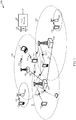
- the wireless communications system 100 includes base stations (or cells) 105, user equipments (UEs) 115, and a core network 130.
- the base stations 105 may communicate with the UEs 115 under the control of a base station controller, which may be part of the core network 130 or the base stations 105 in various examples.
- Base stations 105 may communicate control information or user data with the core network 130 through backhaul 132.
- the base stations 105 may communicate, either directly or indirectly, with each other over backhaul links 134, which may be wired or wireless communication links.
- the wireless communications system 100 may support operation on multiple carriers (waveform signals of different frequencies).
- Multi-carrier transmitters may transmit modulated signals simultaneously on the multiple carriers.
- each communication link 125, between a base station 105 and UE 115, or communication link 126, between two UEs 115 may be a multi-carrier signal modulated according to the various radio technologies described above.
- Each modulated signal may be sent on a different carrier and may carry control information (e.g., reference signals, control channels, etc.), overhead information, data, etc.
- the base stations 105 may wirelessly communicate with the UEs 115 via one or more base station antennas. Each of the base station 105 sites may provide communication coverage for a respective coverage area 110.
- a base station 105 may be referred to as a base transceiver station, a radio base station, an access point, a radio transceiver, a basic service set (BSS), an extended service set (ESS), a NodeB, an evolved NodeB (eNodeB or eNB), a Home NodeB, a Home eNodeB, or some other suitable terminology.
- the coverage area 110 for a base station may be divided into sectors making up only a portion of the coverage area.
- the wireless communications system 100 may include base stations 105 of different types (e.g., macro, micro, or pico base stations). There may be overlapping coverage areas for different technologies.
- the wireless communications system 100 may be an LTE/LTE-A network, wide area network (WAN), etc.
- LTE/LTE-A networks the terms evolved Node B (eNB) may be generally used to describe the base stations 105.
- the wireless communications system 100 may be a Heterogeneous LTE/LTE-A network in which different types of eNBs provide coverage for various geographical regions.
- each eNB 105 may provide communication coverage for a macro cell, a pico cell, a femto cell, or other types of cell.
- a macro cell generally covers a relatively large geographic area (e.g., several kilometers in radius) and may allow unrestricted access by UEs with service subscriptions with the network provider.
- a pico cell may generally cover a relatively smaller geographic area and may allow unrestricted access by UEs with service subscriptions with the network provider.
- a femto cell may also generally cover a relatively small geographic area (e.g., a home) and, in addition to unrestricted access, may also provide restricted access by UEs having an association with the femto cell (e.g., UEs in a closed subscriber group (CSG), UEs for users in the home, and the like).
- An eNB for a macro cell may be referred to as a macro eNB.
- An eNB for a pico cell may be referred to as a pico eNB.
- an eNB for a femto cell may be referred to as a femto eNB or a home eNB.
- An eNB may support one or multiple ( e.g., two, three, four, and the like) cells.
- the core network 130 may communicate with the eNBs 105 via a backhaul 132 (e.g., S1, etc.).
- the eNBs 105 may also communicate with one another (e.g., directly or indirectly) via backhaul links 134 (e.g., X2, etc.) or via backhaul 132 (e.g., through core network 130).
- the wireless communications system 100 may support synchronous or asynchronous operation. For synchronous operation, the eNBs may have similar frame timing, and transmissions from different eNBs may be approximately aligned in time. For asynchronous operation, the eNBs may have different frame timing, and transmissions from different eNBs may not be aligned in time.
- the techniques described herein may be used for either synchronous or asynchronous operations.
- the UEs 115 may be dispersed throughout the wireless communications system 100, and each UE may be stationary or mobile.
- a UE 115 may also be referred to by those skilled in the art as a mobile station, a subscriber station, a mobile unit, a subscriber unit, a wireless unit, a remote unit, a mobile device, a wireless device, a wireless communications device, a remote device, a mobile subscriber station, an access terminal, a mobile terminal, a wireless terminal, a remote terminal, a handset, a user agent, a mobile client, a client, or some other suitable terminology.
- a UE 115 may be a cellular phone, a personal digital assistant (PDA), a wireless modem, a wireless communication device, a handheld device, a tablet computer, a laptop computer, a cordless phone, a wireless local loop (WLL) station, or the like.
- PDA personal digital assistant
- a UE may be able to communicate with macro eNBs, pico eNBs, femto eNBs, relays, and the like.
- a UE 115 may operate within the coverage areas 110 of more than one base station 105.
- a UE 115 may also operate within the coverage area 110 of a single base station 105. In either case, various UEs 115 may be within close enough proximity to communicate directly via D2D communications.
- the communication links 125 shown in wireless communications system 100 may include uplink (UL) transmissions from a UE 115 to a base station 105, or downlink (DL) transmissions, from a base station 105 to a UE 115.
- the downlink transmissions may also be called forward link transmissions while the uplink transmissions may also be called reverse link transmissions.
- communication links 126 may support device to device (D2D) communications between UEs 115.
- D2D device to device
- interference may occur between D2D communications over link(s) 126 and uplink communications over link(s) 125.
- wireless communications system 100 which may also be called a WAN, or base station 105 of WAN 100 may implement a WAN frequency hopping scheme for communications over links 125, particularly for retransmissions according to a HARQ process.
- the WAN frequency hopping scheme may conflict with D2D communications between two UEs 115 over links 126, thus causing interference and degrading communication performance (e.g., throughput, error correction, etc.).
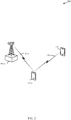
- the wireless communications system 200 which may be an example of wireless communications system 100 described in reference to FIG. 1 , includes two D2D enabled UEs 115-a and 115-b and a base station 105-a.
- D2D UE 105-a may communicate with base station 105-a over link 125-a and with UE 115-b over link 126-a.
- UEs 115-a and 115-b or base station 105-a may be examples of UEs 115 or base stations 105 described in reference to FIG. 1 .
- base station 105-a may implement a frequency hopping scheme or sequence for communications across link 125-a with UE 115-a.
- the frequency hopping scheme may be a type 1 hopping scheme (fixed frequency offset for transmissions) or a type 2 hopping scheme (cell specific hopping and mirroring), or other types of hopping schemes.
- type 1 WAN frequency hopping may provide for hopping with limited resource options
- type 2 WAN frequency hopping may provide for better diversity due to sub-band hopping and mirroring operations.
- Type 2 hopping may provide for better inter-cell interference management.
- both type 1 and type 2 are limited by resource allocation constraints, as both are limited by the size of resource allocation field in DCI format 0. Additionally, the maximum number of RBs for a single user for type 2 hopping is further limited by the size of a sub-band.
- the retransmissions of UE 115-a may assume synchronous operation (e.g., fixed timing across a cell served by base station 105) with automatic scheduling of retransmissions every fixed number of sub frames (e.g., 8 sub frames).
- the frequency hopping scheme may be applied to uplink communications from the UE 115-a over links 125-a, such as for HARQ retransmissions when a first transmission over link 125-a fails (e.g., when an acknowledgment (ACK) message is not received by the UE 115-a).
- HARQ retransmissions by the UE 115-a may occur at set intervals after the first (original) transmission is sent. For example, in FDD systems, the interval may be every 8th subframe.
- the UE 115-a may concurrently communicate with base station 105-a over link 125-a and UE 115-b over link 126-a.
- the UE 115-a may communicate with UE 115-b over link 126-a via D2D communication protocols, which may be different than WAN communication protocols used by the UE 115-a to communicate with base station 105-a over link 125-a.
- D2D frequency hopping schemes for retransmissions may be random or pseudo random. This may result in interference between WAN HARQ retransmissions over link 125-a and D2D retransmissions over link 126-a.
- the base station 105-a may coordinate a D2D frequency hopping scheme with a WAN frequency hopping scheme.
- the base station 105-a may communicate the D2D frequency hopping scheme to the UE 115-a via control signaling over link 125-a ( e.g., using the PDCCH).
- the UE 115-a may communicate with UE 115-b over link 126-a without causing unavoidable interference with WAN communications, and particularly uplink HARQ transmissions from UE 115-a and other UEs 115 (not shown) communicating with base station 105-a.
- FIGs. 3A and 3B block diagrams illustrates communication resources 300-a and 300-b including one subframe 305 divided into resource blocks that may be used by a UE 115 for communicating with one or more UEs 115 or base stations 105 on the uplink, as described in reference to FIGs. 1 or 2 .
- Each subframe 305 may be approximately 1 millisecond (ms) in duration, and 10 subframes may make up a radio frame.
- Each subframe 305 may include two slots, 310, 315. Each radio frame may thus include 20 slots.
- LTE utilizes orthogonal frequency division multiplexing (OFDM) on the downlink and single-carrier frequency division multiplexing (SC-FDM) on the uplink.
- OFDM and SC-FDM partition the system bandwidth into multiple orthogonal subcarriers, which are also commonly referred to as tones, bins, etc.
- Each subcarrier may be modulated with data.
- modulation symbols are sent in the frequency domain with OFDM and in the time domain with SC-FDM.
- the spacing between adjacent subcarriers may be fixed, and the total number of subcarriers may be dependent on the system bandwidth. For example, the number of subcarriers may be equal to 128, 256, 512, 1 024 or 2048 for system bandwidth of 1.25, 2.5, 5, 10 or 20 MHz, respectively.
- Resource blocks 320-a, 320-b may be defined in each slot 310, 315.
- Each resource block may cover multiple subcarriers (e.g., 12 subcarriers) in one slot 310, 315.
- the number of resource blocks in each slot may be dependent on the system bandwidth and may range from 6 to 110.
- the resource blocks may also be referred to as physical resource blocks (PRBs). Multiple subbands (not show) including one or more PRBs may also be defined, where the number of subbands may be dependent on the system bandwidth.
- a frequency hopping pattern may be repeated across subframes in a radio frame for the same resource index.
- the hopping pattern may be carried out over the Physical Uplink Control Channel (PUCCH), and may include multiple PUCCH formats, such as 1/1a/1b, 2/2a/2b, 3, etc.
- PUCCH Physical Uplink Control Channel
- multiplexing may be performed by applying different cyclic time shifts to formats 1/1a/1b and 2/2a/2b. For example, with 12 shifts, N cs 1 ⁇ 0,1 , ... , 7 are assigned to format 1/1a/1b, resulting in N cs 1 / ⁇ shift PUCCH possible shifts, where ⁇ shift PUCCH ⁇ 1 2,3 . In some cases, both parameters may be provided by higher layers.
- a parameter c representing a number of time domain orthogonal spreading codes for multiplexing (also corresponding to the number of reference symbols per slot) may be chosen resulting in a total of cN cs 1 / ⁇ shift PUCCH possible resource indices for format 1/1a/1b.
- n PUCCH 1 p ⁇ may be determined for semi-persistent scheduled downlink data transmissions over the Physical Downlink Shared Channel (PDSCH) by a higher layer.
- PDSCH Physical Downlink Shared Channel
- n PUCCH 1 p ⁇ may be determined implicitly based on the index of the first CCE of the PDCCH message.
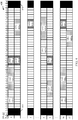
- a block diagram illustrates uplink communication resources 400 divided into 0 through 49 resource blocks (RBs) 405 and multiple subframes represented by index i 410.
- Resources 400 may be examples of one or more aspects of resources 300-a or 300-b described in reference to FIGs. 3A or 3B .
- Resources 400 may be used for uplink communications, such as over links 125, 126 by a UE 115 ( e.g., UE 115-a of FIG. 2 ), with base station(s) 105 ( e.g., base station 105-a of FIG. 2 ), or communications with UE(s) 115 (e.g., UE 115-b of FIG. 2 ), as described above in reference to FIGs. 1 or 2 .
- resources 415 and 420 may be reserved for communication over the PUCCH, such as for control information, etc.; however, it should appreciated that other RBs 405 may be reserved or utilized for the PUCCH.
- RBs 0-49 may represent one subband, with RBs 3-46 representing PUSCH resources.
- any other number of RBs 405 are contemplated herein, and the RBs 405 may be divided into any number of subbands.
- resources 400 are utilized by three UEs 115 and a D2D UE.
- UE1 may assigned to transmit on the uplink at resources 425, UE2 at 430, and UE3 at 435.
- D2D UE transmissions may be scheduled on resources 440.
- a serving base station 105 may assign particular resources to each of UE1 through UE3 and may define a WAN frequency hopping pattern for such transmissions (e.g. for uplink transmissions to the base station 105).
- a transmission from any of UEs 1-3 may fail such that the same information (e.g., packet, code block, etc.) may need to be retransmitted.
- retransmission may be scheduled according to a HARQ process, such that retransmissions occur at a given interval of subframes after the first failed transmission (e.g., when no ACK is received). For example, in FDD systems, the interval may be set at 8 subframes.
- Base station 105 may instruct UEs 1-3 to utilize a fixed frequency offset for every other retransmission for HARQ, to improve transmission diversity and reduce interference. This may correspond to type 1 hopping.
- the first time slot (which may represent a subframe 410 as shown in FIG. 4 or a slot, such as 310, 315 of FIGs.
- UE1 may transmit on RBs 5-7 in subframe 0 at 425-a. After determining that transmission 425-a was not properly received, UE1 may then be instructed to retransmit at RBs 26-29 in subframe 8 at 425-b. This retransmission may be according to a fixed offset of 22 RBs; however, it should be appreciated that other frequency offsets may be utilized. If the retransmission fails again, UE1 may be instructed to retransmit over RBs 4-7 in subframe 16 at 425-c, and so forth.
- UEs 2 and 3 may be instructed to follow the same retransmission hopping pattern (e.g., 22 RB offset for every other transmission), but starting at different RBs (e.g., UE2 at RBs 11-20 in subframe 0 at 430-a and UE3 at RBs 35-41 in subframe 1 at 435-a).
- retransmission hopping pattern e.g., 22 RB offset for every other transmission
- different RBs e.g., UE2 at RBs 11-20 in subframe 0 at 430-a and UE3 at RBs 35-41 in subframe 1 at 435-a.
- the base station 105 may instruct the D2D UE to apply a first offset on even numbered subframes after the first transmission 440-a and apply a second offset on odd numbered subframes after the first transmissions 440-a.
- the second offset may be set to zero RBs. Because D2D retransmission schemes are generally not synchronized as HARQ retransmission schemes, D2D retransmissions may occur on a more random basis such that retransmissions may occur at any number of subframes after a first transmission 440-a.
- a base station 105 may determine the D2D frequency hopping scheme and communicate the scheme to the D2D UE. In this way, interference/conflicts on RBs may be reduced between WAN HARQ retransmissions 425, 430, or 435, and D2D retransmissions 440.
- the D2D UE may first transmit to another D2D UE at 440-a including RBs 22-25 at subframe 0.
- the D2D UE may be instructed to retransmit 440-b in subframe 1 at the zero offset (e.g., at RBs 22-25).
- the D2D UE may then be instructed, according to the D2D frequency hopping pattern, to retransmit at 440-c in subframe 4 (even subframe) at RBs 38-41 (e.g., a 16 RB offset), at 440-d at RBs 22-25 in subframe 9 (e.g., a 0 RB offset), and at 440-e at RBs 38-41 in subframe 16 (e.g., a 16 RB offset).
- a D2D retransmission frequency hopping scheme may be coordinated by the base station 105 to avoid or minimize collisions with other uplink transmissions of UEs 115 communicating via the WAN.
- D2D retransmissions may vary for each retransmission.
- other numbers of subframe intervals may be implemented between D2D retransmissions, according to different schemes, patterns, etc.
- the D2D frequency hopping scheme may be determined based on congestion in the served network, number of UEs 115 communicating on the uplink, previously collected or determined interference metrics, etc.
- Inter-subframe hopping is shown in FIG. 4 . However, it should be appreciated that intra-subframe hopping may be implemented in a similar manner, with every subframe split into two slots 310, 315.
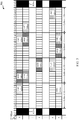
- a block diagram illustrates uplink communication resources 500 divided into 0 through 49 resource blocks (RBs) 405-a and multiple sub frames represented by index i 410-a.
- Resources 500 may be examples of one or more aspects of resources 300-a, 300-b, or 400 described in reference to FIGs. 3A, 3B , or 4 .
- Resources 500 may be used by a UE 115 (e.g., UE 115-a of FIG. 2 ) for uplink communications over links 125 with base station(s) 105, and D2D communications over link 126 with other D2D UE(s) 115, as described above in reference to FIGs. 1 or 2 .
- resources 415-a and 420-a may be reserved for communication over the PUCCH, such as for control information, etc.
- RBs 3-46 e.g., PUSCH resources
- resources 500 are utilized by four UEs 115 and a D2D UE.
- UE1 may assigned to transmit on the uplink at resources 525, UE2 at 530, UE3 at 535, and UE4 at 545.
- D2D UE transmissions may be scheduled on resources 540.
- a serving base station 105 may assign particular resources to each of UE1 through UE4 and may define a WAN frequency hopping pattern for such transmissions (e.g., for uplink transmissions to the base station 105).
- a transmission from any of UEs 1-4 may fail, such that the same information (e.g., packet, code block, etc.) may need to be retransmitted.
- retransmission may be scheduled according to a HARQ process, such that retransmissions occur at a given interval of subframes after the first failed transmission (e.g., 8 subframes).
- Base station 105 may instruct UEs 1-4 to utilize a type 2 frequency hopping scheme for HARQ retransmissions, for example to improve transmission diversity and reduce interference.
- Type 2 hopping may include cell-specific hopping and mirroring.
- UE1 may transmit on resources 525-a (RBs 9-13) in subframe 0 in subband 505. After determining that transmission 525-a was not properly received, UE1 may then retransmit, according to a WAN frequency hopping scheme, at 525-b (RBs 42-46) in subframe 8 in subband 520. This retransmission may represent a subband hop of 3 subbands and no mirroring (transmissions 525-b is at the end of subband 520 as transmission 525-a was also at the end of subband 505). Similarly, UE3 may be instructed to transmit on resources 535-a (RBs 30-35) in subframe 0 in subband 515.
- resources 535-a RBs 30-35
- UE3 may, according to a WAN frequency hopping pattern, retransmit at resources 535-b (RBs 20-24) in subframe 8 in subband 510. This retransmission may represent a subband hop of 1 subband and no mirroring.
- UE2 may first transmit at 530-a (RBs 36-40) in subframe 1 in subband 520. After a failed transmission, UE2 may retransmit at 530-b (RBs 30-35) in subframe 9 in subband 515.
- UE4 may first transmit at 545-a (RBs 14-19) in subframe 1 in subband 510, and after a failed transmission, may retransmit at 545-b (RBs 8-13) in subframe 9 in subband 505.
- the retransmissions of one or more of UEs 1-4 may continue according to any of a variety of hopping schemes.
- a simple offset based on the number of subframes may be less effective (e.g., the example described in reference to FIG. 4 ).
- the base station 105 may associate a cell identification (ID) of the base station 105 with a D2D frequency hopping scheme.
- the D2D frequency hopping scheme may be coordinated with the type 2 WAN frequency hopping scheme.
- coordinating may include seeding the D2D frequency hopping pattern with the same seed used for the type 2 WAN frequency hopping scheme (e.g., based on the equations as described above, with the same seed in a random number generator, etc.).
- coordinating may include predictively avoiding resources utilized by the WAN frequency hopping scheme.
- the base station 105 may associate D2D-specific resources with a D2D frequency hopping scheme. For instance, the D2D frequency hopping scheme may be specific to the resources reserved for D2D communications.
- the WAN frequency hopping scheme and the D2D frequency hopping scheme may have the same logical RB to physical RB mapping sequence.
- the base station 105 may know which logical RBs are occupied by the WAN UEs 1-4 due to the nature of synchronous HARQ implemented on the uplink. In this case, the base station 105 may easily allocate D2D resources to avoid collisions.
- the base station 105 may determine the D2D frequency hopping scheme.
- the D2D UE 115 may receive information of the WAN frequency hopping scheme, and determine at least part of the D2D frequency hopping scheme/determine when to transmit one or more messages to another D2D UE 115 based on the WAN frequency hopping information.
- the D2D UE may first transmit to another D2D UE at 540-a (RBs 14-19) in subframe 0 in subband 510.
- the D2D UE may be instructed to retransmit at 540-b (RBs 30-35) in subframe 1 in subband 515.
- the D2D UE may then be instructed, according to the D2D frequency hopping pattern, to retransmit at 540-c (RBs 20-24 in subframe 4 in subband 510), and at 540-d (RBs 25-30 in subframe 9 in subband 515), and so on.
- a D2D retransmission frequency hopping scheme may be coordinated by the base station 105 to avoid or minimize collisions with other uplink transmissions of UEs 115 communicating via the WAN.
- the base station 105 may transmit a D2D scheduling grant according to the D2D frequency hopping scheme via the PDCCH to the D2D enabled UE 115.
- the scheduling grant may include instructions instructing the D2D enabled UE to transmit the cell ID to a second D2D enabled UE, wherein the second D2D enabled UE is not associated with the cell ID ( i.e . , is associated with another cell). In this way, inter-cell interference may be mitigated by coordinating inter-cell D2D retransmissions.
- the scheduling grant may specify a first resource for the D2D UE 115 to transmit a scheduling assignment to an inter-cell D2D UE 115.
- the first resource used to transmit the scheduling assignment may implicitly indicate the cell ID.
- the base station 105 may establish rules for determining/indicating which resources are associated with different neighboring cell IDs, and thus what D2D frequency hopping scheme is applicable.
- the inter-cell D2D UE 115 may determine which cell ID (and hence what D2D frequency scheme) is to be utilized for communications with the sending D2D UE 115.
- the base station 105 may determine a D2D frequency scheme based on the resources specifically reserved for D2D communications. In such an instance, the base station 105 may send an indication of the D2D-specific resources and the associated frequency hopping scheme to the D2D UE 115.
- Inter-subframe hopping is shown in FIG. 5 . However, it should be appreciated that intra-subframe hopping may be implemented in a similar manner, with every subframe split into two slots 310, 315.
- a block diagram illustrates uplink communication resources 600 divided into 0 through 49 resource blocks (RBs) 405-b and multiple subframes represented by index i 410-b.
- Resources 600 may be examples of one or more aspects of resources 300-a, 300-b, 400, or 500 described in reference to FIGs. 3A, 3B , 4 , or 5 .
- Resources 600 may be used by a UE 115 (e.g., UE 115-a of FIG. 2 ) for uplink communications over links 125 with base station(s) 105, and D2D communications over link 126 with other D2D UE(s) 115, as described above in reference to FIGs. 1 or 2 .
- resources 415-b and 420-b may be reserved for communication over the PUCCH, such as for control information, etc.
- RBs 3-46 e.g., PUSCH resources
- resources 600 are utilized by four UEs 115 and a D2D UE.
- UE1 may assigned to transmit on the uplink at resources 525, UE2 at 530, UE3 at 535, and UE4 at 545.
- D2D UE transmissions may be scheduled on resources 540.
- the frequency hopping for uplink transmissions for UEs 1-4 may follow a type 2 hopping pattern as described above in reference to FIG. 5 . Accordingly, the frequency hopping of UEs 1-4 will not be repeated here for the sake of brevity.
- coordination of a D2D frequency hopping scheme with a type 2 WAN frequency hopping scheme may include partitioning off a portion or subset of PUSCH resources (e.g., RBs 3-7 and 42-46 as illustrated) for D2D communications only.
- the base station 105 may set one or more thresholds to indicate to the D2D UE 115 and UEs 1-4 which resources are to be utilized by the D2D UE 115.
- the threshold may include one or more high resource block thresholds, such as 605, 610, or one or more low resource block thresholds 615, 620.
- the D2D UE may transmit/retransmit between thresholds 605 and 610 in subframe 0, and between thresholds 610 and 620 in subframes 1, 4, and 9.
- intra-cell and inter-cell interference may be reduced or eliminated with minimum overhead (e.g., only the four thresholds may be needed to implement this D2D frequency hopping scheme).
- a default cell ID may be used at least in part to indicate the D2D frequency hopping scheme (e.g., a value of 510).
- the D2D frequency hopping scheme may be communicated by the base station 105 to the D2D UE 115 via a scheduling grant.
- the scheduling grant may be in the form of a system information block (SIB) and may include one or more of the following parameters:
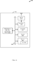
- FIG. 7 shows a block diagram 700 of a base station 105-b configured for coordinating a D2D frequency hopping scheme with a WAN frequency hopping scheme, in accordance with various examples described herein.
- the base station 105-b may be an example of at least one aspect of base stations 105 described above with reference to FIGs. 1 or 2 .
- the base station 105-b may communicate with at least one UE 115 via communication link 125, as described above in reference to FIGs. 1 or 2 or via the coordination techniques described in reference to FIGs. 4 , 5 , or 6 .
- the base station 105-b may include a receiver module 705, a WAN frequency hopping module 710, a D2D frequency hopping coordination module 715, and a transmitter module 735.
- the D2D frequency hopping coordination module 715 may include one or more of a D2D offset module 720, an inter-cell scheduling grant module 725, or a D2D resource determination module 730. Each of these components may be in communication with each other.
- the components of the base stations 105 may, individually or collectively, be implemented using at least one application-specific integrated circuit (ASICs) adapted to perform some or all of the applicable functions in hardware.
- ASICs application-specific integrated circuit
- the functions may be performed by at least one other processing unit (or core), on at least one integrated circuit.
- other types of integrated circuits e.g., Structured/Platform ASICs, Field Programmable Gate Arrays (FPGAs), and other Semi-Custom ICs), which may be programmed in any manner known in the art.
- the functions of each unit may also be implemented, in whole or in part, with instructions embodied in a memory, formatted to be executed by at least one general or application-specific processor.
- the receiver module 705 may receive information such as packet, data, or signaling information regarding what the base station 105-b has received or transmitted. The received information may be utilized by the base station 105-b for a variety of purposes. In some cases, the receiver module 705 may be configured to receive data or transmissions, for example from at least one UE 115, to further enable the various techniques described above for coordinating a D2D retransmission frequency hopping scheme with a WAN frequency hopping scheme for D2D enabled UEs 115.
- the transmitter module 735 may transmit information such as packet, data, or signaling information from the base stations 105-b. In some cases, the transmitter module 735 may be configured to transmit data to one or more UEs 115, such as to coordinate D2D communications or retransmissions.
- the WAN frequency hopping module 710 may identify a WAN frequency hopping scheme utilized in the WAN served by the base station 105-b. In some cases, the WAN frequency hopping module 710 may configure the WAN frequency hopping scheme, and in other cases the hopping scheme may be accessed from another network device via a request transmitted by the transmitter module 735. The WAN frequency hopping module 710 may communicate the WAN hopping scheme to the D2D frequency hopping coordination module 715.
- the D2D frequency hopping coordination module 715 may utilize the WAN frequency hopping scheme to coordinate a D2D frequency hopping scheme, to be utilized for D2D retransmissions, that may interfere with uplink communications in the WAN.
- the D2D frequency hopping scheme may be coordinated to minimize interference with the WAN frequency hopping scheme.
- the D2D frequency hopping coordination module 715 may then communicate the D2D frequency hopping scheme to the transmitter module 735 to be transmitted to a D2D enabled UE 115, to implement the frequency hopping scheme.
- the D2D frequency hopping coordination module 715 may include a D2D offset module 720. If the WAN frequency hopping module 710 determines that the WAN frequency hopping scheme is type 1, the D2D offset module 720 may then be instructed to determine a first or second offset for D2D retransmissions. The D2D offset module 720 may determine a first offset for transmissions transmitted an even number of subframes after a first transmission or a second offset for transmissions transmitted an odd number of subframes after a first transmission. In some instances, the first or second offsets may be set to zero. The D2D offset module 720 may then communicate the first or second offsets to the transmitter module 735 to be transmitted to a D2D enabled UE 115, for example over the PDCCH.
- the D2D frequency hopping coordination module 715 may include an inter-cell scheduling grant module 725 and a D2D resource determination module 730. If the WAN frequency hopping module 710 determines that the WAN frequency hopping scheme is type 2, the inter-cell scheduling grant module 725 may then be instructed to configure a scheduling grant to be communicated via transmitter module 735 to a D2D enabled UE 115.
- the scheduling grant may include an indication of resources reserved for D2D communications. Accordingly, the scheduling grant may include a D2D frequency hopping scheme associated with the D2D-specific resources. In some cases, the scheduling grant may include an indication of the D2D frequency hopping scheme associated with a cell ID of the base station 105-b.
- the scheduling grant may further include instructions instructing the D2D enabled UE 115 to transmit the cell ID to a second D2D enabled UE 115, where the second D2D enabled UE 115 is not associated with the cell ID (e.g., an inter-cell UE 115).
- D2D inter-cell communications may be coordinated with the WAN frequency hopping scheme.
- the D2D resource determination module 730 may determine a subset of available PUSCH resources to be reserved for D2D communications (e.g., retransmissions). This may include determining a low resource block threshold, a high resource block threshold, or both. The D2D resource determination module may then communicate the one or more thresholds to the transmitter module 735 to be transmitted to the D2D enabled UE 115 to similarly reduce interference between WAN uplink retransmissions and D2D retransmissions.
- FIG. 8 shows a block diagram 800 of a UE 115-c configured for retransmitting one or more messages to a D2D enabled UE 115 according to a D2D frequency hopping scheme communicated by a base station 105, in accordance with various examples described herein.
- the UE 115-c may be an example of at least one aspect of UEs 115 described above with reference to FIGs. 1 , or 2 .
- the UE 115-c may communicate with at least one base station 105 via communication link 125 or at least one UE 115 via link 126 as described above in reference to FIGs. 1 or 2 or via the coordination techniques described in reference to FIGs. 4 , 5 , or 6 .
- the UE 115-c may include a receiver module 805, a D2D frequency hopping determination module 810, which may further include an offset determination module 815, and a transmitter module 820. Each of these components may be in communication with each other.
- the components of the UE 115-c may, individually or collectively, be implemented using at least one application-specific integrated circuit (ASICs) adapted to perform some or all of the applicable functions in hardware.
- ASICs application-specific integrated circuit
- the functions may be performed by at least one other processing unit (or core), on at least one integrated circuit.
- other types of integrated circuits e.g., Structured/Platform ASICs, Field Programmable Gate Arrays (FPGAs), and other Semi-Custom ICs), which may be programmed in any manner known in the art.
- the functions of each unit may also be implemented, in whole or in part, with instructions embodied in a memory, formatted to be executed by at least one general or application-specific processor.
- the receiver module 805 may receive information such as packet, data, or signaling information regarding what the UE 115-c has received or transmitted. The received information may be utilized by the UE 115-c for a variety of purposes. In some cases, the receiver module 805 may be configured to receive data or transmissions, for example from a base station 105, to further enable the various techniques described above for communicating with a D2D enabled UE 115 according to a base station determined D2D frequency hopping scheme.
- the transmitter module 820 may transmit information such as packet, data, or signaling information from the UE 115-c. In some cases, the transmitter module 820 may be configured to transmit data on the uplink to a one or more base stations 105 via links 125 or transmit one or more D2D messages to a D2D enabled UE 115 via links 126 described in reference to FIGs. 1 or 2 .
- the receiver module 805 may receive a D2D frequency hopping scheme from a base station 105 associated with a WAN with a coverage are corresponding to a location of the UE 115-c.
- the D2D frequency hopping scheme may be coordinated with a WAN frequency hopping scheme, for example by the base station 105.
- the receiver module 805 may communicate this information to the D2D frequency hopping determination module 810, which may identify the communicated D2D frequency hopping scheme.
- the offset determination module 815 of the D2D frequency hopping determination module 810 may identify/determine one or more offsets (e.g., in the WAN type 1 hopping scheme example), for retransmitting one or more messages to another D2D enabled UE 115.
- a first offset may correspond to transmissions transmitted on even subframes after a first transmission
- a second offset may correspond to transmissions transmitted on odd subframes after the first transmission.
- the D2D frequency hopping determination module 810 may determine resources reserved for D2D communications. In such a case, the D2D frequency hopping determination module 810 may determine a D2D frequency hopping scheme based on the D2D-specific resources. In this or other instances, the D2D frequency hopping determination module 810 may determine resources for transmissions/retransmissions to another D2D enabled UE 115 based on information received from the base station 105. In some cases, this may include identifying one or more thresholds for D2D allocated resources. The D2D frequency hopping determination module 810 may then instruct the transmitter module 820 to transmit/retransmit to the D2D UE 115 on the allocated resources.
- the D2D frequency hopping determination module 810 may determine a cell ID associated with the base station 105 or the WAN frequency hopping scheme implemented by the base station 105.
- the UE 115-c may then instruct the transmitter module 820 to communicate the cell ID to the inter-cell D2D enabled UE 115 to instruct the inter-cell D2D enabled UE 115 to avoid retransmitting on resources utilized by the WAN hopping scheme, etc., as described above.
- FIG. 9 shows a block diagram 900 of a base station 105-c configured for coordinating a D2D frequency hopping scheme with a WAN frequency hopping scheme for a D2D enabled UE 115, in accordance with various examples described herein.
- the base station 105-b may be an example of at least one aspect of base stations 105 described above with reference to FIGs. 1 , 2 or 7 or may implement at least one aspect of the WAN frequency hopping module 710 or the D2D frequency hopping coordination module 715 described above with reference to FIG. 7 .
- the base stations 105-c may communicate with at least one UE 115 via communication link 125, as described above in reference to FIGs. 1 or 2 or via the coordination techniques described in reference to FIGs. 4 , 5 , or 6 .
- the components of the base station 105-c may, individually or collectively, be implemented using at least one application-specific integrated circuit (ASIC) adapted to perform some or all of the applicable functions in hardware.
- ASIC application-specific integrated circuit
- the functions may be performed by at least one other processing unit (or core), on at least one integrated circuit.
- other types of integrated circuits may be used (e.g., Structured/Platform ASICs, Field Programmable Gate Arrays (FPGAs), and other Semi-Custom ICs), which may be programmed in any manner known in the art.
- the functions of each unit may also be implemented, in whole or in part, with instructions embodied in a memory, formatted to be executed by at least one general or application-specific processor.
- the base station 105-c includes antenna(s) 915, transceiver(s) 920, memory 935, a processor 930, and I/O devices 925, which each may be in communication, directly or indirectly, with each other, for example, via at least one bus 945.
- the transceiver(s) 920 may be configured to communicate bi-directionally, via the antennas 915 with at least one wired or wireless link, such as any of communication links 125 or 126 described above in reference to FIGs. 1 , or 2 .
- the transceiver(s) 920 may include a modem configured to modulate the packets and provide the modulated packets to the antennas 915 for transmission, and to demodulate packets received from the antennas 915.
- the transceiver(s) 920 may, in conjunction with the antennas 915, transmit and receive packets.
- the transceiver(s) 920 may be configured to maintain multiple concurrent communication links using the same or different radio interfaces (e.g., Wi-Fi, cellular, etc.).
- the base station 105-c may include a single antenna 915, or the base station 105-c may include multiple antennas 915.
- the base station 105-c may be capable of employing multiple antennas 915 for transmitting and receiving communications in a multiple-input multiple-output (MIMO) communication system.
- MIMO multiple-input multiple-output
- the memory 935 may include random access memory (RAM) and read-only memory (ROM).
- the memory 935 may store computer-readable, computer-executable software 940 containing instructions that are configured to, when executed, cause the processor 930 to perform various functions described herein.
- the software 940 may not be directly executable by the processor 930 but may be configured to cause the computer ( e.g., when compiled and executed) to perform functions described herein.
- the processor 930 may include an intelligent hardware device (e.g., a central processing unit (CPU), a microcontroller, an application specific integrated circuit (ASIC), etc.).
- CPU central processing unit
- ASIC application specific integrated circuit
- the base station 105-c may further include a WAN frequency hopping module 710-a and a D2D frequency hopping coordination module 715-a.
- these components of base station 105-c may be in communication with some or all of the other components of the base station 105-c via bus 945. Additionally or alternatively, functionality of these modules may be implemented via the transceiver 920, as a computer program product stored in software 940, or as at least one controller element of the processor 930.
- the WAN frequency hopping module 710-a and the D2D frequency hopping coordination module 715-a may be implemented as subroutines in memory 935/software 940 executed by the processor 930. In other cases, these modules may be implemented as sub-modules in the processor 930 itself.
- the WAN frequency hopping module 710-a and the D2D frequency hopping coordination module 715-a of base station 105-c may further implement the procedures described above for coordinating a D2D frequency hopping pattern with a WAN frequency hopping pattern for D2D retransmissions of a UE 115, and for the sake of brevity, will not be repeated here.
- FIG. 10 is a block diagram 1000 of a UE 115-d configured for retransmitting one or messages to a D2D enabled UE 115 according to a D2D frequency hopping scheme communicated by a base station 105, in accordance with various examples described herein.
- the UE 115-d may be an example of at least one aspect of UEs 115 described above with reference to FIGs. 1 , 2 , or 8 or may implement at least one aspect of the D2D frequency hopping determination module 810 or the offset determination module 815 described above with reference to FIG. 8 .
- the UE 115-d may communicate with at least one base station 105 via communication link 125 or at least one UE 115 via link 126 as described above in reference to FIGs.
- the UE 115-d may have any of various configurations, such as personal computers (e.g., laptop computers, netbook computers, tablet computers, etc.), smartphones, cellular telephones, PDAs, wearable computing devices, digital video recorders (DVRs), internet appliances, routers, gaming consoles, e-readers, display devices, printers, etc.
- the UE 115-d may have an internal power supply (not shown), such as a small battery, to facilitate mobile operation.
- the components of the UE 115-d may, individually or collectively, be implemented using at least one application-specific integrated circuit (ASIC) adapted to perform some or all of the applicable functions in hardware.
- ASIC application-specific integrated circuit
- the functions may be performed by at least one other processing unit (or core), on at least one integrated circuit.
- other types of integrated circuits e.g., Structured/Platform ASICs, Field Programmable Gate Arrays (FPGAs), and other Semi-Custom ICs), which may be programmed in any manner known in the art.
- the functions of each unit may also be implemented, in whole or in part, with instructions embodied in a memory, formatted to be executed by at least one general or application-specific processor.
- the UE 115-d includes antenna(s) 1015, transceiver(s) 1020, memory 1035, a processor 1030, and I/O devices 1025, which each may be in communication, directly or indirectly, with each other, for example, via at least one bus 1045.
- the transceiver(s) 1020 may be configured to communicate bi-directionally, via the antennas 1015 with at least one wired or wireless link, such as any of communication links 125 or 126 described above in reference to FIGs. 1 , or 2 .
- the transceiver(s) 1020 may include a modem configured to modulate the packets and provide the modulated packets to the antennas 1015 for transmission, and to demodulate packets received from the antennas 1015.
- the transceiver(s) 1020 may, in conjunction with the antennas 1015, transmit and receive packets.
- the transceiver(s) 1020 may be configured to maintain multiple concurrent communication links using the same or different radio interfaces (e.g., Wi-Fi, cellular, etc.).
- the UE 115-d may include a single antenna 1015, or the UE 115-d may include multiple antennas 1015.
- the UE 115-d may be capable of employing multiple antennas 1015 for transmitting and receiving communications in a multiple-input multiple-output (MIMO) communication system.
- MIMO multiple-input multiple-output
- the memory 1035 may include random access memory (RAM) and read-only memory (ROM).
- the memory 1035 may store computer-readable, computer-executable software 1040 containing instructions that are configured to, when executed, cause the processor 1030 to perform various functions described herein.
- the software 1040 may not be directly executable by the processor 1030 but may be configured to cause the computer ( e.g., when compiled and executed) to perform functions described herein.
- the processor 1030 may include an intelligent hardware device (e.g., a central processing unit (CPU), a microcontroller, an application specific integrated circuit (ASIC), etc.).
- CPU central processing unit
- ASIC application specific integrated circuit
- the UE 115-d may further include a D2D frequency hopping determination module 810-a.
- this and other components of UE 115-d may be in communication with some or all of the other components of the UE 115-d via bus 1045.
- functionality of these modules may be implemented via the transceiver 1020, as a computer program product stored in software 1040, or as at least one controller element of the processor 1030.
- the D2D frequency hopping module 810-a, including the offset determination module 815 may be implemented as subroutines in memory 1035/software 1040 executed by the processor 1030. In other cases, these module may be implemented as sub-modules in the processor 1030 itself.
- the D2D frequency hopping determination module 810-a may further implement the procedures described above for communicating ( e.g., via retransmissions) with a D2D enabled UE 115 according to a D2D frequency hopping scheme communicated from a serving base station 105, and for the sake of brevity, will not be repeated here.
- FIG. 11 is a flow chart illustrating one example of a method 1100 for coordinating a D2D frequency hopping scheme for D2D retransmissions with a WAN frequency hopping scheme used for HARQ retransmissions, in accordance with various examples described herein.
- the method 1100 is described below with reference to at least one aspect of one of the base stations 105 described with reference to FIGs. 1 , 2 , 7 , or 9 .
- a device such as one of the base stations 105, may execute at least one set of codes to control the functional elements of the device to perform the functions described below.
- a base station 105 may identify a WAN frequency hopping scheme used in the WAN served by the base station 105.
- the operation(s) at block 1105 may in some cases be performed using the WAN frequency hopping module 710 described with reference to FIGs. 7 or 9 .
- the base station 105 may coordinate a D2D frequency hopping scheme for at least one D2D enabled UE with the identified WAN frequency hopping scheme.
- the operation(s) at block 1110 may in some cases be performed using the D2D frequency hopping module 715 described with reference to FIGs. 7 or 9 .
- the base station 105 may communicate the D2D frequency hopping scheme to the at least one D2D enabled UE.
- the operation(s) at block 1115 may in some cases be performed using the transmitter module 735 described with reference to FIGs. 7 or 9 .
- the method 1100 may provide for coordinating a D2D frequency hopping scheme with a WAN frequency hopping scheme. It should be noted that the method 1100 is just one implementation and that the operations of the method 1100 may be rearranged or otherwise modified such that other implementations are possible.
- FIG. 12 is a flow chart illustrating one example of a method 1200 for communicating with a D2D enabled UE 115 according to a D2D frequency hopping scheme coordinated with a WAN frequency hopping scheme, in accordance with various examples described herein.
- the method 1100 is described below with reference to at least one aspect of one of UEs 115 described with reference to FIGs. 1 , 2 , 8 , or 10 .
- a device such as one of the UEs 115, may execute at least one set of codes to control the functional elements of the device to perform the functions described below.
- a UE 115 may receive a D2D frequency hopping scheme, which is coordinated with a WAN frequency hopping scheme, from a base station 105 associated with the WAN.
- the operation(s) at block 1205 may in some cases be performed using the WAN frequency hopping determination module 810 or the receiver module 805 described with reference to FIGs. 8 or 10 .
- UE 115 may transmit at least one message to a second D2D enabled UE 115 according to the D2D frequency hopping scheme.
- the operation(s) at block 1210 may in some cases be performed using the WAN frequency hopping determination module 810 or the transmitter module 820 described with reference to FIGs. 8 or 10 .
- the method 1200 may provide for communicating with a D2D enabled UE 115 according to a D2D frequency hopping scheme. It should be noted that the method 1200 is just one implementation and that the operations of the method 1200 may be rearranged or otherwise modified such that other implementations are possible.
- a CDMA system may implement a radio technology such as CDMA2000, Universal Terrestrial Radio Access (UTRA), etc.
- CDMA2000 covers IS-2000, IS-95, and IS-856 standards.
- IS-2000 Releases 0 and A are commonly referred to as CDMA2000 IX, IX, etc.
- IS-856 (TIA-856) is commonly referred to as CDMA2000 1xEV-DO, High Rate Packet Data (HRPD), etc.
- UTRA includes Wideband CDMA (WCDMA) and other variants of CDMA.
- a TDMA system may implement a radio technology such as Global System for Mobile Communications (GSM).
- GSM Global System for Mobile Communications
- An OFDMA system may implement a radio technology such as Ultra Mobile Broadband (UMB), Evolved UTRA (E-UTRA), IEEE 802.11 (Wi-Fi), IEEE 802.16 (WiMAX), IEEE 802.20, Flash-OFDM, etc.
- UMB Ultra Mobile Broadband
- E-UTRA Evolved UTRA
- Wi-Fi Wi-Fi
- WiMAX IEEE 802.16
- IEEE 802.20 Flash-OFDM
- UTRA and E-UTRA are part of Universal Mobile Telecommunication System (UMTS).
- 3GPP Long Term Evolution (LTE) and LTE-Advanced (LTE-A) are new releases of UMTS that use E-UTRA.
- UTRA, E-UTRA, UMTS, LTE, LTE-A, and GSM are described in documents from an organization named "3rd Generation Partnership Project" (3GPP).
- CDMA2000 and UMB are described in documents from an organization named "3rd Generation Partnership Project 2" (3GPP2).
- 3GPP2 3rd Generation Partnership Project 2
- the techniques described herein may be used for the systems and radio technologies mentioned above as well as other systems and radio technologies.
- the description above describes an LTE system for purposes of example, and LTE terminology is used in much of the description above, although the techniques are applicable beyond LTE applications.
- Information and signals may be represented using any of a variety of different technologies and techniques.
- data, instructions, commands, information, signals, bits, symbols, and chips that may be referenced throughout the above description may be represented by voltages, currents, electromagnetic waves, magnetic fields or particles, optical fields or particles, or any combination thereof.
- DSP digital signal processor
- ASIC application specific integrated circuit
- FPGA field programmable gate array
- a general-purpose processor may be a microprocessor, but in the alternative, the processor may be any conventional processor, controller, microcontroller, or state machine.
- a processor may also be implemented as a combination of computing devices (e.g., a combination of a DSP and a microprocessor, multiple microprocessors, one or more microprocessors in conjunction with a DSP core, or any other such configuration).
- the functions described herein may be implemented in hardware, software executed by a processor, firmware, or any combination thereof. If implemented in software executed by a processor, the functions may be stored on or transmitted over as one or more instructions or code on a computer-readable medium. Other examples and implementations are within the scope and spirit of the disclosure and appended claims. For example, due to the nature of software, functions described above can be implemented using software executed by a processor, hardware, firmware, hardwiring, or combinations of any of these. Features implementing functions may also be physically located at various positions, including being distributed such that portions of functions are implemented at different physical locations.
- Computer-readable media includes both computer storage media and communication media including any medium that facilitates transfer of a computer program from one place to another.
- a storage medium may be any available medium that can be accessed by a general purpose or special purpose computer.
- computer-readable media can comprise RAM, ROM, EEPROM, CD-ROM or other optical disk storage, magnetic disk storage or other magnetic storage devices, or any other medium that can be used to carry or store desired program code means in the form of instructions or data structures and that can be accessed by a general-purpose or special-purpose computer, or a general-purpose or special-purpose processor.
- any connection is properly termed a computer-readable medium.
- Disk and disc include compact disc (CD), laser disc, optical disc, digital versatile disc (DVD), floppy disk and Blu-ray disc where disks usually reproduce data magnetically, while discs reproduce data optically with lasers. Combinations of the above are also included within the scope of computer-readable media.
Landscapes
- Engineering & Computer Science (AREA)
- Computer Networks & Wireless Communication (AREA)
- Signal Processing (AREA)
- Mobile Radio Communication Systems (AREA)
Claims (10)
- Un procédé de communication sans fil comprenant :l'identification (1105), par une station de base, d'un mécanisme de saut de fréquence de réseau étendu "WAN", où le mécanisme de saut de fréquence WAN comprend un décalage fixe signalé par l'intermédiaire d'un canal de commande en liaison descendante physique "PDCCH" pour une transmission sur deux d'un procédé de demande de répétition automatique hybride "HARQ",la coordination (1110) d'un mécanisme de saut de fréquence de dispositif à dispositif "D2D" pour au moins un équipement d'utilisateur "UE" compatible D2D avec le mécanisme de saut de fréquence WAN identifié, etla communication (1115) du mécanisme de saut de fréquence D2D au au moins un UE compatible D2D, autorisant ainsi le au moins un UE compatible D2D à transmettre au moins un message D2D à un deuxième UE compatible D2D en fonction du mécanisme de saut de fréquence D2D.
- Le procédé selon la Revendication 1, où la coordination du mécanisme de saut de fréquence D2D avec le mécanisme de saut de fréquence WAN comprend :
la configuration du mécanisme de saut de fréquence D2D de façon à réduire un brouillage avec le mécanisme de saut de fréquence WAN. - Le procédé selon la Revendication 1, où la coordination du mécanisme de saut de fréquence D2D avec le mécanisme de saut de fréquence WAN comprend :l'utilisation d'un premier décalage pour des transmissions D2D paires, où chaque transmission D2D paire est transmise un nombre pair de sous-trames après une première transmission D2D, etl'utilisation d'un deuxième décalage pour des transmissions D2D impaires, où chaque transmission D2D impaire est transmise un nombre impair de sous-trames après la première transmission D2D.
- Le procédé selon la Revendication 3, où le deuxième décalage est réglé sur zéro.
- Le procédé selon la Revendication 3, où la communication du mécanisme de saut de fréquence D2D au au moins un UE compatible D2D comprend :
la transmission d'au moins un décalage parmi le premier décalage ou le deuxième décalage, ou les deux, par l'intermédiaire du PDCCH. - Le procédé selon la Revendication 3, où au moins un décalage parmi le décalage fixe ou le premier décalage ou le deuxième décalage, ou une combinaison de ceux-ci comprend un nombre de blocs de ressource.
- Le procédé selon la Revendication 1, où le mécanisme de saut de fréquence WAN s'applique à des transmissions en liaison montante.
- Un procédé de communication sans fil comprenant :la réception (1205), par un équipement d'utilisateur "UE" compatible de dispositif à dispositif "D2D", d'un mécanisme de saut de fréquence D2D à partir d'une station de base associée à un réseau étendu "WAN", où le mécanisme de saut de fréquence D2D est coordonné avec un mécanisme de saut de fréquence WAN, où le mécanisme de saut de fréquence WAN comprend un décalage fixe signalé par l'intermédiaire d'un canal de commande en liaison descendante physique "PDCCH" pour une transmission sur deux d'un procédé de demande de répétition automatique hybride "HARQ", etla transmission (1210) d'au moins un message D2D à un deuxième UE compatible D2D en fonction du mécanisme de saut de fréquence D2D.
- Le procédé selon la Revendication 8, où le mécanisme de saut de fréquence D2D comprend un premier décalage à appliquer pour des transmissions D2D paires, où chaque transmission D2D paire est transmise un nombre pair de sous-trames après une première transmission D2D, et
où le mécanisme de saut de fréquence D2D comprend en outre un deuxième décalage à appliquer pour des transmissions D2D impaires, où chaque transmission D2D impaire est transmise un nombre impair de sous-trames après la première transmission D2D. - Une station de base (105-b) comprenant :un module de saut de fréquence de réseau étendu "WAN" (710) destiné à l'identification d'un mécanisme de saut de fréquence WAN, où le mécanisme de saut de fréquence WAN comprend un décalage fixe signalé par l'intermédiaire d'un canal de commande en liaison descendante physique "PDCCH" pour une transmission sur deux d'un procédé de demande de répétition automatique hybride "HARQ",un module de saut de fréquence de dispositif à dispositif "D2D" (715) destiné à la coordination d'un mécanisme de saut de fréquence D2D pour au moins un équipement d'utilisateur "UE" compatible D2D avec le mécanisme de saut de fréquence WAN identifié, etun émetteur (735) destiné à la communication du mécanisme de saut de fréquence D2D au au moins un UE compatible D2D, autorisant ainsi le au moins un UE compatible D2D à transmettre au moins un message D2D à un deuxième UE compatible D2D en fonction du mécanisme de saut de fréquence D2D.
Applications Claiming Priority (3)
| Application Number | Priority Date | Filing Date | Title |
|---|---|---|---|
| US201462025927P | 2014-07-17 | 2014-07-17 | |
| US14/729,753 US9608690B2 (en) | 2014-07-17 | 2015-06-03 | Type 1 and type 2 hopping for device-to-device communications |
| PCT/US2015/034121 WO2016010644A1 (fr) | 2014-07-17 | 2015-06-04 | Saut de type 1 et de type 2 pour communications de dispositif à dispositif |
Publications (2)
| Publication Number | Publication Date |
|---|---|
| EP3170350A1 EP3170350A1 (fr) | 2017-05-24 |
| EP3170350B1 true EP3170350B1 (fr) | 2020-11-18 |
Family
ID=55075450
Family Applications (1)
| Application Number | Title | Priority Date | Filing Date |
|---|---|---|---|
| EP15730349.6A Active EP3170350B1 (fr) | 2014-07-17 | 2015-06-04 | Saut de type 1 pour communications de dispositif à dispositif |
Country Status (6)
| Country | Link |
|---|---|
| US (1) | US9608690B2 (fr) |
| EP (1) | EP3170350B1 (fr) |
| JP (1) | JP6602838B2 (fr) |
| KR (1) | KR102312765B1 (fr) |
| CN (1) | CN106537945B (fr) |
| WO (1) | WO2016010644A1 (fr) |
Families Citing this family (16)
| Publication number | Priority date | Publication date | Assignee | Title |
|---|---|---|---|---|
| US20170238313A1 (en) * | 2014-08-07 | 2017-08-17 | Huawei Technologies Co., Ltd. | Data transmission method, device, and system |
| CA2953323A1 (fr) | 2014-08-28 | 2016-03-03 | Sony Corporation | Dispositif de commande de communication, procede de commande de communication et programme |
| EP3300286B1 (fr) * | 2015-05-18 | 2023-05-10 | Samsung Electronics Co., Ltd. | Procédé et appareil destinés à une communication en réseau iot cellulaire |
| CN114401075B (zh) | 2015-06-26 | 2024-05-07 | Lg电子株式会社 | 无线通信系统中收发设备对设备通信终端的信号的方法和装置 |
| US9673856B1 (en) * | 2015-11-24 | 2017-06-06 | Cisco Technology, Inc. | Hidden channel hopping sequence based on swapping sequence offsets using allocated swapping schedule |
| US10420134B2 (en) * | 2016-02-02 | 2019-09-17 | Cisco Technology, Inc. | System and method to facilitate subframe scheduling in a split medium access control radio access network environment |
| EP3603223A4 (fr) * | 2017-03-24 | 2021-01-13 | Apple Inc. | Signal de réveil pour communication de type machine et dispositifs de l'internet des objets à bande étroite |
| CN111165045A (zh) * | 2017-11-02 | 2020-05-15 | Oppo广东移动通信有限公司 | 用于配置资源的方法、终端设备和网络设备 |
| US10873389B2 (en) * | 2018-02-16 | 2020-12-22 | Qualcomm Incorporated | Phase tracking reference signal symbol mapping |
| US11265097B2 (en) * | 2019-03-04 | 2022-03-01 | Qualcomm Incorporated | Code division multiplexing group hopping for multi-transmission/reception point |
| DE102019209528A1 (de) * | 2019-06-28 | 2020-12-31 | Fraunhofer-Gesellschaft zur Förderung der angewandten Forschung e.V. | Effiziente signalisierung von sprungmustern in zugewiesenen ressourcen |
| US11563533B2 (en) * | 2019-11-25 | 2023-01-24 | Qualcomm Incorporated | Uplink frequency hopping in unlicensed frequency band |
| CN113677024A (zh) * | 2020-05-15 | 2021-11-19 | 华为技术有限公司 | 资源确定方法及装置 |
| KR102357158B1 (ko) * | 2020-08-27 | 2022-02-08 | (주)쏠리드윈텍 | 무선 통신 시스템에서의 데이터 송수신 방법 및 그 장치 |
| WO2023230631A1 (fr) | 2022-05-27 | 2023-11-30 | Roger Paul Hellens | Nouveaux procédés d'identification et d'utilisation de cadres de lecture ouverts en amont |
| WO2024077110A2 (fr) | 2022-10-05 | 2024-04-11 | Roger Paul Hellens | Fusions de gènes rapporteurs uorf pour sélectionner des changements de séquence dans l'édition de gènes dans des uorf pour réguler des gènes d'ascorbate |
Family Cites Families (13)
| Publication number | Priority date | Publication date | Assignee | Title |
|---|---|---|---|---|
| US20050176371A1 (en) | 2004-02-09 | 2005-08-11 | Arto Palin | Synchronization of time-frequency codes |
| KR101448653B1 (ko) * | 2007-10-01 | 2014-10-15 | 엘지전자 주식회사 | 주파수 호핑 패턴 및 이를 이용한 상향링크 신호 전송 방법 |
| WO2010087449A1 (fr) * | 2009-02-02 | 2010-08-05 | 株式会社 エヌ・ティ・ティ・ドコモ | Appareil de station de base et procédé dans un système de communication mobile |
| EP2401884B1 (fr) * | 2009-02-24 | 2017-07-19 | Nokia Technologies Oy | Saut temporel permettant une limitation du brouillage proche-lointain dans des communications de dispositif à dispositif |
| US8787468B2 (en) * | 2009-06-19 | 2014-07-22 | Motorola Mobility Llc | Method and apparatus for multi-radio coexistence |
| US8504052B2 (en) * | 2010-05-06 | 2013-08-06 | Nokia Corporation | Measurements and fast power adjustments in D2D communications |
| JP5986084B2 (ja) * | 2010-08-13 | 2016-09-06 | インターデイジタル パテント ホールディングス インコーポレイテッド | デバイス内干渉軽減のための方法およびシステム |
| EP2651047B1 (fr) * | 2010-12-07 | 2017-08-30 | LG Electronics Inc. | Procédé et dispositif de communication entre des terminaux dans un système de communication sans fil |
| CN102307353B (zh) * | 2011-08-24 | 2013-10-09 | 北京邮电大学 | 多跳频方式与小区间信息交互结合的干扰协调方法 |
| CN103139921B (zh) * | 2011-11-24 | 2015-07-08 | 华为技术有限公司 | 终端直通的方法、终端直通终端和基站 |
| US9635684B2 (en) * | 2012-04-26 | 2017-04-25 | Electronics And Telecommunications Research Insitute | Device to device communication method using partial device control |
| US9154267B2 (en) * | 2012-07-02 | 2015-10-06 | Intel Corporation | Sounding reference signal (SRS) mechanism for intracell device-to-device (D2D) communication |
| EP3021500B1 (fr) * | 2013-07-12 | 2019-03-20 | LG Electronics Inc. | Procede et appareil pour transmettre des signaux d2d dans de reseaux cellulaires de communication |
-
2015
- 2015-06-03 US US14/729,753 patent/US9608690B2/en active Active
- 2015-06-04 EP EP15730349.6A patent/EP3170350B1/fr active Active
- 2015-06-04 CN CN201580038848.6A patent/CN106537945B/zh active Active
- 2015-06-04 KR KR1020177001224A patent/KR102312765B1/ko active IP Right Grant
- 2015-06-04 WO PCT/US2015/034121 patent/WO2016010644A1/fr active Application Filing
- 2015-06-04 JP JP2017502101A patent/JP6602838B2/ja active Active
Non-Patent Citations (1)
| Title |
|---|
| None * |
Also Published As
| Publication number | Publication date |
|---|---|
| CN106537945A (zh) | 2017-03-22 |
| KR102312765B1 (ko) | 2021-10-13 |
| KR20170032307A (ko) | 2017-03-22 |
| JP6602838B2 (ja) | 2019-11-06 |
| US20160020822A1 (en) | 2016-01-21 |
| EP3170350A1 (fr) | 2017-05-24 |
| US9608690B2 (en) | 2017-03-28 |
| JP2017528034A (ja) | 2017-09-21 |
| CN106537945B (zh) | 2020-04-28 |
| BR112017000557A2 (pt) | 2017-11-07 |
| WO2016010644A1 (fr) | 2016-01-21 |
Similar Documents
| Publication | Publication Date | Title |
|---|---|---|
| EP3170350B1 (fr) | Saut de type 1 pour communications de dispositif à dispositif | |
| US11329788B2 (en) | Transmission of uplink control channels over an unlicensed radio frequency spectrum band | |
| US20200205151A1 (en) | Uplink channel design for slot-based transmission time interval (tti) | |
| CN112564879B (zh) | 新无线系统中的半双工操作 | |
| CN108886452B (zh) | 用于共享射频频谱带中配置上行链路控制信道传输的方法 | |
| US20180041998A1 (en) | Methods, systems and apparatus for defining and using phich resources for carrier aggregation | |
| EP3448108B1 (fr) | Procédé et appareil de transmission d'informations de commande de liaison montante | |
| EP3408962B1 (fr) | Conceptions de canaux descripteurs pour canaux de liaison montante dans une bande de spectre de fréquences radio partagées | |
| EP2918033B1 (fr) | Procede et appareil pour faire fonctionner l'agrégation de porteusesdes de cellules tdd | |
| CN108781155B (zh) | 用于在扩展上行链路导频时隙中进行通信的技术 | |
| EP2385650A2 (fr) | Procédé de gestion de transmission de canal de contrôle de liaison montante physique et dispositif de communication associé | |
| EP3427533B1 (fr) | Techniques pour accuser réception de transmissions de demande d'ordonnancement sur un canal partagé de liaison montante physique basé sur la concurrence | |
| BR112017000557B1 (pt) | Salto tipo 1 e tipo 2 para comunicações dispositivo a dispositivo |
Legal Events
| Date | Code | Title | Description |
|---|---|---|---|
| STAA | Information on the status of an ep patent application or granted ep patent |
Free format text: STATUS: THE INTERNATIONAL PUBLICATION HAS BEEN MADE |
|
| PUAI | Public reference made under article 153(3) epc to a published international application that has entered the european phase |
Free format text: ORIGINAL CODE: 0009012 |
|
| STAA | Information on the status of an ep patent application or granted ep patent |
Free format text: STATUS: REQUEST FOR EXAMINATION WAS MADE |
|
| 17P | Request for examination filed |
Effective date: 20161212 |
|
| AK | Designated contracting states |
Kind code of ref document: A1 Designated state(s): AL AT BE BG CH CY CZ DE DK EE ES FI FR GB GR HR HU IE IS IT LI LT LU LV MC MK MT NL NO PL PT RO RS SE SI SK SM TR |
|
| AX | Request for extension of the european patent |
Extension state: BA ME |
|
| DAV | Request for validation of the european patent (deleted) | ||
| DAX | Request for extension of the european patent (deleted) | ||
| STAA | Information on the status of an ep patent application or granted ep patent |
Free format text: STATUS: EXAMINATION IS IN PROGRESS |
|
| 17Q | First examination report despatched |
Effective date: 20190219 |
|
| GRAP | Despatch of communication of intention to grant a patent |
Free format text: ORIGINAL CODE: EPIDOSNIGR1 |
|
| STAA | Information on the status of an ep patent application or granted ep patent |
Free format text: STATUS: GRANT OF PATENT IS INTENDED |
|
| RIC1 | Information provided on ipc code assigned before grant |
Ipc: H04W 4/70 20180101ALI20200518BHEP Ipc: H04W 72/04 20090101AFI20200518BHEP |
|
| INTG | Intention to grant announced |
Effective date: 20200608 |
|
| GRAS | Grant fee paid |
Free format text: ORIGINAL CODE: EPIDOSNIGR3 |
|
| GRAA | (expected) grant |
Free format text: ORIGINAL CODE: 0009210 |
|
| STAA | Information on the status of an ep patent application or granted ep patent |
Free format text: STATUS: THE PATENT HAS BEEN GRANTED |
|
| AK | Designated contracting states |
Kind code of ref document: B1 Designated state(s): AL AT BE BG CH CY CZ DE DK EE ES FI FR GB GR HR HU IE IS IT LI LT LU LV MC MK MT NL NO PL PT RO RS SE SI SK SM TR |
|
| REG | Reference to a national code |
Ref country code: GB Ref legal event code: FG4D |
|
| REG | Reference to a national code |
Ref country code: CH Ref legal event code: EP |
|
| REG | Reference to a national code |
Ref country code: IE Ref legal event code: FG4D |
|
| REG | Reference to a national code |
Ref country code: DE Ref legal event code: R096 Ref document number: 602015062143 Country of ref document: DE |
|
| REG | Reference to a national code |
Ref country code: AT Ref legal event code: REF Ref document number: 1337130 Country of ref document: AT Kind code of ref document: T Effective date: 20201215 |
|
| REG | Reference to a national code |
Ref country code: AT Ref legal event code: MK05 Ref document number: 1337130 Country of ref document: AT Kind code of ref document: T Effective date: 20201118 |
|
| REG | Reference to a national code |
Ref country code: NL Ref legal event code: MP Effective date: 20201118 |
|
| PG25 | Lapsed in a contracting state [announced via postgrant information from national office to epo] |
Ref country code: NO Free format text: LAPSE BECAUSE OF FAILURE TO SUBMIT A TRANSLATION OF THE DESCRIPTION OR TO PAY THE FEE WITHIN THE PRESCRIBED TIME-LIMIT Effective date: 20210218 Ref country code: PT Free format text: LAPSE BECAUSE OF FAILURE TO SUBMIT A TRANSLATION OF THE DESCRIPTION OR TO PAY THE FEE WITHIN THE PRESCRIBED TIME-LIMIT Effective date: 20210318 Ref country code: RS Free format text: LAPSE BECAUSE OF FAILURE TO SUBMIT A TRANSLATION OF THE DESCRIPTION OR TO PAY THE FEE WITHIN THE PRESCRIBED TIME-LIMIT Effective date: 20201118 Ref country code: FI Free format text: LAPSE BECAUSE OF FAILURE TO SUBMIT A TRANSLATION OF THE DESCRIPTION OR TO PAY THE FEE WITHIN THE PRESCRIBED TIME-LIMIT Effective date: 20201118 Ref country code: GR Free format text: LAPSE BECAUSE OF FAILURE TO SUBMIT A TRANSLATION OF THE DESCRIPTION OR TO PAY THE FEE WITHIN THE PRESCRIBED TIME-LIMIT Effective date: 20210219 |
|
| PG25 | Lapsed in a contracting state [announced via postgrant information from national office to epo] |
Ref country code: PL Free format text: LAPSE BECAUSE OF FAILURE TO SUBMIT A TRANSLATION OF THE DESCRIPTION OR TO PAY THE FEE WITHIN THE PRESCRIBED TIME-LIMIT Effective date: 20201118 Ref country code: SE Free format text: LAPSE BECAUSE OF FAILURE TO SUBMIT A TRANSLATION OF THE DESCRIPTION OR TO PAY THE FEE WITHIN THE PRESCRIBED TIME-LIMIT Effective date: 20201118 Ref country code: IS Free format text: LAPSE BECAUSE OF FAILURE TO SUBMIT A TRANSLATION OF THE DESCRIPTION OR TO PAY THE FEE WITHIN THE PRESCRIBED TIME-LIMIT Effective date: 20210318 Ref country code: LV Free format text: LAPSE BECAUSE OF FAILURE TO SUBMIT A TRANSLATION OF THE DESCRIPTION OR TO PAY THE FEE WITHIN THE PRESCRIBED TIME-LIMIT Effective date: 20201118 Ref country code: BG Free format text: LAPSE BECAUSE OF FAILURE TO SUBMIT A TRANSLATION OF THE DESCRIPTION OR TO PAY THE FEE WITHIN THE PRESCRIBED TIME-LIMIT Effective date: 20210218 Ref country code: AT Free format text: LAPSE BECAUSE OF FAILURE TO SUBMIT A TRANSLATION OF THE DESCRIPTION OR TO PAY THE FEE WITHIN THE PRESCRIBED TIME-LIMIT Effective date: 20201118 |
|
| REG | Reference to a national code |
Ref country code: LT Ref legal event code: MG9D |
|
| PG25 | Lapsed in a contracting state [announced via postgrant information from national office to epo] |
Ref country code: HR Free format text: LAPSE BECAUSE OF FAILURE TO SUBMIT A TRANSLATION OF THE DESCRIPTION OR TO PAY THE FEE WITHIN THE PRESCRIBED TIME-LIMIT Effective date: 20201118 |
|
| PG25 | Lapsed in a contracting state [announced via postgrant information from national office to epo] |
Ref country code: EE Free format text: LAPSE BECAUSE OF FAILURE TO SUBMIT A TRANSLATION OF THE DESCRIPTION OR TO PAY THE FEE WITHIN THE PRESCRIBED TIME-LIMIT Effective date: 20201118 Ref country code: CZ Free format text: LAPSE BECAUSE OF FAILURE TO SUBMIT A TRANSLATION OF THE DESCRIPTION OR TO PAY THE FEE WITHIN THE PRESCRIBED TIME-LIMIT Effective date: 20201118 Ref country code: SM Free format text: LAPSE BECAUSE OF FAILURE TO SUBMIT A TRANSLATION OF THE DESCRIPTION OR TO PAY THE FEE WITHIN THE PRESCRIBED TIME-LIMIT Effective date: 20201118 Ref country code: LT Free format text: LAPSE BECAUSE OF FAILURE TO SUBMIT A TRANSLATION OF THE DESCRIPTION OR TO PAY THE FEE WITHIN THE PRESCRIBED TIME-LIMIT Effective date: 20201118 Ref country code: RO Free format text: LAPSE BECAUSE OF FAILURE TO SUBMIT A TRANSLATION OF THE DESCRIPTION OR TO PAY THE FEE WITHIN THE PRESCRIBED TIME-LIMIT Effective date: 20201118 Ref country code: SK Free format text: LAPSE BECAUSE OF FAILURE TO SUBMIT A TRANSLATION OF THE DESCRIPTION OR TO PAY THE FEE WITHIN THE PRESCRIBED TIME-LIMIT Effective date: 20201118 |
|
| REG | Reference to a national code |
Ref country code: DE Ref legal event code: R097 Ref document number: 602015062143 Country of ref document: DE |
|
| PG25 | Lapsed in a contracting state [announced via postgrant information from national office to epo] |
Ref country code: DK Free format text: LAPSE BECAUSE OF FAILURE TO SUBMIT A TRANSLATION OF THE DESCRIPTION OR TO PAY THE FEE WITHIN THE PRESCRIBED TIME-LIMIT Effective date: 20201118 |
|
| PLBE | No opposition filed within time limit |
Free format text: ORIGINAL CODE: 0009261 |
|
| STAA | Information on the status of an ep patent application or granted ep patent |
Free format text: STATUS: NO OPPOSITION FILED WITHIN TIME LIMIT |
|
| 26N | No opposition filed |
Effective date: 20210819 |
|
| PG25 | Lapsed in a contracting state [announced via postgrant information from national office to epo] |
Ref country code: IT Free format text: LAPSE BECAUSE OF FAILURE TO SUBMIT A TRANSLATION OF THE DESCRIPTION OR TO PAY THE FEE WITHIN THE PRESCRIBED TIME-LIMIT Effective date: 20201118 Ref country code: AL Free format text: LAPSE BECAUSE OF FAILURE TO SUBMIT A TRANSLATION OF THE DESCRIPTION OR TO PAY THE FEE WITHIN THE PRESCRIBED TIME-LIMIT Effective date: 20201118 Ref country code: NL Free format text: LAPSE BECAUSE OF FAILURE TO SUBMIT A TRANSLATION OF THE DESCRIPTION OR TO PAY THE FEE WITHIN THE PRESCRIBED TIME-LIMIT Effective date: 20201118 |
|
| PG25 | Lapsed in a contracting state [announced via postgrant information from national office to epo] |
Ref country code: SI Free format text: LAPSE BECAUSE OF FAILURE TO SUBMIT A TRANSLATION OF THE DESCRIPTION OR TO PAY THE FEE WITHIN THE PRESCRIBED TIME-LIMIT Effective date: 20201118 Ref country code: ES Free format text: LAPSE BECAUSE OF FAILURE TO SUBMIT A TRANSLATION OF THE DESCRIPTION OR TO PAY THE FEE WITHIN THE PRESCRIBED TIME-LIMIT Effective date: 20201118 |
|
| PG25 | Lapsed in a contracting state [announced via postgrant information from national office to epo] |
Ref country code: MC Free format text: LAPSE BECAUSE OF FAILURE TO SUBMIT A TRANSLATION OF THE DESCRIPTION OR TO PAY THE FEE WITHIN THE PRESCRIBED TIME-LIMIT Effective date: 20201118 |
|
| REG | Reference to a national code |
Ref country code: CH Ref legal event code: PL |
|
| REG | Reference to a national code |
Ref country code: BE Ref legal event code: MM Effective date: 20210630 |
|
| PG25 | Lapsed in a contracting state [announced via postgrant information from national office to epo] |
Ref country code: LU Free format text: LAPSE BECAUSE OF NON-PAYMENT OF DUE FEES Effective date: 20210604 |
|
| PG25 | Lapsed in a contracting state [announced via postgrant information from national office to epo] |
Ref country code: LI Free format text: LAPSE BECAUSE OF NON-PAYMENT OF DUE FEES Effective date: 20210630 Ref country code: IE Free format text: LAPSE BECAUSE OF NON-PAYMENT OF DUE FEES Effective date: 20210604 Ref country code: CH Free format text: LAPSE BECAUSE OF NON-PAYMENT OF DUE FEES Effective date: 20210630 |
|
| PG25 | Lapsed in a contracting state [announced via postgrant information from national office to epo] |
Ref country code: IS Free format text: LAPSE BECAUSE OF FAILURE TO SUBMIT A TRANSLATION OF THE DESCRIPTION OR TO PAY THE FEE WITHIN THE PRESCRIBED TIME-LIMIT Effective date: 20210318 |
|
| PG25 | Lapsed in a contracting state [announced via postgrant information from national office to epo] |
Ref country code: BE Free format text: LAPSE BECAUSE OF NON-PAYMENT OF DUE FEES Effective date: 20210630 |
|
| PG25 | Lapsed in a contracting state [announced via postgrant information from national office to epo] |
Ref country code: HU Free format text: LAPSE BECAUSE OF FAILURE TO SUBMIT A TRANSLATION OF THE DESCRIPTION OR TO PAY THE FEE WITHIN THE PRESCRIBED TIME-LIMIT; INVALID AB INITIO Effective date: 20150604 |
|
| PG25 | Lapsed in a contracting state [announced via postgrant information from national office to epo] |
Ref country code: CY Free format text: LAPSE BECAUSE OF FAILURE TO SUBMIT A TRANSLATION OF THE DESCRIPTION OR TO PAY THE FEE WITHIN THE PRESCRIBED TIME-LIMIT Effective date: 20201118 |
|
| PGFP | Annual fee paid to national office [announced via postgrant information from national office to epo] |
Ref country code: FR Payment date: 20230509 Year of fee payment: 9 Ref country code: DE Payment date: 20230509 Year of fee payment: 9 |
|
| PGFP | Annual fee paid to national office [announced via postgrant information from national office to epo] |
Ref country code: GB Payment date: 20230510 Year of fee payment: 9 |
|
| PG25 | Lapsed in a contracting state [announced via postgrant information from national office to epo] |
Ref country code: MK Free format text: LAPSE BECAUSE OF FAILURE TO SUBMIT A TRANSLATION OF THE DESCRIPTION OR TO PAY THE FEE WITHIN THE PRESCRIBED TIME-LIMIT Effective date: 20201118 |