EP3169263B1 - Arrangement for minimal invasive intervention - Google Patents
Arrangement for minimal invasive intervention Download PDFInfo
- Publication number
- EP3169263B1 EP3169263B1 EP14753059.6A EP14753059A EP3169263B1 EP 3169263 B1 EP3169263 B1 EP 3169263B1 EP 14753059 A EP14753059 A EP 14753059A EP 3169263 B1 EP3169263 B1 EP 3169263B1
- Authority
- EP
- European Patent Office
- Prior art keywords
- shaft
- pattern
- rotation body
- medical instrument
- arrangement
- Prior art date
- Legal status (The legal status is an assumption and is not a legal conclusion. Google has not performed a legal analysis and makes no representation as to the accuracy of the status listed.)
- Not-in-force
Links
Images





Classifications
-
- A—HUMAN NECESSITIES
- A61—MEDICAL OR VETERINARY SCIENCE; HYGIENE
- A61B—DIAGNOSIS; SURGERY; IDENTIFICATION
- A61B34/00—Computer-aided surgery; Manipulators or robots specially adapted for use in surgery
- A61B34/20—Surgical navigation systems; Devices for tracking or guiding surgical instruments, e.g. for frameless stereotaxis
-
- A—HUMAN NECESSITIES
- A61—MEDICAL OR VETERINARY SCIENCE; HYGIENE
- A61B—DIAGNOSIS; SURGERY; IDENTIFICATION
- A61B1/00—Instruments for performing medical examinations of the interior of cavities or tubes of the body by visual or photographical inspection, e.g. endoscopes; Illuminating arrangements therefor
- A61B1/313—Instruments for performing medical examinations of the interior of cavities or tubes of the body by visual or photographical inspection, e.g. endoscopes; Illuminating arrangements therefor for introducing through surgical openings, e.g. laparoscopes
- A61B1/3132—Instruments for performing medical examinations of the interior of cavities or tubes of the body by visual or photographical inspection, e.g. endoscopes; Illuminating arrangements therefor for introducing through surgical openings, e.g. laparoscopes for laparoscopy
-
- A—HUMAN NECESSITIES
- A61—MEDICAL OR VETERINARY SCIENCE; HYGIENE
- A61B—DIAGNOSIS; SURGERY; IDENTIFICATION
- A61B17/00—Surgical instruments, devices or methods
- A61B17/34—Trocars; Puncturing needles
- A61B17/3403—Needle locating or guiding means
-
- A—HUMAN NECESSITIES
- A61—MEDICAL OR VETERINARY SCIENCE; HYGIENE
- A61B—DIAGNOSIS; SURGERY; IDENTIFICATION
- A61B17/00—Surgical instruments, devices or methods
- A61B17/34—Trocars; Puncturing needles
- A61B17/3417—Details of tips or shafts, e.g. grooves, expandable, bendable; Multiple coaxial sliding cannulas, e.g. for dilating
- A61B17/3421—Cannulas
- A61B17/3423—Access ports, e.g. toroid shape introducers for instruments or hands
-
- A—HUMAN NECESSITIES
- A61—MEDICAL OR VETERINARY SCIENCE; HYGIENE
- A61B—DIAGNOSIS; SURGERY; IDENTIFICATION
- A61B90/00—Instruments, implements or accessories specially adapted for surgery or diagnosis and not covered by any of the groups A61B1/00 - A61B50/00, e.g. for luxation treatment or for protecting wound edges
- A61B90/06—Measuring instruments not otherwise provided for
-
- A—HUMAN NECESSITIES
- A61—MEDICAL OR VETERINARY SCIENCE; HYGIENE
- A61B—DIAGNOSIS; SURGERY; IDENTIFICATION
- A61B90/00—Instruments, implements or accessories specially adapted for surgery or diagnosis and not covered by any of the groups A61B1/00 - A61B50/00, e.g. for luxation treatment or for protecting wound edges
- A61B90/10—Instruments, implements or accessories specially adapted for surgery or diagnosis and not covered by any of the groups A61B1/00 - A61B50/00, e.g. for luxation treatment or for protecting wound edges for stereotaxic surgery, e.g. frame-based stereotaxis
- A61B90/11—Instruments, implements or accessories specially adapted for surgery or diagnosis and not covered by any of the groups A61B1/00 - A61B50/00, e.g. for luxation treatment or for protecting wound edges for stereotaxic surgery, e.g. frame-based stereotaxis with guides for needles or instruments, e.g. arcuate slides or ball joints
- A61B90/13—Instruments, implements or accessories specially adapted for surgery or diagnosis and not covered by any of the groups A61B1/00 - A61B50/00, e.g. for luxation treatment or for protecting wound edges for stereotaxic surgery, e.g. frame-based stereotaxis with guides for needles or instruments, e.g. arcuate slides or ball joints guided by light, e.g. laser pointers
-
- A—HUMAN NECESSITIES
- A61—MEDICAL OR VETERINARY SCIENCE; HYGIENE
- A61B—DIAGNOSIS; SURGERY; IDENTIFICATION
- A61B90/00—Instruments, implements or accessories specially adapted for surgery or diagnosis and not covered by any of the groups A61B1/00 - A61B50/00, e.g. for luxation treatment or for protecting wound edges
- A61B90/50—Supports for surgical instruments, e.g. articulated arms
-
- A—HUMAN NECESSITIES
- A61—MEDICAL OR VETERINARY SCIENCE; HYGIENE
- A61B—DIAGNOSIS; SURGERY; IDENTIFICATION
- A61B34/00—Computer-aided surgery; Manipulators or robots specially adapted for use in surgery
- A61B34/20—Surgical navigation systems; Devices for tracking or guiding surgical instruments, e.g. for frameless stereotaxis
- A61B2034/2046—Tracking techniques
- A61B2034/2055—Optical tracking systems
-
- A—HUMAN NECESSITIES
- A61—MEDICAL OR VETERINARY SCIENCE; HYGIENE
- A61B—DIAGNOSIS; SURGERY; IDENTIFICATION
- A61B34/00—Computer-aided surgery; Manipulators or robots specially adapted for use in surgery
- A61B34/20—Surgical navigation systems; Devices for tracking or guiding surgical instruments, e.g. for frameless stereotaxis
- A61B2034/2046—Tracking techniques
- A61B2034/2065—Tracking using image or pattern recognition
-
- A—HUMAN NECESSITIES
- A61—MEDICAL OR VETERINARY SCIENCE; HYGIENE
- A61B—DIAGNOSIS; SURGERY; IDENTIFICATION
- A61B34/00—Computer-aided surgery; Manipulators or robots specially adapted for use in surgery
- A61B34/20—Surgical navigation systems; Devices for tracking or guiding surgical instruments, e.g. for frameless stereotaxis
- A61B2034/2068—Surgical navigation systems; Devices for tracking or guiding surgical instruments, e.g. for frameless stereotaxis using pointers, e.g. pointers having reference marks for determining coordinates of body points
- A61B2034/207—Divots for calibration
-
- A—HUMAN NECESSITIES
- A61—MEDICAL OR VETERINARY SCIENCE; HYGIENE
- A61B—DIAGNOSIS; SURGERY; IDENTIFICATION
- A61B90/00—Instruments, implements or accessories specially adapted for surgery or diagnosis and not covered by any of the groups A61B1/00 - A61B50/00, e.g. for luxation treatment or for protecting wound edges
- A61B90/06—Measuring instruments not otherwise provided for
- A61B2090/062—Measuring instruments not otherwise provided for penetration depth
-
- A—HUMAN NECESSITIES
- A61—MEDICAL OR VETERINARY SCIENCE; HYGIENE
- A61B—DIAGNOSIS; SURGERY; IDENTIFICATION
- A61B90/00—Instruments, implements or accessories specially adapted for surgery or diagnosis and not covered by any of the groups A61B1/00 - A61B50/00, e.g. for luxation treatment or for protecting wound edges
- A61B90/06—Measuring instruments not otherwise provided for
- A61B2090/067—Measuring instruments not otherwise provided for for measuring angles
-
- A—HUMAN NECESSITIES
- A61—MEDICAL OR VETERINARY SCIENCE; HYGIENE
- A61B—DIAGNOSIS; SURGERY; IDENTIFICATION
- A61B90/00—Instruments, implements or accessories specially adapted for surgery or diagnosis and not covered by any of the groups A61B1/00 - A61B50/00, e.g. for luxation treatment or for protecting wound edges
- A61B90/39—Markers, e.g. radio-opaque or breast lesions markers
- A61B2090/3937—Visible markers
-
- A—HUMAN NECESSITIES
- A61—MEDICAL OR VETERINARY SCIENCE; HYGIENE
- A61B—DIAGNOSIS; SURGERY; IDENTIFICATION
- A61B2560/00—Constructional details of operational features of apparatus; Accessories for medical measuring apparatus
- A61B2560/02—Operational features
- A61B2560/0223—Operational features of calibration, e.g. protocols for calibrating sensors
- A61B2560/0228—Operational features of calibration, e.g. protocols for calibrating sensors using calibration standards
- A61B2560/0233—Optical standards
Definitions
- the present disclosure relates to an arrangement for minimal invasive intervention.
- the disclosure further relates to a medical instrument, a kit comprising such an arrangement, a system for follow-up of a minimal invasive intervention and a method comprising determining a position of a medical instrument by means of such an arrangement.
- Minimal invasive surgery aims to reduce tissue trauma, bleeding and to improve the healing process. Such surgery is performed through tiny incisions in the skin, often only a few millimeters, through which medical instruments are inserted.
- a miniature camera attached to a light tube i.e. an endoscope, may be inserted through one of the incisions to provide the surgeon of a view of the operation. The surgeon may then explore what is wrong, remove unwanted objects or body parts or repair what is inside the body etc.
- An example is laparoscopic surgery, which may be performed in the abdomen.
- Minimal invasive surgery may be performed on a body of a human being or an animal.
- interventions may be performed on a corpse of a dead human being or animal. It is also feasible to train surgeons or veterinarians utilizing training material, e.g. models made of rubber or plastic, as e.g. disclosed in patent document US 2005/0142525 A1 by Cotin et al. Training may also be performed by simulation in virtual reality, as e.g. disclosed in patent document US 8,007,282 B2 disclosing a medical simulation interface apparatus.
- training material e.g. models made of rubber or plastic
- Document WO 2014/057853 A1 relates according to its abstract to an insertion system for detecting operation assistance information regarding the insertion amount and rotational quantity, as well as the tip position, shape, and the like of an insertion member in order to accurately determine the position and direction of the insertion member.
- the insertion system has: an insertion unit having at least a gripping part, an insertion area inserted into the subject, and an insertion channel passing from the base end to the tip of the insertion area; an insertion member inserted into the insertion channel; a first status detector positioned in the insertion unit, for detecting information for calculating the insertion amount in the insertion direction along the longitudinal direction of the inserted insertion member and/or and the rotational quantity of rotation about the central axis of the insertion member along the insertion direction; and a calculation unit for calculating operation assistance information on the basis of the detection results of the first status detector.
- Document EP 2 147 630 A2 relates according to its abstract to an endoscopic surgical system.
- Endoscope position/attitude information acquisition means which acquires position/attitude information of an endoscope is connected to a control device, which controls a motor box, which actively actuates a surgical instrument, and the control device utilizes the position/attitude information to adjust a control signal of the motor box so that a position deviation of the surgical instrument within an endoscope image when the position of the endoscope changes is prevented from occurring.
- Document US 2007/135803 A1 relates according to its abstract to an apparatus for use in a transluminal procedure.
- the apparatus comprising, for example, a housing having a guide lumen and a seal proximal to a distal end of the housing that extends across and completely seals the guide lumen; a fixation element in the housing and adapted to secure the distal end of the housing to tissue; and a channel extending through the side wall of the housing having an outlet in communication with the lumen distal of the seal.
- a method includes, performing a transluminal procedure by: securing a datum and position indicator to a wall of a target lumen; forming an opening in the wall; advancing an instrument through the opening; and tracking the advancement of the instrument using the datum and position indicator.
- the object of the present disclosure is to overcome or ameliorate at least one of the disadvantages of the prior art, or to provide a useful alternative.
- an arrangement for minimal invasive intervention comprises a rotation body, a retaining device and at least one position sensor.
- the rotation body is adapted to receive a medical instrument adapted for minimal invasive intervention, or, as an alternative or a complement, the rotation body itself forms a part of a medical instrument.
- the medical instrument comprises a shaft.
- At least a portion of a surface of the rotation body comprises a pattern adapted for determining a position of the pattern, the pattern being an optical pattern.
- the retaining device is adapted to at least partly surround the rotation body, such that the rotation body is retained by the retaining device in a manner allowing rotational movement of the rotation body in relation to the retaining device.
- the at least one position sensor is adapted for determining a position in at least two coordinates of the pattern of the rotation body.
- the at least one position sensor is located at, in or on the retaining device.
- the at least one position sensor is an optical position sensor, such as a camera.
- the pattern comprises information about position in absolute coordinates, so that the position of the rotation body in relation to the retaining device can be determined in absolute coordinates by utilizing the pattern.
- minimal invasive intervention as utilized herein comprises minimal invasive surgery, as described above.
- minimal invasive intervention as utilized herein also comprises other kinds of interventions. Examples of such interventions are endoscopy, i.e. looking inside the body, e.g. by means of the above-mentioned endoscope, biopsy or usage of a catheter.
- the minimal invasive intervention may be performed on a body of a human being or an animal. Further in order to train surgeons or veterinarians before operating on a living being, interventions may be performed on a corpse of a dead human being or animal. It is also feasible to perform such interventions on training material, e.g. models made of rubber or plastic.
- the arrangement as disclosed herein is not only suitable for real world minimal invasive interventions, but is also suitable for use in a surgical training apparatus.
- the arrangement may further be part of a medical simulator for performing training in virtual reality.
- the arrangement may be utilized when performing robotic surgery, i.e. using robotic systems to aid in surgical procedures. In that case, data determined by the position sensor may be used for providing feedback to the robotic control system.
- the arrangement as disclosed herein has the advantage of being usable both for training purposes and in the real world when performing an intervention on a living being.
- the person utilizing the arrangement will therefore experience a smooth transfer between a training situation and a real patient situation.
- the same or a similar medical instrument may be used both during training and during real world minimal invasive intervention. Thereby it is possible to measure and follow a learning curve for the person performing training.
- the same medical instrument can be used in virtual reality, for training on model materials, for training on corpses, for interventions on patients and for robotic surgery. There may thus be an authentic situation during the whole training.
- the arrangement is configured such that the components comprised therein, which are to be in contact or adjacent to the body on which the minimal invasive intervention is performed, can be adequately cleaned or sterilized.
- the materials may be chosen to be adequate for cleaning or sterilization.
- the arrangement may be dismantled by disconnecting the position sensor from the retaining device or the position sensor may form a proximal portion of the retaining device, which may be disconnected from a distal portion. Thereafter the rotation body, the retaining device, or its distal portion, and the medical instrument may be run in a cleaning process, such as a sterilization process, e.g. in an autoclave.
- the rotation body, the retaining device and/or the medical instrument may be for single use, e.g. being disposed of after usage. This contributes to the versatility of the arrangement, such that it is suitable both for training, as described above, and for real world minimal invasive intervention.
- medical instruments are instruments for grasping, suturing, suction, irrigation, extraction, cutting, coagulation, stapling or viewing.
- the term medical instrument as used herein further comprises instruments used for other interventions, such as an endoscope, a biopsy needle, a veress needle or a catheter.
- a medical instrument adapted for minimal invasive intervention may be used together with a trocar, through which the medical instrument is inserted.
- the trocar typically comprises an obturator and a cannula.
- medical instrument, as used herein may also comprise the combination of a medical instrument and a trocar.
- the instrument may be introduced through a tiny incision in the skin.
- the instrument may also be introduced orally or anally.
- the arrangement When performing certain operations, such as neuro operations or endonasal operations, it is important to know the position of the medical instrument in order to minimize or avoid the risk of damage to the patient.
- the arrangement as disclosed herein is able to accurately determine the position of the instrument.
- shaft as used herein comprises both rigid shafts and flexible shafts. It is e.g. known to the skilled person that medical instruments used for endoscopy may have flexible shafts. Purely as an example a shaft of an endoscope used for gastroscopy, bronchoscopy or colonoscopy may be flexible.
- a catheter may comprise a stiff shaft or a flexible shaft, while a biopsy needle or a veress needle comprises a stiff shaft.
- the pattern may cover a portion of the surface of the rotation body, a main portion of its surface or substantially the entire surface.
- the pattern is preferably located on an outer surface of the rotation body.
- the rotation body is at least partly transparent, e.g. comprising openings or being of a transparent material
- the pattern provides information for determining a position of the pattern by the position sensor.
- the pattern may be deliberately added to the surface of the rotation body.
- the pattern may be printed or laser-engraved on the surface of the rotation body.
- the pattern on the rotation body may be an optical pattern or a magnetic pattern.
- the pattern is used to determine a position of the shaft of the medical instrument. By knowing the properties of the shaft, e.g. its length, it is thereby possible to determine a position of a tip of the shaft and hence follow the actions of the surgeon.
- the pattern on the rotation body comprises information about position in absolute coordinates.
- the pattern itself comprises information about where on the surface of the rotation body a certain element of the pattern is located.
- the pattern thus preferably comprises information how different pattern elements are located in relation to each other. Examples of such patterns are known from EP 1963786 B1 disclosing a pattern comprising a plurality of pattern groups, wherein a pattern group comprises at least one node point and at least one information point. The node points are used for determining the position in the camera window, while information points are used for determining the absolute position of the pattern group.
- This kind of pattern further differs from some prior art patterns, which are able to measure relative positions, e.g. as a relative displacement, but where the pattern elements lack information about in which part of the pattern they are located.
- the position of the pattern on the rotation body is determined in relation to the retaining device in at least two coordinates.
- the two coordinates may relate to two different coordinate axes, which preferably are orthogonal, e.g. Cartesian coordinate axes x and y.
- the two coordinates may then represent a rotation in x-direction and in y-direction of the rotation body.
- the two coordinates may e.g. represent rotation in z-direction and translation in z-direction. It has been found when comparing a beginner to an expert that the largest differences may be found in two coordinates, e.g. x-rotation and y-rotation. Hence, it may be sufficient to follow two coordinates in order to follow up the training, although three coordinates may be useful for a more accurate follow-up.
- the position of the pattern of the rotation body may be determined in at least three coordinates.
- the three coordinates relate to a three-dimensional space. They may relate to a Cartesian coordinate system, a spherical coordinate system or a cylindrical coordinate system. Utilizing three coordinates is useful when utilizing the arrangement for determining a 3-dimensional position of the medical instrument. It is also useful for follow-up of training or for quality assurance.
- a portion of the shaft of the medical instrument may itself form the rotation body or a sleeve adapted to be located around the medical instrument may form the rotation body.
- the rotation body may comprise a hole with an axial direction for receiving the shaft of the medical instrument.
- the hole allows an axial displacement of the shaft in the axial direction relative to the rotation body.
- the rotation body is adapted for receiving the shaft of the trocar, which in turn is adapted for receiving the shaft of another medical instrument.
- the hole may go through the rotation body, i.e. be a through-going hole.
- the hole may pass a centre of the rotation body.
- the hole suitably is substantially straight having a diameter adapted to the outer diameter of the shaft of the medical instrument.
- the hole allows movement of the medical instrument in the axial direction of the hole, i.e. a linear translation in relation to the rotation body.
- the retaining device may comprise a hole with an axial direction for receiving the shaft of the medical instrument.
- the hole may go through the retaining device, i.e. be a through-going hole.
- the hole allows an axial displacement of the shaft in the axial direction relative to the retaining device.
- the retaining device may constitute a bearing for the medical instrument, which is further described below.
- At least a portion of an outer surface of the rotation body may follow a spherical contour.
- a main portion of the surface, or substantially the entire surface may follow the spherical contour.
- the rotation body may have the contour of a sphere with a hole passing the centre of the sphere. The pattern may then be located on the outer surface of the sphere.
- the spherical contour has been found to be advantageous, since the rotation body then may be utilized as a ball joint, located outside but adjacent to the body of the patient and facilitating precise movement of the medical instrument inside the body of the patient.
- the spherical contour allows movements in all three dimensions of the medical instrument.
- the medical instrument may be rotated around the rotation body as a ball joint and linearly translated along the axial direction through the hole.
- the medical instrument may be rotated around its longitudinal axis, i.e. around an axis of the shaft.
- an outer surface of the rotation body may follow a cylindrical contour.
- a main portion of the surface or substantially the entire surface may follow the cylindrical contour.
- the rotation body may have the contour of a cylinder with a hole passing the centre of the cylinder. The pattern may then be located on the outer surface of the cylinder.
- the rotation body may also be in the form a sleeve adapted to be located around the medical instrument or the rotation body may form a portion of the shaft, e.g. in case the retaining device provides the hole.
- the cylindrical contour allows rotation around the longitudinal cylinder axis. If combined with the hole as described above, and assuming that the cylinder axis coincides with the axial direction of the hole, the medical instrument may be rotated around its cylinder axis and linearly translated along the cylinder axis.
- the relative movability between the parts of the arrangement e.g. between two or more of the rotation body, the shaft of the medical instrument and the trocar, i.e. if they are fixed to each other or rotatable in relation to each other, may be selected dependent on the desired number of coordinates used to determine the position of the pattern of the rotation body and of an axial position, as is further described below, i.e. the desired number of degrees of freedom.
- the shaft of the medical instrument may e.g. be torsional-rigidly connected to the rotation body in such a way that a rotation of the shaft is transferred to the rotation body.
- the shaft may be directly connected to the rotation body or it may be connected to a trocar, which may be located between the shaft and the rotation body, with the shaft being torsional-rigidly connected to the rotation body via the optional trocar.
- the trocar may be torsional-rigidly connected to the shaft of the medical instrument, but may alternatively be cylindrically rotatable in relation to the rotation body.
- the shaft of the medical instrument may be cylindrically rotatable in relation to the trocar or may be fixed in relation to the trocar.
- the at least one position sensor and the pattern of the rotation body may be adapted for determining the position of the pattern in three coordinates.
- the three coordinates relate to coordinate axes spanning a three-dimensional space, e.g. a Cartesian coordinate system, a spherical coordinate system or a cylindrical coordinate system.
- the position of the pivot point being determined in relation to the surrounding environment, e.g. in relation to an operating room and/or the patient
- the position of the medical instrument may be determined in absolute coordinates in relation to the surrounding environment. It may be assumed that the at least one position sensor is located in a known position in the retaining device with a known distance to the rotation body. It is then sufficient to determine the position of the pivot point once, e.g. as a calibration before the minimal invasive intervention starts.
- the absolute position of the medical instrument is known by knowing the position of the pivot point in relation to the surrounding environment, which position may be determined once, plus knowing the position of the rotation body in relation to the retaining device, which may be determined continuously or intermittently. Since the position of the retaining device in relation to the surrounding environment is determined once before the minimal invasive intervention starts, there is no risk that the patient, the surgeon, or any assisting staff in the operating room, would obscure position signals sent out from the medical instrument, which could be the case with some prior art arrangements utilizing a transmitter in the medical instrument.
- the at least one position sensor may be a non-contact sensor. If more than one sensor is utilized they may be of different types. They may be located in an angled relationship to each other, e.g. perpendicular to each other.
- the pattern is an optical pattern and the at least one position sensor is an optical position sensor, such as a camera.
- the camera may be of a two-dimensional kind. It may have a distance in the range of 1-50 mm from the pattern, preferably in the range of 5-40 mm and more preferably in the range of 10-30 mm.
- the pattern may be a magnetic pattern and the at least one position sensor may be a magnetic sensor.
- An optical pattern may be preferable, since detection of a magnetic pattern may be influenced by metal of the medical instrument, or the magnetic pattern may itself influence a medical instrument comprising metal.
- the arrangement may further comprise a sensor for determining an axial position of the shaft.
- the axial position may be determined in relation to the rotation body, e.g. to the above-mentioned hole, and/or in relation to the retaining device.
- the sensor may be located in the rotation body or in the retaining device.
- the sensor for determining an axial position of the shaft may be a linear sensor.
- the axial position sensor may be at least partly located inside the rotation body, e.g. at the wall of the hole. This may be the case when the rotation body follows a spherical contour.
- the axial position sensor may be located in the trocar.
- at least a portion of the shaft of the medical instrument may comprise a conductive surface, while there may be a contact, e.g. a metal sphere, located at a surface of the wall of the hole or in the trocar.
- the sphere may be biased, e.g. by a spring, towards the shaft of the medical instrument.
- the sensor in that case functions as a slide resistor.
- the shaft pattern may be a position sensor of the same kind as the position sensor for determining the pattern on the rotation body, e.g. a camera located within the rotation body, e.g. facing the hole and thus the shaft of the medical instrument or a camera located in the trocar.
- the shaft pattern may also be utilized to determine rotation of the shaft around its length axis, e.g. by means of the camera.
- a single sensor e.g. a single camera located in, on or at the retaining device, may be utilized both for determining the position of the pattern on the rotation body and for determining the position of the shaft pattern on the shaft of the medical instrument.
- the rotation body may comprise or be constituted by a transparent material or the rotation body may comprise openings making it possible to look through the rotation body onto the shaft of the medical instrument.
- the same pattern e.g. located along a portion of the shaft of the medical instrument, may be used both for determining rotation of the medical instrument and as the shaft pattern for determining linear translations, the shaft pattern in that case constituting the pattern of the rotation body, such that a single pattern is sufficient.
- Utilizing the shaft pattern is for example suitable when the rotation body follows a spherical contour and/or follows a cylindrical contour.
- the axial position may be determined in relation to the retaining device.
- the rotation body may in that case follow a cylindrical contour.
- the shaft pattern may, as an alternative or as a complement to a common force sensor such as a strain gauge, be used for measuring tensioning of the shaft, e.g. when applying a force and/or a torque to the shaft, e.g. a torsional tension.
- the force and/or the torque may e.g. be applied by the surgeon handling the medical instrument.
- the material of the shaft is tensioned, the appearance of the shaft pattern will change slightly.
- the shaft pattern may be compressed or extended and/or the shaft pattern may change its angular orientation. These changes of the shaft pattern may be utilized to determine the tension applied to the shaft.
- absolute values for the tensioning may be determined.
- Material properties of the shaft may be determined by making calibration tests of the shaft before the medical instrument is placed in the arrangement, or at least before the use of the instrument starts, e.g. as a step in a production process.
- the retaining device may provide a bearing for receiving the shaft and allowing the shaft to rotate 3-dimensionally in the bearing, the bearing also allowing axial translation relative to the bearing.
- the shaft may comprise a shaft pattern, or a sleeve with a shaft pattern may be located around the shaft.
- An inner surface of the retaining device may form the bearing.
- At least one position sensor e.g. a camera, may be arranged to have a free view to the shaft pattern, e.g. through a transparent window.
- the at least one position sensor may view the shaft pattern in the plane of the bearing or in a plane slightly above or below the bearing.
- the shaft is free to move axially, i.e. up and down along the shaft through the retaining device.
- the shaft is rotatable in all three dimensions in the bearing, such that the shaft may be angled in relation to a neutral position of the shaft. Further, the shaft may rotate around the axis of the shaft.
- the bearing may be ring-shaped, i.e. form a ring around the shaft.
- the shaft pattern may be utilized for determining a tension applied to the shaft.
- the rotation body may form part of the shaft or the sleeve may form the rotation body.
- the same pattern, i.e. the shaft pattern, and the same position sensor, e.g. the camera, may hence be used for determining the rotation in the bearing and the axial position of the shaft and further for the rotation of the shaft around its longitudinal axis.
- the shaft pattern may be utilized for determining a tension applied to the shaft, as described above.
- This embodiment of the arrangement may be positioned very close to the skin of the patient. As an option, this arrangement may be comprised in the trocar.
- This kind of arrangement i.e. the retaining device forming a bearing for the shaft, is also appropriate for other applications than a minimal invasive intervention, e.g. as a joystick or as an input device for a computer game or an input devices for a vehicle, vessel or aircraft.
- the arrangement may further be used to determine how much a linear sensor located along the shaft, is angled in relation to a neutral position of the shaft.
- the arrangement may e.g. be used to determine if, or how much, an axis of a rotatable shaft in a bearing deviates from the intended axial direction. In that case the arrangement may constitute components of the bearing arrangement.
- the camera, or cameras, may then be located in the bearing housing.
- the arrangement may suitably be utilized in a spherical bearing.
- the sleeve may form an inner ring of a bearing.
- This kind of arrangement is also suitable for determining movements of a static shaft, e.g. a bolt used as a fastening means.
- the arrangement may suitably be used for properly aligning a rotatable shaft.
- Two or more arrangements with the retaining device forming a bearing for the shaft may be located along the shaft of the same medical instrument.
- the axial position of the shaft and the rotation of the shaft around its longitudinal axis may be determined and, in addition, the shaft pattern may be utilized for determining a tension, e.g. a torsional tension, applied to the shaft.
- the tension e.g. the torsional tension
- the tension may be determined with high accuracy.
- a medical instrument for minimal invasive intervention comprises a shaft, at least a portion of the shaft comprises a pattern for determining a position of the shaft and hence of the medical instrument.
- the pattern of the shaft comprises information about position in absolute coordinates. Suitable patterns are described above.
- kits comprising an arrangement for minimal invasive intervention as disclosed herein and a medical instrument for minimal invasive intervention.
- the medical instrument comprises a shaft.
- the term medical instrument, as used herein, also comprises a trocar, through which another medical instrument is inserted.
- the medical instrument may be adapted to be arranged with the shaft going through the hole of the rotation body of the arrangement.
- the rotation body may form a sleeve adapted to be located along, and at least partly around, a portion of the shaft of the medical instrument.
- the sleeve may be translationally movable in relation to the shaft allowing linear translation of the shaft or the sleeve may be fixedly attached to the shaft.
- the rotation body may constitute a portion of the shaft of the medical instrument.
- the rotation body may be a separate unit, e.g. following the contour of a sphere or a cylinder adapted to be located around the shaft of the medical instrument. In that case the pattern is located on the surface of the rotation body.
- a portion of the shaft, or a portion of the sleeve if located along the shaft of the medical instrument, may comprise a shaft pattern for determining a position of the shaft, as is described herein.
- the shaft pattern comprises information about position in absolute coordinates.
- a system for follow-up of a minimal invasive intervention comprises an arrangement for minimal invasive intervention as disclosed herein, or a kit for minimal invasive intervention as disclosed herein, and a memory for storing data of determined positions determined by the at least one position sensor.
- the system comprises one or more arrangements for minimal invasive intervention.
- the memory may be located in a central processing unit but may also be a separate unit.
- the memory may, as a complement or an alternative, be located in an external location, wiredly or wirelessly connected to the position sensor of the arrangement.
- the method comprises determining a position of a medical instrument by means of an arrangement for minimal invasive intervention as disclosed herein, or a kit for minimal invasive intervention as disclosed herein.
- the method comprises
- the position of the pattern may be determined in three coordinates, preferably in absolute coordinates.
- the method may further comprise
- the position of the pivot point By determining the three-dimensional position of the pivot point for the rotational movement of the rotation body in relation to retaining device, the position of the pivot point being determined in relation to the surrounding environment, e.g. in relation to an operating room and/or the patient, the position of the medical instrument may be determined in absolute coordinates in relation to the surrounding environment. It is sufficient to determine the position of the pivot point once, e.g. as a calibration before a minimal invasive intervention starts. It is assumed that the at least one position sensor is located in a known position in the retaining device with a known distance to the rotation body.
- the absolute position of the medical instrument is known by knowing the position of the pivot point in relation to the surrounding environment, which position may be determined once, plus knowing the position of the rotation body in relation to the retaining device, which may be determined continuously or intermittently. Since the position of the retaining device in relation to the surrounding environment is determined once before the minimal invasive intervention starts, there is no risk that the patient, the surgeon, or any assisting staff in the operating room, would obscure position signals sent out from the medical instrument, which could be the case with some prior art arrangements utilizing a transmitter in the medical instrument.
- the method may further comprise
- both movements of the medical instrument around the rotation body i.e. rotations, and linear translations may be determined.
- steps may e.g. be performed if the medical instrument comprises a shaft and the rotation body comprises a hole with an axial direction for receiving the shaft.
- the method may further comprise
- the method may further comprise
- the displacement of the instrument between these two positions may be determined.
- the method may further comprise
- the displacement motion e.g. the displacement path
- the displacement velocity, the displacement acceleration and/or the displacement smoothness may be determined.
- the displacement velocity, the displacement acceleration and/or the displacement smoothness may be determined from the mathematical derivatives of the determined displacements.
- the shaft or sleeve comprises a shaft pattern
- the shaft pattern may be used for monitoring the tension applied to the shaft or sleeve.
- the method may further comprise
- the stored data may be used for follow-up of training of surgeons.
- stored data may be used for quality assurance and/or quality follow-up of minimal invasive intervention, e.g. of training interventions or real-world interventions.
- Figure 1 illustrates an ongoing minimal invasive intervention in the form of a minimal invasive surgery in an abdomen of a patient 1, a so-called laparoscopic surgery.
- a surgeon performs the surgery through tiny incisions in the skin, often only a few millimeters, through which surgical instruments 3, 5, 7 are inserted.
- An endoscope 9 comprising a miniature camera attached to a light tube, i.e. another type of medical instrument, is inserted through one of the incisions to provide the surgeon a view of the minimal invasive intervention, which view is projected on a screen 10.
- the surgeon utilizes the instruments 3, 5, 7 and the endoscope 9 to e.g. explore what is wrong, remove unwanted objects or body parts and/or repair what is inside the body.
- the surgical instruments 3, 5, 7 are inserted through the skin into the body of the patient 1 through a hollow tube of a respective trocar 11, 13, 15, 16.
- one or more of the trocars 11, 13, 15, 16 may be dispensed with such that the medical instrument is directly inserted through the skin.
- the surgeon utilizes two of the surgical instruments 3, 5.
- the instruments 3, 5, 7, 9 are held by arrangements 17a, 17b, 17c, 17d, e. g connected to a stand, which arrangements are further described below.
- the trocar 16 of the endoscope 9 is provided with a gas supply, e.g. nitrogen.
- a valve 16a controls gas flow through a hose 16b connected to the trocar 16.
- Such gas supply may be connected to any of the trocars, but it is common to connect the gas supply to the trocar 16 of the endoscope 9.
- One or more of the other trocars 11, 13, 15 may be provided with non-return valves or seals in order to prevent the gas from going out through that trocar 11, 13, 15.
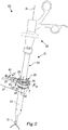
- Figure 2 is a detailed view of an arrangement 21 for minimal invasive intervention according to a first embodiment of the invention and Figures 3a-c are cross-sectional views of variants of the arrangement 21 of Figure 2 .
- One or more of the surgical instruments 3, 5, 7 and the endoscope 9 may be used together with an arrangement 21 according to the invention.
- the arrangement 21 comprises a rotation body 23, a retaining device 25 and a position sensor 27.
- a main portion of the outer surface of the rotation body 23 follows a spherical contour.
- the rotation body 23 comprises a through-going hole 29 with an axial direction A1 for receiving a shaft 31 of a medical instrument 33, e.g. of one of the surgical instruments 3, 5, 7 or the endoscope 9.
- the through-going hole 29 allows an axial displacement of the shaft 31 in the axial direction A1 relative to the rotation body 23.
- the whole surface of rotation body 23, except for where the through-going hole 29 is located follows a spherical contour.
- Figure 2 further illustrates a trocar 34, through which the shaft 31 of the medical instrument 33 is inserted.
- the trocar 34 may be dispensed with such that the medical instrument 33 is directly inserted into the rotation body 23.
- the pattern 35 On the outer surface of the rotation body 23 there is pattern 35.
- the pattern 35 itself comprises information about where on the outer surface of the rotation body 23 a certain element of the pattern 35 is located. Examples of such patterns are known from EP 1963786 B1 .
- the pattern 35 may be an optical pattern or a magnetic pattern. An optical pattern is often preferable, since detection of a magnetic pattern may be influenced by metal of the medical instrument 33, or the magnetic pattern may itself influence the medical instrument 33.
- the position of the rotation body 23 in relation to the retaining device 25 in absolute coordinates. Further, by determining the three-dimensional position of a pivot point P for the rotational movement of the rotation body 23 in relation to retaining device 25, the position of the pivot point P being determined in relation to the surrounding environment, e.g. in relation to an operating room and/or to the patient 1, the position of the medical instrument 33 may be determined in absolute coordinates in relation to the surrounding environment. It is sufficient to determine the position of the pivot point P once, e.g. as a calibration before a minimal invasive intervention starts.
- the absolute position of the medical instrument 33 is known by knowing the position of the pivot point P in relation to the surrounding environment, which position may be determined once, plus knowing the position of the rotation body 23 in relation to the retaining device 25, which may be determined continuously or intermittently. Since the position of the retaining device 25 in relation to the surrounding environment is determined once before the minimal invasive intervention starts, there is no risk that the patient 1, the surgeon, or any assisting staff in the operating room, would obscure position signals sent out from the medical instrument, which could be the case with some prior art arrangements utilizing a transmitter in the medical instrument.
- the above-suggested kind of pattern further differs from some prior art patterns, which are able to measure relative positions, e.g. as a relative displacement, but where the pattern elements lack information about in which part of the pattern they are located.
- the retaining device 25 is adapted to at least partly surround the rotation body 23, such that the rotation body 23 is retained by the retaining device 25 in a manner allowing rotational movement of the rotation body 23 in relation to the retaining device 25. See Figures 3a and 3b , where the rotation body 23 has rotated about 20 degrees between the two views.
- the above-mentioned pivot point P for the rotation is located in the three-dimensional space defined by the retaining device 25, but in the free air inside of the retaining device 25.
- the retaining device 25 has an axial direction A2 going through the pivot point P. In a neutral position of the rotation body 23, as in Figure 3a , the axes A1 of the rotation body 23 and A2 of the retaining device 25 coincide. However, in Figure 3b the two axes A1 and A2 differ by the about 20 degrees.
- the retaining device 25 may comprise a housing, not illustrated, partially encircling the rotation body 23.
- the housing would in that case comprise an opening angle ⁇ allowing movement of the rotation body 23.
- the opening angle ⁇ may be centred around the axial direction A2 of the retaining device 25.
- the opening angle ⁇ may be chosen to be at least 25 degrees, preferably at least 30 degrees, more preferably at least 35 degrees and most preferably at least 40 degrees.
- the opening angle ⁇ is hence chosen to make it possible to move the instrument inside the body of the patient 1 in a desired way.
- the retaining device 25 may comprise a ring-shaped component 37 encircling the rotation body 23, as in the illustrated embodiment.
- the cross-section of the ring-shaped component 37 has a non-straight inner surface 39 adapted to retain the rotation body 23 in the retaining device 25.
- the inner surface 39 may have a cross-sectional curvature corresponding to that of the outer surface of the rotation body 23 but with a slightly larger radius. See the cross-sectional view of Figure 3a .
- the cross-section of the inner surface 39 may comprise a plurality of straight lines, e.g. two.
- the cross-section of the inner surface 39 is adapted to retain the rotation body 23 in the retaining device 25.
- the ring-shaped component 37 allows a greater opening angle ⁇ as compared to the above-described housing.
- the arrangement 21 further comprises the at least one position sensor 27 for determining a position in at least two coordinates of the pattern 35 on the outer surface of the rotation body 23.
- the at least one position sensor 27 is located at, in or on the retaining device 25, such that it has a free view onto the pattern 35.
- the at least one position sensor 27 is wiredly or wirelessly connected to a system 65, which system 65 is further described below.
- the at least one position sensor 27 comprises a camera, which is located in the retaining device 25.
- the camera has a free field of view through a channel 41 in a handle portion 43 of the retaining device 25.
- the camera is used to determine the position of the pattern 35 on the surface of the rotation body 23.
- the camera may be of a two-dimensional kind. It may have a distance in the range of 1-50 mm from the pattern, preferably in the range of 5-40 mm and more preferably in the range of 10-30 mm. It is preferred to use a non-contact sensor, such as the illustrated camera.
- the retaining device 25 can be disconnected at a connection 45 into a proximal portion 47 and a distal portion 49.
- the proximal portion 47 then comprises the at least one position sensor 27, i.e. the camera, and the electrical wiring of the camera.
- the distal portion 49 comprises the ring-shaped component 37.
- the distal portion 49 which is adapted to be closest to the patient 1, may be efficiently cleaned or sterilized, while the proximal portion 47 may be cleaned in a more lenient way.
- the rotation body 23, the distal portion 49 of the retaining device 25, and the medical instrument 33 may e.g. be run in a cleaning process, such as a sterilization process, e.g. in an autoclave.
- a linear sensor 51 located inside the rotation body 23, as may be gleaned from Figure 3a , illustrating an example of a linear sensor 51.
- at least a portion 53 of the shaft 31 of the medical instrument 33 adapted to go through the through-going hole 29 comprises a conductive surface, while there is a contact, e.g. a metal sphere 55 located at a surface of the through-going hole 29.
- the sphere 55 is biased, e.g. by a spring 57, towards the through-going hole 29 and hence towards the shaft 31 of the medical instrument 33.
- the trocar is dispensed with.
- the linear sensor 51 in that case functions as a kind of slide resistor.
- the linear sensor 51 is connected to the system 65, e.g. in a way as described below in conjunction with Figure 5 .
- the shaft pattern 59 preferably is of the kind of pattern described above regarding the pattern 35 on the rotation body 23.
- the axial position sensor 61 may be a camera located within the rotation body 23, e.g. facing the through-going hole 29 and thus the shaft 31 of the medical instrument 33.
- the rotation body 23 is at least partly transparent, a single sensor, e.g. a single camera, may be utilized both as the position sensor for determining the position of the pattern 35 on the rotation body 23 and as the axial position sensor for determining the position of the shaft pattern 59 on the shaft 31 of the medical instrument 33.
- the rotation body 23 may comprise or be constituted by a transparent material or the rotation body 23 may comprise openings making it possible to look through the rotation body 23 onto the shaft 31 of the medical instrument 33.
- the shaft pattern 59 may be used for measuring tensioning of the shaft 31, e.g. when applying a force and/or a torque to the shaft 31.
- the force and/or the torque may be applied by the surgeon handling the medical instrument 33.
- the material of the shaft 31 is tensioned, the appearance of the shaft pattern 59 will change slightly.
- the shaft pattern 59 may be compressed or extended and/or the shaft pattern 59 may change its angular orientation. These changes of the shaft pattern 59 may be determined to determine the tension applied to the shaft 31. If comparing to the shaft pattern 59 of an untensioned shaft 31 and knowing material properties, absolute values for the tensioning may be determined. Material properties of the shaft 31 may be determined by making calibration tests of the shaft 31 before the medical instrument 33 is placed in the arrangement 21, e.g. as a step in a production process.
- the medical instrument 33 and the arrangement 21 form part of a kit 63. See Figure 2 .
- the medical instrument 33 may be an instrument for grasping, suturing, suction, irrigation, extraction, cutting, coagulation, stapling or viewing.
- the term medical instrument as used herein further comprises instruments used for other interventions, such as an endoscope, a biopsy needle, a veress needle or a catheter.
- the arrangement 21 is part of the system 65, which is a system for follow-up of the minimal invasive intervention.
- the system 65 comprises one or more arrangements 21 as disclosed herein, or one or more kits 63 as disclosed herein, and a memory 67 for storing data of determined positions.
- the memory may be located in a central processing unit 69 but may also be a separate unit.
- the memory 67 may, as a complement or an alternative, be located in an external location.
- FIG 4 illustrates an arrangement 71 for minimal invasive intervention according to a second embodiment of the invention.
- the arrangement 71 comprises a rotation body 73, a retaining device 75 and a position sensor 77.
- the rotation body 73 may be in the form of a cylindrical sleeve adapted to receive a medical instrument, or the rotation body 73 may form part of a shaft 81 of the medical instrument 83, as is illustrated in Figure 4 .
- a second position sensor 79 located at an angle to the position sensor 77, e.g. at a right angle in relation to the position sensor 77, as is indicated by dashed lines in Figure 4 .
- the outer surface of the rotation body 73 follows a cylindrical contour.
- the retaining device 75 comprises a through-going hole 85 with an axial direction A3 for receiving the shaft 81.
- the through-going hole 85 allows an axial displacement of the shaft 81 in the axial direction A3 relative to the retaining device 75.
- a pattern 87 On at least a portion of the outer surface of the rotation body 73, i.e. for this embodiment on the shaft 81, there is a pattern 87. Examples of such patterns are known from EP 1963786 B1 and are described above in conjunction with Figure 2 . By utilizing such a pattern 87, it is possible to determine the position of the rotation body 73 in relation to the retaining device 75 in absolute coordinates.
- the cylindrical contour allows rotation of the medical instrument 83 around the axis A3 in relation to the retaining device 75 and linear translations along the axis A3.
- Figure 5 illustrates an arrangement for minimal invasive intervention according to a third embodiment of the invention.
- Many details of the rotation body 23 and the retaining device 25 correspond to that of the first embodiment and will not be described again. However, there are some differences, as described below.
- the axial position sensor 51 is comprised in the trocar 34' and is located above the rotation body 23.
- the shaft 31 of the medical instrument is inserted into a sleeve 38.
- the linear sensor 51 operates in the way described above in conjunction with Figure 3a .
- the sphere 55 abuts against the sleeve 38, which has a conductive surface.
- the sleeve 38 is locked to the shaft 31 of the medical instrument by a locking means 38a.
- the sleeve 38 and the sphere 55 together form a slide resistor, which is used for determining the axial position of the shaft 31.
- the slide resistor is connected by an electrical wire 38b to the system 65.
- Figure 6 illustrates an arrangement for minimal invasive intervention according to a fourth embodiment of the invention.
- the axial position sensor is comprised in the trocar 34"
- the axial position sensor comprises a camera 61, as described above in conjunction with Figure 3c .
- the trocar also optionally comprises seals 88a, 88b, which e.g. may stop gas from leaving the trocar 34".
- There is a sleeve 89 comprising a shaft pattern 91 located around the shaft 31 of the medical instrument and the camera 61 utilizes the shaft pattern 91 to determine the axial position of the shaft.
- the sleeve 89 is locked to the shaft 31, such that it follows the shaft 31 when moving axially.
- the shaft pattern could be located directly on the surface of the shaft 31 and the sleeve 89 may then be dispensed with.
- Figure 7 illustrates an arrangement for minimal invasive intervention according to a fifth embodiment of the invention.
- a shaft pattern 91 located directly on the surface of the shaft 31.
- a sleeve 89 similar to that of the fourth embodiment may be utilized.
- the camera 27 utilizes the shaft pattern 91 to determine the axial position of the shaft 31.
- the fifth embodiment differs from the first to fourth embodiments in that the retaining device 75' allows the shaft 31 to rotate 3-dimensionally in a bearing 93 formed by an inner surface of the retaining device 75' and which bearing 93 in this exemplary embodiment is ring-shaped. See Figures 7a and 7b .
- the ring-shaped bearing 93 is seen as two tip-shaped abutments 95a, 95b of the ring-shaped component 37'.
- At least one position sensor e.g. a camera, has a free view to the shaft pattern 91, e.g. through a transparent window 97.
- the at least one position sensor may view the shaft pattern 91 in the plane of the ring-shaped bearing 93 or in a plane slightly above, as is illustrated, or below.
- the shaft 31 is free to move axially, e.g. up and through the retaining device 75'.
- the shaft 31 is rotatable in all three dimensions around the ring-shaped bearing 93.
- FIG. 7b illustrating the shaft 31 in an angled position as compared to the neutral axial position of Figure 7a .
- the shaft 31 may rotate around its longitudinal axis.
- the rotation body forms part of the shaft 31.
- the same pattern, i.e. the shaft pattern 91, and the same position sensor 27, the camera, may hence be used for determining the rotation in the ring-shaped bearing 93, as in Figure 7b , the axial position of the shaft and the rotation of the shaft 31 around its longitudinal axis.
- the shaft pattern 91 may be utilized for determining a tension applied to the shaft 31, as described above.
- the arrangement of the fifth embodiment is also appropriate for other applications than a minimal invasive intervention, e.g. as a joystick or as an input device for a computer game or an input devices for a vehicle, vessel or aircraft.
- the arrangement may further be used to determine how much a linear sensor, located along the shaft, or the shaft, is angled.
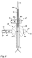
- Figure 8 illustrates a method comprising determining a position of a medical instrument by means of an arrangement for minimal invasive intervention as disclosed herein, or a kit for minimal invasive intervention as disclosed herein. Method steps with dashed contour lines are optional, as is further described below.
- the position of the pattern may be determined in three coordinates, preferably in absolute coordinates.
- the method may further comprise 1010. Calibrating the position of a pivot point for the rotational movement of the rotation body in relation to the retaining device, the position of the pivot point being determined in relation to a surrounding environment, such as an operating room and/or a patient.
- the position of the pivot point By determining the three-dimensional position of the pivot point for the rotational movement of the rotation body in relation to retaining device, the position of the pivot point being determined in relation to the surrounding environment, e.g. in relation to an operating room and/or the patient, the position of the medical instrument may be determined in absolute coordinates in relation to the surrounding environment. It is sufficient to determine the position of the pivot point once, e.g. as a calibration before a minimal invasive intervention starts. It is assumed that the at least one position sensor is located in a known position in the retaining device with a known distance to the rotation body.
- the absolute position of the medical instrument is known by knowing the position of the pivot point in relation to the surrounding environment, which position may be determined once, plus knowing the position of the rotation body in relation to the retaining device, which may be determined continuously or intermittently. Since the position of the retaining device in relation to the surrounding environment is determined once before the minimal invasive intervention starts, there is no risk that the patient, the surgeon, or any assisting staff in the operating room, would obscure position signals sent out from the medical instrument, which could be the case with some prior art arrangements utilizing a transmitter in the medical instrument.
- the method may further comprise 1030. Determining an axial position of the shaft of the medical instrument in the hole.
- step 1040 comprises utilizing both the position of the pattern on the rotation body and the axial position: 1040. Utilizing the determined position of the pattern and the determined axial position to determine the position of the medical instrument. Thereby movements of the medical instrument around the rotation body, i.e. rotations, and linear translations may be determined.
- steps 1030, 1040 may e.g. be performed if the medical instrument comprises a shaft and the rotation body comprises a hole with an axial direction for receiving the shaft.
- the method may further comprise 1050.
- the shaft pattern on the shaft or sleeve for determining a tension applied to the shaft or sleeve and/or for determining axial position of the shaft or the sleeve.
- Step 1050 may be performed before, in parallel to or after step 1040.
- the method may further comprise
- step 1010 By knowing at least two positions, the displacement of the instrument between these two positions may be determined. This is illustrated in Figure 5 by arrow 1060 going back to step 1020. As mentioned above, it is sufficient to perform step 1010 once, although step 1010 optionally may be repeated as well.
- the method may further comprise
- the displacement motion e.g. the displacement path
- the displacement velocity, the displacement acceleration and/or the displacement smoothness may be determined.
- the displacement velocity, the displacement acceleration and/or the displacement smoothness may be determined from the mathematical derivatives of the determined displacements.
- the shaft or sleeve comprises a shaft pattern
- the shaft pattern may be used for monitoring the tension applied to the shaft or sleeve.
- the method may further comprise 1080. Storing data about the determined positions of the medical instrument.
- the method may in that case also comprise 1090. Using the data for statistical follow-up.
- the stored data may be used for follow-up of training of surgeons.
- stored data may be used for quality assurance and/or quality follow-up of minimal invasive intervention, e.g. of training interventions or real-world interventions.
Landscapes
- Health & Medical Sciences (AREA)
- Life Sciences & Earth Sciences (AREA)
- Surgery (AREA)
- Engineering & Computer Science (AREA)
- Molecular Biology (AREA)
- Public Health (AREA)
- Veterinary Medicine (AREA)
- Biomedical Technology (AREA)
- Heart & Thoracic Surgery (AREA)
- Medical Informatics (AREA)
- Nuclear Medicine, Radiotherapy & Molecular Imaging (AREA)
- Animal Behavior & Ethology (AREA)
- General Health & Medical Sciences (AREA)
- Pathology (AREA)
- Oral & Maxillofacial Surgery (AREA)
- Physics & Mathematics (AREA)
- Optics & Photonics (AREA)
- Robotics (AREA)
- Biophysics (AREA)
- Radiology & Medical Imaging (AREA)
- Endoscopes (AREA)
Description
- The present disclosure relates to an arrangement for minimal invasive intervention. The disclosure further relates to a medical instrument, a kit comprising such an arrangement, a system for follow-up of a minimal invasive intervention and a method comprising determining a position of a medical instrument by means of such an arrangement.
- Minimal invasive surgery aims to reduce tissue trauma, bleeding and to improve the healing process. Such surgery is performed through tiny incisions in the skin, often only a few millimeters, through which medical instruments are inserted. A miniature camera attached to a light tube, i.e. an endoscope, may be inserted through one of the incisions to provide the surgeon of a view of the operation. The surgeon may then explore what is wrong, remove unwanted objects or body parts or repair what is inside the body etc. An example is laparoscopic surgery, which may be performed in the abdomen. Minimal invasive surgery may be performed on a body of a human being or an animal.
- In order to train surgeons or veterinarians before operating on a living being, interventions may be performed on a corpse of a dead human being or animal. It is also feasible to train surgeons or veterinarians utilizing training material, e.g. models made of rubber or plastic, as e.g. disclosed in patent document
US 2005/0142525 A1 by Cotin et al. Training may also be performed by simulation in virtual reality, as e.g. disclosed inpatent document US 8,007,282 B2 disclosing a medical simulation interface apparatus. - As part of the training, it may be of interest to track the movements of the instrument utilized inside the body. In the medical simulation interface apparatus disclosed by
US 8,007,282 B2 , it is, for example, possible to track movements of the instruments by means of a plurality of mechanical interfaces. - However a difference between training, being in virtual reality or with model materials, and real world minimal invasive surgery, is the hygienic demands applicable when operating on living beings. There is then often a desire to be able to sterilize or clean the objects and medical instruments. Therefore arrangements used for tracking movements of instruments in prior art training apparatuses, as in
US 8,007,282 B2 , have been found to be unsuitable for use in real world minimal invasive surgery. - Although the training apparatuses become better and better, there is still a step between training and real world minimal invasive surgery.
- Document
WO 2014/057853 A1 relates according to its abstract to an insertion system for detecting operation assistance information regarding the insertion amount and rotational quantity, as well as the tip position, shape, and the like of an insertion member in order to accurately determine the position and direction of the insertion member. The insertion system has: an insertion unit having at least a gripping part, an insertion area inserted into the subject, and an insertion channel passing from the base end to the tip of the insertion area; an insertion member inserted into the insertion channel; a first status detector positioned in the insertion unit, for detecting information for calculating the insertion amount in the insertion direction along the longitudinal direction of the inserted insertion member and/or and the rotational quantity of rotation about the central axis of the insertion member along the insertion direction; and a calculation unit for calculating operation assistance information on the basis of the detection results of the first status detector. - Document
EP 2 147 630 A2 relates according to its abstract to an endoscopic surgical system. Endoscope position/attitude information acquisition means, which acquires position/attitude information of an endoscope is connected to a control device, which controls a motor box, which actively actuates a surgical instrument, and the control device utilizes the position/attitude information to adjust a control signal of the motor box so that a position deviation of the surgical instrument within an endoscope image when the position of the endoscope changes is prevented from occurring. - Document
US 2007/135803 A1 relates according to its abstract to an apparatus for use in a transluminal procedure. The apparatus, comprising, for example, a housing having a guide lumen and a seal proximal to a distal end of the housing that extends across and completely seals the guide lumen; a fixation element in the housing and adapted to secure the distal end of the housing to tissue; and a channel extending through the side wall of the housing having an outlet in communication with the lumen distal of the seal. Methods are also provided. For example, a method includes, performing a transluminal procedure by: securing a datum and position indicator to a wall of a target lumen; forming an opening in the wall; advancing an instrument through the opening; and tracking the advancement of the instrument using the datum and position indicator. - The object of the present disclosure is to overcome or ameliorate at least one of the disadvantages of the prior art, or to provide a useful alternative.
- The object above may be achieved by the subject-matter of
claim 1. Embodiments are set forth in the appended dependent claims, in the following description and in the drawings. - Thus, in a first aspect of the present invention there is provided an arrangement for minimal invasive intervention according to
claim 1. The arrangement comprises a rotation body, a retaining device and at least one position sensor. The rotation body is adapted to receive a medical instrument adapted for minimal invasive intervention, or, as an alternative or a complement, the rotation body itself forms a part of a medical instrument. The medical instrument comprises a shaft. At least a portion of a surface of the rotation body comprises a pattern adapted for determining a position of the pattern, the pattern being an optical pattern. The retaining device is adapted to at least partly surround the rotation body, such that the rotation body is retained by the retaining device in a manner allowing rotational movement of the rotation body in relation to the retaining device. The at least one position sensor is adapted for determining a position in at least two coordinates of the pattern of the rotation body. The at least one position sensor is located at, in or on the retaining device. The at least one position sensor is an optical position sensor, such as a camera. The pattern comprises information about position in absolute coordinates, so that the position of the rotation body in relation to the retaining device can be determined in absolute coordinates by utilizing the pattern. - The term minimal invasive intervention as utilized herein comprises minimal invasive surgery, as described above. The term minimal invasive intervention as utilized herein also comprises other kinds of interventions. Examples of such interventions are endoscopy, i.e. looking inside the body, e.g. by means of the above-mentioned endoscope, biopsy or usage of a catheter.
- The minimal invasive intervention may be performed on a body of a human being or an animal. Further in order to train surgeons or veterinarians before operating on a living being, interventions may be performed on a corpse of a dead human being or animal. It is also feasible to perform such interventions on training material, e.g. models made of rubber or plastic. Hence the arrangement as disclosed herein is not only suitable for real world minimal invasive interventions, but is also suitable for use in a surgical training apparatus. The arrangement may further be part of a medical simulator for performing training in virtual reality. In addition, the arrangement may be utilized when performing robotic surgery, i.e. using robotic systems to aid in surgical procedures. In that case, data determined by the position sensor may be used for providing feedback to the robotic control system.
- The arrangement as disclosed herein has the advantage of being usable both for training purposes and in the real world when performing an intervention on a living being. The person utilizing the arrangement will therefore experience a smooth transfer between a training situation and a real patient situation. The same or a similar medical instrument may be used both during training and during real world minimal invasive intervention. Thereby it is possible to measure and follow a learning curve for the person performing training. The same medical instrument can be used in virtual reality, for training on model materials, for training on corpses, for interventions on patients and for robotic surgery. There may thus be an authentic situation during the whole training. Further, there will be no steps in the learning curve when changing between different training environments, as is the case with today's training methods, since with the arrangement as disclosed herein, the same medical instrument may be used in the different training environments. By utilizing the arrangement as disclosed herein for training of the surgeon, he or she will have obtained a certain level of skill before operating on patients. Today, it may occur that a surgeon actually trains on the first patients while improving his or her skill, but with an arrangement as disclosed herein that level may be reached before the surgeon starts operating on real patients.
- The arrangement is configured such that the components comprised therein, which are to be in contact or adjacent to the body on which the minimal invasive intervention is performed, can be adequately cleaned or sterilized. The materials may be chosen to be adequate for cleaning or sterilization. Purely as an example, the arrangement may be dismantled by disconnecting the position sensor from the retaining device or the position sensor may form a proximal portion of the retaining device, which may be disconnected from a distal portion. Thereafter the rotation body, the retaining device, or its distal portion, and the medical instrument may be run in a cleaning process, such as a sterilization process, e.g. in an autoclave. As an alternative, the rotation body, the retaining device and/or the medical instrument may be for single use, e.g. being disposed of after usage. This contributes to the versatility of the arrangement, such that it is suitable both for training, as described above, and for real world minimal invasive intervention.
- Examples of medical instruments are instruments for grasping, suturing, suction, irrigation, extraction, cutting, coagulation, stapling or viewing. The term medical instrument as used herein further comprises instruments used for other interventions, such as an endoscope, a biopsy needle, a veress needle or a catheter. A medical instrument adapted for minimal invasive intervention may be used together with a trocar, through which the medical instrument is inserted. The trocar typically comprises an obturator and a cannula. The term medical instrument, as used herein, may also comprise the combination of a medical instrument and a trocar. As mentioned above, the instrument may be introduced through a tiny incision in the skin. The instrument may also be introduced orally or anally.
- When performing certain operations, such as neuro operations or endonasal operations, it is important to know the position of the medical instrument in order to minimize or avoid the risk of damage to the patient. By e.g. placing the arrangement in a known position relative to the skull of the patient, the arrangement as disclosed herein is able to accurately determine the position of the instrument.
- The term shaft as used herein comprises both rigid shafts and flexible shafts. It is e.g. known to the skilled person that medical instruments used for endoscopy may have flexible shafts. Purely as an example a shaft of an endoscope used for gastroscopy, bronchoscopy or colonoscopy may be flexible. A catheter may comprise a stiff shaft or a flexible shaft, while a biopsy needle or a veress needle comprises a stiff shaft.
- The pattern may cover a portion of the surface of the rotation body, a main portion of its surface or substantially the entire surface. The pattern is preferably located on an outer surface of the rotation body. However, if the rotation body is at least partly transparent, e.g. comprising openings or being of a transparent material, there may, as an alternative or a complement, be a pattern on an inside surface, e.g. on a wall of a hole in the rotation body, or in an interior of the rotation body.
- The pattern provides information for determining a position of the pattern by the position sensor. The pattern may be deliberately added to the surface of the rotation body. The pattern may be printed or laser-engraved on the surface of the rotation body. The pattern on the rotation body may be an optical pattern or a magnetic pattern. The pattern is used to determine a position of the shaft of the medical instrument. By knowing the properties of the shaft, e.g. its length, it is thereby possible to determine a position of a tip of the shaft and hence follow the actions of the surgeon.
- The pattern on the rotation body comprises information about position in absolute coordinates. Preferably the pattern itself comprises information about where on the surface of the rotation body a certain element of the pattern is located. The pattern thus preferably comprises information how different pattern elements are located in relation to each other. Examples of such patterns are known from
EP 1963786 B1 disclosing a pattern comprising a plurality of pattern groups, wherein a pattern group comprises at least one node point and at least one information point. The node points are used for determining the position in the camera window, while information points are used for determining the absolute position of the pattern group. This kind of pattern further differs from some prior art patterns, which are able to measure relative positions, e.g. as a relative displacement, but where the pattern elements lack information about in which part of the pattern they are located. - The position of the pattern on the rotation body is determined in relation to the retaining device in at least two coordinates. The two coordinates may relate to two different coordinate axes, which preferably are orthogonal, e.g. Cartesian coordinate axes x and y. The two coordinates may then represent a rotation in x-direction and in y-direction of the rotation body. As an alternative, the two coordinates may e.g. represent rotation in z-direction and translation in z-direction. It has been found when comparing a beginner to an expert that the largest differences may be found in two coordinates, e.g. x-rotation and y-rotation. Hence, it may be sufficient to follow two coordinates in order to follow up the training, although three coordinates may be useful for a more accurate follow-up.
- The position of the pattern of the rotation body may be determined in at least three coordinates. The three coordinates relate to a three-dimensional space. They may relate to a Cartesian coordinate system, a spherical coordinate system or a cylindrical coordinate system. Utilizing three coordinates is useful when utilizing the arrangement for determining a 3-dimensional position of the medical instrument. It is also useful for follow-up of training or for quality assurance.
- A portion of the shaft of the medical instrument may itself form the rotation body or a sleeve adapted to be located around the medical instrument may form the rotation body.
- The rotation body may comprise a hole with an axial direction for receiving the shaft of the medical instrument. The hole allows an axial displacement of the shaft in the axial direction relative to the rotation body. If a trocar is utilized as the medical instrument, the rotation body is adapted for receiving the shaft of the trocar, which in turn is adapted for receiving the shaft of another medical instrument. The hole may go through the rotation body, i.e. be a through-going hole. The hole may pass a centre of the rotation body. The hole suitably is substantially straight having a diameter adapted to the outer diameter of the shaft of the medical instrument. The hole allows movement of the medical instrument in the axial direction of the hole, i.e. a linear translation in relation to the rotation body.
- Alternatively, dependent on configuration of the arrangement, the retaining device may comprise a hole with an axial direction for receiving the shaft of the medical instrument. The hole may go through the retaining device, i.e. be a through-going hole. The hole allows an axial displacement of the shaft in the axial direction relative to the retaining device. In that case the retaining device may constitute a bearing for the medical instrument, which is further described below.
- At least a portion of an outer surface of the rotation body may follow a spherical contour. Preferably a main portion of the surface, or substantially the entire surface, may follow the spherical contour. Purely as an example, the rotation body may have the contour of a sphere with a hole passing the centre of the sphere. The pattern may then be located on the outer surface of the sphere. The spherical contour has been found to be advantageous, since the rotation body then may be utilized as a ball joint, located outside but adjacent to the body of the patient and facilitating precise movement of the medical instrument inside the body of the patient. The spherical contour allows movements in all three dimensions of the medical instrument. If combined with the hole of the rotation body as described above, the medical instrument may be rotated around the rotation body as a ball joint and linearly translated along the axial direction through the hole. In addition, the medical instrument may be rotated around its longitudinal axis, i.e. around an axis of the shaft.
- As an alternative to the spherical contour, at least a portion of an outer surface of the rotation body may follow a cylindrical contour. Preferably a main portion of the surface or substantially the entire surface may follow the cylindrical contour. Purely as an example, the rotation body may have the contour of a cylinder with a hole passing the centre of the cylinder. The pattern may then be located on the outer surface of the cylinder. The rotation body may also be in the form a sleeve adapted to be located around the medical instrument or the rotation body may form a portion of the shaft, e.g. in case the retaining device provides the hole. The cylindrical contour allows rotation around the longitudinal cylinder axis. If combined with the hole as described above, and assuming that the cylinder axis coincides with the axial direction of the hole, the medical instrument may be rotated around its cylinder axis and linearly translated along the cylinder axis.
- The relative movability between the parts of the arrangement, e.g. between two or more of the rotation body, the shaft of the medical instrument and the trocar, i.e. if they are fixed to each other or rotatable in relation to each other, may be selected dependent on the desired number of coordinates used to determine the position of the pattern of the rotation body and of an axial position, as is further described below, i.e. the desired number of degrees of freedom. The shaft of the medical instrument may e.g. be torsional-rigidly connected to the rotation body in such a way that a rotation of the shaft is transferred to the rotation body. The shaft may be directly connected to the rotation body or it may be connected to a trocar, which may be located between the shaft and the rotation body, with the shaft being torsional-rigidly connected to the rotation body via the optional trocar. The trocar may be torsional-rigidly connected to the shaft of the medical instrument, but may alternatively be cylindrically rotatable in relation to the rotation body. The shaft of the medical instrument may be cylindrically rotatable in relation to the trocar or may be fixed in relation to the trocar.
- The at least one position sensor and the pattern of the rotation body may be adapted for determining the position of the pattern in three coordinates. The three coordinates relate to coordinate axes spanning a three-dimensional space, e.g. a Cartesian coordinate system, a spherical coordinate system or a cylindrical coordinate system.
- By utilizing absolute coordinates and by determining the three-dimensional position of a pivot point for the rotational movement of the rotation body in relation to retaining device, the position of the pivot point being determined in relation to the surrounding environment, e.g. in relation to an operating room and/or the patient, the position of the medical instrument may be determined in absolute coordinates in relation to the surrounding environment. It may be assumed that the at least one position sensor is located in a known position in the retaining device with a known distance to the rotation body. It is then sufficient to determine the position of the pivot point once, e.g. as a calibration before the minimal invasive intervention starts. There is hence no need to continuously make such three-dimensional calibration during the minimal invasive intervention, since the absolute position of the medical instrument is known by knowing the position of the pivot point in relation to the surrounding environment, which position may be determined once, plus knowing the position of the rotation body in relation to the retaining device, which may be determined continuously or intermittently. Since the position of the retaining device in relation to the surrounding environment is determined once before the minimal invasive intervention starts, there is no risk that the patient, the surgeon, or any assisting staff in the operating room, would obscure position signals sent out from the medical instrument, which could be the case with some prior art arrangements utilizing a transmitter in the medical instrument.
- The at least one position sensor may be a non-contact sensor. If more than one sensor is utilized they may be of different types. They may be located in an angled relationship to each other, e.g. perpendicular to each other.
- The pattern is an optical pattern and the at least one position sensor is an optical position sensor, such as a camera. The camera may be of a two-dimensional kind. It may have a distance in the range of 1-50 mm from the pattern, preferably in the range of 5-40 mm and more preferably in the range of 10-30 mm.
- As an alternative or a complement, not included in
claim 1, the pattern may be a magnetic pattern and the at least one position sensor may be a magnetic sensor. - An optical pattern may be preferable, since detection of a magnetic pattern may be influenced by metal of the medical instrument, or the magnetic pattern may itself influence a medical instrument comprising metal.
- The arrangement may further comprise a sensor for determining an axial position of the shaft. The axial position may be determined in relation to the rotation body, e.g. to the above-mentioned hole, and/or in relation to the retaining device. The sensor may be located in the rotation body or in the retaining device.
- The sensor for determining an axial position of the shaft may be a linear sensor. The axial position sensor may be at least partly located inside the rotation body, e.g. at the wall of the hole. This may be the case when the rotation body follows a spherical contour. As an alternative, the axial position sensor may be located in the trocar. Purely as an example, at least a portion of the shaft of the medical instrument may comprise a conductive surface, while there may be a contact, e.g. a metal sphere, located at a surface of the wall of the hole or in the trocar. The sphere may be biased, e.g. by a spring, towards the shaft of the medical instrument. The sensor in that case functions as a slide resistor.
- As an alternative to utilizing the above-described linear sensor for determining the axial position of the shaft, there may be a shaft pattern on the shaft of the medical instrument, or on a sleeve located around the shaft, the position of the shaft pattern being determinable by an axial position sensor. The shaft pattern in that case preferably is of the kind described above regarding the pattern on the rotation body. The axial position sensor may be a position sensor of the same kind as the position sensor for determining the pattern on the rotation body, e.g. a camera located within the rotation body, e.g. facing the hole and thus the shaft of the medical instrument or a camera located in the trocar. Thereby it is possible to determine an axial position of the shaft, and hence to determine a linear translation of the shaft. The shaft pattern may also be utilized to determine rotation of the shaft around its length axis, e.g. by means of the camera.
- If the rotation body is at least partly transparent, a single sensor, e.g. a single camera located in, on or at the retaining device, may be utilized both for determining the position of the pattern on the rotation body and for determining the position of the shaft pattern on the shaft of the medical instrument. Purely as an example, the rotation body may comprise or be constituted by a transparent material or the rotation body may comprise openings making it possible to look through the rotation body onto the shaft of the medical instrument. The same pattern, e.g. located along a portion of the shaft of the medical instrument, may be used both for determining rotation of the medical instrument and as the shaft pattern for determining linear translations, the shaft pattern in that case constituting the pattern of the rotation body, such that a single pattern is sufficient. Utilizing the shaft pattern is for example suitable when the rotation body follows a spherical contour and/or follows a cylindrical contour.
- If a part of the shaft forms the rotation body, or if a sleeve on the shaft forms the rotation body, the axial position may be determined in relation to the retaining device. The rotation body may in that case follow a cylindrical contour.
- If utilizing an instrument, of which at least a portion of the shaft, or the sleeve, comprises a shaft pattern, the shaft pattern may, as an alternative or as a complement to a common force sensor such as a strain gauge, be used for measuring tensioning of the shaft, e.g. when applying a force and/or a torque to the shaft, e.g. a torsional tension. The force and/or the torque may e.g. be applied by the surgeon handling the medical instrument. When the material of the shaft is tensioned, the appearance of the shaft pattern will change slightly. Depending on the type of tension, the shaft pattern may be compressed or extended and/or the shaft pattern may change its angular orientation. These changes of the shaft pattern may be utilized to determine the tension applied to the shaft. If comparing to the shaft pattern of an untensioned shaft and knowing material properties, absolute values for the tensioning may be determined. Material properties of the shaft may be determined by making calibration tests of the shaft before the medical instrument is placed in the arrangement, or at least before the use of the instrument starts, e.g. as a step in a production process.
- The retaining device may provide a bearing for receiving the shaft and allowing the shaft to rotate 3-dimensionally in the bearing, the bearing also allowing axial translation relative to the bearing. In that case, the shaft may comprise a shaft pattern, or a sleeve with a shaft pattern may be located around the shaft. An inner surface of the retaining device may form the bearing. At least one position sensor, e.g. a camera, may be arranged to have a free view to the shaft pattern, e.g. through a transparent window. The at least one position sensor may view the shaft pattern in the plane of the bearing or in a plane slightly above or below the bearing. The shaft is free to move axially, i.e. up and down along the shaft through the retaining device. In addition, the shaft is rotatable in all three dimensions in the bearing, such that the shaft may be angled in relation to a neutral position of the shaft. Further, the shaft may rotate around the axis of the shaft. The bearing may be ring-shaped, i.e. form a ring around the shaft. In addition, the shaft pattern may be utilized for determining a tension applied to the shaft.
- In such an arrangement, i.e. the retaining device forming a bearing for the shaft, the rotation body may form part of the shaft or the sleeve may form the rotation body. The same pattern, i.e. the shaft pattern, and the same position sensor, e.g. the camera, may hence be used for determining the rotation in the bearing and the axial position of the shaft and further for the rotation of the shaft around its longitudinal axis. In addition, the shaft pattern may be utilized for determining a tension applied to the shaft, as described above. This embodiment of the arrangement may be positioned very close to the skin of the patient. As an option, this arrangement may be comprised in the trocar.
- This kind of arrangement, i.e. the retaining device forming a bearing for the shaft, is also appropriate for other applications than a minimal invasive intervention, e.g. as a joystick or as an input device for a computer game or an input devices for a vehicle, vessel or aircraft. The arrangement may further be used to determine how much a linear sensor located along the shaft, is angled in relation to a neutral position of the shaft. The arrangement may e.g. be used to determine if, or how much, an axis of a rotatable shaft in a bearing deviates from the intended axial direction. In that case the arrangement may constitute components of the bearing arrangement. The camera, or cameras, may then be located in the bearing housing. The arrangement may suitably be utilized in a spherical bearing. The sleeve may form an inner ring of a bearing. This kind of arrangement is also suitable for determining movements of a static shaft, e.g. a bolt used as a fastening means. The arrangement may suitably be used for properly aligning a rotatable shaft.
- Two or more arrangements with the retaining device forming a bearing for the shaft may be located along the shaft of the same medical instrument. In that case, the axial position of the shaft and the rotation of the shaft around its longitudinal axis may be determined and, in addition, the shaft pattern may be utilized for determining a tension, e.g. a torsional tension, applied to the shaft. By utilizing two interspaced arrangements, the tension, e.g. the torsional tension, may be determined with high accuracy.
- As an example, there is provided a medical instrument for minimal invasive intervention. The medical instrument comprises a shaft, at least a portion of the shaft comprises a pattern for determining a position of the shaft and hence of the medical instrument. Preferably the pattern of the shaft comprises information about position in absolute coordinates. Suitable patterns are described above.
- In a third aspect of the present invention, there is provided a kit comprising an arrangement for minimal invasive intervention as disclosed herein and a medical instrument for minimal invasive intervention. The medical instrument comprises a shaft. As mentioned above, the term medical instrument, as used herein, also comprises a trocar, through which another medical instrument is inserted.
- In case the rotation body comprises a hole as described herein, the medical instrument may be adapted to be arranged with the shaft going through the hole of the rotation body of the arrangement.
- The rotation body may form a sleeve adapted to be located along, and at least partly around, a portion of the shaft of the medical instrument. The sleeve may be translationally movable in relation to the shaft allowing linear translation of the shaft or the sleeve may be fixedly attached to the shaft. As an alternative, or a complement, the rotation body may constitute a portion of the shaft of the medical instrument.
- As mentioned above, the rotation body may be a separate unit, e.g. following the contour of a sphere or a cylinder adapted to be located around the shaft of the medical instrument. In that case the pattern is located on the surface of the rotation body.
- A portion of the shaft, or a portion of the sleeve if located along the shaft of the medical instrument, may comprise a shaft pattern for determining a position of the shaft, as is described herein. Preferably the shaft pattern comprises information about position in absolute coordinates.
- In a fourth aspect of the present invention, there is provided a system for follow-up of a minimal invasive intervention. The system comprises an arrangement for minimal invasive intervention as disclosed herein, or a kit for minimal invasive intervention as disclosed herein, and a memory for storing data of determined positions determined by the at least one position sensor. The system comprises one or more arrangements for minimal invasive intervention. The memory may be located in a central processing unit but may also be a separate unit. The memory may, as a complement or an alternative, be located in an external location, wiredly or wirelessly connected to the position sensor of the arrangement.
- In a fifth aspect of the present invention, there is provided a method according to claim 12 for training surgeons or veterinarians by simulation in virtual reality, by utilizing training material, e.g. models made of rubber or plastic and/or by performing intervention on a corpse of a dead human being or animal. The method comprises determining a position of a medical instrument by means of an arrangement for minimal invasive intervention as disclosed herein, or a kit for minimal invasive intervention as disclosed herein. The method comprises
- determining in at least two coordinates a position of the pattern on the surface of the rotation body by means of the at least one position sensor, the pattern comprising information about position in absolute coordinates, so that the position of the rotation body in relation to the retaining device can be determined in absolute coordinates by utilizing the pattern,
- utilizing the determined position of the pattern to determine the position of the medical instrument.
- As described above, the position of the pattern may be determined in three coordinates, preferably in absolute coordinates.
- The method may further comprise
- calibrating the position of a pivot point for the rotational movement of the rotation body in relation to the retaining device, the position of the pivot point being determined in relation to a surrounding environment.
- By determining the three-dimensional position of the pivot point for the rotational movement of the rotation body in relation to retaining device, the position of the pivot point being determined in relation to the surrounding environment, e.g. in relation to an operating room and/or the patient, the position of the medical instrument may be determined in absolute coordinates in relation to the surrounding environment. It is sufficient to determine the position of the pivot point once, e.g. as a calibration before a minimal invasive intervention starts. It is assumed that the at least one position sensor is located in a known position in the retaining device with a known distance to the rotation body. There is hence no need to continuously make such three-dimensional calibration during the minimal invasive intervention, since the absolute position of the medical instrument is known by knowing the position of the pivot point in relation to the surrounding environment, which position may be determined once, plus knowing the position of the rotation body in relation to the retaining device, which may be determined continuously or intermittently. Since the position of the retaining device in relation to the surrounding environment is determined once before the minimal invasive intervention starts, there is no risk that the patient, the surgeon, or any assisting staff in the operating room, would obscure position signals sent out from the medical instrument, which could be the case with some prior art arrangements utilizing a transmitter in the medical instrument.
- The method may further comprise
- determining an axial position of the shaft of the medical instrument in the hole,
- utilizing the determined position of the pattern and the determined axial position to determine the position of the medical instrument.
- Thereby both movements of the medical instrument around the rotation body, i.e. rotations, and linear translations may be determined. These steps may e.g. be performed if the medical instrument comprises a shaft and the rotation body comprises a hole with an axial direction for receiving the shaft.
- In case a portion of the shaft, or the sleeve, comprises a shaft pattern for determining a position of the shaft, the shaft pattern comprising information about position in absolute coordinates, the method may further comprise
- utilizing the shaft pattern on the shaft or sleeve for determining a tension applied to the shaft or sleeve and/or for determining axial position of the shaft or the sleeve.
- The method may further comprise
- determining at least two positions of the medical instrument,
- utilizing the at least two positions to determine a displacement of the medical instrument.
- By knowing at least two positions, the displacement of the instrument between these two positions may be determined.
- The method may further comprise
- continuously or intermittently determining positions of the medical instrument,
- utilizing the positions to determine the displacement motion of the medical instrument.
- By continuously or intermittently determining positions of the medical instrument in the way disclosed herein the displacement motion, e.g. the displacement path, the displacement velocity, the displacement acceleration and/or the displacement smoothness, may be determined. The displacement velocity, the displacement acceleration and/or the displacement smoothness may be determined from the mathematical derivatives of the determined displacements. Further, in case the shaft or sleeve comprises a shaft pattern, the shaft pattern may be used for monitoring the tension applied to the shaft or sleeve.
- The method may further comprise
- storing data about the determined positions of the medical instrument, and
- as an option, using the data for statistical follow-up.
- The stored data may be used for follow-up of training of surgeons. In addition, or as a complement, stored data may be used for quality assurance and/or quality follow-up of minimal invasive intervention, e.g. of training interventions or real-world interventions.
- The present invention will hereinafter be further explained by means of non-limiting examples with reference to the appended drawings wherein:
- Fig. 1
- is a schematic view of an ongoing minimal invasive intervention,
- Fig. 2
- is a view of an arrangement for minimal invasive intervention according to a first embodiment of the invention
- Fig. 3a-c
- are cross-sectional views of the arrangement of
Figure 2 , - Fig. 4
- is a view of an arrangement according to a second embodiment,
- Fig. 5
- is a view of an arrangement according to a third embodiment,
- Fig. 6
- is a view of an arrangement according to a fourth embodiment,
- Fig. 7a-b
- are views of an arrangement according to a fifth embodiment, and
- Fig. 8
- illustrates a flowchart of a method according to the invention.
- It should be noted that the appended drawings are not necessarily drawn to scale and that the dimensions of some features of the present invention may have been exaggerated for the sake of clarity.
- The invention will, in the following, be exemplified by embodiments. It should however be realized that the embodiments are included in order to explain principles of the invention and not to limit the scope of the invention, defined by the appended claims. Details from two or more of the embodiments may be combined with each other.
-
Figure 1 illustrates an ongoing minimal invasive intervention in the form of a minimal invasive surgery in an abdomen of apatient 1, a so-called laparoscopic surgery. A surgeon performs the surgery through tiny incisions in the skin, often only a few millimeters, through whichsurgical instruments 3, 5, 7 are inserted. Anendoscope 9 comprising a miniature camera attached to a light tube, i.e. another type of medical instrument, is inserted through one of the incisions to provide the surgeon a view of the minimal invasive intervention, which view is projected on ascreen 10. The surgeon utilizes theinstruments 3, 5, 7 and theendoscope 9 to e.g. explore what is wrong, remove unwanted objects or body parts and/or repair what is inside the body. Thesurgical instruments 3, 5, 7 are inserted through the skin into the body of thepatient 1 through a hollow tube of arespective trocar trocars surgical instruments 3, 5. Theinstruments arrangements trocar 16 of theendoscope 9 is provided with a gas supply, e.g. nitrogen. Avalve 16a controls gas flow through ahose 16b connected to thetrocar 16. Such gas supply may be connected to any of the trocars, but it is common to connect the gas supply to thetrocar 16 of theendoscope 9. One or more of theother trocars trocar -
Figure 2 is a detailed view of anarrangement 21 for minimal invasive intervention according to a first embodiment of the invention andFigures 3a-c are cross-sectional views of variants of thearrangement 21 ofFigure 2 . One or more of thesurgical instruments 3, 5, 7 and theendoscope 9 may be used together with anarrangement 21 according to the invention. - The
arrangement 21 comprises arotation body 23, a retainingdevice 25 and aposition sensor 27. A main portion of the outer surface of therotation body 23 follows a spherical contour. Therotation body 23 comprises a through-goinghole 29 with an axial direction A1 for receiving ashaft 31 of amedical instrument 33, e.g. of one of thesurgical instruments 3, 5, 7 or theendoscope 9. The through-goinghole 29 allows an axial displacement of theshaft 31 in the axial direction A1 relative to therotation body 23. In the illustrated embodiment the whole surface ofrotation body 23, except for where the through-goinghole 29 is located, follows a spherical contour. -
Figure 2 further illustrates atrocar 34, through which theshaft 31 of themedical instrument 33 is inserted. As an alternative, thetrocar 34 may be dispensed with such that themedical instrument 33 is directly inserted into therotation body 23. - On the outer surface of the
rotation body 23 there ispattern 35. Preferably thepattern 35 itself comprises information about where on the outer surface of the rotation body 23 a certain element of thepattern 35 is located. Examples of such patterns are known fromEP 1963786 B1 . Thepattern 35 may be an optical pattern or a magnetic pattern. An optical pattern is often preferable, since detection of a magnetic pattern may be influenced by metal of themedical instrument 33, or the magnetic pattern may itself influence themedical instrument 33. - By utilizing such a
pattern 35 it is possible to determine the position of therotation body 23 in relation to the retainingdevice 25 in absolute coordinates. Further, by determining the three-dimensional position of a pivot point P for the rotational movement of therotation body 23 in relation to retainingdevice 25, the position of the pivot point P being determined in relation to the surrounding environment, e.g. in relation to an operating room and/or to thepatient 1, the position of themedical instrument 33 may be determined in absolute coordinates in relation to the surrounding environment. It is sufficient to determine the position of the pivot point P once, e.g. as a calibration before a minimal invasive intervention starts. There is hence no need to continuously make such three-dimensional calibration during the minimal invasive intervention, since the absolute position of themedical instrument 33 is known by knowing the position of the pivot point P in relation to the surrounding environment, which position may be determined once, plus knowing the position of therotation body 23 in relation to the retainingdevice 25, which may be determined continuously or intermittently. Since the position of the retainingdevice 25 in relation to the surrounding environment is determined once before the minimal invasive intervention starts, there is no risk that thepatient 1, the surgeon, or any assisting staff in the operating room, would obscure position signals sent out from the medical instrument, which could be the case with some prior art arrangements utilizing a transmitter in the medical instrument. - The above-suggested kind of pattern further differs from some prior art patterns, which are able to measure relative positions, e.g. as a relative displacement, but where the pattern elements lack information about in which part of the pattern they are located.
- The retaining
device 25 is adapted to at least partly surround therotation body 23, such that therotation body 23 is retained by the retainingdevice 25 in a manner allowing rotational movement of therotation body 23 in relation to the retainingdevice 25. SeeFigures 3a and 3b , where therotation body 23 has rotated about 20 degrees between the two views. The above-mentioned pivot point P for the rotation is located in the three-dimensional space defined by the retainingdevice 25, but in the free air inside of the retainingdevice 25. The retainingdevice 25 has an axial direction A2 going through the pivot point P. In a neutral position of therotation body 23, as inFigure 3a , the axes A1 of therotation body 23 and A2 of the retainingdevice 25 coincide. However, inFigure 3b the two axes A1 and A2 differ by the about 20 degrees. - The retaining
device 25 may comprise a housing, not illustrated, partially encircling therotation body 23. The housing would in that case comprise an opening angle α allowing movement of therotation body 23. The opening angle α may be centred around the axial direction A2 of the retainingdevice 25. The opening angle α may be chosen to be at least 25 degrees, preferably at least 30 degrees, more preferably at least 35 degrees and most preferably at least 40 degrees. The opening angle α is hence chosen to make it possible to move the instrument inside the body of thepatient 1 in a desired way. - As an alternative to a housing, the retaining
device 25 may comprise a ring-shapedcomponent 37 encircling therotation body 23, as in the illustrated embodiment. The cross-section of the ring-shapedcomponent 37 has a non-straightinner surface 39 adapted to retain therotation body 23 in the retainingdevice 25. Theinner surface 39 may have a cross-sectional curvature corresponding to that of the outer surface of therotation body 23 but with a slightly larger radius. See the cross-sectional view ofFigure 3a . As an alternative, the cross-section of theinner surface 39 may comprise a plurality of straight lines, e.g. two. The cross-section of theinner surface 39 is adapted to retain therotation body 23 in the retainingdevice 25. The ring-shapedcomponent 37 allows a greater opening angle α as compared to the above-described housing. - The
arrangement 21 further comprises the at least oneposition sensor 27 for determining a position in at least two coordinates of thepattern 35 on the outer surface of therotation body 23. The at least oneposition sensor 27 is located at, in or on the retainingdevice 25, such that it has a free view onto thepattern 35. The at least oneposition sensor 27 is wiredly or wirelessly connected to asystem 65, whichsystem 65 is further described below. In the illustrated example, the at least oneposition sensor 27 comprises a camera, which is located in the retainingdevice 25. The camera has a free field of view through achannel 41 in ahandle portion 43 of the retainingdevice 25. The camera is used to determine the position of thepattern 35 on the surface of therotation body 23. The camera may be of a two-dimensional kind. It may have a distance in the range of 1-50 mm from the pattern, preferably in the range of 5-40 mm and more preferably in the range of 10-30 mm. It is preferred to use a non-contact sensor, such as the illustrated camera. - The retaining
device 25 can be disconnected at aconnection 45 into aproximal portion 47 and adistal portion 49. Theproximal portion 47 then comprises the at least oneposition sensor 27, i.e. the camera, and the electrical wiring of the camera. Thedistal portion 49 comprises the ring-shapedcomponent 37. Thedistal portion 49, which is adapted to be closest to thepatient 1, may be efficiently cleaned or sterilized, while theproximal portion 47 may be cleaned in a more lenient way. Therotation body 23, thedistal portion 49 of the retainingdevice 25, and themedical instrument 33 may e.g. be run in a cleaning process, such as a sterilization process, e.g. in an autoclave. - As an option, there may be a
linear sensor 51 located inside therotation body 23, as may be gleaned fromFigure 3a , illustrating an example of alinear sensor 51. In that case, at least aportion 53 of theshaft 31 of themedical instrument 33 adapted to go through the through-goinghole 29 comprises a conductive surface, while there is a contact, e.g. ametal sphere 55 located at a surface of the through-goinghole 29. Thesphere 55 is biased, e.g. by aspring 57, towards the through-goinghole 29 and hence towards theshaft 31 of themedical instrument 33. In this example, the trocar is dispensed with. Thelinear sensor 51 in that case functions as a kind of slide resistor. Thelinear sensor 51 is connected to thesystem 65, e.g. in a way as described below in conjunction withFigure 5 . - As an alternative to, or a complement to, utilizing the
linear sensor 51 illustrated inFigure 3a , there may be ashaft pattern 59 on theshaft 31 of themedical instrument 33 or on a sleeve mounted on theshaft 31, the position of theshaft pattern 59 being determinable by anaxial position sensor 61. SeeFigure 3c illustrating an example with atransparent trocar 34, e.g. made of plastics. Theshaft pattern 59 preferably is of the kind of pattern described above regarding thepattern 35 on therotation body 23. Theaxial position sensor 61 may be a camera located within therotation body 23, e.g. facing the through-goinghole 29 and thus theshaft 31 of themedical instrument 33. Thereby it is possible to determine an axial position of theshaft 31 and hence to determine a linear translation of theshaft 31 in relation to therotation body 23. If therotation body 23 is at least partly transparent, a single sensor, e.g. a single camera, may be utilized both as the position sensor for determining the position of thepattern 35 on therotation body 23 and as the axial position sensor for determining the position of theshaft pattern 59 on theshaft 31 of themedical instrument 33. Purely as an example, therotation body 23 may comprise or be constituted by a transparent material or therotation body 23 may comprise openings making it possible to look through therotation body 23 onto theshaft 31 of themedical instrument 33. - If utilizing an
instrument 33 where at least a portion of theshaft 31 comprises theshaft pattern 59, theshaft pattern 59 may be used for measuring tensioning of theshaft 31, e.g. when applying a force and/or a torque to theshaft 31. The force and/or the torque may be applied by the surgeon handling themedical instrument 33. When the material of theshaft 31 is tensioned, the appearance of theshaft pattern 59 will change slightly. Depending on the type of tension, theshaft pattern 59 may be compressed or extended and/or theshaft pattern 59 may change its angular orientation. These changes of theshaft pattern 59 may be determined to determine the tension applied to theshaft 31. If comparing to theshaft pattern 59 of anuntensioned shaft 31 and knowing material properties, absolute values for the tensioning may be determined. Material properties of theshaft 31 may be determined by making calibration tests of theshaft 31 before themedical instrument 33 is placed in thearrangement 21, e.g. as a step in a production process. - The
medical instrument 33 and thearrangement 21 form part of akit 63. SeeFigure 2 . Themedical instrument 33 may be an instrument for grasping, suturing, suction, irrigation, extraction, cutting, coagulation, stapling or viewing. The term medical instrument as used herein further comprises instruments used for other interventions, such as an endoscope, a biopsy needle, a veress needle or a catheter. - Going back again to
Figure 1 it can be seen that thearrangement 21 is part of thesystem 65, which is a system for follow-up of the minimal invasive intervention. Thesystem 65 comprises one ormore arrangements 21 as disclosed herein, or one ormore kits 63 as disclosed herein, and amemory 67 for storing data of determined positions. The memory may be located in acentral processing unit 69 but may also be a separate unit. Thememory 67 may, as a complement or an alternative, be located in an external location. -
Figure 4 illustrates anarrangement 71 for minimal invasive intervention according to a second embodiment of the invention. Thearrangement 71 comprises arotation body 73, a retainingdevice 75 and a position sensor 77. Therotation body 73 may be in the form of a cylindrical sleeve adapted to receive a medical instrument, or therotation body 73 may form part of ashaft 81 of themedical instrument 83, as is illustrated inFigure 4 . - As an option, there may be a
second position sensor 79, located at an angle to the position sensor 77, e.g. at a right angle in relation to the position sensor 77, as is indicated by dashed lines inFigure 4 . - The outer surface of the
rotation body 73 follows a cylindrical contour. The retainingdevice 75 comprises a through-goinghole 85 with an axial direction A3 for receiving theshaft 81. The through-goinghole 85 allows an axial displacement of theshaft 81 in the axial direction A3 relative to the retainingdevice 75. - On at least a portion of the outer surface of the
rotation body 73, i.e. for this embodiment on theshaft 81, there is apattern 87. Examples of such patterns are known fromEP 1963786 B1 and are described above in conjunction withFigure 2 . By utilizing such apattern 87, it is possible to determine the position of therotation body 73 in relation to the retainingdevice 75 in absolute coordinates. - The cylindrical contour allows rotation of the
medical instrument 83 around the axis A3 in relation to the retainingdevice 75 and linear translations along the axis A3. -
Figure 5 illustrates an arrangement for minimal invasive intervention according to a third embodiment of the invention. Many details of therotation body 23 and the retainingdevice 25 correspond to that of the first embodiment and will not be described again. However, there are some differences, as described below. - In the third embodiment, the
axial position sensor 51 is comprised in the trocar 34' and is located above therotation body 23. Theshaft 31 of the medical instrument is inserted into asleeve 38. Thelinear sensor 51 operates in the way described above in conjunction withFigure 3a . Thesphere 55 abuts against thesleeve 38, which has a conductive surface. Thesleeve 38 is locked to theshaft 31 of the medical instrument by a locking means 38a. Thesleeve 38 and thesphere 55 together form a slide resistor, which is used for determining the axial position of theshaft 31. The slide resistor is connected by anelectrical wire 38b to thesystem 65. -
Figure 6 illustrates an arrangement for minimal invasive intervention according to a fourth embodiment of the invention. Similar as for the third embodiment, the axial position sensor is comprised in thetrocar 34", but in this embodiment, the axial position sensor comprises acamera 61, as described above in conjunction withFigure 3c . The trocar also optionally comprisesseals trocar 34". There is asleeve 89 comprising ashaft pattern 91 located around theshaft 31 of the medical instrument and thecamera 61 utilizes theshaft pattern 91 to determine the axial position of the shaft. Thesleeve 89 is locked to theshaft 31, such that it follows theshaft 31 when moving axially. As an alternative the shaft pattern could be located directly on the surface of theshaft 31 and thesleeve 89 may then be dispensed with. -
Figure 7 illustrates an arrangement for minimal invasive intervention according to a fifth embodiment of the invention. There is ashaft pattern 91 located directly on the surface of theshaft 31. As an alternative asleeve 89 similar to that of the fourth embodiment may be utilized. Thecamera 27 utilizes theshaft pattern 91 to determine the axial position of theshaft 31.
The fifth embodiment differs from the first to fourth embodiments in that the retaining device 75' allows theshaft 31 to rotate 3-dimensionally in abearing 93 formed by an inner surface of the retaining device 75' and which bearing 93 in this exemplary embodiment is ring-shaped. SeeFigures 7a and 7b . In the cross-sectional view ofFigure 7a , the ring-shapedbearing 93 is seen as two tip-shapedabutments 95a, 95b of the ring-shaped component 37'. At least oneposition sensor 27, e.g. a camera, has a free view to theshaft pattern 91, e.g. through atransparent window 97. The at least one position sensor may view theshaft pattern 91 in the plane of the ring-shapedbearing 93 or in a plane slightly above, as is illustrated, or below. Theshaft 31 is free to move axially, e.g. up and through the retaining device 75'. In addition, theshaft 31 is rotatable in all three dimensions around the ring-shapedbearing 93. SeeFigure 7b illustrating theshaft 31 in an angled position as compared to the neutral axial position ofFigure 7a . In addition, theshaft 31 may rotate around its longitudinal axis. The rotation body forms part of theshaft 31. The same pattern, i.e. theshaft pattern 91, and thesame position sensor 27, the camera, may hence be used for determining the rotation in the ring-shapedbearing 93, as inFigure 7b , the axial position of the shaft and the rotation of theshaft 31 around its longitudinal axis. In addition, theshaft pattern 91 may be utilized for determining a tension applied to theshaft 31, as described above. - The arrangement of the fifth embodiment is also appropriate for other applications than a minimal invasive intervention, e.g. as a joystick or as an input device for a computer game or an input devices for a vehicle, vessel or aircraft. The arrangement may further be used to determine how much a linear sensor, located along the shaft, or the shaft, is angled.
-
Figure 8 illustrates a method comprising determining a position of a medical instrument by means of an arrangement for minimal invasive intervention as disclosed herein, or a kit for minimal invasive intervention as disclosed herein. Method steps with dashed contour lines are optional, as is further described below. - In a minimal version, see boxes with unbroken contour lines in
Figure 5 , the method comprises - 1020. Determining in at least two coordinates a position of the pattern on the surface of the rotation body by means of the at least one position sensor.
- 1040. Utilizing the determined position of the pattern to determine the position of the medical instrument.
- As described above, the position of the pattern may be determined in three coordinates, preferably in absolute coordinates.
- The method may further comprise
1010. Calibrating the position of a pivot point for the rotational movement of the rotation body in relation to the retaining device, the position of the pivot point being determined in relation to a surrounding environment, such as an operating room and/or a patient. - By determining the three-dimensional position of the pivot point for the rotational movement of the rotation body in relation to retaining device, the position of the pivot point being determined in relation to the surrounding environment, e.g. in relation to an operating room and/or the patient, the position of the medical instrument may be determined in absolute coordinates in relation to the surrounding environment. It is sufficient to determine the position of the pivot point once, e.g. as a calibration before a minimal invasive intervention starts. It is assumed that the at least one position sensor is located in a known position in the retaining device with a known distance to the rotation body. There is hence no need to continuously make such three-dimensional calibration during the minimal invasive intervention, since the absolute position of the medical instrument is known by knowing the position of the pivot point in relation to the surrounding environment, which position may be determined once, plus knowing the position of the rotation body in relation to the retaining device, which may be determined continuously or intermittently. Since the position of the retaining device in relation to the surrounding environment is determined once before the minimal invasive intervention starts, there is no risk that the patient, the surgeon, or any assisting staff in the operating room, would obscure position signals sent out from the medical instrument, which could be the case with some prior art arrangements utilizing a transmitter in the medical instrument.
- The method may further comprise
1030. Determining an axial position of the shaft of the medical instrument in the hole.
In thatcase step 1040 comprises utilizing both the position of the pattern on the rotation body and the axial position:
1040. Utilizing the determined position of the pattern and the determined axial position to determine the position of the medical instrument.
Thereby movements of the medical instrument around the rotation body, i.e. rotations, and linear translations may be determined. Thesesteps - In case a portion of the shaft, or the sleeve, comprises a shaft pattern for determining a position of the shaft, the shaft pattern comprising information about position in absolute coordinates, the method may further comprise
1050. Utilizing the shaft pattern on the shaft or sleeve for determining a tension applied to the shaft or sleeve and/or for determining axial position of the shaft or the sleeve.
Step 1050 may be performed before, in parallel to or afterstep 1040. - The method may further comprise
- determining at least two positions of the medical instrument,
- utilizing the at least two positions to determine a displacement of the medical instrument.
- By knowing at least two positions, the displacement of the instrument between these two positions may be determined. This is illustrated in
Figure 5 byarrow 1060 going back tostep 1020. As mentioned above, it is sufficient to performstep 1010 once, althoughstep 1010 optionally may be repeated as well. - The method may further comprise
- continuously or intermittently determining positions of the medical instrument. This is illustrated in
Figure 5 by thearrow 1060 going back tostep 1020. - By continuously or intermittently determining positions of the medical instrument in the way disclosed herein the displacement motion, e.g. the displacement path, the displacement velocity, the displacement acceleration and/or the displacement smoothness, may be determined. The displacement velocity, the displacement acceleration and/or the displacement smoothness may be determined from the mathematical derivatives of the determined displacements. Further, in case the shaft or sleeve comprises a shaft pattern, the shaft pattern may be used for monitoring the tension applied to the shaft or sleeve.
- The method may further comprise
1080. Storing data about the determined positions of the medical instrument. - The method may in that case also comprise
1090. Using the data for statistical follow-up. - The stored data may be used for follow-up of training of surgeons. In addition, or as a complement, stored data may be used for quality assurance and/or quality follow-up of minimal invasive intervention, e.g. of training interventions or real-world interventions.
- Further modifications of the invention within the scope of the appended claims are feasible. As such, the present invention should not be considered as limited by the embodiments and figures described herein. Rather, the full scope of the invention should be determined by the appended claims, with reference to the description and drawings.
- It is to be noted that arrangements corresponding to those disclosed herein may also be utilized for other applications than in an arrangement for minimal invasive intervention, e.g. as a joystick or as an input device for a computer game, an input devices for a vehicle, vessel or aircraft or in a linear sensor.
1070. Utilizing the positions to determine the displacement motion of the medical instrument.
Claims (15)
- An arrangement (21, 71) for minimal invasive intervention, said arrangement (21, 71) comprising- a rotation body (23, 73), said rotation body (23) being adapted to receive a medical instrument (3, 5, 7, 9, 33) for minimal invasive intervention, or said rotation body (73) forming a part of a medical instrument (83), said medical instrument (3, 5, 7, 9, 33, 83) comprising a shaft (31, 81), at least a portion of a surface of said rotation body (23, 73) comprising a pattern (35, 87, 91) adapted for determining a position of said pattern, said pattern being an optical pattern (35, 87, 91), and- a retaining device (25, 75, 75') adapted to at least partly surround said rotation body (23, 73), such that said rotation body (23, 73) is retained by said retaining device (25, 75, 75') in a manner allowing rotational movement of said rotation body (23, 73) in relation to said retaining device (25, 75, 75'),- at least one position sensor (27, 77, 79) for determining a position in at least two coordinates of said pattern (35, 87, 91) of said rotation body (23, 73), said at least one position sensor (27, 77, 79) being located at, in or on said retaining device (25, 75, 75'), said at least one position sensor (27, 77, 79) being an optical position sensor, such as a camera, characterised in that said pattern (35, 87, 91) comprises information about position in absolute coordinates, so that said position of said rotation body (23, 73) in relation to said retaining device (25, 75, 75') can be determined in absolute coordinates by utilizing said pattern (35, 87, 91).
- The arrangement (21) according to claim 1, wherein said rotation body (23) or said retaining device (75, 75') comprises a hole (29, 85, 85') with an axial direction (A1, A3) for receiving said shaft (31) of said medical instrument (3, 5, 7, 9, 33), said hole (29, 85, 85') allowing an axial displacement of said shaft (31) in said axial direction (A1, A3) relative to said rotation body (23).
- The arrangement (21, 71) according to any one of the preceding claims, wherein at least a portion of an outer surface of said rotation body (23, 73) follows a spherical contour or a cylindrical contour.
- The arrangement (21, 71) according to any one of the preceding claims, wherein said at least one position sensor (27, 77, 79) and said pattern (35, 87, 91) on said rotation body (23, 73) are adapted for determining said position of said pattern (35, 87, 91) in three coordinates.
- The arrangement (21, 71) according to any one of the preceding claims, wherein said arrangement (21, 71) further comprises a sensor (51, 61) for determining an axial position of said shaft (31, 81) of said medical instrument (3, 5, 7, 9, 33, 83), preferably said sensor (51, 61) for determining said axial position being at least partly located inside said rotation body (23, 73), e.g. in said hole (29, 85, 85') .
- The arrangement (21) according to any one of the preceding claims, further comprising an axial position sensor (61) for determining a position of a shaft pattern (59, 87, 91) being located on a portion of said shaft (31) of said medical instrument (3, 5, 7, 9, 33, 83).
- The arrangement (21) according to any one of the preceding claims, wherein said retaining device (75') provides a bearing (93) for receiving said shaft (31) and allowing said shaft (31) to rotate 3-dimensionally in said bearing (93), said bearing (93) also allowing axial translation relative to said bearing (93).
- The arrangement (21) according to claim 5 further comprising a trocar (34', 34") for receiving said shaft (31, 81) of said medical instrument, wherein said sensor (51, 61) for determining an axial position of said shaft (31, 81) of said medical instrument (3, 5, 7, 9, 33, 83) is located in said trocar (34', 34").
- A kit (63) comprising an arrangement (21, 71) according to any one of claims 1-8 and a medical instrument (3, 5, 7, 9, 33, 83) for minimal invasive intervention, said medical instrument (3, 5, 7, 9, 33, 83) comprising a shaft (31,81).
- The kit (63) according to claim 9, wherein said rotation body (73) forms a sleeve (89) along a portion of said shaft (81) of said medical instrument (83) or constitutes a portion of said shaft (31, 81).
- The kit (63) according to any one of claims 9-10, wherein a portion of said shaft (31, 81), or sleeve (89) if dependent on claim 10, comprises a shaft pattern (59, 87, 91) for determining a position of said shaft (31, 81).
- A method for training surgeons or veterinarians by simulation in virtual reality, by utilizing training material, e.g. models made of rubber or plastic and/or by performing intervention on a corpse of a dead human being or animal, said method comprising determining a position of a medical instrument (3, 5, 7, 9, 33, 83) by means of an arrangement (21, 71) according to any one of claims 1-8 or a kit (63) according to any one of claims 9-11, said method comprising- (1020) determining in at least two coordinates a position of said pattern (35, 87, 91) on said surface of said rotation body (23, 73) by means of said at least one position sensor (27, 77, 79), said pattern (35, 87, 91) comprising information about position in absolute coordinates, so that said position of said rotation body (23, 73) in relation to said retaining device (25, 75, 75') can be determined in absolute coordinates by utilizing said pattern (35, 87, 91),- (1040) utilizing said determined position of said pattern (35, 87, 91) to determine said position of said medical instrument (3, 5, 7, 9, 33, 83).
- The method according to claim 12 further comprising- (1010) calibrating the position of a pivot point (P) for said rotational movement of said rotation body (23) in relation to said retaining device (25), said position of said pivot point (P) being determined in relation to a surrounding environment.
- The method according to any one of claims 12-13, said medical instrument (3, 5, 7, 9, 33, 83) comprising a shaft (31, 81), said method comprising- (1030) determining an axial position of said shaft (31, 81) of said medical instrument (3, 5, 7, 9, 33, 83),- (1040) utilizing said determined position of said pattern (35, 87, 91) and said determined axial position to determine said position of said medical instrument (3, 5, 7, 9, 33, 83).
- The method according to any one of claims 12-14, wherein a portion of said shaft (31, 81) or sleeve (89) comprises a shaft pattern (59, 87, 91) for determining a position of said shaft (31, 81), said shaft pattern (59, 87, 91) comprising information about position in absolute coordinates, wherein the method further comprises- (1050) utilizing said shaft pattern (59, 87, 91) on said shaft (31, 81) or sleeve (89) for determining a tension applied to said shaft (31, 81) or sleeve (89) and/or for determining said axial position of the shaft (31, 81) or the sleeve (89).
Applications Claiming Priority (1)
| Application Number | Priority Date | Filing Date | Title |
|---|---|---|---|
| PCT/EP2014/067570 WO2016026511A1 (en) | 2014-08-18 | 2014-08-18 | Arrangement for minimal invasive intervention |
Publications (2)
| Publication Number | Publication Date |
|---|---|
| EP3169263A1 EP3169263A1 (en) | 2017-05-24 |
| EP3169263B1 true EP3169263B1 (en) | 2018-10-31 |
Family
ID=51383718
Family Applications (1)
| Application Number | Title | Priority Date | Filing Date |
|---|---|---|---|
| EP14753059.6A Not-in-force EP3169263B1 (en) | 2014-08-18 | 2014-08-18 | Arrangement for minimal invasive intervention |
Country Status (3)
| Country | Link |
|---|---|
| US (1) | US10413368B2 (en) |
| EP (1) | EP3169263B1 (en) |
| WO (1) | WO2016026511A1 (en) |
Families Citing this family (9)
| Publication number | Priority date | Publication date | Assignee | Title |
|---|---|---|---|---|
| EP3426130A4 (en) * | 2016-03-10 | 2019-12-25 | Biop - Medical Ltd | DEVICE FOR DIAGNOSING A TISSUE |
| US20180005546A1 (en) * | 2016-06-29 | 2018-01-04 | Jose Luis Mosso Vazquez | Laparoscopic Instrument Holders for Surgical SImulation and Training |
| US10376276B2 (en) * | 2017-02-02 | 2019-08-13 | Ethicon Llc | Calibration of a robotic surgical tool |
| DE102017111821A1 (en) * | 2017-05-30 | 2018-12-06 | Karl-Heinz Bachmann | Instrument system for minimally invasive surgery in the tissue of a patient |
| US20200038089A1 (en) | 2018-07-31 | 2020-02-06 | Ethicon, Inc. | Tissue resection apparatus |
| US12605150B2 (en) | 2019-07-16 | 2026-04-21 | Prana Thoracic, Inc. | Systems, devices, and methods for coring tissue |
| US12622745B2 (en) | 2020-04-30 | 2026-05-12 | Prana Thoracic, Inc. | Systems and methods for sealing cored or punctured tissue using inflatable balloon |
| US12521168B2 (en) | 2020-06-08 | 2026-01-13 | Prana Thoracic, Inc. | Tissue resection control systems and methods |
| US20210393332A1 (en) * | 2020-06-22 | 2021-12-23 | Ethicon, Inc. | Methods and devices for navigating a tissue resection device |
Citations (3)
| Publication number | Priority date | Publication date | Assignee | Title |
|---|---|---|---|---|
| US20100168763A1 (en) * | 2008-12-31 | 2010-07-01 | Intuitive Surgical, Inc. | Configuration marker design and detection for instrument tracking |
| EP2478855A1 (en) * | 2011-01-24 | 2012-07-25 | Samsung Medison Co., Ltd. | Treatment device |
| EP2878325A1 (en) * | 2013-11-27 | 2015-06-03 | Clear Guide Medical, LLC | Surgical needle for a surgical system with optical recognition |
Family Cites Families (6)
| Publication number | Priority date | Publication date | Assignee | Title |
|---|---|---|---|---|
| US5767839A (en) | 1995-01-18 | 1998-06-16 | Immersion Human Interface Corporation | Method and apparatus for providing passive force feedback to human-computer interface systems |
| WO2007033379A2 (en) | 2005-09-14 | 2007-03-22 | Neoguide Systems, Inc. | Methods and apparatus for performing transluminal and other procedures |
| JP5384869B2 (en) * | 2008-07-24 | 2014-01-08 | オリンパスメディカルシステムズ株式会社 | Endoscopic treatment system |
| US9387008B2 (en) * | 2011-09-08 | 2016-07-12 | Stryker European Holdings I, Llc | Axial surgical trajectory guide, and method of guiding a medical device |
| JP6061602B2 (en) * | 2012-10-10 | 2017-01-18 | オリンパス株式会社 | Insertion system having an insertion part and an insertion member |
| JP2014132980A (en) * | 2013-01-10 | 2014-07-24 | Advanced Healthcare Kk | Trocar and surgery support system |
-
2014
- 2014-08-18 US US15/502,383 patent/US10413368B2/en not_active Expired - Fee Related
- 2014-08-18 WO PCT/EP2014/067570 patent/WO2016026511A1/en not_active Ceased
- 2014-08-18 EP EP14753059.6A patent/EP3169263B1/en not_active Not-in-force
Patent Citations (3)
| Publication number | Priority date | Publication date | Assignee | Title |
|---|---|---|---|---|
| US20100168763A1 (en) * | 2008-12-31 | 2010-07-01 | Intuitive Surgical, Inc. | Configuration marker design and detection for instrument tracking |
| EP2478855A1 (en) * | 2011-01-24 | 2012-07-25 | Samsung Medison Co., Ltd. | Treatment device |
| EP2878325A1 (en) * | 2013-11-27 | 2015-06-03 | Clear Guide Medical, LLC | Surgical needle for a surgical system with optical recognition |
Also Published As
| Publication number | Publication date |
|---|---|
| WO2016026511A1 (en) | 2016-02-25 |
| US20170224424A1 (en) | 2017-08-10 |
| US10413368B2 (en) | 2019-09-17 |
| EP3169263A1 (en) | 2017-05-24 |
Similar Documents
| Publication | Publication Date | Title |
|---|---|---|
| US10413368B2 (en) | Arrangement for minimal invasive intervention | |
| CN106470634B (en) | System and method for off-screen indication of devices in teleoperated medical systems | |
| Beccani et al. | Wireless tissue palpation for intraoperative detection of lumps in the soft tissue | |
| EP2768417B1 (en) | System for surgical tool tracking | |
| Dogangil et al. | A review of medical robotics for minimally invasive soft tissue surgery | |
| US9066737B2 (en) | Method for moving an instrument arm of a laparoscopy robot into a predeterminable relative position with respect to a trocar | |
| US11033366B2 (en) | Interactive guidance and manipulation detection arrangements for a surgical robotic system, and associated method | |
| US20160199148A1 (en) | Endo-navigation systems and methods for surgical procedures and cpr | |
| US20100299101A1 (en) | Method, Apparatus, And System For Computer-Aided Tracking, Navigation And Motion Teaching | |
| Dong et al. | Robust trocar detection and localization during robot-assisted endoscopic surgery | |
| US20150265369A1 (en) | Interactive systems and methods for real-time laparoscopic navigation | |
| US10154882B2 (en) | Global laparoscopy positioning systems and methods | |
| US20190000559A1 (en) | Electromagnetic field generator alignment | |
| US20190142523A1 (en) | Endoscope-like devices comprising sensors that provide positional information | |
| US10769471B2 (en) | System and method for holding an image display apparatus | |
| Jaeger et al. | Automated catheter navigation with electromagnetic image guidance | |
| Faragasso et al. | Endoscopic add-on stiffness probe for real-time soft surface characterisation in MIS | |
| van de Berg et al. | Endpoint accuracy in manual control of a steerable needle | |
| US10478257B2 (en) | Robotic surgical tool, system, and method | |
| Willaert et al. | Design and in vivo validation of a force-measuring manipulator for MIS providing synchronized video, motion and force data | |
| Oude Vrielink | Cable-driven parallel mechanisms for minimally invasive robotic surgery | |
| Zhang et al. | The effect of image orientation on a dynamic laparoscopic task | |
| US20250235287A1 (en) | Computer-assisted distance measurement in a surgical space | |
| Noskova et al. | Innovations in laparoscopy: current trends and prospects for the development of surgical techniques | |
| Zbyszewski et al. | Wheel/tissue force interaction: a new concept for soft tissue diagnosis during MIS |
Legal Events
| Date | Code | Title | Description |
|---|---|---|---|
| STAA | Information on the status of an ep patent application or granted ep patent |
Free format text: STATUS: THE INTERNATIONAL PUBLICATION HAS BEEN MADE |
|
| PUAI | Public reference made under article 153(3) epc to a published international application that has entered the european phase |
Free format text: ORIGINAL CODE: 0009012 |
|
| STAA | Information on the status of an ep patent application or granted ep patent |
Free format text: STATUS: REQUEST FOR EXAMINATION WAS MADE |
|
| 17P | Request for examination filed |
Effective date: 20170213 |
|
| AK | Designated contracting states |
Kind code of ref document: A1 Designated state(s): AL AT BE BG CH CY CZ DE DK EE ES FI FR GB GR HR HU IE IS IT LI LT LU LV MC MK MT NL NO PL PT RO RS SE SI SK SM TR |
|
| AX | Request for extension of the european patent |
Extension state: BA ME |
|
| STAA | Information on the status of an ep patent application or granted ep patent |
Free format text: STATUS: EXAMINATION IS IN PROGRESS |
|
| 17Q | First examination report despatched |
Effective date: 20170816 |
|
| DAX | Request for extension of the european patent (deleted) | ||
| GRAP | Despatch of communication of intention to grant a patent |
Free format text: ORIGINAL CODE: EPIDOSNIGR1 |
|
| STAA | Information on the status of an ep patent application or granted ep patent |
Free format text: STATUS: GRANT OF PATENT IS INTENDED |
|
| INTG | Intention to grant announced |
Effective date: 20180507 |
|
| GRAS | Grant fee paid |
Free format text: ORIGINAL CODE: EPIDOSNIGR3 |
|
| GRAJ | Information related to disapproval of communication of intention to grant by the applicant or resumption of examination proceedings by the epo deleted |
Free format text: ORIGINAL CODE: EPIDOSDIGR1 |
|
| GRAL | Information related to payment of fee for publishing/printing deleted |
Free format text: ORIGINAL CODE: EPIDOSDIGR3 |
|
| STAA | Information on the status of an ep patent application or granted ep patent |
Free format text: STATUS: EXAMINATION IS IN PROGRESS |
|
| GRAR | Information related to intention to grant a patent recorded |
Free format text: ORIGINAL CODE: EPIDOSNIGR71 |
|
| STAA | Information on the status of an ep patent application or granted ep patent |
Free format text: STATUS: GRANT OF PATENT IS INTENDED |
|
| INTC | Intention to grant announced (deleted) | ||
| GRAA | (expected) grant |
Free format text: ORIGINAL CODE: 0009210 |
|
| STAA | Information on the status of an ep patent application or granted ep patent |
Free format text: STATUS: THE PATENT HAS BEEN GRANTED |
|
| INTG | Intention to grant announced |
Effective date: 20180919 |
|
| AK | Designated contracting states |
Kind code of ref document: B1 Designated state(s): AL AT BE BG CH CY CZ DE DK EE ES FI FR GB GR HR HU IE IS IT LI LT LU LV MC MK MT NL NO PL PT RO RS SE SI SK SM TR |
|
| REG | Reference to a national code |
Ref country code: CH Ref legal event code: EP Ref country code: GB Ref legal event code: FG4D |
|
| REG | Reference to a national code |
Ref country code: AT Ref legal event code: REF Ref document number: 1058461 Country of ref document: AT Kind code of ref document: T Effective date: 20181115 |
|
| REG | Reference to a national code |
Ref country code: DE Ref legal event code: R096 Ref document number: 602014035134 Country of ref document: DE |
|
| REG | Reference to a national code |
Ref country code: IE Ref legal event code: FG4D |
|
| REG | Reference to a national code |
Ref country code: NL Ref legal event code: MP Effective date: 20181031 |
|
| REG | Reference to a national code |
Ref country code: LT Ref legal event code: MG4D |
|
| REG | Reference to a national code |
Ref country code: AT Ref legal event code: MK05 Ref document number: 1058461 Country of ref document: AT Kind code of ref document: T Effective date: 20181031 |
|
| PG25 | Lapsed in a contracting state [announced via postgrant information from national office to epo] |
Ref country code: FI Free format text: LAPSE BECAUSE OF FAILURE TO SUBMIT A TRANSLATION OF THE DESCRIPTION OR TO PAY THE FEE WITHIN THE PRESCRIBED TIME-LIMIT Effective date: 20181031 Ref country code: LT Free format text: LAPSE BECAUSE OF FAILURE TO SUBMIT A TRANSLATION OF THE DESCRIPTION OR TO PAY THE FEE WITHIN THE PRESCRIBED TIME-LIMIT Effective date: 20181031 Ref country code: BG Free format text: LAPSE BECAUSE OF FAILURE TO SUBMIT A TRANSLATION OF THE DESCRIPTION OR TO PAY THE FEE WITHIN THE PRESCRIBED TIME-LIMIT Effective date: 20190131 Ref country code: AT Free format text: LAPSE BECAUSE OF FAILURE TO SUBMIT A TRANSLATION OF THE DESCRIPTION OR TO PAY THE FEE WITHIN THE PRESCRIBED TIME-LIMIT Effective date: 20181031 Ref country code: NO Free format text: LAPSE BECAUSE OF FAILURE TO SUBMIT A TRANSLATION OF THE DESCRIPTION OR TO PAY THE FEE WITHIN THE PRESCRIBED TIME-LIMIT Effective date: 20190131 Ref country code: ES Free format text: LAPSE BECAUSE OF FAILURE TO SUBMIT A TRANSLATION OF THE DESCRIPTION OR TO PAY THE FEE WITHIN THE PRESCRIBED TIME-LIMIT Effective date: 20181031 Ref country code: IS Free format text: LAPSE BECAUSE OF FAILURE TO SUBMIT A TRANSLATION OF THE DESCRIPTION OR TO PAY THE FEE WITHIN THE PRESCRIBED TIME-LIMIT Effective date: 20190228 Ref country code: PL Free format text: LAPSE BECAUSE OF FAILURE TO SUBMIT A TRANSLATION OF THE DESCRIPTION OR TO PAY THE FEE WITHIN THE PRESCRIBED TIME-LIMIT Effective date: 20181031 Ref country code: HR Free format text: LAPSE BECAUSE OF FAILURE TO SUBMIT A TRANSLATION OF THE DESCRIPTION OR TO PAY THE FEE WITHIN THE PRESCRIBED TIME-LIMIT Effective date: 20181031 Ref country code: LV Free format text: LAPSE BECAUSE OF FAILURE TO SUBMIT A TRANSLATION OF THE DESCRIPTION OR TO PAY THE FEE WITHIN THE PRESCRIBED TIME-LIMIT Effective date: 20181031 |
|
| PG25 | Lapsed in a contracting state [announced via postgrant information from national office to epo] |
Ref country code: AL Free format text: LAPSE BECAUSE OF FAILURE TO SUBMIT A TRANSLATION OF THE DESCRIPTION OR TO PAY THE FEE WITHIN THE PRESCRIBED TIME-LIMIT Effective date: 20181031 Ref country code: SE Free format text: LAPSE BECAUSE OF FAILURE TO SUBMIT A TRANSLATION OF THE DESCRIPTION OR TO PAY THE FEE WITHIN THE PRESCRIBED TIME-LIMIT Effective date: 20181031 Ref country code: GR Free format text: LAPSE BECAUSE OF FAILURE TO SUBMIT A TRANSLATION OF THE DESCRIPTION OR TO PAY THE FEE WITHIN THE PRESCRIBED TIME-LIMIT Effective date: 20190201 Ref country code: NL Free format text: LAPSE BECAUSE OF FAILURE TO SUBMIT A TRANSLATION OF THE DESCRIPTION OR TO PAY THE FEE WITHIN THE PRESCRIBED TIME-LIMIT Effective date: 20181031 Ref country code: RS Free format text: LAPSE BECAUSE OF FAILURE TO SUBMIT A TRANSLATION OF THE DESCRIPTION OR TO PAY THE FEE WITHIN THE PRESCRIBED TIME-LIMIT Effective date: 20181031 Ref country code: PT Free format text: LAPSE BECAUSE OF FAILURE TO SUBMIT A TRANSLATION OF THE DESCRIPTION OR TO PAY THE FEE WITHIN THE PRESCRIBED TIME-LIMIT Effective date: 20190301 |
|
| PG25 | Lapsed in a contracting state [announced via postgrant information from national office to epo] |
Ref country code: IT Free format text: LAPSE BECAUSE OF FAILURE TO SUBMIT A TRANSLATION OF THE DESCRIPTION OR TO PAY THE FEE WITHIN THE PRESCRIBED TIME-LIMIT Effective date: 20181031 Ref country code: DK Free format text: LAPSE BECAUSE OF FAILURE TO SUBMIT A TRANSLATION OF THE DESCRIPTION OR TO PAY THE FEE WITHIN THE PRESCRIBED TIME-LIMIT Effective date: 20181031 Ref country code: CZ Free format text: LAPSE BECAUSE OF FAILURE TO SUBMIT A TRANSLATION OF THE DESCRIPTION OR TO PAY THE FEE WITHIN THE PRESCRIBED TIME-LIMIT Effective date: 20181031 |
|
| REG | Reference to a national code |
Ref country code: DE Ref legal event code: R097 Ref document number: 602014035134 Country of ref document: DE |
|
| PG25 | Lapsed in a contracting state [announced via postgrant information from national office to epo] |
Ref country code: SM Free format text: LAPSE BECAUSE OF FAILURE TO SUBMIT A TRANSLATION OF THE DESCRIPTION OR TO PAY THE FEE WITHIN THE PRESCRIBED TIME-LIMIT Effective date: 20181031 Ref country code: EE Free format text: LAPSE BECAUSE OF FAILURE TO SUBMIT A TRANSLATION OF THE DESCRIPTION OR TO PAY THE FEE WITHIN THE PRESCRIBED TIME-LIMIT Effective date: 20181031 Ref country code: RO Free format text: LAPSE BECAUSE OF FAILURE TO SUBMIT A TRANSLATION OF THE DESCRIPTION OR TO PAY THE FEE WITHIN THE PRESCRIBED TIME-LIMIT Effective date: 20181031 Ref country code: SK Free format text: LAPSE BECAUSE OF FAILURE TO SUBMIT A TRANSLATION OF THE DESCRIPTION OR TO PAY THE FEE WITHIN THE PRESCRIBED TIME-LIMIT Effective date: 20181031 |
|
| PLBE | No opposition filed within time limit |
Free format text: ORIGINAL CODE: 0009261 |
|
| STAA | Information on the status of an ep patent application or granted ep patent |
Free format text: STATUS: NO OPPOSITION FILED WITHIN TIME LIMIT |
|
| 26N | No opposition filed |
Effective date: 20190801 |
|
| PG25 | Lapsed in a contracting state [announced via postgrant information from national office to epo] |
Ref country code: SI Free format text: LAPSE BECAUSE OF FAILURE TO SUBMIT A TRANSLATION OF THE DESCRIPTION OR TO PAY THE FEE WITHIN THE PRESCRIBED TIME-LIMIT Effective date: 20181031 |
|
| PG25 | Lapsed in a contracting state [announced via postgrant information from national office to epo] |
Ref country code: TR Free format text: LAPSE BECAUSE OF FAILURE TO SUBMIT A TRANSLATION OF THE DESCRIPTION OR TO PAY THE FEE WITHIN THE PRESCRIBED TIME-LIMIT Effective date: 20181031 |
|
| GBPC | Gb: european patent ceased through non-payment of renewal fee |
Effective date: 20190818 |
|
| PG25 | Lapsed in a contracting state [announced via postgrant information from national office to epo] |
Ref country code: LU Free format text: LAPSE BECAUSE OF NON-PAYMENT OF DUE FEES Effective date: 20190818 Ref country code: CH Free format text: LAPSE BECAUSE OF NON-PAYMENT OF DUE FEES Effective date: 20190831 Ref country code: MC Free format text: LAPSE BECAUSE OF FAILURE TO SUBMIT A TRANSLATION OF THE DESCRIPTION OR TO PAY THE FEE WITHIN THE PRESCRIBED TIME-LIMIT Effective date: 20181031 Ref country code: LI Free format text: LAPSE BECAUSE OF NON-PAYMENT OF DUE FEES Effective date: 20190831 |
|
| REG | Reference to a national code |
Ref country code: BE Ref legal event code: MM Effective date: 20190831 |
|
| PG25 | Lapsed in a contracting state [announced via postgrant information from national office to epo] |
Ref country code: IE Free format text: LAPSE BECAUSE OF NON-PAYMENT OF DUE FEES Effective date: 20190818 Ref country code: FR Free format text: LAPSE BECAUSE OF NON-PAYMENT OF DUE FEES Effective date: 20190831 |
|
| PG25 | Lapsed in a contracting state [announced via postgrant information from national office to epo] |
Ref country code: GB Free format text: LAPSE BECAUSE OF NON-PAYMENT OF DUE FEES Effective date: 20190818 Ref country code: BE Free format text: LAPSE BECAUSE OF NON-PAYMENT OF DUE FEES Effective date: 20190831 |
|
| PG25 | Lapsed in a contracting state [announced via postgrant information from national office to epo] |
Ref country code: CY Free format text: LAPSE BECAUSE OF FAILURE TO SUBMIT A TRANSLATION OF THE DESCRIPTION OR TO PAY THE FEE WITHIN THE PRESCRIBED TIME-LIMIT Effective date: 20181031 |
|
| PG25 | Lapsed in a contracting state [announced via postgrant information from national office to epo] |
Ref country code: MT Free format text: LAPSE BECAUSE OF FAILURE TO SUBMIT A TRANSLATION OF THE DESCRIPTION OR TO PAY THE FEE WITHIN THE PRESCRIBED TIME-LIMIT Effective date: 20181031 Ref country code: HU Free format text: LAPSE BECAUSE OF FAILURE TO SUBMIT A TRANSLATION OF THE DESCRIPTION OR TO PAY THE FEE WITHIN THE PRESCRIBED TIME-LIMIT; INVALID AB INITIO Effective date: 20140818 |
|
| PG25 | Lapsed in a contracting state [announced via postgrant information from national office to epo] |
Ref country code: MK Free format text: LAPSE BECAUSE OF FAILURE TO SUBMIT A TRANSLATION OF THE DESCRIPTION OR TO PAY THE FEE WITHIN THE PRESCRIBED TIME-LIMIT Effective date: 20181031 |
|
| PGFP | Annual fee paid to national office [announced via postgrant information from national office to epo] |
Ref country code: DE Payment date: 20220803 Year of fee payment: 9 |
|
| REG | Reference to a national code |
Ref country code: DE Ref legal event code: R119 Ref document number: 602014035134 Country of ref document: DE |
|
| PG25 | Lapsed in a contracting state [announced via postgrant information from national office to epo] |
Ref country code: DE Free format text: LAPSE BECAUSE OF NON-PAYMENT OF DUE FEES Effective date: 20240301 |