JP2014132980A - Trocar and surgery support system - Google Patents
Trocar and surgery support system Download PDFInfo
- Publication number
- JP2014132980A JP2014132980A JP2013002338A JP2013002338A JP2014132980A JP 2014132980 A JP2014132980 A JP 2014132980A JP 2013002338 A JP2013002338 A JP 2013002338A JP 2013002338 A JP2013002338 A JP 2013002338A JP 2014132980 A JP2014132980 A JP 2014132980A
- Authority
- JP
- Japan
- Prior art keywords
- camera
- marker
- trocar
- forceps
- support system
- Prior art date
- Legal status (The legal status is an assumption and is not a legal conclusion. Google has not performed a legal analysis and makes no representation as to the accuracy of the status listed.)
- Pending
Links
Images


Classifications
-
- A—HUMAN NECESSITIES
- A61—MEDICAL OR VETERINARY SCIENCE; HYGIENE
- A61B—DIAGNOSIS; SURGERY; IDENTIFICATION
- A61B17/00—Surgical instruments, devices or methods, e.g. tourniquets
- A61B17/34—Trocars; Puncturing needles
-
- A—HUMAN NECESSITIES
- A61—MEDICAL OR VETERINARY SCIENCE; HYGIENE
- A61B—DIAGNOSIS; SURGERY; IDENTIFICATION
- A61B5/00—Measuring for diagnostic purposes; Identification of persons
- A61B5/06—Devices, other than using radiation, for detecting or locating foreign bodies ; determining position of probes within or on the body of the patient
- A61B5/061—Determining position of a probe within the body employing means separate from the probe, e.g. sensing internal probe position employing impedance electrodes on the surface of the body
- A61B5/064—Determining position of a probe within the body employing means separate from the probe, e.g. sensing internal probe position employing impedance electrodes on the surface of the body using markers
-
- A—HUMAN NECESSITIES
- A61—MEDICAL OR VETERINARY SCIENCE; HYGIENE
- A61B—DIAGNOSIS; SURGERY; IDENTIFICATION
- A61B17/00—Surgical instruments, devices or methods, e.g. tourniquets
-
- A—HUMAN NECESSITIES
- A61—MEDICAL OR VETERINARY SCIENCE; HYGIENE
- A61B—DIAGNOSIS; SURGERY; IDENTIFICATION
- A61B17/00—Surgical instruments, devices or methods, e.g. tourniquets
- A61B17/34—Trocars; Puncturing needles
- A61B17/3417—Details of tips or shafts, e.g. grooves, expandable, bendable; Multiple coaxial sliding cannulas, e.g. for dilating
- A61B17/3421—Cannulas
-
- A—HUMAN NECESSITIES
- A61—MEDICAL OR VETERINARY SCIENCE; HYGIENE
- A61B—DIAGNOSIS; SURGERY; IDENTIFICATION
- A61B90/00—Instruments, implements or accessories specially adapted for surgery or diagnosis and not covered by any of the groups A61B1/00 - A61B50/00, e.g. for luxation treatment or for protecting wound edges
- A61B90/36—Image-producing devices or illumination devices not otherwise provided for
- A61B90/361—Image-producing devices, e.g. surgical cameras
-
- A—HUMAN NECESSITIES
- A61—MEDICAL OR VETERINARY SCIENCE; HYGIENE
- A61M—DEVICES FOR INTRODUCING MEDIA INTO, OR ONTO, THE BODY; DEVICES FOR TRANSDUCING BODY MEDIA OR FOR TAKING MEDIA FROM THE BODY; DEVICES FOR PRODUCING OR ENDING SLEEP OR STUPOR
- A61M39/00—Tubes, tube connectors, tube couplings, valves, access sites or the like, specially adapted for medical use
- A61M39/08—Tubes; Storage means specially adapted therefor
-
- A—HUMAN NECESSITIES
- A61—MEDICAL OR VETERINARY SCIENCE; HYGIENE
- A61B—DIAGNOSIS; SURGERY; IDENTIFICATION
- A61B17/00—Surgical instruments, devices or methods, e.g. tourniquets
- A61B2017/00681—Aspects not otherwise provided for
- A61B2017/00738—Aspects not otherwise provided for part of the tool being offset with respect to a main axis, e.g. for better view for the surgeon
-
- A—HUMAN NECESSITIES
- A61—MEDICAL OR VETERINARY SCIENCE; HYGIENE
- A61B—DIAGNOSIS; SURGERY; IDENTIFICATION
- A61B34/00—Computer-aided surgery; Manipulators or robots specially adapted for use in surgery
- A61B34/20—Surgical navigation systems; Devices for tracking or guiding surgical instruments, e.g. for frameless stereotaxis
- A61B2034/2046—Tracking techniques
- A61B2034/2055—Optical tracking systems
-
- A—HUMAN NECESSITIES
- A61—MEDICAL OR VETERINARY SCIENCE; HYGIENE
- A61B—DIAGNOSIS; SURGERY; IDENTIFICATION
- A61B34/00—Computer-aided surgery; Manipulators or robots specially adapted for use in surgery
- A61B34/20—Surgical navigation systems; Devices for tracking or guiding surgical instruments, e.g. for frameless stereotaxis
- A61B2034/2046—Tracking techniques
- A61B2034/2065—Tracking using image or pattern recognition
-
- A—HUMAN NECESSITIES
- A61—MEDICAL OR VETERINARY SCIENCE; HYGIENE
- A61B—DIAGNOSIS; SURGERY; IDENTIFICATION
- A61B90/00—Instruments, implements or accessories specially adapted for surgery or diagnosis and not covered by any of the groups A61B1/00 - A61B50/00, e.g. for luxation treatment or for protecting wound edges
- A61B90/36—Image-producing devices or illumination devices not otherwise provided for
- A61B90/37—Surgical systems with images on a monitor during operation
- A61B2090/371—Surgical systems with images on a monitor during operation with simultaneous use of two cameras
-
- A—HUMAN NECESSITIES
- A61—MEDICAL OR VETERINARY SCIENCE; HYGIENE
- A61B—DIAGNOSIS; SURGERY; IDENTIFICATION
- A61B90/00—Instruments, implements or accessories specially adapted for surgery or diagnosis and not covered by any of the groups A61B1/00 - A61B50/00, e.g. for luxation treatment or for protecting wound edges
- A61B90/39—Markers, e.g. radio-opaque or breast lesions markers
- A61B2090/3937—Visible markers
-
- A—HUMAN NECESSITIES
- A61—MEDICAL OR VETERINARY SCIENCE; HYGIENE
- A61B—DIAGNOSIS; SURGERY; IDENTIFICATION
- A61B90/00—Instruments, implements or accessories specially adapted for surgery or diagnosis and not covered by any of the groups A61B1/00 - A61B50/00, e.g. for luxation treatment or for protecting wound edges
- A61B90/39—Markers, e.g. radio-opaque or breast lesions markers
- A61B2090/3983—Reference marker arrangements for use with image guided surgery
Abstract
Description
本発明は、トロカールおよびトロカールをもちいた手術支援システムに関し、特に、3次元形状計測に関する。 The present invention relates to a trocar and a surgical support system using the trocar, and more particularly to three-dimensional shape measurement.
近年、患者のQOL(quality of life)維持・向上のために腹腔鏡下手術などの低侵襲外科手術が求められている。腹腔鏡下手術は腹腔内に炭酸ガスを注入して腹壁を膨らませ、手技のための空間と視野を確保する。そして腹壁に小さい孔を設け、トロカールと呼ばれる器具を挿入する.そこから腹腔鏡(CCDカメラ)や外科器具である鉗子を患者の体内に挿入し、腹腔鏡によってモニタに表示される映像を観察しながら手術を行うのが一般的である。 In recent years, minimally invasive surgery such as laparoscopic surgery is required to maintain and improve the quality of life (QOL) of patients. Laparoscopic surgery involves injecting carbon dioxide into the abdominal cavity to inflate the abdominal wall to ensure space and field of view for the procedure. A small hole is made in the abdominal wall and a device called a trocar is inserted. From there, it is common to insert a laparoscope (CCD camera) or forceps, which is a surgical instrument, into a patient's body and perform an operation while observing an image displayed on the monitor by the laparoscope.
この手術は腹腔鏡から得られる映像のみを頼りに行われる。腹腔内での鉗子位置の把握は術者の経験に依るところが大きい。特に、モニタに表示される映像からは、奥行きに係る画像情報が得られないため、術者が経験と勘を頼りに奥行きを推定せざるを得ない。未熟な術者が、鉗子を挿入し過ぎて、臓器等との誤接触が発生するおそれもある。 This operation is performed only with images obtained from a laparoscope. The grasp of the position of the forceps in the abdominal cavity largely depends on the experience of the operator. In particular, since image information relating to the depth cannot be obtained from the video displayed on the monitor, the surgeon has to estimate the depth based on experience and intuition. An inexperienced operator may insert the forceps too much and cause erroneous contact with an organ or the like.
このような課題に対し、鉗子に設けられた位置センサに基づいて、鉗子の過度進入を注意喚起する近接覚手術ナビゲーションシステムが提案されている(非特許文献1)。これにより、奥行きに係る画像情報が得られなくとも、鉗子の過度進入による誤接触を防止できる。 For such a problem, a proximity surgical navigation system has been proposed that alerts excessive forceps entry based on a position sensor provided on the forceps (Non-Patent Document 1). Thereby, even if the image information concerning depth is not obtained, erroneous contact due to excessive entry of forceps can be prevented.
上記ナビゲーションシステムは、術者の負担を軽減するものであるが、3次元形状計測に関するものではない。 The navigation system reduces the burden on the operator, but does not relate to three-dimensional shape measurement.
腹腔鏡下手術における視野を革新的に改善するためには、腹腔内の奥行きを推定し、3次元形状を計測し、再現(モニタ表示など)する必要がある。 In order to innovatively improve the visual field in laparoscopic surgery, it is necessary to estimate the depth in the abdominal cavity, measure the three-dimensional shape, and reproduce (monitor display, etc.).
ところで、立体内視鏡が製品化されており、立体内視鏡を用いることにより、腹腔内の3次元形状計測は可能である。立体内視鏡は2つのカメラを有し、2つのカメラと対象ポイントとが形成する三角形に基づいて、奥行きを推定する。しかしながら、立体内視鏡は、カメラ間の距離が非常に狭く、その結果、奥行き推定の精度が良くない。 By the way, a stereoscopic endoscope has been commercialized, and the three-dimensional shape measurement in the abdominal cavity can be performed by using the stereoscopic endoscope. The stereoscopic endoscope has two cameras, and estimates the depth based on a triangle formed by the two cameras and the target point. However, a stereoscopic endoscope has a very short distance between cameras, and as a result, accuracy of depth estimation is not good.
本発明は上記課題を解決するものであり、精度の良い腹腔内の3次元形状計測をおこなう手術支援システムおよび手術支援システムに用いられるトロカールを提供することを目的とする。 The present invention has been made to solve the above-described problems, and an object thereof is to provide a surgical support system that performs accurate three-dimensional shape measurement in the abdominal cavity and a trocar used in the surgical support system.
上記課題を解決する本発明は、医療器具を体内に挿入するためのパイプ部と、該パイプ部の上部に連続して設けられるヘッド部とを有し、該パイプ部を介して腹壁に設けられるトロカールであって、前記パイプ部の体内に挿入される位置に設けられる開口部と、前記開口部を通して、パイプ部内に格納される格納位置とパイプ部外に撮影可能に展開される展開位置とに切替可能に配置されるカメラと、前記ヘッド部に設けられる位置マーカと、を有する。 The present invention for solving the above-mentioned problems has a pipe part for inserting a medical instrument into the body and a head part provided continuously on the upper part of the pipe part, and is provided on the abdominal wall via the pipe part. It is a trocar, an opening provided at a position to be inserted into the body of the pipe part, a storage position to be stored in the pipe part through the opening, and a deployed position to be photographed outside the pipe part A switchable camera, and a position marker provided on the head unit.
更に好ましくは、前記位置マーカは光学マーカである。 More preferably, the position marker is an optical marker.
3次元形状計測の基本原理として、カメラ間距離の推定精度が向上すれば、奥行き推定精度も向上する。本発明のトロカールには、格納式カメラと位置マーカとが設けられており、トロカールが変動しても両者の位置関係は不変である。したがって、位置マーカを精度よく検出すれば、格納式カメラの位置を精度よく推定でき、その結果、奥行きも精度よく推定できる。 As the basic principle of three-dimensional shape measurement, if the estimation accuracy of the inter-camera distance is improved, the depth estimation accuracy is also improved. The trocar of the present invention is provided with a retractable camera and a position marker. Even if the trocar fluctuates, the positional relationship between the two is unchanged. Therefore, if the position marker is detected accurately, the position of the retractable camera can be estimated with high accuracy, and as a result, the depth can be estimated with high accuracy.
上記課題を解決する本発明に係る手術支援システムは、カメラと位置マーカとを有する腹腔鏡と、格納位置と展開位置とに切替可能な格納式カメラと位置マーカとを有する鉗子用トロカールと、前記腹腔鏡の位置マーカおよび前記鉗子用トロカールの位置マーカの位置を検出する位置検出センサと、前記位置マーカの位置に基づき前記カメラの位置を推定し、該カメラの位置に基づき前記カメラから得られた画像を合成し、3次元画像を作成する画像処理装置とを備える。 The surgical operation support system according to the present invention that solves the above problems includes a laparoscope having a camera and a position marker, a retractable camera switchable between a storage position and a deployment position, and a forceps trocar having the position marker, A position detection sensor for detecting a position marker of a laparoscope and a position marker of the forceps trocar, and the position of the camera is estimated based on the position of the position marker, and obtained from the camera based on the position of the camera And an image processing apparatus for synthesizing images and creating a three-dimensional image.
一般に、腹腔鏡下手術において、複数の鉗子が用いられる。その結果、腹腔鏡以外にも、複数のカメラが腹腔内に挿入される。これにより、奥行きを精度よく推定でき、腹腔内の3次元形状計測を精度よくおこなうことができる。 In general, a plurality of forceps are used in laparoscopic surgery. As a result, a plurality of cameras are inserted into the abdominal cavity in addition to the laparoscope. Thereby, the depth can be estimated with high accuracy, and the three-dimensional shape measurement in the abdominal cavity can be performed with high accuracy.
一般に、腹腔鏡下手術において、複数の鉗子用のトロカールが腹壁にほぼ均等に配置される。言い換えると、トロカールが密集して配置される可能性はほぼない。これにより、充分広いカメラ間距離を確保でき、奥行きを精度よく推定でき、腹腔内の3次元形状計測を精度よくおこなうことができる。 In general, in laparoscopic surgery, a plurality of forceps trocars are arranged substantially evenly on the abdominal wall. In other words, there is almost no possibility that trocars are densely arranged. As a result, a sufficiently wide inter-camera distance can be secured, the depth can be estimated with high accuracy, and the three-dimensional shape measurement within the abdominal cavity can be performed with high accuracy.
上記課題を解決する本発明に係る手術支援システムは、格納位置と展開位置とに切替可能な格納式カメラと位置マーカとを有する、複数の鉗子用トロカールと、前記鉗子用トロカールの位置マーカの位置を検出する位置センサと、前記位置マーカの位置に基づき前記カメラの位置を推定し、該カメラの位置に基づき前記カメラから得られた画像を合成し、3次元画像を作成する画像処理装置と、を備える。 The surgical operation support system according to the present invention that solves the above-described problems includes a plurality of forceps trocars having a retractable camera and a position marker that can be switched between a retracted position and a deployed position, and positions of the position markers of the forceps trocar. A position sensor for detecting the position, an image processing device that estimates the position of the camera based on the position of the position marker, synthesizes an image obtained from the camera based on the position of the camera, and creates a three-dimensional image; Is provided.
これにより、腹腔内の3次元形状計測を精度よくおこなうことができる。更に、腹腔鏡が不要となるため、低侵襲性が向上する。 Thereby, the three-dimensional shape measurement in the abdominal cavity can be accurately performed. Furthermore, since a laparoscope is not required, minimally invasiveness is improved.
更に好ましくは、前記手術支援システムは、手術台の上方に設けられ、前記3次元画像を患者の腹部に投影する3次元プロジェクタをさらに備える。 More preferably, the surgery support system further includes a three-dimensional projector provided above the operating table and projecting the three-dimensional image onto the patient's abdomen.
これにより、術者の視線と術野の方向は一致し、開腹手術と同様な現実感を表現できる。 As a result, the operator's line of sight matches the direction of the surgical field, and a realistic feeling similar to that in open surgery can be expressed.
本発明によれば、精度良く腹腔内の3次元形状計測をおこなうことができる。 According to the present invention, three-dimensional shape measurement in the abdominal cavity can be performed with high accuracy.
<第1実施例>
〜手術支援システム構成〜
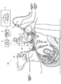
3次元画像を用いる手術支援システム101について説明する。図1は、手術支援システム101の概略構成である。
<First embodiment>
-Surgery support system configuration-
A
手術支援システム101は、格納式カメラ17a,17bとマーカ19a,19bを有する鉗子用トロカール1a,1b(詳細後述)と、腹腔鏡用トロカール3と、鉗子4a,4bと、マーカ19dを有する腹腔鏡5と、格納式カメラ17a,17bから得られた画像と腹腔鏡5から得られた画像を入力し、これらの画像を合成処理し3次元画像を作成する画像処理装置6と、画像処理装置6により作成された3次元画像を出力する3次元モニタ7と、光学センサ9とを備えている。
The surgical
鉗子4a,4bは、手術器具の一種であり、血管や臓器等を、掴んだり、抑えたり、引っ張ったり、切断したりするのに用いられる。一般的に鋏形状をしており、持手部の回動により、支点を介して先端部が作動する。持手部を閉状態にし、鉗子用トロカール1a,1bに挿通させる。なお、腹腔鏡下手術において、複数の鉗子を用いることが一般的であるが、本システムにおいて、鉗子および鉗子用トロカールは少なくとも1以上あればよい。
The
腹腔鏡5は、内視鏡器具の一種であり、カメラと光源を有している。腹腔鏡5は腹腔鏡用トロカール3を挿通して体内に挿入される。マーカ19dは、腹腔鏡5の体内に挿入されない位置に設けられている。
The laparoscope 5 is a kind of endoscopic instrument, and has a camera and a light source. The laparoscope 5 is inserted into the body through the
光学センサ9は、マーカ19a,19b,19dの3次元位置を計測し、計測結果を画像処理装置6に出力する。なお、本実施形態において、光学センサ9はマーカの白と黒を可視光線として認識するものであるが、赤外線を発信し、マーカで反射した赤外線を受信してもよい。光学センサに限定されず、3次元位置を計測できれば磁気センサでもよい。
The
〜トロカール構成〜
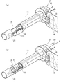
格納式カメラを有するトロカールの構成について説明する。図2は、格納式カメラを有するトロカールの斜視図である。図2(a)と図2(b)とは、視点が異なる。
-Trocar configuration-
A configuration of a trocar having a retractable camera will be described. FIG. 2 is a perspective view of a trocar having a retractable camera. FIG. 2A and FIG. 2B have different viewpoints.
トロカール1は、パイプ部11とヘッド部12から構成される。パイプ部11は、その大部分が腹壁の孔に挿入される。ヘッド部12はパイプ部11の上部に連続して設けられる。ヘッド部12は中空であり、その上部から鉗子が挿入可能になっている。また、詳細は省略するが、ヘッド部12は鉗子の挿抜時に空気の漏れを防止する密封機構と腹腔内に空気を送り込む送気機構とを備える。
The trocar 1 includes a
パイプ部11の確実に体内に挿入される位置に開口部13が設けられている。パイプ部の軸方向であって、かつ、開口部13一端部に沿って、シャフト14が配置される。パイプ部11内壁には複数の軸受15が固定されており、軸受15はシャフト14を回動可能に固定している。シャフト14端部はトロカール外に延長している。シャフト14端部には、切替つまみ16が設けられている。切替つまみ16は、格納位置と展開位置に切替可能であり、各位置で固定される。
An
シャフト14には開口部13に対応する位置に、カメラ17が一体として剛接合されている。カメラ17にはケーブル18が接続されており、ケーブル18はトロカール1内を挿通して、外部の画像処理装置6と接続している。
A
パイプ部11を腹壁の孔に挿入する際は、切替つまみ16を格納位置に固定にし、シャフト14を介してカメラ17を格納位置とする。これにより、カメラ17が障害となることなく、パイプ部11を腹壁の孔に挿入できる。パイプ部11挿入後、切替つまみ16を展開位置に固定にし、シャフト14を介してカメラ17を展開位置とする。この状態で撮影をおこない、手術後パイプ部11を抜き取る際は、切替つまみ16を再び格納位置に固定にし、シャフト14を介してカメラ17を格納位置とする。これにより、カメラ17が障害となることなく、パイプ部11を腹壁より抜き取ることができる。
When inserting the
なお、ケーブル18をシャフト14に沿って配置するか、シャフト14を中空にし、シャフト14内にケーブル18を配置すれば、鉗子挿入時にケーブル18を切断する危険性が無くなるため、更に好ましい。
It is more preferable to arrange the
マーカ19は、ヘッド部12に設けられる。本実施形態においては、一例として白と黒からなるチェッカーフラッグ模様を示しているが、光学センサ9がマーカとして認識できれば、これに限定されない。
The
〜トロカール変形例〜
格納式カメラ17とマーカ19を有していれば、上記構成に限定されない。図3は、変形例にかかるトロカール2の斜視図である。図3(a)は、カメラ17を展開位置に展開した状態図であり、図3(b)は、カメラ17を格納位置に格納した状態図である。図2と共通の構成には同じ符号を付している。トロカール2はパイプ部11とヘッド部12を有する。パイプ部11の体内に挿入される位置に開口部13が設けられる。パイプ部軸方向の開口部一端部に回動可能なヒンジ機構21が設けられており、ヒンジ機構21を介してカメラ17はパイプ部材11に連結される。ヒンジ機構21にはねじりバネ22が設けられており、通常、ねじりバネ22の弾性力はカメラ17を展開するように作用する。一方、カメラ17にはトロカール外まで延長している引張ケーブル23が連結されており、引張ケーブル23を引くと、ねじりバネ22の弾性力に対抗して、カメラ17が開口部13に格納される。カメラ17にはケーブル18が接続されている。
~ Trocar modification ~
If it has the
パイプ部11を腹壁の孔に挿入する際は、引張ケーブル23を引きカメラ17を格納位置とし、パイプ部11挿入後、引張ケーブル23の引張を解除し、カメラ17を展開位置とする。この状態で撮影をおこない、手術後パイプ部11を抜き取る際は、引張ケーブル23を引きカメラ17を再び格納位置とする。
When the
なお、鉗子4の挿入または引き抜く際の引張ケーブル23を切断する危険性を低減するように、ケーブル23はガイドにより保護されている。
The
マーカ19は、ヘッド部12に設けられる。なお、図示裏面のチェッカーフラッグ模様を便宜のため点線で表示している。
The
〜3次元形状計測〜
図4は、3次元形状計測の基本原理について説明する概念図である。2次元形状計測と3次元形状計測との一番の違いは、奥行きの推定である。
~ 3D shape measurement ~
FIG. 4 is a conceptual diagram illustrating the basic principle of three-dimensional shape measurement. The primary difference between 2D shape measurement and 3D shape measurement is depth estimation.
2つのカメラと対象ポイントとが形成する三角形において、2つのカメラ間の距離Lと、カメラ間基線と一のカメラ視線がなす角度αと、カメラ間基線と他のカメラ視線がなす角度βに基づいて、奥行きDを推定できる。なお、カメラ数を増やすことにより、より多くの三角形が形成されるため、推定精度が向上する。 In a triangle formed by two cameras and a target point, based on a distance L between the two cameras, an angle α formed by the camera-to-camera baseline and one camera line of sight, and an angle β formed by the camera-to-camera baseline and another camera line-of-sight Thus, the depth D can be estimated. In addition, since more triangles are formed by increasing the number of cameras, the estimation accuracy is improved.
本実施形態のトロカール1にはマーカ19が固定されている。一方、カメラ17は展開位置に固定されている。すなわち、マーカ19とカメラ17の位置関係は不変である。これにより、画像処理装置6はマーカ19a,19bの3次元位置に基づいてカメラ17a,17bの3次元位置を推定できる。同様に、マーカ19dの3次元位置に基づいて腹腔鏡5のカメラの3次元位置を推定できる。すなわち、カメラ間距離を推定できる。
A
さらに、対象ポイントごとに、角度α,βを測定し、上記基本原理に基づき、対象ポイントの奥行き位置を推定できる。対象ポイントを移動し、奥行き位置推定を繰り返すことにより、腹腔内の3次元形状を計測できる。 Furthermore, the angles α and β are measured for each target point, and the depth position of the target point can be estimated based on the basic principle. The three-dimensional shape in the abdominal cavity can be measured by moving the target point and repeating the depth position estimation.
〜システム全体の効果〜
手術支援システム101を用いた腹腔鏡下手術は、一般的な腹腔鏡下手術を基礎とするものであり、手術方式の大きな変更がないため、術者はこれまでの手術に関する知識と経験をそのまま生かすことができる。
~ Effect of the whole system ~
Laparoscopic surgery using the
また、手術支援システム101は、改良したトロカールを用いた簡素な構成であり、既存の手術支援システムを簡単な改良で再利用することができる。
Further, the
ところで、従来の一般的な腹腔鏡下手術では、腹腔鏡から得られる映像のみを頼りに行われるため視野が狭かった。特に、奥行きに係る画像情報が得られなかった。精度の良い3時次元形状計測をすべく別のカメラを挿入するように新たに腹壁に孔をあけると、低侵襲性を損なう。 By the way, in the conventional general laparoscopic surgery, the field of view is narrow because it is performed only by using images obtained from the laparoscope. In particular, image information relating to depth could not be obtained. If a new hole is made in the abdominal wall so that another camera is inserted for accurate three-dimensional shape measurement, the minimally invasiveness is impaired.
本実施形態では、格納式カメラ17a,17bを有するトロカール1a,1bを用いることにより、腹腔内に複数のカメラを挿入することができる。このとき、鉗子用トロカールを用いるため、新たに腹壁に孔をあける必要はない。これにより、低侵襲性を維持しながら、3次元形状を計測できる。
In this embodiment, a plurality of cameras can be inserted into the abdominal cavity by using the
更に、画像処理装置6が3次元画像を作成し、3次元モニタ7に3次元画像を出力する。術者は3次元モニタ7を見ることで、奥行き情報を含む広い視野を得ることができる。これにより、術者の負担を軽減できる。
Further, the
〜精度向上に係る効果〜
(1)3次元形状計測の基本原理について説明したように、奥行きを推定するには、カメラ17a,17bの3次元位置を推定する必要がある。しかしながら、カメラ17a,17bは腹腔内にあるため直接、位置を計測できない。さらに、鉗子4a,4bの動きに伴って、トロカール1a,1bの角度が変わり、その結果、カメラ17a,17bが微動する。そのため、3次元位置の推定は困難であるという課題がある。図5はカメラ位置推定の困難性に係る課題を説明する概念図である。
~ Effects on accuracy improvement ~
(1) As described for the basic principle of three-dimensional shape measurement, in order to estimate the depth, it is necessary to estimate the three-dimensional positions of the
そこで、発明者は、トロカール1a,1bの微動に連動してカメラ17a,17bが微動することに着目し、トロカール1a,1bのヘッド部12にマーカ19a,19bを設けた。すなわち、マーカ19a,19bと展開位置のカメラ17a,17bの位置関係は不変である。一方、マーカ19a,19bの3次元位置は光学センサ9により精度よく検出できる。したがって、マーカ19a,19bの3次元位置に基づきカメラ17a,17bの3次元位置を精度よく推定できる。
Therefore, the inventor has provided the
なお、腹腔鏡5のカメラの動きは、トロカール3の微動と連動しないため、マーカ19dは腹腔鏡5に設けられている。これにより、腹腔鏡5のカメラの3次元位置を精度よく推定できる。
In addition, since the movement of the camera of the laparoscope 5 does not interlock with the fine movement of the
カメラの三次元位置を精度よく推定し、カメラ間距離を精度よく推定できる結果、奥行きを精度よく推定でき、腹腔内の3次元形状計測を精度よくおこなうことができる。 As a result of accurately estimating the three-dimensional position of the camera and accurately estimating the distance between the cameras, it is possible to accurately estimate the depth and to accurately measure the three-dimensional shape in the abdominal cavity.
(2)3次元形状計測の基本原理について説明したように、カメラ数を増やすことにより、奥行き推定の精度が向上する。一般に、腹腔鏡下手術において、複数(例えば2〜5程度)の鉗子が用いられる。その結果、腹腔鏡5以外にも、複数のカメラ17が腹腔内に挿入される。これにより、奥行きを精度よく推定でき、腹腔内の3次元形状計測を精度よくおこなうことができる。
(2) As described for the basic principle of three-dimensional shape measurement, the accuracy of depth estimation is improved by increasing the number of cameras. In general, a plurality of forceps (for example, about 2 to 5) are used in laparoscopic surgery. As a result, a plurality of
(3)ところで、立体内視鏡を用いても、腹腔内の3次元形状計測は可能である。しかしながら、立体内視鏡は、カメラ間の距離が非常に狭く、三角形が極端に細長くなり、その結果、奥行き推定の精度が良くない。 (3) By the way, even if a three-dimensional endoscope is used, three-dimensional shape measurement in the abdominal cavity is possible. However, in the stereoscopic endoscope, the distance between the cameras is very narrow, and the triangle is extremely elongated. As a result, the accuracy of depth estimation is not good.
図6は、カメラ間距離と奥行き推定精度の関係を示す概念図である。図6(a)は、カメラ間距離が非常に狭いケース、図6(b)は、カメラ間距離が広いケースを示している。 FIG. 6 is a conceptual diagram showing the relationship between the inter-camera distance and the depth estimation accuracy. 6A shows a case where the distance between the cameras is very small, and FIG. 6B shows a case where the distance between the cameras is wide.
図6(a)において、カメラ間距離を非常に狭いL1とし、実際の奥行きをDとする。カメラ視線に誤差があった場合の推定奥行きはD1となる。図6(b)において、カメラ間距離を充分広いL2とし、実際の奥行きをD(図6(a)と同じ)とする。カメラ視線に誤差(図6(a)と同レベル)があった場合の推定奥行きはD2となる。 In FIG. 6A, the distance between the cameras is L1, and the actual depth is D. The estimated depth when there is an error in the camera line of sight is D1. In FIG. 6B, the distance between the cameras is set to be sufficiently large L2, and the actual depth is set to D (same as FIG. 6A). The estimated depth when there is an error in the camera line of sight (the same level as in FIG. 6A) is D2.
推定奥行きD1は大きな誤差を有するのに対し、推定奥行きD2の誤差は小さい。 The estimated depth D1 has a large error, whereas the estimated depth D2 has a small error.
一般に、腹腔鏡下手術において、複数(例えば2〜5程度)の鉗子用のトロカール1が腹壁にほぼ均等に配置される。言い換えると、トロカール1が密集して配置される可能性はほぼない。これにより、充分広いカメラ間距離を確保でき、奥行きを精度よく推定でき、腹腔内の3次元形状計測を精度よくおこなうことができる。 In general, in laparoscopic surgery, a plurality (for example, about 2 to 5) of forceps trocars 1 are arranged substantially evenly on the abdominal wall. In other words, there is almost no possibility that the trocars 1 are densely arranged. As a result, a sufficiently wide inter-camera distance can be secured, the depth can be estimated with high accuracy, and the three-dimensional shape measurement within the abdominal cavity can be performed with high accuracy.
<第2実施例>
図7は手術支援システム102の概略構成図である。手術支援システム102は、格納式カメラ17a,17b,17cとマーカ19a,19b,19cを有する鉗子用トロカール1a,1b,1cと、鉗子4a,4b,4cと、マーカ19a,19b,19cの3次元位置に基づきカメラ17a,17b,17cの3次元位置を推定し、カメラから得られた画像を合成し、3次元画像を作成する画像処理装置6と、画像処理装置6により作成された3次元画像を出力する3次元モニタ7とを備えている。
<Second embodiment>
FIG. 7 is a schematic configuration diagram of the
すなわち、実施例1の手術支援システム101における腹腔鏡用トロカール3と腹腔鏡5とマーカ19dとがなく、格納式カメラ17cを有する鉗子用トロカール1cと、鉗子4cとマーカ19cとが追加されている。
That is, there is no
なお、腹腔鏡下手術において、複数の鉗子を用いることが一般的であるが、本システムにおいて、鉗子および鉗子用トロカールは少なくとも2以上あればよい。 In general, a plurality of forceps are used in laparoscopic surgery. However, in this system, at least two forceps and trocars for forceps may be used.
実施例1の様に腹腔鏡5を用いる場合、術者が腹腔鏡5の向きを操作し切断箇所などを探す必要があるのに対し、格納式カメラ17は、鉗子4aの先端部を確実に撮影するため、切断箇所など重要な画像を確実に得ることができる。したがって、格納式カメラ17の性能が高いこと前提に、腹腔鏡5より高品質な画像を確実に得ることができる。
When the laparoscope 5 is used as in the first embodiment, the operator needs to operate the direction of the laparoscope 5 to search for a cutting portion and the like, whereas the
一方、腹腔鏡用トロカール3と腹腔鏡5が不要となることで、これらのための孔を腹壁にあける必要はなく、低侵襲性が向上する。
On the other hand, since the
ただし、腹腔鏡5の光源に代替する光源をトロカール1(またはカメラ17)に設ける必要がある。 However, it is necessary to provide the trocar 1 (or the camera 17) with a light source that replaces the light source of the laparoscope 5.
<第3実施例>
実施例3は実施例1・2の変形例である。実施例1・2では、術者はモニタ7を見ながら鉗子4や腹腔鏡5を操作し手術を行うが、術者の視線と実際の術野とに方向の不一致が生じ、術者に違和感を与え、負担になる。特に、開腹手術の経験豊富な術者は、腹腔鏡下手術に慣れないこともある。
<Third embodiment>
The third embodiment is a modification of the first and second embodiments. In the first and second embodiments, the surgeon operates the forceps 4 and the laparoscope 5 while looking at the
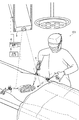
図8は手術支援システム103の概略構成図である。実施例1・2と共通する構成は適宜省略している。手術支援システム103は、3次元モニタ7に替えて、3次元プロジェクタ8を備えている。3次元プロジェクタ8は、手術台の上方に設けられ、画像処理装置6により作成された3次元画像を患者の腹部に直接投影する。
FIG. 8 is a schematic configuration diagram of the
これにより、術者の視線と術野の方向は一致し、開腹手術と同様な現実感を表現できる。すなわち、術者の負担を軽減できる。 As a result, the operator's line of sight matches the direction of the surgical field, and a realistic feeling similar to that in open surgery can be expressed. That is, the burden on the operator can be reduced.
1 トロカール
2 トロカール(変形例)
3 トロカール(腹腔鏡用)
4 鉗子
5 腹腔鏡
6 画像処理装置
7 3次元モニタ
8 3次元プロジェクタ
9 光学センサ
11 パイプ部
12 ヘッド部
13 開口部
14 シャフト
15 軸受
16切替つまみ
17 カメラ
18 ケーブル
19 マーカ
21 ヒンジ機構
22 ねじりバネ
23 引張ケーブル
1 Trocar 2 Trocar (Modification)
3 Trocar (for laparoscope)
DESCRIPTION OF SYMBOLS 4 Forceps 5
Claims (5)
前記パイプ部の体内に挿入される位置に設けられる開口部と、
前記開口部を通して、パイプ部内に格納される格納位置とパイプ部外に撮影可能に展開される展開位置とに切替可能に配置されるカメラと、
前記ヘッド部に設けられる位置マーカと、
を有することを特徴とするトロカール。 A trocar having a pipe part for inserting a medical device into the body and a head part provided continuously on the upper part of the pipe part, and provided on the abdominal wall via the pipe part,
An opening provided at a position to be inserted into the body of the pipe portion;
A camera disposed so as to be switchable between a storage position stored in the pipe part and a development position developed so as to be photographed outside the pipe part through the opening;
A position marker provided on the head part;
A trocar characterized by comprising:
ことを特徴とする請求項1記載のトロカール。 The trocar according to claim 1, wherein the position marker is an optical marker.
格納位置と展開位置とに切替可能な格納式カメラと位置マーカとを有する鉗子用トロカールと、
前記腹腔鏡の位置マーカおよび前記鉗子用トロカールの位置マーカの位置を検出する位置検出センサと、
前記位置マーカの位置に基づき前記カメラの位置を推定し、該カメラの位置に基づき前記カメラから得られた画像を合成し、3次元画像を作成する画像処理装置と
を備えることを特徴とする手術支援システム。 A laparoscope having a camera and a position marker;
A forceps trocar having a retractable camera switchable between a retracted position and a deployed position and a position marker;
A position detection sensor for detecting a position marker of the laparoscope and a position marker of the forceps trocar;
An operation comprising: an image processing device that estimates a position of the camera based on a position of the position marker, synthesizes an image obtained from the camera based on the position of the camera, and creates a three-dimensional image. Support system.
前記鉗子用トロカールの位置マーカの位置を検出する位置センサと、
前記位置マーカの位置に基づき前記カメラの位置を推定し、該カメラの位置に基づき前記カメラから得られた画像を合成し、3次元画像を作成する画像処理装置と、
を備えることを特徴とする手術支援システム。 A plurality of forceps trocars having a retractable camera switchable between a retracted position and a deployed position and a position marker;
A position sensor for detecting the position of the position marker of the forceps trocar;
An image processing device that estimates the position of the camera based on the position of the position marker, synthesizes images obtained from the camera based on the position of the camera, and creates a three-dimensional image;
An operation support system comprising:
をさらに備えることを特徴とする請求項3および4記載の手術支援システム。 5. The surgery support system according to claim 3, further comprising a three-dimensional projector provided above the operating table and projecting the three-dimensional image onto the abdomen of the patient.
Priority Applications (3)
| Application Number | Priority Date | Filing Date | Title |
|---|---|---|---|
| JP2013002338A JP2014132980A (en) | 2013-01-10 | 2013-01-10 | Trocar and surgery support system |
| KR1020130098799A KR20140090927A (en) | 2013-01-10 | 2013-08-21 | Trocar, and surgery assistance system |
| US13/974,780 US20140194732A1 (en) | 2013-01-10 | 2013-08-23 | Trocar, and surgery assistance system |
Applications Claiming Priority (1)
| Application Number | Priority Date | Filing Date | Title |
|---|---|---|---|
| JP2013002338A JP2014132980A (en) | 2013-01-10 | 2013-01-10 | Trocar and surgery support system |
Publications (2)
| Publication Number | Publication Date |
|---|---|
| JP2014132980A true JP2014132980A (en) | 2014-07-24 |
| JP2014132980A5 JP2014132980A5 (en) | 2016-03-10 |
Family
ID=51061492
Family Applications (1)
| Application Number | Title | Priority Date | Filing Date |
|---|---|---|---|
| JP2013002338A Pending JP2014132980A (en) | 2013-01-10 | 2013-01-10 | Trocar and surgery support system |
Country Status (3)
| Country | Link |
|---|---|
| US (1) | US20140194732A1 (en) |
| JP (1) | JP2014132980A (en) |
| KR (1) | KR20140090927A (en) |
Cited By (5)
| Publication number | Priority date | Publication date | Assignee | Title |
|---|---|---|---|---|
| JP2016131866A (en) * | 2015-01-18 | 2016-07-25 | 鈴木 秀幸 | Ultrasonic distance measurement instrument for endoscopic surgery |
| JP2017512609A (en) * | 2014-03-13 | 2017-05-25 | ナビゲート サージカル テクノロジーズ インク | System and method for real-time tracking and modeling of a surgical site |
| WO2018003140A1 (en) * | 2016-06-27 | 2018-01-04 | 株式会社A-Traction | Surgical assistance device, method and program for controlling same, and surgical assistance system |
| CN110709027A (en) * | 2017-06-08 | 2020-01-17 | 美多斯国际有限公司 | User interface system for sterile field and other work environments |
| WO2023003389A1 (en) * | 2021-07-21 | 2023-01-26 | (주)휴톰 | Apparatus and method for determining insertion position of trocar on three-dimensional virtual pneumoperitoneum model of patient |
Families Citing this family (9)
| Publication number | Priority date | Publication date | Assignee | Title |
|---|---|---|---|---|
| US10052068B2 (en) * | 2014-07-15 | 2018-08-21 | Synaptive Medical (Barbados), Inc. | Tip tracking apparatus for medical procedures |
| JP5975504B2 (en) * | 2014-07-24 | 2016-08-23 | アドバンストヘルスケア株式会社 | Trocar, port, surgery support system |
| WO2016026511A1 (en) * | 2014-08-18 | 2016-02-25 | G-coder Systems AB | Arrangement for minimal invasive intervention |
| EP3367950A4 (en) * | 2015-10-28 | 2019-10-02 | Endochoice, Inc. | Device and method for tracking the position of an endoscope within a patient's body |
| EP3387982B1 (en) * | 2015-12-07 | 2020-09-23 | Kyocera Corporation | Trocar |
| WO2018109749A1 (en) * | 2016-12-18 | 2018-06-21 | Medical And Education Consulting Management Group Inc. | Apparatus with imaging functionality |
| US20230100698A1 (en) * | 2021-09-29 | 2023-03-30 | Cilag Gmbh International | Methods for Controlling Cooperative Surgical Instruments |
| US11937798B2 (en) | 2021-09-29 | 2024-03-26 | Cilag Gmbh International | Surgical systems with port devices for instrument control |
| CN115414116B (en) * | 2022-11-07 | 2023-03-24 | 中南大学 | Simulation positioning selection system for optimal site of laparoscope stab card |
Citations (9)
| Publication number | Priority date | Publication date | Assignee | Title |
|---|---|---|---|---|
| JPH05305073A (en) * | 1992-05-01 | 1993-11-19 | Olympus Optical Co Ltd | Position detection display device for insertion tool |
| JP2005046200A (en) * | 2003-07-29 | 2005-02-24 | Olympus Corp | Endoscopic operation system |
| JP2005111081A (en) * | 2003-10-09 | 2005-04-28 | Olympus Corp | Endoscopic image display processor |
| JP2006288869A (en) * | 2005-04-13 | 2006-10-26 | Hitachi Medical Corp | Display device of endoscopic image |
| JP2008006227A (en) * | 2006-06-30 | 2008-01-17 | Jichi Medical Univ | Laparoscopic port |
| JP2010200894A (en) * | 2009-03-02 | 2010-09-16 | Tadashi Ukimura | Surgery support system and surgical robot system |
| US20120108955A1 (en) * | 2006-08-02 | 2012-05-03 | Inneroptic Technology Inc. | System and method of providing real-time dynamic imagery of a medical procedure site using multiple modalities |
| US20120143002A1 (en) * | 2008-01-10 | 2012-06-07 | Ernest Aranyi | Apparatus for Endoscopic Procedures |
| JP2012200597A (en) * | 2011-03-24 | 2012-10-22 | Tyco Healthcare Group Lp | Swing out surgery camera |
Family Cites Families (8)
| Publication number | Priority date | Publication date | Assignee | Title |
|---|---|---|---|---|
| US8565860B2 (en) * | 2000-08-21 | 2013-10-22 | Biosensors International Group, Ltd. | Radioactive emission detector equipped with a position tracking system |
| AU2006238292B2 (en) * | 2005-03-31 | 2010-04-15 | Olympus Medical Systems Corp. | Surgery assisting apparatus and treatment assisting apparatus |
| US7824414B2 (en) * | 2005-07-22 | 2010-11-02 | Kensey Nash Corporation | System and devices for the repair of a vertebral disc defect |
| SG132553A1 (en) * | 2005-11-28 | 2007-06-28 | Pang Ah San | A device for laparoscopic or thoracoscopic surgery |
| JP4980625B2 (en) * | 2006-02-21 | 2012-07-18 | 富士フイルム株式会社 | Body cavity observation device |
| US20100210902A1 (en) * | 2006-05-04 | 2010-08-19 | Nassir Navab | Virtual Penetrating Mirror Device and Method for Visualizing Virtual Objects in Endoscopic Applications |
| US7841980B2 (en) * | 2006-05-11 | 2010-11-30 | Olympus Medical Systems Corp. | Treatment system, trocar, treatment method and calibration method |
| US20110046637A1 (en) * | 2008-01-14 | 2011-02-24 | The University Of Western Ontario | Sensorized medical instrument |
-
2013
- 2013-01-10 JP JP2013002338A patent/JP2014132980A/en active Pending
- 2013-08-21 KR KR1020130098799A patent/KR20140090927A/en not_active Application Discontinuation
- 2013-08-23 US US13/974,780 patent/US20140194732A1/en not_active Abandoned
Patent Citations (9)
| Publication number | Priority date | Publication date | Assignee | Title |
|---|---|---|---|---|
| JPH05305073A (en) * | 1992-05-01 | 1993-11-19 | Olympus Optical Co Ltd | Position detection display device for insertion tool |
| JP2005046200A (en) * | 2003-07-29 | 2005-02-24 | Olympus Corp | Endoscopic operation system |
| JP2005111081A (en) * | 2003-10-09 | 2005-04-28 | Olympus Corp | Endoscopic image display processor |
| JP2006288869A (en) * | 2005-04-13 | 2006-10-26 | Hitachi Medical Corp | Display device of endoscopic image |
| JP2008006227A (en) * | 2006-06-30 | 2008-01-17 | Jichi Medical Univ | Laparoscopic port |
| US20120108955A1 (en) * | 2006-08-02 | 2012-05-03 | Inneroptic Technology Inc. | System and method of providing real-time dynamic imagery of a medical procedure site using multiple modalities |
| US20120143002A1 (en) * | 2008-01-10 | 2012-06-07 | Ernest Aranyi | Apparatus for Endoscopic Procedures |
| JP2010200894A (en) * | 2009-03-02 | 2010-09-16 | Tadashi Ukimura | Surgery support system and surgical robot system |
| JP2012200597A (en) * | 2011-03-24 | 2012-10-22 | Tyco Healthcare Group Lp | Swing out surgery camera |
Non-Patent Citations (1)
| Title |
|---|
| TAKUYA OKUBO,外3名: ""Abdominal view expansion by retractable camera"", JOURNAL OF SIGNAL PROCESSING, vol. 第15巻,第4号, JPN6014022548, July 2011 (2011-07-01), pages 311 - 314, ISSN: 0003503296 * |
Cited By (8)
| Publication number | Priority date | Publication date | Assignee | Title |
|---|---|---|---|---|
| JP2017512609A (en) * | 2014-03-13 | 2017-05-25 | ナビゲート サージカル テクノロジーズ インク | System and method for real-time tracking and modeling of a surgical site |
| JP2016131866A (en) * | 2015-01-18 | 2016-07-25 | 鈴木 秀幸 | Ultrasonic distance measurement instrument for endoscopic surgery |
| WO2018003140A1 (en) * | 2016-06-27 | 2018-01-04 | 株式会社A-Traction | Surgical assistance device, method and program for controlling same, and surgical assistance system |
| JPWO2018003140A1 (en) * | 2016-06-27 | 2019-05-16 | 株式会社A−Traction | Surgical support device, control method and program thereof, and surgical support system |
| CN110709027A (en) * | 2017-06-08 | 2020-01-17 | 美多斯国际有限公司 | User interface system for sterile field and other work environments |
| JP2020523102A (en) * | 2017-06-08 | 2020-08-06 | メドス・インターナショナル・エスエイアールエルMedos International SARL | User interface system for sterilization fields and other work environments |
| JP7267209B2 (en) | 2017-06-08 | 2023-05-01 | メドス・インターナショナル・エスエイアールエル | User interface system for sterile fields and other work environments |
| WO2023003389A1 (en) * | 2021-07-21 | 2023-01-26 | (주)휴톰 | Apparatus and method for determining insertion position of trocar on three-dimensional virtual pneumoperitoneum model of patient |
Also Published As
| Publication number | Publication date |
|---|---|
| KR20140090927A (en) | 2014-07-18 |
| US20140194732A1 (en) | 2014-07-10 |
Similar Documents
| Publication | Publication Date | Title |
|---|---|---|
| JP2014132980A (en) | Trocar and surgery support system | |
| US10835344B2 (en) | Display of preoperative and intraoperative images | |
| JP5975500B2 (en) | Trocar, port and surgical support system | |
| US9289267B2 (en) | Method and apparatus for minimally invasive surgery using endoscopes | |
| JP6129344B2 (en) | Endoscopy, especially for minimally invasive surgery | |
| JP5975504B2 (en) | Trocar, port, surgery support system | |
| JP5380348B2 (en) | System, method, apparatus, and program for supporting endoscopic observation | |
| US8414476B2 (en) | Method for using variable direction of view endoscopy in conjunction with image guided surgical systems | |
| EP2641561A1 (en) | System and method for determining camera angles by using virtual planes derived from actual images | |
| ES2815800T3 (en) | Navigation, tracking and guidance system for the positioning of surgical instruments within the body of a patient | |
| US20130281821A1 (en) | Intraoperative camera calibration for endoscopic surgery | |
| US20050054895A1 (en) | Method for using variable direction of view endoscopy in conjunction with image guided surgical systems | |
| US11266294B2 (en) | Image processing device, endoscopic surgery system, and image processing method | |
| ES2715650T3 (en) | Multiple vision imaging system for laparoscopic surgery | |
| JP2014132979A (en) | Trocar and surgery support system | |
| JP2017508529A (en) | Endoscope measurement system and method | |
| US20160360954A1 (en) | Imagery System | |
| WO2007115825A1 (en) | Registration-free augmentation device and method | |
| JP6932135B2 (en) | Computational device for superimposing laparoscopic images and ultrasonic images | |
| JP2012165838A (en) | Endoscope insertion support device | |
| WO2008004222A2 (en) | Computer image-aided method and system for guiding instruments through hollow cavities | |
| WO2015091226A1 (en) | Laparoscopic view extended with x-ray vision | |
| JP2017205343A (en) | Endoscope device and method for operating endoscope device | |
| KR20200132174A (en) | AR colonoscopy system and method for monitoring by using the same | |
| JP2015136460A (en) | trocar and port |
Legal Events
| Date | Code | Title | Description |
|---|---|---|---|
| A621 | Written request for application examination |
Free format text: JAPANESE INTERMEDIATE CODE: A621 Effective date: 20151225 |
|
| A711 | Notification of change in applicant |
Free format text: JAPANESE INTERMEDIATE CODE: A711 Effective date: 20151225 |
|
| A521 | Request for written amendment filed |
Free format text: JAPANESE INTERMEDIATE CODE: A821 Effective date: 20151225 |
|
| A521 | Request for written amendment filed |
Free format text: JAPANESE INTERMEDIATE CODE: A523 Effective date: 20160121 |
|
| A131 | Notification of reasons for refusal |
Free format text: JAPANESE INTERMEDIATE CODE: A131 Effective date: 20160831 |
|
| A977 | Report on retrieval |
Free format text: JAPANESE INTERMEDIATE CODE: A971007 Effective date: 20160830 |
|
| A521 | Request for written amendment filed |
Free format text: JAPANESE INTERMEDIATE CODE: A523 Effective date: 20161012 |
|
| A131 | Notification of reasons for refusal |
Free format text: JAPANESE INTERMEDIATE CODE: A131 Effective date: 20170222 |
|
| A521 | Request for written amendment filed |
Free format text: JAPANESE INTERMEDIATE CODE: A523 Effective date: 20170421 |
|
| A02 | Decision of refusal |
Free format text: JAPANESE INTERMEDIATE CODE: A02 Effective date: 20170614 |