EP3169239B1 - Differenzielle phasenkontrastbildgebungsvorrichtung mit einem oder mehreren beweglichen gittern - Google Patents
Differenzielle phasenkontrastbildgebungsvorrichtung mit einem oder mehreren beweglichen gittern Download PDFInfo
- Publication number
- EP3169239B1 EP3169239B1 EP15734376.5A EP15734376A EP3169239B1 EP 3169239 B1 EP3169239 B1 EP 3169239B1 EP 15734376 A EP15734376 A EP 15734376A EP 3169239 B1 EP3169239 B1 EP 3169239B1
- Authority
- EP
- European Patent Office
- Prior art keywords
- grating
- segment
- ray
- imaging device
- ray beam
- Prior art date
- Legal status (The legal status is an assumption and is not a legal conclusion. Google has not performed a legal analysis and makes no representation as to the accuracy of the status listed.)
- Not-in-force
Links
Images
Classifications
-
- A—HUMAN NECESSITIES
- A61—MEDICAL OR VETERINARY SCIENCE; HYGIENE
- A61B—DIAGNOSIS; SURGERY; IDENTIFICATION
- A61B6/00—Apparatus for radiation diagnosis, e.g. combined with radiation therapy equipment
- A61B6/04—Positioning of patients; Tiltable beds or the like
- A61B6/0407—Supports, e.g. tables or beds, for the body or parts of the body
- A61B6/0414—Supports, e.g. tables or beds, for the body or parts of the body with compression means
-
- A—HUMAN NECESSITIES
- A61—MEDICAL OR VETERINARY SCIENCE; HYGIENE
- A61B—DIAGNOSIS; SURGERY; IDENTIFICATION
- A61B6/00—Apparatus for radiation diagnosis, e.g. combined with radiation therapy equipment
- A61B6/06—Diaphragms
-
- A—HUMAN NECESSITIES
- A61—MEDICAL OR VETERINARY SCIENCE; HYGIENE
- A61B—DIAGNOSIS; SURGERY; IDENTIFICATION
- A61B6/00—Apparatus for radiation diagnosis, e.g. combined with radiation therapy equipment
- A61B6/42—Apparatus for radiation diagnosis, e.g. combined with radiation therapy equipment with arrangements for detecting radiation specially adapted for radiation diagnosis
- A61B6/4291—Apparatus for radiation diagnosis, e.g. combined with radiation therapy equipment with arrangements for detecting radiation specially adapted for radiation diagnosis the detector being combined with a grid or grating
-
- A—HUMAN NECESSITIES
- A61—MEDICAL OR VETERINARY SCIENCE; HYGIENE
- A61B—DIAGNOSIS; SURGERY; IDENTIFICATION
- A61B6/00—Apparatus for radiation diagnosis, e.g. combined with radiation therapy equipment
- A61B6/44—Constructional features of apparatus for radiation diagnosis
- A61B6/4429—Constructional features of apparatus for radiation diagnosis related to the mounting of source units and detector units
- A61B6/4435—Constructional features of apparatus for radiation diagnosis related to the mounting of source units and detector units the source unit and the detector unit being coupled by a rigid structure
-
- A—HUMAN NECESSITIES
- A61—MEDICAL OR VETERINARY SCIENCE; HYGIENE
- A61B—DIAGNOSIS; SURGERY; IDENTIFICATION
- A61B6/00—Apparatus for radiation diagnosis, e.g. combined with radiation therapy equipment
- A61B6/48—Diagnostic techniques
- A61B6/484—Diagnostic techniques involving phase contrast X-ray imaging
-
- A—HUMAN NECESSITIES
- A61—MEDICAL OR VETERINARY SCIENCE; HYGIENE
- A61B—DIAGNOSIS; SURGERY; IDENTIFICATION
- A61B6/00—Apparatus for radiation diagnosis, e.g. combined with radiation therapy equipment
- A61B6/54—Control of apparatus or devices for radiation diagnosis
-
- G—PHYSICS
- G01—MEASURING; TESTING
- G01N—INVESTIGATING OR ANALYSING MATERIALS BY DETERMINING THEIR CHEMICAL OR PHYSICAL PROPERTIES
- G01N23/00—Investigating or analysing materials by the use of wave or particle radiation, e.g. X-rays or neutrons, not covered by groups G01N3/00 – G01N17/00, G01N21/00 or G01N22/00
- G01N23/02—Investigating or analysing materials by the use of wave or particle radiation, e.g. X-rays or neutrons, not covered by groups G01N3/00 – G01N17/00, G01N21/00 or G01N22/00 by transmitting the radiation through the material
- G01N23/06—Investigating or analysing materials by the use of wave or particle radiation, e.g. X-rays or neutrons, not covered by groups G01N3/00 – G01N17/00, G01N21/00 or G01N22/00 by transmitting the radiation through the material and measuring the absorption
- G01N23/083—Investigating or analysing materials by the use of wave or particle radiation, e.g. X-rays or neutrons, not covered by groups G01N3/00 – G01N17/00, G01N21/00 or G01N22/00 by transmitting the radiation through the material and measuring the absorption the radiation being X-rays
-
- A—HUMAN NECESSITIES
- A61—MEDICAL OR VETERINARY SCIENCE; HYGIENE
- A61B—DIAGNOSIS; SURGERY; IDENTIFICATION
- A61B6/00—Apparatus for radiation diagnosis, e.g. combined with radiation therapy equipment
- A61B6/40—Apparatus for radiation diagnosis, e.g. combined with radiation therapy equipment with arrangements for generating radiation specially adapted for radiation diagnosis
- A61B6/4035—Apparatus for radiation diagnosis, e.g. combined with radiation therapy equipment with arrangements for generating radiation specially adapted for radiation diagnosis the source being combined with a filter or grating
-
- A—HUMAN NECESSITIES
- A61—MEDICAL OR VETERINARY SCIENCE; HYGIENE
- A61B—DIAGNOSIS; SURGERY; IDENTIFICATION
- A61B6/00—Apparatus for radiation diagnosis, e.g. combined with radiation therapy equipment
- A61B6/42—Apparatus for radiation diagnosis, e.g. combined with radiation therapy equipment with arrangements for detecting radiation specially adapted for radiation diagnosis
- A61B6/4208—Apparatus for radiation diagnosis, e.g. combined with radiation therapy equipment with arrangements for detecting radiation specially adapted for radiation diagnosis characterised by using a particular type of detector
-
- A—HUMAN NECESSITIES
- A61—MEDICAL OR VETERINARY SCIENCE; HYGIENE
- A61B—DIAGNOSIS; SURGERY; IDENTIFICATION
- A61B6/00—Apparatus for radiation diagnosis, e.g. combined with radiation therapy equipment
- A61B6/44—Constructional features of apparatus for radiation diagnosis
- A61B6/4429—Constructional features of apparatus for radiation diagnosis related to the mounting of source units and detector units
-
- A—HUMAN NECESSITIES
- A61—MEDICAL OR VETERINARY SCIENCE; HYGIENE
- A61B—DIAGNOSIS; SURGERY; IDENTIFICATION
- A61B6/00—Apparatus for radiation diagnosis, e.g. combined with radiation therapy equipment
- A61B6/50—Clinical applications
- A61B6/502—Clinical applications involving diagnosis of breast, i.e. mammography
Definitions
- the invention relates to an X-ray imaging device, an X-ray imaging system, an X-ray imaging method, a computer program element for controlling such device and a computer readable medium having stored such computer program element.
- an object to be examined e.g. a patient
- an X-ray generating device When acquiring an X-ray image, an object to be examined, e.g. a patient, is arranged between an X-ray generating device and an X-ray detector.
- X-ray radiation emanating from the X-ray generating device is penetrating the object to be examined, subsequently arriving at the X-ray detector.
- the object to be examined, situated in the path of the X-ray radiation is spatially attenuating the X-ray beam, depending on the specific tissue structure within the object.
- the X-ray detector is subsequently detecting the spatially attenuated X-ray radiation by determining an intensity distribution of the X-ray radiation, which image information is employed for generating, further processing, and subsequently displaying an X-ray image of the object to be examined.
- an object to be examined may provide only minor differences when attenuating the X-ray radiation, resulting in a relatively uniformly attenuated X-ray image having low contrast, thus lacking detail of the imaged inner structure of the object.
- a phase of X-ray radiation penetrating the object may be influenced to a larger extent by the structure of the object.
- phase-contrast imaging at least partly coherent X-ray radiation is employed, e.g., generated by a source grating arranged adjacent to, in the vicinity of an X-ray source, e.g. an X-ray tube.
- Coherent X-rays penetrating the object may allow for subsequent retrieval of phase information.
- phase of a wave may not be measured directly, rather a phase-shift may be required to be converted to an intensity modulation, e.g., by interfering two or more waves.
- a so-called phase grating is employed, arranged between the object to be examined and an X-ray detector.
- an interference pattern generated by only employing a phase grating may be too small to be detectable with a current X-ray detector, due to a lack of spatial resolution of the X-ray detector.
- a further analyzer grating may be employed arranged between the phase grating and the X-ray detector, subsequently providing an interference pattern, which is large enough to be detectable by current X-ray detectors.
- phase stepping is performed.
- one of the source grating, the phase grating, and the analyzer grating is displaced laterally with respect to the other grating and the X-ray detector element by a fraction of its grating pitch, e.g., a fourth, sixth, eighth of the grating pitch, e.g. of the phase grating. If the phase stepping is performed using a particular grating, then the phase stepping shall cover a full period of this particular grating.
- phase stepping is the so-called slit scanning approach.
- the object e.g. a woman's breast, is scanned by a scan arm or gantry movement.
- the redundancy of the data acquisition by means of an arrangement of a number of parallel detector lines can be exploited to eliminate the need for phase-stepping and the gratings need not be moved with respect to each other.
- the phase-acquisition can be implemented in the ordinary scanning motion.
- phase grating in addition the generation of image data deriving from de-coherent X-ray small angle scattering is enabled, the latter type of imaging also being referred to as "dark-field imaging".
- WO 2012/029005 A1 discloses an apparatus for phase-contrast imaging comprising an X-ray source, a first grating element, a second grating element and an X-ray detector element comprising a plurality of detector pixel elements.
- An object to be imagined is arrangeable between the X-ray source and the X-ray detector element.
- the first grating element as well as the second grating element is arrangeable between the X-ray source and the X-ray detector element.
- the X-ray source, the first grating element, the second grating element and the X-ray detector are operatively coupled for acquisition of a phase-contrast image of the object.
- WO 2013/111050 A1 by applicant discloses a phase contrast X-ray imaging apparatus comprising a line detector and grating elements provided with mutually different directions.
- US 2013/202081 A1 by applicant discloses an X-ray image acquisition device comprising a diffraction grating that is movable with respect to the device's detector.
- the diffraction grating is provided with at least two grating structures, which have different grating orientations.
- imaging devices can be still improved, in particular in view of the flexibility and adaptability to different patients and operation conditions.
- an X-ray imaging device comprises an X-ray source arrangement for providing an X-ray beam, at least one grating, and a line detector with a plurality of sensor lines, which sensor lines are each provided by a plurality of sensor elements, and which sensor lines are provided for detecting respective portions of the X-ray beam passing the at least one grating during operation.
- the line detector may comprise several one dimensional sensors forming the several sensor lines.
- the X-ray imaging device is arranged for moving the line detector and an object to be imaged relative to each other, such that in response to the portions of the X-ray beam a number of interference patterns are detectable at respective different relative positions of the line detector and the object for reconstructing an image of the object. This means, the X-ray imaging device, the line detector and/or the object can be moved.
- the at least one grating comprises at least one first segment and at least one second segment arranged adjacent to each other in a direction perpendicular to the direction of the line detector, and to the X-ray beam direction.
- the at least one grating may be placed in front of each sensor line, when seen in the X-ray beam direction.
- the at least one grating may be a phase grating and/or an absorber grating.
- the X-ray imaging device is arranged for moving the line detector and the at least one grating relative to each other between at least a first relative position and a second relative position, such that in the first relative position, a portion of the X-ray beam during operation passes through the at least one first segment, while the at least one second segment is arranged outside said portion of the X-ray beam, and that in the second relative position, said portion of the X-ray beam during operation passes through the at least one second segment, while the at least one first segment is arranged outside said portion of the X-ray beam.
- the at least one first segment projects along the X-ray beam onto the sensor line such that the portion of the X-ray beam that during operation passes through the at least one first segment subsequently arrives at the one-dimensional sensor line for detection, while the at least one second segment is arranged outside the portion of the X-ray beam such that it projects along the X-ray beam onto the area between neighboring sensor lines.
- the at least one second segment projects along the X-ray beam onto the sensor line such that the portion of the X-ray beam that during operation passes through the at least one second segment subsequently arrives at the one-dimensional sensor line for detection, while the at least one first segment is arranged outside the portion of the X-ray beam such that it projects along the X-ray beam onto the area between neighboring sensor lines.
- the X-ray imaging device effectively utilizes the distance (in a direction perpendicular to the direction of the line detector) between neighboring sensor lines to "hide" the at least one second segment in the first relative position, and to "hide” the at least one first segment in the second relative position.
- the distance between neighboring sensor lines is a multiple of the height of a sensor line.
- the movement from the first relative position to the second relative position may be realized by moving, e.g. translating in a direction perpendicular to the direction of the line detector, the at least one grating with respect to the line detector.
- the X-ray imaging device consequently enables activating the at least first segment while de-activating the at least second segment, and vice versa, thereby increasing clinical flexibility.
- the X-ray imaging device may realize the movement from the first relative position to the second relative position via moving, e.g. translating in a direction perpendicular to the direction of the line detector, the at least one grating with respect to the line detector.
- Each segment of the at least one grating may comprise a grating structure of a respective transmission characteristic.
- the grating structure comprises lines arranged as a sort of linear stripes of a respective transmission characteristic, also referred to as transmission function of the grating structure.
- the first and the second segments differ in terms of the respective grating structure such that the first and the second segments differ in terms of the respective transmission characteristic.
- different transmission characteristic or “different transmission function” different absorption properties and/or different properties in view of a phase shift are meant.
- the grating structures may form a plurality of bars and gaps arranged periodically. The bars may be arranged to change a phase and/or amplitude of an X-ray radiation.
- the gaps may change a phase and/or amplitude of an X-ray radiation to another, in particular lesser degree than the bars.
- the gaps may be X-ray transparent.
- X-ray transparent means that X-ray radiation passing is not changed in its phase, i.e. it is not phase shifted, and not changed in its amplitude, both to a measureable or reasonable amount.
- the X-ray imaging device comprises a displacement unit configured for moving the at least one at least one grating relative to the line detector.
- the X-ray imaging comprises a pre-collimator to divide the X-ray beam into respective portions, and more specifically to generate a sliced X-ray beam.
- the pre-collimator is arranged for slicing the X-ray beam such that the slices of the X-ray beam during operation will illuminate or project onto respective sensor lines.
- the at least one grating comprises a frame and the frame comprises at least the first and second segments.
- the relative position of the first and second segments as supported by the frame is preferably accurate and stable within sub-micrometer accuracy. Therefore, the frame may be realized in a mechanically very stiff manner e.g. using steel or Invar.
- an X-ray imaging device which is improved in view of its flexibility, since it enables easy and fast switching between different segments of the grating.
- the X-ray imaging device can be easily and fast adapted to different operation conditions, patients and e.g. breast volumes by simply switching to the segment, which is in particular suitable for the current situation.
- At least one grating is provided.
- two or three gratings are provided.
- the "at least one grating” is also referred to as “grating”, i.e. without the term “at least one” in order to provide better readability.
- the "grating” also relates to at least one grating, where applicable.
- the line detector employed in the present invention has a pitch sufficiently small, hence a resolution sufficiently large, for detecting i.e. adequately resolving the interference pattern generated by the phase grating.
- such line detector may be a high resolution X-ray detector known per se having a resolution of 50 micrometers or more, or an X-ray detector equivalent to the type as described in US 2014/0177795 A1 .
- the line detector may have high resolution when used in conjunction with an analyzer grating i.e. an absorption grating arranged in the optical path between the phase grating and said line detector.
- the at least one grating is provided with at least one first segment and at least one second segment.
- at least one first (or second) segment is also referred to as “first (or second) segment", i.e. without the term “at least one” in order to provide better readability.
- first (or second) segment also relates to at least one first (or second) segment, where applicable.
- the X-ray imaging device is an X-ray differential phase contrast imaging device.
- Differential phase contrast imaging may employ a set of gratings installed between the X-ray source and the X-ray detector in order to retrieve phase information.
- the X-ray source arrangement may be an X-ray source with or without a source grating.
- the grating may be a phase grating or an absorber grating.
- the grating may be placed in front of each sensor line of the line detector, when seen in the X-ray beam direction.
- the first and the second segments may differ from each other in view of the grating lines.
- Options for differencing the grating lines are e.g. a differing pitch and/or a differing orientation, as shown in the following.
- absorber grating and "phase grating” relate to the function of the grating in terms of their effect on the passing X-ray radiation.
- the terms in a certain sense may also relate to the location or position within an interferometer used for phase contrast imaging.
- a grating as a phase grating may be provided as a first grating, also known as G1 with pitch p 1 , where G0 with pitch p 0 refers to a source grating, and another optionally (depending on the implementation of the line detector) grating may be provided as analyzer grating, or G2 with pitch p 2 , in front of a the line detector.
- the various geometries can be defined on the basis of said quantities.
- the interferometer may be implemented in the so-called "conventional geometry" in which l > d and p 0 > p 1 > p 2 .
- the object to be imaged is typically arranged between G0 and G1.
- the interferometer may be implemented in the so-called "inverse geometry" in which l ⁇ d and p 0 ⁇ p 1 ⁇ p 2 .
- the object to be imaged is typically arranged between G1 the X-ray detection unit (i.e. between G1 and G2 in case G2 is present).
- d l
- Tilman Donath et al "Inverse geometry for grating based x-ray phase contrast imaging", JOURNAL OF APPLIED PHYSICS 106, 054703, 2009 .
- the grating is a source grating.
- the source grating may be provided as absorber grating, in terms of the function of the grating.
- the source grating may also be provided as phase grating, in terms of the function of the grating.
- a design energy of a grating interferometer is the energy, where the device performs (at least theoretically) best.
- a height of trenches of the phase grating need to be selected such that the desired phase change of the phase grating ⁇ is achieved.
- the pitch of the source grating needs then to be adjusted to the pitch of the phase grating.
- the grating structure of the first segment has a first grating pitch
- the grating structure of the second segment has a second grating pitch that differs from the first grating pitch.
- pitch the distance between two adjacent grating lines is to be understood.
- the first segment may have a relatively large grating pitch, hence being suitable for relatively low design energy.
- the second segment may have a relatively small grating pitch, hence being suitable for relatively high design energy.
- an interferometer design for differential phase contrast imaging is provided that allows picking for each scan a proper design energy for a current patient. For a given patient, e.g. a breast thickness is known before the scan and a suitable grating with appropriate design energy can be moved in front of each line detector sensor before the scan.
- the interferometer may have an anisotropic sensitivity. This means, e.g. if the grating lines are parallel to the detector lines, only object structures parallel to the lines are detectable. Object structures oriented perpendicular to the lines can be barely detectable. Therefore, a detection of phase gradients in mutually perpendicular directions is desirable, which can be achieved as shown in the following. In an example, the orientation that differs from the first orientation.
- the grating to be installed on the detector comprises a first segment with a grating structure in some direction "x”, and a second segment with a grating structure in some direction "y”, which is pivoted relative to x.
- the first and second orientations are essentially perpendicular to each other.
- an interferometer design for differential phase contrast imaging facilitates the acquisition of both gradient directions with two subsequent scans. With these structures in place, it is simple to acquire e.g. two gradients by (i) scanning in one direction employing the first relative position, (ii) relatively moving the line detector and the grating relative from the first to the second relative position after scanning in said one direction, and (iii) subsequently scanning in reversed direction employing the second relative position.
- the X-ray imaging device is preferably configured for rotating the source grating by 90° around the optical axis between these two scans in case the source grating is provided with a single segment rather than first and second segments that are respectively compatible with the first and second segments of the at least one grating.
- the grating structure of the first segment and the grating structure of the second segment, and possibly also the grating structure of the third or more segment differs from the respective other grating structures of the other segments in terms pitch and/or geometry and/or orientation.
- the grating with the first segment and the second segment may comprise similar or different grating structures in the first segment and the second segment. It is e.g. possible to have a combination of a phase grating structure, e.g. phase grating lines, in the first segment and an absorber grating structure, e.g. absorber grating lines, in the second segment of the grating, e.g. as the same frame of the same grating.
- a phase grating structure e.g. phase grating lines
- an absorber grating structure e.g. absorber grating lines
- the grating comprises at least one third segment arranged adjacent to the second segment in a direction perpendicular to the direction of the line detector, wherein the at least one third segment differs from the first and the second segments in terms of the respective grating structure and the respective transmission characteristic.
- the X-ray imaging device is arranged for moving the line detector and the at least one grating relative to each also to a third relative position, such that in the third relative position, the portion of the X-ray beam during operation passes through the at least one third segment, while the first and second segments are arranged outside said portion of the X-ray beam, and that in the first and second relative position, the at least one third segment is arranged outside said portion of the X-ray beam.
- the three segments differ in view of their grating pitches.
- one segment A is provided for the acquisition of conventional data
- one segment B is provided for the acquisition of gradients in a direction "x”
- one segment C is provided for the acquisition of gradients in direction "y”, wherein y is pivoted relative to x.
- This structure facilitates three different operation modes: if the segment A is installed such that it projects onto a sensor line, conventional scanning is performed, if segment B is installed such that it projects onto the sensor line a gradient in x-direction is measured, and if segment C is installed such that it projects onto the sensor line, a gradient in y-direction is measured, wherein x differs from y.
- the anisotropy in phase-sensitivity can be further reduced by employing at least a further segment with a grating orientation of e.g. 45° in between the first and second segments perpendicular to each other.
- the grating structure of the first segment has a first geometry
- the grating structure of the second segment has a second geometry that differs from the first geometry
- the grating is provided with different grating geometries for the first and second, or also the third, segments.
- the grating geometries are provided as linear structure, or as triangular structure, or as rectangular structure, or as parabolic structure and the like. Due to the movability of the grating in respect to the X-ray beam, it is possible to switch between various grating geometries.
- the grating is a source grating arranged adjacent to the X-ray source and generating at least partly coherent X-ray radiation.
- the source grating may then comprise a frame, a first segment and a second segment arranged adjacent to each other in a direction perpendicular to the direction of the line detector.
- the frame may be movable between a first relative position and a second relative position, such that in the first position, the X-ray beam passes through the first segment, while the second segment is arranged outside the X-ray beam, and in the second position, the X-ray beam passes through the second segment, while the first segment is arranged outside the X-ray beam.
- the first and second segments of the source grating need not be identical to those of the a least one grating, however, they should be respectively compatible with the first and second segments of the at least one grating such as to constitute a functional interferometric unit.
- the X-ray imaging device is an X-ray differential phase contrast imaging device and the at least one grating is provided as a phase grating, or as an absorber grating.
- two gratings of the at least one grating are provided.
- One of the two gratings is a phase grating and the other one of the two gratings is an absorber grating installed relative to the phase grating downstream the X-ray beam.
- the first segments of the phase grating are different than the first segments of the absorber grating, and/or the second segments of the phase grating are different than the second segments of the absorber grating.
- first segments of the phase grating are equal to the first segments of the absorber grating, and/or the second segments of the phase grating are equal than the second segments of the absorber grating.
- the grating is a phase grating followed, along the direction of the X-ray beam, by an absorber grating, whereby the phase grating and the absorber grating each comprise the grating structure as explained above.
- the absorber grating may be adapted to the phase grating, which means that pitch and/or orientation of the absorber grating is selected corresponding to pitch and/or orientation of the interference pattern generated by the phase grating at the position of the absorber grating.
- the X-ray imaging device in case the source grating is provided with a single segment rather than first and second segments that are respectively compatible with the first and second segments of the at least one grating such as to constitute a functional interferometric unit, is preferably configured for rotating the source grating by 90° around the optical axis between these two scans.
- the phase grating can be provided with a triangular shape, which leads to higher visibilities for shorter propagation distances compared to gratings with binary structures.
- the X-ray imaging device is not (only) an X-ray differential phase contrast imaging device evaluating differential phase contrast, but additionally or instead a device for evaluating a dark field also supplied by an Talbot interferometer.
- the detector lines are about 110 ⁇ m high.
- the grating may be a grating pair mounted to a frame.
- the frame may be a rigid steel frame.
- the grating and the line detector are mounted to a movable gantry to be movable with respect to the object, such that in response to the X-ray beam a number of interference patterns from different positions of the gantry are detectable for reconstructing a differential phase image of the object.
- the X-ray source, the source grating, the phase grating, the absorber grating and the line detector are fixed to a common gantry and are movable with respect to the object, such that in response to the X-ray beam a number of interference patterns from different positions of the gantry are detectable for reconstructing a differential phase image of the object.
- the X-ray imaging device may comprise a gantry displacement unit configured to move the gantry with respect to the object to be imaged.
- a gantry displacement unit is provided that is configured for moving the movable gantry relative to the object to be imaged.
- the X-ray imaging system comprises an X-ray imaging device as described above, a processing unit, and an object-receiving device configured to receive an object to be imaged.
- the processing unit is configured to control a relative movement of the X-ray imaging device and the object-receiving device in relation to each other. Additionally or instead, the processing unit is configured to control a relative movement of the at least one grating and the line detector of the X-ray imaging device in relation to each other.
- the X-ray imaging system may be used for a scanning phase contrast mammography system with a selectable design energy.
- the X-ray imaging system may also be used for a scanning system that acquires gradients in both directions.
- an X-ray imaging method is presented. It comprises the following steps, not necessarily in this order:
- the computer program element comprises program code means for causing an imaging device as defined in the independent device claim to carry out the steps of the imaging method as defined in the independent method claim, when the computer program is run on a computer controlling the imaging device.
- the X-ray imaging device, the X-ray imaging system, the X-ray imaging method, the computer program element for controlling such device and the computer readable medium having stored such computer program element according to the independent claims have similar and/or identical preferred embodiments, in particular, as defined in the dependent claims. It shall be understood further that a preferred embodiment of the invention can also be any combination of the dependent claims with the respective independent claim.
- the X-ray imaging device, the X-ray imaging system, the X-ray imaging method, the computer program element for controlling such device and the computer readable medium having stored such computer program element according to the present invention are configured for phase contrast imaging and/or dark-field imaging.
- the present invention allows for useful application in a clinical environment such as a hospital. More specifically, the present invention is very suitable for application in imaging modalities, including without limitaiton, for the medical examination of patients.
- the presentation invention allows for useful application in an industrial environment. More specifically, the present invention is very suitable for application in non-destructive testing (e.g. analysis as to composition, structure and/or qualities of biological as well non-biological samples) as well as security scanning (e.g. scanning of luggage on airports).
- Fig. 1 shows schematically and exemplarily an embodiment of an X-ray imaging system 1 according to the invention. Note that the vertical and the horizontal axes are scaled differently.
- the X-ray imaging system 1 is suitable for phase-contrast imaging and comprises an X-ray imaging device 10, a processing unit (not shown) and an object-receiving device 20.
- the object-receiving device 20 is configured to receive an object 21 to be imaged, which is here shown as a breast compressed by a compression plate 17.
- the X-ray imaging device 10 comprises an X-ray source (not shown) providing an X-ray beam 11, a source grating 12, a phase grating 13, an absorber grating 14, and a line detector 15 comprising a plurality of sensor lines 151, which sensor lines 151 are each provided by a plurality of sensor elements, and which sensor lines are provided for detecting respective portions of the X-ray beam 11 passing the gratings 12, 13, 14 during operation.
- At least partly spatially coherent X-ray radiation is generated by the source grating 12 arranged adjacent to the X-ray source, which is here an X-ray tube. Coherent X-rays then penetrating the object 21 may allow for subsequent retrieval of phase information. As a phase of a wave may not be measured directly, rather a phase-shift is required to be converted to an intensity modulation by interfering two or more waves.
- the phase grating 13 is employed, which is arranged between the object 21 to be examined and the X-ray detector 15.
- the absorber or analyzer grating 14 is arranged between the phase grating 13 and the X-ray detector 15 for subsequently providing an interference pattern, which is large enough to be detectable by the X-ray line detector 15.
- the line detector 15 comprises several (more or less) one-dimensional sensors provided by a plurality of sensor elements, the sensor elements forming several sensor lines 151.
- Fig. 2 shows schematically and exemplarily a detector geometry.
- Each sensor line 151 in Fig. 2 represents a sensor with e.g. up to 768 detector pixels.
- the X-ray imaging device 1 is arranged for moving the line detector 15 and an object 21 to be imaged relative to each other, such that in response to the portions of the X-ray beam a number of interference patterns are detectable at respective different relative positions of the line detector 15 and the object 21 for reconstructing an image of the object 21.
- a direction parallel to the linear extensions of the line detector is referred to as a direction of the line detector.
- the direction of the line detector runs parallel to the sensor lines 151, i.e. horizontally with respect to the drawing page.
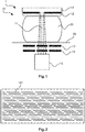
- Figs. 3 and 4 schematically and exemplarily show embodiments of a grating.
- at least one of the source grating 12, the phase grating 13 or the absorber grating 14 comprises at least one first segment 161 and at least one second segment 162 arranged adjacent to each other in a direction perpendicular to the direction of the line detector 15 and to the X-ray beam 11 direction.
- Each of the at least one first and second segments 161, 162 of the grating comprises a grating structure of a respective transmission characteristic, for example in form of grating lines 163, also referred to as stripes, of different transmission characteristic.
- the first and the second segments 161, 162 mutually differ in terms of the respective grating structure such that the first and the second segments 161, 162 differ in terms of the respective transmission characteristic, as will be shown further below to Figs. 3 and 4 .
- the X-ray imaging device 1 is arranged for moving the line detector 15 and at least one of the source grating 12, the phase grating 13 or the absorber grating 14, between a first relative position and a second relative position, such that in the first relative position, a portion of the X-ray beam during operation passes through the first segment 161 and subsequently illuminates a respective sensor line 151, while the second segment 162 is arranged outside said portion of the X-ray beam, and that in the second relative position, said portion of the X-ray beam during operation passes through the second segment 162 and subsequently illuminates said respective sensor line 151, while the first segment 161 is arranged outside said portion of the X-ray beam.
- X-ray imaging device 1 may realize the movement from the first relative position to the second relative position by moving, e.g. translating in a direction perpendicular to the direction of the line detector 15, at least one of the source grating 12, the phase grating 13 or the absorber grating 14 with respect to the line detector 15.
- the X-ray imaging device may employ an actuator known per se to the person skilled in the art for realizing such movement between the first and second relative positions.
- At least one of the source grating 12, the phase grating 13 or the absorber grating 14 comprises a plurality of first segments 161 and an identical plurality of second segments 162. More specifically, the pluralities of segments 161, 162 equal the number of sensor lines 151 as comprised in the line detector 15.
- the first segments 161 and the second segments 162 are arranged adjacent to each other, in alternating manner, in a direction perpendicular to the direction of the line detector 15.
- the X-ray imaging device 1 is arranged for moving the line detector 15 and at least one of the source grating 12, the phase grating 13 or the absorber grating 14, between a first relative position and a second relative position.
- the portions of the X-ray beam during operation pass through respective first segments 161 and subsequently illuminate respective sensor lines 151 of the line detector 15 for detection, while the second segments 162 are arranged outside said portions of the X-ray beam. More specifically, in the second relative position the second segments 162 project along the X-ray beam onto respective spaces between neighboring sensor lines 151.
- the portions of the X-ray beam during operation pass through respective second segments 162 and subsequently illuminate said respective sensor lines 151 of the line detector 15 for detection, while the first segments 161 are arranged outside said portions of the X-ray beam. More specifically, in the second relative position the first segments 161 project along the X-ray beam onto said spaces between neighboring sensor lines 151.
- both the phase grating 13 and the absorber grating 14 comprise a plurality of first segments 161 and an identical plurality of second segments 162.
- the pluralities of segments 161, 162 equal the number of sensor lines 151 as comprised in the line detector 15.
- the first segments 161 comprised in the phase grating 13 need not be identical to those comprised in the absorber grating 14, however, they are compatible with the first segments 161 comprised in the absorber grating 14 such that they constitute a functioning interferometric unit. This applies mutatis mutandis to the second segments 162 comprised in the phase grating 13 and those comprised in the absorber grating 14.
- the X-ray imaging device 1 is arranged for moving the line detector 15 and the phase grating 13 and the absorber grating 14 in combination, between the first relative position and the second relative position.
- the portions of the X-ray beam during operation pass through respective first segments 161 of both the phase grating 13 and the absorber grating 14 and subsequently illuminate respective sensor lines 151 of the line detector 15 for detection, while the second segments 162 of both the phase grating 13 and the absorber grating 14 are arranged outside said portions of the X-ray beam. More specifically, in the first relative position the second segments 162 project along the X-ray beam onto respective spaces between neighboring sensor lines 151.
- the portions of the X-ray beam during operation pass through respective second segments 162 of both the phase grating 13 and the absorber grating 14 and subsequently illuminate said respective sensor lines 151 of the line detector 15 for detection, while the first segments 161 of both the phase grating 13 and the absorber grating 14 are arranged outside said portions of the X-ray beam. More specifically, in the second relative position the first segments 161 project along the X-ray beam onto said spaces between neighboring sensor lines 151.
- a frame 16 is provided comprising the first and second segments.
- the processing unit of the X-ray imaging system 1 is arranged for controlling a relative movement between the X-ray imaging device 10 and the object-receiving device 20.
- the X-ray imaging system 1 is configured to keep the object-receiving device 20 stationary during operation, and to realize said relative movement by moving, e.g. rotating, a movable gantry to which the line detector 15 and the at least one grating but preferably all of the source grating 12, the phase grating 13 or the absorber grating 14 are mounted, relative to the object-receiving device 20.
- the processing unit of the X-ray imaging system 1 is alternatively, or in addition, arranged for controlling a movement from the line detector and the at least one grating relative to each other from the first to the second relative position, and vice versa.
- Fig. 3 shows schematically and exemplarily an embodiment of a grating.
- the grating may comprise a frame 16 comprising a first segment 161 and a second segment 162 arranged adjacent to each other in a direction perpendicular to the direction of the line detector 15.
- Each of the first and the second segments 161, 162 of the grating comprise grating lines 163 as stripes of different transmission characteristic, or transmission functions.
- the first and the second segments 161, 162 differ from each other in view of the grating lines 163. As shown in Fig.
- the grating structure, such as the grating lines 163, of the first segment 161 has a first grating pitch and the grating structure, such as the grating lines 163, of the second segment 162 has a second grating pitch that differs from the first grating pitch.
- the first segment 161 has a relatively large grating pitch, hence being suitable for relatively low design energy.
- the second segment 162 has a relatively small grating pitch, hence being suitable for relatively high design energy.
- the notion is to have a rigid interferometer box with a fixed distance d between the phase grating 13 and the absorber grating 14.
- the height of the phase gratings may also be different in order to achieve the desired phase shift.
- the shape of the gratings may be different, for example the first one may be a rectangular grating and the second one may be a triangular grating.
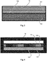
- Fig. 4 shows schematically and exemplarily an embodiment of a grating.
- the grating may comprise a frame 16 (as an option) comprising a first segment 161, a second segment 162 and at least one third segment 164 arranged adjacent to each other in a direction perpendicular to the direction of the line detector 15 and to the X-ray beam 11 direction.
- Each of the three segments of the grating comprises grating lines 163 of different transmission characteristic.
- the X-ray imaging device is arranged for moving the line detector 15 and the at least one grating relative to each other also to a third relative position, such that in the third relative position, the portions of the X-ray beam during operation pass through the at least one third segment, while the first and second segments 161, 162 are arranged outside the portions of the X-ray beam, and that in the first and second relative position, the at least one third segment is arranged outside the portions of the X-ray beam.
- a first segment 161 is provided for the acquisition of conventional data
- a second segment 162 is provided for the acquisition of gradients in an orientation "x”
- a third segment 164 is provided for the acquisition of gradients in an orientation "y", wherein y is essentially perpendicular to x.
- first segment 161 is placed above the line detector sensor, conventional scanning is performed
- second segment 162 is placed above the line detector sensor, a gradient in x-direction is measured
- the third segment 164 is placed above the line detector sensor, a gradient in y-direction is measured.
- at least a further segment (not shown) with a grating orientation of e.g. 45° in between the second and third segments 162, 164.
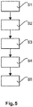
- Fig. 5 shows a schematic overview of steps of an X-ray imaging method. The method comprises the following steps, not necessarily in this order:
- a computer program or a computer program element is provided that is characterized by being adapted to execute the method steps of the method according to one of the preceding embodiments, on an appropriate system.
- the computer program element might therefore be stored on a computer unit, which might also be part of an embodiment of the present invention.
- This computing unit may be adapted to perform or induce a performing of the steps of the method described above. Moreover, it may be adapted to operate the components of the above described apparatus.
- the computing unit can be adapted to operate automatically and/or to execute the orders of a user.
- a computer program may be loaded into a working memory of a data processor.
- the data processor may thus be equipped to carry out the method of the invention.
- This exemplary embodiment of the invention covers both, a computer program that right from the beginning uses the invention and a computer program that by means of an up-date turns an existing program into a program that uses the invention.
- the computer program element might be able to provide all necessary steps to fulfil the procedure of an exemplary embodiment of the method as described above.
- a computer readable medium such as a CD-ROM
- the computer readable medium has a computer program element stored on it, which computer program element is described by the preceding section.
- a computer program may be stored and/or distributed on a suitable medium, such as an optical storage medium or a solid state medium supplied together with or as part of other hardware, but may also be distributed in other forms, such as via the internet or other wired or wireless telecommunication systems.
- a suitable medium such as an optical storage medium or a solid state medium supplied together with or as part of other hardware, but may also be distributed in other forms, such as via the internet or other wired or wireless telecommunication systems.
- the computer program may also be presented over a network like the World Wide Web and can be downloaded into the working memory of a data processor from such a network.
- a medium for making a computer program element available for downloading is provided, which computer program element is arranged to perform a method according to one of the previously described embodiments of the invention.
Claims (15)
- Röntgenbildgebungsvorrichtung (10), umfassend:eine Röntgenquellenanordnung zum Bereitstellen eines Röntgenstrahls (11); mindestens ein Gitter (13, 14); undeinen Zeilendetektor (15) mit einer Vielzahl von Sensorzeilen, wobei die Sensorzeilen jeweils durch eine Vielzahl von Sensorelementen bereitgestellt werden, und wobei die Sensorzeilen zum Erkennen jeweiliger Abschnitte des Röntgenstrahls (11) bereitgestellt sind, die das mindestens eine Gitter während des Betriebs durchlaufen;wobei die Röntgenbildgebungsvorrichtung zum Bewegen des Zeilendetektors (15) und eines relativ dazu abzubildenden Objekts (21) angeordnet ist, sodass als Reaktion auf die Abschnitte des Röntgenstrahls eine Anzahl von Interferenzmustern an zugehörigen unterschiedlichen relativen Positionen des Zeilendetektors und des Objekts zum Rekonstruieren des Bildes des Objekts (21) erkennbar sind;wobei das mindestens eine Gitter (13, 14) mindestens ein erstes Segment (161) und mindestens ein zweites Segment (162) umfasst, die in einer Richtung senkrecht zur Richtung des Zeilendetektors (15) benachbart voneinander angeordnet sind; undwobei die Röntgenbildgebungsvorrichtung zum Bewegen des Zeilendetektors (15) und des mindestens einen Gitters relativ zueinander zwischen mindestens einer ersten relativen Position und einer zweiten relativen Position angeordnet ist, so dass in der ersten relativen Position ein Abschnitt des Röntgenstrahls (11) während des Betriebs durch das mindestens eine erste Segment (161) geht und anschließend an der eindimensionalen Sensorzeile zur Erkennung eingeht, während das mindestens eine zweite Segment (162) außerhalb des Abschnitts des Röntgenstrahls (11) angeordnet ist, sodass es entlang des Röntgenstrahls auf die Fläche zwischen benachbarten Sensorzeilen vorsteht, und wobei in der zweiten relativen Position der Abschnitt des Röntgenstrahls (11) während des Betriebs durch mindestens ein Segment (162) geht und anschließend an der eindimensionalen Sensorzeile zur Erkennung eingeht, während das mindestens eine erste Segment (161) außerhalb des Abschnitts des Röntgenstrahls (11) angeordnet ist, sodass es entlang des Röntgenstrahls auf die Fläche zwischen benachbarten Sensorzeilen vorsteht.
- Röntgenbildgebungsvorrichtung (10) nach Anspruch 1, wobei jedes von erstem und zweitem Segment (161, 162) eine Gitterstruktur (163) einer jeweiligen Übertragungscharakteristik umfasst und wobei sich das erste und das zweite Segment (161, 162) hinsichtlich der jeweiligen Gitterstruktur (163) derart unterscheiden, dass sich das erste und das zweite Segment (161, 162) hinsichtlich der jeweiligen Übertragungscharakteristik unterscheiden.
- Röntgenbildgebungsvorrichtung (10) nach Anspruch 2, wobei die Gitterstruktur (163) des ersten Segments (161) eine erste Gitterteilung aufweist; und
wobei die Gitterstruktur (163) des zweiten Segments (162) eine zweite Gitterteilung aufweist, die sich von der ersten Gitterteilung unterscheidet. - Röntgenbildgebungsvorrichtung (10) nach Anspruch 2 oder 3, wobei die Gitterstruktur (163) des ersten Segments (161) eine erste Ausrichtung aufweist; und
wobei die Gitterstruktur (163) des zweiten Segments (162) eine zweite Ausrichtung aufweist, die sich von der ersten Ausrichtung unterscheidet. - Röntgenbildgebungsvorrichtung (10) nach Anspruch 2, 3 oder 4, wobei die Gitterstruktur des ersten Segments (161) eine erste Geometrie aufweist; und
wobei die Gitterstruktur des zweiten Segments (162) eine zweite Geometrie aufweist, die sich von der ersten Geometrie unterscheidet. - Röntgenbildgebungsvorrichtung (10) nach einem der vorstehenden Ansprüche, wobei
das mindestens eine Gitter einen Rahmen (16) umfasst; und
wobei der Rahmen mindestens das erste und das zweite Segment umfasst. - Röntgenbildgebungsvorrichtung (10) nach einem der vorstehenden Ansprüche, wobei
das mindestens eine Gitter (13) mindestens ein drittes Segment (164) umfasst, das in einer Richtung senkrecht zur Richtung des Zeilendetektors (15) benachbart des zweiten Segments (162) angeordnet ist;
wobei sich das mindestens eine dritte Segment (164) von dem ersten und dem zweiten Segment (161, 162) hinsichtlich der jeweiligen Gitterstruktur (163) und der jeweiligen Übertragungscharakteristik unterscheidet; und
wobei die Röntgenbildgebungsvorrichtung zum Bewegen des Zeilendetektors und des mindestens einen Gitters relativ dazu jeweils auch zu einer dritten relativen Position angeordnet ist, sodass in der dritten relativen Position der Abschnitt des Röntgenstrahls während des Betriebs das mindestens eine dritte Segment durchläuft, während das erste und das zweite Segment außerhalb des Abschnitts des Röntgenstrahls angeordnet sind, und dass das mindestens eine dritte Segment in der ersten und zweiten relativen Position außerhalb des Abschnitts des Röntgenstrahls angeordnet ist. - Röntgenbildgebungsvorrichtung (10) nach einem der vorstehenden Ansprüche, wobei die Röntgenbildgebungsvorrichtung (10) eine Röntgendifferentialphasen-Kontrastbildgebungsvorrichtung (10) ist; und
wobei das mindestens eine Gitter als ein Phasengitter (13) oder als ein Absorbergitter (14) bereitgestellt ist. - Röntgenbildgebungsvorrichtung (10) nach einem der Ansprüche 1 bis 7, wobei zwei des mindestens einen Gitters bereitgestellt sind;
wobei eines der zwei Gitter ein Phasengitter (13) ist und das andere der zwei Gitter ein Absorbergitter (14) ist, das relativ zum Phasengitter stromabwärts des Röntgenstrahls installiert ist; und
wobei sich die ersten Segmente des Phasengitters von den ersten Segmenten des Absorbergitters unterscheiden; und/oder sich die zweiten Segmente des Phasengitters von den zweiten Segmenten des Absorbergitters unterscheiden. - Röntgenbildgebungsvorrichtung (10) nach einem der vorstehenden Ansprüche, weiter umfassend eine Schiebereinheit, die zum Bewegen des mindestens einen Gitters (13, 14) relativ zum Zeilendetektor (15) konfiguriert ist.
- Röntgenbildgebungsvorrichtung (10) nach einem der vorstehenden Ansprüche, wobei
das mindestens eine Gitter (13, 14) und der Zeilendetektor (15) an einer beweglichen Gantry montiert sind; und
wobei eine Gantry-Schiebereinheit bereitgestellt ist, die zum Bewegen der beweglichen Gantry relativ zu dem abzubildenden Objekt (21) konfiguriert ist. - Röntgenbildgebungsvorrichtung (1), umfassend:eine Röntgenbildgebungsvorrichtung (10) nach einem der vorstehenden Ansprüche; eine Verarbeitungseinheit; undeine Objektaufnahmeeinheit (20), die zum Aufnehmen eines abzubildenden Objekts (21) konfiguriert ist;wobei die Verarbeitungseinheit zum Steuern einer relativen Bewegung der Röntgenbildgebungsvorrichtung (10) und der Objektaufnahmevorrichtung (20) zueinander und/oder einer relativen Bewegung des mindestens einen Gitters (13, 14) und des Zeilendetektors (15) der Röntgenbildgebungsvorrichtung (10) in Bezug aufeinander konfiguriert ist.
- Röntgenbildgebungsverfahren, umfassend die folgenden Schritte:Bereitstellen eines Röntgenstrahls (11) mit einer Röntgenquellenanordnung für ein abzubildendes Objekt;Erzeugen eines Interferenzmusters mit mindestens einem Gitter (13, 14), das mindestens ein erstes Segment (161) und ein zweites Segment (162) umfasst, die in einer Richtung senkrecht zur Richtung des Zeilendetektors (15) benachbart voneinander angeordnet sind;relatives Bewegen eines Zeilendetektors (15) mit einer Vielzahl von Sensorzeilen, wobei die Sensorzeilen jeweils durch eine Vielzahl von Sensorelementen bereitgestellt werden, und wobei die Sensorzeilen zum Erkennen jeweiliger Abschnitte des Röntgenstrahls (11) bereitgestellt sind, die das mindestens eine Gitter während des Betriebs und das abzubildende Objekt (21) durchlaufen, sodass als Reaktion auf die Abschnitte des Röntgenstrahls eine Anzahl von Interferenzmustern an entsprechenden unterschiedlichen relativen Positionen des Zeilendetektors und des Objekts zum Rekonstruieren eines Bildes des Objekts (21) erkannt werden;relatives Bewegen des Zeilendetektors (15) und des mindestens einen Gitters zwischen mindestens einer ersten relativen Position und einer zweiten relativen Position, so dass in der ersten relativen Position ein Abschnitt des Röntgenstrahls (11) während des Betriebs durch das mindestens eine erste Segment (161) geht und anschließend an der eindimensionalen Sensorzeile zur Erkennung eingeht, während das mindestens eine zweite Segment (162) außerhalb des Abschnitts des Röntgenstrahls (11) angeordnet ist, sodass es entlang des Röntgenstrahls auf die Fläche zwischen benachbarten Sensorzeilen vorsteht, und wobei in der zweiten relativen Position der Abschnitt des Röntgenstrahls (11) während des Betriebs durch mindestens ein Segment (162) geht und anschließend an der eindimensionalen Sensorzeile zur Erkennung eingeht, während das mindestens eine erste Segment (161) außerhalb des Abschnitts des Röntgenstrahls (11) angeordnet ist, sodass es entlang des Röntgenstrahls auf die Fläche zwischen benachbarten Sensorzeilen vorsteht; undErkennen des Abschnitts des Röntgenstrahls (11), der das mindestens eine Gitter durchläuft.
- Computerprogrammelement zum Steuern einer Röntgenbildgebungsvorrichtung nach einem der Ansprüche 1 bis 11 oder ein Röntgenabbildungssystem nach Anspruch 12, das bei Ausführung durch eine Verarbeitungseinheit ausgelegt ist, die Verfahrensschritte des vorstehenden Anspruchs durchzuführen.
- Computerlesbares Medium, das darauf gespeichert das Programmelement des vorstehenden Anspruchs aufweist.
Applications Claiming Priority (2)
| Application Number | Priority Date | Filing Date | Title |
|---|---|---|---|
| EP14177486 | 2014-07-17 | ||
| PCT/EP2015/065405 WO2016008762A1 (en) | 2014-07-17 | 2015-07-07 | X-ray imaging device |
Publications (2)
| Publication Number | Publication Date |
|---|---|
| EP3169239A1 EP3169239A1 (de) | 2017-05-24 |
| EP3169239B1 true EP3169239B1 (de) | 2018-10-31 |
Family
ID=51211608
Family Applications (1)
| Application Number | Title | Priority Date | Filing Date |
|---|---|---|---|
| EP15734376.5A Not-in-force EP3169239B1 (de) | 2014-07-17 | 2015-07-07 | Differenzielle phasenkontrastbildgebungsvorrichtung mit einem oder mehreren beweglichen gittern |
Country Status (6)
| Country | Link |
|---|---|
| US (1) | US10368815B2 (de) |
| EP (1) | EP3169239B1 (de) |
| JP (1) | JP6475315B2 (de) |
| CN (1) | CN106535767B (de) |
| RU (1) | RU2695311C2 (de) |
| WO (1) | WO2016008762A1 (de) |
Families Citing this family (6)
| Publication number | Priority date | Publication date | Assignee | Title |
|---|---|---|---|---|
| WO2016104008A1 (ja) * | 2014-12-22 | 2016-06-30 | 株式会社島津製作所 | 放射線位相差撮影装置 |
| JP6753342B2 (ja) * | 2017-03-15 | 2020-09-09 | 株式会社島津製作所 | 放射線格子検出器およびx線検査装置 |
| US10441234B2 (en) * | 2017-06-15 | 2019-10-15 | Shimadzu Corporation | Radiation-phase-contrast imaging device |
| JP6743983B2 (ja) * | 2017-10-31 | 2020-08-19 | 株式会社島津製作所 | X線位相差撮像システム |
| CN111089870B (zh) * | 2019-12-12 | 2022-07-19 | 中国科学院苏州生物医学工程技术研究所 | 基于两次成像的x射线光栅相衬成像方法及系统、存储介质、设备 |
| US11860319B2 (en) * | 2022-03-10 | 2024-01-02 | GE Precision Healthcare LLC | High-resolution detector having a reduced number of pixels |
Family Cites Families (16)
| Publication number | Priority date | Publication date | Assignee | Title |
|---|---|---|---|---|
| US5400379A (en) * | 1994-02-25 | 1995-03-21 | General Electric Company | Multi-slice x-ray CT using a detector mask |
| DE102009004702B4 (de) * | 2009-01-15 | 2019-01-31 | Paul Scherer Institut | Anordnung und Verfahren zur projektiven und/oder tomographischen Phasenkontrastbildgebung mit Röntgenstrahlung |
| CN102365687B (zh) * | 2009-03-27 | 2015-08-19 | 皇家飞利浦电子股份有限公司 | 消色差的相衬成像 |
| BRPI1015157A2 (pt) * | 2009-04-01 | 2016-04-19 | Brookhaven Science Ass Llc | colimador de múltiplas aberturas entrelaçadas para aplicações em imagiologia por radiação tridimensional. |
| JP2010253194A (ja) | 2009-04-28 | 2010-11-11 | Fujifilm Corp | 放射線位相画像撮影装置 |
| EP2442722B1 (de) * | 2009-06-16 | 2017-03-29 | Koninklijke Philips N.V. | Korrekturverfahren für differenzielle phasenkontrastbildgebung |
| JP5213923B2 (ja) * | 2010-01-29 | 2013-06-19 | キヤノン株式会社 | X線撮像装置およびx線撮像方法 |
| WO2012029005A1 (en) | 2010-09-03 | 2012-03-08 | Koninklijke Philips Electronics N.V. | Differential phase-contrast imaging with improved sampling |
| EP2630476B1 (de) * | 2010-10-19 | 2017-12-13 | Koninklijke Philips N.V. | Differenzielle phasenkontrastbildgebung |
| JP2012166010A (ja) | 2011-01-26 | 2012-09-06 | Fujifilm Corp | 放射線画像撮影装置および放射線画像検出器 |
| WO2013111050A1 (en) * | 2012-01-24 | 2013-08-01 | Koninklijke Philips N.V. | Multi-directional phase contrast x-ray imaging |
| DE102012224258A1 (de) | 2012-12-21 | 2014-06-26 | Siemens Aktiengesellschaft | Röntgenaufnahmesystem zur differentiellen Phasenkontrast-Bildgebung eines Untersuchungsobjekts mit Phase-Stepping sowie angiographisches Untersuchungsverfahren |
| WO2014100063A1 (en) * | 2012-12-21 | 2014-06-26 | Carestream Health, Inc. | Medical radiographic grating based differential phase contrast imaging |
| JP2014142338A (ja) * | 2012-12-27 | 2014-08-07 | Canon Inc | 干渉計及び被検体情報取得システム |
| CN104837409B (zh) | 2013-09-30 | 2019-08-13 | 皇家飞利浦有限公司 | 具有可移动光栅的微分相位衬度成像装置 |
| JP2014100063A (ja) | 2014-03-03 | 2014-05-29 | Fuji Electric Co Ltd | 電源装置 |
-
2015
- 2015-07-07 EP EP15734376.5A patent/EP3169239B1/de not_active Not-in-force
- 2015-07-07 RU RU2017103455A patent/RU2695311C2/ru active
- 2015-07-07 CN CN201580039025.5A patent/CN106535767B/zh not_active Expired - Fee Related
- 2015-07-07 US US15/325,551 patent/US10368815B2/en not_active Expired - Fee Related
- 2015-07-07 WO PCT/EP2015/065405 patent/WO2016008762A1/en active Application Filing
- 2015-07-07 JP JP2017502174A patent/JP6475315B2/ja not_active Expired - Fee Related
Non-Patent Citations (1)
| Title |
|---|
| None * |
Also Published As
| Publication number | Publication date |
|---|---|
| RU2695311C2 (ru) | 2019-07-22 |
| EP3169239A1 (de) | 2017-05-24 |
| JP2017521170A (ja) | 2017-08-03 |
| CN106535767B (zh) | 2020-05-01 |
| JP6475315B2 (ja) | 2019-02-27 |
| US10368815B2 (en) | 2019-08-06 |
| RU2017103455A3 (de) | 2019-01-31 |
| WO2016008762A1 (en) | 2016-01-21 |
| US20170156686A1 (en) | 2017-06-08 |
| RU2017103455A (ru) | 2018-08-17 |
| CN106535767A (zh) | 2017-03-22 |
Similar Documents
| Publication | Publication Date | Title |
|---|---|---|
| EP3169239B1 (de) | Differenzielle phasenkontrastbildgebungsvorrichtung mit einem oder mehreren beweglichen gittern | |
| JP5462408B2 (ja) | X線源回折格子のステップ撮像システムおよび撮像方法 | |
| EP2509503B1 (de) | Vorrichtung für phasenkontrastbildgebung mit einem verschiebbaren röntgendetektorelement und verfahren | |
| US10420521B2 (en) | Grating device for an X-ray imaging device | |
| EP2611364B1 (de) | Differenzielle phasenkontrastbildgebung mit verbesserter abtastung | |
| EP3048441B1 (de) | System und verfahren für röntgenstrahlenphasenkontrastbildgebung | |
| JP6422123B2 (ja) | 放射線画像生成装置 | |
| EP2884899B1 (de) | Ausrichten der source-grating-zu-phase-grating-distanz für phasenabstimmung vielfacher ordnung bei der differenzialphasenkontrastbildgebung | |
| CN101952900B (zh) | 用于相位对比成像的x射线探测器 | |
| JP5777360B2 (ja) | X線撮像装置 | |
| EP3140641B1 (de) | Beugungsgitteransatz für röntgengitterinterferometrie im abtastmodus | |
| US20120250823A1 (en) | Calibration of differential phase-contrast imaging systems | |
| CN107847199B (zh) | 具有全视场探测器的扫描x射线装置 | |
| US20180140269A1 (en) | X-ray imaging | |
| WO2019057915A1 (en) | X-RAY IMAGING REFERENCE SCAN | |
| JP2019537482A (ja) | 位相コントラスト像形成データから多エネルギーデータを生成するための装置 | |
| RU2708816C2 (ru) | Детектор и система визуализации для рентгеновской фазово-контрастной визуализации томосинтеза | |
| EP3934537A1 (de) | System zur röntgendunkelfeld-, phasenkontrast- und attenuationstomosynthesebilderfassung | |
| Arfelli et al. | Recent developments on techniques for differential phase imaging at the medical beamline of ELETTRA |
Legal Events
| Date | Code | Title | Description |
|---|---|---|---|
| STAA | Information on the status of an ep patent application or granted ep patent |
Free format text: STATUS: THE INTERNATIONAL PUBLICATION HAS BEEN MADE |
|
| PUAI | Public reference made under article 153(3) epc to a published international application that has entered the european phase |
Free format text: ORIGINAL CODE: 0009012 |
|
| STAA | Information on the status of an ep patent application or granted ep patent |
Free format text: STATUS: REQUEST FOR EXAMINATION WAS MADE |
|
| 17P | Request for examination filed |
Effective date: 20170217 |
|
| AK | Designated contracting states |
Kind code of ref document: A1 Designated state(s): AL AT BE BG CH CY CZ DE DK EE ES FI FR GB GR HR HU IE IS IT LI LT LU LV MC MK MT NL NO PL PT RO RS SE SI SK SM TR |
|
| AX | Request for extension of the european patent |
Extension state: BA ME |
|
| DAV | Request for validation of the european patent (deleted) | ||
| DAX | Request for extension of the european patent (deleted) | ||
| GRAP | Despatch of communication of intention to grant a patent |
Free format text: ORIGINAL CODE: EPIDOSNIGR1 |
|
| STAA | Information on the status of an ep patent application or granted ep patent |
Free format text: STATUS: GRANT OF PATENT IS INTENDED |
|
| INTG | Intention to grant announced |
Effective date: 20180517 |
|
| GRAS | Grant fee paid |
Free format text: ORIGINAL CODE: EPIDOSNIGR3 |
|
| GRAA | (expected) grant |
Free format text: ORIGINAL CODE: 0009210 |
|
| STAA | Information on the status of an ep patent application or granted ep patent |
Free format text: STATUS: THE PATENT HAS BEEN GRANTED |
|
| AK | Designated contracting states |
Kind code of ref document: B1 Designated state(s): AL AT BE BG CH CY CZ DE DK EE ES FI FR GB GR HR HU IE IS IT LI LT LU LV MC MK MT NL NO PL PT RO RS SE SI SK SM TR |
|
| REG | Reference to a national code |
Ref country code: CH Ref legal event code: EP Ref country code: GB Ref legal event code: FG4D |
|
| REG | Reference to a national code |
Ref country code: AT Ref legal event code: REF Ref document number: 1058409 Country of ref document: AT Kind code of ref document: T Effective date: 20181115 |
|
| REG | Reference to a national code |
Ref country code: DE Ref legal event code: R096 Ref document number: 602015019101 Country of ref document: DE |
|
| REG | Reference to a national code |
Ref country code: IE Ref legal event code: FG4D |
|
| REG | Reference to a national code |
Ref country code: DE Ref legal event code: R084 Ref document number: 602015019101 Country of ref document: DE |
|
| REG | Reference to a national code |
Ref country code: GB Ref legal event code: 746 Effective date: 20181126 |
|
| REG | Reference to a national code |
Ref country code: NL Ref legal event code: MP Effective date: 20181031 |
|
| REG | Reference to a national code |
Ref country code: LT Ref legal event code: MG4D |
|
| REG | Reference to a national code |
Ref country code: AT Ref legal event code: MK05 Ref document number: 1058409 Country of ref document: AT Kind code of ref document: T Effective date: 20181031 |
|
| PG25 | Lapsed in a contracting state [announced via postgrant information from national office to epo] |
Ref country code: BG Free format text: LAPSE BECAUSE OF FAILURE TO SUBMIT A TRANSLATION OF THE DESCRIPTION OR TO PAY THE FEE WITHIN THE PRESCRIBED TIME-LIMIT Effective date: 20190131 Ref country code: LT Free format text: LAPSE BECAUSE OF FAILURE TO SUBMIT A TRANSLATION OF THE DESCRIPTION OR TO PAY THE FEE WITHIN THE PRESCRIBED TIME-LIMIT Effective date: 20181031 Ref country code: FI Free format text: LAPSE BECAUSE OF FAILURE TO SUBMIT A TRANSLATION OF THE DESCRIPTION OR TO PAY THE FEE WITHIN THE PRESCRIBED TIME-LIMIT Effective date: 20181031 Ref country code: NO Free format text: LAPSE BECAUSE OF FAILURE TO SUBMIT A TRANSLATION OF THE DESCRIPTION OR TO PAY THE FEE WITHIN THE PRESCRIBED TIME-LIMIT Effective date: 20190131 Ref country code: IS Free format text: LAPSE BECAUSE OF FAILURE TO SUBMIT A TRANSLATION OF THE DESCRIPTION OR TO PAY THE FEE WITHIN THE PRESCRIBED TIME-LIMIT Effective date: 20190228 Ref country code: AT Free format text: LAPSE BECAUSE OF FAILURE TO SUBMIT A TRANSLATION OF THE DESCRIPTION OR TO PAY THE FEE WITHIN THE PRESCRIBED TIME-LIMIT Effective date: 20181031 Ref country code: ES Free format text: LAPSE BECAUSE OF FAILURE TO SUBMIT A TRANSLATION OF THE DESCRIPTION OR TO PAY THE FEE WITHIN THE PRESCRIBED TIME-LIMIT Effective date: 20181031 Ref country code: LV Free format text: LAPSE BECAUSE OF FAILURE TO SUBMIT A TRANSLATION OF THE DESCRIPTION OR TO PAY THE FEE WITHIN THE PRESCRIBED TIME-LIMIT Effective date: 20181031 Ref country code: PL Free format text: LAPSE BECAUSE OF FAILURE TO SUBMIT A TRANSLATION OF THE DESCRIPTION OR TO PAY THE FEE WITHIN THE PRESCRIBED TIME-LIMIT Effective date: 20181031 Ref country code: HR Free format text: LAPSE BECAUSE OF FAILURE TO SUBMIT A TRANSLATION OF THE DESCRIPTION OR TO PAY THE FEE WITHIN THE PRESCRIBED TIME-LIMIT Effective date: 20181031 |
|
| PG25 | Lapsed in a contracting state [announced via postgrant information from national office to epo] |
Ref country code: AL Free format text: LAPSE BECAUSE OF FAILURE TO SUBMIT A TRANSLATION OF THE DESCRIPTION OR TO PAY THE FEE WITHIN THE PRESCRIBED TIME-LIMIT Effective date: 20181031 Ref country code: NL Free format text: LAPSE BECAUSE OF FAILURE TO SUBMIT A TRANSLATION OF THE DESCRIPTION OR TO PAY THE FEE WITHIN THE PRESCRIBED TIME-LIMIT Effective date: 20181031 Ref country code: GR Free format text: LAPSE BECAUSE OF FAILURE TO SUBMIT A TRANSLATION OF THE DESCRIPTION OR TO PAY THE FEE WITHIN THE PRESCRIBED TIME-LIMIT Effective date: 20190201 Ref country code: SE Free format text: LAPSE BECAUSE OF FAILURE TO SUBMIT A TRANSLATION OF THE DESCRIPTION OR TO PAY THE FEE WITHIN THE PRESCRIBED TIME-LIMIT Effective date: 20181031 Ref country code: RS Free format text: LAPSE BECAUSE OF FAILURE TO SUBMIT A TRANSLATION OF THE DESCRIPTION OR TO PAY THE FEE WITHIN THE PRESCRIBED TIME-LIMIT Effective date: 20181031 Ref country code: PT Free format text: LAPSE BECAUSE OF FAILURE TO SUBMIT A TRANSLATION OF THE DESCRIPTION OR TO PAY THE FEE WITHIN THE PRESCRIBED TIME-LIMIT Effective date: 20190301 |
|
| PG25 | Lapsed in a contracting state [announced via postgrant information from national office to epo] |
Ref country code: CZ Free format text: LAPSE BECAUSE OF FAILURE TO SUBMIT A TRANSLATION OF THE DESCRIPTION OR TO PAY THE FEE WITHIN THE PRESCRIBED TIME-LIMIT Effective date: 20181031 Ref country code: DK Free format text: LAPSE BECAUSE OF FAILURE TO SUBMIT A TRANSLATION OF THE DESCRIPTION OR TO PAY THE FEE WITHIN THE PRESCRIBED TIME-LIMIT Effective date: 20181031 Ref country code: IT Free format text: LAPSE BECAUSE OF FAILURE TO SUBMIT A TRANSLATION OF THE DESCRIPTION OR TO PAY THE FEE WITHIN THE PRESCRIBED TIME-LIMIT Effective date: 20181031 |
|
| REG | Reference to a national code |
Ref country code: DE Ref legal event code: R097 Ref document number: 602015019101 Country of ref document: DE |
|
| PG25 | Lapsed in a contracting state [announced via postgrant information from national office to epo] |
Ref country code: EE Free format text: LAPSE BECAUSE OF FAILURE TO SUBMIT A TRANSLATION OF THE DESCRIPTION OR TO PAY THE FEE WITHIN THE PRESCRIBED TIME-LIMIT Effective date: 20181031 Ref country code: SM Free format text: LAPSE BECAUSE OF FAILURE TO SUBMIT A TRANSLATION OF THE DESCRIPTION OR TO PAY THE FEE WITHIN THE PRESCRIBED TIME-LIMIT Effective date: 20181031 Ref country code: SK Free format text: LAPSE BECAUSE OF FAILURE TO SUBMIT A TRANSLATION OF THE DESCRIPTION OR TO PAY THE FEE WITHIN THE PRESCRIBED TIME-LIMIT Effective date: 20181031 Ref country code: RO Free format text: LAPSE BECAUSE OF FAILURE TO SUBMIT A TRANSLATION OF THE DESCRIPTION OR TO PAY THE FEE WITHIN THE PRESCRIBED TIME-LIMIT Effective date: 20181031 |
|
| PLBE | No opposition filed within time limit |
Free format text: ORIGINAL CODE: 0009261 |
|
| STAA | Information on the status of an ep patent application or granted ep patent |
Free format text: STATUS: NO OPPOSITION FILED WITHIN TIME LIMIT |
|
| 26N | No opposition filed |
Effective date: 20190801 |
|
| PG25 | Lapsed in a contracting state [announced via postgrant information from national office to epo] |
Ref country code: SI Free format text: LAPSE BECAUSE OF FAILURE TO SUBMIT A TRANSLATION OF THE DESCRIPTION OR TO PAY THE FEE WITHIN THE PRESCRIBED TIME-LIMIT Effective date: 20181031 |
|
| PG25 | Lapsed in a contracting state [announced via postgrant information from national office to epo] |
Ref country code: MC Free format text: LAPSE BECAUSE OF FAILURE TO SUBMIT A TRANSLATION OF THE DESCRIPTION OR TO PAY THE FEE WITHIN THE PRESCRIBED TIME-LIMIT Effective date: 20181031 |
|
| REG | Reference to a national code |
Ref country code: CH Ref legal event code: PL |
|
| PG25 | Lapsed in a contracting state [announced via postgrant information from national office to epo] |
Ref country code: TR Free format text: LAPSE BECAUSE OF FAILURE TO SUBMIT A TRANSLATION OF THE DESCRIPTION OR TO PAY THE FEE WITHIN THE PRESCRIBED TIME-LIMIT Effective date: 20181031 |
|
| REG | Reference to a national code |
Ref country code: BE Ref legal event code: MM Effective date: 20190731 |
|
| PG25 | Lapsed in a contracting state [announced via postgrant information from national office to epo] |
Ref country code: LU Free format text: LAPSE BECAUSE OF NON-PAYMENT OF DUE FEES Effective date: 20190707 Ref country code: LI Free format text: LAPSE BECAUSE OF NON-PAYMENT OF DUE FEES Effective date: 20190731 Ref country code: CH Free format text: LAPSE BECAUSE OF NON-PAYMENT OF DUE FEES Effective date: 20190731 Ref country code: BE Free format text: LAPSE BECAUSE OF NON-PAYMENT OF DUE FEES Effective date: 20190731 |
|
| PG25 | Lapsed in a contracting state [announced via postgrant information from national office to epo] |
Ref country code: IE Free format text: LAPSE BECAUSE OF NON-PAYMENT OF DUE FEES Effective date: 20190707 |
|
| PG25 | Lapsed in a contracting state [announced via postgrant information from national office to epo] |
Ref country code: CY Free format text: LAPSE BECAUSE OF FAILURE TO SUBMIT A TRANSLATION OF THE DESCRIPTION OR TO PAY THE FEE WITHIN THE PRESCRIBED TIME-LIMIT Effective date: 20181031 |
|
| PG25 | Lapsed in a contracting state [announced via postgrant information from national office to epo] |
Ref country code: HU Free format text: LAPSE BECAUSE OF FAILURE TO SUBMIT A TRANSLATION OF THE DESCRIPTION OR TO PAY THE FEE WITHIN THE PRESCRIBED TIME-LIMIT; INVALID AB INITIO Effective date: 20150707 Ref country code: MT Free format text: LAPSE BECAUSE OF FAILURE TO SUBMIT A TRANSLATION OF THE DESCRIPTION OR TO PAY THE FEE WITHIN THE PRESCRIBED TIME-LIMIT Effective date: 20181031 |
|
| PGFP | Annual fee paid to national office [announced via postgrant information from national office to epo] |
Ref country code: FR Payment date: 20210726 Year of fee payment: 7 |
|
| PGFP | Annual fee paid to national office [announced via postgrant information from national office to epo] |
Ref country code: DE Payment date: 20210729 Year of fee payment: 7 Ref country code: GB Payment date: 20210726 Year of fee payment: 7 |
|
| PG25 | Lapsed in a contracting state [announced via postgrant information from national office to epo] |
Ref country code: MK Free format text: LAPSE BECAUSE OF FAILURE TO SUBMIT A TRANSLATION OF THE DESCRIPTION OR TO PAY THE FEE WITHIN THE PRESCRIBED TIME-LIMIT Effective date: 20181031 |
|
| REG | Reference to a national code |
Ref country code: DE Ref legal event code: R119 Ref document number: 602015019101 Country of ref document: DE |
|
| GBPC | Gb: european patent ceased through non-payment of renewal fee |
Effective date: 20220707 |
|
| PG25 | Lapsed in a contracting state [announced via postgrant information from national office to epo] |
Ref country code: FR Free format text: LAPSE BECAUSE OF NON-PAYMENT OF DUE FEES Effective date: 20220731 |
|
| PG25 | Lapsed in a contracting state [announced via postgrant information from national office to epo] |
Ref country code: GB Free format text: LAPSE BECAUSE OF NON-PAYMENT OF DUE FEES Effective date: 20220707 Ref country code: DE Free format text: LAPSE BECAUSE OF NON-PAYMENT OF DUE FEES Effective date: 20230201 |