EP3169010A1 - Twdm passive network with extended reach and capacity - Google Patents
Twdm passive network with extended reach and capacity Download PDFInfo
- Publication number
- EP3169010A1 EP3169010A1 EP16197732.7A EP16197732A EP3169010A1 EP 3169010 A1 EP3169010 A1 EP 3169010A1 EP 16197732 A EP16197732 A EP 16197732A EP 3169010 A1 EP3169010 A1 EP 3169010A1
- Authority
- EP
- European Patent Office
- Prior art keywords
- line terminal
- signal
- optical line
- multiplexer
- optical
- Prior art date
- Legal status (The legal status is an assumption and is not a legal conclusion. Google has not performed a legal analysis and makes no representation as to the accuracy of the status listed.)
- Granted
Links
- 230000003287 optical effect Effects 0.000 claims abstract description 276
- 238000011144 upstream manufacturing Methods 0.000 claims abstract description 86
- 230000003595 spectral effect Effects 0.000 claims abstract description 56
- 238000004891 communication Methods 0.000 claims abstract description 29
- 238000000034 method Methods 0.000 claims description 39
- 239000013307 optical fiber Substances 0.000 claims description 31
- 239000000835 fiber Substances 0.000 description 70
- 229920005560 fluorosilicone rubber Polymers 0.000 description 25
- 230000005540 biological transmission Effects 0.000 description 18
- 238000013461 design Methods 0.000 description 17
- 238000005516 engineering process Methods 0.000 description 7
- 238000010276 construction Methods 0.000 description 4
- 230000003321 amplification Effects 0.000 description 3
- 230000008901 benefit Effects 0.000 description 3
- 125000004122 cyclic group Chemical group 0.000 description 3
- 230000007423 decrease Effects 0.000 description 3
- QRXWMOHMRWLFEY-UHFFFAOYSA-N isoniazide Chemical compound NNC(=O)C1=CC=NC=C1 QRXWMOHMRWLFEY-UHFFFAOYSA-N 0.000 description 3
- 238000003199 nucleic acid amplification method Methods 0.000 description 3
- 239000004065 semiconductor Substances 0.000 description 3
- VYPSYNLAJGMNEJ-UHFFFAOYSA-N Silicium dioxide Chemical compound O=[Si]=O VYPSYNLAJGMNEJ-UHFFFAOYSA-N 0.000 description 2
- 230000008859 change Effects 0.000 description 2
- 239000006185 dispersion Substances 0.000 description 2
- 230000000694 effects Effects 0.000 description 2
- 238000002955 isolation Methods 0.000 description 2
- 230000007774 longterm Effects 0.000 description 2
- 239000000463 material Substances 0.000 description 2
- 230000007246 mechanism Effects 0.000 description 2
- 230000008569 process Effects 0.000 description 2
- 230000035945 sensitivity Effects 0.000 description 2
- RYGMFSIKBFXOCR-UHFFFAOYSA-N Copper Chemical compound [Cu] RYGMFSIKBFXOCR-UHFFFAOYSA-N 0.000 description 1
- 102100022824 Serum paraoxonase/arylesterase 2 Human genes 0.000 description 1
- 101710180998 Serum paraoxonase/arylesterase 2 Proteins 0.000 description 1
- 230000009286 beneficial effect Effects 0.000 description 1
- 230000002457 bidirectional effect Effects 0.000 description 1
- 230000000903 blocking effect Effects 0.000 description 1
- 239000000969 carrier Substances 0.000 description 1
- 238000006243 chemical reaction Methods 0.000 description 1
- 230000001010 compromised effect Effects 0.000 description 1
- 238000007596 consolidation process Methods 0.000 description 1
- 229910052802 copper Inorganic materials 0.000 description 1
- 239000010949 copper Substances 0.000 description 1
- 239000011521 glass Substances 0.000 description 1
- 239000003365 glass fiber Substances 0.000 description 1
- RGNPBRKPHBKNKX-UHFFFAOYSA-N hexaflumuron Chemical group C1=C(Cl)C(OC(F)(F)C(F)F)=C(Cl)C=C1NC(=O)NC(=O)C1=C(F)C=CC=C1F RGNPBRKPHBKNKX-UHFFFAOYSA-N 0.000 description 1
- 239000012535 impurity Substances 0.000 description 1
- 238000007726 management method Methods 0.000 description 1
- 238000013507 mapping Methods 0.000 description 1
- 239000002184 metal Substances 0.000 description 1
- 229910052751 metal Inorganic materials 0.000 description 1
- 238000012986 modification Methods 0.000 description 1
- 230000004048 modification Effects 0.000 description 1
- 230000009467 reduction Effects 0.000 description 1
- 230000008439 repair process Effects 0.000 description 1
- 239000000377 silicon dioxide Substances 0.000 description 1
- 238000001228 spectrum Methods 0.000 description 1
- 230000007480 spreading Effects 0.000 description 1
- 239000010409 thin film Substances 0.000 description 1
Images


Classifications
-
- H—ELECTRICITY
- H04—ELECTRIC COMMUNICATION TECHNIQUE
- H04J—MULTIPLEX COMMUNICATION
- H04J14/00—Optical multiplex systems
- H04J14/02—Wavelength-division multiplex systems
- H04J14/0201—Add-and-drop multiplexing
- H04J14/0202—Arrangements therefor
- H04J14/0209—Multi-stage arrangements, e.g. by cascading multiplexers or demultiplexers
-
- H—ELECTRICITY
- H04—ELECTRIC COMMUNICATION TECHNIQUE
- H04J—MULTIPLEX COMMUNICATION
- H04J14/00—Optical multiplex systems
- H04J14/02—Wavelength-division multiplex systems
- H04J14/0227—Operation, administration, maintenance or provisioning [OAMP] of WDM networks, e.g. media access, routing or wavelength allocation
- H04J14/0241—Wavelength allocation for communications one-to-one, e.g. unicasting wavelengths
- H04J14/0242—Wavelength allocation for communications one-to-one, e.g. unicasting wavelengths in WDM-PON
- H04J14/0245—Wavelength allocation for communications one-to-one, e.g. unicasting wavelengths in WDM-PON for downstream transmission, e.g. optical line terminal [OLT] to ONU
- H04J14/0247—Sharing one wavelength for at least a group of ONUs
-
- H—ELECTRICITY
- H04—ELECTRIC COMMUNICATION TECHNIQUE
- H04J—MULTIPLEX COMMUNICATION
- H04J14/00—Optical multiplex systems
- H04J14/02—Wavelength-division multiplex systems
- H04J14/0227—Operation, administration, maintenance or provisioning [OAMP] of WDM networks, e.g. media access, routing or wavelength allocation
- H04J14/0241—Wavelength allocation for communications one-to-one, e.g. unicasting wavelengths
- H04J14/0242—Wavelength allocation for communications one-to-one, e.g. unicasting wavelengths in WDM-PON
-
- H—ELECTRICITY
- H04—ELECTRIC COMMUNICATION TECHNIQUE
- H04B—TRANSMISSION
- H04B10/00—Transmission systems employing electromagnetic waves other than radio-waves, e.g. infrared, visible or ultraviolet light, or employing corpuscular radiation, e.g. quantum communication
- H04B10/25—Arrangements specific to fibre transmission
- H04B10/2575—Radio-over-fibre, e.g. radio frequency signal modulated onto an optical carrier
- H04B10/25752—Optical arrangements for wireless networks
- H04B10/25753—Distribution optical network, e.g. between a base station and a plurality of remote units
-
- H—ELECTRICITY
- H04—ELECTRIC COMMUNICATION TECHNIQUE
- H04B—TRANSMISSION
- H04B10/00—Transmission systems employing electromagnetic waves other than radio-waves, e.g. infrared, visible or ultraviolet light, or employing corpuscular radiation, e.g. quantum communication
- H04B10/25—Arrangements specific to fibre transmission
- H04B10/2589—Bidirectional transmission
-
- H—ELECTRICITY
- H04—ELECTRIC COMMUNICATION TECHNIQUE
- H04J—MULTIPLEX COMMUNICATION
- H04J14/00—Optical multiplex systems
- H04J14/02—Wavelength-division multiplex systems
- H04J14/0201—Add-and-drop multiplexing
- H04J14/0215—Architecture aspects
- H04J14/0216—Bidirectional architectures
-
- H—ELECTRICITY
- H04—ELECTRIC COMMUNICATION TECHNIQUE
- H04J—MULTIPLEX COMMUNICATION
- H04J14/00—Optical multiplex systems
- H04J14/02—Wavelength-division multiplex systems
- H04J14/0223—Conversion to or from optical TDM
-
- H—ELECTRICITY
- H04—ELECTRIC COMMUNICATION TECHNIQUE
- H04J—MULTIPLEX COMMUNICATION
- H04J14/00—Optical multiplex systems
- H04J14/02—Wavelength-division multiplex systems
- H04J14/0227—Operation, administration, maintenance or provisioning [OAMP] of WDM networks, e.g. media access, routing or wavelength allocation
- H04J14/0254—Optical medium access
- H04J14/0261—Optical medium access at the optical multiplex section layer
- H04J14/0265—Multiplex arrangements in bidirectional systems, e.g. interleaved allocation of wavelengths or allocation of wavelength groups
-
- H—ELECTRICITY
- H04—ELECTRIC COMMUNICATION TECHNIQUE
- H04J—MULTIPLEX COMMUNICATION
- H04J14/00—Optical multiplex systems
- H04J14/02—Wavelength-division multiplex systems
- H04J14/0278—WDM optical network architectures
- H04J14/0279—WDM point-to-point architectures
-
- H—ELECTRICITY
- H04—ELECTRIC COMMUNICATION TECHNIQUE
- H04J—MULTIPLEX COMMUNICATION
- H04J14/00—Optical multiplex systems
- H04J14/02—Wavelength-division multiplex systems
- H04J14/0278—WDM optical network architectures
- H04J14/0282—WDM tree architectures
-
- H—ELECTRICITY
- H04—ELECTRIC COMMUNICATION TECHNIQUE
- H04J—MULTIPLEX COMMUNICATION
- H04J14/00—Optical multiplex systems
- H04J14/08—Time-division multiplex systems
-
- H—ELECTRICITY
- H04—ELECTRIC COMMUNICATION TECHNIQUE
- H04Q—SELECTING
- H04Q11/00—Selecting arrangements for multiplex systems
- H04Q11/0001—Selecting arrangements for multiplex systems using optical switching
- H04Q11/0062—Network aspects
- H04Q11/0067—Provisions for optical access or distribution networks, e.g. Gigabit Ethernet Passive Optical Network (GE-PON), ATM-based Passive Optical Network (A-PON), PON-Ring
Definitions
- This disclosure relates to Time-Wavelength-Division Passive Optical Network (TWDM-PON) architecture with extended reach and capacity.
- TWDM-PON Time-Wavelength-Division Passive Optical Network
- a basic communication system includes a transmitter that converts a message to an electrical form suitable to be transferred over a communication channel.
- the communication channel transfers the message from the transmitter to the receiver.
- the receiver receives the message and converts it back to its original form.
- Fiber optic communication is an emerging method of transmitting information from a source (transmitter) to a destination (receiver) using optical fibers as the communication channel.
- Optical fibers are flexible, transparent media made of thin glass silica or plastic that transmits light throughout the length of the fiber between the source and the destination.
- Fiber optic communications allow for the transmission of data over longer distances and at higher bandwidth than other known forms of communications.
- Fiber optics are an improved form of communication over metal wires because the light traveled through the fiber experiences less loss and is immune to electromagnetic interference. Companies use optical fibers to transmit telephone signals, internet communication, and cable television signals.
- a fiber-to-the-home (FTTH) network or fiber access network connects the end users using optical fiber as the last mile connection from the service provider.
- FTTH fiber-to-the-home
- Fiber-optic communication provides a very low loss of signal and very high-bandwidth. These two properties allow service providers to directly connect to end-users from their central office (CO) using a passive fiber plant, which produces capital and operational cost savings. As demand for bandwidth in today's Internet continues to increase, as Fiber-to-the-home (FTTH) networks have become a good future proof technology for carriers to wire and rewire customers.
- FTTH Fiber-to-the-home
- upgrading from one technology to another or improving the network architecture may be difficult due to updates in hardware at a central office (CO) and at optical network units (ONUs) located at customer premises.
- CO central office
- ONUs optical network units
- Each optical line terminal (OLT) in the CO serves one ONU in WDM networks and multiple ONUs in TDM networks. Therefore, upgrading the access network may be challenging due to timing of hardware upgrades at the ONUs.
- This disclosure provides a system and method of upgrading and expanding an access network to an upgraded/expanded architecture that allows efficient use of feeder fibers, therefore saving cost.
- the new architecture allows consolidations of COs with other PON networks (e.g., super-PON), reducing the operation cost and the network management efficiency.
- the first multiplexer e.g., MUX
- the second multiplexer e.g., DEMUX
- the third multiplexer is optically connected with the first multiplexer and the second multiplexer.
- the third multiplexer is configured to multiplex/demultiplex between a feeder optical signal and the first and second multiplexed signals.
- the first and second optical line terminal signals each includes a wavelength in the legacy downstream free spectral range.
- the third and fourth optical line terminal signals each includes an upstream wavelength each in the legacy upstream free spectral range.
- the system further includes at least one of a first amplifier or a second amplifier.
- the first amplifier is optically connected with the first multiplexer (MUX) and the third multiplexer (BAND MUX) and is configured to optically amplify the first multiplexed signal.
- the second amplifier is optically connected with the second multiplexer (DEMUX) and the third multiplexer (BAND MUX) and is configured to optically amplify the second multiplexed signal.
- the first multiplexing group includes a time-division-multiplexing passive optical network (TDM-PON) protocol and the second multiplexing group includes a wavelength-division-multiplexing passive optical network (WDM-PON) protocol, where each wavelength is a point-to-point link.
- TDM-PON time-division-multiplexing passive optical network
- WDM-PON wavelength-division-multiplexing passive optical network
- the first optical line terminal signal and the third optical line terminal signal may each have a first protocol.
- the second optical line terminal signal and the fourth optical line terminal signal may each have a second protocol different from the first protocol.
- the system further includes a first optical line terminal and a second optical line terminal.
- the first optical line terminal has an output optically connected with the first multiplexer and an input in optically connected with the second multiplexer.
- the first optical line terminal transmits the first optical line terminal signal and receives the third optical line terminal signal.
- the second optical line terminal has an output optically connected with the first multiplexer and an input optically connected with the second multiplexer.
- the second optical line terminal transmits the second (pt-2-pt) optical line terminal signal and receives the fourth (pt-2-pt) optical line terminal signal.
- the first multiplexer is further configured to multiplex a fifth optical line terminal signal with the first and second optical line terminal signals into the first multiplexed signal.
- the first optical line terminal signal may have a first protocol.
- the fifth optical line terminal signal may have the first multiplexing group (TDM-PON) and a second protocol different from the first protocol.
- the second multiplexer is further configured to demultiplex the second multiplexed signal into the second optical line terminal signal, the fourth optical line terminal signal (pt-2-pt), and a sixth optical line terminal signal.
- the sixth optical line terminal signal has the first multiplexing group and the second protocol.
- the system further includes a third line terminal that has an output in communication with the first multiplexer and an input in communication with the second multiplexer. The third optical line terminal transmits the fifth optical line terminal signal and receives the sixth optical line terminal signal.
- the system further includes a feeder optical fiber and an arrayed waveguide grating.
- the feeder optical fiber is optically connected with the third multiplexer and arranged to convey the feeder optical signal.
- the arrayed waveguide grating is optically connected with the feeder optical fiber and is configured to multiplex/demultiplex between the feeder optical signal and optical network unit signals.
- Each optical network unit signal includes an upstream wavelength in the legacy upstream free spectral range and a downstream wavelength in the legacy downstream free spectral range.
- the system may further include a fourth multiplexer and a fifth multiplexer.
- the fourth multiplexer is optically connected with the third multiplexer and is configured to multiplex a fifth optical line terminal signal having the first multiplexing group and a sixth optical line terminal signal (pt-2-pt) having the second multiplexing group into a third multiplexed signal.
- the fifth multiplexer is optically connected with the third multiplexer and configured to demultiplex a fourth multiplexed signal into a seventh optical line terminal signal having the first multiplexing group and an eighth optical line terminal signal (pt-2-pt) having the second multiplexing group.
- the fifth and sixth (pt-2-pt) optical line terminal signals each includes a downstream wavelength in the upgrade downstream free spectral range
- the seventh (TDM PON) and eight (pt-2-pt) optical line terminal signals each includes an upgrade upstream wavelength in the upstream free spectral range
- the system may further include a feeder optical fiber and an arrayed waveguide grating.
- the feeder optical fiber is optically connected with the third multiplexer and arranged to convey the feeder optical signal.
- the arrayed waveguide grating is optically connected with the feeder optical fiber and configured to multiplex/demultiplex between the feeder optical signal and optical network unit signals.
- Each optical network unit signal includes a legacy upstream wavelength in the legacy upstream free spectral range, a legacy downstream wavelength in the legacy downstream free spectral range, an upgrade upstream wavelength in the upgrade upstream free spectral range, and an upgrade second downstream wavelength in the upgrade downstream free spectral range.
- the system may further include at least one of a first amplifier or a second amplifier.
- the first amplifier is optically connected with the fourth multiplexer and the third multiplexer and configured to optically amplify the third multiplexed signal.
- the second amplifier is optically connected with the fifth multiplexer and the third multiplexer and configured to optically amplify the fourth multiplexed signal.
- the system also includes a third optical line terminal and a fourth optical line terminal.
- the third optical line terminal has an output in communication with the fourth multiplexer and an input in communication with the fifth multiplexer.
- the third optical line terminal transmits the fifth optical line terminal signal and receives the seventh TDM-PON optical line terminal signal.
- the fourth optical line terminal having an output in communication with the fourth multiplexer and an input in communication with the fifth multiplexer, the fourth optical line terminal transmitting the sixth (pt-2-pt) optical line terminal signal and receiving the eighth (pt-2-pt) optical line terminal signal.
- Another aspect of the disclosure provides a method that includes receiving, at a first multiplexer (MUX), and multiplexing/demultiplexing between: a first multiplexed signal; and a first optical line terminal signal having a first multiplexing group and a second optical line terminal signal (pt-2-pt) having a second multiplexing group.
- the method also includes receiving, at a second multiplexer, and multiplexing/demultiplexing between: a second multiplexed signal; and a third optical line terminal signal having the first multiplexing group and a fourth optical line terminal signal having the second multiplexing group.
- the method also includes receiving, at a third multiplexer optically connected with the first multiplexer and the second multiplexer, and multiplexing/demultiplexing between: a feeder optical signal; and the first and second multiplexed signals.
- the first and second optical line terminal signals each include a downstream wavelength in the legacy downstream free spectral range
- the third and fourth optical line terminal signals each include an upstream wavelength each in the legacy upstream free spectral range.
- the method further includes amplifying, at a first amplifier optically connected with the first multiplexer and the third multiplexer, the first multiplexed signal; or amplifying, at a second amplifier optically connected with the second multiplexer and the third multiplexer, the second multiplexed signal.
- the first multiplexing group includes a time-division-multiplexing passive optical network protocol and the second multiplexing group includes a wavelength-division-multiplexing (WDM) passive optical network protocol, where each wavelength is a point-to-point link.
- the first optical line terminal signal and the third optical line terminal signal may each have a first protocol, and the second optical line terminal signal and the fourth optical line terminal signal may each have a second protocol different from the first protocol.
- the method further includes receiving, at the first multiplexer (MUX), and multiplexing/demultiplexing between: the first multiplexed signal; and a fifth optical line terminal signal, the first optical line terminal signal, and the second optical line terminal signal.
- the first optical line terminal signal has a first protocol
- the fifth optical line terminal signal (TDM-PON, ⁇ 2 ) has the first multiplexing group and a second protocol different from the first protocol.
- the method also includes receiving, at the second multiplexer, and multiplexing/demultiplexing between: the second multiplexed signal; and the second optical line terminal signal, the fourth optical line terminal signal, and a sixth optical line terminal signal (TDM-PON ⁇ 2 ).
- the sixth optical line terminal signal has the first multiplexing group and the second protocol.
- the method may also include transmitting, by way of a feeder optical fiber optically connected with the third multiplexer, the feeder optical signal.
- the method also includes receiving, at an arrayed waveguide grating optically connected with the feeder optical fiber, and multiplexing/demultiplex between the feeder optical signal and optical network unit signals.
- Each optical network unit signal includes an upstream wavelength in the legacy upstream free spectral range and a downstream wavelength in the legacy downstream free spectral range.
- the method includes receiving, at a fourth multiplexer optically connected with the third multiplexer, and multiplexing/demultiplexing between: a third multiplexed signal; and a fifth optical line terminal signal having the first multiplexing group and a sixth optical line terminal signal having the second multiplexing group.
- the method also includes receiving, at a fifth multiplexer optically connected with the third multiplexer, and multiplexing/demultiplexing between: a fourth multiplexed signal; and a seventh optical line terminal signal having the first multiplexing group and an eighth optical line terminal signal (pt-2-pt) having the second multiplexing group.
- the fifth and sixth optical line terminal signals each includes a downstream wavelength in the upgrade downstream free spectral range
- the seventh and eight optical line terminal signals each include an upstream wavelength in the upgrade upstream free spectral range.
- the method may further include transmitting, by way of a feeder optical fiber optically connected with the third multiplexer, the feeder optical signal.
- the method also includes receiving, at an arrayed waveguide grating optically connected with the feeder optical fiber, and multiplexing/demultiplex between the feeder optical signal and optical network unit signals.
- Each optical network unit signal includes a legacy upstream wavelength in the legacy upstream free spectral range, a legacy downstream wavelength in the legacy downstream free spectral range, an upgrade upstream wavelength in the upgrade upstream free spectral range, and an upgrade downstream wavelength in the upgrade downstream free spectral range.
- Fiber-to-the-home is the delivery of a communication signal through optical fibers from a central office (CO) or optical line terminal (OLT) to a home or a business of a user.
- CO central office
- OLT optical line terminal
- today's FTTH systems are mostly offered through point-to-multi-point time division multiplexed (TDM) passive optical networks (PONs) using a passive optical power splitter at a remote node 70 (RN) in the field to share a common transceiver 50 (OLT) at the CO 40, or through point-to-point (pt-2-pt) direct connection, where a home-run fiber extends all the way back to the CO 40 and each customer is terminated by a separate transceiver, as opposed to the shared transceiver (TDM transceiver).
- PON 10 provides optical signals from a CO 40 and includes an optical transmitter/receiver or transceiver 50 to a number of optical network terminals (ONUs) 60 on customer premises that each includes
- a TDM-PON Compared to pt-2-pt home run systems, a TDM-PON provides beneficial savings in the number of feeder fibers 20 (between a remote node 70 and the central office 40), and in the number of optical transceivers 50 at the CO 40 while saving patch panel space to terminate fibers.
- TDM-PON does not scale well with bandwidth growth. The bandwidth per household is often oversubscribed, since the bandwidth per optical line terminal transceiver at the central office 40 is shared among all ONUs 60 that are connected to an OLT 50.
- Pt-2-pt systems provide high bandwidth to end users 30; however, pt-2-pt uses a great number of both trunk fibers 20 and optical transceivers 50. Thus, pt-2-pt systems do not scale well with the OLT 50 at the CO 40 and the fiber count between the CO 40 and the RN 70, resulting in greater space requirements, higher power, and an increased cost.
- Fiber to the home is regarded as the end state of broadband access networks as fiber offers virtually unlimited bandwidth.
- FTTH replaces currently used copper infrastructure (e.g., telephone wires, coaxial cable, etc.).
- Multiplexing is a method used in optical networks to utilize the large bandwidth of optics to their full benefits. Multiplexing enables several virtual channels to be formed on a single fiber. Therefore, multiplexing several optical signals increases the utility of a network infrastructure.
- Time division multiplexing is a method used to multiplex several signals onto one high-speed digital signal on a fiber optic link. TDM multiplexes several signals by establishing different virtual channels using different time slots.
- Wavelength division multiplexing (WDM) multiplexes the signals by having different channels use different wavelengths; these channels are generated by separate lasers and their traffic typically does not interact.
- the CO 40 receives information, such as video media distribution 42, internet data 44, and voice data 46 that may be transferred to the end users 30.
- the CO 40 includes an optical line terminal (OLT) 50 connecting the optical access network to an IP, ATM, or SONET backbone, for example. Therefore, the OLT 50 is the endpoint of the PON 10 and converts the electrical signals used by a service provider's equipment and the fiber optic signals used by the PON 10. In addition, the OLT 50 coordinates multiplexing between the conversion devices at the user end 30.
- the OLT 50 sends the fiber optic signal through a feeder fiber 20, and the signal is received by a passive remote node 70, which distributes the signal to multiple users 30.
- each CO 40 includes multiple OLTs 50, 50a-n.
- Each OLT 50 is configured to provide a signal to a group of users 30.
- each OLT 50 may be configured to provide signal or services that are in different transmission protocols, e.g., one OLT provides services in 1G-PON and another provides services in 10G-PON (as will be discussed later).
- a multiplexer combines several input signals and outputs a combined signal of the separate signals.
- the multiplexed signal is transmitted through a physical wire, e.g., single optical fiber 20, which saves the cost of having multiple wires for each signal.
- the CO 40 multiplexes the signals received from several sources, such as video media distribution 42, internet data 44, and voice data 46, and multiplexes the received signals into one multiplexed signal before sending the multiplexed signal to the remote node 70 through the feeder fiber 20.
- the CO 40 multiplexes the signals of each OLT 50 before sending the multiplexed signal to the remote node set through the feeder fiber 20.
- the CO 40 includes a carrier source (e.g., a laser diode or a light emitting diode) for generating an optical signal that carries the multiplexed signal to the end user 30.
- a carrier source e.g., a laser diode or a light emitting diode
- the demultiplexer receives the multiplexed signal and divides it into the separate original signals that were originally combined.
- a photodetector converts the optical wave back into its electric form and is located at the remote node or at the end user 30 (e.g., data over a network, sound waves converted into currents using microphones and back to its original physical form using speakers, converting images converted into currents using video cameras and converting back to its physical form using a television).
- the demultiplexing of the signal occurs after the photodiode in the electrical domain.
- a transceiver or ONU 60 on the user end, includes a carrier source (e.g., laser diode or light-emitting diode) for generating an optical signal that carries the information to be sent from an end user 30 to the CO 40.
- a carrier source e.g., laser diode or light-emitting diode
- a laser is a high-frequency generator or oscillator, which requires amplification, feedback, and a tuning mechanism that determines the frequency. Lasers emit light coherently such that the laser output is a narrow beam of light.
- a laser includes a medium that provides the amplification and the frequency, and mirrors that provide the feedback. Photons bounce off one mirror through the medium and head back to another mirror to bounce back for further amplification.
- a laser diode is an electrically pumped semiconductor laser having an active medium being a p-n junction.
- the p-n junction is created by doping (i.e., introduction of impurities into a pure semiconductor to change its electrical properties).
- one feeder fiber 20 is employed from the CO 40 to a remote node 70, where the signal is split and distributed to, for example, optical network units 60a-60n.
- TDM-PON systems are the GPON systems standardized by ITU (International Telecommunication Union) and the EPON system standardized by IEEE (Institute of Electrical and Electronics Engineers).
- ITU International Telecommunication Union
- EPON system standardized by IEEE (Institute of Electrical and Electronics Engineers).
- a GPON system offers 2.5 Gb/s downstream bandwidth and 1.25Gb/s upstream bandwidths, shared on the feeder fiber 10 among the users 30, and connected to the same OLT transceiver 50.
- GPON systems are mature and very cost effective.
- TDM PON faces difficulty in bandwidth scaling as the optical transceivers of both the OLT 50 and the ONU 60 ends need to operate at the aggregate bandwidth of all of the ONUs 60 sharing the same OLT 40.
- TDM-PONs typically may have a 1:16 to 1:64 power splitting ratio. The average bandwidth per user and PON reach scales inversely with respect to the splitting ratio.
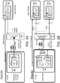
- the TDM-PON architectures include two wavelengths used to separate the upstream and downstream transmissions.
- 1310-nm wavelength is used for upstream transmission from the ONU 60 at the customer premise to the OLT 50 at the CO 40 and 1490-nm wavelength is used for the transmission from the OLT 50 at CO 40 to ONUs 60 at the user 30 premises.
- the upstream and downstream wavelengths are multiplexed on a single fiber 20, 22 with an optical wavelength diplexer 52 in front of the laser diode (LD) transmitter 54 and photo-detector (PD) receiver 56.
- the optical signal from the OLT 50 is split in the field with a 1: N power splitter 72 to broadcast the signal to multiple ONUs 60 serving different users 30.
- the distance between the OLT 50 and ONU 60 is limited by the OLT/ONU transmitter power and receiver sensitivity, as well as splitting loss.
- the OLT transceiver 50 is shared among the users 30 on the same power splitter 72 using a TDM protocol, simplifying the fiber termination at the CO 40 and spreading the cost of the transceivers 50 across multiple ONUs 60.
- Typical GPON and EPON designs use splitting ratios of 1:16, 1:32, or 1:64 and a transmission distance up to 20km.
- Wavelength division multiplexing (WDM) PON gives each user 30 a dedicated wavelength in each transmission direction.
- WDM-PON network each user 30 is allocated a different wavelength ⁇ for upstreaming data to the CO 40. Therefore, each ONU 60 uses a wavelength-specific transmitter 62, such as a tunable wavelength laser, to transmit data to the CO 40 at different wavelengths ⁇ .
- the tunable wavelength laser may be tuned at the time of deployment for each particular path 22 (corresponding to a user 30), which allows the use of one type of transceiver 60 by all users 30.
- the WDM-PON system provides a greater overall system capacity FTTH network because the total capacity is the channel capacity multiplied with the number of wavelengths used.
- each customer ONU 60 has a corresponding OLT 50 transmitter at the CO 40. Therefore, for 32 customers having 32 ONUs 60, the CO 40 has 32 OLTs 50 each sending a signal to an ONU 60.
- Signals from a CO 40 to individual ONUs 60 are carried using different wavelengths, and multiplexed in the fiber plant 20, 22 using a wavelength multiplexer 200, 200a, usually an Arrayed Waveguide Grating Router (AWG) in the field.
- AWG Arrayed Waveguide Grating Router
- Another wavelength multiplexer/demultiplexer 200, 200b inside the CO 40 separates the optical wavelengths in the feeder fiber 20 and connects them to individual 'colored' OLT transceivers 50, 50a-50n.
- the field AWG 200 is usually a cyclical device with multiple free spectral ranges (FSR) and the upstream and downstream wavelengths are separated by the FSR, as shown in FIGS. 3A-3C .
- FSR free spectral ranges
- both wavelength multiplexers 200 in the field and in the CO are cyclical AWGs.
- TWDM-PON time-wavelength division multiplexing PON
- NG-PON2 time-wavelength division multiplexing PON
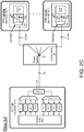
- the OLT 50 uses four downstream transmitter lasers (LD-1, LD-2, LD-3, LD-4) and four upstream receivers (PD-1, PD-2, PD-3, PD-4), combined with the diplexer 52 inside the OLT 50.
- NG-PON2 adopts a fiber plant 20 compatible with traditional TDM-PON, so all the four transmitting wavelengths in the OLT 50 are broadcast to each ONU 60, which has only one receiver 66. Consequently, the ONU 60 needs to use a tunable receiver 64 to select individual downstream wavelengths. At the same time, the ONU 60 is also equipped with a tunable transmitter 65 to tune to one of the four possible receiving wavelengths coming from an NG-PON2 OLT 50. Compared to the WDM-PON in FIG. 2B , where only the ONU transmitter 64 laser needs to be tunable (for inventory and easy operation), NG-PON2 ONU 60 needs to have both a tunable transmitter 65 laser and tunable receiver 66, translating to more expensive hardware.
- NG-PON2 must also overcome the extra loss of the power splitter 72, compared to the AWG 200 used in WDM-PON that inherently has less loss than power splitters for large port counts) and the tunable filter loss in the ONU 60.
- the aim of NG-PON2 was to increase the system capacity by increasing the TDM rate (10Gb/s per wavelength) and using multiple wavelengths to enable more users 30 and/or higher bandwidth applications. Nevertheless, the design faces power budget and cost challenges.
- Another challenge of NG-PON2 is that the OLT 50 and ONU 60 need to manage both wavelength slots and time slots; and requires new MAC layer protocol.
- the MAC software provides addressing and channel access control mechanisms allowing for several terminals or network nodes to communicate with each other within multiple access networks.
- a media access control is the hardware that implements the MAC.
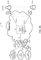
- an updated TWDM-PON architecture 100 shown in FIG. 3A with higher ONU count per feeder fiber 20 may accommodate the increase in bandwidth demand and take rate.
- the TWDM-PON architecture 100 (as shown and described with respect to FIGS. 3A-8 , 9B , and 10 ) combines the cost advantage of supporting multiple users 30 on a single wavelength (TDM-PON) with the wavelength flexibility of WDM-PON, which allows wavelengths to be dedicated to particular subscribers or applications.
- the upgraded TWDM-PON architecture 100 uses a combination of the TDM and WDM technologies ⁇ architectures described above (with respect to FIGS. 2A, 2B and 2C ) to multiply the number of users 30 and the capacity that may be supported on a single PON.
- the upgraded TWDM-PON 100 reduces the cost and construction time of fiber infrastructure and shortens the network design cycle.
- the upgraded TWDM-PON 100 provides for thinner fiber bundles 20, 22 to be used between the CO 40 and the RN 70, and between the RN 70 and the ONUs 60, which leads to smaller conduits that are easier to deploy.
- the upgraded TWDM-PON 100 increases the coverage distance, i.e., the length of the feeder fiber 20, 22 and enables super PON designs, which allow the upgraded TWDM-PON 100 to consolidating and reduce the number of COs 40 and reduces the long term recurring cost in network operation. Moreover, the upgraded TWDM-PON 100 does not require tunable receivers at the ONUs 60, which significantly decreases the cost of the network 100.
- the upgraded TWDM-PON 100 may achieve similar overall capacity per feed fiber shown in FIG. 2C (NG-PON2, 40Gbps) with 16 wavelengths and current GPON speed (2.5Gbps downstream and 1.25Gbps). In addition, the upgraded TWDM-PON 100 better scales with transmission distance over the feeder fiber 20, 22, and has better power budget and dispersion tolerance compared to NG-PON2.
- TDM-PONs use an optical power splitter 72 at the RN 70 to connect multiple ONUs 60 to each OLT 50.
- each ONU 60 includes a blocking filter to block out-of-band wavelengths.
- a tunable ONU 60 is used and includes a tunable narrow band filter. Use of a tunable ONU 60 increases the cost of each ONU 60, which leads to an increase in the cost of the network 100.
- the power splitter 72 at the RN 70 may not achieve large split ratios because the total power loss for a large splitter is difficult to overcome by the transmitters 54, 64 and receivers 56, 66, at the OLTs 50 and ONUs 60. Therefore, in the upgraded TWDM-PON architecture ( FIG. 3A ) it is desirable to use a wavelength selective (de)multiplexer, such as the cyclical arrayed waveguide grating router (AWG) 200 to greatly increases the maximum split ratio and remove the need for narrow-band filters at the ONUs 60, thereby reducing the cost (by not using tunable receivers). Additionally, the cyclical AWG 200 decouples the loss from the number of ports, thereby allowing a higher split ratio with lower loss. Multiple TDM PONs (e.g., 1G-PON and 10G-PON) using an AWG 200 may be thought of as a TWDM-PON, since WDM is utilized to increase overall capacity of the network.
- AWG cyclical arrayed waveguide
- FIGS. 3A- 3E illustrate an exemplary arrayed waveguide grating 200 (AWG) used in the upgraded TWDM-PON architecture 100.
- An AWG 200 may be used to demultiplex an optical signal in the upgraded TWDM-PON 100, for example at the RN 70 or at the OLT 50.
- AWGs 200 can multiplex a large number of wavelengths into one optical fiber, thus increasing the transmission capacity of optical networks 100.
- AWGs 200 can therefore multiplex channels of several wavelengths onto a single optical fiber at a transmission end, and reciprocally they can also demultiplex different wavelength channels at the receiving end of an optical communication network.
- An AWG 200 is a passive planar light wave circuit device typically used in optical networks as a wavelength multiplexer and/or demultiplexer.
- NxN AWGs 200 also have wavelength routing capabilities. If a system has N equally-spaced wavelengths ⁇ N , an NxN AWG 200 can be designed with an egress port spacing matching the wavelength spacing. The NxN AWG 200 routes differing wavelengths at an ingress port 210 to different egress ports 220 such that all N wavelengths are mapped to all N egress ports 220 N sequentially. The routing of the same N wavelengths at two consecutive ingress ports 210 have the wavelength mapping shifted by one egress side. In addition, the wavelength channels on any ingress repeat at the FSR. In some implementations, the AWG 200 receives a first multiplexed optical signal at a first input 210a (e.g., input 1) via a first optical fiber. The AWG 200 demultiplexes the received signal and outputs demultiplexed signals through its outputs 220, 220a-n (e.g., outputs 1-32).
- a first input 210a e.g., input 1
- the AWG 200 is cyclic in nature.
- the wavelength multiplexing and demultiplexing property of the AWG 200 repeats over periods of wavelengths called free spectral range (FSR). Multiple wavelengths, separated by the free spectral range (FSR), are passed down each port 220. Therefore, by utilizing multiple FSR cycles, different tiered services may coexist on the same fiber plant 20, 22.
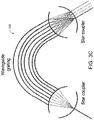
- the star couplers and the waveguide grating should be carefully designed.
- the arrayed waveguides in the fiber grating should be correctly engineered.
- the phase difference between waveguides in the grating is a factor that determines the FSR B1-B4 of the AWG 200.
- the channel-by-channel loss profile within one FSR B1-B4 is related with the overlap integral between the eigenmode (natural vibration of the AWG 200) of the output channel waveguide and beamlets diffracted from the waveguide arms in the grating.
- the end channels of any FSR B 1-B4 typically have a larger loss and compromised pass-band. It is usually optimal to design around four or six more channels than the desired number of channels, thereby wasting four or six channels of bandwidth per cycle, respectively.
- the disadvantage of using a cyclic AWG 200 with small FSR is that the channel spacing may vary slightly from cycle to cycle.
- the wavelength spacing, with respect to frequency, may be wider for shorter wavelengths.
- the waveguide arm phase difference, the material dispersion, i.e., the refractive index changing with wavelength, and waveguide cross-section design all contribute to the variation in channel spacing across FSRs.
- the channel spacing can be optimized by proper material choice and waveguide design, but it is very difficult to make a uniform frequency spacing across multiple FSRs.
- a larger AWG 200 is used in combination with splitters 72 (see, for example, FIG. 4 ).
- the AWG 200 may have multiple cycles of optical wavelengths ranges with repeating multiplexing and demultiplexing properties. As shown in FIG. 3C , each cycle B 1-B4 is often referred to as an FSR. A multi-cycle AWG 200 sends multiple wavelengths ⁇ 1 - ⁇ 16 , separated by the FSR, down each port 220, 220a-220d. In most PON systems, different wavelengths are used for upstream and downstream of signals due to the near-far-effect. The near-far effect is a condition where a receiver captures a strong signal and thereby making it impossible for the receiver to detect a weaker signal.
- a WDM-PON platform uses two FSR cycles of the cyclical AWG 200 (one cycle for downstream transmission and the other cycle for upstream transmission) for each tier of service.
- FFF thin-film filter
- a second platform uses two FSR cycles of the cyclical AWG 200 (one cycle for downstream transmission and the other cycle for upstream transmission) for each tier of service.
- four usable cycles would allow for the simultaneous use of two platforms.
- Such a system 100 would deliver signals from both platforms to each of the users 30, and each AWG output 220 would output/receive signals from both platforms.
- Each AWG output 220 is optically connected with at least one ONU 60, then each ONU 60 would receive signals from both platforms.
- FIG. 3C shows a cyclical AWG 200 having an input 210a and four outputs 220, 210a-220b.
- the cyclical AWG 200 receives four FSR (bands) B1-B4, as shown in FIG. 3D .
- FSRs B1 and B2 are used for upstream while FSRs B3 and B4 are used for downstream.
- FSR B1 includes wavelengths ⁇ 1 - ⁇ 4
- FSR B2 includes wavelengths ⁇ 5 - ⁇ 8
- FSR B3 includes wavelengths ⁇ 9 - ⁇ 12
- FSR B4 includes wavelengths ⁇ 13 - ⁇ 16 ; where ⁇ 1 ⁇ ⁇ 2 ⁇ ⁇ 3 ⁇ .... ⁇ ⁇ 15 ⁇ ⁇ 16 .
- the first wavelength ⁇ 1 of the first FSR B 1 is outputted through the first output 220a of the cyclical AWG 200
- the second wavelength ⁇ 2 of the first FSR B 1 is outputted through the second output 210b of the cyclical AWG 200
- the third wavelength ⁇ 3 of the first FSR B 1 is outputted through the third output 220c of the cyclical AWG 200
- the fourth wavelength ⁇ 4 of the first FSR B 1 is outputted through the fourth output 220b of the cyclical AWG 200, completing the first cycle.
- the second cycle begins when the first wavelength ⁇ 5 of the second FSR B2 is outputted through the first output 220a of the cyclical AWG 200, the second wavelength ⁇ 6 of the second FSR B2 is outputted through the second output 220b of the cyclical AWG 200, the third wavelength ⁇ 7 of the second FSR B2 is outputted through the third output 220c of the cyclical AWG 200, and the fourth wavelength ⁇ 8 of the second FSR B2 is outputted through the fourth output 220b of the cyclical AWG 200, completing the second cycle.
- the third cycle begins with the first wavelength ⁇ 9 of the third FSR B3 is outputted through the first output 220a of the cyclical AWG 200, the second wavelength ⁇ 10 of the third FSR B3 is outputted through the second output 220b of the cyclical AWG 200, the third wavelength ⁇ 11 of the third FSR B3 is outputted through the third output 220c of the cyclical AWG 200, and the fourth wavelength ⁇ 12 of the third FSR B3 is outputted through the fourth output 220b of the cyclical AWG 200, completing the third cycle.
- the fourth cycle begins with the first wavelength ⁇ 13 of the fourth FSR B4 is outputted through the first output 220a of the cyclical AWG 200, the second wavelength ⁇ 14 of the fourth FSR B4 is outputted through the second output 220b of the cyclical AWG 200, the third wavelength ⁇ 15 of the fourth FSR B4 3 is outputted through the third output 220c of the cyclical AWG 200, and the fourth wavelength ⁇ 46 of the fourth FSR B4 is outputted through the fourth output 220b of the cyclical AWG 200, completing the fourth cycle.
- each FSR B 1-B4 includes four wavelengths ⁇ 1 - ⁇ 16 (FSR B1 includes wavelengths ⁇ 1 - ⁇ 4 , FSR B2 includes wavelengths ⁇ 5 - ⁇ 8 , FSR B3 includes wavelengths ⁇ 9 - ⁇ 12 , FSR B4 includes wavelengths ⁇ 13 - ⁇ 16 ), and the cyclical AWG 200 includes four outputs 220. Therefore, one wavelength from each FSR B 1-B4 outputs each AWG output 220. In other words, each AWG output 220 outputs a wavelength from an FSR B 1-B4.
- a first platform may use the first FSR B 1 for upstreaming and the third FSR B3 for downstream, and the second platform may use the second FSR B2 for upstreaming and the fourth FSR B4 for downstream.
- the network 100 may support three platforms by using six FSR cycles providing three platforms to each user 30.
- the network may also provide four platforms by using eight FSR cycles, five platforms by using 10 FSR cycles, and so on.
- each wavelength ⁇ carries multiple users 30, therefore, the network 100 may be configured to operate different rates of PONs concurrently to serve different tiers of services (e.g., 1 G-PON and 10 G-PON).
- the service provider at the CO 40 may want to provide a business/premium service on a higher rate PON and standard residential services on a lower rate PON.
- the business/premium service may use one of the first and third FSRs B1, B3 or the second and fourth B2, B4, and the low rate PON may use the other one of the first and third FSRs B1, B3 or the second and fourth B2, B4.
- the service that the user 30 receives is determined by their respective ONU 60, which is part of the customer premises equipment (CPE).
- the CPE may be configured to receive one or the other of the business premium service or the low rate service.
- the user 30 wants to upgrade from the low rate service to the business/premium service, the user 30 has to change/upgrade his CPE to be able to receive the upgraded/premium signals that are being transmitted from the CO 40.
- FIG. 3E shows a system with only two FSRs B1, B2 of four wavelengths each ( ⁇ 1 - ⁇ 4 , and ⁇ 5 - ⁇ 8 ), totaling eight wavelengths.
- the uplink and downlink use the same wavelength.
- the signal at the ingress of the AWG 210 is carrying both uplink and downlink signals for eight different TDM-PONs on eight different wavelengths ( ⁇ 1 - ⁇ 4 , and ⁇ 5 - ⁇ 8 ).
- a cyclical AWG 200 with an FSR of four wavelengths is used at the RN 70, thus sending two TDM-PON services down each egress port of the AWG 220a-d.
- This system therefore works identical to the one shown in FIG. 3D , except wavelength selective technologies, such as TFF, cannot be used as the diplexer at either the OLT 50 or the ONU 60. Instead, a directional device, such as an optical circulator, must provide all of the required optical isolation between the input and output. A wavelength selective component would still be used at both the OLT 50 and ONU 60 to select the free spectral range. If such a technology were to become readily available in the future, after deployment of field AWGs capable of the wavelength plan described in FIG. 3D , it may be desirable to upgrade services to use the same wavelength for upstream and downstream, thus enabling up to four different services to each AWG egress port.
- FIG. 4 shows a schematic view of the high-level architecture of the TWDM network 100 from the CO 40 to the ONUs 60 associated with the end users 30.
- TDM-PON systems such as G-PON or E-PON, are commonly deployed commercial FTTH systems because of their cost and bandwidth efficiency. The systems typically use ratios such as 1:16, 1:32, and 1:64.
- increasing the split ratio decreases overall OLT cost and feeder fiber strands 20, 22 but also decreases the capacity and reach to each user 30, since larger splitters have a larger loss.
- a CO 40 of 20,000 passings with a 1:32 split ratio means a minimum of 625 fiber strands 20 must be used from the CO 40 to the RN 70.
- a very large CO 20 of 100,000 passings needs 3125 fibers 20.
- the larger service area means the average distance between the user 30 and the CO is greater, further increasing the required amount of fiber in the network.
- Such a large number of feeder fibers 20 makes large COs 40 unattractive because of the high fiber costs and, increased mean time to restore in the event of a fiber cut of a thick fiber cable 20.
- larger-sized conduits are used underground to house the thick fibers 20.
- thick cables mean heavy load on utility poles. Therefore, the upgraded TWDM-PON 100 reduces the number of feeder fibers 20, 22 from the CO 40 to service the same number of users 30 by combining both TDM and WDM with a scalable TWDM architecture. As shown in FIG.
- the upgraded TWDM-PON 100 includes multiple TDM-PONs stacked on a single feeder cable 20 using wavelength division multiplexing. Therefore, if 10 pairs of wavelengths (covered by two FSRs of a ten port cyclical AWG) are used, 10 TDM-PONs may be multiplexed onto a single feeder fiber 20, reducing the number of feeder fibers 20 needed from a CO 40 by ten times.
- an AWG 200 is used in the field to first separate out the wavelength pairs.
- Each output port 220 of the AWG 200 is followed by a power splitter 72 to split the TDM signal to individual ONUs 60, as in traditional TDM PONs ( FIG. 2A ).
- the total number of users 30 or ONUs 60 per feeder fiber 20 is MxN , where M is number of output port 220 of the WDM splitter (e.g., AWG 200) and N is the TDM power splitting ratio of the power splitter 72. Consequently, the number of fibers, conduit size and mean time to repair (MTTR) a fiber cut are reduced by a factor of M .
- M number of output port 220 of the WDM splitter (e.g., AWG 200)
- N is the TDM power splitting ratio of the power splitter 72. Consequently, the number of fibers, conduit size and mean time to repair (MTTR) a fiber cut are reduced by a factor of M .
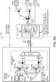
- FIG. 5A shows the upgraded TWDM architecture 100 using 1G-PON to represent TDM-PON.
- the G-PON wavelengths are shifted.
- "1G-PON ⁇ 1" at the CO 40 means a G-PON OLT 50 with modified optical layer, so that the G-PON OLT 50 transmits on wavelength ⁇ 1 of the upstream FSR B 1 of the cyclical AWG 200 and receives from the paired wavelength ⁇ 9 in the corresponding upstream FSR B3.
- the 1G-PON OLT 50 transmits on wavelength ⁇ 5 of the upstream FSR B2 of the cyclical AWG 200 and receives from the paired wavelength ⁇ 13 in the corresponding upstream FSR B4.
- the signal of each OLT is multiplexed with the signals of the other OLTs (e.g., optical system 300 that includes multiplexer 310, 320) before sending it to the remote node 70.
- FIG. 5A shows discrete OLT transceivers 50, which allow the TWDM system to piggyback onto a commercial G-PON OLT chassis. Therefore, to upgrade the network, and ISP switches the G-PON OLT transceivers with transceivers 50 designed at the custom wavelengths and inserts the multiplexers 310, 320 and amplifiers 330 (if needed).
- the discrete OLT transceivers 50 (as opposed to integrated array OLT transceivers used in a WDM-PON) allow for flexibility of using different protocols(e.g., G-PON and 10 G-PON), where each protocol is on a different wavelength (see FIG. 5B ).
- wavelength ⁇ 1,1 of the cyclical AWG 200 is used for 1G-PON protocol (OLTs 50aa), whereas wavelength ⁇ 2,1 is used for 10G-PON protocols (OLTs 50b). So the ONUs 60 hanging off power splitters 72 connected to ⁇ 1,1 of the AWG output port 220 are all tunable 1G-PON-ONUs 60 and ONUs 60 connected to ⁇ 2,1 of the AWG output port 220 are all tunable 10G-PON ONUs.
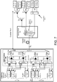
- an optical system 300 includes duplex fibers for separate transmitting (downstream signals S DM ) and receiving connections (upstream signals S UM ), which is different than the conventional G-PON OLT transceivers having a single fiber interface with a built in diplexer that separates upstream and downstream signals within the OLT 50.
- the optical system 300 includes a band multiplexer 310, a downstream multiplexer 320a for multiplexing signals from the OLT 50 (in L-Red band), and a demultiplexer 320b for demultiplexing signals received from the ONUs 60 (in C-Red band).
- the band multiplexer 310 acts as a diplexer since it multiplexes the upstream OLT signals S DM (in C-Red band) and the downstream OLT signals S DM (in L-Red band) into one transmit signal S T signal.
- the design of the optical system 300 uses a downstream multiplexer 320a to multiplex downstream signals S D1 -S Dn from one or more or OLTs 50 into one downstream signal S DM , and an upstream demultiplexer 320b for demultiplexing a multiplexed upstream signal S UM to one or more upstream signals S U1 -S Un to each OLT 50.
- the optical system 300 may include a signal booster 330 and/or a signal preamplifier 340 and the downstream and upstream directions respectively.
- the signal booster 330 and/or the signal amplifier 340 may be an Erbium-Doped Fiber amplifier (EDFA).
- EDFA is an optical repeater device that is used to boost the intensity of optical signals carried through feeder fiber.
- the EDFA signal booster 330 is optically connected with the downstream multiplexer 320a and the band multiplexer 310 and boosts the power of the multiplexed downstream signal S DM with a higher-power EDFA before entering into the long fiber feeder 20, or a device with large losses (e.g., power splitter) so it reaches the ONU 60.
- the EDFA signal amplifier 340 is optically connected with the upstream demultiplexer 320b and the band multiplexer 310 and boosts the power of the multiplexed upstream signal S UM .
- the EDFA signal amplifier 340 is positioned so that the multiplexed upstream signal S UM is amplified when it arrives at the optical system 300 as a weak signal.
- the EDFA signal booster 330 boosts the multiplexed downstream signal S DM that includes the signals S D1 -S Dn from multiple OLTs 50, and the EDFA signal amplifier 340 amplifies the multiplexed upstream signal S UM that includes the signals S U1 -S Un to multiple OLTs 50, then the cost of each EDFA 330, 340 is shared among all the TWDM wavelengths ⁇ , resulting in cost efficient upgraded TWDM-PON 100 architecture.
- the optical system 300 as described extends the reach of the feeder fiber 20 from the CO 40 to a range of 50 kilometers using a 1:32 way splitter 72.
- another set of EDFAs 330, 340 may be placed at the RN 70. However, placing EDFAs 330, 340 at the RN 70 changes the RN 70 from a passive RN 70 to a powered RN 70.
- the use of the EDFAs 330, 340 as part of the optical system 300 is optional and depends on the reach and size of the upgraded TWDM-PON 100. Moreover, the EDFAs relaxes the requirements of the OLT 50 and the ONU 60 transceivers, reducing the needed transmitter laser power and receiver sensitivity for both the ONU 60 and the OLT 50. With proper link designs, the shared-cost of the EDFAs improves transceiver yields and reduce the overall upgraded TWDM-PON 100 architecture costs.
- the ONUs 60 of the network 100 include tunable transmitter lasers.
- one or more output ports 220 of the AWG 200 may be optically connected with a power splitter 72 for conveying an output signal from the AWG 200 to multiple ONUs 60.
- Connecting power splitters 72 to the AWG 200 provides the upgraded TWDM-PON 100 with lower overall loss than using power splitters alone to achieve the splitting ratio and thus increases the scalability of the upgraded TWDM-PON 100.
- the ONU 60 may include a tunable laser; however, a non-tunable laser may also be used. Since each ONU 60 receives/transmits signals on a specific wavelength ⁇ , a laser is used to transmit a signal on the correct wavelength. Thus, the ISP may use multiple ONUs each having a different laser to accommodate for the different wavelengths received.
- the edge output ports 220a, 220b, 220m, 220n of the AWG 200 are connected to point to-point (pt-2-pt) WDM-PON transceivers at the ONUs 60.
- the transceivers 50 may be pt-2-pt WDM or TDM transceivers due to the ease of mixing wavelength specific TDM-PONs with pt-2-pt WDM-PONs on the same fiber plant 20.
- the upgraded TWDM-PON 100 may include 20 wavelengths.
- the ISP may reserve the center 16 wavelengths for TDM-PONs and the four edge wavelength channels, two each end of the AWG for pt-2-pt pure WDM transmissions (i.e., edge output ports 220a, 220b, 220m, 220n).
- the edge channels of an AWG 200 i.e., edge output ports 220a, 220b, 220m, 220n
- these channels i.e., edge output ports 220a, 220b, 220m, 220n
- the pt-2-pt WDM-PON channels may be used to carry premium services such as 10Gbps enterprise network connections that require guaranteed bandwidths.
- the ISP leverages the repeating FSRs B 1-B4 of the cyclical AWG 200 to update or expand the upgraded TWDM-PON 100.
- the upgraded TWDM-PON 100 may use the first FSR B1 (upstream FSR) and the third FSR B3 (downstream FSR) for the existing service(s), and the second FSR B2 (upstream FSR) and the fourth FSR B4 (downstream FSR) for the upgraded or expansion service(s). Or the upgraded TWDM-PON 100 may use the second FSR B2 (upstream FSR) and the fourth FSR B4 (downstream FSR) for the existing service(s), and the first FSR B1 (upstream FSR) and the third FSR B3 (downstream FSR) for the upgraded or expansion service(s).
- the FSRs B1-B4 are interleaved so that the upstream and downstream wavelengths are separated from each other, which eases the diplexer design inside the ONUs 60.
- Each ONU receiver (of the transceiver) is equipped with a band filter to select the desirable FSR B 1-B4 for the particular service of interests. Therefore, there is no need for a tunable receiver at the ONU 60.
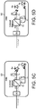
- each ONU 60 includes a diplexer 62, which multiplexes first and second ports P1, P2 of the diplexer into a third port P3.
- the signals on the first and second ports P1, P2 occupy disjoint frequency bands, i.e., are on different FSRs B1-B4; therefore, the signals on the first and second ports P1, P2 can coexist on the third port P3. Therefore, the two shorter wavelength bands FSR B1 and FSR B2 are used for uplink and the two longer wavelength bands FSR B3 and FSR B4 are used for downlink. This relaxes the requirements of the colored diplexer in the ONU 60.
- each ONU 60 includes the band-pass filter 64 before the diplexer 62 to remove unwanted downlink channels from OLTs 50 for other services.
- the fixed band-pass filter 64 passes frequencies or wavelengths ⁇ within a certain range and rejects (i.e., attenuates) frequencies or wavelengths ⁇ outside that range. Therefore, each band-pass filter 64 passes the desired wavelengths ⁇ associated with the desired service.
- the diplexer 62 inside each ONU 60 also serves as the band-pass filter 64 before the receiver Rx to remove unwanted downlink channels from OLTs 50 for other services.
- FIG. 5C shows an example ONU 60 that is configured to receive/transmit signals on the first and third FSRs B1, B3. While FIG. 5D shows an example ONU 60 configured to receive/transmit signals on the second and fourth FSRs B2, B4.
- the system 100 may include one or more optical splitter 72 in communication with each output 320 of the AWG 200.
- the optical splitter 72 further expands the network 100.
- Each optical splitter 72 conveys the signal outputted from each port 320 of the AWG 200 to the ONUs 60.
- the first signal having wavelength ⁇ 1 outputted from the first non-edge port 220c of the AWG 200 is split by the power splitter 72, then the first signal having wavelength ⁇ 1 is conveyed to the ONUs 60 that are optically connected with the splitter 72 transmitting the first signal having wavelength ⁇ 1 .
- the first ONU 60a which is an ONU using the G-PON MAC 60a receives the outputted signal having wavelength ⁇ 1 that is transmitted from the first OLT 60a.
- the second ONU 60k may be an ONU using the G-PON MAC 60k (as shown in FIG. 5A ) or a 10G-PON ONU 60a (as shown in FIG. 5B ) and receive/transmit a signal having wavelength ⁇ 2 from/to the second OLT 50ab, which is an OLT using the G-PON MAC (as shown in FIG. 5A ) or a 10G-PON OLT (as shown in FIG. 5B ).
- Each ONU 60a, 60k includes the band-pass filter 64 ( FIGS. 5C and 5D ) that filters the wavelengths that the ONU 60 may receive.
- Wavelength ⁇ n,m represents the n th wavelength of FSR m of the AWG port 220.
- wavelength ⁇ 1,1 represents the first wavelength ⁇ 1 of the first FSR B 1 for upstreaming (or third FSR B3 for downstreaming).
- Wavelength ⁇ 2,1 represents the second wavelength ⁇ 2 of the first FSR B 1 for upstreaming (or third FSR B3 for downstreaming).
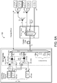
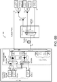
- FIG. 6A shows a TWDM network 100 similar to FIG. 5A with two OLTs using the G-PON MAC 50aa, 50ab; while FIG. 6B shows a TWDM network 100 similar to FIG. 5B with an OLT using the G-PON MAC 50aa and a 10G-PON OLT 50ab.
- the ISP overlays the new upgraded or expanded OLTs 50, 50ba-50bn on the expansion FSRs B2, B4 first. Then the end users 30 may swap their legacy ONUs 60 with upgraded ONUs 60 configured to receive the updated signals from the expansion FSRs B2, B4. After all the legacy ONUs 60 have been swapped out with the new upgraded ONUs 60, the legacy OLTs 50, 50aa-50an may be decommissioned, making the FSRs they originally occupy (e.g., FSR B1 and FSR B2) available for upgrading to yet newer services. As shown, the legacy system uses FSRs B1 and B3 and the expanded or upgraded system uses FSRs B2 and B4; however, the legacy system may use FSRs B2 and B4 and the expanded or upgraded system uses FSRs B1 and B3.
- the legacy system uses FSRs B1 and B3 and the expanded or upgraded system uses FSRs B2 and B4; however, the legacy system may use FSRs B2 and B4 and the expanded or upgraded system uses
- the optical system 300 of FIG. 7 additionally includes a downstream multiplexer 320c for multiplexing signals from the OLT 50 (in L-Blue band), and a demultiplexer 320d for demultiplexing signals received from the ONUs 60 (in C-Blue band).
- the band multiplexer 310 multiplexes the upstream OLT signals S DM (in C-Red band and C-Blue band) and the downstream OLT signals S DM (in L-Red band and L-Blue band) into one transmit signal S T signal.
- the design of the optical system 300 uses a downstream multiplexer 320c to multiplex downstream signals S D1 -S Dn from one or more or OLTs 50ba-50bn into one downstream signal S DM , and an upstream demultiplexer 320d for demultiplexing a multiplexed upstream signal S UM to one or more upstream signals S U1 -S Un to each OLT 50ba-50bn.
- the optical system 300 may include a second signal booster 330b and/or a second signal preamplifier 340b in the downstream and upstream directions respectively in addition to the first signal booster 330a and/or a first signal preamplifier 340a, similar to the ones described above.
- the use of the EDFAs 330b, 340b as part of the optical system 300 is optional and depends on the reach and size of the upgraded TWDM-PON 100.
- the additional pair of FSRs B2, B4 allows two upgraded services to co-exist over the same fiber plant 20, 10G-PON and 100G pt-2pt, for example.
- 1G-PON and 10G pt-2-pt services are serviced through the first and third FSRs B1, B3 of the cyclical AWG 200 whereas 10G-PON and 100G pt-2-pt services are serviced through second and fourth FSRs B2, B4 of the cyclical AWG 200.
- each splitter may be connected to a 1G-PON ONU or 10G-PON ONU, and each pt-2-pt link can be either a 10G link or 100G link.
- the ONUs 60 use tunable lasers with the right tuning range for upstream transmission and built in band filters in front of receivers to select the correct service wavelengths.
- the service each user receives is therefore controlled completely by the ONU hardware.
- WDM band mux filters 74 are used to separate pt-2-pt services overlaid on the same AWG output port.
- the upgraded TWDM-PON 100 uses the C-band and L-band for upstream and downstream transmissions respectively.
- Each of the C-band and L-band is further segregated into two FSRs B1-B4, Blue (short wavelengths) and Red (long wavelengths).
- the number of wavelengths in each FSR depends on the channel spacing. For 100GHz spaced wavelengths, each FSR can support roughly 20 wavelengths.
- the legacy OLTs 50aa-50an using FSR B1 and B3 use the short wavelengths (i.e., blue) of each of the C-band and L-band ( FIG. 8A ).
- the legacy OLTs 50aa-50an using FSR B1 and B3 use the short wavelengths (i.e., blue) of each of the C-band and L-band ( FIG. 8A ).
- FIG. 8A the legacy OLTs 50aa-50an using FSR B1 and B3 use the short wavelengths (i.e., blue) of each of the C-band and L-band
- the legacy OLTs 50aa use the long wavelength (i.e., red) and the expanded or updated system uses the short wavelength (i.e., red).
- C-band and L-band wavelengths for the WDM-PON and TWDM-PON provide for the lowest loss of glass fiber, thus providing for the longer distances of transmission and use of lower power transmissions.
- C-band and L-band are easily amplified EDFAs, which are the most mature fiber optic technology. This allows implementation with longer transmission distances and super-sized COs.
- DWDM eco system already exists in the C-band and L-band, and it is easy to get WDM and tunable lasers in C-band and L-band.
- FIGS. 9A and 9B show a comparison of the current TDM architecture and the upgraded TWDM architecture 100
- the system of FIG. 9A shows ranches of fiber cables in a typical fiber plant.
- the size of the fiber bundle becomes smaller and smaller as fiber gets closer and closer to end user ONUs 60.
- This figure represents that larger-size conduits are used for thicker cables, which are closer to the CO 40.
- small size conduits are used for the upgraded TWDM-PON 100.
- a standard one size conduit may be used for all the construction, simplifying the upgraded TWDM-PON 100 design.
- the upgraded TWDM-PON 100 design allows for the use of fewer COs 40 since each CO 40 can serve more ONUs.
- the centralization of the COs 40 simplifies the upgraded TWDM-PON 100 operation and saves recurring operating costs as fewer active COs and hence less staff is required to manage and operate the network.
- the fiber cables 20, 22 go through branches to serve different areas. As illustrated in FIG. 9A , a typical network starts with a very wide trunk and the branches 22 become thinner and thinner, which also reduces the required conduit size. Larger conduits are slower and more expensive to construct than thinner conduits. In fact, the reduction in the size of the feeder fiber 20, 22 is significant enough that a single size conduit could be used throughout the upgraded TWDM-PON 100 from the CO 40 to end users 30. This not only reduces the cost and time of fiber plant 20, 22 construction, but also simplifies upgraded TWDM-PON 100 design (so that only route design is needed and there is no need to worry about conduit size). The speed of network design and the permitting process could also be improved.
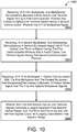
- a method 1000 for upgrading/expanding an upgraded TWDM network 100 includes at block 1002, receiving, at a first multiplexer (MUX) 320a, and multiplexing/demultiplexing between: a first multiplexed signal S DM ; and a first optical line terminal signal S D1 having a first multiplexing group (TDM-PON) and a second optical line terminal signal S Dn having a second multiplexing group (pt-2-pt).
- MUX multiplexer
- the method 1000 includes receiving, at a second multiplexer 320b, and multiplexing/demultiplexing between: a second multiplexed signal S UM ; and a third optical line terminal signal S U1 having the first multiplexing group (TDM-PON) and a fourth optical line terminal signal S Un having the second multiplexing group (pt-2-pt).
- the method 1000 includes receiving, at a third multiplexer 310 (e.g., BAND MUX) optically connected with the first multiplexer 320a and the second multiplexer 320b, and multiplexing/demultiplexing between: a feeder optical signal S Ta ; and the first and second multiplexed signals S DM , S UM .
- a third multiplexer 310 e.g., BAND MUX
- the first optical line terminal signal S D1 (TDM-PON, ⁇ 1 ) and the second optical line terminal signal S Dn (pt-2-pt) each includes a wavelength in a legacy downstream free spectral range FSR B3 or FSR B4, and the third and fourth optical line terminal signals S U1 , S Un each include a wavelength in a legacy upstream free spectral range FSR B 1 or FSR B2.
- the method 1000 may further include amplifying, at a first amplifier 330a optically connected with the first multiplexer 320a and the third multiplexer 310 (BAND MUX), the first multiplexed signal S DM ; or amplifying, at a second amplifier 340b optically connected with the second multiplexer 320b and the third multiplexer 310 (BAND MUX), the second multiplexed signal S UM .
- the first multiplexing group includes a TDM-PON protocol and the second multiplexing group (pt-2-pt) includes a WDM-PON protocol.
- the first optical line terminal signal S D1 and the third optical line terminal signal S U1 may each have a first protocol (TDM-PON, ⁇ 1 e.g., 1G-PON), and the second optical line terminal signal S Dn and the fourth optical line terminal signal S Un may each have a second protocol (10G pt-2-pt) different from the first protocol.
- the method 1000 further includes receiving, at the first multiplexer 320a (MUX), and multiplexing/demultiplexing between: the first multiplexed signal S DM ; and a fifth optical line terminal signal S D2 (TDM-PON, ⁇ 2,1 ), the first optical line terminal signal S D1 (TDM-PON, ⁇ 1,1 ), and the second optical line terminal signal S Dn (pt-2-pt).
- MUX multiplexer 320a
- MUX multiplexing/demultiplexing between: the first multiplexed signal S DM ; and a fifth optical line terminal signal S D2 (TDM-PON, ⁇ 2,1 ), the first optical line terminal signal S D1 (TDM-PON, ⁇ 1,1 ), and the second optical line terminal signal S Dn (pt-2-pt).
- the first optical line terminal signal S D1 has a first protocol (TDM-PON, ⁇ 1,1 , e.g., 1G-PON), and the fifth optical line terminal signal S D2 (TDM-PON 1 ) has the first multiplexing group (TDM-PON) and a second protocol (TDM-PON ⁇ 2,1 , e.g., 10G-PON) different from the first protocol (TDM-PON, ⁇ 1,1 , e.g., 1G-PON).
- the method 1000 also includes receiving, at the second multiplexer 320b, and multiplexing/demultiplexing between: the second multiplexed signal S UM ; and the second optical line terminal signal S DN , the fourth optical line terminal signal S U2 (pt-2-pt), and a sixth optical line terminal signal S U2 (TDM-PON).
- the sixth optical line terminal signal S U2 has the first multiplexing group (TDM-PON) and the second protocol (TDM-PON ⁇ 2,1 ), as shown in FIG. 6B ..
- the method 1000 may also include transmitting, by way of a feeder optical fiber 20 optically connected with the third multiplexer 310 (BAND MUX), the feeder optical signal S Ta .
- the method 1000 also includes receiving, at an AWG 200 optically connected with the feeder optical fiber 20, and multiplexing/demultiplexing between the feeder optical signal S Ta and optical network unit signals 50 1 -50 n .
- Each optical network unit signal 50 1 -50 n includes an upstream wavelength in the legacy upstream free spectral range FSR 1 or FSR 2 and a downstream wavelength in the legacy downstream free spectral range FSR 3 or FSR 4.
- the method 1000 includes receiving, at a fourth multiplexer 320c (MUX) optically connected with the third multiplexer 310, and multiplexing/demultiplexing between: a third multiplexed signal S Dm+ ; and a fifth optical line terminal signal S D1 having the first multiplexing group (TDM-PON) and a sixth optical line terminal signal S Dn having the second multiplexing group (pt-2-pt).
- MUX fourth multiplexer 320c
- the method 1000 also includes receiving, at a fifth multiplexer 320d optically connected with the third multiplexer 310, and multiplexing/demultiplexing between: a fourth multiplexed signal S UM+ ; and a seventh optical line terminal signal S U1 having the first multiplexing group (TDM-PON) and an eighth optical line terminal signal S Un having the second multiplexing group (pt-2-pt).
- the fifth optical line terminal signal S D2 and the sixth optical line terminal signal S Dn each has wavelengths in an upgrade upstream free spectral range FSR 1 or FSR 2, and the seventh (TDM-PON) and eight optical line terminal signals S U1 , S Un (pt-2-pt) each have wavelengths in an upgrade downstream free spectral range FSR 3 or FSR 4.
- the method 1000 may further include transmitting, by way of a feeder optical fiber 20 optically connected with the third multiplexer 310 (BAND MUX), the feeder optical signal S T a.
- the method 1000 also includes receiving, at an AWG 200 optically connected with the feeder optical fiber 20, and multiplexing/demultiplex between the feeder optical signal S Ta and optical network unit signals 50 1 -50 n .
- Each optical network unit signal 50 1 -50 n includes a legacy upstream wavelength in the legacy upstream free spectral range FSR 1 or FSR 2, a legacy downstream wavelength in the legacy downstream free spectral range FSR 3 or FSR 4, an upgrade upstream wavelength in the upgrade upstream free spectral range, and an upgrade second downstream wavelength in the upgrade downstream free spectral range.
Landscapes
- Engineering & Computer Science (AREA)
- Computer Networks & Wireless Communication (AREA)
- Signal Processing (AREA)
- Physics & Mathematics (AREA)
- Electromagnetism (AREA)
- Optical Communication System (AREA)
Abstract
Description
- This disclosure relates to Time-Wavelength-Division Passive Optical Network (TWDM-PON) architecture with extended reach and capacity.
- A basic communication system includes a transmitter that converts a message to an electrical form suitable to be transferred over a communication channel. The communication channel transfers the message from the transmitter to the receiver. The receiver receives the message and converts it back to its original form.
- Fiber optic communication is an emerging method of transmitting information from a source (transmitter) to a destination (receiver) using optical fibers as the communication channel. Optical fibers are flexible, transparent media made of thin glass silica or plastic that transmits light throughout the length of the fiber between the source and the destination. Fiber optic communications allow for the transmission of data over longer distances and at higher bandwidth than other known forms of communications. Fiber optics are an improved form of communication over metal wires because the light traveled through the fiber experiences less loss and is immune to electromagnetic interference. Companies use optical fibers to transmit telephone signals, internet communication, and cable television signals. A fiber-to-the-home (FTTH) network or fiber access network connects the end users using optical fiber as the last mile connection from the service provider.
- Fiber-optic communication provides a very low loss of signal and very high-bandwidth. These two properties allow service providers to directly connect to end-users from their central office (CO) using a passive fiber plant, which produces capital and operational cost savings. As demand for bandwidth in today's Internet continues to increase, as Fiber-to-the-home (FTTH) networks have become a good future proof technology for carriers to wire and rewire customers.
- In an access network, upgrading from one technology to another or improving the network architecture may be difficult due to updates in hardware at a central office (CO) and at optical network units (ONUs) located at customer premises. Each optical line terminal (OLT) in the CO serves one ONU in WDM networks and multiple ONUs in TDM networks. Therefore, upgrading the access network may be challenging due to timing of hardware upgrades at the ONUs. This disclosure provides a system and method of upgrading and expanding an access network to an upgraded/expanded architecture that allows efficient use of feeder fibers, therefore saving cost. The new architecture allows consolidations of COs with other PON networks (e.g., super-PON), reducing the operation cost and the network management efficiency.
- One aspect of the disclosure provides a communication system that includes first, second, and third multiplexers. The first multiplexer (e.g., MUX) is configured to multiplex a first optical line terminal signal having a first multiplexing group (e.g., TDM) and a second optical line terminal signal having a second multiplexing group into a first multiplexed signal. The second multiplexer (e.g., DEMUX) is configured to demultiplex a second multiplexed signal into a third optical line terminal signal having the first multiplexing group and a fourth optical line terminal signal having the second multiplexing group. The third multiplexer is optically connected with the first multiplexer and the second multiplexer. The third multiplexer is configured to multiplex/demultiplex between a feeder optical signal and the first and second multiplexed signals. The first and second optical line terminal signals each includes a wavelength in the legacy downstream free spectral range. In addition, the third and fourth optical line terminal signals each includes an upstream wavelength each in the legacy upstream free spectral range.
- Implementations of the disclosure may include one or more of the following optional features. In some implementations, the system further includes at least one of a first amplifier or a second amplifier. The first amplifier is optically connected with the first multiplexer (MUX) and the third multiplexer (BAND MUX) and is configured to optically amplify the first multiplexed signal. The second amplifier is optically connected with the second multiplexer (DEMUX) and the third multiplexer (BAND MUX) and is configured to optically amplify the second multiplexed signal. In some examples, the first multiplexing group includes a time-division-multiplexing passive optical network (TDM-PON) protocol and the second multiplexing group includes a wavelength-division-multiplexing passive optical network (WDM-PON) protocol, where each wavelength is a point-to-point link. The first optical line terminal signal and the third optical line terminal signal may each have a first protocol. Moreover, the second optical line terminal signal and the fourth optical line terminal signal may each have a second protocol different from the first protocol.
- In some implementations, the system further includes a first optical line terminal and a second optical line terminal. The first optical line terminal has an output optically connected with the first multiplexer and an input in optically connected with the second multiplexer. The first optical line terminal transmits the first optical line terminal signal and receives the third optical line terminal signal. The second optical line terminal has an output optically connected with the first multiplexer and an input optically connected with the second multiplexer. The second optical line terminal transmits the second (pt-2-pt) optical line terminal signal and receives the fourth (pt-2-pt) optical line terminal signal.
- The first multiplexer is further configured to multiplex a fifth optical line terminal signal with the first and second optical line terminal signals into the first multiplexed signal. The first optical line terminal signal may have a first protocol. The fifth optical line terminal signal may have the first multiplexing group (TDM-PON) and a second protocol different from the first protocol. The second multiplexer is further configured to demultiplex the second multiplexed signal into the second optical line terminal signal, the fourth optical line terminal signal (pt-2-pt), and a sixth optical line terminal signal. The sixth optical line terminal signal has the first multiplexing group and the second protocol. The system further includes a third line terminal that has an output in communication with the first multiplexer and an input in communication with the second multiplexer. The third optical line terminal transmits the fifth optical line terminal signal and receives the sixth optical line terminal signal.
- In some implementations, the system further includes a feeder optical fiber and an arrayed waveguide grating. The feeder optical fiber is optically connected with the third multiplexer and arranged to convey the feeder optical signal. The arrayed waveguide grating is optically connected with the feeder optical fiber and is configured to multiplex/demultiplex between the feeder optical signal and optical network unit signals. Each optical network unit signal includes an upstream wavelength in the legacy upstream free spectral range and a downstream wavelength in the legacy downstream free spectral range.
- The system may further include a fourth multiplexer and a fifth multiplexer. The fourth multiplexer is optically connected with the third multiplexer and is configured to multiplex a fifth optical line terminal signal having the first multiplexing group and a sixth optical line terminal signal (pt-2-pt) having the second multiplexing group into a third multiplexed signal. The fifth multiplexer is optically connected with the third multiplexer and configured to demultiplex a fourth multiplexed signal into a seventh optical line terminal signal having the first multiplexing group and an eighth optical line terminal signal (pt-2-pt) having the second multiplexing group. The fifth and sixth (pt-2-pt) optical line terminal signals each includes a downstream wavelength in the upgrade downstream free spectral range, and the seventh (TDM PON) and eight (pt-2-pt) optical line terminal signals each includes an upgrade upstream wavelength in the upstream free spectral range. The system may further include a feeder optical fiber and an arrayed waveguide grating. The feeder optical fiber is optically connected with the third multiplexer and arranged to convey the feeder optical signal. The arrayed waveguide grating is optically connected with the feeder optical fiber and configured to multiplex/demultiplex between the feeder optical signal and optical network unit signals. Each optical network unit signal includes a legacy upstream wavelength in the legacy upstream free spectral range, a legacy downstream wavelength in the legacy downstream free spectral range, an upgrade upstream wavelength in the upgrade upstream free spectral range, and an upgrade second downstream wavelength in the upgrade downstream free spectral range. The system may further include at least one of a first amplifier or a second amplifier. The first amplifier is optically connected with the fourth multiplexer and the third multiplexer and configured to optically amplify the third multiplexed signal. The second amplifier is optically connected with the fifth multiplexer and the third multiplexer and configured to optically amplify the fourth multiplexed signal. In some examples, the system also includes a third optical line terminal and a fourth optical line terminal. The third optical line terminal has an output in communication with the fourth multiplexer and an input in communication with the fifth multiplexer. The third optical line terminal transmits the fifth optical line terminal signal and receives the seventh TDM-PON optical line terminal signal. The fourth optical line terminal having an output in communication with the fourth multiplexer and an input in communication with the fifth multiplexer, the fourth optical line terminal transmitting the sixth (pt-2-pt) optical line terminal signal and receiving the eighth (pt-2-pt) optical line terminal signal.
- Another aspect of the disclosure provides a method that includes receiving, at a first multiplexer (MUX), and multiplexing/demultiplexing between: a first multiplexed signal; and a first optical line terminal signal having a first multiplexing group and a second optical line terminal signal (pt-2-pt) having a second multiplexing group. The method also includes receiving, at a second multiplexer, and multiplexing/demultiplexing between: a second multiplexed signal; and a third optical line terminal signal having the first multiplexing group and a fourth optical line terminal signal having the second multiplexing group. The method also includes receiving, at a third multiplexer optically connected with the first multiplexer and the second multiplexer, and multiplexing/demultiplexing between: a feeder optical signal; and the first and second multiplexed signals. The first and second optical line terminal signals each include a downstream wavelength in the legacy downstream free spectral range, and the third and fourth optical line terminal signals each include an upstream wavelength each in the legacy upstream free spectral range.
- This aspect may include one or more of the following optional features. In some implementations, the method further includes amplifying, at a first amplifier optically connected with the first multiplexer and the third multiplexer, the first multiplexed signal; or amplifying, at a second amplifier optically connected with the second multiplexer and the third multiplexer, the second multiplexed signal.
- In some examples, the first multiplexing group includes a time-division-multiplexing passive optical network protocol and the second multiplexing group includes a wavelength-division-multiplexing (WDM) passive optical network protocol, where each wavelength is a point-to-point link. The first optical line terminal signal and the third optical line terminal signal may each have a first protocol, and the second optical line terminal signal and the fourth optical line terminal signal may each have a second protocol different from the first protocol.
- In some implementations, the method further includes receiving, at the first multiplexer (MUX), and multiplexing/demultiplexing between: the first multiplexed signal; and a fifth optical line terminal signal, the first optical line terminal signal, and the second optical line terminal signal. The first optical line terminal signal has a first protocol, and the fifth optical line terminal signal (TDM-PON, λ2) has the first multiplexing group and a second protocol different from the first protocol. The method also includes receiving, at the second multiplexer, and multiplexing/demultiplexing between: the second multiplexed signal; and the second optical line terminal signal, the fourth optical line terminal signal, and a sixth optical line terminal signal (TDM-PON λ2). The sixth optical line terminal signal has the first multiplexing group and the second protocol.
- The method may also include transmitting, by way of a feeder optical fiber optically connected with the third multiplexer, the feeder optical signal. The method also includes receiving, at an arrayed waveguide grating optically connected with the feeder optical fiber, and multiplexing/demultiplex between the feeder optical signal and optical network unit signals. Each optical network unit signal includes an upstream wavelength in the legacy upstream free spectral range and a downstream wavelength in the legacy downstream free spectral range.
- In some implementations, the method includes receiving, at a fourth multiplexer optically connected with the third multiplexer, and multiplexing/demultiplexing between: a third multiplexed signal; and a fifth optical line terminal signal having the first multiplexing group and a sixth optical line terminal signal having the second multiplexing group. The method also includes receiving, at a fifth multiplexer optically connected with the third multiplexer, and multiplexing/demultiplexing between: a fourth multiplexed signal; and a seventh optical line terminal signal having the first multiplexing group and an eighth optical line terminal signal (pt-2-pt) having the second multiplexing group. The fifth and sixth optical line terminal signals each includes a downstream wavelength in the upgrade downstream free spectral range, and the seventh and eight optical line terminal signals each include an upstream wavelength in the upgrade upstream free spectral range. The method may further include transmitting, by way of a feeder optical fiber optically connected with the third multiplexer, the feeder optical signal. The method also includes receiving, at an arrayed waveguide grating optically connected with the feeder optical fiber, and multiplexing/demultiplex between the feeder optical signal and optical network unit signals. Each optical network unit signal includes a legacy upstream wavelength in the legacy upstream free spectral range, a legacy downstream wavelength in the legacy downstream free spectral range, an upgrade upstream wavelength in the upgrade upstream free spectral range, and an upgrade downstream wavelength in the upgrade downstream free spectral range.
- The details of one or more implementations of the disclosure are set forth in the accompanying drawings and the description below. Other aspects, features, and advantages will be apparent from the description and drawings, and from the claims.
-
-
FIG. 1 is a schematic view of a prior art PON architecture. -
FIG. 2A is a schematic view of a prior art TDM-PON architecture. -
FIG. 2B is a schematic view of a prior art WDM-PON architecture. -
FIG. 2C is a schematic view of a prior art NG-PON2 architecture. -
FIG. 3A is a schematic view of an example TWDM-PON architecture. -
FIGS. 3B and3C are schematic views of example arrayed waveguide gratings (AWGs). -
FIG. 3D is a schematic view of the cyclical behavior of the example AWG ofFIGS. 2A and 2B . -
FIG. 3E is a schematic view of a cyclical behavior of the example AWG ofFIGS. 2A and 2B , where the uplink and downlinks use the same wavelength. -
FIG. 4 is a schematic view of an example TWDM-PON architecture with a two-tier service. -
FIGS. 5A and5B are schematic views of example TWDM-PON architecture. -
FIGS. 5C and 5D are schematic views of an example ONUs used in the TWDM-PON architecture ofFIGS. 5A and5B . -
FIGS. 6A and6B are schematic views of an example TWDM-PON architecture configured to be upgraded/expanded. -
FIG. 7 is a schematic view of an example expanded/upgraded TWDM-PON architecture. -
FIG. 8A and 8B are schematic views of example spectrum allocations for the expanded/upgraded TWDM-PON architecture. -
FIG. 9A is an example schematic view of a prior art TDM-PON network. -
FIG. 9B is an example schematic view of an example TWDM-PON network. -
FIG. 10 is an example arrangement of operations for a method of upgrading/expanding a legacy network. - Like reference symbols in the various drawings indicate like elements.
- Fiber-to-the-home (FTTH) is the delivery of a communication signal through optical fibers from a central office (CO) or optical line terminal (OLT) to a home or a business of a user. Referring to
FIG. 1 , today's FTTH systems are mostly offered through point-to-multi-point time division multiplexed (TDM) passive optical networks (PONs) using a passive optical power splitter at a remote node 70 (RN) in the field to share a common transceiver 50 (OLT) at theCO 40, or through point-to-point (pt-2-pt) direct connection, where a home-run fiber extends all the way back to theCO 40 and each customer is terminated by a separate transceiver, as opposed to the shared transceiver (TDM transceiver).PON 10 provides optical signals from aCO 40 and includes an optical transmitter/receiver ortransceiver 50 to a number of optical network terminals (ONUs) 60 on customer premises that each includes a bidirectional optical transceiver. - Compared to pt-2-pt home run systems, a TDM-PON provides beneficial savings in the number of feeder fibers 20 (between a
remote node 70 and the central office 40), and in the number ofoptical transceivers 50 at theCO 40 while saving patch panel space to terminate fibers. However, TDM-PON does not scale well with bandwidth growth. The bandwidth per household is often oversubscribed, since the bandwidth per optical line terminal transceiver at thecentral office 40 is shared among allONUs 60 that are connected to anOLT 50. - Pt-2-pt systems provide high bandwidth to end users 30; however, pt-2-pt uses a great number of both
trunk fibers 20 andoptical transceivers 50. Thus, pt-2-pt systems do not scale well with theOLT 50 at theCO 40 and the fiber count between theCO 40 and theRN 70, resulting in greater space requirements, higher power, and an increased cost. - Fiber to the home (FTTH) is regarded as the end state of broadband access networks as fiber offers virtually unlimited bandwidth. FTTH replaces currently used copper infrastructure (e.g., telephone wires, coaxial cable, etc.). Multiplexing is a method used in optical networks to utilize the large bandwidth of optics to their full benefits. Multiplexing enables several virtual channels to be formed on a single fiber. Therefore, multiplexing several optical signals increases the utility of a network infrastructure. Time division multiplexing (TDM) is a method used to multiplex several signals onto one high-speed digital signal on a fiber optic link. TDM multiplexes several signals by establishing different virtual channels using different time slots. Wavelength division multiplexing (WDM) multiplexes the signals by having different channels use different wavelengths; these channels are generated by separate lasers and their traffic typically does not interact.
- With continued reference to
FIG. 1 , theCO 40 receives information, such asvideo media distribution 42, internet data 44, andvoice data 46 that may be transferred to the end users 30. TheCO 40 includes an optical line terminal (OLT) 50 connecting the optical access network to an IP, ATM, or SONET backbone, for example. Therefore, theOLT 50 is the endpoint of thePON 10 and converts the electrical signals used by a service provider's equipment and the fiber optic signals used by thePON 10. In addition, theOLT 50 coordinates multiplexing between the conversion devices at the user end 30. TheOLT 50 sends the fiber optic signal through afeeder fiber 20, and the signal is received by a passiveremote node 70, which distributes the signal to multiple users 30. In some examples, eachCO 40 includesmultiple OLTs 50, 50a-n. EachOLT 50 is configured to provide a signal to a group of users 30. In addition, eachOLT 50 may be configured to provide signal or services that are in different transmission protocols, e.g., one OLT provides services in 1G-PON and another provides services in 10G-PON (as will be discussed later). - A multiplexer (MUX) combines several input signals and outputs a combined signal of the separate signals. The multiplexed signal is transmitted through a physical wire, e.g., single
optical fiber 20, which saves the cost of having multiple wires for each signal. As shown inFIG. 1 , theCO 40 multiplexes the signals received from several sources, such asvideo media distribution 42, internet data 44, andvoice data 46, and multiplexes the received signals into one multiplexed signal before sending the multiplexed signal to theremote node 70 through thefeeder fiber 20. In addition, theCO 40 multiplexes the signals of eachOLT 50 before sending the multiplexed signal to the remote node set through thefeeder fiber 20. TheCO 40 includes a carrier source (e.g., a laser diode or a light emitting diode) for generating an optical signal that carries the multiplexed signal to the end user 30. On the receiver end, i.e., theONU 60 at the user end, a reverse process occurs using a demultiplexer. The demultiplexer receives the multiplexed signal and divides it into the separate original signals that were originally combined. In some examples, a photodetector converts the optical wave back into its electric form and is located at the remote node or at the end user 30 (e.g., data over a network, sound waves converted into currents using microphones and back to its original physical form using speakers, converting images converted into currents using video cameras and converting back to its physical form using a television). In TDM PONs, the demultiplexing of the signal occurs after the photodiode in the electrical domain. - A transceiver or
ONU 60, on the user end, includes a carrier source (e.g., laser diode or light-emitting diode) for generating an optical signal that carries the information to be sent from an end user 30 to theCO 40. A laser is a high-frequency generator or oscillator, which requires amplification, feedback, and a tuning mechanism that determines the frequency. Lasers emit light coherently such that the laser output is a narrow beam of light. In some implementations, a laser includes a medium that provides the amplification and the frequency, and mirrors that provide the feedback. Photons bounce off one mirror through the medium and head back to another mirror to bounce back for further amplification. One, and sometimes both mirrors, may partially transmit light to allow a fraction of the generated light to be emitted. A laser diode is an electrically pumped semiconductor laser having an active medium being a p-n junction. The p-n junction is created by doping (i.e., introduction of impurities into a pure semiconductor to change its electrical properties). As shown, onefeeder fiber 20 is employed from theCO 40 to aremote node 70, where the signal is split and distributed to, for example, optical network units 60a-60n. - Referring to
FIG. 2A , the most commonly deployed TDM-PON systems are the GPON systems standardized by ITU (International Telecommunication Union) and the EPON system standardized by IEEE (Institute of Electrical and Electronics Engineers). A GPON system offers 2.5 Gb/s downstream bandwidth and 1.25Gb/s upstream bandwidths, shared on thefeeder fiber 10 among the users 30, and connected to thesame OLT transceiver 50. GPON systems are mature and very cost effective. TDM PON faces difficulty in bandwidth scaling as the optical transceivers of both theOLT 50 and theONU 60 ends need to operate at the aggregate bandwidth of all of theONUs 60 sharing thesame OLT 40. TDM-PONs typically may have a 1:16 to 1:64 power splitting ratio. The average bandwidth per user and PON reach scales inversely with respect to the splitting ratio. - The TDM-PON architectures include two wavelengths used to separate the upstream and downstream transmissions. In both G-PON and E-PON, 1310-nm wavelength is used for upstream transmission from the
ONU 60 at the customer premise to theOLT 50 at theCO 40 and 1490-nm wavelength is used for the transmission from theOLT 50 atCO 40 toONUs 60 at the user 30 premises. The upstream and downstream wavelengths are multiplexed on asingle fiber optical wavelength diplexer 52 in front of the laser diode (LD) transmitter 54 and photo-detector (PD) receiver 56. The optical signal from theOLT 50 is split in the field with a 1:N power splitter 72 to broadcast the signal tomultiple ONUs 60 serving different users 30. The distance between theOLT 50 andONU 60 is limited by the OLT/ONU transmitter power and receiver sensitivity, as well as splitting loss. TheOLT transceiver 50 is shared among the users 30 on thesame power splitter 72 using a TDM protocol, simplifying the fiber termination at theCO 40 and spreading the cost of thetransceivers 50 acrossmultiple ONUs 60. Typical GPON and EPON designs use splitting ratios of 1:16, 1:32, or 1:64 and a transmission distance up to 20km. - An alternative FTTH architecture is the WDM-PON architecture shown in
FIG. 2B . Wavelength division multiplexing (WDM) PON gives each user 30 a dedicated wavelength in each transmission direction. In a WDM-PON network, each user 30 is allocated a different wavelength λ for upstreaming data to theCO 40. Therefore, eachONU 60 uses a wavelength-specific transmitter 62, such as a tunable wavelength laser, to transmit data to theCO 40 at different wavelengths λ. The tunable wavelength laser may be tuned at the time of deployment for each particular path 22 (corresponding to a user 30), which allows the use of one type oftransceiver 60 by all users 30. The WDM-PON system provides a greater overall system capacity FTTH network because the total capacity is the channel capacity multiplied with the number of wavelengths used. In this architecture, eachcustomer ONU 60 has acorresponding OLT 50 transmitter at theCO 40. Therefore, for 32 customers having 32ONUs 60, theCO 40 has 32OLTs 50 each sending a signal to anONU 60. Signals from aCO 40 toindividual ONUs 60 are carried using different wavelengths, and multiplexed in thefiber plant wavelength multiplexer 200, 200a, usually an Arrayed Waveguide Grating Router (AWG) in the field. Another wavelength multiplexer/demultiplexer 200, 200b inside theCO 40 separates the optical wavelengths in thefeeder fiber 20 and connects them to individual 'colored'OLT transceivers 50, 50a-50n. Thefield AWG 200 is usually a cyclical device with multiple free spectral ranges (FSR) and the upstream and downstream wavelengths are separated by the FSR, as shown inFIGS. 3A-3C . InFIG. 2B , bothwavelength multiplexers 200 in the field and in the CO are cyclical AWGs. - Aspects of TDM architecture and WDM architecture may be combined into a time-wavelength division multiplexing PON (TWDM-PON). In one example of a TWDM-PON architecture, as shown in
FIG. 2C , and proposed in the ITU-T SG-15 proposed NG-PON2 effort (next generation PON 2), one option for NG-PON2 is to use a four wavelength integratedOLT 50. In NG-PON2, theOLT 50 uses four downstream transmitter lasers (LD-1, LD-2, LD-3, LD-4) and four upstream receivers (PD-1, PD-2, PD-3, PD-4), combined with thediplexer 52 inside theOLT 50. NG-PON2 adopts afiber plant 20 compatible with traditional TDM-PON, so all the four transmitting wavelengths in theOLT 50 are broadcast to eachONU 60, which has only onereceiver 66. Consequently, theONU 60 needs to use atunable receiver 64 to select individual downstream wavelengths. At the same time, theONU 60 is also equipped with atunable transmitter 65 to tune to one of the four possible receiving wavelengths coming from an NG-PON2 OLT 50. Compared to the WDM-PON inFIG. 2B , where only theONU transmitter 64 laser needs to be tunable (for inventory and easy operation), NG-PON2 ONU 60 needs to have both atunable transmitter 65 laser andtunable receiver 66, translating to more expensive hardware. In addition, NG-PON2 must also overcome the extra loss of thepower splitter 72, compared to theAWG 200 used in WDM-PON that inherently has less loss than power splitters for large port counts) and the tunable filter loss in theONU 60. The aim of NG-PON2 was to increase the system capacity by increasing the TDM rate (10Gb/s per wavelength) and using multiple wavelengths to enable more users 30 and/or higher bandwidth applications. Nevertheless, the design faces power budget and cost challenges. Another challenge of NG-PON2 is that theOLT 50 andONU 60 need to manage both wavelength slots and time slots; and requires new MAC layer protocol. A MAC layer data communication protocol assembly of the data link layer (layer 2). The MAC software provides addressing and channel access control mechanisms allowing for several terminals or network nodes to communicate with each other within multiple access networks. A media access control is the hardware that implements the MAC. - Rapidly increasing internet applications are straining the bandwidth available from current TDM-PON systems. While proposed WDM-PON and TWDM-PON solutions somewhat solve the access capacity problem, they are more expensive to deploy. To overcome the long term increase in bandwidth demand cost effectively, an updated TWDM-
PON architecture 100 shown inFIG. 3A with higher ONU count perfeeder fiber 20 may accommodate the increase in bandwidth demand and take rate. The TWDM-PON architecture 100, (as shown and described with respect toFIGS. 3A-8 ,9B , and10 ) combines the cost advantage of supporting multiple users 30 on a single wavelength (TDM-PON) with the wavelength flexibility of WDM-PON, which allows wavelengths to be dedicated to particular subscribers or applications. The upgraded TWDM-PON architecture 100 uses a combination of the TDM and WDM technologies\architectures described above (with respect toFIGS. 2A, 2B and2C ) to multiply the number of users 30 and the capacity that may be supported on a single PON. The upgraded TWDM-PON 100 reduces the cost and construction time of fiber infrastructure and shortens the network design cycle. In addition, the upgraded TWDM-PON 100 provides forthinner fiber bundles CO 40 and theRN 70, and between theRN 70 and theONUs 60, which leads to smaller conduits that are easier to deploy. In addition, the upgraded TWDM-PON 100 increases the coverage distance, i.e., the length of thefeeder fiber PON 100 to consolidating and reduce the number ofCOs 40 and reduces the long term recurring cost in network operation. Moreover, the upgraded TWDM-PON 100 does not require tunable receivers at theONUs 60, which significantly decreases the cost of thenetwork 100. The upgraded TWDM-PON 100 may achieve similar overall capacity per feed fiber shown inFIG. 2C (NG-PON2, 40Gbps) with 16 wavelengths and current GPON speed (2.5Gbps downstream and 1.25Gbps). In addition, the upgraded TWDM-PON 100 better scales with transmission distance over thefeeder fiber - As previously described, TDM-PONs use an
optical power splitter 72 at theRN 70 to connectmultiple ONUs 60 to eachOLT 50. When a large number of wavelengths is transmitted over anoptical power splitter 72 in TWDM-PON, eachONU 60 includes a blocking filter to block out-of-band wavelengths. In some examples, atunable ONU 60 is used and includes a tunable narrow band filter. Use of atunable ONU 60 increases the cost of eachONU 60, which leads to an increase in the cost of thenetwork 100. Moreover, thepower splitter 72 at theRN 70 may not achieve large split ratios because the total power loss for a large splitter is difficult to overcome by thetransmitters 54, 64 andreceivers 56, 66, at theOLTs 50 andONUs 60. Therefore, in the upgraded TWDM-PON architecture (FIG. 3A ) it is desirable to use a wavelength selective (de)multiplexer, such as the cyclical arrayed waveguide grating router (AWG) 200 to greatly increases the maximum split ratio and remove the need for narrow-band filters at theONUs 60, thereby reducing the cost (by not using tunable receivers). Additionally, thecyclical AWG 200 decouples the loss from the number of ports, thereby allowing a higher split ratio with lower loss. Multiple TDM PONs (e.g., 1G-PON and 10G-PON) using anAWG 200 may be thought of as a TWDM-PON, since WDM is utilized to increase overall capacity of the network. -
FIGS. 3A- 3E illustrate an exemplary arrayed waveguide grating 200 (AWG) used in the upgraded TWDM-PON architecture 100. AnAWG 200 may be used to demultiplex an optical signal in the upgraded TWDM-PON 100, for example at theRN 70 or at theOLT 50.AWGs 200 can multiplex a large number of wavelengths into one optical fiber, thus increasing the transmission capacity ofoptical networks 100.AWGs 200 can therefore multiplex channels of several wavelengths onto a single optical fiber at a transmission end, and reciprocally they can also demultiplex different wavelength channels at the receiving end of an optical communication network. AnAWG 200 is a passive planar light wave circuit device typically used in optical networks as a wavelength multiplexer and/or demultiplexer.NxN AWGs 200 also have wavelength routing capabilities. If a system has N equally-spaced wavelengths λN, anNxN AWG 200 can be designed with an egress port spacing matching the wavelength spacing. TheNxN AWG 200 routes differing wavelengths at aningress port 210 todifferent egress ports 220 such that all N wavelengths are mapped to allN egress ports 220N sequentially. The routing of the same N wavelengths at twoconsecutive ingress ports 210 have the wavelength mapping shifted by one egress side. In addition, the wavelength channels on any ingress repeat at the FSR. In some implementations, theAWG 200 receives a first multiplexed optical signal at afirst input 210a (e.g., input 1) via a first optical fiber. TheAWG 200 demultiplexes the received signal and outputs demultiplexed signals through itsoutputs - The
AWG 200 is cyclic in nature. The wavelength multiplexing and demultiplexing property of theAWG 200 repeats over periods of wavelengths called free spectral range (FSR). Multiple wavelengths, separated by the free spectral range (FSR), are passed down eachport 220. Therefore, by utilizing multiple FSR cycles, different tiered services may coexist on thesame fiber plant - In some implementations, to construct a low-loss
cyclic AWG 200, the star couplers and the waveguide grating should be carefully designed. The arrayed waveguides in the fiber grating should be correctly engineered. The phase difference between waveguides in the grating is a factor that determines the FSR B1-B4 of theAWG 200. The channel-by-channel loss profile within one FSR B1-B4 is related with the overlap integral between the eigenmode (natural vibration of the AWG 200) of the output channel waveguide and beamlets diffracted from the waveguide arms in the grating. The end channels of any FSR B 1-B4 typically have a larger loss and compromised pass-band. It is usually optimal to design around four or six more channels than the desired number of channels, thereby wasting four or six channels of bandwidth per cycle, respectively. - The disadvantage of using a
cyclic AWG 200 with small FSR is that the channel spacing may vary slightly from cycle to cycle. The wavelength spacing, with respect to frequency, may be wider for shorter wavelengths. The waveguide arm phase difference, the material dispersion, i.e., the refractive index changing with wavelength, and waveguide cross-section design all contribute to the variation in channel spacing across FSRs. The channel spacing can be optimized by proper material choice and waveguide design, but it is very difficult to make a uniform frequency spacing across multiple FSRs. Thus, in some examples, alarger AWG 200 is used in combination with splitters 72 (see, for example,FIG. 4 ). - The
AWG 200 may have multiple cycles of optical wavelengths ranges with repeating multiplexing and demultiplexing properties. As shown inFIG. 3C , each cycle B 1-B4 is often referred to as an FSR. Amulti-cycle AWG 200 sends multiple wavelengths λ1-λ16, separated by the FSR, down eachport network 100, four usable cycles would allow for the simultaneous use of two platforms. Such asystem 100 would deliver signals from both platforms to each of the users 30, and eachAWG output 220 would output/receive signals from both platforms. EachAWG output 220 is optically connected with at least oneONU 60, then eachONU 60 would receive signals from both platforms. - To further explain the use of two platforms by way of using a
cyclical AWG 200,FIG. 3C shows acyclical AWG 200 having aninput 210a and fouroutputs cyclical AWG 200 receives four FSR (bands) B1-B4, as shown inFIG. 3D . FSRs B1 and B2 are used for upstream while FSRs B3 and B4 are used for downstream. FSR B1 includes wavelengths λ1-λ4, FSR B2 includes wavelengths λ5-λ8, FSR B3 includes wavelengths λ9-λ12, and FSR B4 includes wavelengths λ13-λ16; where λ1< λ2< λ3< ....< λ15< λ16. When thecyclical AWG 200 receives the wavelengths λ1-λ16 at itsinput 210, each wavelength λ1-λ16 is outputted from adifferent output 220 in a cyclical manner. Therefore, the first wavelength λ1 of thefirst FSR B 1 is outputted through thefirst output 220a of thecyclical AWG 200, the second wavelength λ2 of thefirst FSR B 1 is outputted through the second output 210b of thecyclical AWG 200, the third wavelength λ3 of thefirst FSR B 1 is outputted through thethird output 220c of thecyclical AWG 200, and the fourth wavelength λ4 of thefirst FSR B 1 is outputted through thefourth output 220b of thecyclical AWG 200, completing the first cycle. The second cycle begins when the first wavelength λ5 of the second FSR B2 is outputted through thefirst output 220a of thecyclical AWG 200, the second wavelength λ6 of the second FSR B2 is outputted through thesecond output 220b of thecyclical AWG 200, the third wavelength λ7 of the second FSR B2 is outputted through thethird output 220c of thecyclical AWG 200, and the fourth wavelength λ8 of the second FSR B2 is outputted through thefourth output 220b of thecyclical AWG 200, completing the second cycle. The third cycle begins with the first wavelength λ9 of the third FSR B3 is outputted through thefirst output 220a of thecyclical AWG 200, the second wavelength λ10 of the third FSR B3 is outputted through thesecond output 220b of thecyclical AWG 200, the third wavelength λ11 of the third FSR B3 is outputted through thethird output 220c of thecyclical AWG 200, and the fourth wavelength λ12 of the third FSR B3 is outputted through thefourth output 220b of thecyclical AWG 200, completing the third cycle. The fourth cycle begins with the first wavelength λ13 of the fourth FSR B4 is outputted through thefirst output 220a of thecyclical AWG 200, the second wavelength λ14 of the fourth FSR B4 is outputted through thesecond output 220b of thecyclical AWG 200, the third wavelength λ15 of thefourth FSR B4 3 is outputted through thethird output 220c of thecyclical AWG 200, and the fourth wavelength λ46 of the fourth FSR B4 is outputted through thefourth output 220b of thecyclical AWG 200, completing the fourth cycle. In this case, each FSR B 1-B4 includes four wavelengths λ1-λ16 (FSR B1 includes wavelengths λ1-λ4, FSR B2 includes wavelengths λ5-λ8, FSR B3 includes wavelengths λ9-λ12, FSR B4 includes wavelengths λ13-λ16), and thecyclical AWG 200 includes fouroutputs 220. Therefore, one wavelength from each FSR B 1-B4 outputs eachAWG output 220. In other words, eachAWG output 220 outputs a wavelength from an FSR B 1-B4. As described, a first platform may use thefirst FSR B 1 for upstreaming and the third FSR B3 for downstream, and the second platform may use the second FSR B2 for upstreaming and the fourth FSR B4 for downstream. Similarly, thenetwork 100 may support three platforms by using six FSR cycles providing three platforms to each user 30. The network may also provide four platforms by using eight FSR cycles, five platforms by using 10 FSR cycles, and so on. In a TWDM-PON architecture, each wavelength λ carries multiple users 30, therefore, thenetwork 100 may be configured to operate different rates of PONs concurrently to serve different tiers of services (e.g., 1 G-PON and 10 G-PON). For example, the service provider at theCO 40 may want to provide a business/premium service on a higher rate PON and standard residential services on a lower rate PON. Referring to the example discussed with respect toFIG. 2C , the business/premium service may use one of the first and third FSRs B1, B3 or the second and fourth B2, B4, and the low rate PON may use the other one of the first and third FSRs B1, B3 or the second and fourth B2, B4. The service that the user 30 receives is determined by theirrespective ONU 60, which is part of the customer premises equipment (CPE). The CPE may be configured to receive one or the other of the business premium service or the low rate service. In some examples, if the user 30 wants to upgrade from the low rate service to the business/premium service, the user 30 has to change/upgrade his CPE to be able to receive the upgraded/premium signals that are being transmitted from theCO 40. -
FIG. 3E shows a system with only two FSRs B1, B2 of four wavelengths each (λ1-λ4, and λ5-λ8), totaling eight wavelengths. As shown, the uplink and downlink use the same wavelength. Although this is atypical of most commercial PONs today, there are many proposals of such a technology, including those using reflective semiconductor optical amplifiers at theONU 60. In addition, the signal at the ingress of theAWG 210 is carrying both uplink and downlink signals for eight different TDM-PONs on eight different wavelengths (λ1-λ4, and λ5-λ8). Acyclical AWG 200 with an FSR of four wavelengths is used at theRN 70, thus sending two TDM-PON services down each egress port of theAWG 220a-d. This system therefore works identical to the one shown inFIG. 3D , except wavelength selective technologies, such as TFF, cannot be used as the diplexer at either theOLT 50 or theONU 60. Instead, a directional device, such as an optical circulator, must provide all of the required optical isolation between the input and output. A wavelength selective component would still be used at both theOLT 50 andONU 60 to select the free spectral range. If such a technology were to become readily available in the future, after deployment of field AWGs capable of the wavelength plan described inFIG. 3D , it may be desirable to upgrade services to use the same wavelength for upstream and downstream, thus enabling up to four different services to each AWG egress port. -
FIG. 4 shows a schematic view of the high-level architecture of theTWDM network 100 from theCO 40 to theONUs 60 associated with the end users 30. TDM-PON systems, such as G-PON or E-PON, are commonly deployed commercial FTTH systems because of their cost and bandwidth efficiency. The systems typically use ratios such as 1:16, 1:32, and 1:64. In TDM-PON, increasing the split ratio decreases overall OLT cost andfeeder fiber strands CO 40 of 20,000 passings with a 1:32 split ratio means a minimum of 625fiber strands 20 must be used from theCO 40 to theRN 70. A verylarge CO 20 of 100,000 passings needs 3125fibers 20. The larger service area means the average distance between the user 30 and the CO is greater, further increasing the required amount of fiber in the network. Such a large number offeeder fibers 20 makeslarge COs 40 unattractive because of the high fiber costs and, increased mean time to restore in the event of a fiber cut of athick fiber cable 20. In addition, larger-sized conduits are used underground to house thethick fibers 20. For aerial fiber constructions, thick cables mean heavy load on utility poles. Therefore, the upgraded TWDM-PON 100 reduces the number offeeder fibers CO 40 to service the same number of users 30 by combining both TDM and WDM with a scalable TWDM architecture. As shown inFIG. 4 , the upgraded TWDM-PON 100 includes multiple TDM-PONs stacked on asingle feeder cable 20 using wavelength division multiplexing. Therefore, if 10 pairs of wavelengths (covered by two FSRs of a ten port cyclical AWG) are used, 10 TDM-PONs may be multiplexed onto asingle feeder fiber 20, reducing the number offeeder fibers 20 needed from aCO 40 by ten times. In some examples, anAWG 200 is used in the field to first separate out the wavelength pairs. Eachoutput port 220 of theAWG 200 is followed by apower splitter 72 to split the TDM signal toindividual ONUs 60, as in traditional TDM PONs (FIG. 2A ). The total number of users 30 orONUs 60 perfeeder fiber 20 is MxN, where M is number ofoutput port 220 of the WDM splitter (e.g., AWG 200) and N is the TDM power splitting ratio of thepower splitter 72. Consequently, the number of fibers, conduit size and mean time to repair (MTTR) a fiber cut are reduced by a factor of M. -
FIG. 5A shows the upgradedTWDM architecture 100 using 1G-PON to represent TDM-PON. However, the G-PON wavelengths are shifted. "1G-PON λ1" at theCO 40 means a G-PON OLT 50 with modified optical layer, so that the G-PON OLT 50 transmits on wavelength λ1 of theupstream FSR B 1 of thecyclical AWG 200 and receives from the paired wavelength λ9 in the corresponding upstream FSR B3. In some examples, the 1G-PON OLT 50 transmits on wavelength λ5 of the upstream FSR B2 of thecyclical AWG 200 and receives from the paired wavelength λ13 in the corresponding upstream FSR B4. When theCO 40 includes more than oneOLT 50, the signal of each OLT is multiplexed with the signals of the other OLTs (e.g.,optical system 300 that includesmultiplexer 310, 320) before sending it to theremote node 70. - In addition,
FIG. 5A showsdiscrete OLT transceivers 50, which allow the TWDM system to piggyback onto a commercial G-PON OLT chassis. Therefore, to upgrade the network, and ISP switches the G-PON OLT transceivers withtransceivers 50 designed at the custom wavelengths and inserts themultiplexers 310, 320 and amplifiers 330 (if needed). The discrete OLT transceivers 50 (as opposed to integrated array OLT transceivers used in a WDM-PON) allow for flexibility of using different protocols(e.g., G-PON and 10 G-PON), where each protocol is on a different wavelength (seeFIG. 5B ). - Referring to
FIG. 5B , in some examples, wavelength λ1,1 of thecyclical AWG 200 is used for 1G-PON protocol (OLTs 50aa), whereas wavelength λ2,1 is used for 10G-PON protocols (OLTs 50b). So theONUs 60 hanging offpower splitters 72 connected to λ1,1 of theAWG output port 220 are all tunable 1G-PON-ONUs 60 andONUs 60 connected to λ2,1 of theAWG output port 220 are all tunable 10G-PON ONUs. - Referring back to
FIGS. 5A and5B , in some implementations, anoptical system 300 includes duplex fibers for separate transmitting (downstream signals SDM) and receiving connections (upstream signals SUM), which is different than the conventional G-PON OLT transceivers having a single fiber interface with a built in diplexer that separates upstream and downstream signals within theOLT 50. Theoptical system 300 includes aband multiplexer 310, a downstream multiplexer 320a for multiplexing signals from the OLT 50 (in L-Red band), and a demultiplexer 320b for demultiplexing signals received from the ONUs 60 (in C-Red band). Theband multiplexer 310 acts as a diplexer since it multiplexes the upstream OLT signals SDM (in C-Red band) and the downstream OLT signals SDM (in L-Red band) into one transmit signal ST signal. The design of theoptical system 300 uses a downstream multiplexer 320a to multiplex downstream signals SD1-SDn from one or more orOLTs 50 into one downstream signal SDM, and an upstream demultiplexer 320b for demultiplexing a multiplexed upstream signal SUM to one or more upstream signals SU1-SUn to eachOLT 50. - In some implementation, the
optical system 300 may include asignal booster 330 and/or asignal preamplifier 340 and the downstream and upstream directions respectively. Thesignal booster 330 and/or thesignal amplifier 340 may be an Erbium-Doped Fiber amplifier (EDFA). An EDFA is an optical repeater device that is used to boost the intensity of optical signals carried through feeder fiber. TheEDFA signal booster 330 is optically connected with the downstream multiplexer 320a and theband multiplexer 310 and boosts the power of the multiplexed downstream signal SDM with a higher-power EDFA before entering into thelong fiber feeder 20, or a device with large losses (e.g., power splitter) so it reaches theONU 60. TheEDFA signal amplifier 340 is optically connected with the upstream demultiplexer 320b and theband multiplexer 310 and boosts the power of the multiplexed upstream signal SUM. TheEDFA signal amplifier 340 is positioned so that the multiplexed upstream signal SUM is amplified when it arrives at theoptical system 300 as a weak signal. Since theEDFA signal booster 330 boosts the multiplexed downstream signal SDM that includes the signals SD1-SDn frommultiple OLTs 50, and theEDFA signal amplifier 340 amplifies the multiplexed upstream signal SUM that includes the signals SU1-SUn tomultiple OLTs 50, then the cost of eachEDFA PON 100 architecture. In some examples, theoptical system 300 as described extends the reach of thefeeder fiber 20 from theCO 40 to a range of 50 kilometers using a 1:32way splitter 72. For further reaches, another set ofEDFAs RN 70. However, placingEDFAs RN 70 changes theRN 70 from apassive RN 70 to apowered RN 70. - The use of the
EDFAs optical system 300 is optional and depends on the reach and size of the upgraded TWDM-PON 100. Moreover, the EDFAs relaxes the requirements of theOLT 50 and theONU 60 transceivers, reducing the needed transmitter laser power and receiver sensitivity for both theONU 60 and theOLT 50. With proper link designs, the shared-cost of the EDFAs improves transceiver yields and reduce the overall upgraded TWDM-PON 100 architecture costs. - In some implementations, the
ONUs 60 of thenetwork 100 include tunable transmitter lasers. In addition, one ormore output ports 220 of theAWG 200 may be optically connected with apower splitter 72 for conveying an output signal from theAWG 200 tomultiple ONUs 60.Connecting power splitters 72 to theAWG 200 provides the upgraded TWDM-PON 100 with lower overall loss than using power splitters alone to achieve the splitting ratio and thus increases the scalability of the upgraded TWDM-PON 100. As described, theONU 60 may include a tunable laser; however, a non-tunable laser may also be used. Since eachONU 60 receives/transmits signals on a specific wavelength λ, a laser is used to transmit a signal on the correct wavelength. Thus, the ISP may use multiple ONUs each having a different laser to accommodate for the different wavelengths received. - In some implementations, the
edge output ports AWG 200 are connected to point to-point (pt-2-pt) WDM-PON transceivers at theONUs 60. Since the upgraded TWDM-PON 100 is configured to use discrete transceivers at theCO 40, thetransceivers 50 may be pt-2-pt WDM or TDM transceivers due to the ease of mixing wavelength specific TDM-PONs with pt-2-pt WDM-PONs on thesame fiber plant 20. In some examples, the upgraded TWDM-PON 100 may include 20 wavelengths. The ISP may reserve the center 16 wavelengths for TDM-PONs and the four edge wavelength channels, two each end of the AWG for pt-2-pt pure WDM transmissions (i.e.,edge output ports edge output ports edge output ports - As previously described, to upgrade or increase the upgraded TWDM-
PON 100 capacity, it is often desirable to overlay multiple services or platforms on thesame fiber 20. For example, in the TWDM-PON architecture 100, overlaying multiple services is achieved by using a different pair of wavelengths (one for upstream and one for downstream) for each platform that is overlaid as described with respect toFIG. 3C . As shown, the ISP leverages the repeating FSRs B 1-B4 of thecyclical AWG 200 to update or expand the upgraded TWDM-PON 100. Referring back toFIG. 3C , four FSRs B1-B4 are shown, the upgraded TWDM-PON 100 may use the first FSR B1 (upstream FSR) and the third FSR B3 (downstream FSR) for the existing service(s), and the second FSR B2 (upstream FSR) and the fourth FSR B4 (downstream FSR) for the upgraded or expansion service(s). Or the upgraded TWDM-PON 100 may use the second FSR B2 (upstream FSR) and the fourth FSR B4 (downstream FSR) for the existing service(s), and the first FSR B1 (upstream FSR) and the third FSR B3 (downstream FSR) for the upgraded or expansion service(s). The FSRs B1-B4 are interleaved so that the upstream and downstream wavelengths are separated from each other, which eases the diplexer design inside theONUs 60. Each ONU receiver (of the transceiver) is equipped with a band filter to select the desirable FSR B 1-B4 for the particular service of interests. Therefore, there is no need for a tunable receiver at theONU 60. - Referring to
FIGS. 5C and 5D , eachONU 60 includes adiplexer 62, which multiplexes first and second ports P1, P2 of the diplexer into a third port P3. The signals on the first and second ports P1, P2 occupy disjoint frequency bands, i.e., are on different FSRs B1-B4; therefore, the signals on the first and second ports P1, P2 can coexist on the third port P3. Therefore, the two shorter wavelength bands FSR B1 and FSR B2 are used for uplink and the two longer wavelength bands FSR B3 and FSR B4 are used for downlink. This relaxes the requirements of the colored diplexer in theONU 60. Moreover, eachONU 60 includes the band-pass filter 64 before thediplexer 62 to remove unwanted downlink channels fromOLTs 50 for other services. The fixed band-pass filter 64 passes frequencies or wavelengths λ within a certain range and rejects (i.e., attenuates) frequencies or wavelengths λ outside that range. Therefore, each band-pass filter 64 passes the desired wavelengths λ associated with the desired service. In some implementations, thediplexer 62 inside eachONU 60 also serves as the band-pass filter 64 before the receiver Rx to remove unwanted downlink channels fromOLTs 50 for other services.FIG. 5C shows anexample ONU 60 that is configured to receive/transmit signals on the first and third FSRs B1, B3. WhileFIG. 5D shows anexample ONU 60 configured to receive/transmit signals on the second and fourth FSRs B2, B4. - Referring back to
FIGS. 5A and5B , thesystem 100 may include one or moreoptical splitter 72 in communication with each output 320 of theAWG 200. Theoptical splitter 72 further expands thenetwork 100. Eachoptical splitter 72 conveys the signal outputted from each port 320 of theAWG 200 to theONUs 60. For example, the first signal having wavelength λ1 outputted from the firstnon-edge port 220c of theAWG 200 is split by thepower splitter 72, then the first signal having wavelength λ1 is conveyed to theONUs 60 that are optically connected with thesplitter 72 transmitting the first signal having wavelength λ1. In this case, the first ONU 60a, which is an ONU using the G-PON MAC 60a receives the outputted signal having wavelength λ1 that is transmitted from the first OLT 60a. The second ONU 60k may be an ONU using the G-PON MAC 60k (as shown inFIG. 5A ) or a 10G-PON ONU 60a (as shown inFIG. 5B ) and receive/transmit a signal having wavelength λ2 from/to the second OLT 50ab, which is an OLT using the G-PON MAC (as shown inFIG. 5A ) or a 10G-PON OLT (as shown inFIG. 5B ). Each ONU 60a, 60k includes the band-pass filter 64 (FIGS. 5C and 5D ) that filters the wavelengths that theONU 60 may receive. - Referring to
FIGS. 6A and6B , to upgrade or increase the capacity of the upgraded TWDM-PON architecture 100, theband multiplexer 310 including fourports second port 312b, expands the use of itsthird port 312c and fourth port 312d. Wavelength λn,m represents the nth wavelength of FSR m of theAWG port 220. For example, wavelength λ1,1 represents the first wavelength λ1 of thefirst FSR B 1 for upstreaming (or third FSR B3 for downstreaming). Wavelength λ2,1 represents the second wavelength λ2 of thefirst FSR B 1 for upstreaming (or third FSR B3 for downstreaming).FIG. 6A shows aTWDM network 100 similar toFIG. 5A with two OLTs using the G-PON MAC 50aa, 50ab; whileFIG. 6B shows aTWDM network 100 similar toFIG. 5B with an OLT using the G-PON MAC 50aa and a 10G-PON OLT 50ab. - Referring to
FIG. 7 , to upgrade/expand the upgraded TWDM-PON 100 the ISP overlays the new upgraded or expandedOLTs 50, 50ba-50bn on the expansion FSRs B2, B4 first. Then the end users 30 may swap theirlegacy ONUs 60 with upgradedONUs 60 configured to receive the updated signals from the expansion FSRs B2, B4. After all thelegacy ONUs 60 have been swapped out with the new upgradedONUs 60, thelegacy OLTs 50, 50aa-50an may be decommissioned, making the FSRs they originally occupy (e.g., FSR B1 and FSR B2) available for upgrading to yet newer services. As shown, the legacy system uses FSRs B1 and B3 and the expanded or upgraded system uses FSRs B2 and B4; however, the legacy system may use FSRs B2 and B4 and the expanded or upgraded system uses FSRs B1 and B3. - The
optical system 300 ofFIG. 7 additionally includes a downstream multiplexer 320c for multiplexing signals from the OLT 50 (in L-Blue band), and a demultiplexer 320d for demultiplexing signals received from the ONUs 60 (in C-Blue band). Theband multiplexer 310 multiplexes the upstream OLT signals SDM (in C-Red band and C-Blue band) and the downstream OLT signals SDM (in L-Red band and L-Blue band) into one transmit signal ST signal. The design of theoptical system 300 uses a downstream multiplexer 320c to multiplex downstream signals SD1-SDn from one or more or OLTs 50ba-50bn into one downstream signal SDM, and an upstream demultiplexer 320d for demultiplexing a multiplexed upstream signal SUM to one or more upstream signals SU1-SUn to each OLT 50ba-50bn. - In some implementation, the
optical system 300 may include asecond signal booster 330b and/or asecond signal preamplifier 340b in the downstream and upstream directions respectively in addition to the first signal booster 330a and/or afirst signal preamplifier 340a, similar to the ones described above. The use of theEDFAs optical system 300 is optional and depends on the reach and size of the upgraded TWDM-PON 100. - In some implementations, the additional pair of FSRs B2, B4 allows two upgraded services to co-exist over the
same fiber plant cyclical AWG 200 whereas 10G-PON and 100G pt-2-pt services are serviced through second and fourth FSRs B2, B4 of thecyclical AWG 200. With this design, each splitter may be connected to a 1G-PON ONU or 10G-PON ONU, and each pt-2-pt link can be either a 10G link or 100G link. TheONUs 60 use tunable lasers with the right tuning range for upstream transmission and built in band filters in front of receivers to select the correct service wavelengths. The service each user receives is therefore controlled completely by the ONU hardware. WDM band mux filters 74 are used to separate pt-2-pt services overlaid on the same AWG output port. - Referring to
FIG. 8A and 8B , in some implementations, the upgraded TWDM-PON 100 uses the C-band and L-band for upstream and downstream transmissions respectively. Each of the C-band and L-band is further segregated into two FSRs B1-B4, Blue (short wavelengths) and Red (long wavelengths). The number of wavelengths in each FSR depends on the channel spacing. For 100GHz spaced wavelengths, each FSR can support roughly 20 wavelengths. In some examples, the legacy OLTs 50aa-50an using FSR B1 and B3 use the short wavelengths (i.e., blue) of each of the C-band and L-band (FIG. 8A ). However, in other examples, and as shown inFIG. 8B , the legacy OLTs 50aa use the long wavelength (i.e., red) and the expanded or updated system uses the short wavelength (i.e., red). C-band and L-band wavelengths for the WDM-PON and TWDM-PON provide for the lowest loss of glass fiber, thus providing for the longer distances of transmission and use of lower power transmissions. Moreover, C-band and L-band are easily amplified EDFAs, which are the most mature fiber optic technology. This allows implementation with longer transmission distances and super-sized COs. Moreover, since DWDM eco system already exists in the C-band and L-band, and it is easy to get WDM and tunable lasers in C-band and L-band. - Referring to
FIGS. 9A and 9B that show a comparison of the current TDM architecture and the upgradedTWDM architecture 100, the system ofFIG. 9A shows ranches of fiber cables in a typical fiber plant. The size of the fiber bundle becomes smaller and smaller as fiber gets closer and closer toend user ONUs 60. This figure represents that larger-size conduits are used for thicker cables, which are closer to theCO 40. In contrast, small size conduits are used for the upgraded TWDM-PON 100. In fact, a standard one size conduit may be used for all the construction, simplifying the upgraded TWDM-PON 100 design. - The upgraded TWDM-
PON 100 design allows for the use offewer COs 40 since eachCO 40 can serve more ONUs. Thus, the centralization of theCOs 40 simplifies the upgraded TWDM-PON 100 operation and saves recurring operating costs as fewer active COs and hence less staff is required to manage and operate the network. - From the CO to the end users 30, the
fiber cables FIG. 9A , a typical network starts with a very wide trunk and thebranches 22 become thinner and thinner, which also reduces the required conduit size. Larger conduits are slower and more expensive to construct than thinner conduits. In fact, the reduction in the size of thefeeder fiber PON 100 from theCO 40 to end users 30. This not only reduces the cost and time offiber plant PON 100 design (so that only route design is needed and there is no need to worry about conduit size). The speed of network design and the permitting process could also be improved. - Referring to
FIG. 10 , amethod 1000 for upgrading/expanding an upgraded TWDM network 100 (as described inFIGS. 4-8 and9B ) includes atblock 1002, receiving, at a first multiplexer (MUX) 320a, and multiplexing/demultiplexing between: a first multiplexed signal SDM; and a first optical line terminal signal SD1 having a first multiplexing group (TDM-PON) and a second optical line terminal signal SDn having a second multiplexing group (pt-2-pt). Atblock 1004, themethod 1000 includes receiving, at a second multiplexer 320b, and multiplexing/demultiplexing between: a second multiplexed signal SUM; and a third optical line terminal signal SU1 having the first multiplexing group (TDM-PON) and a fourth optical line terminal signal SUn having the second multiplexing group (pt-2-pt). Atblock 1006, themethod 1000 includes receiving, at a third multiplexer 310 (e.g., BAND MUX) optically connected with the first multiplexer 320a and the second multiplexer 320b, and multiplexing/demultiplexing between: a feeder optical signal STa; and the first and second multiplexed signals SDM, SUM. The first optical line terminal signal SD1 (TDM-PON, λ1) and the second optical line terminal signal SDn (pt-2-pt) each includes a wavelength in a legacy downstream free spectral range FSR B3 or FSR B4, and the third and fourth optical line terminal signals SU1, SUn each include a wavelength in a legacy upstream free spectralrange FSR B 1 or FSR B2. - The
method 1000 may further include amplifying, at a first amplifier 330a optically connected with the first multiplexer 320a and the third multiplexer 310 (BAND MUX), the first multiplexed signal SDM; or amplifying, at asecond amplifier 340b optically connected with the second multiplexer 320b and the third multiplexer 310 (BAND MUX), the second multiplexed signal SUM. - In some examples, the first multiplexing group includes a TDM-PON protocol and the second multiplexing group (pt-2-pt) includes a WDM-PON protocol. The first optical line terminal signal SD1 and the third optical line terminal signal SU1 may each have a first protocol (TDM-PON, λ1 e.g., 1G-PON), and the second optical line terminal signal SDn and the fourth optical line terminal signal SUn may each have a second protocol (10G pt-2-pt) different from the first protocol.
- In some implementations, the
method 1000 further includes receiving, at the first multiplexer 320a (MUX), and multiplexing/demultiplexing between: the first multiplexed signal SDM; and a fifth optical line terminal signal SD2 (TDM-PON,λ2,1), the first optical line terminal signal SD1 (TDM-PON, λ1,1), and the second optical line terminal signal SDn (pt-2-pt). The first optical line terminal signal SD1 has a first protocol (TDM-PON,λ1,1, e.g., 1G-PON), and the fifth optical line terminal signal SD2 (TDM-PON1) has the first multiplexing group (TDM-PON) and a second protocol (TDM-PON λ2,1, e.g., 10G-PON) different from the first protocol (TDM-PON,λ1,1, e.g., 1G-PON). Themethod 1000 also includes receiving, at the second multiplexer 320b, and multiplexing/demultiplexing between: the second multiplexed signal SUM; and the second optical line terminal signal SDN, the fourth optical line terminal signal SU2 (pt-2-pt), and a sixth optical line terminal signal SU2 (TDM-PON). The sixth optical line terminal signal SU2 has the first multiplexing group (TDM-PON) and the second protocol (TDM-PON λ2,1), as shown inFIG. 6B .. - The
method 1000 may also include transmitting, by way of a feederoptical fiber 20 optically connected with the third multiplexer 310 (BAND MUX), the feeder optical signal STa. Themethod 1000 also includes receiving, at anAWG 200 optically connected with the feederoptical fiber 20, and multiplexing/demultiplexing between the feeder optical signal STa and optical network unit signals 501-50n. Each optical network unit signal 501-50n includes an upstream wavelength in the legacy upstream freespectral range FSR 1 orFSR 2 and a downstream wavelength in the legacy downstream freespectral range FSR 3 orFSR 4. - Referring additionally to
FIG. 7 , in some implementations, themethod 1000 includes receiving, at a fourth multiplexer 320c (MUX) optically connected with thethird multiplexer 310, and multiplexing/demultiplexing between: a third multiplexed signal SDm+; and a fifth optical line terminal signal SD1 having the first multiplexing group (TDM-PON) and a sixth optical line terminal signal SDn having the second multiplexing group (pt-2-pt). Themethod 1000 also includes receiving, at a fifth multiplexer 320d optically connected with thethird multiplexer 310, and multiplexing/demultiplexing between: a fourth multiplexed signal SUM+; and a seventh optical line terminal signal SU1 having the first multiplexing group (TDM-PON) and an eighth optical line terminal signal SUn having the second multiplexing group (pt-2-pt). The fifth optical line terminal signal SD2 and the sixth optical line terminal signal SDn each has wavelengths in an upgrade upstream freespectral range FSR 1 orFSR 2, and the seventh (TDM-PON) and eight optical line terminal signals SU1, SUn (pt-2-pt) each have wavelengths in an upgrade downstream freespectral range FSR 3 orFSR 4. Themethod 1000 may further include transmitting, by way of a feederoptical fiber 20 optically connected with the third multiplexer 310 (BAND MUX), the feeder optical signal STa. Themethod 1000 also includes receiving, at anAWG 200 optically connected with the feederoptical fiber 20, and multiplexing/demultiplex between the feeder optical signal STa and optical network unit signals 501-50n. Each optical network unit signal 501-50n includes a legacy upstream wavelength in the legacy upstream freespectral range FSR 1 orFSR 2, a legacy downstream wavelength in the legacy downstream freespectral range FSR 3 orFSR 4, an upgrade upstream wavelength in the upgrade upstream free spectral range, and an upgrade second downstream wavelength in the upgrade downstream free spectral range. - A number of implementations have been described. Nevertheless, it will be understood that various modifications may be made without departing from the spirit and scope of the disclosure. Accordingly, other implementations are within the scope of the following claims. For example, the actions recited in the claims can be performed in a different order and still achieve desirable results.
Claims (18)
- A communication system (100) comprising:a first multiplexer (320a) configured to multiplex a first optical line terminal signal (SD1) having a first multiplexing group and a second optical line terminal signal (SDn) having a second multiplexing group into a first multiplexed signal (SDM);a second multiplexer (320b) configured to demultiplex a second multiplexed signal (SUM) into a third optical line terminal signal (SU1) having the first multiplexing group and a fourth optical line terminal signal (SUn) having the second multiplexing group; anda third multiplexer (310) optically connected with the first multiplexer (320a) and the second multiplexer (320b), the third multiplexer (310) configured to multiplex/demultiplex between a feeder optical signal (STa) and the first and second multiplexed signals (SDM, SUM),wherein each of the first and second optical line terminal signals (SD1, SDn) comprises a downstream wavelength in the legacy downstream free spectral range (FSR), and each of the third and fourth optical line terminal signals (SU1, SUn) comprises an upstream wavelength in the legacy upstream free spectral range (FSR).
- The system (100) of claim 1, further comprising at least one of:a first amplifier (330, 330a) optically connected with the first multiplexer (320a) and the third multiplexer (310) and configured to optically amplify the first multiplexed signal (SDM); ora second amplifier (340, 340a) optically connected with the second multiplexer (320b) and the third multiplexer (310) and configured to optically amplify the second multiplexed signal (SUM).
- The system (100) of any of claims 1-2, further comprising:a first optical line terminal (50, 50aa) having an output in optically connected with the first multiplexer (320a) and an input optically connected with the second multiplexer (320b), the first optical line terminal (50, 50aa) transmitting the first optical line terminal signal (SD1) and receiving the third optical line terminal signal (SU1); anda second optical line terminal (50, 50an) having an output optically connected with the first multiplexer (320a) and an input optically connected with the second multiplexer (320b), the second optical line terminal (50, 50an) transmitting the second optical line terminal signal (SDn) and receiving the fourth optical line terminal signal (SUn).
- The system (100) of any of claims 1-3, wherein:the first multiplexer (320a) is further configured to multiplex a fifth optical line terminal signal (SD2) with the first and second optical line terminal signals (SD1, SDn) into the first multiplexed signal (SDM), the first optical line terminal signal (SD1) having a first protocol, the fifth optical line terminal signal (SD2) having the first multiplexing group and a second protocol different from the first protocol; andthe second multiplexer (320b) is further configured to demultiplex the second multiplexed signal (SUM) into the third optical line terminal signal (SU1), the fourth optical line terminal signal (SUn), and a sixth optical line terminal signal (SU2), the sixth optical line terminal signal (SU2) having the first multiplexing group and the second protocol.
- The system (100) of claim 4, further comprising a third optical line terminal (50, 50ab) having an output optically connected with the first multiplexer (320a) and an input optically connected with the second multiplexer (320b), the third optical line terminal (50, 50ab) transmitting the fifth optical line terminal signal (SD2) and receiving the sixth optical line terminal signal (SU2).
- The system (100) of any of claims 1-5, further comprising:a feeder optical fiber (20) optically connected with the third multiplexer (310) and arranged to convey the feeder optical signal (STa); andan arrayed waveguide grating (200) optically connected with the feeder optical fiber (20) and configured to multiplex/demultiplex between the feeder optical signal (STa) and optical network (100) unit signals, each optical network (100) unit signal comprising an upstream wavelength in the legacy upstream free spectral range (FSR) and a downstream wavelength in the legacy downstream free spectral range (FSR).
- The system (100) of any of claims 1-6, further comprising:a fourth multiplexer (320c) optically connected with the third multiplexer (310) and configured to multiplex a fifth optical line terminal signal (SD1) having the first multiplexing group and a sixth optical line terminal signal (SDN) having the second multiplexing group into a third multiplexed signal (SDm+); anda fifth multiplexer (320d) optically connected with the third multiplexer (310) and configured to demultiplex a fourth multiplexed signal (SUM+) into a seventh optical line terminal signal (SU1) having the first multiplexing group (TDM-PON) and an eighth optical line terminal signal (SUn) having the second multiplexing group,wherein each of the fifth and sixth optical line terminal signals (SD1, SDn) comprises a downstream wavelength in the upgrade downstream free spectral range (FSR), and each of the seventh and eighth optical line terminal signals (SU1, SUn) comprises an upstream wavelength in the upgrade upstream free spectral range (FSR).
- The system (100) of claim 7, further comprising:a feeder optical fiber (20) optically connected with the third multiplexer (310) and arranged to convey the feeder optical signal (STa); andan arrayed waveguide grating (200) optically connected with the feeder optical fiber (20) and configured to multiplex/demultiplex between the feeder optical signal (STa) and optical network (100) unit signals, each optical network (100) unit signal comprising a legacy upstream wavelength in the legacy upstream free spectral range (FSR), a legacy downstream wavelength in the legacy downstream free spectral range (FSR), an upgrade upstream wavelength in the upgrade upstream free spectral range (FSR), and an upgrade second downstream wavelength in the upgrade downstream free spectral range (FSR).
- The system (100) of claim 7, further comprising at least one of:a first amplifier (330a) optically connected with the fourth multiplexer (320c) and the third multiplexer (310) and configured to optically amplify the third multiplexed signal (SDm+); ora second amplifier (340b) optically connected with the fifth multiplexer (320d) and the third multiplexer (310) and configured to optically amplify the fourth multiplexed signal (SUm+).
- The system (100) of claim 9, further comprising
a first optical line terminal (50, 50bb) having an output in communication with the fourth multiplexer (320c) and an input in communication with the fifth multiplexer (320d), the third optical line terminal (50, 50bb) transmitting the fifth optical line terminal signal (SD1) and receiving the seventh optical line terminal signal (SU1); and
a second optical line terminal (50, 50bn) having an output in communication with the fourth multiplexer (320c) and an input in communication with the fifth multiplexer (320d), the second optical line terminal (50, 50bn) transmitting the sixth optical line terminal signal (SDn) and receiving the eighth optical line terminal signal (SUn). - A method (1000) comprising:receiving, at a first multiplexer (320a), and multiplexing/demultiplexing between:a first multiplexed signal (SDM); anda first optical line terminal signal (SD1) having a first multiplexing group and a second optical line terminal signal (SDn) having a second multiplexing group;receiving, at a second multiplexer (320b), and multiplexing/demultiplexing between:a second multiplexed signal (SUM); anda third optical line terminal signal (SU1) having the first multiplexing group and a fourth optical line terminal signal (SUn) having the second multiplexing group; andreceiving, at a third multiplexer (310) optically connected with the first multiplexer (320a) and the second multiplexer (320b), and multiplexing/demultiplexing between:a feeder optical signal (STa); andthe first and second multiplexed signals (SDM, SUM),wherein each of the first and second optical line terminal signals (SD1, SDn) comprises a wavelength in the legacy downstream free spectral range (FSR), and each of the third and fourth optical line terminal signals (SU1, SUn) comprises a wavelength in the legacy upstream free spectral range (FSR).
- The method (1000) of claim 11, further comprising:amplifying, at a first amplifier (330a) optically connected with the first multiplexer (320a) and the third multiplexer (310), the first multiplexed signal (SDM); oramplifying, at a second amplifier (340b) optically connected with the second multiplexer (320b) and the third multiplexer (310), the second multiplexed signal (SUM).
- The system of any one of claims 1 to 10 or the method (1000) of claim 11 or claim 12, wherein the first multiplexing group comprises a time-division-multiplexing passive optical network (100) protocol and the second multiplexing group comprises a wavelength-division-multiplexing passive optical network (100) protocol, each wavelength being a point-to-point link.
- The system of any one of claims 1 to 10 or the method (1000) of any of claims 11-13, wherein the first optical line terminal signal (SD1) and the third optical line terminal signals (SU1) each have a first protocol, and the second optical line terminal signal (SDn) and the fourth optical line terminal signal (SUn) each have a second protocol different from the first protocol.
- The method (1000) of any of claims 11-14, further comprising:receiving, at the first multiplexer (320a), and multiplexing/demultiplexing between:the first multiplexed signal (SDM); anda fifth optical line terminal signal (SD2), the first optical line terminal signal (SD1), and the second optical line terminal signal (SDn),wherein the first optical line terminal signal (SD1) has a first protocol, and the fifth optical line terminal signal (SD2) has the first multiplexing group and a second protocol different from the first protocol; andreceiving, at the second multiplexer (320b), and multiplexing/demultiplexing between:the second multiplexed signal (SUM); andthe third optical line terminal signal (SU1), the fourth optical line terminal signal (SUn), and a sixth optical line terminal signal (SU2),wherein the sixth optical line terminal signal (SU2) has the first multiplexing group and the second protocol.
- The method (1000) of any of claims 11-15, further comprising:transmitting, by way of a feeder optical fiber (20) optically connected with the third multiplexer (310), the feeder optical signal (STa); andreceiving, at an arrayed waveguide grating (200) optically connected with the feeder optical fiber (20), and multiplexing/demultiplex between the feeder optical signal (STa) and optical network (100) unit signals, each optical network (100) unit signal comprising an upstream wavelength in the legacy upstream free spectral range (FSR) and a downstream wavelength in the legacy downstream free spectral range (FSR).
- The method (1000) of any of claims 11-16, further comprising:receiving, at a fourth multiplexer (320c) optically connected with the third multiplexer (310), and multiplexing/demultiplexing between:a third multiplexed signal (SDm+); anda fifth optical line terminal signal (SD1) having the first multiplexing group and a sixth optical line terminal signal (SDn) having the second multiplexing group; andreceiving, at a fifth multiplexer (320d) optically connected with the third multiplexer (310), and multiplexing/demultiplexing between:a fourth multiplexed signal (SUm+); anda seventh optical line terminal signal (SU1) having the first multiplexing group and an eighth optical line terminal signal (SUn) having the second multiplexing group,wherein each of the fifth and sixth optical line terminal signals (SD1, SDn) comprises a downstream wavelength in the upgrade downstream free spectral range (FSR), and each of the seventh and eighth optical line terminal signals (SU1, SUn) comprises an upstream wavelength in the upgrade upstream free spectral range (FSR).
- The method (1000) of claim 17, further comprising:transmitting, by way of a feeder optical fiber (20) optically connected with the third multiplexer (310), the feeder optical signal (STa); andreceiving, at an arrayed waveguide grating (200) optically connected with the feeder optical fiber (20), and multiplexing/demultiplex between the feeder optical signal (STa) and optical network (100) unit signals, each optical network (100) unit signal comprising a legacy upstream wavelength in the legacy upstream free spectral range (FSR), a legacy downstream wavelength in the legacy downstream free spectral range (FSR), an upgrade upstream wavelength in the upgrade upstream free spectral range (FSR), and an upgrade second downstream wavelength in the upgrade downstream free spectral range (FSR).
Applications Claiming Priority (1)
| Application Number | Priority Date | Filing Date | Title |
|---|---|---|---|
| US14/938,146 US9749080B2 (en) | 2015-11-11 | 2015-11-11 | TWDM passive network with extended reach and capacity |
Publications (2)
| Publication Number | Publication Date |
|---|---|
| EP3169010A1 true EP3169010A1 (en) | 2017-05-17 |
| EP3169010B1 EP3169010B1 (en) | 2018-11-07 |
Family
ID=57421621
Family Applications (1)
| Application Number | Title | Priority Date | Filing Date |
|---|---|---|---|
| EP16197732.7A Active EP3169010B1 (en) | 2015-11-11 | 2016-11-08 | Twdm passive network with extended reach and capacity |
Country Status (6)
| Country | Link |
|---|---|
| US (2) | US9749080B2 (en) |
| EP (1) | EP3169010B1 (en) |
| KR (2) | KR20180083957A (en) |
| CN (1) | CN106877970B (en) |
| TW (1) | TWI625948B (en) |
| WO (1) | WO2017083081A1 (en) |
Families Citing this family (26)
| Publication number | Priority date | Publication date | Assignee | Title |
|---|---|---|---|---|
| US9749080B2 (en) * | 2015-11-11 | 2017-08-29 | Google Inc. | TWDM passive network with extended reach and capacity |
| EP3433939A4 (en) | 2016-03-22 | 2019-12-11 | Lyteloop Technologies, Llc | Data in motion storage system and method |
| US10516922B2 (en) * | 2017-01-20 | 2019-12-24 | Cox Communications, Inc. | Coherent gigabit ethernet and passive optical network coexistence in optical communications module link extender related systems and methods |
| US10205552B2 (en) * | 2017-01-20 | 2019-02-12 | Cox Communications, Inc. | Optical communications module link, systems, and methods |
| US11502770B2 (en) | 2017-01-20 | 2022-11-15 | Cox Communications, Inc. | Optical communications module link extender, and related systems and methods |
| US10735130B2 (en) * | 2017-10-16 | 2020-08-04 | Arris Enterprises Llc | Striping of signal to groups of nodes for flexible service group sizing |
| US11558140B2 (en) | 2018-06-11 | 2023-01-17 | Delta Electronics, Inc. | Intelligence-defined optical tunnel network system |
| JP2021532526A (en) | 2018-08-02 | 2021-11-25 | ライトループ・テクノロジーズ・エルエルシーLyteloop Technologies, Llc | Devices and methods for storing wave signals in cavities |
| AU2019316574B2 (en) | 2018-08-10 | 2021-03-04 | Nkb Properties Management, Llc | System and method for extending path length of a wave signal using angle multiplexing |
| US11243355B2 (en) | 2018-11-05 | 2022-02-08 | Lyteloop Technologies, Llc | Systems and methods for building, operating and controlling multiple amplifiers, regenerators and transceivers using shared common components |
| CN115437085A (en) | 2018-12-29 | 2022-12-06 | 华为技术有限公司 | Light splitting device |
| US10993003B2 (en) | 2019-02-05 | 2021-04-27 | Cox Communications, Inc. | Forty channel optical communications module link extender related systems and methods |
| US10999658B2 (en) | 2019-09-12 | 2021-05-04 | Cox Communications, Inc. | Optical communications module link extender backhaul systems and methods |
| US10992387B2 (en) * | 2019-09-12 | 2021-04-27 | Google Llc | Port replicator |
| WO2021176497A1 (en) * | 2020-03-02 | 2021-09-10 | 日本電信電話株式会社 | Wavelength multiplex communication system and wavelength multiplex communication method |
| US11283538B2 (en) * | 2020-03-05 | 2022-03-22 | At&T Intellectual Property I, L.P. | Single fiber combining module |
| US11317177B2 (en) | 2020-03-10 | 2022-04-26 | Cox Communications, Inc. | Optical communications module link extender, and related systems and methods |
| EP3937401B1 (en) * | 2020-07-07 | 2023-04-12 | ADVA Optical Networking SE | Method and device for migrating data traffic from an existing optical wdm transmission system to a new optical wdm transmission system |
| US11146350B1 (en) | 2020-11-17 | 2021-10-12 | Cox Communications, Inc. | C and L band optical communications module link extender, and related systems and methods |
| US11271670B1 (en) | 2020-11-17 | 2022-03-08 | Cox Communications, Inc. | C and L band optical communications module link extender, and related systems and methods |
| US11523193B2 (en) | 2021-02-12 | 2022-12-06 | Cox Communications, Inc. | Optical communications module link extender including ethernet and PON amplification |
| US11323788B1 (en) | 2021-02-12 | 2022-05-03 | Cox Communications, Inc. | Amplification module |
| US11689287B2 (en) | 2021-02-12 | 2023-06-27 | Cox Communications, Inc. | Optical communications module link extender including ethernet and PON amplification |
| EP4084369A1 (en) * | 2021-04-30 | 2022-11-02 | Delta Electronics, Inc. | Intelligence-defined optical tunnel network system |
| US11438088B1 (en) * | 2021-08-25 | 2022-09-06 | At&T Intellectual Property I, L.P. | Expanded single fiber combining module |
| US12028154B2 (en) * | 2021-09-13 | 2024-07-02 | Nokia Solutions And Networks Oy | PON optical data receiver with tolerance to rapid drift of center wavelength of data-modulated optical signal |
Citations (3)
| Publication number | Priority date | Publication date | Assignee | Title |
|---|---|---|---|---|
| WO2014163752A2 (en) * | 2013-03-11 | 2014-10-09 | Google Inc. | Increasing the capacity of a wdm-pon with wavelength reuse |
| US20140314414A1 (en) * | 2013-04-19 | 2014-10-23 | Futurewei Technologies, Inc. | Flexible TWDM PON with Load Balancing and Power Saving |
| US20140341574A1 (en) * | 2013-05-16 | 2014-11-20 | Futurewei Technologies, Inc. | Reconfigurable Optical Access Network Architectures |
Family Cites Families (34)
| Publication number | Priority date | Publication date | Assignee | Title |
|---|---|---|---|---|
| US7155127B2 (en) * | 2001-08-15 | 2006-12-26 | Nippon Telegraph And Telephone Corporation | Optical communication system, optical communication unit, and optical transceiving package |
| KR100532307B1 (en) * | 2003-03-17 | 2005-11-29 | 삼성전자주식회사 | Wavelength Division Multiplexing - Passive Optical Network for Integrating Broadcasting and Telecommunication |
| JP3822897B2 (en) * | 2003-05-28 | 2006-09-20 | 日本電信電話株式会社 | Optical wavelength multiple access system |
| US7245829B1 (en) * | 2004-01-12 | 2007-07-17 | Nortel Networks Limited | Architecture for dynamic connectivity in an edge photonic network architecture |
| KR100675834B1 (en) * | 2004-10-28 | 2007-01-29 | 한국전자통신연구원 | Loop-back wavelength division multiplexing passive optical network |
| KR100683833B1 (en) * | 2005-12-28 | 2007-02-16 | 한국과학기술원 | Multiple star wavelength division multiplexing passive optical networks using a wavelength assignment method |
| CN101009530B (en) * | 2006-01-23 | 2012-02-15 | 华为技术有限公司 | Passive optical network, multiplexing/de-multiplexing device and method supporting the multicast service |
| US9014561B2 (en) | 2006-02-03 | 2015-04-21 | At&T Intellectual Property Ii, L.P. | Wavelength upgrade for passive optical networks |
| KR100813897B1 (en) * | 2006-11-07 | 2008-03-18 | 한국과학기술원 | Method and network architecture for upgrading legacy passive optical network to wavelength division multiplexing passive optical network based next-generation passive optical network |
| GB0710327D0 (en) * | 2007-05-31 | 2007-07-11 | Ericsson Telefon Ab L M | An optical network using passive dpsk demodulation |
| CN101345599A (en) * | 2007-07-13 | 2009-01-14 | 华为技术有限公司 | Upgrading method of time division multiple access passive optical network and passive optical network system |
| KR100948831B1 (en) * | 2007-10-19 | 2010-03-22 | 한국전자통신연구원 | Tdm and wdma passive optical network appratus |
| US8005363B2 (en) | 2007-12-14 | 2011-08-23 | Hitachi Communication Technologies, Inc. | Passive optical network with wavelength division multiplexing |
| KR100921797B1 (en) * | 2007-12-18 | 2009-10-15 | 한국전자통신연구원 | Wavelength Division Multiplexing - Passive Optical Network system |
| US8554078B2 (en) * | 2008-05-21 | 2013-10-08 | Telefonaktiebolaget Lm Ericsson (Publ) | Passive optical network with plural optical line terminals |
| CN101873189B (en) * | 2009-04-21 | 2015-01-28 | 中兴通讯股份有限公司 | Wavelength division multiplex (WDM) compatible with two types of passive optical networks (PONs) |
| US8781322B2 (en) * | 2011-08-08 | 2014-07-15 | Google Inc. | Migratable wavelength division multiplexing passive optical network |
| US8320760B1 (en) * | 2011-11-03 | 2012-11-27 | Google Inc. | Passive optical network with asymmetric modulation scheme |
| US8849119B2 (en) * | 2012-02-09 | 2014-09-30 | Electronics And Telecommunications Research Institute | Wavelength-shifted bidirectional wavelength division multiplexing optical network |
| TWI445333B (en) | 2012-02-29 | 2014-07-11 | Univ Nat Taiwan Science Tech | Time/wavelength-division multiplexed pon (twpon) |
| US9332323B2 (en) * | 2012-10-26 | 2016-05-03 | Guohua Liu | Method and apparatus for implementing a multi-dimensional optical circuit switching fabric |
| US20140161446A1 (en) | 2012-11-28 | 2014-06-12 | Electronics And Telecommunications Research Institute | Optical amplifier (oa)-based reach extender and passive optical network system including the same |
| CN107294637B (en) * | 2013-02-06 | 2019-06-04 | 上海诺基亚贝尔股份有限公司 | A method of for automatically configuring the wavelength of optical network unit |
| US20140233954A1 (en) * | 2013-02-21 | 2014-08-21 | Electronics And Telecommunications Research Institute | Link establishment method for multi-wavelength passive optical network system |
| CN105379158B (en) * | 2013-05-16 | 2018-11-16 | 华为技术有限公司 | The method and optical line terminal of time-division and Wave division multiplexing passive optical network |
| US20150229429A1 (en) * | 2013-06-21 | 2015-08-13 | Futurewei Technologies, Inc. | Multiplexer with Non-Interleaved Channel Plan |
| EP2830239B1 (en) * | 2013-07-23 | 2018-09-12 | ADVA Optical Networking SE | Method, system and transceiver device for bi-directionally transmitting digital optical signals over an optical transmission link |
| US20150055955A1 (en) | 2013-08-26 | 2015-02-26 | Electronics And Telecommunications Research Institute | Channel management method in time and wavelength division multiplexing-passive optical network (twdm-pon) |
| EP2854310B1 (en) * | 2013-09-30 | 2017-07-12 | Alcatel Lucent | Optical line terminal for a passive optical wavelength division multiplex network |
| US9432140B2 (en) | 2013-11-13 | 2016-08-30 | Futurewei Technologies, Inc. | Flexible grid TWDM-PON architecture and intelligent set-up for TWDM-PON |
| EP3090500B1 (en) * | 2013-12-31 | 2023-10-25 | British Telecommunications public limited company | Operationally resilient optical network |
| KR101872566B1 (en) * | 2014-04-23 | 2018-06-28 | 한국전자통신연구원 | Tunable Optical Network Unit for multiple wavelengths Passive Optical Network and its operation method |
| KR20150144273A (en) * | 2014-06-16 | 2015-12-24 | 한국전자통신연구원 | Wavelength tuning sequences for tunable ONUs in time and wavelength division multiplexing - passive optical network |
| US9749080B2 (en) * | 2015-11-11 | 2017-08-29 | Google Inc. | TWDM passive network with extended reach and capacity |
-
2015
- 2015-11-11 US US14/938,146 patent/US9749080B2/en active Active
-
2016
- 2016-10-24 KR KR1020187020031A patent/KR20180083957A/en not_active Application Discontinuation
- 2016-10-24 KR KR1020187007527A patent/KR101879850B1/en active IP Right Grant
- 2016-10-24 WO PCT/US2016/058378 patent/WO2017083081A1/en active Application Filing
- 2016-11-08 EP EP16197732.7A patent/EP3169010B1/en active Active
- 2016-11-11 TW TW105136923A patent/TWI625948B/en active
- 2016-11-11 CN CN201610997908.3A patent/CN106877970B/en active Active
-
2017
- 2017-07-20 US US15/655,307 patent/US20170317778A1/en not_active Abandoned
Patent Citations (3)
| Publication number | Priority date | Publication date | Assignee | Title |
|---|---|---|---|---|
| WO2014163752A2 (en) * | 2013-03-11 | 2014-10-09 | Google Inc. | Increasing the capacity of a wdm-pon with wavelength reuse |
| US20140314414A1 (en) * | 2013-04-19 | 2014-10-23 | Futurewei Technologies, Inc. | Flexible TWDM PON with Load Balancing and Power Saving |
| US20140341574A1 (en) * | 2013-05-16 | 2014-11-20 | Futurewei Technologies, Inc. | Reconfigurable Optical Access Network Architectures |
Also Published As
| Publication number | Publication date |
|---|---|
| WO2017083081A1 (en) | 2017-05-18 |
| KR20180083957A (en) | 2018-07-23 |
| US20170317778A1 (en) | 2017-11-02 |
| TWI625948B (en) | 2018-06-01 |
| US9749080B2 (en) | 2017-08-29 |
| KR20180030733A (en) | 2018-03-23 |
| EP3169010B1 (en) | 2018-11-07 |
| CN106877970A (en) | 2017-06-20 |
| CN106877970B (en) | 2019-07-30 |
| KR101879850B1 (en) | 2018-07-19 |
| TW201729557A (en) | 2017-08-16 |
| US20170134113A1 (en) | 2017-05-11 |
Similar Documents
| Publication | Publication Date | Title |
|---|---|---|
| EP3169010B1 (en) | Twdm passive network with extended reach and capacity | |
| US7706688B2 (en) | Wavelength reconfigurable optical network | |
| KR101540547B1 (en) | Migratable wavelength division multiplexing passive optical network | |
| US8861957B2 (en) | Optical access network | |
| KR100630049B1 (en) | Wavelength division multiplexing passive optical network system | |
| US8953942B1 (en) | Hybrid WDM-TDM passive optical network | |
| KR100842290B1 (en) | Wavelength conversion apparatus in TDM-PON system based on WDM system and optical transmission apparatus and method using the same | |
| Ragheb et al. | Performance analysis of next generation-PON (NG-PON) architectures | |
| US9692546B2 (en) | Increasing the capacity of a WDM-PON with wavelength reuse | |
| WO2010009533A1 (en) | Wdm pon rf/video broadcast overlay | |
| US10158930B2 (en) | Upgrading PON systems using a multi-cycle field AWG | |
| US8917992B1 (en) | Optical network remote node for WDM-PON and TDM-PON | |
| Zhao et al. | Field trial of Long-reach TWDM PON for fixed-line wireless convergence | |
| US9559802B1 (en) | Optical network remote node for G-PON and WDM-PON | |
| KR20040107534A (en) | Optical signal transmitting system | |
| DE202016006902U1 (en) | Passive TWDM network with extended range and capacity | |
| KR20110034231A (en) | Broadcast transmission in wdm-pon |
Legal Events
| Date | Code | Title | Description |
|---|---|---|---|
| PUAI | Public reference made under article 153(3) epc to a published international application that has entered the european phase |
Free format text: ORIGINAL CODE: 0009012 |
|
| AK | Designated contracting states |
Kind code of ref document: A1 Designated state(s): AL AT BE BG CH CY CZ DE DK EE ES FI FR GB GR HR HU IE IS IT LI LT LU LV MC MK MT NL NO PL PT RO RS SE SI SK SM TR |
|
| AX | Request for extension of the european patent |
Extension state: BA ME |
|
| RAP1 | Party data changed (applicant data changed or rights of an application transferred) |
Owner name: GOOGLE LLC |
|
| 17P | Request for examination filed |
Effective date: 20171115 |
|
| RBV | Designated contracting states (corrected) |
Designated state(s): AL AT BE BG CH CY CZ DE DK EE ES FI FR GB GR HR HU IE IS IT LI LT LU LV MC MK MT NL NO PL PT RO RS SE SI SK SM TR |
|
| GRAP | Despatch of communication of intention to grant a patent |
Free format text: ORIGINAL CODE: EPIDOSNIGR1 |
|
| INTG | Intention to grant announced |
Effective date: 20180514 |
|
| RIN1 | Information on inventor provided before grant (corrected) |
Inventor name: ZHAO, XIANGJUN Inventor name: JIANG, CHANGHONG JOY Inventor name: WANG, DAOYI Inventor name: DU, LIANG Inventor name: SEGURA, BEN WARREN Inventor name: LAM, CEDRIC FUNG |
|
| GRAS | Grant fee paid |
Free format text: ORIGINAL CODE: EPIDOSNIGR3 |
|
| GRAA | (expected) grant |
Free format text: ORIGINAL CODE: 0009210 |
|
| AK | Designated contracting states |
Kind code of ref document: B1 Designated state(s): AL AT BE BG CH CY CZ DE DK EE ES FI FR GB GR HR HU IE IS IT LI LT LU LV MC MK MT NL NO PL PT RO RS SE SI SK SM TR |
|
| REG | Reference to a national code |
Ref country code: GB Ref legal event code: FG4D |
|
| REG | Reference to a national code |
Ref country code: CH Ref legal event code: EP Ref country code: AT Ref legal event code: REF Ref document number: 1063348 Country of ref document: AT Kind code of ref document: T Effective date: 20181115 |
|
| REG | Reference to a national code |
Ref country code: DE Ref legal event code: R096 Ref document number: 602016006957 Country of ref document: DE |
|
| REG | Reference to a national code |
Ref country code: IE Ref legal event code: FG4D |
|
| REG | Reference to a national code |
Ref country code: NL Ref legal event code: MP Effective date: 20181107 |
|
| REG | Reference to a national code |
Ref country code: LT Ref legal event code: MG4D |
|
| REG | Reference to a national code |
Ref country code: AT Ref legal event code: MK05 Ref document number: 1063348 Country of ref document: AT Kind code of ref document: T Effective date: 20181107 |
|
| PG25 | Lapsed in a contracting state [announced via postgrant information from national office to epo] |
Ref country code: ES Free format text: LAPSE BECAUSE OF FAILURE TO SUBMIT A TRANSLATION OF THE DESCRIPTION OR TO PAY THE FEE WITHIN THE PRESCRIBED TIME-LIMIT Effective date: 20181107 Ref country code: HR Free format text: LAPSE BECAUSE OF FAILURE TO SUBMIT A TRANSLATION OF THE DESCRIPTION OR TO PAY THE FEE WITHIN THE PRESCRIBED TIME-LIMIT Effective date: 20181107 Ref country code: LV Free format text: LAPSE BECAUSE OF FAILURE TO SUBMIT A TRANSLATION OF THE DESCRIPTION OR TO PAY THE FEE WITHIN THE PRESCRIBED TIME-LIMIT Effective date: 20181107 Ref country code: FI Free format text: LAPSE BECAUSE OF FAILURE TO SUBMIT A TRANSLATION OF THE DESCRIPTION OR TO PAY THE FEE WITHIN THE PRESCRIBED TIME-LIMIT Effective date: 20181107 Ref country code: BG Free format text: LAPSE BECAUSE OF FAILURE TO SUBMIT A TRANSLATION OF THE DESCRIPTION OR TO PAY THE FEE WITHIN THE PRESCRIBED TIME-LIMIT Effective date: 20190207 Ref country code: AT Free format text: LAPSE BECAUSE OF FAILURE TO SUBMIT A TRANSLATION OF THE DESCRIPTION OR TO PAY THE FEE WITHIN THE PRESCRIBED TIME-LIMIT Effective date: 20181107 Ref country code: LT Free format text: LAPSE BECAUSE OF FAILURE TO SUBMIT A TRANSLATION OF THE DESCRIPTION OR TO PAY THE FEE WITHIN THE PRESCRIBED TIME-LIMIT Effective date: 20181107 Ref country code: NO Free format text: LAPSE BECAUSE OF FAILURE TO SUBMIT A TRANSLATION OF THE DESCRIPTION OR TO PAY THE FEE WITHIN THE PRESCRIBED TIME-LIMIT Effective date: 20190207 Ref country code: IS Free format text: LAPSE BECAUSE OF FAILURE TO SUBMIT A TRANSLATION OF THE DESCRIPTION OR TO PAY THE FEE WITHIN THE PRESCRIBED TIME-LIMIT Effective date: 20190307 |
|
| PG25 | Lapsed in a contracting state [announced via postgrant information from national office to epo] |
Ref country code: RS Free format text: LAPSE BECAUSE OF FAILURE TO SUBMIT A TRANSLATION OF THE DESCRIPTION OR TO PAY THE FEE WITHIN THE PRESCRIBED TIME-LIMIT Effective date: 20181107 Ref country code: NL Free format text: LAPSE BECAUSE OF FAILURE TO SUBMIT A TRANSLATION OF THE DESCRIPTION OR TO PAY THE FEE WITHIN THE PRESCRIBED TIME-LIMIT Effective date: 20181107 Ref country code: GR Free format text: LAPSE BECAUSE OF FAILURE TO SUBMIT A TRANSLATION OF THE DESCRIPTION OR TO PAY THE FEE WITHIN THE PRESCRIBED TIME-LIMIT Effective date: 20190208 Ref country code: PT Free format text: LAPSE BECAUSE OF FAILURE TO SUBMIT A TRANSLATION OF THE DESCRIPTION OR TO PAY THE FEE WITHIN THE PRESCRIBED TIME-LIMIT Effective date: 20190307 Ref country code: AL Free format text: LAPSE BECAUSE OF FAILURE TO SUBMIT A TRANSLATION OF THE DESCRIPTION OR TO PAY THE FEE WITHIN THE PRESCRIBED TIME-LIMIT Effective date: 20181107 Ref country code: SE Free format text: LAPSE BECAUSE OF FAILURE TO SUBMIT A TRANSLATION OF THE DESCRIPTION OR TO PAY THE FEE WITHIN THE PRESCRIBED TIME-LIMIT Effective date: 20181107 |
|
| PG25 | Lapsed in a contracting state [announced via postgrant information from national office to epo] |
Ref country code: DK Free format text: LAPSE BECAUSE OF FAILURE TO SUBMIT A TRANSLATION OF THE DESCRIPTION OR TO PAY THE FEE WITHIN THE PRESCRIBED TIME-LIMIT Effective date: 20181107 Ref country code: CZ Free format text: LAPSE BECAUSE OF FAILURE TO SUBMIT A TRANSLATION OF THE DESCRIPTION OR TO PAY THE FEE WITHIN THE PRESCRIBED TIME-LIMIT Effective date: 20181107 Ref country code: LU Free format text: LAPSE BECAUSE OF NON-PAYMENT OF DUE FEES Effective date: 20181108 Ref country code: IT Free format text: LAPSE BECAUSE OF FAILURE TO SUBMIT A TRANSLATION OF THE DESCRIPTION OR TO PAY THE FEE WITHIN THE PRESCRIBED TIME-LIMIT Effective date: 20181107 Ref country code: PL Free format text: LAPSE BECAUSE OF FAILURE TO SUBMIT A TRANSLATION OF THE DESCRIPTION OR TO PAY THE FEE WITHIN THE PRESCRIBED TIME-LIMIT Effective date: 20181107 |
|
| REG | Reference to a national code |
Ref country code: DE Ref legal event code: R097 Ref document number: 602016006957 Country of ref document: DE |
|
| REG | Reference to a national code |
Ref country code: BE Ref legal event code: MM Effective date: 20181130 |
|
| REG | Reference to a national code |
Ref country code: IE Ref legal event code: MM4A |
|
| PG25 | Lapsed in a contracting state [announced via postgrant information from national office to epo] |
Ref country code: SK Free format text: LAPSE BECAUSE OF FAILURE TO SUBMIT A TRANSLATION OF THE DESCRIPTION OR TO PAY THE FEE WITHIN THE PRESCRIBED TIME-LIMIT Effective date: 20181107 Ref country code: SM Free format text: LAPSE BECAUSE OF FAILURE TO SUBMIT A TRANSLATION OF THE DESCRIPTION OR TO PAY THE FEE WITHIN THE PRESCRIBED TIME-LIMIT Effective date: 20181107 Ref country code: MC Free format text: LAPSE BECAUSE OF FAILURE TO SUBMIT A TRANSLATION OF THE DESCRIPTION OR TO PAY THE FEE WITHIN THE PRESCRIBED TIME-LIMIT Effective date: 20181107 Ref country code: EE Free format text: LAPSE BECAUSE OF FAILURE TO SUBMIT A TRANSLATION OF THE DESCRIPTION OR TO PAY THE FEE WITHIN THE PRESCRIBED TIME-LIMIT Effective date: 20181107 Ref country code: RO Free format text: LAPSE BECAUSE OF FAILURE TO SUBMIT A TRANSLATION OF THE DESCRIPTION OR TO PAY THE FEE WITHIN THE PRESCRIBED TIME-LIMIT Effective date: 20181107 |
|
| PLBE | No opposition filed within time limit |
Free format text: ORIGINAL CODE: 0009261 |
|
| STAA | Information on the status of an ep patent application or granted ep patent |
Free format text: STATUS: NO OPPOSITION FILED WITHIN TIME LIMIT |
|
| 26N | No opposition filed |
Effective date: 20190808 |
|
| PG25 | Lapsed in a contracting state [announced via postgrant information from national office to epo] |
Ref country code: IE Free format text: LAPSE BECAUSE OF NON-PAYMENT OF DUE FEES Effective date: 20181108 Ref country code: SI Free format text: LAPSE BECAUSE OF FAILURE TO SUBMIT A TRANSLATION OF THE DESCRIPTION OR TO PAY THE FEE WITHIN THE PRESCRIBED TIME-LIMIT Effective date: 20181107 |
|
| PG25 | Lapsed in a contracting state [announced via postgrant information from national office to epo] |
Ref country code: BE Free format text: LAPSE BECAUSE OF NON-PAYMENT OF DUE FEES Effective date: 20181130 |
|
| PG25 | Lapsed in a contracting state [announced via postgrant information from national office to epo] |
Ref country code: MT Free format text: LAPSE BECAUSE OF NON-PAYMENT OF DUE FEES Effective date: 20181108 |
|
| PG25 | Lapsed in a contracting state [announced via postgrant information from national office to epo] |
Ref country code: TR Free format text: LAPSE BECAUSE OF FAILURE TO SUBMIT A TRANSLATION OF THE DESCRIPTION OR TO PAY THE FEE WITHIN THE PRESCRIBED TIME-LIMIT Effective date: 20181107 |
|
| PG25 | Lapsed in a contracting state [announced via postgrant information from national office to epo] |
Ref country code: MK Free format text: LAPSE BECAUSE OF NON-PAYMENT OF DUE FEES Effective date: 20181107 Ref country code: CY Free format text: LAPSE BECAUSE OF FAILURE TO SUBMIT A TRANSLATION OF THE DESCRIPTION OR TO PAY THE FEE WITHIN THE PRESCRIBED TIME-LIMIT Effective date: 20181107 Ref country code: HU Free format text: LAPSE BECAUSE OF FAILURE TO SUBMIT A TRANSLATION OF THE DESCRIPTION OR TO PAY THE FEE WITHIN THE PRESCRIBED TIME-LIMIT; INVALID AB INITIO Effective date: 20161108 |
|
| REG | Reference to a national code |
Ref country code: CH Ref legal event code: PL |
|
| PG25 | Lapsed in a contracting state [announced via postgrant information from national office to epo] |
Ref country code: LI Free format text: LAPSE BECAUSE OF NON-PAYMENT OF DUE FEES Effective date: 20191130 Ref country code: CH Free format text: LAPSE BECAUSE OF NON-PAYMENT OF DUE FEES Effective date: 20191130 |
|
| P01 | Opt-out of the competence of the unified patent court (upc) registered |
Effective date: 20230508 |
|
| PGFP | Annual fee paid to national office [announced via postgrant information from national office to epo] |
Ref country code: GB Payment date: 20231127 Year of fee payment: 8 |
|
| PGFP | Annual fee paid to national office [announced via postgrant information from national office to epo] |
Ref country code: FR Payment date: 20231127 Year of fee payment: 8 Ref country code: DE Payment date: 20231129 Year of fee payment: 8 |