EP3168536A1 - Gas turbine combustor - Google Patents
Gas turbine combustor Download PDFInfo
- Publication number
- EP3168536A1 EP3168536A1 EP16197858.0A EP16197858A EP3168536A1 EP 3168536 A1 EP3168536 A1 EP 3168536A1 EP 16197858 A EP16197858 A EP 16197858A EP 3168536 A1 EP3168536 A1 EP 3168536A1
- Authority
- EP
- European Patent Office
- Prior art keywords
- fuel
- air
- air hole
- plate
- gas turbine
- Prior art date
- Legal status (The legal status is an assumption and is not a legal conclusion. Google has not performed a legal analysis and makes no representation as to the accuracy of the status listed.)
- Granted
Links
Images





Classifications
-
- F—MECHANICAL ENGINEERING; LIGHTING; HEATING; WEAPONS; BLASTING
- F23—COMBUSTION APPARATUS; COMBUSTION PROCESSES
- F23R—GENERATING COMBUSTION PRODUCTS OF HIGH PRESSURE OR HIGH VELOCITY, e.g. GAS-TURBINE COMBUSTION CHAMBERS
- F23R3/00—Continuous combustion chambers using liquid or gaseous fuel
- F23R3/28—Continuous combustion chambers using liquid or gaseous fuel characterised by the fuel supply
-
- F—MECHANICAL ENGINEERING; LIGHTING; HEATING; WEAPONS; BLASTING
- F23—COMBUSTION APPARATUS; COMBUSTION PROCESSES
- F23R—GENERATING COMBUSTION PRODUCTS OF HIGH PRESSURE OR HIGH VELOCITY, e.g. GAS-TURBINE COMBUSTION CHAMBERS
- F23R3/00—Continuous combustion chambers using liquid or gaseous fuel
- F23R3/02—Continuous combustion chambers using liquid or gaseous fuel characterised by the air-flow or gas-flow configuration
- F23R3/04—Air inlet arrangements
-
- F—MECHANICAL ENGINEERING; LIGHTING; HEATING; WEAPONS; BLASTING
- F23—COMBUSTION APPARATUS; COMBUSTION PROCESSES
- F23R—GENERATING COMBUSTION PRODUCTS OF HIGH PRESSURE OR HIGH VELOCITY, e.g. GAS-TURBINE COMBUSTION CHAMBERS
- F23R3/00—Continuous combustion chambers using liquid or gaseous fuel
- F23R3/02—Continuous combustion chambers using liquid or gaseous fuel characterised by the air-flow or gas-flow configuration
- F23R3/04—Air inlet arrangements
- F23R3/06—Arrangement of apertures along the flame tube
-
- F—MECHANICAL ENGINEERING; LIGHTING; HEATING; WEAPONS; BLASTING
- F02—COMBUSTION ENGINES; HOT-GAS OR COMBUSTION-PRODUCT ENGINE PLANTS
- F02C—GAS-TURBINE PLANTS; AIR INTAKES FOR JET-PROPULSION PLANTS; CONTROLLING FUEL SUPPLY IN AIR-BREATHING JET-PROPULSION PLANTS
- F02C3/00—Gas-turbine plants characterised by the use of combustion products as the working fluid
- F02C3/14—Gas-turbine plants characterised by the use of combustion products as the working fluid characterised by the arrangement of the combustion chamber in the plant
-
- F—MECHANICAL ENGINEERING; LIGHTING; HEATING; WEAPONS; BLASTING
- F02—COMBUSTION ENGINES; HOT-GAS OR COMBUSTION-PRODUCT ENGINE PLANTS
- F02C—GAS-TURBINE PLANTS; AIR INTAKES FOR JET-PROPULSION PLANTS; CONTROLLING FUEL SUPPLY IN AIR-BREATHING JET-PROPULSION PLANTS
- F02C7/00—Features, components parts, details or accessories, not provided for in, or of interest apart form groups F02C1/00 - F02C6/00; Air intakes for jet-propulsion plants
- F02C7/04—Air intakes for gas-turbine plants or jet-propulsion plants
-
- F—MECHANICAL ENGINEERING; LIGHTING; HEATING; WEAPONS; BLASTING
- F23—COMBUSTION APPARATUS; COMBUSTION PROCESSES
- F23R—GENERATING COMBUSTION PRODUCTS OF HIGH PRESSURE OR HIGH VELOCITY, e.g. GAS-TURBINE COMBUSTION CHAMBERS
- F23R3/00—Continuous combustion chambers using liquid or gaseous fuel
- F23R3/002—Wall structures
-
- F—MECHANICAL ENGINEERING; LIGHTING; HEATING; WEAPONS; BLASTING
- F23—COMBUSTION APPARATUS; COMBUSTION PROCESSES
- F23R—GENERATING COMBUSTION PRODUCTS OF HIGH PRESSURE OR HIGH VELOCITY, e.g. GAS-TURBINE COMBUSTION CHAMBERS
- F23R3/00—Continuous combustion chambers using liquid or gaseous fuel
- F23R3/02—Continuous combustion chambers using liquid or gaseous fuel characterised by the air-flow or gas-flow configuration
- F23R3/04—Air inlet arrangements
- F23R3/10—Air inlet arrangements for primary air
- F23R3/12—Air inlet arrangements for primary air inducing a vortex
-
- F—MECHANICAL ENGINEERING; LIGHTING; HEATING; WEAPONS; BLASTING
- F23—COMBUSTION APPARATUS; COMBUSTION PROCESSES
- F23R—GENERATING COMBUSTION PRODUCTS OF HIGH PRESSURE OR HIGH VELOCITY, e.g. GAS-TURBINE COMBUSTION CHAMBERS
- F23R3/00—Continuous combustion chambers using liquid or gaseous fuel
- F23R3/02—Continuous combustion chambers using liquid or gaseous fuel characterised by the air-flow or gas-flow configuration
- F23R3/04—Air inlet arrangements
- F23R3/10—Air inlet arrangements for primary air
- F23R3/12—Air inlet arrangements for primary air inducing a vortex
- F23R3/14—Air inlet arrangements for primary air inducing a vortex by using swirl vanes
-
- F—MECHANICAL ENGINEERING; LIGHTING; HEATING; WEAPONS; BLASTING
- F23—COMBUSTION APPARATUS; COMBUSTION PROCESSES
- F23R—GENERATING COMBUSTION PRODUCTS OF HIGH PRESSURE OR HIGH VELOCITY, e.g. GAS-TURBINE COMBUSTION CHAMBERS
- F23R3/00—Continuous combustion chambers using liquid or gaseous fuel
- F23R3/02—Continuous combustion chambers using liquid or gaseous fuel characterised by the air-flow or gas-flow configuration
- F23R3/16—Continuous combustion chambers using liquid or gaseous fuel characterised by the air-flow or gas-flow configuration with devices inside the flame tube or the combustion chamber to influence the air or gas flow
-
- F—MECHANICAL ENGINEERING; LIGHTING; HEATING; WEAPONS; BLASTING
- F23—COMBUSTION APPARATUS; COMBUSTION PROCESSES
- F23R—GENERATING COMBUSTION PRODUCTS OF HIGH PRESSURE OR HIGH VELOCITY, e.g. GAS-TURBINE COMBUSTION CHAMBERS
- F23R3/00—Continuous combustion chambers using liquid or gaseous fuel
- F23R3/28—Continuous combustion chambers using liquid or gaseous fuel characterised by the fuel supply
- F23R3/283—Attaching or cooling of fuel injecting means including supports for fuel injectors, stems, or lances
-
- F—MECHANICAL ENGINEERING; LIGHTING; HEATING; WEAPONS; BLASTING
- F23—COMBUSTION APPARATUS; COMBUSTION PROCESSES
- F23R—GENERATING COMBUSTION PRODUCTS OF HIGH PRESSURE OR HIGH VELOCITY, e.g. GAS-TURBINE COMBUSTION CHAMBERS
- F23R3/00—Continuous combustion chambers using liquid or gaseous fuel
- F23R3/28—Continuous combustion chambers using liquid or gaseous fuel characterised by the fuel supply
- F23R3/286—Continuous combustion chambers using liquid or gaseous fuel characterised by the fuel supply having fuel-air premixing devices
-
- F—MECHANICAL ENGINEERING; LIGHTING; HEATING; WEAPONS; BLASTING
- F23—COMBUSTION APPARATUS; COMBUSTION PROCESSES
- F23R—GENERATING COMBUSTION PRODUCTS OF HIGH PRESSURE OR HIGH VELOCITY, e.g. GAS-TURBINE COMBUSTION CHAMBERS
- F23R3/00—Continuous combustion chambers using liquid or gaseous fuel
- F23R3/28—Continuous combustion chambers using liquid or gaseous fuel characterised by the fuel supply
- F23R3/34—Feeding into different combustion zones
-
- F—MECHANICAL ENGINEERING; LIGHTING; HEATING; WEAPONS; BLASTING
- F23—COMBUSTION APPARATUS; COMBUSTION PROCESSES
- F23R—GENERATING COMBUSTION PRODUCTS OF HIGH PRESSURE OR HIGH VELOCITY, e.g. GAS-TURBINE COMBUSTION CHAMBERS
- F23R3/00—Continuous combustion chambers using liquid or gaseous fuel
- F23R3/28—Continuous combustion chambers using liquid or gaseous fuel characterised by the fuel supply
- F23R3/36—Supply of different fuels
-
- F—MECHANICAL ENGINEERING; LIGHTING; HEATING; WEAPONS; BLASTING
- F23—COMBUSTION APPARATUS; COMBUSTION PROCESSES
- F23R—GENERATING COMBUSTION PRODUCTS OF HIGH PRESSURE OR HIGH VELOCITY, e.g. GAS-TURBINE COMBUSTION CHAMBERS
- F23R3/00—Continuous combustion chambers using liquid or gaseous fuel
- F23R3/42—Continuous combustion chambers using liquid or gaseous fuel characterised by the arrangement or form of the flame tubes or combustion chambers
-
- F—MECHANICAL ENGINEERING; LIGHTING; HEATING; WEAPONS; BLASTING
- F05—INDEXING SCHEMES RELATING TO ENGINES OR PUMPS IN VARIOUS SUBCLASSES OF CLASSES F01-F04
- F05D—INDEXING SCHEME FOR ASPECTS RELATING TO NON-POSITIVE-DISPLACEMENT MACHINES OR ENGINES, GAS-TURBINES OR JET-PROPULSION PLANTS
- F05D2240/00—Components
- F05D2240/35—Combustors or associated equipment
-
- F—MECHANICAL ENGINEERING; LIGHTING; HEATING; WEAPONS; BLASTING
- F23—COMBUSTION APPARATUS; COMBUSTION PROCESSES
- F23R—GENERATING COMBUSTION PRODUCTS OF HIGH PRESSURE OR HIGH VELOCITY, e.g. GAS-TURBINE COMBUSTION CHAMBERS
- F23R2900/00—Special features of, or arrangements for continuous combustion chambers; Combustion processes therefor
- F23R2900/00005—Preventing fatigue failures or reducing mechanical stress in gas turbine components
Definitions
- the present invention relates to a gas turbine combustor.
- turbine inlet temperature an inlet temperature of a turbine
- NOx nitrogen oxide
- JP-A-2003-148734 fuel is jetted to the combustion chamber from a large number of air channels dispersed and disposed on a burner wall surface that faces the combustion chamber side. Therefore, temperature rises in a wide range of the burner wall surface.
- the burner wall surface expands to the radial direction outer side (thermal expansion).
- the present invention has been devised in view of the above and an object of the present invention is to reduce thermal stress that occurs in a burner and secure reliability of a gas turbine combustor.
- a gas turbine combustor includes: an inner casing that forms a combustion chamber on an inside; an outer casing that covers an outer circumference side of the inner casing; an annular channel formed between the inner casing and the outer casing, compressed air flowing in the annular channel; an end-cover provided on a downstream side in a flowing direction of the compressed air of the outer casing; a plurality of fuel nozzles supported by the end cover, the plurality of fuel nozzles jetting fuel; an air hole plate including a plurality of air holes formed to correspond to the plurality of fuel nozzles, the air hole plate being provided on the downstream side in a flowing direction of the fuel of the plurality of fuel nozzles; a plate lip that covers an outer circumference side of the air hole plate; and/or an outer channel formed between an outer circumferential surface of the plate lip and the inner casing, the outer channel supplying the compressed air to an outer circumferential part of a portion on the plate lip side of the combustion chamber.
- An outer circumferential surface of the air hole plate includes a first surface joined to the plate lip and a second surface provided on the downstream side in the flowing direction of the fuel of the first surface and located further on a radial direction inner side of the air hole plate than the first surface to form a space between the second surface and an inner circumferential surface of the plate lip.
- a communicating hole that connects the outer channel and the space is provided in the plate lip.
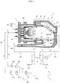
- Fig. 1 is a diagram showing a configuration example of a gas turbine plant applied with a gas turbine combustor (hereinafter, combustor) according to this embodiment.
- a gas turbine plant 1 according to this embodiment includes an air compressor 2, a combustor 3, a turbine 4, and a generator 11.
- the air compressor 2 compresses air 101 sucked via an air intake section (not shown in the figure) to generate high-pressure compressed air (combustion air) 102 and supplies the compressed air 102 to the combustor 3.
- the combustor 3 mixes the combustion air 102 supplied from the air compressor 2 and fuel supplied from a fuel supply system 200 (explained below) and burns that to generate high-temperature combustion gas 110, and supplies the combustion gas 110 to the turbine 4.
- the combustion gas 110 supplied from the combustor 3 expands, whereby the turbine 4 is driven to rotate.
- the combustion gas 110 that has driven the turbine 4 is discharged from the turbine 4 as exhaust gas 113.
- the generator 11 is coaxially coupled to the turbine 4 and converts rotating power of the turbine 4 into power. Note that, in this embodiment, the air compressor 2, the turbine 4, and the generator 11 are coupled to one another by a shaft 15.
- the combustor 3 is attached to a casing 16 of a gas turbine.
- the combustor 3 includes a transition piece 6, an end cover 7, a burner 8, a diffuser 9, an outer casing 10, an inner casing (a combustion liner) 12, a turbine casing 13, a flow sleeve of liner 14, a flow sleeve of transition piece 19, and the fuel supply system 200.
- the inner casing 12 is provided on a downstream side in a flowing direction of the combustion gas 110 of the burner 8. "Upstream” and “downstream” of the flowing direction of the combustion gas 110 are hereinafter referred to as “combustion gas upstream” and “combustion gas downstream”.
- the inner casing 12 is formed in a cylindrical shape and partitions the compressed air 102 supplied from the air compressor 2 and the combustion gas 110 generated by the combustor 3.
- the outer casing 10 and the flow sleeve of liner 14 are provided on the outer circumference side of the inner casing 12.
- the outer casing 10 is formed in a cylindrical shape to cover a combustion gas upstream side on the outer circumference side of the inner casing 12.
- the flow sleeve of liner 14 is provided on a combustion gas downstream side of the outer casing 10.
- the flow sleeve of liner 14 is formed in a cylindrical shape to cover the combustion gas downstream side on the outer circumference side of the inner casing 12.
- An annular space formed between the inner casing 12 and the outer casing 10 and the flow sleeve of liner 14 forms an annular channel (a first annular channel) 17 in which the compressed air 102 supplied from the air compressor 2 to the combustor 3 flows.
- the compressed air 102 supplied from the air compressor 2 to the combustor 3 is guided to the turbine casing 13 through the diffuser 9.
- the diffuser 9 has a function of decelerating the compressed air 102 supplied from the air compressor 2 to the combustor 3 and recovering pressure.
- a part of the compressed air 102 guided to the turbine casing 13 flows into the first annular channel 17 from the turbine casing 13.
- the compressed air 102 flowing in the first annular channel 17 convection-cools the inner casing 12 from the outer circumferential surface side of the inner casing 12.
- a large number of holes (not shown in the figure) are formed on the wall surface of the inner casing 12.
- Apart of the compressed air 102 flowing in the first annular channel 17 flows into the inside of the inner casing 12 from the large number of holes formed on the wall surface of the inner casing 12 as cooling air 103 and is used for film cooling of the inner circumferential surface of the inner casing 12.
- a part not used for the film cooling of the inner casing 12 flows in the first annular channel 17 as air for combustion 104 and reaches the burner 8.
- the air for combustion 104 reached the burner 8 is jetted into a combustion chamber 5 (explained below) together with fuel supplied to the burner 8 from the fuel supply system 200 and is burned.
- the end cover 7 is provided on the downstream side in a flowing direction of the compressed air 102 flowing in the first annular channel 17 of the outer casing 10 (hereinafter, compressed air downstream side). The end cover 7 closes the end portion on the compressed air downstream side of the outer casing 10.
- the combustion chamber 5 is formed on the inside of the inner casing 12.
- an air fuel mixture of the compressed air 102 supplied from the air compressor 2 and the fuel supplied from the fuel supply system 200 is burned and the combustion gas 110 is generated.
- the other end of the transition piece 6 is connected to a duct (not shown in the figure) that connects the combustor 3 and the turbine 4.
- the transition piece 6 has a function of guiding the combustion gas 110 generated in the combustion chamber 5 to the turbine 4.
- the flow sleeve of transition piece 19 is provided on the downstream side of the flow sleeve of liner 14.
- the flow sleeve of transition piece 19 is formed in a cylindrical shape to cover the outer circumference side of the transition piece 6.
- An annular space formed between the transition piece 6 and the flow sleeve of transition piece 19 forms an annular channel (a second annular channel) 18 that guides the compressed air 102 flowed in from the turbine casing 13 to the first annular channel 17. That is, in the compressed air 102 guided to the turbine casing 13, a part flowed into the second annular channel 18 is guided to the first annular channel 17 through the second annular channel 18.
- the compressed air 102 flowing in the second annular channel 18 convection-cools the transition piece 6 from the outer circumferential surface side of the transition piece 6.
- the fuel supply system 200 includes a fuel supply source 210, a common fuel supply system 211, and first and second fuel supply systems 201 and 202.
- the fuel supply source 210 is a supply source of fuel supplied to the first and second fuel supply systems 201 and 202.
- the common fuel supply system 211 is connected to the fuel supply source 210.
- a fuel shut valve (an on-off valve) 60 is provided in the common fuel supply system 211.
- the first and second fuel supply systems 201 and 202 divide in parallel from the common fuel supply system 211 and are connected to a fuel plenum 23 (first and second fuel plenums 23A and 23B) provided on the inside of the end cover 7.
- the number of fuel supply systems dividing from the common fuel supply system 211 is not limited to two.
- a first fuel pressure control valve 61a and a first fuel flow control valve 61b are provided in the first fuel supply system 201.
- a second fuel pressure control valve 62a and a second fuel flow control valve 62b are provided in the second fuel supply system 202.
- the first and second fuel pressure control valves 61a and 62a and the first and second fuel flow control valves 61b and 62b are configured to be individually controllable.
- the fuel supplied from the fuel supply source 210 to the first and second fuel plenums 23A and 23B though the first and second fuel supply systems 201 and 202 is jetted from the tip of a fuel nozzle 22 (explained below) and supplied to the combustion chamber 5.
- a flow rate of the fuel supplied to the first fuel plenum 23A through the first fuel supply system 201 (hereinafter, F1 fuel) is controlled by the first fuel flow control valve 61b.
- a flow rate of the fuel supplied to the second fuel plenum 23B through the second fuel supply system 202 (hereinafter, F2 fuel) is controlled by the second fuel flow control valve 62b.
- the flow rates of the F1 and F2 fuels are individually controlled by the first and second fuel flow control valves 61b and 62b, whereby a power generation amount of the gas turbine plant 1 is controlled.
- the F1 and F2 fuels for example, hydrogen containing fuels such as coke oven gas, oil refinery off-gas, and coal gasification gas and gas fuels such as liquefied natural gas (LNG) can be adopted.
- Fig. 2 is a partial cross-sectional view showing the structure near the burner of the combustor according to this embodiment.
- the burner 8 is divided into a plurality of (in this embodiment, three) annular rows having a concentric circle shape centering on a central axis (not shown in the figure) of the inner casing 12.
- the plurality of annular rows are referred to as first row, second row, and third row as appropriate from the inner circumference side toward the outer circumference side.
- the first row configuring an innermost region among the plurality of annular rows configures a first burner 8A
- the second row configures a second burner 8B
- the third row configures a third burner 8C.
- the F1 fuel is supplied to the first burner 8A via the first fuel plenum 23A.
- the F2 fuel is supplied to the second and third burners 8B and 8C via the second fuel plenum 23B.
- the F1 and F2 fuels supplied to the first to third burners 8A to 8C flow into the fuel nozzles 22 and are jetted to the combustion chamber 5.
- the burner 8 includes a plurality of fuel nozzles 22, an air hole plate 20, and a plate lip 25.
- the plurality of fuel nozzles 22 are supported by the end cover 7.
- the plurality of fuel nozzles 22 are formed in a cylindrical shape and jet the fuel supplied from the fuel supply system 200 (see Fig. 1 ) toward the air hole plate 20.
- the plurality of fuel nozzles 22 are disposed in first to third rows in a concentric circle shape and provided (annularly disposed) at an interval in the circumferential direction in the respective rows.
- the air hole plate 20 is a plate having a disk shape coaxial with the inner casing 12 and is disposed on the downstream side in a flowing direction of the fuel with respect to the plurality of fuel nozzles 22. "Upstream” and “downstream” of the flowing direction of the fuel are hereinafter referred to as “fuel upstream” and “fuel downstream”.
- the plate lip 25 is provided on the outer circumference side of the air hole plate 20.
- Fig. 4 is an enlarged view of a region A surrounded by a dotted line in Fig. 2 .
- the outer circumferential surface of the air hole plate 20 includes a first outer circumferential surface (a first surface) 28 joined to the plate lip 25 and a second outer circumferential surface (a second surface) 29 provided on the fuel downstream side of the first surface 28 and located further on the radial direction inner side of the air hole plate 20 than the first surface 28 to form a space 40 between the second outer circumferential surface and the inner circumferential surface of the plate lip 25. That is, the second surface 29 of the air hole plate 20 is formed to be opposed to the inner circumference surface of the plate lip 25 across the space 40.
- the air hole plate 20 is supported by the plate lip 25 via the first surface 28.
- Fig. 3 is a diagram of the air hole plate according to this embodiment viewed from the combustion gas downstream side.
- a plurality of air holes 21 corresponding to the plurality of fuel nozzles 22 are formed. That is, the plurality of air holes 21 are disposed in a concentric circle shape in first to third rows and provided over the entire circumferences of the air hole rows (disposed annularly). In the plurality of air holes 21, one air hole is disposed on the fuel downstream side of one fuel nozzle 22 to correspond to the fuel nozzle 22. In this embodiment, the tips of the plurality of fuel nozzles 22 are inserted into the plurality of air holes 21. Note that the air hole plate 20 may be disposed separately from the tips of the plurality of fuel nozzles 22 to prevent the tips of the plurality of fuel nozzles 22 from being inserted into the plurality of air holes 21.
- the plurality of air holes 21 are formed in an oblique columnar shape in which two ellipses forming opening sections on the fuel upstream side and downstream side and a bus are not orthogonal.
- the opening section on the fuel upstream side of an air hole 33B is referred to as "inlet” and the opening section on the fuel downstream side is referred to as "outlet”.
- the plurality of air holes 21 are turning air holes having a turning angle.
- the outlet shifts in the circumferential direction of the air hole plate 20 with respect to the inlet. That is, the plurality of air holes 21 are formed such that a center line obtained by connecting the centers of the inlet and the outlet inclines in the circumferential direction with respect to the air hole plate 20.
- the plate lip 25 is formed in a cylindrical shape to cover the outer circumference side of the air hole plate 20.
- the plate lip 25 is held on the inner side of the inner casing 12 via a spring seal 26.
- the spring seal 26 is provided between the outer circumferential surface of the plate lip 25 and the inner circumferential surface of the inner casing 12.
- An annular space formed between the outer circumferential surface of the plate lip 25 and the inner circumferential surface of the inner casing 12 forms an outer channel 27 for supplying a part of the air for combustion 104 to the outer circumferential part on the plate lip 25 side of the combustion chamber 5 as lip cooling air 105.
- a hole section (not shown in the figure), in which the lip cooling air 105 flowing in the outer channel 27 can circulate, is formed.
- the end portion on the fuel upstream side of the plate lip 25 coincides with the end portion on the fuel upstream side of the air hole plate 20 in a flowing direction of the fuel.
- the end portion on the fuel downstream side of the plate lip 25 is provided to extend (project) further to the combustion gas downstream side than the end portion on the fuel downstream side of the air hole plate 20 in the flowing direction of the fuel.
- a communicating hole 41 is formed in the plate lip 25.
- the communicating hole 41 is provided in a position opposed to the second surface 29 of the air hole plate 20 to pierce through the plate lip 25 in the radial direction of the air hole plate 20 and communicates the outer channel 27 and the space 40. Therefore, a part of the lip cooling air 105 flowing in the outer channel 27 is guided to the space 40 as air for circulation flow 106 via the communicating hole 41.
- the air for circulation flow 106 guided to the space 40 flows in the axial direction of the plate lip 25 in the space 40, flows into the combustion chamber 5 from the space 40, and flows in the combustion chamber 5 along the inner circumferential surface of the plate lip 25.
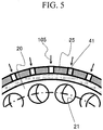
- Fig. 5 is an arrow cross-sectional view taken along line V-V in Fig. 4 .
- a plurality of communicating holes 41 are provided at equal intervals in the circumferential direction of the plate lip 25.
- the compressed air 102 not used for film cooling of the inner casing 12 flows toward the burner 8 in the first annular channel 17. Thereafter, the compressed air 102 is dammed by the end cover 7 to turn and flows into the air holes 21 of the air hole plate 20 as the air for combustion 104.
- the air for combustion 104 flows into the outer channel 27 as the lip cooling air 105 and flows in a direction opposite to a flowing direction of the compressed air 102 flowing in the first annular channel 17.
- the lip cooling air 105 flows through the hole section of the spring seal 26 and is jetted to the outer circumferential part of the combustion chamber 5.
- a part of the lip cooling air 105 flowing in the outer channel 27 is guided to the space 40 as the air for circulation flow 106 via the communicating holes 41 formed in the plate lip 25 and flows into the combustion chamber 5 along the inner circumferential surface of the plate lip 25.
- the fuel supplied to the fuel nozzles 22 from the fuel supply system 200 (see Fig. 1 ) via the fuel plenum 23 is jetted into the air hole 21 of the air hole plate 20 from a jetting port of the tip of the fuel nozzle 22.
- the air hole 21 is formed in the oblique columnar shape in which the two ellipses forming the inlet and the outlet and the bus are not orthogonal. Therefore, a force component in the turning direction is given to the fuel jetted into the air hole 21 while the fuel is mixed with the air for combustion 104.
- An air fuel mixture of the fuel and the air for combustion 104 spouted from the outlet of the air hole 21 is burned while forming the circular vortex 80 in the combustion chamber 5.
- the flame 83 is formed in the combustion chamber 5.
- Fig. 7 is a partial cross-sectional view showing the structure near a burner of a combustor according to this embodiment.
- Fig. 8 is a view of an air hole plate according to this embodiment viewed from a combustion gas downstream side.
- portions equivalent to the portions in the first embodiment are denoted by the same reference numerals and signs and explanation of the components is omitted as appropriate.
- the combustor according to this embodiment is a so-called multi-jetting type gas turbine combustor includes a plurality of burners configured by disposing a plurality of fuel nozzles and a plurality of air holes.
- the combustor is different from the combustor 3 according to the first embodiment in that the combustor includes a fuel supply system 250 and a startup fuel supply system 260 instead of the fuel supply system 200 and further includes a startup nozzle 24.
- the other components are the same as the components of the combustor 3 according to the first embodiment.
- the configuration of a gas turbine plant including the combustor according to this embodiment is the same as the configuration of the gas turbine plant 1 according to the first embodiment.
- the combustor includes one burner (a central burner) 32 disposed coaxially with the inner casing 12 on the upstream side of the combustion chamber 5 and six burners (outer burners) 33 disposed around the central burner 32.
- the central burner 32 is used during the start of a gas turbine or used to secure combustion stability of the entire combustor during a load operation.
- the central burner 32 is divided into two annular rows having a concentric circle shape in this embodiment.
- the annular rows are referred to as first row and second row as appropriate from the inner circumference side toward the outer circumference side.
- the central burner 32 includes the startup nozzle 24, the plurality of fuel nozzles 22 disposed in the first and second rows, and a central air hole group 42 including the plurality of air holes 21 disposed in the first and second rows.
- the startup nozzle (a central fuel nozzle) 24 supplies startup fuel to the combustion chamber 5.
- the startup nozzle 24 is supported coaxially with the inner casing 12 by the end cover 7. That is, the startup nozzle 24 is provided such that the tip portions thereof is located in the center of the air hole plate 20.
- the central air hole group 42 is formed in the center of the air hole plate 20.
- the outer burner 33 is divided into three annular rows having a concentric circle shape in this embodiment.
- the annular rows are referred to as first row, second row, and third row as appropriate from the inner circumference side toward the outer circumference side.
- the outer burner 33 includes the plurality of fuel nozzles 22 disposed in the first to third rows and an outer air hole group 44 including the plurality of air holes 21 disposed in the first to third rows.
- the outer air hole group 44 is formed on the outer circumference side of the central air hole group 42 of the air hole plate 20 to surround the central air hole group 42.
- the central burner 32 and the outer burner 33 share the air hole plate 20.
- the fuel supply system 250 includes the fuel supply source 210, the common fuel supply system 211, and third to fifth fuel supply systems 203 to 205.
- the third to fifth fuel supply systems 203 to 205 divide from the common fuel supply system 211 in parallel.
- the third to fifth fuel supply systems 203 to 205 are connected to a fuel plenum 43 (third to fifth fuel plenums 43A to 43C) provided on the inside of the end cover 7.
- a third fuel pressure control valve 73a and a third fuel flow control valve 73b are provided in the third fuel supply system 203.
- a fourth fuel pressure control valve 74a and a fourth fuel flow control valve 74b are provided in the fourth fuel supply system 204.
- a fifth fuel pressure control valve 75a and a fifth fuel flow control valve 75b are provided in the fifth fuel supply system 205.
- the third to fifth fuel pressure control valves 73a to 75a and the third to fifth fuel flow control valves 73b to 75b are configured to be individually controllable.
- the fuel supplied from the fuel supply source 210 to the third to fifth fuel plenums 43A to 43C through the third to fifth fuel supply systems 203 to 205 is jetted from the tips of the fuel nozzles 22 and supplied to the combustion chamber 5.
- a flow rate of the fuel supplied to the third fuel plenum 43A through the third fuel supply system 203 (hereinafter, F3 fuel) is controlled by the third fuel flow control valve 73b.
- the fuel supplied to fourth and fifth fuel plenums 43B and 43C through the fourth and fifth fuel supply systems 204 and 205 (hereinafter, F4 and F5 fuels) is controlled by the fourth and fifth fuel flow control valves 74b and 75b.
- the startup fuel supply system 260 includes a startup fuel supply source 270 and a startup system 206.
- the startup fuel supply source 270 is a supply source of startup fuel supplied to the startup system 206.
- the startup system 206 connects the startup fuel supply source 270 and the startup nozzle 24.
- a startup fuel pressure control valve 76a and a startup fuel flow control valve 76b are provided in the startup system 206.
- the startup fuel supplied from the startup fuel supply source 270 to the startup nozzle 24 through the startup system 206 is jetted from the tip of the startup nozzle 24 and supplied to the combustion chamber 5.
- a flow rate of the startup fuel supplied to the startup nozzle 24 through the startup system 206 is controlled by the startup fuel flow control valve 76b.
- the startup fuel liquid fuel such as diesel oil and heavy oil can be adopted.
- the plurality of (in Fig. 8 , five) communicating holes 41 are provided in each of positions corresponding to the outer air hole groups 44 in the circumferential direction of the plate lip 25. That is, the communicating holes 41 are provided in the same phase as the outer air hole groups 44 in the circumferential direction of the plate lip 25 and are not provided in a position corresponding to a space between two outer burners 33 adjacent to each other.
- the air hole 21 is formed with the central axis, which is obtained by connecting the centers of the inlet and the outlet, inclining in the circumferential direction with respect to the air hole plate 20. Therefore, combustion gas (outer burner combustion gas) 112 formed by the fuel jetted from a part (the air holes 21 disposed in positions opposed to the inner circumferential surface of the plate lip 25) of the air holes 21 disposed in the outermost circumference of the outer air hole group 44 is likely to come into contact with the inner circumferential surface of the plate lip 25 and heat the inner circumferential surface of the plate lip 25 (see Fig. 8 ).
- the plurality of communicating holes 41 are provided in each of the positions corresponding to the outer air hole groups 44. Therefore, the outer burner combustion gas 112 can be washed away to the combustion gas downstream side by the air for circulation flow 106 flowing into the space 40 from the communicating holes 41 and flowing in the combustion chamber 5 along the inner circumferential surface of the plate lip 25. Therefore, it is possible to suppress heating of the inner circumferential surface of the plate lip 25 by the outer burner combustion gas 112.
- the air for circulation flow 106 mixes with the outer burner combustion gas 112, whereby the temperature of the outer burner combustion gas 112 can be reduced. Therefore, it is possible to locally reduce the temperature of the combustion gas 110 and suppress NOx emissions.
- Fig. 9 is a view of an air hole plate according to this embodiment viewed from a combustion gas downstream side.
- portions equivalent to the portions in the second embodiment are denoted by the same reference numerals and signs and explanation of the portions is omitted as appropriate.
- a combustor according to this embodiment is different from the combustor in the second embodiment in positions where the communicating holes 41 are provided.
- the other components are the same as the components of the combustor according to the second embodiment.
- the plurality of (in Fig. 9 , five) communicating holes 41 are provided in each of positions corresponding to a space between two outer air hole groups 44 adjacent to each other in the circumferential direction of the plate lip 25.
- combustion gas (central burner combustion gas) 111 formed by startup fuel jetted from the startup nozzle 24 and fuel jetted from the air holes 21 of the central burner 32 passes a region between two outer burners 33 adjacent to each other and spreads to the outer circumferential part of the combustion chamber 5, it is likely that a portion corresponding to the region between the two outer burners 33 adjacent to each other on the inner circumferential surface of the plate lip 25 is heated by the central burner combustion gas 111.
- the plurality of communicating holes 41 are provided in the position corresponding to the space between the two outer air hole groups 44 adjacent to each other. Therefore, the central burner combustion gas 111 can be washed away to the combustion gas downstream side by the air for circulation flow 106 flowing into the space 40 from the communicating holes 41 and flowing in the combustion chamber 5 along the inner circumferential surface of the plate lip 25. Therefore, it is possible to suppress the heating of the inner circumferential surface of the plate lip 25 by the central burner combustion gas 111. Since the central burner combustion gas 111 is washed away to the combustion gas downstream side by the air for circulation flow 106, it is possible to suppress the adhesion of the un-evaporated fuel to the inner circumferential surface of the plate lip 25.
- a turning direction of an air fuel mixture spouted from the air holes 21 of the central burner 32 and a turning direction of an air fuel mixture spouted from the air holes 21 of the outer burner 33 are opposite directions.
- the same action and effects can be obtained even when the turning directions are the same direction.
- the present invention is not limited to the embodiments explained above and includes various modifications.
- the embodiments are explained in detail in order to clearly explain the present invention and are not always limited to the embodiments including all the components explained above.
- a part of the components of a certain embodiment can be replaced with the components of the other embodiment.
- the components of the other embodiments can be added to the components of a certain embodiment.
- the configuration is illustrated in which a part of the outer circumferential surface of the air hole plate 20 is formed in the position further on the radial direction inner side of the air hole plate 20 than the joined surface of the air hole plate 20 and the plate lip 25, and the space 40 is formed between the air hole plate 20 and the plate lip 25.
- the essential effect of the present invention is to reduce thermal stress that occurs in the burner and secure reliability of the gas turbine combustor.
- the present invention is not always limited to the configuration as long as the essential effect is obtained.
- a part of the inner circumferential surface of the plate lip 25 may be formed in a position further on the radial direction outer side of the plate lip 25 than the joined surface of the air hole plate 20 and the plate lip 25, and the space 40 may be formed between the air hole plate 20 and the plate lip 25.
- the configuration is illustrated in which the plurality of communicating holes 41 are provided at equal intervals in the circumferential direction of the plate lip 25.
- the present invention is not always limited to the configuration as long as the essential effect of the present invention is obtained.
- the communicating holes 41 may be provided at varied intervals in the circumferential direction of the plate lip 25.
- the configuration is illustrated in which the air holes 21 of the air hole plate 20 are formed over the entire circumferences of the annular rows.
- the present invention is not always limited to the configuration as long as the essential effect of the present invention is obtained.
- the air holes 21 may be formed in parts of the annular rows.
Landscapes
- Engineering & Computer Science (AREA)
- Chemical & Material Sciences (AREA)
- Combustion & Propulsion (AREA)
- Mechanical Engineering (AREA)
- General Engineering & Computer Science (AREA)
Abstract
Description
- The present invention relates to a gas turbine combustor.
- In a gas turbine power generation plant, in order to reduce emissions of carbon dioxide (CO2) that causes global warming, it has been examined to improve power generation efficiency and use fuel containing hydrogen (hereinafter, hydrogen-containing fuel) as fuel of a gas turbine combustor instead of fossil fuel.
- In general, in order to improve power generation efficiency, it is effective to increase an inlet temperature of a turbine (hereinafter, turbine inlet temperature). However, when the turbine inlet temperature is increased, emissions of nitrogen oxide (NOx), which is environmental pollutants, increase. Therefore, it is necessary to reduce the NOx emissions while increasing the turbine inlet temperature.
- As a method of reducing the NOx emissions, there is a method of coaxially disposing a fuel jet and a combustion air channel and supplying a jet to a combustion chamber as a coaxial jet with a fuel flow embraced by an air flow (see
JP-A-2003-148734 - In
JP-A-2003-148734 - However, in general, since the outer circumferential part of the burner wall surface is bound by a fixing member, when the burner wall surface expands according to the temperature rise, thermal stress occurs in a joined section of the burner wall surface and the fixing member. The thermal stress could occur every time the gas turbine is started. Therefore, cyclic stress is applied to the joined section, and reliability of the gas turbine combustor could be deteriorated.
- The present invention has been devised in view of the above and an object of the present invention is to reduce thermal stress that occurs in a burner and secure reliability of a gas turbine combustor.
- In order to achieve the object, a gas turbine combustor according to the present invention includes: an inner casing that forms a combustion chamber on an inside; an outer casing that covers an outer circumference side of the inner casing; an annular channel formed between the inner casing and the outer casing, compressed air flowing in the annular channel; an end-cover provided on a downstream side in a flowing direction of the compressed air of the outer casing; a plurality of fuel nozzles supported by the end cover, the plurality of fuel nozzles jetting fuel; an air hole plate including a plurality of air holes formed to correspond to the plurality of fuel nozzles, the air hole plate being provided on the downstream side in a flowing direction of the fuel of the plurality of fuel nozzles; a plate lip that covers an outer circumference side of the air hole plate; and/or an outer channel formed between an outer circumferential surface of the plate lip and the inner casing, the outer channel supplying the compressed air to an outer circumferential part of a portion on the plate lip side of the combustion chamber. An outer circumferential surface of the air hole plate includes a first surface joined to the plate lip and a second surface provided on the downstream side in the flowing direction of the fuel of the first surface and located further on a radial direction inner side of the air hole plate than the first surface to form a space between the second surface and an inner circumferential surface of the plate lip. A communicating hole that connects the outer channel and the space is provided in the plate lip.
- According to the present invention, it is possible to reduce thermal stress that occurs in a burner and secure reliability of the gas turbine combustor.
-
-
Fig. 1 is a diagram showing a configuration example of a gas turbine plant applied with a combustor according to a first embodiment of the present invention; -
Fig. 2 is a partial cross-sectional view showing the structure near a burner of the combustor according to the first embodiment of the present invention; -
Fig. 3 is a view of an air hole plate according to the first embodiment of the present invention viewed from a combustion gas downstream side; -
Fig. 4 is an enlarged view of a region A surrounded by a dotted line inFig. 2 ; -
Fig. 5 is an arrow cross-sectional view taken along line V-V inFig. 4 ; -
Fig. 6 is a partial cross-sectional view showing the structure near a burner of a combustor according to a comparative example; -
Fig. 7 is a partial cross-sectional view showing the structure near a burner of a combustor according to a second embodiment of the present invention; -
Fig. 8 is a view of an air hole plate according to the second embodiment of the present invention viewed from a combustion gas downstream side; and -
Fig. 9 is a view of an air hole plate according to a third embodiment of the present invention viewed from a combustion gas downstream side. -
Fig. 1 is a diagram showing a configuration example of a gas turbine plant applied with a gas turbine combustor (hereinafter, combustor) according to this embodiment. As shown inFig. 1 , agas turbine plant 1 according to this embodiment includes anair compressor 2, acombustor 3, a turbine 4, and agenerator 11. - The
air compressor 2compresses air 101 sucked via an air intake section (not shown in the figure) to generate high-pressure compressed air (combustion air) 102 and supplies thecompressed air 102 to thecombustor 3. Thecombustor 3 mixes thecombustion air 102 supplied from theair compressor 2 and fuel supplied from a fuel supply system 200 (explained below) and burns that to generate high-temperature combustion gas 110, and supplies thecombustion gas 110 to the turbine 4. Thecombustion gas 110 supplied from thecombustor 3 expands, whereby the turbine 4 is driven to rotate. Thecombustion gas 110 that has driven the turbine 4 is discharged from the turbine 4 asexhaust gas 113. Thegenerator 11 is coaxially coupled to the turbine 4 and converts rotating power of the turbine 4 into power. Note that, in this embodiment, theair compressor 2, the turbine 4, and thegenerator 11 are coupled to one another by ashaft 15. - The
combustor 3 is attached to acasing 16 of a gas turbine. Thecombustor 3 includes a transition piece 6, anend cover 7, aburner 8, adiffuser 9, anouter casing 10, an inner casing (a combustion liner) 12, aturbine casing 13, a flow sleeve ofliner 14, a flow sleeve oftransition piece 19, and thefuel supply system 200. - The
inner casing 12 is provided on a downstream side in a flowing direction of thecombustion gas 110 of theburner 8. "Upstream" and "downstream" of the flowing direction of thecombustion gas 110 are hereinafter referred to as "combustion gas upstream" and "combustion gas downstream". Theinner casing 12 is formed in a cylindrical shape and partitions thecompressed air 102 supplied from theair compressor 2 and thecombustion gas 110 generated by thecombustor 3. Theouter casing 10 and the flow sleeve ofliner 14 are provided on the outer circumference side of theinner casing 12. Theouter casing 10 is formed in a cylindrical shape to cover a combustion gas upstream side on the outer circumference side of theinner casing 12. The flow sleeve ofliner 14 is provided on a combustion gas downstream side of theouter casing 10. The flow sleeve ofliner 14 is formed in a cylindrical shape to cover the combustion gas downstream side on the outer circumference side of theinner casing 12. An annular space formed between theinner casing 12 and theouter casing 10 and the flow sleeve ofliner 14 forms an annular channel (a first annular channel) 17 in which thecompressed air 102 supplied from theair compressor 2 to thecombustor 3 flows. In this embodiment, thecompressed air 102 supplied from theair compressor 2 to thecombustor 3 is guided to theturbine casing 13 through thediffuser 9. Thediffuser 9 has a function of decelerating thecompressed air 102 supplied from theair compressor 2 to thecombustor 3 and recovering pressure. A part of thecompressed air 102 guided to theturbine casing 13 flows into the firstannular channel 17 from theturbine casing 13. Thecompressed air 102 flowing in the firstannular channel 17 convection-cools theinner casing 12 from the outer circumferential surface side of theinner casing 12. A large number of holes (not shown in the figure) are formed on the wall surface of theinner casing 12. Apart of thecompressed air 102 flowing in the firstannular channel 17 flows into the inside of theinner casing 12 from the large number of holes formed on the wall surface of theinner casing 12 ascooling air 103 and is used for film cooling of the inner circumferential surface of theinner casing 12. In thecompressed air 102 flowing in the firstannular channel 17, a part not used for the film cooling of theinner casing 12 flows in the firstannular channel 17 as air forcombustion 104 and reaches theburner 8. The air forcombustion 104 reached theburner 8 is jetted into a combustion chamber 5 (explained below) together with fuel supplied to theburner 8 from thefuel supply system 200 and is burned. Theend cover 7 is provided on the downstream side in a flowing direction of thecompressed air 102 flowing in the firstannular channel 17 of the outer casing 10 (hereinafter, compressed air downstream side). Theend cover 7 closes the end portion on the compressed air downstream side of theouter casing 10. - The
combustion chamber 5 is formed on the inside of theinner casing 12. In thecombustion chamber 5, an air fuel mixture of thecompressed air 102 supplied from theair compressor 2 and the fuel supplied from thefuel supply system 200 is burned and thecombustion gas 110 is generated. On a far side from the burner 8 (the combustion gas downstream side) of theinner casing 12, one end of the transition piece 6 is inserted. The other end of the transition piece 6 is connected to a duct (not shown in the figure) that connects thecombustor 3 and the turbine 4. The transition piece 6 has a function of guiding thecombustion gas 110 generated in thecombustion chamber 5 to the turbine 4. The flow sleeve oftransition piece 19 is provided on the downstream side of the flow sleeve ofliner 14. The flow sleeve oftransition piece 19 is formed in a cylindrical shape to cover the outer circumference side of the transition piece 6. An annular space formed between the transition piece 6 and the flow sleeve oftransition piece 19 forms an annular channel (a second annular channel) 18 that guides thecompressed air 102 flowed in from theturbine casing 13 to the firstannular channel 17. That is, in thecompressed air 102 guided to theturbine casing 13, a part flowed into the secondannular channel 18 is guided to the firstannular channel 17 through the secondannular channel 18. Thecompressed air 102 flowing in the secondannular channel 18 convection-cools the transition piece 6 from the outer circumferential surface side of the transition piece 6. - The
fuel supply system 200 includes afuel supply source 210, a commonfuel supply system 211, and first and secondfuel supply systems fuel supply source 210 is a supply source of fuel supplied to the first and secondfuel supply systems fuel supply system 211 is connected to thefuel supply source 210. A fuel shut valve (an on-off valve) 60 is provided in the commonfuel supply system 211. The first and secondfuel supply systems fuel supply system 211 and are connected to a fuel plenum 23 (first andsecond fuel plenums end cover 7. By providing a plurality of (in this embodiment, two) fuel supply systems in this way, it is possible to improve a degree of freedom of operation of thegas turbine plant 1. Note that the number of fuel supply systems dividing from the commonfuel supply system 211 is not limited to two. In the firstfuel supply system 201, a first fuelpressure control valve 61a and a first fuelflow control valve 61b are provided. In the secondfuel supply system 202, a second fuelpressure control valve 62a and a second fuelflow control valve 62b are provided. The first and second fuelpressure control valves flow control valves - The fuel supplied from the
fuel supply source 210 to the first andsecond fuel plenums fuel supply systems combustion chamber 5. A flow rate of the fuel supplied to thefirst fuel plenum 23A through the first fuel supply system 201 (hereinafter, F1 fuel) is controlled by the first fuelflow control valve 61b. Similarly, a flow rate of the fuel supplied to thesecond fuel plenum 23B through the second fuel supply system 202 (hereinafter, F2 fuel) is controlled by the second fuelflow control valve 62b. In this embodiment, the flow rates of the F1 and F2 fuels are individually controlled by the first and second fuelflow control valves gas turbine plant 1 is controlled. Note that, as the F1 and F2 fuels, for example, hydrogen containing fuels such as coke oven gas, oil refinery off-gas, and coal gasification gas and gas fuels such as liquefied natural gas (LNG) can be adopted. -
Fig. 2 is a partial cross-sectional view showing the structure near the burner of the combustor according to this embodiment. - As shown in
Fig. 2 , theburner 8 is divided into a plurality of (in this embodiment, three) annular rows having a concentric circle shape centering on a central axis (not shown in the figure) of theinner casing 12. The plurality of annular rows are referred to as first row, second row, and third row as appropriate from the inner circumference side toward the outer circumference side. - In this embodiment, the first row configuring an innermost region among the plurality of annular rows configures a
first burner 8A, the second row configures asecond burner 8B, and the third row configures athird burner 8C. The F1 fuel is supplied to thefirst burner 8A via thefirst fuel plenum 23A. The F2 fuel is supplied to the second andthird burners second fuel plenum 23B. The F1 and F2 fuels supplied to the first tothird burners 8A to 8C flow into thefuel nozzles 22 and are jetted to thecombustion chamber 5. Theburner 8 includes a plurality offuel nozzles 22, anair hole plate 20, and aplate lip 25. - The plurality of
fuel nozzles 22 are supported by theend cover 7. The plurality offuel nozzles 22 are formed in a cylindrical shape and jet the fuel supplied from the fuel supply system 200 (seeFig. 1 ) toward theair hole plate 20. The plurality offuel nozzles 22 are disposed in first to third rows in a concentric circle shape and provided (annularly disposed) at an interval in the circumferential direction in the respective rows. - The
air hole plate 20 is a plate having a disk shape coaxial with theinner casing 12 and is disposed on the downstream side in a flowing direction of the fuel with respect to the plurality offuel nozzles 22. "Upstream" and "downstream" of the flowing direction of the fuel are hereinafter referred to as "fuel upstream" and "fuel downstream". Theplate lip 25 is provided on the outer circumference side of theair hole plate 20. -
Fig. 4 is an enlarged view of a region A surrounded by a dotted line inFig. 2 . As shown inFig. 4 , the outer circumferential surface of theair hole plate 20 includes a first outer circumferential surface (a first surface) 28 joined to theplate lip 25 and a second outer circumferential surface (a second surface) 29 provided on the fuel downstream side of thefirst surface 28 and located further on the radial direction inner side of theair hole plate 20 than thefirst surface 28 to form aspace 40 between the second outer circumferential surface and the inner circumferential surface of theplate lip 25. That is, thesecond surface 29 of theair hole plate 20 is formed to be opposed to the inner circumference surface of theplate lip 25 across thespace 40. Theair hole plate 20 is supported by theplate lip 25 via thefirst surface 28. -
Fig. 3 is a diagram of the air hole plate according to this embodiment viewed from the combustion gas downstream side. - As shown in
Fig. 3 , in theair hole plate 20, a plurality ofair holes 21 corresponding to the plurality offuel nozzles 22 are formed. That is, the plurality ofair holes 21 are disposed in a concentric circle shape in first to third rows and provided over the entire circumferences of the air hole rows (disposed annularly). In the plurality ofair holes 21, one air hole is disposed on the fuel downstream side of onefuel nozzle 22 to correspond to thefuel nozzle 22. In this embodiment, the tips of the plurality offuel nozzles 22 are inserted into the plurality of air holes 21. Note that theair hole plate 20 may be disposed separately from the tips of the plurality offuel nozzles 22 to prevent the tips of the plurality offuel nozzles 22 from being inserted into the plurality of air holes 21. - The plurality of
air holes 21 are formed in an oblique columnar shape in which two ellipses forming opening sections on the fuel upstream side and downstream side and a bus are not orthogonal. In the following explanation, the opening section on the fuel upstream side of an air hole 33B is referred to as "inlet" and the opening section on the fuel downstream side is referred to as "outlet". The plurality ofair holes 21 are turning air holes having a turning angle. The outlet shifts in the circumferential direction of theair hole plate 20 with respect to the inlet. That is, the plurality ofair holes 21 are formed such that a center line obtained by connecting the centers of the inlet and the outlet inclines in the circumferential direction with respect to theair hole plate 20. Therefore, a turning component is given to the air forcombustion 104 flowed into the plurality of air holes 21. Since theair hole plate 20 is disposed coaxially with theinner casing 12 as explained above, the air forcombustion 104 jetted to thecombustion chamber 5 from the plurality ofair holes 21 turns around the central axis of theinner casing 12. Consequently, acircular vortex 80 is formed in thecombustion chamber 5 and aflame 83 is stabilized. - As shown in
Fig. 2 , theplate lip 25 is formed in a cylindrical shape to cover the outer circumference side of theair hole plate 20. Theplate lip 25 is held on the inner side of theinner casing 12 via aspring seal 26. Thespring seal 26 is provided between the outer circumferential surface of theplate lip 25 and the inner circumferential surface of theinner casing 12. An annular space formed between the outer circumferential surface of theplate lip 25 and the inner circumferential surface of theinner casing 12 forms anouter channel 27 for supplying a part of the air forcombustion 104 to the outer circumferential part on theplate lip 25 side of thecombustion chamber 5 aslip cooling air 105. In thespring seal 26, a hole section (not shown in the figure), in which thelip cooling air 105 flowing in theouter channel 27 can circulate, is formed. The end portion on the fuel upstream side of theplate lip 25 coincides with the end portion on the fuel upstream side of theair hole plate 20 in a flowing direction of the fuel. On the other hand, the end portion on the fuel downstream side of theplate lip 25 is provided to extend (project) further to the combustion gas downstream side than the end portion on the fuel downstream side of theair hole plate 20 in the flowing direction of the fuel. By securing large thickness in the flowing direction of the fuel of theplate lip 25 with respect to theair hole plate 20, theair hole plate 20 is surely held on theinner casing 12 by thespring seal 26 via theplate lip 25. Note that, in this embodiment, theplate lip 25 is formed of a material same as the material of theair hole plate 20. - As shown in
Fig. 4 , a communicatinghole 41 is formed in theplate lip 25. The communicatinghole 41 is provided in a position opposed to thesecond surface 29 of theair hole plate 20 to pierce through theplate lip 25 in the radial direction of theair hole plate 20 and communicates theouter channel 27 and thespace 40. Therefore, a part of thelip cooling air 105 flowing in theouter channel 27 is guided to thespace 40 as air forcirculation flow 106 via the communicatinghole 41. The air forcirculation flow 106 guided to thespace 40 flows in the axial direction of theplate lip 25 in thespace 40, flows into thecombustion chamber 5 from thespace 40, and flows in thecombustion chamber 5 along the inner circumferential surface of theplate lip 25. -
Fig. 5 is an arrow cross-sectional view taken along line V-V inFig. 4 . As shown inFig. 5 , in this embodiment, a plurality of communicatingholes 41 are provided at equal intervals in the circumferential direction of theplate lip 25. - Flows of the fuel and the air around the
burner 8 according to this embodiment are explained with reference toFig. 2 . - As shown in
Fig. 2 , thecompressed air 102 not used for film cooling of theinner casing 12 flows toward theburner 8 in the firstannular channel 17. Thereafter, thecompressed air 102 is dammed by theend cover 7 to turn and flows into the air holes 21 of theair hole plate 20 as the air forcombustion 104. Apart of the air forcombustion 104 flows into theouter channel 27 as thelip cooling air 105 and flows in a direction opposite to a flowing direction of thecompressed air 102 flowing in the firstannular channel 17. Thelip cooling air 105 flows through the hole section of thespring seal 26 and is jetted to the outer circumferential part of thecombustion chamber 5. A part of thelip cooling air 105 flowing in theouter channel 27 is guided to thespace 40 as the air forcirculation flow 106 via the communicatingholes 41 formed in theplate lip 25 and flows into thecombustion chamber 5 along the inner circumferential surface of theplate lip 25. - On the other hand, the fuel supplied to the
fuel nozzles 22 from the fuel supply system 200 (seeFig. 1 ) via thefuel plenum 23 is jetted into theair hole 21 of theair hole plate 20 from a jetting port of the tip of thefuel nozzle 22. As explained above, theair hole 21 is formed in the oblique columnar shape in which the two ellipses forming the inlet and the outlet and the bus are not orthogonal. Therefore, a force component in the turning direction is given to the fuel jetted into theair hole 21 while the fuel is mixed with the air forcombustion 104. An air fuel mixture of the fuel and the air forcombustion 104 spouted from the outlet of theair hole 21 is burned while forming thecircular vortex 80 in thecombustion chamber 5. Theflame 83 is formed in thecombustion chamber 5. -
- (1)
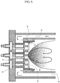
Fig. 6 is a partial cross-sectional view showing the structure near a burner of a combustor according to a comparative example.
In the burner of the combustor shown inFig. 6 , the entire outer circumferential surface of an air hole plate P is joined to a plate lip L. A space is absent between the air hole plate P and the plate lip L. An element corresponding to the communicatinghole 41 in this embodiment is absent.
In the burner of the combustor according to the comparative example, the temperature of a wall surface facing a combustion chamber C side (a combustion chamber side wall surface) of the air hole plate P rises with heat from a flame F formed near an outlet of an air hole H of the air hole plate P. Thermal expansion E to the radial direction outer side occurs in the air hole plate P (i.e., the air hole plate P expands to the radial direction outer side). However, as explained above, the outer circumferential part of the air hole plate P is bound by the plate lip L. Therefore, thermal stress S occurs in a joined part of the combustion chamber side wall surface of the air hole plate P and the plate lip L. In particular, when hydrogen-contained fuel is used as fuel supplied to the combustor, since hydrogen has low minimum ignition energy (minimum energy necessary for ignition) and is easily ignited, has a wide flammable range, and has high flame speed, it is likely that the flame F further approaches the combustion chamber side wall surface of the air hole plate P. In this case, since radiation heat from the flame F increases, the temperature of the air hole plate P further rises and the thermal stress S that occurs in the joined part increases. As explained above, reliability of the combustor could be deteriorated when the thermal stress S occurs in the joined part of the air hole plate P and the plate lip L.
In the burner of the combustor according to the comparative example, a region near the combustion chamber side wall surface of the air hole plate P near the plate lip L is a stagnation region. Therefore, a recirculation flow region X could occur in this region. In this case, a part of high-temperature combustion gas generated near an outlet of an air hole disposed in the outermost circumference of the air hole plate P is returned to the region by the recirculation flow region X. Consequently, the temperature of the combustion chamber side wall surface on the radial direction outer side of the air hole plate P further rises and the thermal stress S increases.
On the other hand, as shown inFig. 4 , in this embodiment, thespace 40 is formed between theair hole plate 20 and theplate lip 25. Therefore, it is possible to absorb, in thespace 40, thethermal expansion 90 that occurs in theair hole plate 20 and move a position where thethermal stress 91 occurs from the joined part to a bottom portion of the space 40 (a connected part of awall surface 30, which connects thefirst surface 28 and thesecond surface 29, and the second surface 29). The bottomportion of thespace 40 is more distant from thecombustion chamber 5 than the combustion chamber side wall surface of theair hole plate 20. A heat transfer amount from combustion gas decreases. Cooling action by the air forcombustion 104 from theend cover 7 side increases. Therefore, metal temperature is lower than the temperature of the combustion chamber side wall surface of theair hole plate 20.
In addition, in this embodiment, the communicatinghole 41 that communicates theouter channel 27 and thespace 40 is provided in theplate lip 25. Therefore, it is possible to guide a part of thelip cooling air 105 flowing in theouter channel 27 to thespace 40 as the air ofcirculation flow 106, jet the part of thelip cooling air 105 to thecombustion chamber 5 along the inner circumferential surface of theplate lip 25, and wash away the recirculation flow region X explained in the comparative example to the combustion gas downstream side. Consequently, it is possible to suppress a temperature rise of theair hole plate 20 due to a backflow of a part of the combustion gas. By jetting the air forcirculation flow 106 to thecombustion chamber 5 along the inner circumferential surface of theplate lip 25, it is possible to cool the inner circumferential surface of theplate lip 25 and, at the same time, suppress approach of theflame 83 to theplate lip 25. Further, by guiding the air forcirculation flow 106 to thespace 40, it is possible to cool the bottom portion of thespace 40 and theair hole plate 20.
Consequently, it is possible to reduce thethermal stress 91 that occurs in the bottom portion of thespace 40 of theair hole plate 20 and secure reliability of thecombustor 3. - (2) In this embodiment, the plurality of communicating
holes 41 are provided at equal intervals in the circumferential direction of theplate lip 25. Therefore, it is possible to reduce ununiformity of jetting positions of the air forcirculation flow 106 to thecombustion chamber 5 and uniformly suppress a temperature rise of theair hole plate 20. -
Fig. 7 is a partial cross-sectional view showing the structure near a burner of a combustor according to this embodiment.Fig. 8 is a view of an air hole plate according to this embodiment viewed from a combustion gas downstream side. InFigs. 7 and8 , portions equivalent to the portions in the first embodiment are denoted by the same reference numerals and signs and explanation of the components is omitted as appropriate. - The combustor according to this embodiment is a so-called multi-jetting type gas turbine combustor includes a plurality of burners configured by disposing a plurality of fuel nozzles and a plurality of air holes. The combustor is different from the
combustor 3 according to the first embodiment in that the combustor includes afuel supply system 250 and a startupfuel supply system 260 instead of thefuel supply system 200 and further includes astartup nozzle 24. The other components are the same as the components of thecombustor 3 according to the first embodiment. The configuration of a gas turbine plant including the combustor according to this embodiment is the same as the configuration of thegas turbine plant 1 according to the first embodiment. - As shown in
Figs. 7 and8 , the combustor according to this embodiment includes one burner (a central burner) 32 disposed coaxially with theinner casing 12 on the upstream side of thecombustion chamber 5 and six burners (outer burners) 33 disposed around thecentral burner 32. - For example, the
central burner 32 is used during the start of a gas turbine or used to secure combustion stability of the entire combustor during a load operation. Thecentral burner 32 is divided into two annular rows having a concentric circle shape in this embodiment. The annular rows are referred to as first row and second row as appropriate from the inner circumference side toward the outer circumference side. Thecentral burner 32 includes thestartup nozzle 24, the plurality offuel nozzles 22 disposed in the first and second rows, and a centralair hole group 42 including the plurality ofair holes 21 disposed in the first and second rows. - The startup nozzle (a central fuel nozzle) 24 supplies startup fuel to the
combustion chamber 5. Thestartup nozzle 24 is supported coaxially with theinner casing 12 by theend cover 7. That is, thestartup nozzle 24 is provided such that the tip portions thereof is located in the center of theair hole plate 20. The centralair hole group 42 is formed in the center of theair hole plate 20. - The
outer burner 33 is divided into three annular rows having a concentric circle shape in this embodiment. The annular rows are referred to as first row, second row, and third row as appropriate from the inner circumference side toward the outer circumference side. Theouter burner 33 includes the plurality offuel nozzles 22 disposed in the first to third rows and an outerair hole group 44 including the plurality ofair holes 21 disposed in the first to third rows. - The outer
air hole group 44 is formed on the outer circumference side of the centralair hole group 42 of theair hole plate 20 to surround the centralair hole group 42. In this embodiment, thecentral burner 32 and theouter burner 33 share theair hole plate 20. - As shown in
Fig. 7 , thefuel supply system 250 includes thefuel supply source 210, the commonfuel supply system 211, and third to fifthfuel supply systems 203 to 205. The third to fifthfuel supply systems 203 to 205 divide from the commonfuel supply system 211 in parallel. The third to fifthfuel supply systems 203 to 205 are connected to a fuel plenum 43 (third tofifth fuel plenums 43A to 43C) provided on the inside of theend cover 7. A third fuelpressure control valve 73a and a third fuelflow control valve 73b are provided in the thirdfuel supply system 203. A fourth fuelpressure control valve 74a and a fourth fuelflow control valve 74b are provided in the fourthfuel supply system 204. A fifth fuelpressure control valve 75a and a fifth fuelflow control valve 75b are provided in the fifthfuel supply system 205. The third to fifth fuelpressure control valves 73a to 75a and the third to fifth fuelflow control valves 73b to 75b are configured to be individually controllable. - The fuel supplied from the
fuel supply source 210 to the third tofifth fuel plenums 43A to 43C through the third to fifthfuel supply systems 203 to 205 is jetted from the tips of thefuel nozzles 22 and supplied to thecombustion chamber 5. A flow rate of the fuel supplied to thethird fuel plenum 43A through the third fuel supply system 203 (hereinafter, F3 fuel) is controlled by the third fuelflow control valve 73b. Similarly, the fuel supplied to fourth andfifth fuel plenums fuel supply systems 204 and 205 (hereinafter, F4 and F5 fuels) is controlled by the fourth and fifth fuelflow control valves flow control valves 73b to 75b, it is possible to control, according to an operation state of the gas turbine, the flow rates of the fuel supplied to the annular rows of the burners. For example, the fuel jetted from the first row of theouter burner 33 can form a flame holding point. Therefore, when the flow rate of the fuel supplied to the first row of theouter burner 33 can be individually controlled, it is possible to form the flame holding point firm and maintain stable combustion with respect to a wider load range. - The startup
fuel supply system 260 includes a startupfuel supply source 270 and astartup system 206. The startupfuel supply source 270 is a supply source of startup fuel supplied to thestartup system 206. Thestartup system 206 connects the startupfuel supply source 270 and thestartup nozzle 24. In thestartup system 206, a startup fuelpressure control valve 76a and a startup fuelflow control valve 76b are provided. - The startup fuel supplied from the startup
fuel supply source 270 to thestartup nozzle 24 through thestartup system 206 is jetted from the tip of thestartup nozzle 24 and supplied to thecombustion chamber 5. A flow rate of the startup fuel supplied to thestartup nozzle 24 through thestartup system 206 is controlled by the startup fuelflow control valve 76b. Note that, as the startup fuel, liquid fuel such as diesel oil and heavy oil can be adopted. - As shown in
Fig. 8 , in this embodiment, the plurality of (inFig. 8 , five) communicatingholes 41 are provided in each of positions corresponding to the outerair hole groups 44 in the circumferential direction of theplate lip 25. That is, the communicatingholes 41 are provided in the same phase as the outerair hole groups 44 in the circumferential direction of theplate lip 25 and are not provided in a position corresponding to a space between twoouter burners 33 adjacent to each other. - As in this embodiment, in the case of the multi-jetting type gas turbine combustor, effects same as the effects in the first embodiment can be obtained. In addition, in this embodiment, effects explained below are obtained.
- As explained in the first embodiment, the
air hole 21 is formed with the central axis, which is obtained by connecting the centers of the inlet and the outlet, inclining in the circumferential direction with respect to theair hole plate 20. Therefore, combustion gas (outer burner combustion gas) 112 formed by the fuel jetted from a part (the air holes 21 disposed in positions opposed to the inner circumferential surface of the plate lip 25) of the air holes 21 disposed in the outermost circumference of the outerair hole group 44 is likely to come into contact with the inner circumferential surface of theplate lip 25 and heat the inner circumferential surface of the plate lip 25 (seeFig. 8 ). - On the other hand, in this embodiment, the plurality of communicating
holes 41 are provided in each of the positions corresponding to the outer air hole groups 44. Therefore, the outerburner combustion gas 112 can be washed away to the combustion gas downstream side by the air forcirculation flow 106 flowing into thespace 40 from the communicatingholes 41 and flowing in thecombustion chamber 5 along the inner circumferential surface of theplate lip 25. Therefore, it is possible to suppress heating of the inner circumferential surface of theplate lip 25 by the outerburner combustion gas 112. In addition, the air forcirculation flow 106 mixes with the outerburner combustion gas 112, whereby the temperature of the outerburner combustion gas 112 can be reduced. Therefore, it is possible to locally reduce the temperature of thecombustion gas 110 and suppress NOx emissions. -
Fig. 9 is a view of an air hole plate according to this embodiment viewed from a combustion gas downstream side. InFig. 9 , portions equivalent to the portions in the second embodiment are denoted by the same reference numerals and signs and explanation of the portions is omitted as appropriate. - A combustor according to this embodiment is different from the combustor in the second embodiment in positions where the communicating
holes 41 are provided. The other components are the same as the components of the combustor according to the second embodiment. - As shown in
Fig. 9 , in this embodiment, the plurality of (inFig. 9 , five) communicatingholes 41 are provided in each of positions corresponding to a space between two outerair hole groups 44 adjacent to each other in the circumferential direction of theplate lip 25. - In this embodiment, effects same as the effects in the first embodiment are obtained. In addition, in this embodiment, effects explained below are obtained.
- As shown in
Fig. 9 , when combustion gas (central burner combustion gas) 111 formed by startup fuel jetted from thestartup nozzle 24 and fuel jetted from the air holes 21 of thecentral burner 32 passes a region between twoouter burners 33 adjacent to each other and spreads to the outer circumferential part of thecombustion chamber 5, it is likely that a portion corresponding to the region between the twoouter burners 33 adjacent to each other on the inner circumferential surface of theplate lip 25 is heated by the centralburner combustion gas 111. - If there is fuel that has not been fully evaporated (un-evaporated fuel) in the startup fuel jetted to the
combustion chamber 5 from thestartup nozzle 24, it is likely that the un-evaporated fuel is carried to the outer circumferential part of thecombustion chamber 5 by the centralburner combustion gas 111 and adheres to the inner circumferential surface of theplate lip 25 to cause caulking. - On the other hand, in this embodiment, the plurality of communicating
holes 41 are provided in the position corresponding to the space between the two outerair hole groups 44 adjacent to each other. Therefore, the centralburner combustion gas 111 can be washed away to the combustion gas downstream side by the air forcirculation flow 106 flowing into thespace 40 from the communicatingholes 41 and flowing in thecombustion chamber 5 along the inner circumferential surface of theplate lip 25. Therefore, it is possible to suppress the heating of the inner circumferential surface of theplate lip 25 by the centralburner combustion gas 111. Since the centralburner combustion gas 111 is washed away to the combustion gas downstream side by the air forcirculation flow 106, it is possible to suppress the adhesion of the un-evaporated fuel to the inner circumferential surface of theplate lip 25. Note that, in this embodiment, as an example, a turning direction of an air fuel mixture spouted from the air holes 21 of thecentral burner 32 and a turning direction of an air fuel mixture spouted from the air holes 21 of theouter burner 33 are opposite directions. However, the same action and effects can be obtained even when the turning directions are the same direction. - The present invention is not limited to the embodiments explained above and includes various modifications. For example, the embodiments are explained in detail in order to clearly explain the present invention and are not always limited to the embodiments including all the components explained above. For example, a part of the components of a certain embodiment can be replaced with the components of the other embodiment. The components of the other embodiments can be added to the components of a certain embodiment.
- In the embodiments explained above, the configuration is illustrated in which a part of the outer circumferential surface of the
air hole plate 20 is formed in the position further on the radial direction inner side of theair hole plate 20 than the joined surface of theair hole plate 20 and theplate lip 25, and thespace 40 is formed between theair hole plate 20 and theplate lip 25. However, the essential effect of the present invention is to reduce thermal stress that occurs in the burner and secure reliability of the gas turbine combustor. The present invention is not always limited to the configuration as long as the essential effect is obtained. For example, a part of the inner circumferential surface of theplate lip 25 may be formed in a position further on the radial direction outer side of theplate lip 25 than the joined surface of theair hole plate 20 and theplate lip 25, and thespace 40 may be formed between theair hole plate 20 and theplate lip 25. - In the first embodiment, the configuration is illustrated in which the plurality of communicating
holes 41 are provided at equal intervals in the circumferential direction of theplate lip 25. However, the present invention is not always limited to the configuration as long as the essential effect of the present invention is obtained. For example, the communicatingholes 41 may be provided at varied intervals in the circumferential direction of theplate lip 25. - In the first embodiment, the configuration is illustrated in which the air holes 21 of the
air hole plate 20 are formed over the entire circumferences of the annular rows. However, the present invention is not always limited to the configuration as long as the essential effect of the present invention is obtained. For example, in the annular rows of theair hole plate 20, the air holes 21 may be formed in parts of the annular rows. - Features, components and specific details of the structures of the above-described embodiments may be exchanged or combined to form further embodiments optimized for the respective application. As far as those modifications are readily apparent for an expert skilled in the art they shall be disclosed implicitly by the above description without specifying explicitly every possible combination, for the sake of conciseness of the present description.
-
- 1:
- gas turbine plant
- 2:
- air compressor
- 3:
- gas turbine combustor (combustor)
- 4:
- turbine
- 5:
- combustion chamber
- 7:
- end cover
- 10:
- outer casing
- 12:
- inner casing
- 17:
- first annular channel (annular channel)
- 18:
- second annular channel (annular channel)
- 20:
- air hole plate
- 21:
- air hole
- 22:
- fuel nozzle
- 24:
- startup nozzle (central fuel nozzle)
- 25:
- plate lip
- 27:
- outer channel
- 28:
- first outer circumferential surface (first surface)
- 29:
- second outer circumferential surface (second surface)
- 40:
- space
- 41:
- communicating hole
- 42:
- central air hole group
- 44:
- outer air hole group
- 101:
- air
- 102:
- compressed air
- 110:
- combustion gas
Claims (8)
- A gas turbine combustor (3) comprising:an inner casing (12) that forms a combustion chamber (5) on an inside;an outer casing (10) that covers an outer circumference side of the inner casing (12);an annular channel (17) formed between the inner casing (12) and the outer casing (10), compressed air (102) flowing in the annular channel (17);an end-cover (7) provided on a downstream side in a flowing direction of the compressed air of the outer casing (10);a plurality of fuel nozzles (22) supported by the end cover (7), the plurality of fuel nozzles (22) jetting fuel;an air hole plate (20) including a plurality of air holes (21) formed to correspond to the plurality of fuel nozzles (22), the air hole plate (20) being provided on the downstream side in a flowing direction of the fuel of the plurality of fuel nozzles (22);a plate lip (25) that covers an outer circumference side of the air hole plate (20); andan outer channel (27) formed between an outer circumferential surface of the plate lip (25) and the inner casing (12), the outer channel (27) supplying the compressed air (102) to an outer circumferential part of a portion on the plate lip side of the combustion chamber (5), characterized in thatan outer circumferential surface of the air hole plate (20) includes a first surface (28) joined to the plate lip (25) and a second surface (29) provided on the downstream side in the flowing direction of the fuel of the first surface (28) and located further on a radial direction inner side of the air hole plate (20) than the first surface (28) to form a space (40) between the second surface (28) and an inner circumferential surface of the plate lip (25), and
a communicating hole (41) that communicates the outer channel (27) and the space (40) is provided in the plate lip (25). - The gas turbine combustor (3) according to claim 1, wherein a plurality of the communicating holes (41) are provided at equal intervals in a circumferential direction of the plate lip (25).
- The gas turbine combustor (3) according to claim 1, wherein the air hole plate (20) includes a central air hole group (42) including the plurality of air holes (21) and a plurality of outer air hole groups (44) including the plurality of the air holes (21) and formed to surround the central air hole group (42).
- The gas turbine combustor (3) according to claim 3, wherein a plurality of the communicating holes (41) are provided in each of positions corresponding to the outer air hole groups (44) in a circumferential direction of the plate lip (25).
- The gas turbine combustor (3) according to claim 3, further comprising a central fuel nozzle (24) disposed coaxially with the air hole plate (20), the central fuel nozzle (24) jetting other fuel to the combustion chamber (5).
- The gas turbine combustor (3) according to at least one of claims 3 to 5, wherein a plurality of the communicating holes (41) are provided in each of positions corresponding to a space between a pair of the outer air hole groups (44) adjacent to each other.
- The gas turbine combustor (3) according to claim 1, wherein the fuel contains hydrogen.
- A gas turbine plant (1) comprising:an air compressor (2) that compresses air (101);the gas turbine combustor (3) according to claim 1 that mixes compressed air (102) supplied from the air compressor (2) with fuel and burns the compressed air (102); anda turbine (4) driven by combustion gas (110) supplied from the gas turbine combustor (3).
Applications Claiming Priority (1)
| Application Number | Priority Date | Filing Date | Title |
|---|---|---|---|
| JP2015222999A JP6484546B2 (en) | 2015-11-13 | 2015-11-13 | Gas turbine combustor |
Publications (2)
| Publication Number | Publication Date |
|---|---|
| EP3168536A1 true EP3168536A1 (en) | 2017-05-17 |
| EP3168536B1 EP3168536B1 (en) | 2020-06-10 |
Family
ID=57256174
Family Applications (1)
| Application Number | Title | Priority Date | Filing Date |
|---|---|---|---|
| EP16197858.0A Active EP3168536B1 (en) | 2015-11-13 | 2016-11-09 | Gas turbine combustor |
Country Status (5)
| Country | Link |
|---|---|
| US (1) | US10408457B2 (en) |
| EP (1) | EP3168536B1 (en) |
| JP (1) | JP6484546B2 (en) |
| KR (1) | KR101864501B1 (en) |
| CN (1) | CN106705121B (en) |
Cited By (2)
| Publication number | Priority date | Publication date | Assignee | Title |
|---|---|---|---|---|
| US11828232B2 (en) | 2020-09-30 | 2023-11-28 | Rolls-Royce Plc | Fuel injection |
| CN118031251A (en) * | 2024-03-19 | 2024-05-14 | 无锡明阳氢燃动力科技有限公司 | Combustion chamber of hydrogen fuel gas turbine |
Families Citing this family (21)
| Publication number | Priority date | Publication date | Assignee | Title |
|---|---|---|---|---|
| JP6325930B2 (en) * | 2014-07-24 | 2018-05-16 | 三菱日立パワーシステムズ株式会社 | Gas turbine combustor |
| JP6779098B2 (en) * | 2016-10-24 | 2020-11-04 | 三菱パワー株式会社 | Gas turbine combustor |
| CN109357287A (en) * | 2018-11-21 | 2019-02-19 | 贵州智慧能源科技有限公司 | Segmented rocket engine combustion chamber and power drive unit |
| JP7130545B2 (en) | 2018-12-20 | 2022-09-05 | 三菱重工業株式会社 | Gas turbine combustor, gas turbine, and method for manufacturing gas turbine combustor |
| JP7096182B2 (en) * | 2019-02-27 | 2022-07-05 | 三菱重工業株式会社 | Gas turbine combustor and gas turbine |
| JP7191723B2 (en) | 2019-02-27 | 2022-12-19 | 三菱重工業株式会社 | gas turbine combustor and gas turbine |
| JP7245150B2 (en) * | 2019-12-16 | 2023-03-23 | 三菱重工業株式会社 | gas turbine combustor |
| US12011734B2 (en) | 2020-09-15 | 2024-06-18 | Rtx Corporation | Fuel nozzle air swirler |
| JP2022049136A (en) * | 2020-09-16 | 2022-03-29 | 三菱重工業株式会社 | Fuel nozzle, and gas turbine combustor |
| KR102793983B1 (en) * | 2021-02-19 | 2025-04-09 | 미츠비시 파워 가부시키가이샤 | Premixed combustion burner, fuel injector and gas turbine |
| DE112022002502T5 (en) * | 2021-08-05 | 2024-03-07 | Mitsubishi Heavy Industries, Ltd. | GAS TURBINE COMBUSTION CHAMBER AND GAS TURBINE |
| US11815269B2 (en) | 2021-12-29 | 2023-11-14 | General Electric Company | Fuel-air mixing assembly in a turbine engine |
| US11747018B2 (en) | 2022-01-05 | 2023-09-05 | General Electric Company | Combustor with dilution openings |
| WO2023140183A1 (en) * | 2022-01-20 | 2023-07-27 | 三菱重工業株式会社 | Control method for gas turbine combustor and control device for gas turbine combustor |
| CN115355532B (en) * | 2022-08-12 | 2023-06-20 | 中国航发沈阳发动机研究所 | Hydrogen fuel combustion chamber head structure of cylindrical jet hole |
| CN115355533B (en) * | 2022-08-12 | 2023-06-20 | 中国航发沈阳发动机研究所 | Hydrogen fuel combustion chamber head structure of runway type jet hole |
| US12018839B2 (en) | 2022-10-20 | 2024-06-25 | General Electric Company | Gas turbine engine combustor with dilution passages |
| US12158270B2 (en) | 2022-12-20 | 2024-12-03 | General Electric Company | Gas turbine engine combustor with a set of dilution passages |
| EP4390226A1 (en) | 2022-12-20 | 2024-06-26 | General Electric Company | Gas turbine engine combustor with a set of dilution passages |
| US12228286B1 (en) | 2023-09-29 | 2025-02-18 | General Electric Company | Combustion section with a primary combustion chamber and a secondary combustion chamber |
| US20260078905A1 (en) * | 2024-09-17 | 2026-03-19 | General Electric Company | Turbine engine with combustion section and fuel passage that supplies hydrogen-containing fuel to combustion section |
Citations (4)
| Publication number | Priority date | Publication date | Assignee | Title |
|---|---|---|---|---|
| JP2003148734A (en) | 2001-08-29 | 2003-05-21 | Hitachi Ltd | Gas turbine combustor and method of operating gas turbine combustor |
| US20140083102A1 (en) * | 2012-09-24 | 2014-03-27 | Hitachi, Ltd. | Gas turbine combustor |
| US20150059353A1 (en) * | 2013-08-30 | 2015-03-05 | Mitsubishi Hitachi Power Systems, Ltd. | Gas Turbine Combustion System |
| US20150121879A1 (en) * | 2013-11-05 | 2015-05-07 | Mitsubishi Hitachi Power Systems, Ltd. | Gas Turbine Combustor |
Family Cites Families (12)
| Publication number | Priority date | Publication date | Assignee | Title |
|---|---|---|---|---|
| US6928823B2 (en) * | 2001-08-29 | 2005-08-16 | Hitachi, Ltd. | Gas turbine combustor and operating method thereof |
| US6813889B2 (en) | 2001-08-29 | 2004-11-09 | Hitachi, Ltd. | Gas turbine combustor and operating method thereof |
| JP4922878B2 (en) * | 2007-09-19 | 2012-04-25 | 株式会社日立製作所 | Gas turbine combustor |
| JP4823186B2 (en) * | 2007-09-25 | 2011-11-24 | 三菱重工業株式会社 | Gas turbine combustor |
| DE102009032277A1 (en) * | 2009-07-08 | 2011-01-20 | Rolls-Royce Deutschland Ltd & Co Kg | Combustion chamber head of a gas turbine |
| JP5718796B2 (en) * | 2011-11-21 | 2015-05-13 | 三菱日立パワーシステムズ株式会社 | Gas turbine combustor with sealing member |
| JP5458121B2 (en) * | 2012-01-27 | 2014-04-02 | 株式会社日立製作所 | Gas turbine combustor and method of operating gas turbine combustor |
| JP5926641B2 (en) * | 2012-07-24 | 2016-05-25 | 三菱日立パワーシステムズ株式会社 | Gas turbine combustor |
| US8966909B2 (en) * | 2012-08-21 | 2015-03-03 | General Electric Company | System for reducing combustion dynamics |
| US9671112B2 (en) * | 2013-03-12 | 2017-06-06 | General Electric Company | Air diffuser for a head end of a combustor |
| JP2015034649A (en) * | 2013-08-07 | 2015-02-19 | 三菱日立パワーシステムズ株式会社 | Gas turbine combustor |
| JP6239943B2 (en) * | 2013-11-13 | 2017-11-29 | 三菱日立パワーシステムズ株式会社 | Gas turbine combustor |
-
2015
- 2015-11-13 JP JP2015222999A patent/JP6484546B2/en active Active
-
2016
- 2016-11-03 KR KR1020160145667A patent/KR101864501B1/en active Active
- 2016-11-04 CN CN201610974502.3A patent/CN106705121B/en active Active
- 2016-11-08 US US15/345,983 patent/US10408457B2/en active Active
- 2016-11-09 EP EP16197858.0A patent/EP3168536B1/en active Active
Patent Citations (4)
| Publication number | Priority date | Publication date | Assignee | Title |
|---|---|---|---|---|
| JP2003148734A (en) | 2001-08-29 | 2003-05-21 | Hitachi Ltd | Gas turbine combustor and method of operating gas turbine combustor |
| US20140083102A1 (en) * | 2012-09-24 | 2014-03-27 | Hitachi, Ltd. | Gas turbine combustor |
| US20150059353A1 (en) * | 2013-08-30 | 2015-03-05 | Mitsubishi Hitachi Power Systems, Ltd. | Gas Turbine Combustion System |
| US20150121879A1 (en) * | 2013-11-05 | 2015-05-07 | Mitsubishi Hitachi Power Systems, Ltd. | Gas Turbine Combustor |
Cited By (4)
| Publication number | Priority date | Publication date | Assignee | Title |
|---|---|---|---|---|
| US11828232B2 (en) | 2020-09-30 | 2023-11-28 | Rolls-Royce Plc | Fuel injection |
| US11970975B2 (en) | 2020-09-30 | 2024-04-30 | Rolls-Royce Plc | Fuel delivery system for delivering hydrogen fuel to a fuel injection system in a gas turbine engine |
| US12006871B2 (en) | 2020-09-30 | 2024-06-11 | Rolls-Royce Plc | Fuel delivery system for delivering hydrogen fuel to a fuel injection system in a complex cycle gas turbine engine |
| CN118031251A (en) * | 2024-03-19 | 2024-05-14 | 无锡明阳氢燃动力科技有限公司 | Combustion chamber of hydrogen fuel gas turbine |
Also Published As
| Publication number | Publication date |
|---|---|
| US10408457B2 (en) | 2019-09-10 |
| KR101864501B1 (en) | 2018-06-04 |
| US20170138598A1 (en) | 2017-05-18 |
| KR20170056434A (en) | 2017-05-23 |
| CN106705121A (en) | 2017-05-24 |
| EP3168536B1 (en) | 2020-06-10 |
| JP6484546B2 (en) | 2019-03-13 |
| CN106705121B (en) | 2019-03-15 |
| JP2017090000A (en) | 2017-05-25 |
Similar Documents
| Publication | Publication Date | Title |
|---|---|---|
| EP3168536B1 (en) | Gas turbine combustor | |
| JP7044669B2 (en) | Gas turbine combustor | |
| CN209726265U (en) | Ejection assemblies for gas turbine combustor | |
| CN103017199B (en) | Burner and the method being used for supplying fuel to burner | |
| EP4174379B1 (en) | Methods of operating a turbomachine combustor on hydrogen | |
| EP2657611B1 (en) | System for supplying fuel to a combustor | |
| US9534790B2 (en) | Fuel injector for supplying fuel to a combustor | |
| JP7337497B2 (en) | Axial fuel staging system for gas turbine combustors | |
| JP4771771B2 (en) | Concentric fixed dilution injection and variable bypass air injection for combustors | |
| US10584876B2 (en) | Micro-channel cooling of integrated combustor nozzle of a segmented annular combustion system | |
| JP7242277B2 (en) | Thimble assembly for introducing cross-flow into the secondary combustion zone | |
| EP3220047B1 (en) | Gas turbine flow sleeve mounting | |
| JP6659344B2 (en) | System and method for utilizing cooling air in a combustor | |
| US20130283802A1 (en) | Combustor | |
| EP3933268B1 (en) | Assembly for a turbomachine comprising a combustor, an outer casing and a high pressure plenum | |
| US20130122437A1 (en) | Combustor and method for supplying fuel to a combustor | |
| US20180340689A1 (en) | Low Profile Axially Staged Fuel Injector | |
| US10344978B2 (en) | Combustion liner cooling | |
| US10612775B2 (en) | Dual-fuel fuel nozzle with air shield | |
| US9010083B2 (en) | Apparatus for mixing fuel in a gas turbine | |
| CA3160870A1 (en) | Nozzle tip with shielded core for dual combustion systems | |
| US10746101B2 (en) | Annular fuel manifold with a deflector | |
| US12553611B1 (en) | Hydrogen capable fuel injector assembly |
Legal Events
| Date | Code | Title | Description |
|---|---|---|---|
| PUAI | Public reference made under article 153(3) epc to a published international application that has entered the european phase |
Free format text: ORIGINAL CODE: 0009012 |
|
| STAA | Information on the status of an ep patent application or granted ep patent |
Free format text: STATUS: REQUEST FOR EXAMINATION WAS MADE |
|
| 17P | Request for examination filed |
Effective date: 20170131 |
|
| AK | Designated contracting states |
Kind code of ref document: A1 Designated state(s): AL AT BE BG CH CY CZ DE DK EE ES FI FR GB GR HR HU IE IS IT LI LT LU LV MC MK MT NL NO PL PT RO RS SE SI SK SM TR |
|
| AX | Request for extension of the european patent |
Extension state: BA ME |
|
| GRAP | Despatch of communication of intention to grant a patent |
Free format text: ORIGINAL CODE: EPIDOSNIGR1 |
|
| STAA | Information on the status of an ep patent application or granted ep patent |
Free format text: STATUS: GRANT OF PATENT IS INTENDED |
|
| INTG | Intention to grant announced |
Effective date: 20190925 |
|
| GRAJ | Information related to disapproval of communication of intention to grant by the applicant or resumption of examination proceedings by the epo deleted |
Free format text: ORIGINAL CODE: EPIDOSDIGR1 |
|
| STAA | Information on the status of an ep patent application or granted ep patent |
Free format text: STATUS: REQUEST FOR EXAMINATION WAS MADE |
|
| GRAS | Grant fee paid |
Free format text: ORIGINAL CODE: EPIDOSNIGR3 |
|
| STAA | Information on the status of an ep patent application or granted ep patent |
Free format text: STATUS: GRANT OF PATENT IS INTENDED |
|
| GRAP | Despatch of communication of intention to grant a patent |
Free format text: ORIGINAL CODE: EPIDOSNIGR1 |
|
| INTC | Intention to grant announced (deleted) | ||
| INTG | Intention to grant announced |
Effective date: 20200221 |
|
| GRAA | (expected) grant |
Free format text: ORIGINAL CODE: 0009210 |
|
| STAA | Information on the status of an ep patent application or granted ep patent |
Free format text: STATUS: THE PATENT HAS BEEN GRANTED |
|
| AK | Designated contracting states |
Kind code of ref document: B1 Designated state(s): AL AT BE BG CH CY CZ DE DK EE ES FI FR GB GR HR HU IE IS IT LI LT LU LV MC MK MT NL NO PL PT RO RS SE SI SK SM TR |
|
| REG | Reference to a national code |
Ref country code: GB Ref legal event code: FG4D |
|
| REG | Reference to a national code |
Ref country code: CH Ref legal event code: EP Ref country code: AT Ref legal event code: REF Ref document number: 1279487 Country of ref document: AT Kind code of ref document: T Effective date: 20200615 |
|
| REG | Reference to a national code |
Ref country code: DE Ref legal event code: R096 Ref document number: 602016037814 Country of ref document: DE |
|
| REG | Reference to a national code |
Ref country code: IE Ref legal event code: FG4D |
|
| REG | Reference to a national code |
Ref country code: LT Ref legal event code: MG4D |
|
| PG25 | Lapsed in a contracting state [announced via postgrant information from national office to epo] |
Ref country code: NO Free format text: LAPSE BECAUSE OF FAILURE TO SUBMIT A TRANSLATION OF THE DESCRIPTION OR TO PAY THE FEE WITHIN THE PRESCRIBED TIME-LIMIT Effective date: 20200910 Ref country code: FI Free format text: LAPSE BECAUSE OF FAILURE TO SUBMIT A TRANSLATION OF THE DESCRIPTION OR TO PAY THE FEE WITHIN THE PRESCRIBED TIME-LIMIT Effective date: 20200610 Ref country code: LT Free format text: LAPSE BECAUSE OF FAILURE TO SUBMIT A TRANSLATION OF THE DESCRIPTION OR TO PAY THE FEE WITHIN THE PRESCRIBED TIME-LIMIT Effective date: 20200610 Ref country code: SE Free format text: LAPSE BECAUSE OF FAILURE TO SUBMIT A TRANSLATION OF THE DESCRIPTION OR TO PAY THE FEE WITHIN THE PRESCRIBED TIME-LIMIT Effective date: 20200610 Ref country code: GR Free format text: LAPSE BECAUSE OF FAILURE TO SUBMIT A TRANSLATION OF THE DESCRIPTION OR TO PAY THE FEE WITHIN THE PRESCRIBED TIME-LIMIT Effective date: 20200911 |
|
| REG | Reference to a national code |
Ref country code: NL Ref legal event code: MP Effective date: 20200610 |
|
| PG25 | Lapsed in a contracting state [announced via postgrant information from national office to epo] |
Ref country code: RS Free format text: LAPSE BECAUSE OF FAILURE TO SUBMIT A TRANSLATION OF THE DESCRIPTION OR TO PAY THE FEE WITHIN THE PRESCRIBED TIME-LIMIT Effective date: 20200610 Ref country code: BG Free format text: LAPSE BECAUSE OF FAILURE TO SUBMIT A TRANSLATION OF THE DESCRIPTION OR TO PAY THE FEE WITHIN THE PRESCRIBED TIME-LIMIT Effective date: 20200910 Ref country code: LV Free format text: LAPSE BECAUSE OF FAILURE TO SUBMIT A TRANSLATION OF THE DESCRIPTION OR TO PAY THE FEE WITHIN THE PRESCRIBED TIME-LIMIT Effective date: 20200610 Ref country code: HR Free format text: LAPSE BECAUSE OF FAILURE TO SUBMIT A TRANSLATION OF THE DESCRIPTION OR TO PAY THE FEE WITHIN THE PRESCRIBED TIME-LIMIT Effective date: 20200610 |
|
| REG | Reference to a national code |
Ref country code: DE Ref legal event code: R082 Ref document number: 602016037814 Country of ref document: DE Representative=s name: MERH-IP MATIAS ERNY REICHL HOFFMANN PATENTANWA, DE Ref country code: DE Ref legal event code: R081 Ref document number: 602016037814 Country of ref document: DE Owner name: MITSUBISHI POWER, LTD., JP Free format text: FORMER OWNER: MITSUBISHI HITACHI POWER SYSTEMS, LTD., YOKOHAMA-SHI, KANAGAWA, JP |
|
| REG | Reference to a national code |
Ref country code: AT Ref legal event code: MK05 Ref document number: 1279487 Country of ref document: AT Kind code of ref document: T Effective date: 20200610 |
|
| PG25 | Lapsed in a contracting state [announced via postgrant information from national office to epo] |
Ref country code: AL Free format text: LAPSE BECAUSE OF FAILURE TO SUBMIT A TRANSLATION OF THE DESCRIPTION OR TO PAY THE FEE WITHIN THE PRESCRIBED TIME-LIMIT Effective date: 20200610 Ref country code: NL Free format text: LAPSE BECAUSE OF FAILURE TO SUBMIT A TRANSLATION OF THE DESCRIPTION OR TO PAY THE FEE WITHIN THE PRESCRIBED TIME-LIMIT Effective date: 20200610 |
|
| PG25 | Lapsed in a contracting state [announced via postgrant information from national office to epo] |
Ref country code: ES Free format text: LAPSE BECAUSE OF FAILURE TO SUBMIT A TRANSLATION OF THE DESCRIPTION OR TO PAY THE FEE WITHIN THE PRESCRIBED TIME-LIMIT Effective date: 20200610 Ref country code: PT Free format text: LAPSE BECAUSE OF FAILURE TO SUBMIT A TRANSLATION OF THE DESCRIPTION OR TO PAY THE FEE WITHIN THE PRESCRIBED TIME-LIMIT Effective date: 20201012 Ref country code: AT Free format text: LAPSE BECAUSE OF FAILURE TO SUBMIT A TRANSLATION OF THE DESCRIPTION OR TO PAY THE FEE WITHIN THE PRESCRIBED TIME-LIMIT Effective date: 20200610 Ref country code: EE Free format text: LAPSE BECAUSE OF FAILURE TO SUBMIT A TRANSLATION OF THE DESCRIPTION OR TO PAY THE FEE WITHIN THE PRESCRIBED TIME-LIMIT Effective date: 20200610 Ref country code: CZ Free format text: LAPSE BECAUSE OF FAILURE TO SUBMIT A TRANSLATION OF THE DESCRIPTION OR TO PAY THE FEE WITHIN THE PRESCRIBED TIME-LIMIT Effective date: 20200610 Ref country code: RO Free format text: LAPSE BECAUSE OF FAILURE TO SUBMIT A TRANSLATION OF THE DESCRIPTION OR TO PAY THE FEE WITHIN THE PRESCRIBED TIME-LIMIT Effective date: 20200610 Ref country code: SM Free format text: LAPSE BECAUSE OF FAILURE TO SUBMIT A TRANSLATION OF THE DESCRIPTION OR TO PAY THE FEE WITHIN THE PRESCRIBED TIME-LIMIT Effective date: 20200610 Ref country code: IT Free format text: LAPSE BECAUSE OF FAILURE TO SUBMIT A TRANSLATION OF THE DESCRIPTION OR TO PAY THE FEE WITHIN THE PRESCRIBED TIME-LIMIT Effective date: 20200610 |
|
| PG25 | Lapsed in a contracting state [announced via postgrant information from national office to epo] |
Ref country code: SK Free format text: LAPSE BECAUSE OF FAILURE TO SUBMIT A TRANSLATION OF THE DESCRIPTION OR TO PAY THE FEE WITHIN THE PRESCRIBED TIME-LIMIT Effective date: 20200610 Ref country code: PL Free format text: LAPSE BECAUSE OF FAILURE TO SUBMIT A TRANSLATION OF THE DESCRIPTION OR TO PAY THE FEE WITHIN THE PRESCRIBED TIME-LIMIT Effective date: 20200610 Ref country code: IS Free format text: LAPSE BECAUSE OF FAILURE TO SUBMIT A TRANSLATION OF THE DESCRIPTION OR TO PAY THE FEE WITHIN THE PRESCRIBED TIME-LIMIT Effective date: 20201010 |
|
| REG | Reference to a national code |
Ref country code: DE Ref legal event code: R097 Ref document number: 602016037814 Country of ref document: DE |
|
| PLBE | No opposition filed within time limit |
Free format text: ORIGINAL CODE: 0009261 |
|
| STAA | Information on the status of an ep patent application or granted ep patent |
Free format text: STATUS: NO OPPOSITION FILED WITHIN TIME LIMIT |
|
| PG25 | Lapsed in a contracting state [announced via postgrant information from national office to epo] |
Ref country code: DK Free format text: LAPSE BECAUSE OF FAILURE TO SUBMIT A TRANSLATION OF THE DESCRIPTION OR TO PAY THE FEE WITHIN THE PRESCRIBED TIME-LIMIT Effective date: 20200610 |
|
| 26N | No opposition filed |
Effective date: 20210311 |
|
| PG25 | Lapsed in a contracting state [announced via postgrant information from national office to epo] |
Ref country code: SI Free format text: LAPSE BECAUSE OF FAILURE TO SUBMIT A TRANSLATION OF THE DESCRIPTION OR TO PAY THE FEE WITHIN THE PRESCRIBED TIME-LIMIT Effective date: 20200610 |
|
| PG25 | Lapsed in a contracting state [announced via postgrant information from national office to epo] |
Ref country code: MC Free format text: LAPSE BECAUSE OF FAILURE TO SUBMIT A TRANSLATION OF THE DESCRIPTION OR TO PAY THE FEE WITHIN THE PRESCRIBED TIME-LIMIT Effective date: 20200610 |
|
| REG | Reference to a national code |
Ref country code: CH Ref legal event code: PL |
|
| PG25 | Lapsed in a contracting state [announced via postgrant information from national office to epo] |
Ref country code: LU Free format text: LAPSE BECAUSE OF NON-PAYMENT OF DUE FEES Effective date: 20201109 |
|
| REG | Reference to a national code |
Ref country code: BE Ref legal event code: MM Effective date: 20201130 |
|
| PG25 | Lapsed in a contracting state [announced via postgrant information from national office to epo] |
Ref country code: LI Free format text: LAPSE BECAUSE OF NON-PAYMENT OF DUE FEES Effective date: 20201130 Ref country code: CH Free format text: LAPSE BECAUSE OF NON-PAYMENT OF DUE FEES Effective date: 20201130 |
|
| PG25 | Lapsed in a contracting state [announced via postgrant information from national office to epo] |
Ref country code: IE Free format text: LAPSE BECAUSE OF NON-PAYMENT OF DUE FEES Effective date: 20201109 |
|
| PG25 | Lapsed in a contracting state [announced via postgrant information from national office to epo] |
Ref country code: TR Free format text: LAPSE BECAUSE OF FAILURE TO SUBMIT A TRANSLATION OF THE DESCRIPTION OR TO PAY THE FEE WITHIN THE PRESCRIBED TIME-LIMIT Effective date: 20200610 Ref country code: MT Free format text: LAPSE BECAUSE OF FAILURE TO SUBMIT A TRANSLATION OF THE DESCRIPTION OR TO PAY THE FEE WITHIN THE PRESCRIBED TIME-LIMIT Effective date: 20200610 Ref country code: CY Free format text: LAPSE BECAUSE OF FAILURE TO SUBMIT A TRANSLATION OF THE DESCRIPTION OR TO PAY THE FEE WITHIN THE PRESCRIBED TIME-LIMIT Effective date: 20200610 |
|
| PG25 | Lapsed in a contracting state [announced via postgrant information from national office to epo] |
Ref country code: MK Free format text: LAPSE BECAUSE OF FAILURE TO SUBMIT A TRANSLATION OF THE DESCRIPTION OR TO PAY THE FEE WITHIN THE PRESCRIBED TIME-LIMIT Effective date: 20200610 |
|
| PG25 | Lapsed in a contracting state [announced via postgrant information from national office to epo] |
Ref country code: BE Free format text: LAPSE BECAUSE OF NON-PAYMENT OF DUE FEES Effective date: 20201130 |
|
| PGFP | Annual fee paid to national office [announced via postgrant information from national office to epo] |
Ref country code: FR Payment date: 20250930 Year of fee payment: 10 |
|
| PGFP | Annual fee paid to national office [announced via postgrant information from national office to epo] |
Ref country code: DE Payment date: 20250930 Year of fee payment: 10 |
|
| PGFP | Annual fee paid to national office [announced via postgrant information from national office to epo] |
Ref country code: GB Payment date: 20251001 Year of fee payment: 10 |