EP3168523A1 - Utility mount light - Google Patents
Utility mount light Download PDFInfo
- Publication number
- EP3168523A1 EP3168523A1 EP16198619.5A EP16198619A EP3168523A1 EP 3168523 A1 EP3168523 A1 EP 3168523A1 EP 16198619 A EP16198619 A EP 16198619A EP 3168523 A1 EP3168523 A1 EP 3168523A1
- Authority
- EP
- European Patent Office
- Prior art keywords
- light
- main body
- handle
- utility
- housing
- Prior art date
- Legal status (The legal status is an assumption and is not a legal conclusion. Google has not performed a legal analysis and makes no representation as to the accuracy of the status listed.)
- Granted
Links
Images




Classifications
-
- F—MECHANICAL ENGINEERING; LIGHTING; HEATING; WEAPONS; BLASTING
- F21—LIGHTING
- F21V—FUNCTIONAL FEATURES OR DETAILS OF LIGHTING DEVICES OR SYSTEMS THEREOF; STRUCTURAL COMBINATIONS OF LIGHTING DEVICES WITH OTHER ARTICLES, NOT OTHERWISE PROVIDED FOR
- F21V21/00—Supporting, suspending, or attaching arrangements for lighting devices; Hand grips
- F21V21/14—Adjustable mountings
- F21V21/145—Adjustable mountings for portable lighting devices
-
- F—MECHANICAL ENGINEERING; LIGHTING; HEATING; WEAPONS; BLASTING
- F21—LIGHTING
- F21L—LIGHTING DEVICES OR SYSTEMS THEREOF, BEING PORTABLE OR SPECIALLY ADAPTED FOR TRANSPORTATION
- F21L4/00—Electric lighting devices with self-contained electric batteries or cells
- F21L4/02—Electric lighting devices with self-contained electric batteries or cells characterised by the provision of two or more light sources
- F21L4/022—Pocket lamps
- F21L4/027—Pocket lamps the light sources being a LED
-
- F—MECHANICAL ENGINEERING; LIGHTING; HEATING; WEAPONS; BLASTING
- F21—LIGHTING
- F21L—LIGHTING DEVICES OR SYSTEMS THEREOF, BEING PORTABLE OR SPECIALLY ADAPTED FOR TRANSPORTATION
- F21L4/00—Electric lighting devices with self-contained electric batteries or cells
- F21L4/04—Electric lighting devices with self-contained electric batteries or cells characterised by the provision of a light source housing portion adjustably fixed to the remainder of the device
-
- F—MECHANICAL ENGINEERING; LIGHTING; HEATING; WEAPONS; BLASTING
- F21—LIGHTING
- F21V—FUNCTIONAL FEATURES OR DETAILS OF LIGHTING DEVICES OR SYSTEMS THEREOF; STRUCTURAL COMBINATIONS OF LIGHTING DEVICES WITH OTHER ARTICLES, NOT OTHERWISE PROVIDED FOR
- F21V21/00—Supporting, suspending, or attaching arrangements for lighting devices; Hand grips
- F21V21/08—Devices for easy attachment to any desired place, e.g. clip, clamp, magnet
- F21V21/088—Clips; Clamps
- F21V21/0885—Clips; Clamps for portable lighting devices
-
- F—MECHANICAL ENGINEERING; LIGHTING; HEATING; WEAPONS; BLASTING
- F21—LIGHTING
- F21V—FUNCTIONAL FEATURES OR DETAILS OF LIGHTING DEVICES OR SYSTEMS THEREOF; STRUCTURAL COMBINATIONS OF LIGHTING DEVICES WITH OTHER ARTICLES, NOT OTHERWISE PROVIDED FOR
- F21V21/00—Supporting, suspending, or attaching arrangements for lighting devices; Hand grips
- F21V21/14—Adjustable mountings
- F21V21/30—Pivoted housings or frames
-
- F—MECHANICAL ENGINEERING; LIGHTING; HEATING; WEAPONS; BLASTING
- F21—LIGHTING
- F21V—FUNCTIONAL FEATURES OR DETAILS OF LIGHTING DEVICES OR SYSTEMS THEREOF; STRUCTURAL COMBINATIONS OF LIGHTING DEVICES WITH OTHER ARTICLES, NOT OTHERWISE PROVIDED FOR
- F21V21/00—Supporting, suspending, or attaching arrangements for lighting devices; Hand grips
- F21V21/40—Hand grips
- F21V21/406—Hand grips for portable lighting devices
-
- F—MECHANICAL ENGINEERING; LIGHTING; HEATING; WEAPONS; BLASTING
- F21—LIGHTING
- F21V—FUNCTIONAL FEATURES OR DETAILS OF LIGHTING DEVICES OR SYSTEMS THEREOF; STRUCTURAL COMBINATIONS OF LIGHTING DEVICES WITH OTHER ARTICLES, NOT OTHERWISE PROVIDED FOR
- F21V23/00—Arrangement of electric circuit elements in or on lighting devices
- F21V23/04—Arrangement of electric circuit elements in or on lighting devices the elements being switches
- F21V23/0414—Arrangement of electric circuit elements in or on lighting devices the elements being switches specially adapted to be used with portable lighting devices
Definitions
- the present invention relates to utility lights.
- the present invention provides, in one aspect, a utility light including a main body, a light assembly that is defined on the main body, and a handle that is movably coupled to the main body.
- the light assembly includes a light source disposed within a light housing that is pivotable and rotatable relative to the main body.
- the handle is configured to engage a workpiece to support the utility light on the workpiece.
- the present invention provides, in another aspect, a utility light including a main body, a first light assembly, a second light assembly, and a handle.
- the first light assembly is defined on the main body and includes a first light source disposed within a first light housing that is pivotable and rotatable relative to the main body.
- the second light assembly is defined on the main body and includes a second light source disposed within a second light housing that is pivotable and rotatable relative to the main body.
- the handle includes a portion that is movably coupled to the main body, and the handle is configured to engage a workpiece to support the utility light on the workpiece.
- the present invention provides, in another aspect, a utility light including a main body, a handle pivotally coupled to the main body, a first light assembly defined on the main body, and a second light assembly defined on the main body.
- the handle is biased toward the main body such that the handle is configured to clamp a workpiece between the main body and the handle.
- the first light assembly includes a first light source disposed within a first light housing that is pivotally supported within a first yoke that is rotatable degrees relative to the main body.
- the second light assembly includes a second light source disposed within a second light housing that is pivotally supported with a second yoke that is rotatable degrees relative to the main body.
- FIGS. 1-5 illustrate a utility mount light 10 including a main housing 14, a handle portion 18 supporting a handle 22, a pair of rotatable light head assemblies 26, and a battery support portion 30 configured to detachably couple a battery pack (not shown).
- the utility mount light 10 is configured to be attached to a bucket of an elevated work platform (i.e., boom lift, man lift, basket crane, hydraladder, cherry picker, etc.), other components such as tables, or to a workpiece using the handle 22.
- the component to which the light 10 attaches will hereinafter be referred to as a workpiece.
- the rotatable light head assemblies 26 may be rotated as desired to illuminate a work area.
- the light assemblies 26 each include a light housing 38 that is pivotally coupled between two opposed arms of a yoke 42 for pivoting motion about a first pivot axis A such that a direction of the light housing 38 is adjustable by a user.
- Each of the light housings 38 is independently rotatable to enhance the ability to direct the light as desired.
- a pivoting range of the light housing 38 within the yoke 42 may be limited to approximately 180° about the first pivot axis A (e.g., via stops within the yoke 42).
- the light housing 38 may pivot 360° about the first pivot axis A within the yoke 42.
- the light housing 38 may have a discrete pivot range about the first pivot axis A within the yoke 42 (e.g., any discrete pivot range between 0-360°).
- the yoke 42 is further coupled to the main housing 14 via a joint 46 that may be rotatable about a second pivot axis B that is orthogonal to the first pivot axis A such that a rotational orientation of the yoke 42 is adjustable by a user.
- the yoke 42 is coupled to the main housing via a joint 46 that is rotatable 360° about the second pivot axis B.
- the yoke 42 is coupled to the main housing 14 via a joint 46 that limits rotation (e.g., using stops in the joint 46). For example, rotation may be limited to discrete angles less than 360° but more than 180°, or rotation may be limited to discrete angles less than 180°.
- the light housing 38 may be fixed within the yoke 42 (i.e., the light housing is not pivotable) while the yoke 42 is rotatably coupled to the main housing 14 via a joint 46 that permits rotation as described above.
- the yoke 42 may be fixedly coupled to the main housing 14 (i.e., the yoke 42 is not rotatable) while the light housing 38 is pivotable within the yoke 42 as described above.
- the light housing 38 may be fixed within the yoke 42 (i.e., the light housing is not pivotable) and the yoke 42 may be fixedly coupled to the main housing 14 (i.e., the yoke 42 is not rotatable).
- the light assemblies 26 are disposed on opposing sides of the main housing 14 and the battery support portion 30.
- the light housings 38 further support a plurality of lights.
- the lights may be, for example, spot LEDs, flood LEDs, a fluorescent bulb, an incandescent bulb, or any other suitable lighting elements.
- the lights supported within the light housing 30 are a combination of multiple spot LEDs and/or multiple flood LEDs configured to be operated separately and/or in tandem.
- the lights may be surrounded by a light guide disposed within the housing that directs light through lenses 50 of the light assemblies 26.
- the battery support portion 30 is formed as one piece with the main housing 14 and is configured to detachably couple the battery pack.
- the battery support portion 30 defines a cavity 54 for receiving the battery pack ( FIG. 6 ).
- a door 58 is pivotally coupled to the battery support portion 30 at an open end of the cavity, and is releasably secured to the casing via a latch 62.
- the door 58 is further configured to sealingly engage the open end of the cavity such that, when the battery pack is secured within the cavity 54, no water or contaminants may enter the cavity 54.
- the sealed engagement may be accomplished by, for example, providing a gasket, an O-ring, a deformable member, or other sealing member to one or both of the battery support portion 30 and the door 58.
- the battery pack is a power tool battery pack.
- the handle portion 18 includes a power actuator, a first mode actuator, and a second mode actuator (e.g., buttons, trigger switches, knobs, etc.).
- Each of the actuators may be coupled to a processor supported within the utility mount light 10.
- the processor is coupled to the lights within each of the light housings 38 and to the battery pack control to the power supplied by the battery pack to each of the light assemblies.
- some or all of the actuators may be virtual controls (e.g., touch screens) rather than real buttons, switches, or knobs.
- the processor is implemented as a microprocessor including a non-transitory, computer-readable memory that stores executable instructions to carry out functionalities of the utility mount light 10.
- the processor 12 may be implemented partially or entirely as, for example, a field-programmable gate array (FPGA), and application specific integrated circuit (ASIC).
- FPGA field-programmable gate array
- ASIC application specific integrated circuit
- the power actuator may be operated by a user to simultaneously turn both light assemblies 26 on or off.
- the first mode actuator may be successively operated by a user to cycle one of the light assemblies 26 through a plurality of modes
- the second mode actuator may be successively operated by a user to cycle the other light assembly 26 through the plurality of modes.
- the plurality of modes may include, for example, a spot mode in which spot LEDs are activated, a flood mode in which flood LEDs are activated, spot/flood mode in which both spot LEDs and flood LEDs are activated, and an off mode (i.e., such that each light assembly 26 may be independently turned off).
- the plurality of modes may further include brightness modes for one or more of the spot mode, the flood mode, and the spot/flood mode.
- the plurality of modes may be a multiple discrete brightness modes (e.g., low/medium/high, etc.).
- the utility mount light 10 may include separate power actuators for each light, such that there is a first power actuator, a second power actuator, a first mode switch, and a second mode switch.
- the first power actuator controls the on/off state of one of the light assemblies 26, while the second power actuator controls the on/off state of the other light assembly 26.
- the utility mount light may include a first actuator and a second actuator.
- the first actuator is configured to operate one of the light assemblies 26 while the second actuator is configured to operate the other light assembly.
- the first actuator may be successively operated by a user to turn the light assembly 26 on, cycle the light assembly 26 through a plurality of modes, and turn the light assembly 26 off.
- the second actuator may be successively operated by a user to turn the other light assembly 26 on, cycle the other light assembly 26 through a plurality of modes, and turn the other light assembly 26 off.
- each light assembly 26 may be individually operated (i.e., turned on/off) and/or individually cycled through the plurality of modes such that the light assemblies 26 may be in independent operating states.
- the handle 22 includes a gripping portion 66 defined by an aperture 70 extending through the handle 22, and a hook portion 74 adjacent the gripping portion 66.
- the handle 22 is movably coupled to the handle portion 18 at an end adjacent the gripping portion 66, and is biased by a constant force or a clock spring 86 ( FIG. 7 ) toward a closed position ( FIG. 4 )where the handle 22 maintains contact with a workpiece and/or an opposing support surface 78 disposed on the main housing 14.
- a constant force or a clock spring 86 FIG. 7
- a closed position FIG. 4
- other biasing members such as a torsion spring, a helical spring, or an adjustable spiral spring, among others, may be used in place of or in conjunction with the constant force spring 86.
- the handle 22 is movable in a linear direction to an open or extended position ( FIG. 8 ) away from the support surface 78 (i.e., the handle 22 is linearly extensible).
- an opening 82 is defined between the handle portion 18, the handle 22, and the main housing 14.
- the opening 82 is configured to receive a portion or a lip of the work platform (i.e., boom lift, man lift, basket crane, hydraladder, cherry picker, etc.) or the workpiece.
- the size of the opening 82 is such that it can receive a variety of differently sized lips.
- the utility mount light 10 may be attached to a work platform or a workpiece using the handle 22.
- a user may grasp the gripping portion 66 and the main housing 14, for example, and pull the handle 22 against the bias of the constant force spring 86 toward the open position to disengage contact between the handle 22 and the support surface 78 to create a gap.
- the handle 22 and support surface 78 may then be placed on opposing sides of a workpiece or a work platform (i.e., a bucket, etc.) and subsequently released such that the bias of the constant force spring 86 pulls the handle 22 toward the support surface 78 to clamp the work platform or workpiece between the handle 22 and the support surface 78.
- the movable range of the handle 22 may be limited such that the maximum gap is approximately 3.5 inches.
- the utility mount light 10 may be detached from a work platform or workpiece by pulling the handle 22 against the bias of the constant force spring 86 to open a gap between the work platform or workpiece and the handle 22 and/or the support surface 78 (i.e., un-clamp the utility mount light 10 form the work platform or workpiece).
- pulling the handle 22 may not be required in some embodiments.
- the biasing force of the constant force spring 86 may be set such that the spring 86 retracts the handle and provides the desired clamping/frictional force on the work platform or workpiece, but allows the user to detach the utility mount light 10 from the work platform or workpiece by grasping the handle portion 18 and lifting the utility mount light 10 away from the workpiece.
- a user can remove the light 10 with one hand by simply grasping the handle portion 18 and pulling the light upward.
- the placement of the gripping portion 66 of the handle 22 adjacent to the handle portion 18 provides certain advantages. This placement reduces the distance between a gripping portion 66 and the spring, thereby reducing rotational torqueing on the handle 22 and the spring during operation thereby increasing the operational life.
- linearly displaceable handle 22 advantageously allows the utility light 10 to be coupled to work platforms or workpieces of various sizes (e.g., various widths).
- An aspect of the invetion provides a utility light comprising: a main body; a light assembly defined on the main body including a light source disposed within a light housing, the light housing being pivotable and rotatable relative to the main body; and a handle movably coupled to the main body, the handle being configured to engage a workpiece to support the utility light on the workpiece.
- the light assembly may be a first light assembly
- the main body may further include a second light assembly defined on the main body including a second light source disposed within a second light housing, the second light housing optinally being pivotable and rotatable relative to the main body.
- the light housing may be supported for pivoting movement within a yoke that is rotatably coupled to the main body.
- the yoke may be rotatable 180 degrees relative to the main body.
- the handle may be linearly extensible relative to the main body and may be biased toward the main body such that the handle may be configured to clamp a workpiece between the handle and the main body.
- the handle may be biased by a constant force spring.
- the utility light may further include a battery support portion defined on the main body configured to receive a battery that may provide power to the light source.
- a utility light comprising: a main body; a first light assembly defined on the main body including a first light source disposed within a first light housing, the first light housing being pivotable and rotatable relative to the main body; a second light assembly defined on the main body including a second light source disposed within a second light housing, the second light housing being pivotable and rotatable relative to the main body; and a handle including a portion that is movably coupled to the main body, the handle being configured to engage a workpiece to support the utility light on the workpiece.
- the first light assembly and the second light assembly may be disposed on opposing sides of the main body.
- the first light housing may be pivotally supported between opposed arms of a first yoke that may be rotatably coupled to the main body.
- the second light housing may be pivotally supported between opposed arms of a second yoke that may be rotatably coupled to the main body.
- Each of the first yoke and the second yoke may be rotatable 180 degrees relative to the main body.
- the handle may be linearly extensible relative to the main body and may be biased towards the main body by a constant force spring.
- the first light source may include a first plurality of LEDs and the second light source may include a second plurality of LEDs.
- a further aspect of the invention provides a utility light comprising: a main body; a handle movably coupled to the main body, the handle being biased toward the main body such that the handle is configured to clamp a workpiece between the main body and the handle; a first light assembly defined on the main body including a first light source disposed within a first light housing, the first light housing being pivotally supported within a first yoke that is rotatable relative to the main body; and a second light assembly defined on the main body including a second light source disposed within a second light housing, the second light housing being pivotally supported within a second yoke that is rotatable relative to the main body.
- the utility light may further include a battery support portion that may receive a battery configured to provide power to each of the first light assembly and the second light assembly.
- the battery support portion may extend from the main body between the first light assembly and the second light assembly.
- the first light source may include a first plurality of LEDs and the second light source may include a second plurality of LEDs.
- the handle may be linearly extensible relative to the main body.
- the handle may be biased toward the main body by a constant force spring.
- the first light assembly and the second light assembly may be disposed on opposite sides of the main body.
Landscapes
- Engineering & Computer Science (AREA)
- General Engineering & Computer Science (AREA)
- Non-Portable Lighting Devices Or Systems Thereof (AREA)
- Arrangement Of Elements, Cooling, Sealing, Or The Like Of Lighting Devices (AREA)
- Fastening Of Light Sources Or Lamp Holders (AREA)
- Auxiliary Devices For Machine Tools (AREA)
- Lighting Device Outwards From Vehicle And Optical Signal (AREA)
- Manipulator (AREA)
Abstract
Description
- This application claims priority to co-pending
U.S. Provisional Patent Application No. 62,255,078 filed on November 13, 2015 - The present invention relates to utility lights.
- The present invention provides, in one aspect, a utility light including a main body, a light assembly that is defined on the main body, and a handle that is movably coupled to the main body. The light assembly includes a light source disposed within a light housing that is pivotable and rotatable relative to the main body. The handle is configured to engage a workpiece to support the utility light on the workpiece.
- The present invention provides, in another aspect, a utility light including a main body, a first light assembly, a second light assembly, and a handle. The first light assembly is defined on the main body and includes a first light source disposed within a first light housing that is pivotable and rotatable relative to the main body. The second light assembly is defined on the main body and includes a second light source disposed within a second light housing that is pivotable and rotatable relative to the main body. The handle includes a portion that is movably coupled to the main body, and the handle is configured to engage a workpiece to support the utility light on the workpiece.
- The present invention provides, in another aspect, a utility light including a main body, a handle pivotally coupled to the main body, a first light assembly defined on the main body, and a second light assembly defined on the main body. The handle is biased toward the main body such that the handle is configured to clamp a workpiece between the main body and the handle. The first light assembly includes a first light source disposed within a first light housing that is pivotally supported within a first yoke that is rotatable degrees relative to the main body. The second light assembly includes a second light source disposed within a second light housing that is pivotally supported with a second yoke that is rotatable degrees relative to the main body.
- Other features and aspects of the invention will become apparent by consideration of the following detailed description and accompanying drawings.
-
-
FIG. 1 is a front perspective view of a utility mount light. -
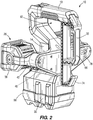
FIG. 2 is a rear perspective view of the utility mount light. -
FIG. 3 is a front view of the utility mount light. -
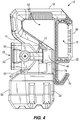
FIG. 4 is a side view of the utility mount light. -
FIG. 5 is a rear view of the utility mount light. -
FIG. 6 is a second front perspective view with a door of a battery support portion of the utility mount light removed. -
FIG. 7 is a side view of a cross section taken along line 7-7 inFIG. 5 . -
FIG. 8 is a perspective view of the utility mount light with the handle in an open or extended position. - Before any embodiments of the invention are explained in detail, it is to be understood that the invention is not limited in its application to the details of construction and the arrangement of components set forth in the following description or illustrated in the following drawings. The invention is capable of other embodiments and of being practiced or of being carried out in various ways. Also, it is to be understood that the phraseology and terminology used herein is for the purpose of description and should not be regarded as limiting.
-
FIGS. 1-5 illustrate autility mount light 10 including amain housing 14, ahandle portion 18 supporting ahandle 22, a pair of rotatable light head assemblies 26, and abattery support portion 30 configured to detachably couple a battery pack (not shown). As explained in greater detail below, theutility mount light 10 is configured to be attached to a bucket of an elevated work platform (i.e., boom lift, man lift, basket crane, hydraladder, cherry picker, etc.), other components such as tables, or to a workpiece using thehandle 22. For convenience, the component to which thelight 10 attaches will hereinafter be referred to as a workpiece. Once thelight 10 is mounted to the workpiece, the rotatable light head assemblies 26 may be rotated as desired to illuminate a work area. - With reference to
FIG. 1 and2 , thelight assemblies 26 each include alight housing 38 that is pivotally coupled between two opposed arms of ayoke 42 for pivoting motion about a first pivot axis A such that a direction of thelight housing 38 is adjustable by a user. Each of thelight housings 38 is independently rotatable to enhance the ability to direct the light as desired. In one embodiment, a pivoting range of thelight housing 38 within theyoke 42 may be limited to approximately 180° about the first pivot axis A (e.g., via stops within the yoke 42). In another embodiment, thelight housing 38 may pivot 360° about the first pivot axis A within theyoke 42. In other embodiments, thelight housing 38 may have a discrete pivot range about the first pivot axis A within the yoke 42 (e.g., any discrete pivot range between 0-360°). - The
yoke 42 is further coupled to themain housing 14 via ajoint 46 that may be rotatable about a second pivot axis B that is orthogonal to the first pivot axis A such that a rotational orientation of theyoke 42 is adjustable by a user. In some embodiments, theyoke 42 is coupled to the main housing via ajoint 46 that is rotatable 360° about the second pivot axis B. In other embodiments, theyoke 42 is coupled to themain housing 14 via ajoint 46 that limits rotation (e.g., using stops in the joint 46). For example, rotation may be limited to discrete angles less than 360° but more than 180°, or rotation may be limited to discrete angles less than 180°. These configurations allow the light assemblies 26 to be directed in a variety of directions and orientations, and also allow the light assemblies 26 to be movable independently of one another. - In one embodiment, the
light housing 38 may be fixed within the yoke 42 (i.e., the light housing is not pivotable) while theyoke 42 is rotatably coupled to themain housing 14 via ajoint 46 that permits rotation as described above. In another embodiment, theyoke 42 may be fixedly coupled to the main housing 14 (i.e., theyoke 42 is not rotatable) while thelight housing 38 is pivotable within theyoke 42 as described above. In yet another embodiment, thelight housing 38 may be fixed within the yoke 42 (i.e., the light housing is not pivotable) and theyoke 42 may be fixedly coupled to the main housing 14 (i.e., theyoke 42 is not rotatable). - As seen in
FIG. 3 , thelight assemblies 26 are disposed on opposing sides of themain housing 14 and thebattery support portion 30. - The
light housings 38 further support a plurality of lights. The lights may be, for example, spot LEDs, flood LEDs, a fluorescent bulb, an incandescent bulb, or any other suitable lighting elements. In a preferred embodiment, the lights supported within thelight housing 30 are a combination of multiple spot LEDs and/or multiple flood LEDs configured to be operated separately and/or in tandem. The lights may be surrounded by a light guide disposed within the housing that directs light throughlenses 50 of thelight assemblies 26. - With reference to
FIGS. 1 and6 , thebattery support portion 30 is formed as one piece with themain housing 14 and is configured to detachably couple the battery pack. In the illustrated embodiment, thebattery support portion 30 defines acavity 54 for receiving the battery pack (FIG. 6 ). Adoor 58 is pivotally coupled to thebattery support portion 30 at an open end of the cavity, and is releasably secured to the casing via alatch 62. Thedoor 58 is further configured to sealingly engage the open end of the cavity such that, when the battery pack is secured within thecavity 54, no water or contaminants may enter thecavity 54. The sealed engagement may be accomplished by, for example, providing a gasket, an O-ring, a deformable member, or other sealing member to one or both of thebattery support portion 30 and thedoor 58. In preferred constructions, the battery pack is a power tool battery pack. - With reference to
FIG. 1 , thehandle portion 18 includes a power actuator, a first mode actuator, and a second mode actuator (e.g., buttons, trigger switches, knobs, etc.). Each of the actuators may be coupled to a processor supported within theutility mount light 10. The processor is coupled to the lights within each of thelight housings 38 and to the battery pack control to the power supplied by the battery pack to each of the light assemblies. In some constructions, some or all of the actuators may be virtual controls (e.g., touch screens) rather than real buttons, switches, or knobs. - The processor is implemented as a microprocessor including a non-transitory, computer-readable memory that stores executable instructions to carry out functionalities of the
utility mount light 10. The processor 12 may be implemented partially or entirely as, for example, a field-programmable gate array (FPGA), and application specific integrated circuit (ASIC). - The power actuator may be operated by a user to simultaneously turn both
light assemblies 26 on or off. The first mode actuator may be successively operated by a user to cycle one of the light assemblies 26 through a plurality of modes, and the second mode actuator may be successively operated by a user to cycle theother light assembly 26 through the plurality of modes. The plurality of modes may include, for example, a spot mode in which spot LEDs are activated, a flood mode in which flood LEDs are activated, spot/flood mode in which both spot LEDs and flood LEDs are activated, and an off mode (i.e., such that eachlight assembly 26 may be independently turned off). In one embodiment, the plurality of modes may further include brightness modes for one or more of the spot mode, the flood mode, and the spot/flood mode. In another embodiment, the plurality of modes may be a multiple discrete brightness modes (e.g., low/medium/high, etc.). - In another embodiment, the
utility mount light 10 may include separate power actuators for each light, such that there is a first power actuator, a second power actuator, a first mode switch, and a second mode switch. In such an embodiment, the first power actuator controls the on/off state of one of thelight assemblies 26, while the second power actuator controls the on/off state of the otherlight assembly 26. - In yet another embodiment, the utility mount light may include a first actuator and a second actuator. In this embodiment, the first actuator is configured to operate one of the
light assemblies 26 while the second actuator is configured to operate the other light assembly. The first actuator may be successively operated by a user to turn thelight assembly 26 on, cycle thelight assembly 26 through a plurality of modes, and turn thelight assembly 26 off. The second actuator may be successively operated by a user to turn the otherlight assembly 26 on, cycle the otherlight assembly 26 through a plurality of modes, and turn the otherlight assembly 26 off. - In any of the embodiments described above, it should be clear that each
light assembly 26 may be individually operated (i.e., turned on/off) and/or individually cycled through the plurality of modes such that thelight assemblies 26 may be in independent operating states. - With reference to
FIGS. 2 and4 , thehandle 22 includes a grippingportion 66 defined by anaperture 70 extending through thehandle 22, and ahook portion 74 adjacent the grippingportion 66. Thehandle 22 is movably coupled to thehandle portion 18 at an end adjacent the grippingportion 66, and is biased by a constant force or a clock spring 86 (FIG. 7 ) toward a closed position (FIG. 4 )where thehandle 22 maintains contact with a workpiece and/or an opposingsupport surface 78 disposed on themain housing 14. However, in other embodiments, other biasing members such as a torsion spring, a helical spring, or an adjustable spiral spring, among others, may be used in place of or in conjunction with theconstant force spring 86. Thehandle 22 is movable in a linear direction to an open or extended position (FIG. 8 ) away from the support surface 78 (i.e., thehandle 22 is linearly extensible). In addition, when thehandle 22 is extended away from thesupport surface 78, anopening 82 is defined between thehandle portion 18, thehandle 22, and themain housing 14. Theopening 82 is configured to receive a portion or a lip of the work platform (i.e., boom lift, man lift, basket crane, hydraladder, cherry picker, etc.) or the workpiece. In addition, the size of theopening 82 is such that it can receive a variety of differently sized lips. - In operation, the
utility mount light 10 may be attached to a work platform or a workpiece using thehandle 22. A user may grasp the grippingportion 66 and themain housing 14, for example, and pull thehandle 22 against the bias of theconstant force spring 86 toward the open position to disengage contact between thehandle 22 and thesupport surface 78 to create a gap. Thehandle 22 andsupport surface 78 may then be placed on opposing sides of a workpiece or a work platform (i.e., a bucket, etc.) and subsequently released such that the bias of theconstant force spring 86 pulls thehandle 22 toward thesupport surface 78 to clamp the work platform or workpiece between thehandle 22 and thesupport surface 78. In one embodiment, the movable range of thehandle 22 may be limited such that the maximum gap is approximately 3.5 inches. - The
utility mount light 10 may be detached from a work platform or workpiece by pulling thehandle 22 against the bias of theconstant force spring 86 to open a gap between the work platform or workpiece and thehandle 22 and/or the support surface 78 (i.e., un-clamp theutility mount light 10 form the work platform or workpiece). However, pulling thehandle 22 may not be required in some embodiments. For example, the biasing force of theconstant force spring 86 may be set such that thespring 86 retracts the handle and provides the desired clamping/frictional force on the work platform or workpiece, but allows the user to detach the utility mount light 10 from the work platform or workpiece by grasping thehandle portion 18 and lifting theutility mount light 10 away from the workpiece. Using this method, a user can remove the light 10 with one hand by simply grasping thehandle portion 18 and pulling the light upward. - It should be noted that the placement of the gripping
portion 66 of thehandle 22 adjacent to thehandle portion 18 provides certain advantages. This placement reduces the distance between a grippingportion 66 and the spring, thereby reducing rotational torqueing on thehandle 22 and the spring during operation thereby increasing the operational life. - In addition, the linearly
displaceable handle 22 advantageously allows theutility light 10 to be coupled to work platforms or workpieces of various sizes (e.g., various widths). - Various features of the invention are set forth in the following paragraphs and the claims that follow.
- An aspect of the invetion provides a utility light comprising: a main body; a light assembly defined on the main body including a light source disposed within a light housing, the light housing being pivotable and rotatable relative to the main body; and a handle movably coupled to the main body, the handle being configured to engage a workpiece to support the utility light on the workpiece.
- The light assembly may be a first light assembly, and the main body may further include a second light assembly defined on the main body including a second light source disposed within a second light housing, the second light housing optinally being pivotable and rotatable relative to the main body.
- The light housing may be supported for pivoting movement within a yoke that is rotatably coupled to the main body. The yoke may be rotatable 180 degrees relative to the main body.
- The handle may be linearly extensible relative to the main body and may be biased toward the main body such that the handle may be configured to clamp a workpiece between the handle and the main body. The handle may be biased by a constant force spring.
- The utility light may further include a battery support portion defined on the main body configured to receive a battery that may provide power to the light source.
- Another aspect of the invention provides a utility light comprising: a main body; a first light assembly defined on the main body including a first light source disposed within a first light housing, the first light housing being pivotable and rotatable relative to the main body; a second light assembly defined on the main body including a second light source disposed within a second light housing, the second light housing being pivotable and rotatable relative to the main body; and a handle including a portion that is movably coupled to the main body, the handle being configured to engage a workpiece to support the utility light on the workpiece.
- The first light assembly and the second light assembly may be disposed on opposing sides of the main body.
- The first light housing may be pivotally supported between opposed arms of a first yoke that may be rotatably coupled to the main body. The second light housing may be pivotally supported between opposed arms of a second yoke that may be rotatably coupled to the main body. Each of the first yoke and the second yoke may be rotatable 180 degrees relative to the main body.
- The handle may be linearly extensible relative to the main body and may be biased towards the main body by a constant force spring.
- The first light source may include a first plurality of LEDs and the second light source may include a second plurality of LEDs.
- A further aspect of the invention provides a utility light comprising: a main body; a handle movably coupled to the main body, the handle being biased toward the main body such that the handle is configured to clamp a workpiece between the main body and the handle; a first light assembly defined on the main body including a first light source disposed within a first light housing, the first light housing being pivotally supported within a first yoke that is rotatable relative to the main body; and a second light assembly defined on the main body including a second light source disposed within a second light housing, the second light housing being pivotally supported within a second yoke that is rotatable relative to the main body.
- The utility light may further include a battery support portion that may receive a battery configured to provide power to each of the first light assembly and the second light assembly. The battery support portion may extend from the main body between the first light assembly and the second light assembly.
- The first light source may include a first plurality of LEDs and the second light source may include a second plurality of LEDs.
- The handle may be linearly extensible relative to the main body.
- The handle may be biased toward the main body by a constant force spring.
- The first light assembly and the second light assembly may be disposed on opposite sides of the main body.
Claims (15)
- A utility light comprising:a main body;a light assembly defined on the main body including a light source disposed within a light housing, the light housing being pivotable and rotatable relative to the main body; anda handle movably coupled to the main body, the handle being configured to engage a workpiece to support the utility light on the workpiece.
- The utility light of claim 1, wherein the light assembly is a first light assembly, and the main body further includes a second light assembly defined on the main body including a second light source disposed within a second light housing, the second light housing being pivotable and rotatable relative to the main body.
- The utility light of claim 1, wherein the light housing is supported for pivoting movement within a yoke that is rotatably coupled to the main body, optionally wherein the yoke is rotatable 180 degrees relative to the main body.
- The utility light of claim 1, wherein the handle is linearly extensible relative to the main body and is biased toward the main body such that the handle is configured to clamp a workpiece between the handle and the main body, optionally wherein the handle is biased by a constant force spring.
- The utility light of claim 1, further including a battery support portion defined on the main body configured to receive a battery that provides power to the light source.
- A utility light comprising:a main body;a first light assembly defined on the main body including a first light source disposed within a first light housing, the first light housing being pivotable and rotatable relative to the main body;a second light assembly defined on the main body including a second light source disposed within a second light housing, the second light housing being pivotable and rotatable relative to the main body; anda handle including a portion that is movably coupled to the main body, the handle being configured to engage a workpiece to support the utility light on the workpiece.
- The utility light of claim 6, wherein the first light assembly and the second light assembly are disposed on opposing sides of the main body.
- The utility light of claim 6, wherein the first light housing is pivotally supported between opposed arms of a first yoke that is rotatably coupled to the main body, and the second light housing is pivotally supported between opposed arms of a second yoke that is rotatably coupled to the main body, optionally wherein each of the first yoke and the second yoke are rotatable 180 degrees relative to the main body.
- The utility light of claim 6, wherein the handle is linearly extensible relative to the main body and is biased towards the main body by a constant force spring.
- The utility light of claim 6, wherein the first light source includes a first plurality of LEDs and the second light source includes a second plurality of LEDs.
- A utility light comprising:a main body;a handle movably coupled to the main body, the handle being biased toward the main body such that the handle is configured to clamp a workpiece between the main body and the handle;a first light assembly defined on the main body including a first light source disposed within a first light housing, the first light housing being pivotally supported within a first yoke that is rotatable relative to the main body; anda second light assembly defined on the main body including a second light source disposed within a second light housing, the second light housing being pivotally supported within a second yoke that is rotatable relative to the main body.
- The utility light of claim 11, further including a battery support portion that receives a battery configured to provide power to each of the first light assembly and the second light assembly, optionally wherein the battery support portion extends from the main body between the first light assembly and the second light assembly.
- The utility light of claim 11, wherein the first light source includes a first plurality of LEDs and the second light source includes a second plurality of LEDs.
- The utility light of claim 11, wherein the handle is linearly extensible relative to the main body, optionally wherein the handle is biased toward the main body by a constant force spring.
- The utility light of claim 11, wherein the first light assembly and the second light assembly are disposed on opposite sides of the main body.
Applications Claiming Priority (1)
| Application Number | Priority Date | Filing Date | Title |
|---|---|---|---|
| US201562255078P | 2015-11-13 | 2015-11-13 |
Publications (2)
| Publication Number | Publication Date |
|---|---|
| EP3168523A1 true EP3168523A1 (en) | 2017-05-17 |
| EP3168523B1 EP3168523B1 (en) | 2019-04-10 |
Family
ID=57354122
Family Applications (1)
| Application Number | Title | Priority Date | Filing Date |
|---|---|---|---|
| EP16198619.5A Active EP3168523B1 (en) | 2015-11-13 | 2016-11-14 | Utility mount light |
Country Status (4)
| Country | Link |
|---|---|
| US (10) | US10323831B2 (en) |
| EP (1) | EP3168523B1 (en) |
| CN (1) | CN206377493U (en) |
| TW (1) | TWM542110U (en) |
Cited By (3)
| Publication number | Priority date | Publication date | Assignee | Title |
|---|---|---|---|---|
| EP3187771A1 (en) * | 2015-12-10 | 2017-07-05 | Milwaukee Electric Tool Corporation | Flood light |
| US11879603B2 (en) | 2019-11-22 | 2024-01-23 | Milwaukee Electric Tool Corporation | Work light |
| USD1032902S1 (en) | 2020-06-22 | 2024-06-25 | Milwaukee Electric Tool Corporation | Work light |
Families Citing this family (17)
| Publication number | Priority date | Publication date | Assignee | Title |
|---|---|---|---|---|
| US10323831B2 (en) | 2015-11-13 | 2019-06-18 | Milwaukee Electric Tool Corporation | Utility mount light |
| USD816252S1 (en) * | 2016-05-16 | 2018-04-24 | Milwaukee Electric Tool Corporation | Light |
| CN110375216A (en) * | 2018-04-11 | 2019-10-25 | 宁波金利达灯饰有限公司 | It is hand-holdable to turn over conjunction lamp |
| US11408593B2 (en) * | 2020-05-28 | 2022-08-09 | Klein Tools, Inc. | Lighting device for an aerial work platform |
| US11187401B1 (en) * | 2020-05-28 | 2021-11-30 | Klein Tools, Inc. | Lighting device for an aerial work platform |
| USD957711S1 (en) * | 2020-08-20 | 2022-07-12 | Ningbo Taller Electrical Appliance Co., Ltd. | Work light |
| WO2022067072A1 (en) * | 2020-09-24 | 2022-03-31 | Milwaukee Electric Tool Corporation | Portable lighting systems |
| USD980487S1 (en) * | 2021-01-26 | 2023-03-07 | Astera Manufacturing Limited | Lamp |
| US11162649B1 (en) * | 2021-02-05 | 2021-11-02 | Streamlight, Inc. | Portable light having a movable head and/or a movable handle |
| CN215174276U (en) * | 2021-06-16 | 2021-12-14 | 宁波天瑞电器有限公司 | Hand-held type spotlight |
| US20230027574A1 (en) * | 2021-07-26 | 2023-01-26 | Makita Corporation | Striking tool |
| US12385630B2 (en) | 2022-05-24 | 2025-08-12 | Black & Decker Inc. | Portable flashlight |
| US12196380B2 (en) | 2022-05-24 | 2025-01-14 | Black & Decker Inc. | Portable illumination apparatus |
| USD1140154S1 (en) * | 2022-12-07 | 2026-08-04 | Energizer Brands, Llc | Lighting device |
| USD1090939S1 (en) * | 2023-01-13 | 2025-08-26 | Streamlight, Inc. | Lighting device |
| USD1043523S1 (en) * | 2023-06-29 | 2024-09-24 | Autel Robotics Co., Ltd. | Megaphone and searchlight integrated device of aircraft |
| USD1089765S1 (en) * | 2025-04-04 | 2025-08-19 | Guangdong Bravo New Energy Technology Co. LTD. | Triple-head lamp |
Citations (4)
| Publication number | Priority date | Publication date | Assignee | Title |
|---|---|---|---|---|
| US20090116230A1 (en) * | 2007-11-05 | 2009-05-07 | Wei Young | Dual light source utility light |
| US20090284963A1 (en) * | 2008-05-15 | 2009-11-19 | Air Systems, Inc. Dba Air Systems International, Inc. | Collapsible portable stand with telescoping support and integral storage case |
| GB2468740A (en) * | 2009-03-20 | 2010-09-22 | Stanley Works | Flashlight |
| US20140126192A1 (en) * | 2012-11-08 | 2014-05-08 | Blackbeam Llc | Worklight with integrated clamp handle |
Family Cites Families (279)
| Publication number | Priority date | Publication date | Assignee | Title |
|---|---|---|---|---|
| US3331958A (en) | 1964-05-04 | 1967-07-18 | Alan J Adler | Portable fluorescent lamp |
| US4032771A (en) | 1973-02-06 | 1977-06-28 | Original Hanau Quarzlampen Gmbh | Surgical operating lamp |
| US3973179A (en) | 1974-08-23 | 1976-08-03 | The Black And Decker Manufacturing Company | Modular cordless tools |
| US4228489A (en) | 1979-03-01 | 1980-10-14 | Martin Edward D | Portable stand apparatus for electric flood lights |
| US4268894A (en) | 1979-03-05 | 1981-05-19 | Duracell International Inc. | Portable waterproof fluorescent lantern |
| US4324477A (en) | 1980-11-18 | 1982-04-13 | Kabushiki Kaisha L.P.L | Photographic tripod apparatus |
| DE3508035A1 (en) | 1985-03-07 | 1986-09-18 | Thomas, Rudolf, 5200 Siegburg | HOLLOW BODY MAST WITH TRANSPORT BASKET |
| US5019951A (en) * | 1989-11-28 | 1991-05-28 | Rayovac Corporation | Spotlight with adjustable handle |
| US5207747A (en) | 1991-04-12 | 1993-05-04 | Musco Corporation | Mobile lighting system |
| US5203621A (en) | 1992-04-10 | 1993-04-20 | Super Vacuum Manfacturing Co., Inc. | Roof-mounted flood light assembly |
| US5351172A (en) | 1993-03-08 | 1994-09-27 | Attree Russell C | Back-lighted display panel for coolers |
| US5400234A (en) | 1994-03-09 | 1995-03-21 | Yu; Abraham | Light |
| US5428520A (en) | 1994-08-03 | 1995-06-27 | Skief; Mark W. | Adjustable protable utility light stand |
| USD376535S (en) | 1995-10-06 | 1996-12-17 | Industrial Molding Corporation | Articulated decorative light support bracket |
| US5630660A (en) | 1996-05-16 | 1997-05-20 | Chen; Wei-Fu | Warning light |
| US6045240A (en) | 1996-06-27 | 2000-04-04 | Relume Corporation | LED lamp assembly with means to conduct heat away from the LEDS |
| US5944407A (en) | 1996-07-26 | 1999-08-31 | Eveready Battery Company, Inc. | Flashlight/area table lamp having a flexible neck |
| US5934628A (en) | 1997-01-23 | 1999-08-10 | Bosnakovic; Frederick | Portable vertical support |
| USD392065S (en) * | 1997-05-21 | 1998-03-10 | Coleman Safety And Security Products, Inc. | Security lighting fixture |
| US5964524A (en) | 1998-01-22 | 1999-10-12 | Regent Lighting Corporation | Worklight with stand |
| US6183114B1 (en) | 1998-05-28 | 2001-02-06 | Kermit J. Cook | Halogen torchiere light |
| US6213626B1 (en) | 1998-06-05 | 2001-04-10 | Regent Lighting Corporation | Convertible worklight |
| USD422203S (en) | 1998-06-19 | 2000-04-04 | Gary Lonnie F | Combination clip for icicle lights |
| DE29811569U1 (en) | 1998-06-29 | 1998-10-08 | Liu, Chen-An, Da-Jia, Taichung | Multi-purpose lamp |
| US6092911A (en) | 1998-10-05 | 2000-07-25 | F. M. Brick Industries, Inc. | Apparatus and method for illuminating the scene of an emergency |
| US6149283A (en) | 1998-12-09 | 2000-11-21 | Rensselaer Polytechnic Institute (Rpi) | LED lamp with reflector and multicolor adjuster |
| USD424418S (en) | 1999-06-14 | 2000-05-09 | Gary Products Group, Inc. | Icicle light support clip |
| US6367949B1 (en) | 1999-08-04 | 2002-04-09 | 911 Emergency Products, Inc. | Par 36 LED utility lamp |
| USD438998S1 (en) * | 1999-08-09 | 2001-03-13 | Steinel Gmbh & Co. Kg | Halogen motion detection security light positioning system |
| USD428176S (en) | 1999-08-10 | 2000-07-11 | The Coleman Company, Inc. | Portable light |
| US6379023B1 (en) | 1999-08-31 | 2002-04-30 | Edward Passno | Light assembly for an electrically insulated lift bucket |
| US6461017B2 (en) | 1999-11-19 | 2002-10-08 | Tom V. Selkee | Marker light |
| CA2296859A1 (en) | 2000-01-21 | 2001-07-21 | Hung-Ming Shih | Warning device for motor vehicle |
| US6255786B1 (en) | 2000-04-19 | 2001-07-03 | George Yen | Light emitting diode lighting device |
| GB2364948B (en) * | 2000-05-10 | 2002-09-04 | John Mfg Ltd | Lantern |
| DE10023183A1 (en) | 2000-05-11 | 2001-11-15 | Stefan Lohwasser | Underwater light for divers has several housing sections with power sources which can be joined together to vary available power |
| DE10055264A1 (en) | 2000-11-08 | 2002-05-23 | Still Gmbh | Industrial truck with a lifting device and a work light |
| GB0029254D0 (en) | 2000-11-30 | 2001-01-17 | Wolfe Designs Ltd | Retractable towers |
| US20020126492A1 (en) | 2001-01-03 | 2002-09-12 | Yueh Ching | Work light stand |
| USD452022S1 (en) | 2001-02-01 | 2001-12-11 | Eveready Battery Company, Inc. | Lantern |
| US20020136005A1 (en) | 2001-03-26 | 2002-09-26 | Lee Dong H. | Emergency flashlight with a stand |
| US6554459B2 (en) | 2001-03-28 | 2003-04-29 | Lowel-Light Manufacturing, Inc. | Support bracket for light stand |
| US20020167814A1 (en) | 2001-04-10 | 2002-11-14 | Yueh Ching | Portable work light |
| US6474844B1 (en) | 2001-04-10 | 2002-11-05 | Test-Rite Products Corporation | Stand with work light that can be directed at multiple positions |
| US6857756B2 (en) | 2001-04-11 | 2005-02-22 | General Manufacturing, Inc. | LED work light |
| US6824297B1 (en) | 2001-08-10 | 2004-11-30 | Eml Technologies Llc | Portable worklight assembly |
| US6926428B1 (en) | 2001-10-25 | 2005-08-09 | Eml Technologies Llc | Worklight case |
| US6953260B1 (en) * | 2001-11-16 | 2005-10-11 | Allen David M | Convertible flashlight-headlamp |
| USD494849S1 (en) | 2002-01-15 | 2004-08-24 | Emerald Innovations, L.L.C. | Decorative light support clip |
| US20030137847A1 (en) | 2002-01-23 | 2003-07-24 | Roston Cooper | Portable telescoping light stand |
| US6637904B2 (en) | 2002-02-25 | 2003-10-28 | Refugio E. Hernandez | Wireless quick release lighting system with supports, mounting brackets, lights, and accessories |
| CN2562065Y (en) | 2002-03-12 | 2003-07-23 | 特力股份有限公司 | Tool light stand |
| US7153004B2 (en) | 2002-12-10 | 2006-12-26 | Galli Robert D | Flashlight housing |
| US6873249B2 (en) | 2002-12-31 | 2005-03-29 | Wu-Lung Chu | Luminous alarm device |
| US6854862B1 (en) | 2003-01-24 | 2005-02-15 | Steven L. Hopf | Adjustable light |
| US6877881B2 (en) | 2003-05-14 | 2005-04-12 | Frank Tsao | Worklight |
| US7008072B2 (en) | 2003-05-15 | 2006-03-07 | Onward Multi-Corp Inc. | Light for barbecue grill |
| US6802623B1 (en) | 2003-05-20 | 2004-10-12 | Techway Industrial Co., Ltd. | Light seat for a portable light with an adjustment capability for a light fixture |
| US7001047B2 (en) | 2003-06-10 | 2006-02-21 | Illumination Management Solutions, Inc. | LED light source module for flashlights |
| US7073926B1 (en) | 2003-06-30 | 2006-07-11 | Kremers Bernard J | Adjustable overhead trouble light stand |
| US6899441B2 (en) | 2003-08-04 | 2005-05-31 | Hsiu Chin Chen | Multifunction warning device |
| US7001044B2 (en) | 2003-08-08 | 2006-02-21 | Leen Monte A | Multiple head worklight |
| US6902294B2 (en) | 2003-08-13 | 2005-06-07 | Michael N. Wright | Light stand |
| AU2004226925A1 (en) | 2003-11-03 | 2005-05-19 | Black & Decker, Inc. | Tripod assembly |
| US7063444B2 (en) | 2004-02-17 | 2006-06-20 | Eml Technologies Llc | Omni-directional worklight |
| US7194358B2 (en) | 2004-02-25 | 2007-03-20 | The Boeing Company | Lift collision avoidance system |
| US20050201085A1 (en) | 2004-03-11 | 2005-09-15 | Takamine Aikawa | Telescopic flashlight |
| US7503530B1 (en) | 2004-05-11 | 2009-03-17 | Lonnie Ray Brown | Lighting stand |
| TWM264427U (en) | 2004-06-24 | 2005-05-11 | Shiun-Teng Wang | Illuminant alarm device with a directing function |
| US7192160B2 (en) | 2004-07-12 | 2007-03-20 | General Manufacturing, Inc. | Light fixture |
| USD506847S1 (en) | 2004-07-21 | 2005-06-28 | Rally Manufacturing, Inc. | Spot light |
| US7293898B2 (en) | 2004-07-29 | 2007-11-13 | Princeton Tectonics, Inc. | Portable light |
| CN1731003A (en) | 2004-08-05 | 2006-02-08 | 明辉光源科技(深圳)有限公司 | Photoelectron ultra-strong light source portable lamp |
| US7342360B2 (en) | 2004-10-20 | 2008-03-11 | The Stanley Works | Flashlight |
| GB0512256D0 (en) | 2005-06-16 | 2005-07-27 | Fowler James A | Lighting device |
| US20060146550A1 (en) | 2004-12-30 | 2006-07-06 | Simpson Charlie L | Fixture-holding component, light fixture and pole light including the same |
| USD529360S1 (en) | 2005-03-14 | 2006-10-03 | Roger Wimmer | Tool handle |
| US7621652B2 (en) | 2005-03-31 | 2009-11-24 | Milwaukee Electric Tool Corporation | Electrical component, such as a lighting unit and battery charger assembly |
| USD529926S1 (en) | 2005-04-26 | 2006-10-10 | Vector Products, Inc. | Combined air compressor, inflator, and spotlight |
| US7195377B2 (en) | 2005-06-09 | 2007-03-27 | Peter Tsai | Worklight support with stand |
| US20060279948A1 (en) | 2005-06-09 | 2006-12-14 | Peter Tsai | Worklight support with stand |
| US7350940B2 (en) | 2005-08-03 | 2008-04-01 | Ruud Lighting, Inc. | Overhead industrial light fixture with thermal chimney contiguous to recessed socket |
| US7152997B1 (en) | 2005-10-04 | 2006-12-26 | Alert Safety Lite Products Co., Inc. | LED utility light with stand |
| USD549859S1 (en) | 2005-10-04 | 2007-08-28 | Alert Safety Lite Products Co., Inc | LED utility light with stand |
| US7278761B2 (en) | 2005-10-06 | 2007-10-09 | Thermalking Technology International Co. | Heat dissipating pole illumination device |
| USD532536S1 (en) | 2005-11-01 | 2006-11-21 | Vector Products, Inc. | TV lamp |
| TW200722677A (en) | 2005-12-09 | 2007-06-16 | Wen-Chin Shiau | Heat dissipation structure for blaze flashlight |
| USD551048S1 (en) | 2006-01-19 | 2007-09-18 | Yin Han Huang | Saw frame |
| USD551532S1 (en) | 2006-01-19 | 2007-09-25 | Yin Han Huang | Saw frame |
| USD553783S1 (en) * | 2006-01-20 | 2007-10-23 | Lmt-Mercer Group Inc. | Solar wedge light |
| USD538636S1 (en) | 2006-02-03 | 2007-03-20 | Emerald Innovation L.L.C. | Clip |
| USD537330S1 (en) | 2006-02-03 | 2007-02-27 | Emerald Innovation L.L.C. | Clip |
| US7618154B2 (en) | 2006-02-07 | 2009-11-17 | Rosiello Keith M | Compact reconfigurable illumination device |
| US20070211470A1 (en) | 2006-03-03 | 2007-09-13 | Hsien-Jung Huang | Lamp house with heat sink |
| CA2541640C (en) | 2006-03-08 | 2010-07-20 | Sumac Fabrication Co. Ltd. | Temporary lighting support assembly for scaffolding systems |
| US7638970B1 (en) | 2006-05-31 | 2009-12-29 | Golight, Inc. | Search light with remote charger |
| USD556353S1 (en) | 2006-05-31 | 2007-11-27 | Gebhard Albert W | Searchlight with charging station |
| US7524079B2 (en) | 2006-06-23 | 2009-04-28 | William John Greenhoe | Solar rechargeable lantern |
| USD553771S1 (en) | 2006-08-23 | 2007-10-23 | Black & Decker Inc. | Worklight |
| US9188320B2 (en) | 2006-10-09 | 2015-11-17 | Genlyte Thomas Group, Llc | Luminaire junction box |
| EP2084452B1 (en) | 2006-11-14 | 2016-03-02 | Cree, Inc. | Lighting assemblies and components for lighting assemblies |
| CN101210664A (en) | 2006-12-29 | 2008-07-02 | 富准精密工业(深圳)有限公司 | Light-emitting diode lamps and lanterns |
| TW200829831A (en) | 2007-01-04 | 2008-07-16 | Wen-Chin Shiau | Heat dissipation device of a LED lamp with high wattage |
| USD553461S1 (en) | 2007-02-07 | 2007-10-23 | Gabe Neiser | Electric scissor |
| US7618153B2 (en) | 2007-02-15 | 2009-11-17 | Black & Decker, Inc. | Flashlight with rotatable handle |
| USD553281S1 (en) | 2007-02-27 | 2007-10-16 | Eveready Battery Company, Inc. | Flashlight |
| US7484858B2 (en) | 2007-03-28 | 2009-02-03 | Pelican Products, Inc. | Lighting system |
| US7470036B2 (en) | 2007-03-28 | 2008-12-30 | Pelican Products, Inc. | Lighting system |
| US7798684B2 (en) | 2007-04-06 | 2010-09-21 | Genlyte Thomas Group Llc | Luminaire system with thermal chimney effect |
| US7581856B2 (en) | 2007-04-11 | 2009-09-01 | Tamkang University | High power LED lighting assembly incorporated with a heat dissipation module with heat pipe |
| PT2153115T (en) | 2007-05-04 | 2021-09-06 | Signify Holding Bv | Led-based fixtures and related methods for thermal management |
| US20080302933A1 (en) | 2007-06-08 | 2008-12-11 | Cardellini Steven L | Mount for motion picture lights in aerial lifts |
| TW200925493A (en) | 2007-09-14 | 2009-06-16 | Anteya Technology Corp | Strip-lamp-type LED street lamp |
| CN101392899B (en) | 2007-09-21 | 2012-01-11 | 富士迈半导体精密工业(上海)有限公司 | LED lamp with heat radiation structure |
| US7572024B2 (en) | 2007-10-16 | 2009-08-11 | Elumx, Llc | Variably-adjustable grill light and method of use thereof |
| CN101440949A (en) | 2007-11-23 | 2009-05-27 | 富准精密工业(深圳)有限公司 | Heat radiating device |
| US20090134191A1 (en) | 2007-11-28 | 2009-05-28 | Michael Phillips | Power tool with hook |
| JP2011507152A (en) | 2007-12-07 | 2011-03-03 | オスラム ゲゼルシャフト ミット ベシュレンクテル ハフツング | Heat sink and lighting device including heat sink |
| CN101451695A (en) | 2007-12-07 | 2009-06-10 | 富准精密工业(深圳)有限公司 | LED lamp |
| USD593236S1 (en) | 2008-01-08 | 2009-05-26 | Black & Decker Inc. | Worklamp |
| US7972036B1 (en) | 2008-04-30 | 2011-07-05 | Genlyte Thomas Group Llc | Modular bollard luminaire louver |
| US7857486B2 (en) | 2008-06-05 | 2010-12-28 | Fu Zhun Precision Industry (Shen Zhen) Co., Ltd. | LED lamp assembly having heat pipes and finned heat sinks |
| CN100580308C (en) | 2008-06-06 | 2010-01-13 | 广州市雅江光电设备有限公司 | Split LED lamps |
| DE112009001556T5 (en) | 2008-06-23 | 2011-04-28 | Milwaukee Electric Tool Corp., Brookfield | Electrical arrangement with a battery charging function |
| CN101614325B (en) | 2008-06-27 | 2012-02-08 | 富准精密工业(深圳)有限公司 | Semiconductor illumination device |
| US8087797B2 (en) | 2008-07-18 | 2012-01-03 | Stanley Black & Decker, Inc. | Illumination device with detachable light sources |
| TWM348905U (en) | 2008-07-29 | 2009-01-11 | wei-hong Luo | High power LED (light emitting diode) light source structure with uniform illumination and high efficiency heat dissipation |
| US20100027260A1 (en) | 2008-07-30 | 2010-02-04 | Lustrous International Technology Ltd. | Light emitting diode lamp |
| USD595105S1 (en) | 2008-08-05 | 2009-06-30 | James Dale White | Vehicle escape tool |
| CN101676628B (en) | 2008-09-19 | 2012-09-19 | 富准精密工业(深圳)有限公司 | Light emitting diode lamp |
| US7914182B2 (en) | 2008-09-30 | 2011-03-29 | GE Lighting Soutions, LLC | Decorative light fixture including cooling system |
| US20100142213A1 (en) | 2008-09-30 | 2010-06-10 | Cooper Technologies Company | Methods And Apparatus For Enhancing Portable Worklight Features |
| EP2172693B1 (en) | 2008-10-01 | 2015-05-20 | Enel Sole S.r.L. | Lighting device with optimized emission |
| US8123382B2 (en) | 2008-10-10 | 2012-02-28 | Cooper Technologies Company | Modular extruded heat sink |
| US8881411B2 (en) | 2008-11-28 | 2014-11-11 | Irwin Industrial Tool Company | Hacksaw with blade tensioning mechanism |
| US8007145B2 (en) | 2008-12-11 | 2011-08-30 | Leen Monte A | Worklight with a hands-free mounting system |
| CN101769524B (en) | 2009-01-06 | 2012-12-26 | 富准精密工业(深圳)有限公司 | Light emitting diode lamp and light engine thereof |
| CN101776254B (en) | 2009-01-10 | 2012-11-21 | 富准精密工业(深圳)有限公司 | Light emitting diode lamp and photo engine thereof |
| US8366290B2 (en) | 2009-01-14 | 2013-02-05 | Mag Instrument, Inc. | Portable lighting device |
| US8328398B2 (en) | 2009-01-20 | 2012-12-11 | Gary Van Deursen | Multi-leg rotatable head flashlight |
| CN101806440B (en) | 2009-02-18 | 2013-01-23 | 富准精密工业(深圳)有限公司 | Light emitting diode lamp |
| DE102009011350A1 (en) | 2009-03-05 | 2010-09-09 | Osram Gesellschaft mit beschränkter Haftung | Lighting device with at least one heat sink |
| US9046231B2 (en) | 2009-03-13 | 2015-06-02 | Cooper Technologies Company | Folding worklight with attachment mechanism |
| US7997753B2 (en) | 2009-03-19 | 2011-08-16 | Phillip Walesa | Dual mode portable lighting system |
| KR101038255B1 (en) | 2009-04-23 | 2011-05-31 | (주)유양디앤유 | LED lighting module diversified |
| US8142045B2 (en) | 2009-05-04 | 2012-03-27 | Jason Peak | Utility light with articulating mounting legs adapted with suction cup fasteners |
| US8047481B2 (en) | 2009-05-11 | 2011-11-01 | Suzhou Synta Optical Technology Co., Ltd. | Continuously angle-adjustable multifunction tripod |
| US20110031887A1 (en) | 2009-05-28 | 2011-02-10 | Stoll Arnold | Led lighting system |
| US20110228524A1 (en) | 2009-06-18 | 2011-09-22 | Greer Keith G | Flashlight with pivotable legs |
| GB2497670B (en) | 2009-07-23 | 2013-12-04 | Milwaukee Electric Tool Corp | Reciprocating saw |
| CN101994933B (en) | 2009-08-14 | 2013-01-09 | 鸿富锦精密工业(深圳)有限公司 | Illuminating device |
| CN102003635A (en) | 2009-08-31 | 2011-04-06 | 富准精密工业(深圳)有限公司 | LED lamp |
| US9605844B2 (en) | 2009-09-01 | 2017-03-28 | Cree, Inc. | Lighting device with heat dissipation elements |
| WO2011026183A1 (en) | 2009-09-04 | 2011-03-10 | John Jonker | Mobile lighting apparatus |
| TWI375768B (en) | 2009-09-07 | 2012-11-01 | Thermoshuttle Co Ltd | Led light tube |
| US20110075404A1 (en) | 2009-09-28 | 2011-03-31 | Linda Allen | Battery powered indoor/outdoor decorative table and floor lamp and led based light bulb |
| CN102052587A (en) | 2009-10-30 | 2011-05-11 | 富准精密工业(深圳)有限公司 | Light emitting diode lamp |
| US8201979B2 (en) | 2009-11-20 | 2012-06-19 | Pelican Products, Inc. | Collapsible light |
| US9200792B2 (en) | 2009-11-24 | 2015-12-01 | Streamlight, Inc. | Portable light having a heat dissipater with an integral cooling device |
| US8939602B2 (en) | 2009-12-24 | 2015-01-27 | Elmer A. Wessel | Convertible work light |
| US8262248B2 (en) | 2009-12-24 | 2012-09-11 | Wessel Elmer A | Convertible work light |
| CA2729481A1 (en) | 2010-01-30 | 2011-07-30 | Koninklijke Philips Electronics N.V. | Lighting control system for a plurality of luminaires |
| WO2011103204A2 (en) | 2010-02-17 | 2011-08-25 | Intellilight Corp. | Lighting unit having lighting strips with light emitting elements and a remote luminescent material |
| JP5684228B2 (en) | 2010-02-26 | 2015-03-11 | 古河電気工業株式会社 | heatsink |
| CA2829811A1 (en) | 2010-03-11 | 2011-09-15 | David Mcintosh | Overhead hazard warning systems |
| EP2369226B1 (en) | 2010-03-16 | 2017-06-07 | Antoine Araman | Lighting device including at least one light-emitting diode and a cooling system with fins |
| US8692444B2 (en) | 2010-03-16 | 2014-04-08 | Infinilux, Llc | Solid state low bay light with integrated and sealed thermal management |
| CN201672431U (en) | 2010-05-10 | 2010-12-15 | 珠海麟盛电子科技有限公司 | Novel LED lamp unit |
| USD643138S1 (en) | 2010-05-18 | 2011-08-09 | Makita Corporation | Portable light |
| KR101216084B1 (en) | 2010-06-23 | 2012-12-26 | 엘지전자 주식회사 | Lighting device and module type lighting device |
| US8696177B1 (en) | 2010-07-23 | 2014-04-15 | Timothy Lee Frost | Workshop accessory |
| US8506113B2 (en) | 2010-08-02 | 2013-08-13 | Fernando Roberto Sanchez | High powered light emitting device |
| US8840264B2 (en) * | 2010-08-03 | 2014-09-23 | Ibt Holdings, Llc | Portable work light clamp |
| MX2010008576A (en) | 2010-08-04 | 2012-02-20 | Servicios Condumex Sa | Dimmable high intensity leds luminaire with emergency ballast for parking areas. |
| AU2011205109A1 (en) | 2010-08-05 | 2012-02-23 | Fabinbridge Pty Ltd | Mobile lighting apparatus |
| US8960989B2 (en) | 2010-08-09 | 2015-02-24 | Cree, Inc. | Lighting devices with removable light engine components, lighting device elements and methods |
| USD665114S1 (en) | 2010-08-17 | 2012-08-07 | Robert Bosch Gmbh | Battery lamp |
| US9010279B1 (en) | 2010-08-30 | 2015-04-21 | Chilkoot Trail Ventures, Llc | Leash system and method of use |
| US20120049717A1 (en) | 2010-08-30 | 2012-03-01 | Ching-Tung Lu | Lamp structure having heat dissipating module |
| US20120048511A1 (en) | 2010-08-31 | 2012-03-01 | Bridgelux, Inc. | Spiral-path chimney-effect heat sink |
| US8465178B2 (en) | 2010-09-07 | 2013-06-18 | Cree, Inc. | LED lighting fixture |
| DE202010013830U1 (en) | 2010-10-04 | 2011-07-06 | Lebro Verwertungs-GbR (vertretungsberechtigte Gesellschafter: Heinz Lehmann, 72175 Dornhan und Manfred Bronner, 72175 Dornhan), 72175 | Telescopic access platform |
| US9523491B2 (en) | 2010-10-07 | 2016-12-20 | Hubbell Incorporated | LED luminaire having lateral cooling fins and adaptive LED assembly |
| CN102444793A (en) | 2010-10-07 | 2012-05-09 | 富准精密工业(深圳)有限公司 | Light emitting diode lamp |
| US11454361B2 (en) | 2010-10-21 | 2022-09-27 | Ole Falk Smed | Automatically adjusting task light |
| CN102454971A (en) | 2010-10-22 | 2012-05-16 | 富准精密工业(深圳)有限公司 | Heat radiating device and light emitting diode lamp applying same |
| CN102454966A (en) | 2010-10-22 | 2012-05-16 | 富准精密工业(深圳)有限公司 | Heat radiation device and LED lamp applying same |
| TW201224358A (en) | 2010-12-06 | 2012-06-16 | Foxsemicon Integrated Tech Inc | Lighting lamp |
| USD679845S1 (en) | 2011-01-03 | 2013-04-09 | Chia-Ling Huang | LED lighting device |
| US8851699B2 (en) | 2011-01-05 | 2014-10-07 | Enigma Universal Technologies, Llc | Multi-level thermal air cooled LED light fixture |
| US20120212963A1 (en) | 2011-02-23 | 2012-08-23 | Surefire Llc | Apparatus and method for operating a portable xenon arc searchlight |
| US8235552B1 (en) | 2011-02-25 | 2012-08-07 | Makita Corporation | Cordless flashlight and radio device |
| US20120234519A1 (en) | 2011-03-16 | 2012-09-20 | Ho-Shang Lee | Low-Profile Heat Sink with Fine-Structure Patterned Fins for Increased Heat Transfer |
| US8727561B2 (en) | 2011-03-17 | 2014-05-20 | Streamlight, Inc. | Light and/or device having a compartment accommodating batteries of different types, sizes and/or shapes |
| US20120262917A1 (en) | 2011-04-15 | 2012-10-18 | Guy Courcelle | Energy efficient street lighting led luminaire |
| US8459833B2 (en) | 2011-05-13 | 2013-06-11 | Lumenpulse Lighting, Inc. | Configurable light emitting diode lighting unit |
| AU2011202403A1 (en) | 2011-05-24 | 2012-12-13 | Fabinbridge Pty Ltd | Mobile lighting apparatus |
| JP2013011878A (en) * | 2011-06-01 | 2013-01-17 | Panasonic Corp | Lamp unit |
| EP2532956B1 (en) | 2011-06-09 | 2015-03-04 | Zhongshan Weiqiang Technology Co., Ltd | LED lighting system and high-power LED lamp |
| US20130032323A1 (en) | 2011-08-02 | 2013-02-07 | Hsu Takeho | Heat sink structure |
| CN103782095A (en) | 2011-09-08 | 2014-05-07 | 格莱特有限公司 | Rotatable optical device housing and mounting platform |
| US8223024B1 (en) | 2011-09-21 | 2012-07-17 | Google Inc. | Locking mechanism based on unnatural movement of head-mounted display |
| US8870414B2 (en) | 2011-09-26 | 2014-10-28 | Gregory William Goeckel | Utility illumination device |
| US9052072B2 (en) * | 2011-10-21 | 2015-06-09 | Thomas Edward Renk, JR. | Flashlight |
| US8888337B2 (en) | 2011-12-13 | 2014-11-18 | Adams Mfg. Corp. | Decorative light clip |
| US9074739B2 (en) | 2012-01-06 | 2015-07-07 | Pelican Products, Inc. | Flashlight with multiple light sources |
| US8668349B2 (en) * | 2012-01-13 | 2014-03-11 | Line C. Richardson | Solar powered attachable light |
| CN102606944B (en) | 2012-02-27 | 2014-01-15 | 中山伟强科技有限公司 | Replaceable LED street lamp module |
| USD705467S1 (en) | 2012-03-07 | 2014-05-20 | Osram Ag | Luminaire |
| US9091402B2 (en) | 2012-03-28 | 2015-07-28 | Milwaukee Electric Tool Corporation | Area light |
| US20130265780A1 (en) | 2012-04-05 | 2013-10-10 | Black & Decker Inc. | Light module and light stand assembly |
| US20130322073A1 (en) | 2012-05-21 | 2013-12-05 | Magnum Power Products, Llc | Light source assembly for portable lighting system |
| USD726354S1 (en) | 2012-05-23 | 2015-04-07 | Brown & Watson International Pty Ltd | Inspection lamp |
| USD695434S1 (en) | 2012-05-29 | 2013-12-10 | Ningbo Taiweite Electric Appliance Co., Ltd | Multi-functional LED light |
| US9090202B2 (en) | 2012-06-24 | 2015-07-28 | John E. McLoughlin | Convertible emergency lighting apparatus having interchangeable scene illumination and traffic control configurations |
| USD703851S1 (en) | 2012-07-13 | 2014-04-29 | Golight Inc. | Searchlight |
| USD698471S1 (en) | 2012-07-13 | 2014-01-28 | Flying Dragon Development Limited | Folding lantern |
| CN104603534B (en) | 2012-08-17 | 2018-08-07 | 飞利浦照明控股有限公司 | Radiator structure with division chimney structure |
| US8801226B2 (en) | 2012-08-20 | 2014-08-12 | Michael Moore | Portable light system |
| USD699874S1 (en) | 2012-08-20 | 2014-02-18 | D.Light Design, Inc. | Portable light |
| AU347716S (en) | 2012-08-21 | 2013-03-22 | Energizer Brands | Lighting device |
| USD708376S1 (en) | 2012-09-28 | 2014-07-01 | Milwaukee Electric Tool Corporation | Stick light |
| US9091401B2 (en) | 2012-11-21 | 2015-07-28 | Milwaukee Electric Tool Corporation | Work light |
| DE102012023162A1 (en) | 2012-11-28 | 2014-05-28 | Blue Object Ohg | Collapsible tripod for carrying devices |
| US8858016B2 (en) | 2012-12-06 | 2014-10-14 | Relume Technologies, Inc. | LED heat sink apparatus |
| USD728402S1 (en) | 2013-01-06 | 2015-05-05 | Nite Ize, Inc. | Helmet marker |
| US9170006B2 (en) | 2013-01-15 | 2015-10-27 | Foxfury Llc | Light fixture reconfigurable between area lighting and spot lighting configurations |
| DE102013002202A1 (en) | 2013-02-07 | 2014-08-07 | Wacker Neuson Produktion GmbH & Co. KG | Portable lighting device |
| USD703355S1 (en) | 2013-02-19 | 2014-04-22 | Eveready Battery Company, Inc. | Lighting device |
| USD703354S1 (en) | 2013-02-19 | 2014-04-22 | Eveready Battery Company, Inc. | Lighting device |
| US20140231486A1 (en) | 2013-02-19 | 2014-08-21 | Milwaukee Electric Tool Corporation | Stapler |
| USD744139S1 (en) | 2013-03-05 | 2015-11-24 | Hitachi Koki Co., Ltd. | Floodlight |
| USD734886S1 (en) | 2013-03-14 | 2015-07-21 | Hubbell Incorporated | Floodlight |
| US9205774B2 (en) * | 2013-03-14 | 2015-12-08 | Tractor Supply Company | Mountable light assembly |
| US9222633B2 (en) | 2013-04-09 | 2015-12-29 | Mathew Inskeep | Multi-axis tilting light stand with removable light |
| US9328908B2 (en) | 2013-04-16 | 2016-05-03 | Checkers Industrial Products, Llc | LED strobe light with integrated magnet and heat sink chimney |
| CN205669800U (en) | 2013-06-26 | 2016-11-02 | 皇家飞利浦有限公司 | Modular heat dissipation assembly and luminaires and downlights incorporating same |
| US20150023771A1 (en) | 2013-07-19 | 2015-01-22 | Deere & Company | Work vehicle boom assembly providing improved visability |
| USD779694S1 (en) | 2013-08-27 | 2017-02-21 | Milwaukee Electric Tool Corporation | Portable light |
| USD737487S1 (en) | 2013-11-26 | 2015-08-25 | Dorcy International, Inc. | Clamp light |
| USD774674S1 (en) | 2013-12-30 | 2016-12-20 | Pelican Products, Inc. | Portable light |
| US9353924B2 (en) * | 2014-01-10 | 2016-05-31 | Cooper Technologies Company | Assembly systems for modular light fixtures |
| US9464802B2 (en) | 2014-02-19 | 2016-10-11 | Ozyegin Universitesi | Flow controlled effective LED based lighting system |
| JP6481257B2 (en) | 2014-03-31 | 2019-03-13 | 工機ホールディングス株式会社 | Electrical equipment |
| US9573035B2 (en) | 2014-04-25 | 2017-02-21 | Christopher DeCarlo | Athletic training data collection dynamic goal and personified sporting goal method apparatus system and computer program product |
| USD747263S1 (en) | 2014-06-03 | 2016-01-12 | CellMyLight, Inc. | Solar flashlight device charger |
| CN205282607U (en) | 2014-08-11 | 2016-06-01 | 米沃奇电动工具公司 | Battery pack |
| USD761474S1 (en) * | 2014-10-13 | 2016-07-12 | Chia-Teh Chen | Security light |
| USD750822S1 (en) | 2014-11-05 | 2016-03-01 | Alltrade Tools Inc. | Lighted carabiner |
| JP1549155S (en) | 2014-12-05 | 2016-05-16 | ||
| USD759291S1 (en) | 2015-02-12 | 2016-06-14 | Chia-Teh Chen | Wall lamp |
| USD772670S1 (en) | 2015-03-20 | 2016-11-29 | Cembre S.P.A. | Tool |
| USD755034S1 (en) | 2015-04-02 | 2016-05-03 | Milwaukee Electric Tool Corporation | Saw |
| USD764700S1 (en) * | 2015-05-21 | 2016-08-23 | Chia-Teh Chen | Security light |
| US9797432B2 (en) | 2015-05-22 | 2017-10-24 | Thanasit Inkavesvaanit | Systems and methods for providing a quick-release carabiner |
| US10001252B2 (en) * | 2015-06-04 | 2018-06-19 | Mathew Inskeep | Expanding multi-faced work light flashlight |
| AU366806S (en) | 2015-07-24 | 2016-01-28 | In Hong Ko | Anti-explosive lamp |
| USD776320S1 (en) | 2015-10-22 | 2017-01-10 | Neptun Light, Inc. | Light fixture |
| USD781480S1 (en) | 2015-10-28 | 2017-03-14 | Shenzhen Everest Lighting Co., Ltd. | Portable light |
| USD774231S1 (en) | 2015-11-06 | 2016-12-13 | Wireless Environment, Llc | Spotlight |
| US10323831B2 (en) * | 2015-11-13 | 2019-06-18 | Milwaukee Electric Tool Corporation | Utility mount light |
| USD788180S1 (en) | 2016-05-16 | 2017-05-30 | Milwaukee Electric Tool Corporation | Pump |
| US11512696B2 (en) | 2016-01-15 | 2022-11-29 | Milwaukee Electric Tool Corporation | Transfer pump |
| USD781718S1 (en) | 2016-04-25 | 2017-03-21 | Mott's Llp | Flexible pouch |
| USD816252S1 (en) | 2016-05-16 | 2018-04-24 | Milwaukee Electric Tool Corporation | Light |
| USD784589S1 (en) * | 2016-06-03 | 2017-04-18 | Chia-Teh Chen | Security light |
| USD805365S1 (en) | 2016-06-27 | 2017-12-19 | Milwaukee Electric Tool Corporation | Hydraulic tool |
| JP6876950B2 (en) * | 2016-08-30 | 2021-05-26 | パナソニックIpマネジメント株式会社 | lighting equipment |
| USD804074S1 (en) | 2016-10-18 | 2017-11-28 | Ningbo Utec Electric Co., Ltd. | Camera light |
| USD824246S1 (en) | 2016-11-07 | 2018-07-31 | Dyno Seasonal Solutions Llc | Clip |
| USD823088S1 (en) | 2017-02-10 | 2018-07-17 | Hubbell Incorporated | Portable power tool with dieless tool head |
| USD820506S1 (en) * | 2017-05-12 | 2018-06-12 | Chia-Teh Chen | Security light |
| USD854230S1 (en) * | 2017-11-22 | 2019-07-16 | Heathco Llc | Security light |
| USD853623S1 (en) * | 2017-12-07 | 2019-07-09 | Heathco Llc | Security light |
| US10935223B2 (en) | 2018-03-19 | 2021-03-02 | Milwaukee Electric Tool Corporation | Folding flood lighting device |
| USD877948S1 (en) | 2018-08-13 | 2020-03-10 | Black & Decker Inc. | Lighting device |
| USD881431S1 (en) | 2018-12-11 | 2020-04-14 | Otter Products, Llc | Lantern |
| US10571102B1 (en) | 2019-04-09 | 2020-02-25 | Yuyao Yuchang Electrical Appliance Co., Ltd. | Work light with light source assembly with swing arm coupled to light casing using a joint assembly |
| USD892380S1 (en) * | 2020-02-11 | 2020-08-04 | Wei Yan | Solar light |
-
2016
- 2016-11-11 US US15/349,689 patent/US10323831B2/en active Active
- 2016-11-14 CN CN201621221746.6U patent/CN206377493U/en not_active Expired - Fee Related
- 2016-11-14 TW TW105217343U patent/TWM542110U/en unknown
- 2016-11-14 EP EP16198619.5A patent/EP3168523B1/en active Active
-
2019
- 2019-05-06 US US16/404,197 patent/US10753585B2/en active Active
-
2020
- 2020-08-21 US US16/999,742 patent/US11073265B2/en active Active
-
2021
- 2021-07-21 US US17/381,791 patent/US11448383B2/en active Active
- 2021-10-12 US US17/499,450 patent/US11262055B2/en active Active
- 2021-11-24 US US29/816,805 patent/USD1020061S1/en active Active
-
2022
- 2022-03-01 US US17/683,491 patent/US11365872B1/en active Active
- 2022-03-11 US US29/830,364 patent/USD1020062S1/en active Active
- 2022-07-12 US US17/862,844 patent/US11525562B2/en active Active
- 2022-11-15 US US17/987,048 patent/US11754266B2/en active Active
Patent Citations (4)
| Publication number | Priority date | Publication date | Assignee | Title |
|---|---|---|---|---|
| US20090116230A1 (en) * | 2007-11-05 | 2009-05-07 | Wei Young | Dual light source utility light |
| US20090284963A1 (en) * | 2008-05-15 | 2009-11-19 | Air Systems, Inc. Dba Air Systems International, Inc. | Collapsible portable stand with telescoping support and integral storage case |
| GB2468740A (en) * | 2009-03-20 | 2010-09-22 | Stanley Works | Flashlight |
| US20140126192A1 (en) * | 2012-11-08 | 2014-05-08 | Blackbeam Llc | Worklight with integrated clamp handle |
Cited By (9)
| Publication number | Priority date | Publication date | Assignee | Title |
|---|---|---|---|---|
| EP3187771A1 (en) * | 2015-12-10 | 2017-07-05 | Milwaukee Electric Tool Corporation | Flood light |
| US10018337B2 (en) | 2015-12-10 | 2018-07-10 | Milwaukee Electric Tool Corporation | Flood light |
| US11435065B2 (en) | 2015-12-10 | 2022-09-06 | Milwaukee Electric Tool Corporation | Flood light |
| US11754265B2 (en) | 2015-12-10 | 2023-09-12 | Milwaukee Electric Tool Corporation | Flood light |
| US12092299B2 (en) | 2015-12-10 | 2024-09-17 | Milwaukee Electric Tool Corporation | Flood light |
| US11879603B2 (en) | 2019-11-22 | 2024-01-23 | Milwaukee Electric Tool Corporation | Work light |
| EP4062096A4 (en) * | 2019-11-22 | 2024-02-28 | Milwaukee Electric Tool Corporation | WORK LAMP |
| US12281762B2 (en) | 2019-11-22 | 2025-04-22 | Milwaukee Electric Tool Corporation | Work light |
| USD1032902S1 (en) | 2020-06-22 | 2024-06-25 | Milwaukee Electric Tool Corporation | Work light |
Also Published As
| Publication number | Publication date |
|---|---|
| EP3168523B1 (en) | 2019-04-10 |
| US20200378586A1 (en) | 2020-12-03 |
| US11525562B2 (en) | 2022-12-13 |
| US11754266B2 (en) | 2023-09-12 |
| US10323831B2 (en) | 2019-06-18 |
| US20230072494A1 (en) | 2023-03-09 |
| US20220186916A1 (en) | 2022-06-16 |
| US20220026050A1 (en) | 2022-01-27 |
| CN206377493U (en) | 2017-08-04 |
| US20170138575A1 (en) | 2017-05-18 |
| TWM542110U (en) | 2017-05-21 |
| US20190257505A1 (en) | 2019-08-22 |
| USD1020061S1 (en) | 2024-03-26 |
| US11073265B2 (en) | 2021-07-27 |
| US10753585B2 (en) | 2020-08-25 |
| US11448383B2 (en) | 2022-09-20 |
| US20210348744A1 (en) | 2021-11-11 |
| US11262055B2 (en) | 2022-03-01 |
| USD1020062S1 (en) | 2024-03-26 |
| US20220349560A1 (en) | 2022-11-03 |
| US11365872B1 (en) | 2022-06-21 |
Similar Documents
| Publication | Publication Date | Title |
|---|---|---|
| US11754266B2 (en) | Utility mount light | |
| US8840264B2 (en) | Portable work light clamp | |
| JP6264136B2 (en) | lighting equipment | |
| CA2794310C (en) | Adjustable luminaire with slotted arms | |
| US20180272930A1 (en) | Adjustable truck cover light | |
| JP2015185454A5 (en) | ||
| WO2006042051A3 (en) | Lighting apparatus | |
| CN108426157A (en) | Hand-held holder and its clamping device | |
| ES2668523T3 (en) | Electric scissors | |
| EP2989374B1 (en) | Safety torch; set comprising a torch and a cartridge; holder for a safety tool | |
| DE102011077451A1 (en) | Hand tool | |
| DE102011077441A1 (en) | Hand tool | |
| DE102015222433A1 (en) | Hand luminous device | |
| US20110299275A1 (en) | Handheld Lighting Device | |
| CN211565466U (en) | Belt type sander | |
| CN110375216A (en) | It is hand-holdable to turn over conjunction lamp | |
| CN203970457U (en) | The shutoff device of surgical operating instrument and surgical operating instrument | |
| CA2930317C (en) | Flashlight | |
| CN217234585U (en) | Fire-proof air valve operating device | |
| CN210678688U (en) | Clamping device and movable machine | |
| DE102005055680B4 (en) | Adjustable work light with magnet | |
| JP2013082014A (en) | Tightening tool | |
| KR20090105625A (en) | Magnetic work lights | |
| JP2013030432A (en) | Work device |
Legal Events
| Date | Code | Title | Description |
|---|---|---|---|
| PUAI | Public reference made under article 153(3) epc to a published international application that has entered the european phase |
Free format text: ORIGINAL CODE: 0009012 |
|
| STAA | Information on the status of an ep patent application or granted ep patent |
Free format text: STATUS: REQUEST FOR EXAMINATION WAS MADE |
|
| 17P | Request for examination filed |
Effective date: 20161114 |
|
| AK | Designated contracting states |
Kind code of ref document: A1 Designated state(s): AL AT BE BG CH CY CZ DE DK EE ES FI FR GB GR HR HU IE IS IT LI LT LU LV MC MK MT NL NO PL PT RO RS SE SI SK SM TR |
|
| AX | Request for extension of the european patent |
Extension state: BA ME |
|
| RBV | Designated contracting states (corrected) |
Designated state(s): AL AT BE BG CH CY CZ DE DK EE ES FI FR GB GR HR HU IE IS IT LI LT LU LV MC MK MT NL NO PL PT RO RS SE SI SK SM TR |
|
| STAA | Information on the status of an ep patent application or granted ep patent |
Free format text: STATUS: EXAMINATION IS IN PROGRESS |
|
| 17Q | First examination report despatched |
Effective date: 20180518 |
|
| GRAP | Despatch of communication of intention to grant a patent |
Free format text: ORIGINAL CODE: EPIDOSNIGR1 |
|
| STAA | Information on the status of an ep patent application or granted ep patent |
Free format text: STATUS: GRANT OF PATENT IS INTENDED |
|
| INTG | Intention to grant announced |
Effective date: 20181105 |
|
| GRAS | Grant fee paid |
Free format text: ORIGINAL CODE: EPIDOSNIGR3 |
|
| GRAA | (expected) grant |
Free format text: ORIGINAL CODE: 0009210 |
|
| STAA | Information on the status of an ep patent application or granted ep patent |
Free format text: STATUS: THE PATENT HAS BEEN GRANTED |
|
| AK | Designated contracting states |
Kind code of ref document: B1 Designated state(s): AL AT BE BG CH CY CZ DE DK EE ES FI FR GB GR HR HU IE IS IT LI LT LU LV MC MK MT NL NO PL PT RO RS SE SI SK SM TR |
|
| REG | Reference to a national code |
Ref country code: GB Ref legal event code: FG4D |
|
| REG | Reference to a national code |
Ref country code: CH Ref legal event code: EP Ref country code: AT Ref legal event code: REF Ref document number: 1119159 Country of ref document: AT Kind code of ref document: T Effective date: 20190415 |
|
| REG | Reference to a national code |
Ref country code: IE Ref legal event code: FG4D |
|
| REG | Reference to a national code |
Ref country code: DE Ref legal event code: R096 Ref document number: 602016012172 Country of ref document: DE |
|
| REG | Reference to a national code |
Ref country code: SE Ref legal event code: TRGR |
|
| REG | Reference to a national code |
Ref country code: NL Ref legal event code: MP Effective date: 20190410 |
|
| REG | Reference to a national code |
Ref country code: LT Ref legal event code: MG4D |
|
| REG | Reference to a national code |
Ref country code: AT Ref legal event code: MK05 Ref document number: 1119159 Country of ref document: AT Kind code of ref document: T Effective date: 20190410 |
|
| PG25 | Lapsed in a contracting state [announced via postgrant information from national office to epo] |
Ref country code: NL Free format text: LAPSE BECAUSE OF FAILURE TO SUBMIT A TRANSLATION OF THE DESCRIPTION OR TO PAY THE FEE WITHIN THE PRESCRIBED TIME-LIMIT Effective date: 20190410 |
|
| PG25 | Lapsed in a contracting state [announced via postgrant information from national office to epo] |
Ref country code: LT Free format text: LAPSE BECAUSE OF FAILURE TO SUBMIT A TRANSLATION OF THE DESCRIPTION OR TO PAY THE FEE WITHIN THE PRESCRIBED TIME-LIMIT Effective date: 20190410 Ref country code: PT Free format text: LAPSE BECAUSE OF FAILURE TO SUBMIT A TRANSLATION OF THE DESCRIPTION OR TO PAY THE FEE WITHIN THE PRESCRIBED TIME-LIMIT Effective date: 20190910 Ref country code: HR Free format text: LAPSE BECAUSE OF FAILURE TO SUBMIT A TRANSLATION OF THE DESCRIPTION OR TO PAY THE FEE WITHIN THE PRESCRIBED TIME-LIMIT Effective date: 20190410 Ref country code: NO Free format text: LAPSE BECAUSE OF FAILURE TO SUBMIT A TRANSLATION OF THE DESCRIPTION OR TO PAY THE FEE WITHIN THE PRESCRIBED TIME-LIMIT Effective date: 20190710 Ref country code: AL Free format text: LAPSE BECAUSE OF FAILURE TO SUBMIT A TRANSLATION OF THE DESCRIPTION OR TO PAY THE FEE WITHIN THE PRESCRIBED TIME-LIMIT Effective date: 20190410 Ref country code: FI Free format text: LAPSE BECAUSE OF FAILURE TO SUBMIT A TRANSLATION OF THE DESCRIPTION OR TO PAY THE FEE WITHIN THE PRESCRIBED TIME-LIMIT Effective date: 20190410 Ref country code: ES Free format text: LAPSE BECAUSE OF FAILURE TO SUBMIT A TRANSLATION OF THE DESCRIPTION OR TO PAY THE FEE WITHIN THE PRESCRIBED TIME-LIMIT Effective date: 20190410 |
|
| PG25 | Lapsed in a contracting state [announced via postgrant information from national office to epo] |
Ref country code: BG Free format text: LAPSE BECAUSE OF FAILURE TO SUBMIT A TRANSLATION OF THE DESCRIPTION OR TO PAY THE FEE WITHIN THE PRESCRIBED TIME-LIMIT Effective date: 20190710 Ref country code: LV Free format text: LAPSE BECAUSE OF FAILURE TO SUBMIT A TRANSLATION OF THE DESCRIPTION OR TO PAY THE FEE WITHIN THE PRESCRIBED TIME-LIMIT Effective date: 20190410 Ref country code: RS Free format text: LAPSE BECAUSE OF FAILURE TO SUBMIT A TRANSLATION OF THE DESCRIPTION OR TO PAY THE FEE WITHIN THE PRESCRIBED TIME-LIMIT Effective date: 20190410 Ref country code: PL Free format text: LAPSE BECAUSE OF FAILURE TO SUBMIT A TRANSLATION OF THE DESCRIPTION OR TO PAY THE FEE WITHIN THE PRESCRIBED TIME-LIMIT Effective date: 20190410 Ref country code: GR Free format text: LAPSE BECAUSE OF FAILURE TO SUBMIT A TRANSLATION OF THE DESCRIPTION OR TO PAY THE FEE WITHIN THE PRESCRIBED TIME-LIMIT Effective date: 20190711 |
|
| PG25 | Lapsed in a contracting state [announced via postgrant information from national office to epo] |
Ref country code: AT Free format text: LAPSE BECAUSE OF FAILURE TO SUBMIT A TRANSLATION OF THE DESCRIPTION OR TO PAY THE FEE WITHIN THE PRESCRIBED TIME-LIMIT Effective date: 20190410 Ref country code: IS Free format text: LAPSE BECAUSE OF FAILURE TO SUBMIT A TRANSLATION OF THE DESCRIPTION OR TO PAY THE FEE WITHIN THE PRESCRIBED TIME-LIMIT Effective date: 20190810 |
|
| REG | Reference to a national code |
Ref country code: DE Ref legal event code: R097 Ref document number: 602016012172 Country of ref document: DE |
|
| PG25 | Lapsed in a contracting state [announced via postgrant information from national office to epo] |
Ref country code: EE Free format text: LAPSE BECAUSE OF FAILURE TO SUBMIT A TRANSLATION OF THE DESCRIPTION OR TO PAY THE FEE WITHIN THE PRESCRIBED TIME-LIMIT Effective date: 20190410 Ref country code: SK Free format text: LAPSE BECAUSE OF FAILURE TO SUBMIT A TRANSLATION OF THE DESCRIPTION OR TO PAY THE FEE WITHIN THE PRESCRIBED TIME-LIMIT Effective date: 20190410 Ref country code: RO Free format text: LAPSE BECAUSE OF FAILURE TO SUBMIT A TRANSLATION OF THE DESCRIPTION OR TO PAY THE FEE WITHIN THE PRESCRIBED TIME-LIMIT Effective date: 20190410 Ref country code: DK Free format text: LAPSE BECAUSE OF FAILURE TO SUBMIT A TRANSLATION OF THE DESCRIPTION OR TO PAY THE FEE WITHIN THE PRESCRIBED TIME-LIMIT Effective date: 20190410 Ref country code: CZ Free format text: LAPSE BECAUSE OF FAILURE TO SUBMIT A TRANSLATION OF THE DESCRIPTION OR TO PAY THE FEE WITHIN THE PRESCRIBED TIME-LIMIT Effective date: 20190410 |
|
| PLBE | No opposition filed within time limit |
Free format text: ORIGINAL CODE: 0009261 |
|
| STAA | Information on the status of an ep patent application or granted ep patent |
Free format text: STATUS: NO OPPOSITION FILED WITHIN TIME LIMIT |
|
| PG25 | Lapsed in a contracting state [announced via postgrant information from national office to epo] |
Ref country code: SM Free format text: LAPSE BECAUSE OF FAILURE TO SUBMIT A TRANSLATION OF THE DESCRIPTION OR TO PAY THE FEE WITHIN THE PRESCRIBED TIME-LIMIT Effective date: 20190410 Ref country code: IT Free format text: LAPSE BECAUSE OF FAILURE TO SUBMIT A TRANSLATION OF THE DESCRIPTION OR TO PAY THE FEE WITHIN THE PRESCRIBED TIME-LIMIT Effective date: 20190410 |
|
| 26N | No opposition filed |
Effective date: 20200113 |
|
| PG25 | Lapsed in a contracting state [announced via postgrant information from national office to epo] |
Ref country code: TR Free format text: LAPSE BECAUSE OF FAILURE TO SUBMIT A TRANSLATION OF THE DESCRIPTION OR TO PAY THE FEE WITHIN THE PRESCRIBED TIME-LIMIT Effective date: 20190410 |
|
| PG25 | Lapsed in a contracting state [announced via postgrant information from national office to epo] |
Ref country code: SI Free format text: LAPSE BECAUSE OF FAILURE TO SUBMIT A TRANSLATION OF THE DESCRIPTION OR TO PAY THE FEE WITHIN THE PRESCRIBED TIME-LIMIT Effective date: 20190410 |
|
| REG | Reference to a national code |
Ref country code: CH Ref legal event code: PL |
|
| PG25 | Lapsed in a contracting state [announced via postgrant information from national office to epo] |
Ref country code: LU Free format text: LAPSE BECAUSE OF NON-PAYMENT OF DUE FEES Effective date: 20191114 Ref country code: MC Free format text: LAPSE BECAUSE OF FAILURE TO SUBMIT A TRANSLATION OF THE DESCRIPTION OR TO PAY THE FEE WITHIN THE PRESCRIBED TIME-LIMIT Effective date: 20190410 Ref country code: LI Free format text: LAPSE BECAUSE OF NON-PAYMENT OF DUE FEES Effective date: 20191130 Ref country code: CH Free format text: LAPSE BECAUSE OF NON-PAYMENT OF DUE FEES Effective date: 20191130 |
|
| REG | Reference to a national code |
Ref country code: BE Ref legal event code: MM Effective date: 20191130 |
|
| PG25 | Lapsed in a contracting state [announced via postgrant information from national office to epo] |
Ref country code: IE Free format text: LAPSE BECAUSE OF NON-PAYMENT OF DUE FEES Effective date: 20191114 |
|
| PG25 | Lapsed in a contracting state [announced via postgrant information from national office to epo] |
Ref country code: BE Free format text: LAPSE BECAUSE OF NON-PAYMENT OF DUE FEES Effective date: 20191130 |
|
| PG25 | Lapsed in a contracting state [announced via postgrant information from national office to epo] |
Ref country code: CY Free format text: LAPSE BECAUSE OF FAILURE TO SUBMIT A TRANSLATION OF THE DESCRIPTION OR TO PAY THE FEE WITHIN THE PRESCRIBED TIME-LIMIT Effective date: 20190410 |
|
| PG25 | Lapsed in a contracting state [announced via postgrant information from national office to epo] |
Ref country code: MT Free format text: LAPSE BECAUSE OF FAILURE TO SUBMIT A TRANSLATION OF THE DESCRIPTION OR TO PAY THE FEE WITHIN THE PRESCRIBED TIME-LIMIT Effective date: 20190410 Ref country code: HU Free format text: LAPSE BECAUSE OF FAILURE TO SUBMIT A TRANSLATION OF THE DESCRIPTION OR TO PAY THE FEE WITHIN THE PRESCRIBED TIME-LIMIT; INVALID AB INITIO Effective date: 20161114 |
|
| PG25 | Lapsed in a contracting state [announced via postgrant information from national office to epo] |
Ref country code: MK Free format text: LAPSE BECAUSE OF FAILURE TO SUBMIT A TRANSLATION OF THE DESCRIPTION OR TO PAY THE FEE WITHIN THE PRESCRIBED TIME-LIMIT Effective date: 20190410 |
|
| PGFP | Annual fee paid to national office [announced via postgrant information from national office to epo] |
Ref country code: SE Payment date: 20221127 Year of fee payment: 7 Ref country code: FR Payment date: 20221123 Year of fee payment: 7 |
|
| REG | Reference to a national code |
Ref country code: SE Ref legal event code: EUG |
|
| PG25 | Lapsed in a contracting state [announced via postgrant information from national office to epo] |
Ref country code: SE Free format text: LAPSE BECAUSE OF NON-PAYMENT OF DUE FEES Effective date: 20231115 |
|
| PG25 | Lapsed in a contracting state [announced via postgrant information from national office to epo] |
Ref country code: FR Free format text: LAPSE BECAUSE OF NON-PAYMENT OF DUE FEES Effective date: 20231130 |
|
| PG25 | Lapsed in a contracting state [announced via postgrant information from national office to epo] |
Ref country code: FR Free format text: LAPSE BECAUSE OF NON-PAYMENT OF DUE FEES Effective date: 20231130 |
|
| PGFP | Annual fee paid to national office [announced via postgrant information from national office to epo] |
Ref country code: DE Payment date: 20251128 Year of fee payment: 10 |
|
| PGFP | Annual fee paid to national office [announced via postgrant information from national office to epo] |
Ref country code: GB Payment date: 20251127 Year of fee payment: 10 |