EP3168461B1 - Windturbinenantriebsstrang mit elastischer kupplung und wartungsmethode dafür - Google Patents
Windturbinenantriebsstrang mit elastischer kupplung und wartungsmethode dafür Download PDFInfo
- Publication number
- EP3168461B1 EP3168461B1 EP15194639.9A EP15194639A EP3168461B1 EP 3168461 B1 EP3168461 B1 EP 3168461B1 EP 15194639 A EP15194639 A EP 15194639A EP 3168461 B1 EP3168461 B1 EP 3168461B1
- Authority
- EP
- European Patent Office
- Prior art keywords
- coupling
- elastic
- drive train
- coupling part
- rotor shaft
- Prior art date
- Legal status (The legal status is an assumption and is not a legal conclusion. Google has not performed a legal analysis and makes no representation as to the accuracy of the status listed.)
- Active
Links
- 230000008878 coupling Effects 0.000 title claims description 184
- 238000010168 coupling process Methods 0.000 title claims description 184
- 238000005859 coupling reaction Methods 0.000 title claims description 184
- 238000012423 maintenance Methods 0.000 title claims description 10
- 238000000034 method Methods 0.000 title claims description 9
- 239000012530 fluid Substances 0.000 claims description 11
- 238000004519 manufacturing process Methods 0.000 claims description 4
- 238000009420 retrofitting Methods 0.000 claims description 3
- 238000007789 sealing Methods 0.000 claims description 2
- 229920001971 elastomer Polymers 0.000 description 8
- 239000013013 elastic material Substances 0.000 description 5
- 229920000642 polymer Polymers 0.000 description 5
- 239000000725 suspension Substances 0.000 description 4
- 230000005540 biological transmission Effects 0.000 description 3
- 230000001151 other effect Effects 0.000 description 3
- 238000005452 bending Methods 0.000 description 2
- 230000003071 parasitic effect Effects 0.000 description 2
- 239000002861 polymer material Substances 0.000 description 2
- 238000006243 chemical reaction Methods 0.000 description 1
- 230000006835 compression Effects 0.000 description 1
- 238000007906 compression Methods 0.000 description 1
- 230000000694 effects Effects 0.000 description 1
- 239000000806 elastomer Substances 0.000 description 1
- 238000003754 machining Methods 0.000 description 1
- 230000036316 preload Effects 0.000 description 1
- 230000002195 synergetic effect Effects 0.000 description 1
Images


Classifications
-
- F—MECHANICAL ENGINEERING; LIGHTING; HEATING; WEAPONS; BLASTING
- F03—MACHINES OR ENGINES FOR LIQUIDS; WIND, SPRING, OR WEIGHT MOTORS; PRODUCING MECHANICAL POWER OR A REACTIVE PROPULSIVE THRUST, NOT OTHERWISE PROVIDED FOR
- F03D—WIND MOTORS
- F03D80/00—Details, components or accessories not provided for in groups F03D1/00 - F03D17/00
- F03D80/50—Maintenance or repair
-
- F—MECHANICAL ENGINEERING; LIGHTING; HEATING; WEAPONS; BLASTING
- F03—MACHINES OR ENGINES FOR LIQUIDS; WIND, SPRING, OR WEIGHT MOTORS; PRODUCING MECHANICAL POWER OR A REACTIVE PROPULSIVE THRUST, NOT OTHERWISE PROVIDED FOR
- F03D—WIND MOTORS
- F03D15/00—Transmission of mechanical power
-
- F—MECHANICAL ENGINEERING; LIGHTING; HEATING; WEAPONS; BLASTING
- F16—ENGINEERING ELEMENTS AND UNITS; GENERAL MEASURES FOR PRODUCING AND MAINTAINING EFFECTIVE FUNCTIONING OF MACHINES OR INSTALLATIONS; THERMAL INSULATION IN GENERAL
- F16D—COUPLINGS FOR TRANSMITTING ROTATION; CLUTCHES; BRAKES
- F16D3/00—Yielding couplings, i.e. with means permitting movement between the connected parts during the drive
- F16D3/50—Yielding couplings, i.e. with means permitting movement between the connected parts during the drive with the coupling parts connected by one or more intermediate members
- F16D3/56—Yielding couplings, i.e. with means permitting movement between the connected parts during the drive with the coupling parts connected by one or more intermediate members comprising elastic metal lamellae, elastic rods, or the like, e.g. arranged radially or parallel to the axis, the members being shear-loaded collectively by the total load
- F16D3/58—Yielding couplings, i.e. with means permitting movement between the connected parts during the drive with the coupling parts connected by one or more intermediate members comprising elastic metal lamellae, elastic rods, or the like, e.g. arranged radially or parallel to the axis, the members being shear-loaded collectively by the total load the intermediate members being made of rubber or like material
-
- F—MECHANICAL ENGINEERING; LIGHTING; HEATING; WEAPONS; BLASTING
- F16—ENGINEERING ELEMENTS AND UNITS; GENERAL MEASURES FOR PRODUCING AND MAINTAINING EFFECTIVE FUNCTIONING OF MACHINES OR INSTALLATIONS; THERMAL INSULATION IN GENERAL
- F16F—SPRINGS; SHOCK-ABSORBERS; MEANS FOR DAMPING VIBRATION
- F16F13/00—Units comprising springs of the non-fluid type as well as vibration-dampers, shock-absorbers, or fluid springs
- F16F13/04—Units comprising springs of the non-fluid type as well as vibration-dampers, shock-absorbers, or fluid springs comprising both a plastics spring and a damper, e.g. a friction damper
- F16F13/06—Units comprising springs of the non-fluid type as well as vibration-dampers, shock-absorbers, or fluid springs comprising both a plastics spring and a damper, e.g. a friction damper the damper being a fluid damper, e.g. the plastics spring not forming a part of the wall of the fluid chamber of the damper
- F16F13/08—Units comprising springs of the non-fluid type as well as vibration-dampers, shock-absorbers, or fluid springs comprising both a plastics spring and a damper, e.g. a friction damper the damper being a fluid damper, e.g. the plastics spring not forming a part of the wall of the fluid chamber of the damper the plastics spring forming at least a part of the wall of the fluid chamber of the damper
-
- F—MECHANICAL ENGINEERING; LIGHTING; HEATING; WEAPONS; BLASTING
- F16—ENGINEERING ELEMENTS AND UNITS; GENERAL MEASURES FOR PRODUCING AND MAINTAINING EFFECTIVE FUNCTIONING OF MACHINES OR INSTALLATIONS; THERMAL INSULATION IN GENERAL
- F16F—SPRINGS; SHOCK-ABSORBERS; MEANS FOR DAMPING VIBRATION
- F16F15/00—Suppression of vibrations in systems; Means or arrangements for avoiding or reducing out-of-balance forces, e.g. due to motion
- F16F15/10—Suppression of vibrations in rotating systems by making use of members moving with the system
- F16F15/12—Suppression of vibrations in rotating systems by making use of members moving with the system using elastic members or friction-damping members, e.g. between a rotating shaft and a gyratory mass mounted thereon
- F16F15/121—Suppression of vibrations in rotating systems by making use of members moving with the system using elastic members or friction-damping members, e.g. between a rotating shaft and a gyratory mass mounted thereon using springs as elastic members, e.g. metallic springs
- F16F15/124—Elastomeric springs
-
- F—MECHANICAL ENGINEERING; LIGHTING; HEATING; WEAPONS; BLASTING
- F05—INDEXING SCHEMES RELATING TO ENGINES OR PUMPS IN VARIOUS SUBCLASSES OF CLASSES F01-F04
- F05B—INDEXING SCHEME RELATING TO WIND, SPRING, WEIGHT, INERTIA OR LIKE MOTORS, TO MACHINES OR ENGINES FOR LIQUIDS COVERED BY SUBCLASSES F03B, F03D AND F03G
- F05B2230/00—Manufacture
- F05B2230/80—Repairing, retrofitting or upgrading methods
-
- F—MECHANICAL ENGINEERING; LIGHTING; HEATING; WEAPONS; BLASTING
- F05—INDEXING SCHEMES RELATING TO ENGINES OR PUMPS IN VARIOUS SUBCLASSES OF CLASSES F01-F04
- F05B—INDEXING SCHEME RELATING TO WIND, SPRING, WEIGHT, INERTIA OR LIKE MOTORS, TO MACHINES OR ENGINES FOR LIQUIDS COVERED BY SUBCLASSES F03B, F03D AND F03G
- F05B2240/00—Components
- F05B2240/60—Shafts
- F05B2240/61—Shafts hollow
-
- F—MECHANICAL ENGINEERING; LIGHTING; HEATING; WEAPONS; BLASTING
- F05—INDEXING SCHEMES RELATING TO ENGINES OR PUMPS IN VARIOUS SUBCLASSES OF CLASSES F01-F04
- F05B—INDEXING SCHEME RELATING TO WIND, SPRING, WEIGHT, INERTIA OR LIKE MOTORS, TO MACHINES OR ENGINES FOR LIQUIDS COVERED BY SUBCLASSES F03B, F03D AND F03G
- F05B2260/00—Function
- F05B2260/40—Transmission of power
-
- F—MECHANICAL ENGINEERING; LIGHTING; HEATING; WEAPONS; BLASTING
- F05—INDEXING SCHEMES RELATING TO ENGINES OR PUMPS IN VARIOUS SUBCLASSES OF CLASSES F01-F04
- F05B—INDEXING SCHEME RELATING TO WIND, SPRING, WEIGHT, INERTIA OR LIKE MOTORS, TO MACHINES OR ENGINES FOR LIQUIDS COVERED BY SUBCLASSES F03B, F03D AND F03G
- F05B2260/00—Function
- F05B2260/50—Kinematic linkage, i.e. transmission of position
- F05B2260/503—Kinematic linkage, i.e. transmission of position using gears
-
- F—MECHANICAL ENGINEERING; LIGHTING; HEATING; WEAPONS; BLASTING
- F05—INDEXING SCHEMES RELATING TO ENGINES OR PUMPS IN VARIOUS SUBCLASSES OF CLASSES F01-F04
- F05B—INDEXING SCHEME RELATING TO WIND, SPRING, WEIGHT, INERTIA OR LIKE MOTORS, TO MACHINES OR ENGINES FOR LIQUIDS COVERED BY SUBCLASSES F03B, F03D AND F03G
- F05B2260/00—Function
- F05B2260/96—Preventing, counteracting or reducing vibration or noise
- F05B2260/964—Preventing, counteracting or reducing vibration or noise by damping means
-
- F—MECHANICAL ENGINEERING; LIGHTING; HEATING; WEAPONS; BLASTING
- F05—INDEXING SCHEMES RELATING TO ENGINES OR PUMPS IN VARIOUS SUBCLASSES OF CLASSES F01-F04
- F05B—INDEXING SCHEME RELATING TO WIND, SPRING, WEIGHT, INERTIA OR LIKE MOTORS, TO MACHINES OR ENGINES FOR LIQUIDS COVERED BY SUBCLASSES F03B, F03D AND F03G
- F05B2280/00—Materials; Properties thereof
- F05B2280/40—Organic materials
- F05B2280/4003—Synthetic polymers, e.g. plastics
-
- F—MECHANICAL ENGINEERING; LIGHTING; HEATING; WEAPONS; BLASTING
- F05—INDEXING SCHEMES RELATING TO ENGINES OR PUMPS IN VARIOUS SUBCLASSES OF CLASSES F01-F04
- F05B—INDEXING SCHEME RELATING TO WIND, SPRING, WEIGHT, INERTIA OR LIKE MOTORS, TO MACHINES OR ENGINES FOR LIQUIDS COVERED BY SUBCLASSES F03B, F03D AND F03G
- F05B2280/00—Materials; Properties thereof
- F05B2280/50—Intrinsic material properties or characteristics
- F05B2280/5001—Elasticity
-
- Y—GENERAL TAGGING OF NEW TECHNOLOGICAL DEVELOPMENTS; GENERAL TAGGING OF CROSS-SECTIONAL TECHNOLOGIES SPANNING OVER SEVERAL SECTIONS OF THE IPC; TECHNICAL SUBJECTS COVERED BY FORMER USPC CROSS-REFERENCE ART COLLECTIONS [XRACs] AND DIGESTS
- Y02—TECHNOLOGIES OR APPLICATIONS FOR MITIGATION OR ADAPTATION AGAINST CLIMATE CHANGE
- Y02E—REDUCTION OF GREENHOUSE GAS [GHG] EMISSIONS, RELATED TO ENERGY GENERATION, TRANSMISSION OR DISTRIBUTION
- Y02E10/00—Energy generation through renewable energy sources
- Y02E10/70—Wind energy
- Y02E10/72—Wind turbines with rotation axis in wind direction
-
- Y—GENERAL TAGGING OF NEW TECHNOLOGICAL DEVELOPMENTS; GENERAL TAGGING OF CROSS-SECTIONAL TECHNOLOGIES SPANNING OVER SEVERAL SECTIONS OF THE IPC; TECHNICAL SUBJECTS COVERED BY FORMER USPC CROSS-REFERENCE ART COLLECTIONS [XRACs] AND DIGESTS
- Y02—TECHNOLOGIES OR APPLICATIONS FOR MITIGATION OR ADAPTATION AGAINST CLIMATE CHANGE
- Y02P—CLIMATE CHANGE MITIGATION TECHNOLOGIES IN THE PRODUCTION OR PROCESSING OF GOODS
- Y02P70/00—Climate change mitigation technologies in the production process for final industrial or consumer products
- Y02P70/50—Manufacturing or production processes characterised by the final manufactured product
Definitions
- the present invention relates to device and methods for accessing a drive train for wind turbines, wind turbines and methods of manufacturing or retrofitting wind turbines.
- Wind turbines or wind power plants comprise a drive train or drive train, which extends from the rotor or rotor hub to the generator.
- the drive train can comprise a hub, a rotor shaft (or main shaft) a gearbox input shaft, a gearbox and a generator.
- the drive train is mainly configured to transfer torque from the rotor to the generator.
- the load path of these other loads through the drive train to the nacelle structure depends on the particular arrangement and on variations and magnitudes of these loads, the machining tolerances, load deformations, thermal effects and other conditions. All this may result in undesirable parasitic forces that have the potential to damage elements in the drive train, particularly the gearbox components and the main bearings. Eliminating these parasitic forces is inseparably connected with gearbox and bearing reliability.
- WO 2012/052022 A1 discloses a drive train for a wind turbine comprising a main shaft and a gearbox with a gearbox input shaft driven by the main shaft. There are two couplings located between the main shaft and the gearbox input member of the gearbox. The two couplings are configured such that the transmission of undesired loads is reduced.
- WO 2013/007322 A1 discloses a drive train comprising a rotor shaft and a generator input shaft which are coupled with each other via a coupling having elastic elements. It is disclosed that the coupling comprises two coupling parts which are rigidly connected with the rotor shaft and the generator shaft. However, the elastic elements provided between the coupling parts have chambers filled with a fluid, in particular a hydraulic fluid and they are arranged in pairs.
- One of the main drawbacks of an elastic coupling is the potential wear or generally a change of the properties of the elastic coupling during operation.
- it can be become necessary to access the inside of the coupling, for example for re-checking the preload of the bolted joints between the coupling and the shafts, access the central pipe which comprises the energy supply for the rotor hub or other maintenance work.
- WO 2015/071689 A1 discloses a wind turbine comprising a rotor shaft configured for operation by a rotor; a drive shaft configured to be driven by the rotor shaft; a generator driven by the drive shaft and a torque control mechanism provided between the rotor shaft and the drive shaft.
- the torque control mechanism comprises at least two links extending between the rotor shaft and the drive shaft, the links having a first end and a second end, the first end being pivotably connected to the rotor shaft and the second end being pivotably connected to the drive shaft, and wherein the length of each link is variable.
- a drive train for a wind turbine comprises a rotor shaft (main shaft) configured to be driven by the rotor about a main axis; a support structure including a bearing housing surrounding the at least one bearing and supporting the rotor shaft for rotation about the main axis, thereby constraining other movements of the rotor shaft; a gearbox input shaft and a gearbox housing supporting the gearbox input shaft for rotation about the main axis while constraining other movements of the gearbox input shaft; and an elastic coupling, wherein the gearbox input shaft is coupled to the rotor shaft by the elastic coupling, the elastic coupling comprising a first coupling part rigidly connected with the rotor shaft, a second coupling part rigidly connected with the gearbox input shaft and elastic elements positioned between the first coupling part and the second coupling part, thereby constituting a single joint between the rotor shaft and the gearbox input shaft.
- the coupling housing and/or bearing housing can comprise an opening for accessing the inner space of the coup
- the first coupling part and/or the second coupling part comprises an opening that coincides with the opening of the coupling housing and/or the main bearing housing in a predetermined locked position of the rotor shaft such that an inner space of the first coupling part and/or the second coupling part is accessible.
- the opening in the bearing housing and/or the coupling housing is configured to provide access to the elastic elements of the elastic coupling for assembling, disassembling or maintenance.
- the coinciding openings are dimensioned as a manhole in order to allow a service technician to pass the openings.
- the main bearing housing, the coupling housing and the coupling parts are configured and arranged such that access is directly provided from the nacelle of the wind turbine to the inner side of the elastic coupling by means of openings in the fixed housings and openings in the rotating parts that coincide when the rotor of the wind turbine is locked in a predetermined position.
- This access can be used as manhole and also to carry heavy equipment through the openings, for example by help of an onboard crane.
- the coinciding openings can also provide access to elastic elements of the elastic coupling for maintenance purposes. According to these aspects, the maintenance work in the wind turbine can be performed in much more efficient and safe manner.
- the present invention also provides a method of accessing an elastic coupling of a drive train of wind turbine.
- the method can comprise at least the steps of: locking a rotor shaft of the drive train in predetermined position, accessing the elastic coupling through openings coinciding in the predetermined position.
- At least one or all of the elastic elements can be configured and/or arranged such that a force-deformation behavior of the elastic element(s) is different in a first load direction than in a second load direction or any other load direction other than the first load direction.
- At least one or all of the elastic elements can be configured and/or arranged such that at least one or all of the elastic element(s) have a first stiffness in a first load direction (dominant direction of stiffness) and a second stiffness in a second load direction.
- the first stiffness is advantageously greater than the second stiffness.
- the first stiffness can be greater than any stiffness of the elastic element in other load directions (other than the dominant direction of stiffness).
- the elastic element advantageously provides the first stiffness in the main load torque directions.
- a torque or load torque or load torque direction is represented and described by the rotational direction instead of the vector representation, as the referral to the rotational directions is considered more intuitive.
- At least one or all of the elastic elements can comprise or be made of rubber, polymer, elastic material or combinations of rubber and/or polymer and/or elastic material and/or stiff components. At least one or all of the elastic elements can be configured or be made in form of springs, helical springs, and/or coil springs. At least one or all of the elastic elements can have the form of pads, cylinders, or cubicles.
- At least one or all of the elastic elements can have one dominant axis or dominant dimension or dominant direction in which the stiffness is higher than in any other dimension or axis of the elastic element.
- the main load direction (main load torque direction) of the drive train advantageously coincides with the dominant axis or dominant dimension or dominant direction of greatest stiffness of the elastic elements.
- the axis or dimension of the greatest stiffness of the elastic elements advantageously corresponds to a direction of compression of the elastic element.
- the elastic coupling can be configured to allow a relative rotation between the first and the second coupling part around axes perpendicular to the main axis, a translation along the main axis as well as a translation in the axes perpendicular to the main axis more easily than a relative rotation of the first coupling part and the second coupling part with respect to each other in the load torque direction around the main axis.
- the elastic elements in the elastic coupling in particular the stiffness of the elastic elements, are configured such that the elastic coupling allows the above movements more easily than any relative movement of the two coupling parts in the torque load direction (s)
- the elastic elements can be arranged and configured such that the elastic elements provide different stiffness characteristics per load direction.
- the transfer of the torque can be performed with a first stiffness (in the dominant direction of stiffness).
- the elastic elements can be configured to provide a second stiffness with respect to movements in transverse degrees of freedom and rotational degrees of freedom except for a rotation around the longitudinal direction of the main axis. This allows the first coupling part and the second coupling part to be offset and deflected with respect to each other without generating significant reaction forces.
- first, positive load torque direction i.e. in a first direction of rotation
- second, negative load torque direction i.e. in a second direction of rotation, opposite to first direction of rotation
- each elastic element can be arranged such that (congruent) attachment, abutment or pushing surfaces of the first coupling part and the second coupling part are at each side of the elastic element such that the elastic element can be loaded in a positive torque direction as well as in a negative torque direction.
- the elastic elements and the first and second coupling part are configured such that the elastic elements are compressed along their dominant direction and/or dominant axis of stiffness in the first load torque direction and in an opposite, second load torque direction. This aspect reduces the number of required elastic elements, simplifies manufacturing and maintenance and reduces costs.
- the first coupling part can provide at least a first attachment (or abutment, or pushing) surface and an opposite second attachment (or abutment or pushing) surface.
- the second coupling part can then also provide at least a first attachment (or abutment or pushing) surface and an opposite second attachment (or abutment or pushing) surface.
- One attachment (or abutment) surface of each of the two coupling parts can be in contact with a same first side of an elastic element and one attachment (or abutment) surface of each of the first and the second coupling part can be in contact with a same second side of the elastic element.
- the second side of the elastic element is opposite to the first side of the elastic element.
- the attachment (or abutment) surfaces of the first and the second coupling part being in contact with the same side of the elastic element can be referred to as "congruent".
- the abutments surfaces can be provided by superposed or coinciding windows in the coupling parts.
- each of the two opposite sides of the elastic element should at least be arranged to be pushed (or abut against) an abutment or attachment or contact surface of both, the first and the second coupling part.
- the elastic elements can be located on congruent attachment/abutment surfaces of the first and the second coupling part such that a single elastic element can be loaded in a positive torque direction as well as in a the negative torque direction.
- the respective surfaces of the two coupling parts on one side of the elastic element can be arranged side by side and adjacent to each other. It is also possible that the two surfaces are provided by different coupling parts and that the surface of one coupling part is arranged behind a shoulder or extension of the respective other coupling part.
- the last embodiment can advantageous for embodiments not requiring pre-stressed elastic elements.
- a single elastic element can be used for two opposite load torque directions, i.e. the positive torque direction and the negative torque direction.
- the elastic element is than only compressed or squeezed along the dominant axis or direction of stiffness regardless of the load torque direction.
- the number of required elastic elements EM can then be reduced to half the number of embodiments using pairs of modules.
- all the elastic elements can be hydraulically coupled with each other. It is not necessary to separate the hydraulic connection into one system for positive load torque and one system for negative load torque.
- pairs of elastic elements can be located between respective opposite attachment surfaces of the first coupling part and the second coupling part such that a first element of each pair is loaded in a first/positive torque direction and a second element of each pair is loaded in a second/negative torque direction.
- the second torque direction is opposite to the first torque direction.
- the elastic elements can be arranged in pairs of two adjacent elastic elements along a circumference of the elastic coupling between abutment surfaces of the same coupling part, such that the pairs of the elastic elements can be located between respective opposite attachment surfaces of the first coupling part or the second coupling part such that a first element of each pair is loaded in a first/positive torque direction and a second element of each pair is loaded in a second/negative torque direction, wherein the second torque direction is opposite to the first torque direction.
- the rotor shaft and the gearbox input shaft can be mounted/assembled with a preset eccentricity of their longitudinal main axes, such that a longitudinal axis of the rotor shaft and a longitudinal axis of the gearbox input shaft are initially mounted eccentrically to each other in order to minimize any eccentricity or offset resulting from weight and/or loads and/or torque during operation.
- the relevant torque could be the normal expected torque during operation of the wind turbine.
- the center point of the bearing housing may be slightly shifted.
- the center point of the bearing housing may be shifted vertically. This has an influence on the bending line such that in total undesired eccentricities are compensated by the preset eccentricity during mounting and assembly of the wind turbine/drive train.
- the rotor shaft and the gearbox input shaft of a drive train of a wind turbine are perfectly aligned and centered with respect to each other. Otherwise, any coupling and in particular an elastic coupling, specifically the elastic elements, as described herein, will be constantly agitated during each rotation. This can substantially increase the wear of the elastic elements.
- the rotor shaft and the gearbox input shaft are arranged with respect to each other with a slight eccentricity in order to compensate any other effects that introduce an opposite eccentricity.
- the coupling housing, the gearbox housing and the generator are all freely suspended from the bearing housing, this can introduce a slight eccentricity between the rotor shaft and the gearbox input shaft which results in an eccentricity in the elastic coupling, in particular an eccentricity of the first coupling part with respect to the second coupling part.
- This and any other eccentricity can then be compensated by the suspension of the bearing housing, in particular the suspension of the main bearing in the bearing housing.
- the bearing housing may be coupled to the main frame of the nacelle.
- the ring flange between the bearing housing and coupling housing can be used to create the eccentricity between the rotor shaft and the gearbox input shaft.
- the eccentricity can also or in combination be created by the coupling (flange) the coupling housing and the gearbox housing.
- An advantageous direction is an eccentricity in a vertical direction. It is also possible to create the eccentricity in any other directions, as for example the horizontal direction.
- the eccentricity is advantageously in the range of less than 1 mm.
- the eccentricity provides that during each rotation the elastic elements are not agitated. Since the gearbox (housing) and the generator (housing) are suspended from the bearing housing, the weight of these components can introduce an eccentricity that is to be compensated by a predetermined and preset eccentricity in the opposite direction. Accordingly, and expected or determined eccentricity can be can be compensated by a slight preset eccentricity introduced by a shift of the bearing housing.
- the elastic elements can generally be positioned circumferentially and in a tangential direction between (for example respective abutment, attachment, or pushing surfaces of) the first coupling part and the second coupling part of the elastic coupling and the first coupling part and the second coupling can provide attachment, abutment and/or pushing surfaces for opposite ends of each of the elastic elements.
- At least one or all of the elastic elements can be pre-stressed (squeezed, compressed) in a non-loaded condition in order to increase the stiffness in a specific load direction.
- the torsional stiffness can be increased by prestressing the elastic elements.
- the stiffness is advantageously increased in the main load torque direction which can then correspond to the dominant axis and/or the dominant direction of stiffness of the elastic elements.
- At least one of the elastic elements can contain a chamber configured to be filled with a fluid.
- a plurality of the elastic elements can contain a chamber configured to be filled with a fluid.
- the chambers can be hydraulically connected with each other.
- the chambers of all elastic elements acting in the positive torque direction can be hydraulically coupled with each other and the chambers of all the elastic elements acting in the negative torque direction can be hydraulically coupled with each other.
- the invention also provides a wind turbine comprising the drive train according to the aspects and embodiments of the invention.
- the invention further provides a wind park comprising a wind turbine comprising a drive train according to the aspects and embodiments of the invention.
- the invention also provides a method for manufacturing and/or for retrofitting a wind turbine comprising a drive train according to the aspects and embodiments of the invention.
- FIG. 1 is simplified representation of a part of a transmission system 1 according to an embodiment.
- the transmission system 1 comprises a hub 2, a rotor shaft (or main shaft) 3, a main bearing 4, a main bearing housing 5, a gearbox input shaft 6, a gearbox 7 with a gearbox housing 8 and a generator 9.
- the elastic coupling 10 comprises a first coupling part 11 and a second coupling part 12.
- the elastic coupling 10 has a coupling housing 15.
- FIG. 2 is a simplified perspective view on an elastic coupling 10 according to an embodiment.
- the elastic coupling 10 comprises the first coupling part 11 and the second coupling part 12.
- the first coupling part 11 has a flange 13 by which it can be rigidly coupled to the rotor shaft 3.
- the second coupling part 12 has a flange 14 by which it can be rigidly coupled to the gearbox input shaft 6.
- the first coupling part 11 is coupled to the second coupling part 12 by a plurality of elastic elements EM1 to EM10 (EM7 and EM8 are not visible in this perspective).
- the elastic elements EM1 to EM10 are evenly distributed along a circumferential direction of the first coupling part 11 and the second coupling part 12.
- the present embodiment shows ten elastic elements EM1 to EM10, any number of elastic elements can be used in other embodiments.
- FIG. 3 is a simplified cross-sectional view of a part of the drive train 1 shown in FIG. 1 according to an embodiment.
- the openings O1, O2 are both large enough to provide access to a service technician ST to the interior space of the elastic coupling 10.
- the interior space of the elastic coupling 10, i.e. the space between the first coupling part 11 and the second coupling part 12 is large enough to accommodate the service technician ST.
- the service technician ST can now access an elastic element EM of the elastic coupling 10.
- the openings O1, O2 are dimensioned as manholes, being large enough to allow a service technician to pass through them and reach the interior space of the elastic coupling.
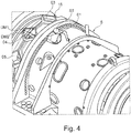
- FIG. 4 is a simplified perspective view on a part of the drive train 1 shown in FIG. 1 and FIG. 3 according to an embodiment.
- the service technician is located in the opening O1 in the main bearing housing 5.
- the openings O3, O4, O5 can have a rather circular or rectangular shape. In the present embodiment the openings have a rather rectangular shape.
- the maximum diameters DM1 and DM2 can then have the following advantageous dimensions.
- DM1 can be 400 mm to 600 mm, advantageously about 450 mm.
- the diameter DM2 can also be 400 mm to 600 mm, advantageously about 500 mm.
- Any opening in any of the housings may have a minimum diameter of 400 mm, more advantageously, the diameter of any opening should at least be 500 mm.
- the minimum diameter of any such opening can be greater than 600 mm.
- FIG. 5 is a simplified detailed view of an access opening O4 to an elastic element EM of the elastic coupling. Also in this situation, there are coinciding openings in the coupling housing 15 and in the coupling parts of the elastic coupling 10. The elastic element EM is partly lifted already towards the opening O4 in order to be replaced or checked. Likewise, it is possible to insert an elastic element EM through the opening 04.
- FIG. 6 is a simplified cross-sectional view of a part of the drive train 1 shown in FIG. 1 according to an embodiment.
- the opening O2 in the first coupling part 11 and an opening in the main bearing housing are such that the service technician ST can access the main bearing 4.
- This aspect is advantageous for maintaining or replacing, for example a sealing of the main bearing 4.
- FIG. 7 is a simplified cross-sectional view of an elastic coupling 10 along line A-A in FIG. 1 according to the embodiment shown in FIG. 1 and FIG. 2 .
- the elastic elements EM1 to EM10 are substantially evenly distributed along a circumferential direction CD.
- the elastic elements EM1 to EM10 are arranged in pairs of two elastic elements: EM1 and EM2, EM3 and EM4, EM5 and EM6, EM7 and EM8 as well as EM9 and EM10. Accordingly there a five pairs of elastic elements.
- Circumferential sections CS1, CS3, CS5, CS7 and CS9 belong to the first coupling part 11.
- Circumferential sections CS2, CS4, CS6, CS8 and CS10 belong to the second coupling part 12. Accordingly, each elastic element E1 to E10 is located between a circumferential section of the first coupling part 11 and a circumferential section of the second coupling part 12.
- the circumferential sections CS1 to CS10 provide attachment surfaces AS for the elastic elements EM1 to EM10 on opposite ends of the each elastic element EM1 to EM10.
- the circumferential direction CD is also the direction of the torque load.
- the torque load can have a first direction LDP or a second direction LDN which are opposite to each other.
- a torque or load torque or load torque direction is represented and described rather by the rotational direction than by the vector representation, as the referral to the rotational directions is considered more intuitive.
- FIG. 8 is a simplified cross-sectional view of an elastic coupling 10 along line A-A in FIG. 1 in a first load condition according to an embodiment.
- This embodiment of an elastic coupling 10 differs from the previous one in that each of the elastic elements EM1 to EM4 is configured and arranged such that the elastic elements EM1 to EM4 can be loaded in positive torque direction LDP as well as in the negative torque direction LDN.
- the first coupling part 11 and the second coupling part 12 are represented as disks having superposed windows W through which each of the elastic elements EM1 to EM4 protrudes.
- the first coupling part 11 is represented in dashed lines while the second coupling part 12 is represented by solid lines.
- the shown load condition is an undeflected situation such that no torque load is applied and the rotor shaft 3 and the gearbox input shaft 6 and therefore the coupling parts 11, 12 are not misaligned.
- FIG. 9 is a simplified cross-sectional view of the an elastic coupling 10 along line A-A in FIG. 1 (similar to the embodiment of FIG. 8 ) in a second load condition. In this load condition, load torque is applied to the elastic coupling 10 but the axes of the gearbox input shaft and the rotor shaft are still well aligned.
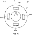
- FIG. 10 is a simplified cross-sectional view of the an elastic coupling 10 along line A-A in FIG. 1 (similar to the embodiment of FIG. 8 and FIG. 9 ) in a third load condition.
- load torque is applied and the main axes are misaligned.
- FIG. 11 is substantially similar to FIG. 8 including an additional detail.
- This embodiment uses elastic elements EM1 to EM4 which are also referred to as hydraulic rubber elements or hydraulic elastomers etc (more details of such an element are described with respect to FIG. 15 ). These elements have a inner chamber that can be filled with a fluid in order to adjust the stiffness (for example torsional stiffness).
- the elastic elements or rather the chambers of the elastic elements are coupled to a hydraulic circuit. If only a single elastic element EM1 to EM4 can be used for both load torque directions, as described herein, a single hydraulic circuit HYD can be used for all elements EM1 to EM4 instead of two separate hydraulic circuits for the elastic elements of each load torque direction.
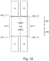
- FIG. 12 is a simplified cross-sectional view of a part of the embodiments shown in FIGs 8 to 10 using a single elastic element EM for two opposite torque load directions.
- Each of the elastic elements can be the elastic element EM shown in FIG. 11 .
- the first coupling part 11 provides at least a first attachment (or abutment) surface AS1_11 and an opposite second attachment (or abutment) surface AS2_11.
- the second coupling part 12 also provides at least a first attachment (or abutment) surface AS1_12 and an opposite second attachment (or abutment) surface AS2_12.
- one attachment (or abutment) surface AS1_11, AS1_12 of each of the two coupling parts 11, 12 is in contact with a same first side EMFS of the elastic element and one attachment (or abutment) surface AS2_11, AS2_12 of each of the two coupling parts 11, 12 is in contact with a same second side EMSS of the elastic element.
- the second side EMSS of the elastic element EM is opposite to the first side EMFS of the elastic element.
- the abutments surfaces AS1_11, AS2_11, AS1_12, AS2_12 can be provided by superposed or coinciding windows W11, W12 in the coupling parts.
- each of the two opposite sides EMFS, EMSS of the elastic element should at least abut against an abutment or attachment or contact surface of both, the first and the second coupling part 11, 12.
- the elastic elements are located on congruent attachment/abutment surfaces of the first and the second coupling part such that a single elastic element is loaded in a positive torque direction as well as in a the negative torque direction.
- a single elastic element EM can be used for both, opposite load torque direction, i.e. the positive torque direction LDP and the negative torque direction LDN.
- the elastic element is than only compressed or squeezed along the dominant axis or direction of stiffness regardless of the load torque direction.
- the number of required elastic elements EM can then be reduced to half the number of embodiments using pairs of modules.
- all the elastic elements can be hydraulically coupled with each other. It is not necessary to separate the hydraulic connection into one system for positive load torque and one system for negative load torque.
- FIG. 13 is a simplified cross-sectional view of a part of the embodiments shown in FIGs 8 to 11 using a single elastic element EM for two opposite torque load directions according to another embodiment.
- the elastic element EM is only held between one abutment, attachment and/or pushing surface (or shoulder) AS11 of the first coupling part 11 at one end of the elastic element EM and one abutment, attachment and/or pushing surface (or shoulder) AS12 of the second coupling part 12 at another, opposite end of the elastic element EM.
- the respective abutment surface AS11 and A12 of each coupling part 11, 12 extends over and covers the respective other coupling part. This embodiment is advantageous if the elastic element EM does not need to be pre-stressed.
- FIG. 14 is a simplified perspective view on an elastic element EM to be used for the embodiments and aspects described herein.
- the dominant direction D1 is the direction of a force (due to torque) in which the elastic element EM has the greatest stiffness. It should be noted that the elastic element EM is supposed to be compressed or squeezed in the dominant direction D1. Just as examples other directions D2, D3 of potential forces are also indicated.
- the elastic element EM has a lower stiffness in the directions D2 and D3 and any other direction different than D1.
- any elastic element EM has a dominant axis of stiffness DA and a dominant direction of stiffness D1 lying in the dominant axis of stiffness DA.
- the dominant direction of stiffness D1 is advantageously a direction in which the elastic element EM is compressed.
- the stiffness of the elastic element EM is greater in the dominant direction of stiffness D1 than in any direction relative to the elastic element EM different from the dominant direction D1.
- FIG. 15 is a simplified perspective view on an elastic element EM that can be used in connection with the aspects and embodiments of the invention.
- the elastic elements can comprise or be made of rubber, polymer, elastic material or combinations of rubber and/or polymer and/or elastic material and/or stiff components.
- At least one or all of the elastic elements can be configured or be made in form of springs, helical springs, and/or coil springs.
- At least one or all of the elastic elements can have the form of pads, cylinders, or cubicles.
- the elastic element EM shown in Fig. 15 is generally made of an elastic material (like rubber or polymers etc.) and comprises an inner chamber CH (dashed lines) that can be filled with a fluid in order to adjust the stiffness.
- the elastic element EM can further comprise inlet and outlets for the fluid.
- the elastic element EM can also be referred to as rubber hydraulic element. It can have a pitch cycle diameter of 2300 mm, a weight of 38 kg and provide a high torsional stiffness in the dominant direction. It further provides a low axial and lateral stiffness, i.e. in directions other than the dominant direction.
- the elastic element can operate with a hydraulic pressure of max. 600 bar. It can be hydraulically coupled with other elastic elements of a similar type through hoses or tubes (hydraulic circuit). The working pressure of these tubes or hoses can be 1040 bar, while the minimum burst pressure could be 2600 bar.
- FIG. 16 shows a simplified side view of a part of the drive train 1 of a wind turbine according to an embodiment.
- the drive train comprises a rotor shaft (or main shaft) 3 which is held by the main bearing 4 (not shown) in the bearing housing 5. Only the bearing housing 5 is suspended from or carried by the main frame 16.
- the coupling housing 15 including the elastic coupling 10, the gearbox housing 8 including the gearbox input shaft 6 and the gearbox 7 as well as the generator 9 are only suspended from the bearing housing 5. They all extend freely over the main frame 16.
- the entire weight of the elastic coupling 10, the gearbox, and the generator 9 including all their housings and internal parts can introduce an eccentricity between the rotor shaft 3 and the gearbox input shaft 6.
- a longitudinal axis A3 of the rotor shaft 3 and a longitudinal axis A6 of the gearbox input shaft 6 are then mounted/assembled with a predetermined and preset eccentricity EXC with respect to each other in order to minimize the offset/eccentricity resulting from, for example weight and/or other loads and/or other effects.
- a predetermined and preset eccentricity EXC with respect to each other in order to minimize the offset/eccentricity resulting from, for example weight and/or other loads and/or other effects.
- the rotor shaft 3 and the gearbox input shaft 6 of a drive train 1 of a wind turbine are perfectly aligned and centered with respect to each other. Otherwise, any coupling and in particular an elastic coupling 10, more specifically the elastic elements EM of the elastic coupling 10, as described herein, can be constantly agitated/worked through during each rotation.
- the rotor shaft 3 and the gearbox input shaft 6 are arranged with respect to each with a slight eccentricity in order to compensate any other effects that introduce an opposite eccentricity. If for example the coupling housing 15, the gearbox housing 8 and the generator 9 are all freely suspended from the bearing housing 5, this can introduce a slight eccentricity between the rotor shaft 3 and the gearbox input shaft 6 which results in an eccentricity in the elastic coupling 10, in particular an eccentricity of the first coupling part 11 with respect to the second coupling part 12. This and any other eccentricity can then be compensated, for example by the suspension of the bearing housing 5, in particular the suspension of the main bearing 4 in the bearing housing 5.
- the bearing housing 5 may be coupled to the main frame 16 of the nacelle by an annular (ring-shaped) flange (not shown).
- This flange can be used to create the eccentricity between the rotor shaft 3 and the gearbox input shaft 6.
- the center point of the bearing may be shifted during mounting/assembly.
- An advantageous direction is a preset eccentricity in a vertical direction V. It is also possible to create the preset eccentricity in any other directions, as for example the horizontal direction H.
- the preset eccentricity is advantageously in the range of less than 1 mm.
- the preset eccentricity provides that the elastic elements EM are not or less agitated during each rotation.
- the weight of these components can introduce an eccentricity that is to be compensated by a predetermined and preset eccentricity in the opposite direction. Accordingly, an expected or determined eccentricity can be compensated by a slight preset and compensating (for example opposite) eccentricity introduced by a shift of the bearing housing 5.
- the preset eccentricity of the longitudinal main axes of the rotor shaft and the gearbox input shaft can be used to compensate and/or minimize any eccentricity or offset resulting from weight and/or loads and/or torque.
- the relevant torque could be the normal expected torque during operation of the wind turbine.
- the center point of the bearing housing may be slightly shifted.
- the center point of the bearing housing may be shifted vertically. This has an influence on the bending line such that in total, the undesired eccentricities are compensated by the preset eccentricity during mounting and/or assembling of the wind turbine/drive train.
- the aspects and embodiments of the invention are particularly synergetic, as the elastic coupling 10 requires maintenance of the elastic elements.
- the openings provide access to these elements.
- the openings may also grant access to hydraulic circuits, tubes or hoses of any hydraulic parts or sensors provided in the elastic coupling. All these parts can be accessed and maintained or exchanged.
- the term "coinciding" openings can be interpreted as precisely overlapping, lying one above another or being precisely superposed. This means that any opening can be made just large enough to allow the respective measure to be taken (technician to pass or elastic element to be accessed, retrieved from or inserted into the elastic coupling).
Landscapes
- Engineering & Computer Science (AREA)
- General Engineering & Computer Science (AREA)
- Mechanical Engineering (AREA)
- Life Sciences & Earth Sciences (AREA)
- Sustainable Development (AREA)
- Sustainable Energy (AREA)
- Chemical & Material Sciences (AREA)
- Combustion & Propulsion (AREA)
- Physics & Mathematics (AREA)
- Acoustics & Sound (AREA)
- Aviation & Aerospace Engineering (AREA)
- Wind Motors (AREA)
Claims (13)
- Antriebsstrang (1) für eine Windturbine, umfassend: eine Rotorwelle (3) (Hauptwelle), die ausgelegt ist, um durch den Rotor um eine Hauptachse angetrieben zu werden; eine Stützkonstruktion (16) mit einem Lagergehäuse (5), das das mindestens eine Lager (4) umgibt und die Rotorwelle zur Drehung um die Hauptachse abstützt, um dadurch andere Bewegungen der Rotorwelle zu beschränken; eine Getriebeeingangswelle (6)und ein Getriebegehäuse (8), um die Getriebeeingangswelle zur Drehung um die Hauptachse abzustützen und gleichzeitig andere Bewegungen der Getriebeeingangswelle zu beschränken; und eine elastische Kupplung (10), wobei die Getriebeeingangswelle durch die elastische Kupplung mit der Rotorwelle gekoppelt ist, wobei die elastische Kupplung ein erstes Kupplungsteil (11), das starr mit der Rotorwelle verbunden ist, ein zweites Kupplungsteil (12), das starr mit der Getriebeeingangswelle verbunden ist, sowie elastische Elemente (EM) umfasst, die zwischen dem ersten Kupplungsteil und dem zweiten Kupplungsteil positioniert sind, so dass dadurch eine einzelne Verbindungsstelle zwischen der Rotorwelle und der Getriebeeingangswelle entsteht, wobei das Kupplungsgehäuse (15) und/oder das Lagergehäuse eine Öffnung (O1, O2) für einen Zugang zu einem Innenraum des Kupplungsgehäuses und/oder des Lagergehäuses umfasst, wobei der Antriebsstrang dadurch gekennzeichnet ist, dass die Öffnung des Kupplungsgehäuses und/oder des Lagergehäuses ein Mannloch ist, das es einem Wartungstechniker (ST) ermöglicht, durch diese Öffnung den Innenraum der elastischen Kupplung zu erreichen.
- Antriebsstrang (1) nach Anspruch 1, wobei das erste Kupplungsteil (11) und/oder das zweite Kupplungsteil (12) eine Öffnung (O2) umfasst, die mit der Öffnung (O1) des Kupplungsgehäuses (15) und/oder des Hauptlagergehäuses (5) in einer vorbestimmten verriegelten Position der Rotorwelle (3) so zusammenfällt, dass ein Innenraum des ersten Kupplungsteils und/oder des zweiten Kupplungsteils zugänglich ist.
- Antriebsstrang (1) nach Anspruch 1 oder 2, wobei die Öffnung (O1, O2) im Lagergehäuse (5) und/oder im Kupplungsgehäuse (15) so konfiguriert ist, dass sie einen Zugang zu den elastischen Elementen (EM) der elastischen Kupplung (10) zu Montage-, Demontage- oder Wartungszwecken ermöglicht.
- Antriebsstrang (1) nach Anspruch 2 oder 3, wobei die zusammenfallenden Öffnungen (O1, O2) als ein Mannloch dimensioniert sind, um einem Wartungstechniker (ST) einen Zugang durch die Öffnungen zu ermöglichen.
- Antriebsstrang (1) nach einem der vorstehend aufgeführten Ansprüche, wobei die Öffnung (O1, O2) im Hauptlagergehäuse (5) und/oder im Kupplungsgehäuse (15) so konfiguriert ist, dass ein Zugang zu einer Abdichtung des Hauptlagers (4) zu Wartungszwecken möglich ist.
- Antriebsstrang (1) nach einem der vorstehend aufgeführten Ansprüche, wobei die elastischen Elemente (EM) so konfiguriert sind, dass die elastischen Elemente eine erste Steifigkeit in einer ersten Lastrichtung (D1) und eine zweite Steifigkeit in einer zweiten Lastrichtung (D2) aufweisen, wobei die erste Steifigkeit größer als die zweite Steifigkeit ist, und wobei die elastischen Elemente so angeordnet sind, dass eine Hauptlastdrehmomentrichtung mit der ersten Lastrichtung zusammenfällt.
- Antriebsstrang (1) nach einem der vorstehend aufgeführten Ansprüche, wobei die Rotorwelle (3) und die Getriebeeingangswelle (6) mit einer voreingestellten Exzentrizität ihrer Längshauptachsen montiert sind, so dass eine Längsachse der Rotorwelle und eine Längsachse der Getriebeeingangswelle initial exzentrisch zueinander montiert sind, um eine Exzentrizität oder ein Versetzen aus Gewichtsgründen und/oder aufgrund von Lasten und/oder Drehmoment während des Betriebs zu minimieren.
- Antriebsstrang (1) nach einem der vorstehend aufgeführten Ansprüche, wobei die elastischen Elemente (EM) in einem nichtbelasteten Zustand vorgespannt sind, um eine Steifigkeit, insbesondere eine Torsionssteifigkeit, zu erhöhen.
- Antriebsstrang (1) nach einem der vorstehend aufgeführten Ansprüche, wobei jedes der elastischen Elemente (EM) eine Kammer (CH) enthält, die konfiguriert ist, um mit einem Fluid befüllt zu werden, und wobei mindestens einige der Kammern hydraulisch miteinander verbunden sind.
- Windturbine, die einen Antriebsstrang (1) nach einem der vorstehend aufgeführten Ansprüche umfasst.
- Windpark, der eine Windturbine nach Anspruch 10 umfasst.
- Verfahren zum Herstellen oder Nachrüsten einer Windturbine nach Anspruch 10.
- Verfahren für einen Zugang zu einer elastischen Kupplung (10) eines Antriebsstrangs (1) einer Windturbine, wobei das Verfahren die folgenden Schritte umfasst: Verriegeln einer Rotorwelle (3) des Antriebsstrangs in einer vorbestimmten Position, Zugang zur elastischen Kupplung durch Öffnungen (O1, O2), die in einer vorbestimmten Position zusammenfallen, wobei das Verfahren dadurch gekennzeichnet ist, dass die zusammenfallenden Öffnungen Mannlöcher sind, die einem Wartungstechniker (ST) einen Zugang durch diese Öffnungen ermöglichen, um einen Innenraum der elastischen Kupplung zu erreichen.
Priority Applications (7)
| Application Number | Priority Date | Filing Date | Title |
|---|---|---|---|
| DK15194639.9T DK3168461T3 (da) | 2015-11-15 | 2015-11-15 | Drivenhed til en vindmølle med elastisk kobling og vedligeholdelsesfremgangsmåde dertil |
| EP15194639.9A EP3168461B1 (de) | 2015-11-15 | 2015-11-15 | Windturbinenantriebsstrang mit elastischer kupplung und wartungsmethode dafür |
| ES15194639T ES2735075T3 (es) | 2015-11-15 | 2015-11-15 | Tren de transmisión para una turbina eólica con acoplamiento elástico y método de mantenimiento para el mismo |
| US15/775,926 US10550827B2 (en) | 2015-11-15 | 2016-11-15 | Methods and devices for accessing a drive train of a wind turbine with elastic coupling, wind turbine and methods |
| CN201680078953.7A CN108463632B (zh) | 2015-11-15 | 2016-11-15 | 用于进入具有弹性联轴器的风力涡轮机的驱动机构的方法和装置、风力涡轮机和方法 |
| EP16795104.5A EP3374630A1 (de) | 2015-11-15 | 2016-11-15 | Verfahren und vorrichtungen zum zugriff auf einen antriebsablauf einer windturbine mit elastischer kupplung, windturbine und verfahren |
| PCT/EP2016/077732 WO2017081333A1 (en) | 2015-11-15 | 2016-11-15 | Methods and devices for accessing a drive drain of a wind turbine with elastic coupling, wind turbine and methods |
Applications Claiming Priority (1)
| Application Number | Priority Date | Filing Date | Title |
|---|---|---|---|
| EP15194639.9A EP3168461B1 (de) | 2015-11-15 | 2015-11-15 | Windturbinenantriebsstrang mit elastischer kupplung und wartungsmethode dafür |
Publications (2)
| Publication Number | Publication Date |
|---|---|
| EP3168461A1 EP3168461A1 (de) | 2017-05-17 |
| EP3168461B1 true EP3168461B1 (de) | 2019-04-10 |
Family
ID=54542131
Family Applications (2)
| Application Number | Title | Priority Date | Filing Date |
|---|---|---|---|
| EP15194639.9A Active EP3168461B1 (de) | 2015-11-15 | 2015-11-15 | Windturbinenantriebsstrang mit elastischer kupplung und wartungsmethode dafür |
| EP16795104.5A Withdrawn EP3374630A1 (de) | 2015-11-15 | 2016-11-15 | Verfahren und vorrichtungen zum zugriff auf einen antriebsablauf einer windturbine mit elastischer kupplung, windturbine und verfahren |
Family Applications After (1)
| Application Number | Title | Priority Date | Filing Date |
|---|---|---|---|
| EP16795104.5A Withdrawn EP3374630A1 (de) | 2015-11-15 | 2016-11-15 | Verfahren und vorrichtungen zum zugriff auf einen antriebsablauf einer windturbine mit elastischer kupplung, windturbine und verfahren |
Country Status (6)
| Country | Link |
|---|---|
| US (1) | US10550827B2 (de) |
| EP (2) | EP3168461B1 (de) |
| CN (1) | CN108463632B (de) |
| DK (1) | DK3168461T3 (de) |
| ES (1) | ES2735075T3 (de) |
| WO (1) | WO2017081333A1 (de) |
Families Citing this family (8)
| Publication number | Priority date | Publication date | Assignee | Title |
|---|---|---|---|---|
| EP3168464A1 (de) * | 2015-11-15 | 2017-05-17 | Adwen GmbH | Antriebsablauf und verfahren für eine windturbine mit elastischer kupplung |
| EP3168463B1 (de) * | 2015-11-15 | 2019-05-08 | Adwen GmbH | Verfahren und vorrichtung zur überwachung eines antriebs einer windturbine mit elastischer kupplung |
| CN108843520B (zh) * | 2018-06-04 | 2020-03-03 | 太原重型机械集团工程技术研发有限公司 | 风电机组主传动系统 |
| US10951095B2 (en) * | 2018-08-01 | 2021-03-16 | General Electric Company | Electric machine arc path protection |
| CN110529346A (zh) * | 2019-09-02 | 2019-12-03 | 东方电气集团东方电机有限公司 | 一种大mw级低速直驱风力发电机轴系结构 |
| CN110725922B (zh) * | 2019-09-11 | 2020-10-13 | 浙江运达风电股份有限公司 | 一种双馈风电机组双主轴承传动装置及装配方法 |
| EP3792489A1 (de) * | 2019-09-16 | 2021-03-17 | Siemens Gamesa Renewable Energy A/S | Lageranordnung für eine windturbine sowie windturbine |
| WO2023001348A1 (en) * | 2021-07-20 | 2023-01-26 | Vestas Wind Systems A/S | Powertrain assembly for a wind turbine |
Family Cites Families (17)
| Publication number | Priority date | Publication date | Assignee | Title |
|---|---|---|---|---|
| US1362048A (en) * | 1917-04-05 | 1920-12-14 | Westinghouse Electric & Mfg Co | Resilient driving connection |
| US5385018A (en) * | 1990-02-28 | 1995-01-31 | Unisia Jecs Corporation | Device for transmitting automotive engine driving torque for automatic power transmission with feature of absorption of torsional vibration |
| US6663526B2 (en) * | 2002-01-08 | 2003-12-16 | Ford Global Technologies, Llc | Transmission isolation assembly |
| CN1856644B (zh) * | 2003-09-26 | 2010-09-22 | 维斯塔斯风力系统有限公司 | 在风轮机的轮毂已安装后对风轮机进行维护的方法和设备 |
| DE102007037542B4 (de) * | 2007-08-09 | 2017-08-03 | Nordex Energy Gmbh | Windenergieanlagengetriebe mit einer Inspektionsöffnung |
| US8075442B2 (en) * | 2008-09-05 | 2011-12-13 | General Electric Company | System and assembly for power transmission and generation in a wind turbine |
| CN102822519A (zh) * | 2010-03-29 | 2012-12-12 | 阿尔斯通风力有限个人公司 | 风力涡轮机 |
| US8786124B2 (en) * | 2010-07-12 | 2014-07-22 | Alstom Wind, S.L.U. | Wind turbine |
| ES2708452T5 (es) | 2010-10-18 | 2022-03-14 | Vestas Wind Sys As | Sistema de transmisión de potencia de turbina eólica |
| DK2732157T3 (da) | 2011-07-14 | 2019-07-01 | Esm Energie Und Schwingungstechnik Mitsch Gmbh | Elastisk, hydraulisk eller pneumatisk trykakkumulatorleje og anvendelse deraf i vindenergianlæg |
| EP2784309B1 (de) * | 2013-03-28 | 2019-07-17 | GE Renewable Technologies Wind B.V. | Verfahren zur Reduzierung der Antriebsstrangschwingungen in einer Windturbine |
| CN105308343B (zh) * | 2013-09-26 | 2019-04-30 | Pt技术有限公司 | 用以减轻转矩反向的风力涡轮机联接件 |
| GB201320191D0 (en) | 2013-11-15 | 2014-01-01 | Ricardo Uk Ltd | Wind turbine |
| US20160029860A1 (en) * | 2014-07-29 | 2016-02-04 | William Pordy, MD | Toilet seat |
| DK3139033T3 (da) * | 2015-09-07 | 2019-05-20 | Siemens Gamesa Renewable Energy As | Vedligeholdelsesadgang til vingeleje af vindmølle |
| DK3396190T3 (da) * | 2015-12-23 | 2021-01-04 | Idom S A U | Stiv forbindelsesstangkobling mellem to aksler |
| US20180320661A1 (en) * | 2017-05-03 | 2018-11-08 | General Electric Company | Compact Multi-Disk Rotor Brake System for a Wind Turbine |
-
2015
- 2015-11-15 DK DK15194639.9T patent/DK3168461T3/da active
- 2015-11-15 EP EP15194639.9A patent/EP3168461B1/de active Active
- 2015-11-15 ES ES15194639T patent/ES2735075T3/es active Active
-
2016
- 2016-11-15 US US15/775,926 patent/US10550827B2/en active Active
- 2016-11-15 EP EP16795104.5A patent/EP3374630A1/de not_active Withdrawn
- 2016-11-15 CN CN201680078953.7A patent/CN108463632B/zh active Active
- 2016-11-15 WO PCT/EP2016/077732 patent/WO2017081333A1/en active Application Filing
Non-Patent Citations (1)
| Title |
|---|
| None * |
Also Published As
| Publication number | Publication date |
|---|---|
| CN108463632B (zh) | 2021-02-09 |
| ES2735075T3 (es) | 2019-12-16 |
| EP3374630A1 (de) | 2018-09-19 |
| CN108463632A (zh) | 2018-08-28 |
| WO2017081333A1 (en) | 2017-05-18 |
| DK3168461T3 (da) | 2019-05-13 |
| US10550827B2 (en) | 2020-02-04 |
| US20180328347A1 (en) | 2018-11-15 |
| EP3168461A1 (de) | 2017-05-17 |
Similar Documents
| Publication | Publication Date | Title |
|---|---|---|
| EP3168461B1 (de) | Windturbinenantriebsstrang mit elastischer kupplung und wartungsmethode dafür | |
| EP3168463B1 (de) | Verfahren und vorrichtung zur überwachung eines antriebs einer windturbine mit elastischer kupplung | |
| EP3374633B1 (de) | Antriebsablauf und verfahren für eine windturbine mit elastischer kupplung | |
| US8393994B2 (en) | Gearbox for a wind turbine, a method of converting wind energy and use of a gearbox | |
| EP3019275B1 (de) | Schwerlast-antriebsanordnung und mühle damit | |
| CN102207060A (zh) | 风力涡轮机的转向盘 | |
| EP2383468A1 (de) | System und Verfahren zum Verbinden von Windturbinewellen | |
| EP2935881B1 (de) | Flexible antriebswelle | |
| CN106122076B (zh) | 一种特殊球顶结构端面齿型挠性联轴器 | |
| US11560877B2 (en) | Shaft-to-shaft connector for a wind turbine | |
| EP4166805A1 (de) | Ausgleichskupplung | |
| WO2013012340A1 (en) | Hydraulic transmission integrated into the nacelle of a wind turbine | |
| CN102644674A (zh) | 一种联轴器装置 | |
| EP2901042B1 (de) | Leistungsgetriebesystem für eine windturbine | |
| CN115076247A (zh) | 一种风电高速轴联轴器 | |
| SU1537176A2 (ru) | Мотовило сельскохоз йственной машины |
Legal Events
| Date | Code | Title | Description |
|---|---|---|---|
| PUAI | Public reference made under article 153(3) epc to a published international application that has entered the european phase |
Free format text: ORIGINAL CODE: 0009012 |
|
| STAA | Information on the status of an ep patent application or granted ep patent |
Free format text: STATUS: THE APPLICATION HAS BEEN PUBLISHED |
|
| AK | Designated contracting states |
Kind code of ref document: A1 Designated state(s): AL AT BE BG CH CY CZ DE DK EE ES FI FR GB GR HR HU IE IS IT LI LT LU LV MC MK MT NL NO PL PT RO RS SE SI SK SM TR |
|
| AX | Request for extension of the european patent |
Extension state: BA ME |
|
| STAA | Information on the status of an ep patent application or granted ep patent |
Free format text: STATUS: REQUEST FOR EXAMINATION WAS MADE |
|
| 17P | Request for examination filed |
Effective date: 20171117 |
|
| RBV | Designated contracting states (corrected) |
Designated state(s): AL AT BE BG CH CY CZ DE DK EE ES FI FR GB GR HR HU IE IS IT LI LT LU LV MC MK MT NL NO PL PT RO RS SE SI SK SM TR |
|
| GRAP | Despatch of communication of intention to grant a patent |
Free format text: ORIGINAL CODE: EPIDOSNIGR1 |
|
| STAA | Information on the status of an ep patent application or granted ep patent |
Free format text: STATUS: GRANT OF PATENT IS INTENDED |
|
| INTG | Intention to grant announced |
Effective date: 20181129 |
|
| GRAS | Grant fee paid |
Free format text: ORIGINAL CODE: EPIDOSNIGR3 |
|
| GRAA | (expected) grant |
Free format text: ORIGINAL CODE: 0009210 |
|
| STAA | Information on the status of an ep patent application or granted ep patent |
Free format text: STATUS: THE PATENT HAS BEEN GRANTED |
|
| AK | Designated contracting states |
Kind code of ref document: B1 Designated state(s): AL AT BE BG CH CY CZ DE DK EE ES FI FR GB GR HR HU IE IS IT LI LT LU LV MC MK MT NL NO PL PT RO RS SE SI SK SM TR |
|
| REG | Reference to a national code |
Ref country code: GB Ref legal event code: FG4D |
|
| REG | Reference to a national code |
Ref country code: CH Ref legal event code: EP Ref country code: AT Ref legal event code: REF Ref document number: 1119012 Country of ref document: AT Kind code of ref document: T Effective date: 20190415 |
|
| REG | Reference to a national code |
Ref country code: IE Ref legal event code: FG4D |
|
| REG | Reference to a national code |
Ref country code: DE Ref legal event code: R096 Ref document number: 602015027927 Country of ref document: DE |
|
| REG | Reference to a national code |
Ref country code: DK Ref legal event code: T3 Effective date: 20190510 |
|
| REG | Reference to a national code |
Ref country code: NL Ref legal event code: MP Effective date: 20190410 |
|
| REG | Reference to a national code |
Ref country code: LT Ref legal event code: MG4D |
|
| REG | Reference to a national code |
Ref country code: AT Ref legal event code: MK05 Ref document number: 1119012 Country of ref document: AT Kind code of ref document: T Effective date: 20190410 |
|
| PG25 | Lapsed in a contracting state [announced via postgrant information from national office to epo] |
Ref country code: NL Free format text: LAPSE BECAUSE OF FAILURE TO SUBMIT A TRANSLATION OF THE DESCRIPTION OR TO PAY THE FEE WITHIN THE PRESCRIBED TIME-LIMIT Effective date: 20190410 |
|
| PG25 | Lapsed in a contracting state [announced via postgrant information from national office to epo] |
Ref country code: FI Free format text: LAPSE BECAUSE OF FAILURE TO SUBMIT A TRANSLATION OF THE DESCRIPTION OR TO PAY THE FEE WITHIN THE PRESCRIBED TIME-LIMIT Effective date: 20190410 Ref country code: NO Free format text: LAPSE BECAUSE OF FAILURE TO SUBMIT A TRANSLATION OF THE DESCRIPTION OR TO PAY THE FEE WITHIN THE PRESCRIBED TIME-LIMIT Effective date: 20190710 Ref country code: AL Free format text: LAPSE BECAUSE OF FAILURE TO SUBMIT A TRANSLATION OF THE DESCRIPTION OR TO PAY THE FEE WITHIN THE PRESCRIBED TIME-LIMIT Effective date: 20190410 Ref country code: HR Free format text: LAPSE BECAUSE OF FAILURE TO SUBMIT A TRANSLATION OF THE DESCRIPTION OR TO PAY THE FEE WITHIN THE PRESCRIBED TIME-LIMIT Effective date: 20190410 Ref country code: SE Free format text: LAPSE BECAUSE OF FAILURE TO SUBMIT A TRANSLATION OF THE DESCRIPTION OR TO PAY THE FEE WITHIN THE PRESCRIBED TIME-LIMIT Effective date: 20190410 Ref country code: PT Free format text: LAPSE BECAUSE OF FAILURE TO SUBMIT A TRANSLATION OF THE DESCRIPTION OR TO PAY THE FEE WITHIN THE PRESCRIBED TIME-LIMIT Effective date: 20190910 Ref country code: LT Free format text: LAPSE BECAUSE OF FAILURE TO SUBMIT A TRANSLATION OF THE DESCRIPTION OR TO PAY THE FEE WITHIN THE PRESCRIBED TIME-LIMIT Effective date: 20190410 |
|
| PG25 | Lapsed in a contracting state [announced via postgrant information from national office to epo] |
Ref country code: RS Free format text: LAPSE BECAUSE OF FAILURE TO SUBMIT A TRANSLATION OF THE DESCRIPTION OR TO PAY THE FEE WITHIN THE PRESCRIBED TIME-LIMIT Effective date: 20190410 Ref country code: BG Free format text: LAPSE BECAUSE OF FAILURE TO SUBMIT A TRANSLATION OF THE DESCRIPTION OR TO PAY THE FEE WITHIN THE PRESCRIBED TIME-LIMIT Effective date: 20190710 Ref country code: PL Free format text: LAPSE BECAUSE OF FAILURE TO SUBMIT A TRANSLATION OF THE DESCRIPTION OR TO PAY THE FEE WITHIN THE PRESCRIBED TIME-LIMIT Effective date: 20190410 Ref country code: LV Free format text: LAPSE BECAUSE OF FAILURE TO SUBMIT A TRANSLATION OF THE DESCRIPTION OR TO PAY THE FEE WITHIN THE PRESCRIBED TIME-LIMIT Effective date: 20190410 Ref country code: GR Free format text: LAPSE BECAUSE OF FAILURE TO SUBMIT A TRANSLATION OF THE DESCRIPTION OR TO PAY THE FEE WITHIN THE PRESCRIBED TIME-LIMIT Effective date: 20190711 |
|
| REG | Reference to a national code |
Ref country code: ES Ref legal event code: FG2A Ref document number: 2735075 Country of ref document: ES Kind code of ref document: T3 Effective date: 20191216 |
|
| PG25 | Lapsed in a contracting state [announced via postgrant information from national office to epo] |
Ref country code: IS Free format text: LAPSE BECAUSE OF FAILURE TO SUBMIT A TRANSLATION OF THE DESCRIPTION OR TO PAY THE FEE WITHIN THE PRESCRIBED TIME-LIMIT Effective date: 20190810 Ref country code: AT Free format text: LAPSE BECAUSE OF FAILURE TO SUBMIT A TRANSLATION OF THE DESCRIPTION OR TO PAY THE FEE WITHIN THE PRESCRIBED TIME-LIMIT Effective date: 20190410 |
|
| REG | Reference to a national code |
Ref country code: DE Ref legal event code: R097 Ref document number: 602015027927 Country of ref document: DE |
|
| PG25 | Lapsed in a contracting state [announced via postgrant information from national office to epo] |
Ref country code: RO Free format text: LAPSE BECAUSE OF FAILURE TO SUBMIT A TRANSLATION OF THE DESCRIPTION OR TO PAY THE FEE WITHIN THE PRESCRIBED TIME-LIMIT Effective date: 20190410 Ref country code: CZ Free format text: LAPSE BECAUSE OF FAILURE TO SUBMIT A TRANSLATION OF THE DESCRIPTION OR TO PAY THE FEE WITHIN THE PRESCRIBED TIME-LIMIT Effective date: 20190410 Ref country code: EE Free format text: LAPSE BECAUSE OF FAILURE TO SUBMIT A TRANSLATION OF THE DESCRIPTION OR TO PAY THE FEE WITHIN THE PRESCRIBED TIME-LIMIT Effective date: 20190410 Ref country code: SK Free format text: LAPSE BECAUSE OF FAILURE TO SUBMIT A TRANSLATION OF THE DESCRIPTION OR TO PAY THE FEE WITHIN THE PRESCRIBED TIME-LIMIT Effective date: 20190410 |
|
| PLBE | No opposition filed within time limit |
Free format text: ORIGINAL CODE: 0009261 |
|
| STAA | Information on the status of an ep patent application or granted ep patent |
Free format text: STATUS: NO OPPOSITION FILED WITHIN TIME LIMIT |
|
| PG25 | Lapsed in a contracting state [announced via postgrant information from national office to epo] |
Ref country code: IT Free format text: LAPSE BECAUSE OF FAILURE TO SUBMIT A TRANSLATION OF THE DESCRIPTION OR TO PAY THE FEE WITHIN THE PRESCRIBED TIME-LIMIT Effective date: 20190410 Ref country code: SM Free format text: LAPSE BECAUSE OF FAILURE TO SUBMIT A TRANSLATION OF THE DESCRIPTION OR TO PAY THE FEE WITHIN THE PRESCRIBED TIME-LIMIT Effective date: 20190410 |
|
| 26N | No opposition filed |
Effective date: 20200113 |
|
| PG25 | Lapsed in a contracting state [announced via postgrant information from national office to epo] |
Ref country code: TR Free format text: LAPSE BECAUSE OF FAILURE TO SUBMIT A TRANSLATION OF THE DESCRIPTION OR TO PAY THE FEE WITHIN THE PRESCRIBED TIME-LIMIT Effective date: 20190410 |
|
| PG25 | Lapsed in a contracting state [announced via postgrant information from national office to epo] |
Ref country code: SI Free format text: LAPSE BECAUSE OF FAILURE TO SUBMIT A TRANSLATION OF THE DESCRIPTION OR TO PAY THE FEE WITHIN THE PRESCRIBED TIME-LIMIT Effective date: 20190410 |
|
| REG | Reference to a national code |
Ref country code: CH Ref legal event code: PL |
|
| PG25 | Lapsed in a contracting state [announced via postgrant information from national office to epo] |
Ref country code: CH Free format text: LAPSE BECAUSE OF NON-PAYMENT OF DUE FEES Effective date: 20191130 Ref country code: LU Free format text: LAPSE BECAUSE OF NON-PAYMENT OF DUE FEES Effective date: 20191115 Ref country code: LI Free format text: LAPSE BECAUSE OF NON-PAYMENT OF DUE FEES Effective date: 20191130 Ref country code: MC Free format text: LAPSE BECAUSE OF FAILURE TO SUBMIT A TRANSLATION OF THE DESCRIPTION OR TO PAY THE FEE WITHIN THE PRESCRIBED TIME-LIMIT Effective date: 20190410 |
|
| REG | Reference to a national code |
Ref country code: BE Ref legal event code: MM Effective date: 20191130 |
|
| PG25 | Lapsed in a contracting state [announced via postgrant information from national office to epo] |
Ref country code: IE Free format text: LAPSE BECAUSE OF NON-PAYMENT OF DUE FEES Effective date: 20191115 |
|
| PG25 | Lapsed in a contracting state [announced via postgrant information from national office to epo] |
Ref country code: BE Free format text: LAPSE BECAUSE OF NON-PAYMENT OF DUE FEES Effective date: 20191130 |
|
| PG25 | Lapsed in a contracting state [announced via postgrant information from national office to epo] |
Ref country code: CY Free format text: LAPSE BECAUSE OF FAILURE TO SUBMIT A TRANSLATION OF THE DESCRIPTION OR TO PAY THE FEE WITHIN THE PRESCRIBED TIME-LIMIT Effective date: 20190410 |
|
| PG25 | Lapsed in a contracting state [announced via postgrant information from national office to epo] |
Ref country code: MT Free format text: LAPSE BECAUSE OF FAILURE TO SUBMIT A TRANSLATION OF THE DESCRIPTION OR TO PAY THE FEE WITHIN THE PRESCRIBED TIME-LIMIT Effective date: 20190410 Ref country code: HU Free format text: LAPSE BECAUSE OF FAILURE TO SUBMIT A TRANSLATION OF THE DESCRIPTION OR TO PAY THE FEE WITHIN THE PRESCRIBED TIME-LIMIT; INVALID AB INITIO Effective date: 20151115 |
|
| REG | Reference to a national code |
Ref country code: DE Ref legal event code: R081 Ref document number: 602015027927 Country of ref document: DE Owner name: SIEMENS GAMESA RENEWABLE ENERGY DEUTSCHLAND GM, DE Free format text: FORMER OWNER: ADWEN GMBH, 27572 BREMERHAVEN, DE |
|
| PG25 | Lapsed in a contracting state [announced via postgrant information from national office to epo] |
Ref country code: MK Free format text: LAPSE BECAUSE OF FAILURE TO SUBMIT A TRANSLATION OF THE DESCRIPTION OR TO PAY THE FEE WITHIN THE PRESCRIBED TIME-LIMIT Effective date: 20190410 |
|
| REG | Reference to a national code |
Ref country code: DE Ref legal event code: R082 Ref document number: 602015027927 Country of ref document: DE Representative=s name: SAUTHOFF, KARSTEN, DIPL.-ING. UNIV., DE |
|
| PGFP | Annual fee paid to national office [announced via postgrant information from national office to epo] |
Ref country code: GB Payment date: 20231123 Year of fee payment: 9 |
|
| PGFP | Annual fee paid to national office [announced via postgrant information from national office to epo] |
Ref country code: ES Payment date: 20231215 Year of fee payment: 9 |
|
| PGFP | Annual fee paid to national office [announced via postgrant information from national office to epo] |
Ref country code: FR Payment date: 20231124 Year of fee payment: 9 Ref country code: DK Payment date: 20231122 Year of fee payment: 9 Ref country code: DE Payment date: 20231120 Year of fee payment: 9 |