EP3168322A1 - Coating weight control apparatus and coating weight control method - Google Patents
Coating weight control apparatus and coating weight control method Download PDFInfo
- Publication number
- EP3168322A1 EP3168322A1 EP16195854.1A EP16195854A EP3168322A1 EP 3168322 A1 EP3168322 A1 EP 3168322A1 EP 16195854 A EP16195854 A EP 16195854A EP 3168322 A1 EP3168322 A1 EP 3168322A1
- Authority
- EP
- European Patent Office
- Prior art keywords
- coating weight
- strip
- nozzle
- coating
- unit
- Prior art date
- Legal status (The legal status is an assumption and is not a legal conclusion. Google has not performed a legal analysis and makes no representation as to the accuracy of the status listed.)
- Granted
Links
- 238000000576 coating method Methods 0.000 title claims abstract description 387
- 239000011248 coating agent Substances 0.000 title claims abstract description 386
- 238000004260 weight control Methods 0.000 title claims abstract description 23
- 238000000034 method Methods 0.000 title claims description 109
- 229910000831 Steel Inorganic materials 0.000 claims abstract description 79
- 239000010959 steel Substances 0.000 claims abstract description 79
- 238000003860 storage Methods 0.000 claims description 40
- 238000012545 processing Methods 0.000 claims description 5
- 230000008676 import Effects 0.000 claims description 4
- 238000005507 spraying Methods 0.000 claims description 4
- 238000003466 welding Methods 0.000 abstract description 102
- 230000008569 process Effects 0.000 description 71
- 230000008859 change Effects 0.000 description 14
- 238000010586 diagram Methods 0.000 description 14
- 229920006395 saturated elastomer Polymers 0.000 description 7
- 238000001514 detection method Methods 0.000 description 4
- 230000006870 function Effects 0.000 description 4
- 230000003247 decreasing effect Effects 0.000 description 3
- 230000000694 effects Effects 0.000 description 3
- 238000004519 manufacturing process Methods 0.000 description 3
- 230000004048 modification Effects 0.000 description 3
- 238000012986 modification Methods 0.000 description 3
- 238000012937 correction Methods 0.000 description 2
- 238000005520 cutting process Methods 0.000 description 1
- 230000002349 favourable effect Effects 0.000 description 1
- 239000007787 solid Substances 0.000 description 1
- 238000006467 substitution reaction Methods 0.000 description 1
Images


Classifications
-
- C—CHEMISTRY; METALLURGY
- C25—ELECTROLYTIC OR ELECTROPHORETIC PROCESSES; APPARATUS THEREFOR
- C25D—PROCESSES FOR THE ELECTROLYTIC OR ELECTROPHORETIC PRODUCTION OF COATINGS; ELECTROFORMING; APPARATUS THEREFOR
- C25D7/00—Electroplating characterised by the article coated
- C25D7/06—Wires; Strips; Foils
- C25D7/0614—Strips or foils
- C25D7/0692—Regulating the thickness of the coating
-
- C—CHEMISTRY; METALLURGY
- C23—COATING METALLIC MATERIAL; COATING MATERIAL WITH METALLIC MATERIAL; CHEMICAL SURFACE TREATMENT; DIFFUSION TREATMENT OF METALLIC MATERIAL; COATING BY VACUUM EVAPORATION, BY SPUTTERING, BY ION IMPLANTATION OR BY CHEMICAL VAPOUR DEPOSITION, IN GENERAL; INHIBITING CORROSION OF METALLIC MATERIAL OR INCRUSTATION IN GENERAL
- C23C—COATING METALLIC MATERIAL; COATING MATERIAL WITH METALLIC MATERIAL; SURFACE TREATMENT OF METALLIC MATERIAL BY DIFFUSION INTO THE SURFACE, BY CHEMICAL CONVERSION OR SUBSTITUTION; COATING BY VACUUM EVAPORATION, BY SPUTTERING, BY ION IMPLANTATION OR BY CHEMICAL VAPOUR DEPOSITION, IN GENERAL
- C23C2/00—Hot-dipping or immersion processes for applying the coating material in the molten state without affecting the shape; Apparatus therefor
- C23C2/14—Removing excess of molten coatings; Controlling or regulating the coating thickness
- C23C2/16—Removing excess of molten coatings; Controlling or regulating the coating thickness using fluids under pressure, e.g. air knives
- C23C2/18—Removing excess of molten coatings from elongated material
- C23C2/20—Strips; Plates
-
- C—CHEMISTRY; METALLURGY
- C25—ELECTROLYTIC OR ELECTROPHORETIC PROCESSES; APPARATUS THEREFOR
- C25D—PROCESSES FOR THE ELECTROLYTIC OR ELECTROPHORETIC PRODUCTION OF COATINGS; ELECTROFORMING; APPARATUS THEREFOR
- C25D21/00—Processes for servicing or operating cells for electrolytic coating
- C25D21/12—Process control or regulation
Definitions
- the present invention relates to a technique of a coating weight control apparatus and a coating weight control method which control nozzles in a steel coating plant.
- a weight of a coating attached to a strip is determined by a strip speed (strip speed), which is the speed of the strip referred to as a line speed, a nozzle gap (nozzle-strip distance) which is a distance between a nozzle and the strip, a nozzle pressure (gas pressure) which is a pressure of gas discharged from the nozzle, and the like.
- strip speed which is the speed of the strip referred to as a line speed
- a nozzle gap nozzle-strip distance
- gas pressure gas pressure
- PTL 1 discloses a preset control method of a control system and a control apparatus using a control model in which "a first preset unit that calculates a control reference corresponding to a set value using a control model and sets the control reference as a preset value and a second preset unit that calculates a value of a control reference that needs to be changed in accordance with the amount of change of a control specification, and adds or subtracts the value to or from a current control reference, thereby obtaining a preset value are provided, a preset unit, which is capable of performing an appropriate control using manufacturing information or control information obtained from a plant by focusing on a control error and a model error is selected, and the control reference is changed.” (refer to the abstract).
- a nozzle may come into contact with the strip in the vicinity of the welding point.
- a so-called nozzle opening and closing control in which, before the welding point passes through the nozzle position, the nozzle is opened (nozzle gap is increased), and, after the welding point passes through the nozzle position, the nozzle is closed again to an appropriate position is performed. Therefore, near a welding point where the preset calculation in PTL 1 is performed, the nozzle is positioned not in a normal operating position, but in a position greatly distant from the strip.
- the coating weight prediction model is used for preset calculation.
- the coating weight prediction model is constructed using data at the time of a stable condition.
- the time of a stable condition means a time when a coating is performed in a condition in which the nozzle gap or the nozzle pressure does not change.
- a stable condition is a condition in which the coating weight acquired from the steel coating plant is a coating weight based on each of a current strip speed, a current nozzle pressure, and a current nozzle gap (each determined individually) imported from the steel coating plant.
- the coating weight has already been predicted when a nozzle gap which has become an abnormally large value is input.
- a second preset unit which performs the second preset control, performs adding and subtracting a control reference (nozzle pressure) corresponding to the change of amount of a control specification (target value of the coating weight) to or from a current control reference (nozzle pressure control reference). That is, based on the current control reference (nozzle pressure control reference), the control reference (nozzle pressure) at a next timing is calculated.
- the nozzle pressure in the next time is calculated.
- a greatly reduced nozzle pressure is calculated. That is, when the saturated pressure puts a limit, based on the current nozzle pressure which is greatly deteriorated further than an original nozzle pressure, the nozzle pressure in the next time is calculated, and thus there is a problem in that the nozzle pressure in the next time is greatly reduced to lower than that of a nozzle pressure needed to be calculated originally.
- the invention has been made in view of such a background, and the invention has an object of allowing nozzle control to be performed with high accuracy.
- the invention provides a coating weight control apparatus which receives result information from a steel coating plant, which attaches a coating having a desired coating weight to a strip by immersing a continuously sent strip into a bath of a molten coating and spraying high pressure gas from a nozzle so as to peel an unnecessary coating off immediately after the strip is lifted, generates control information for controlling a coating weight which is a coating weight of a coating based on the received result information, and transfers the generated control information to the steel coating plant
- the apparatus including a preset control unit that calculates at least the gas pressure as a set value for a control reference of the nozzle for attaching a coating having a desired coating weight, by calculation based on a coating weight prediction model indicating at least a relationship between a strip speed which is a moving speed of the strip, a gas pressure which is a pressure of the gas being sprayed from the nozzle, a nozzle-strip distance which is a distance between the nozzle and the strip, and the coating
- the preset control unit imports a first strip speed which is the current strip speed, a first nozzle-strip distance which is the current nozzle-strip distance, and a first target coating weight which is a target value of the current coating weight from the steel coating plant, calculates a first gas pressure of a set value which is the gas pressure for realizing the first target coating weight based on the coating weight prediction model, imports the second strip speed, the second nozzle-strip distance, and the second coating weight from the stable value storage unit, calculates a third gas pressure of a set value which is the gas pressure for realizing the coating weight corresponding to the second strip speed and the second nozzle-strip distance using the coating weight prediction model, adds the first gas pressure to the second gas pressure imported from the stable value storage unit, and calculates a fourth gas pressure which is a set value for a control reference of the nozzle by subtracting the third gas pressure.
- control of nozzles with high accuracy can be performed.
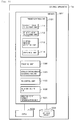
- Fig. 1 is a diagram illustrating a configuration example of a coating weight control system according to a first embodiment.
- the coating weight control system includes a control apparatus (coating weight control apparatus) 1, a steel coating plant 2, and a host computer (external device) 3.
- the control apparatus 1 controls the steel coating plant 2 which is a target to be controlled, and a coating having a desired coating weight is attached to a strip 401.
- the steel coating plant 2 is the target to be controlled of the control apparatus 1 as described above, and attaches a coating to the strip 401 based on a control reference of the control apparatus 1.
- the host computer 3 inputs information of a target coating weight, and the like to the control apparatus 1.
- the steel coating plant 2 immerses the strips 401, which are continuously sent, into a molten coating 202 accumulated in a pot 201. Accordingly, the strip 401 is plated. Also, the steel coating plant 2 peels an unnecessary coating off by spraying high pressure gas from a nozzle 211 immediately after the strip 401 is lifted from the molten coating 202. Accordingly, the steel coating plant 2 controls a coating weight of the coating attached to the strip 401 to be a desired value.
- the strips 401 (coil) are connected with each other in a welding manner, and have a configuration in which a continuous coating process is performed.
- a welding point 411 is coincide with, in general, a change point of a target coating weight.
- a plurality of coils are produced from one strip 401. That is, there is a case in which another coating is performed on one strip 401.
- a target value change point of the coating weight is present, and one strip 401 is controlled with another target coating weight.
- the coating weight W attached to the strip 401 is detected by a coating weight gauge 212.
- the coating weight gauge 212 is provided on a position apart away from a nozzle 211.
- the coating weight gauge 212 is traversed in a width direction of the strip 401, and an average value of the coating weight with respect to the width direction is output. Therefore, although a nozzle pressure (gas pressure) which is pressure of gas sprayed from the nozzle or a nozzle gap (nozzle-strip distance) which is a distance between the nozzle 211 and the strip 401 is operated, the coating weight can be detected as a result thereof after one or two minutes elapse. Accordingly, a preset control which predicts the coating weight and determines the nozzle pressure is a high importance target to be controlled.
- a roll 203 and a top roll 204 support the strip 401.
- the coating weight W is changed when receiving influence of various factors, but is mainly determined by a strip speed (strip speed) V of the strip 401 which is a moving speed of the strip 401, a nozzle pressure P, and a nozzle gap D. Also, the strip speed V of the strip 401 is calculated on the basis of a rotation speed, or the like of the roll 203 or the top roll 204.
- a0 to a3 are constants.
- nozzles 211 are respectively provided in a front side and a back side of the strip 401.
- an average value of both of them may be set to the nozzle pressure P.
- an average value of them may be set to the nozzle gap D.
- the coating weight W is also changed due to a temperature of the molten coating or the strip 401, a height of the nozzle 211, an angle with respect to the strip 401 of the nozzle 211, and the like.
- a regression model like Expression (1) the temperature of the molten coating or the strip 401, the height of the nozzle 211, the angle with respect to the strip 401 of the nozzle 211, and the like are not served as significance, and often omitted.
- the coating weight prediction model will be described as Expression (1).
- the strip 401 in which the coating weight is detected by the coating weight gauge 212, is cut by a cutting machine which is not illustrated finally, and is wound as a coil.
- the control apparatus 1 receives manufacturing information of the types of a steel, a thickness of a strip, a width of a strip, and the like of the strip 401 from the host computer 3 by adding the target coating weight W* corresponding to the strip 401 which will be processed next. There is a case in which an upper and lower limit value of the coating weight W or standard information of the strip 401 is included in the manufacturing information.
- the control apparatus 1 includes a preset control unit 101, a tracking unit (stable condition determination unit) 102, a stable coating weight determination unit (stable value storage processing unit) 103, a stable value storage unit (storage unit) 104, a feed back (FB) control unit 105, and an addition output unit 106.
- a preset control unit 101 a tracking unit (stable condition determination unit) 102, a stable coating weight determination unit (stable value storage processing unit) 103, a stable value storage unit (storage unit) 104, a feed back (FB) control unit 105, and an addition output unit 106.
- the preset control unit 101 uses a current target coating weight W*c acquired from the host computer 3, a current nozzle pressure Pc acquired from the steel coating plant 2, a current strip speed Vc, a current nozzle gap Dc, stable data of the stable value storage unit 104, and the like, and calculates a control reference (preset value Pref) of the nozzle pressure P.
- the stable data will be described later.
- the preset control unit 101 starts a process at the timing of receiving one of a change of the target coating weight W* from the host computer 3, a change of the nozzle gap D and a change of the strip speed V from the steel coating plant 2, and terminates the process when receiving a stable condition trigger from the stable coating weight determination unit 103.
- the tracking unit 102 traces a movement distance of the strip 401 by integrating the strip speed V acquired from the steel coating plant 2. In addition, the tracking unit 102 issues the stable condition trigger in a case of the stable condition.
- the stable condition refers to a condition in which a coating is attached by being corresponded to the nozzle pressure P, the nozzle gap D, and the strip speed V, and then the nozzle pressure P, the nozzle gap D, and the strip speed V are detected as the coating weight W by the coating weight gauge 212 while being not changed as they are.
- the stable condition is not recognized.
- the stable condition refers to a condition in which a result value of the current coating weight W acquired from the steel coating plant 2 is the coating weight W based on (each determined individually) the current strip speed V, the current nozzle pressure P, and the current nozzle gap D which are imported from the steel coating plant 2.
- the stable coating weight determination unit 103 acquires the current coating weight Wc, the nozzle pressure Pc, the nozzle gap Dc, and the strip speed Vc from the steel coating plant 2. In addition, when receiving the stable condition trigger from the tracking unit 102, the stable coating weight determination unit 103 stores the acquired current coating weight Wc, the nozzle pressure Pc, the nozzle gap Dc, and the strip speed Vc in the stable value storage unit 104 as the coating weight Ws, the nozzle pressure Ps, the nozzle gap Ds, and the strip speed Vs in the stable condition.
- the coating weight Ws, the nozzle pressure Ps, the nozzle gap Ds, and the strip speed Vs are respectively referred to as a stable coating weight Ws, a stable nozzle pressure Ps, a stable nozzle gap Ds, and a stable strip speed Vs. All of the stable coating weight Ws, the stable nozzle pressure Ps, the stable nozzle gap Ds, and the stable strip speed Vs are the result value.
- the stable coating weight Ws, the stable nozzle pressure Ps, the stable nozzle gap Ds, the stable strip speed Vs, and the like stored by the stable coating weight determination unit 103 are stored in the stable value storage unit 104.
- a FB control unit 105 When receiving the stable condition trigger from a stable condition coating weight determination unit 103, based on a deviation between the stable coating weight Ws acquired from the steel coating plant 2 and the current target coating weight W*c acquired from a host computer 3, a FB control unit 105 changes the nozzle pressure P in a direction in which the deviation is decreased.
- the addition output unit 106 outputs an output of the preset control unit 101 and an output of the FB control unit 105 by adding to each other.
- the preset control unit 101 performs a preset-control at the timing when the strip speed V and the nozzle gap D acquired from the target coating weight W* or the steel coating plant 2 are changed and switches the current nozzle pressure Pc to a nozzle pressure P realizing a desired coating weight.
- the target to be controlled is the nozzle pressure P
- the target to be controlled is not limited to the nozzle pressure P, and the nozzle gap D, and the like may be the target to be controlled.
- Fig. 2 is a diagram illustrating a hardware configuration of the control apparatus according to the first embodiment.
- the control apparatus 1 may be a personal computer (PC), and may be a programmable logic controller (PLC).
- PC personal computer
- PLC programmable logic controller
- the control apparatus 1 includes a memory 501 such as a random access memory (RAM), and a storage device 503 such as a central processing unit (CPU) 502, or a hard disc (HD).
- a memory 501 such as a random access memory (RAM)
- a storage device 503 such as a central processing unit (CPU) 502, or a hard disc (HD).
- the storage device 503 corresponds to the stable value storage unit 104 of Fig. 1 .
- the preset control unit 101 the tracking unit 102, the stable coating weight determination unit 103, the FB control unit 105, and the addition output unit 106 are implemented, when a program stored in the storage device 503 is load and the loaded program is executed by the CPU 502.
- Fig. 3 is a flow chart illustrating a sequence of a process in the preset control unit according to the first embodiment.
- Fig. 1 is appropriately referred to.
- this process is a process which is performed when a nozzle opening and closing process is performed. Specifically, the process is a process which starts at the timing when the control apparatus 1 receives a change of the nozzle gap D, before and after the welding point 411 passes through the nozzle 211.
- a process illustrated in Fig. 3 is terminated when the change of the nozzle gap D is terminated. Also, a process by the FB control unit 105 is stopped during performing the process by the preset control unit 101.
- the preset control unit 101 acquires the current strip speed (first strip speed) Vc, the current nozzle gap (first nozzle-strip distance) Dc, and the current nozzle pressure Pc (S101) from the steel coating plant 2.
- the current nozzle pressure Pc is a setting value of the current nozzle pressure P.
- the preset control unit 101 may not acquire the current nozzle pressure Pc.
- the preset control unit 101 acquires the current target coating weight W*c from the host computer 3 (S102).
- the preset control unit 101 acquires the stable data from the stable value storage unit 104 (S103).
- the stable data is a combination of the stable strip speed (second strip speed) Vs, stable nozzle gap (second nozzle-strip distance) Ds, and the stable coating weight (information of coating weight) Ws.
- a determination method of the stable condition or a storage of the stable data to the stable value storage unit 104 will be described later.
- the preset control unit 101 calculates the preset value Pref which is a control reference of the nozzle pressure based on the acquired stable data (S104).
- Step S104 a calculating method of the preset value Pref in Step S104 will be described in detail.
- Expression (1) can be rewritten in Expression (2) as follows.
- the preset value Pref calculated by the preset control unit 101 is calculated by adding and subtracting deviations between the current target coating weight W*c, the current strip speed Vc, the current nozzle gap Dc, and the stable coating weight Ws, the stable strip speed Vs, and the stable nozzle gap Ds stored in the stable value storage unit 104 to and from the stable nozzle pressure (second gas pressure) Ps stored in the stable value storage unit 104 by Expression (4) as follows.
- Pref Ps + f ⁇ 1 W * c , Vc , Dc ⁇ f ⁇ 1 Ws Vs Ds
- a second term (f -1 (W*c, Vc, Dc)) in a right side of Expression (4) indicates a nozzle pressure (first gas pressure) corresponding to the current target coating weight (first coating weight) W*c, the current strip speed Vc, and the current nozzle gap Dc.
- a third term (f -1 (Ws, Vs, Ds)) on the right side in Expression (4) indicates a nozzle pressure (third gas pressure) corresponding to the stable coating weight (result value of coating weight) Ws, the stable strip speed Vs, the stable nozzle gap Ds stored in the stable value storage unit 104.
- the preset value Pref (fourth gas pressure) is determined by Expression (5) as follows by proceeding with the second term and the third term of Expression (4).
- Fig. 4 is a flow chart illustrating a sequence of a process in the tracking unit according to the first embodiment.
- Fig. 1 is appropriately referred to.
- the tracking unit 102 determines whether or not the coating weight of the strip 401 detected by the coating weight gauge 212 is the stable coating weight. In order to determine the stable coating weight, the tracking unit 102 defines a tracking distance L which is a movement distance of the strip 401. The tracking distance L is added in accordance with a movement of the strip 401, and is reset at the timing when the welding point 411 passes through the nozzle 211 and at the timing of changing any one of the nozzle pressure P, the nozzle gap D, and the strip speed V.
- a process of Fig. 4 is executed during operating the steel coating plant 2.
- the tracking unit 102 resets the tracking distance L as an initializing process (S201).
- the tracking unit 102 determines whether or not the welding point 411 passes through a position of the nozzle 211 (nozzle position) based on the tracking distance L (S211) .
- the tracking unit 102 is capable of easily determining whether or not the welding point 411 passes through the position of the nozzle 211 (nozzle position).
- Step S211 in a case in which it is determined that whether or not the welding point 411 does not pass through the nozzle position (S211 ⁇ N), the tracking unit 102 proceeds a process to Step S213.
- Step S211 in a case in which it is determined that the welding point 411 passes through the nozzle position (S211 ⁇ Y), the tracking unit 102 determines that new process of the strip 401 is started, resets the tracking distance L (S212), and proceeds the process to Step S213.
- Step S213 the tracking unit 102 acquires the current strip speed Vc from the steel coating plant 2.
- ⁇ t in Expression (6) is an acquisition period of the strip speed Vc.
- the tracking unit 102 compares the current strip speed Vc with a reference speed Vo, and determines whether or not the strip speed Vc is less than the reference speed Vo (S221).
- the reference speed Vo is a determination index of whether or not the steel coating plant 2 is operated. That is, when the strip speed Vc is smaller than the reference speed Vo, the tracking unit 102 determines that a line is stopped.
- Step S221 in a case in which the strip speed Vc is less than the reference speed Vo (S221 ⁇ Y), the tracking unit 102 determines that operating of the steel coating plant 2 is terminated, and terminates the process.
- the tracking unit 102 determines whether or not the tracking distance L is greater than a reference distance Ls (S222).
- the reference distance Ls is a distance corresponding to a distance where the stable condition is established, and is defined as a value obtained by adding a distance corresponding to detection delay of the coating weight gauge 212 to a distance between the nozzle 211 and the coating weight gauge 212. That is, the reference distance Ls is a distance for determining whether or not the welding point 411 reaches the coating weight gauge 212.
- Step S222 in a case in which the tracking distance L is equal to or less than the reference distance Ls (S222 ⁇ N), the tracking unit 102 proceeds the process to Step S224.
- Step S222 in a case in which the tracking distance L is greater than the reference distance Ls (S222 ⁇ Y), the tracking unit 102 determines that the stable condition is established, and issues the stable condition trigger to the stable coating weight determination unit 103 (S223).
- An establishment condition of the stable condition is same as described above.
- the tracking distance L is greater than the reference distance Ls because a part of the strip 401 right under the nozzle 211 shows that any one of the nozzle pressure, the nozzle gap, and the strip speed is not changed until the coating weight gauge 212 detects the coating weight. That is, when the tracking distance L is greater than the reference distance Ls, it means that the welding point 411 passes through the coating weight gauge 212.
- the tracking unit 102 determines them to be the coating weight in accordance with each of a current strip speed, a current gas pressure, and a current nozzle-strip distance which are imported from the steel coating plant.
- the tracking unit 102 determines whether or not the coating weight acquired from the steel coating plant 2 is the coating weight which is stably detected (whether or not the coating weight is in the stable condition) using a positional information of the strip 401 based on the tracking distance of the strip 401.
- Step S224 the tracking unit 102 determines whether or not at least one of the nozzle pressure P, the nozzle gap D, and the strip speed V is changed.
- Step S224 in a case in which at least one of the nozzle pressure P, the nozzle gap D, and the strip speed V is changed (S224 ⁇ Y), the tracking unit 102 returns the process to Step S212 after waiting for a predetermined time ( ⁇ t), and resets the tracking distance L. At this time, the tracking unit 102 performs a notification to the effect that the condition is not the stable condition to the preset control unit 101, and the preset control unit 101 which receives the notification may start the process illustrated in Fig. 3 .
- the tracking unit 102 In a case in which any one of the nozzle pressure P, the nozzle gap D, and the strip speed V is not changed (S224 ⁇ N), the tracking unit 102 returns the process to Step S211 after waiting for the predetermined time ( ⁇ t), and repeats a process after Step S211.
- Fig. 5 is a diagram schematically illustrating a stable condition established timing inside one strip.
- a previous strip 401a and a next strip 401b are connected to the welding point 411 by welding.
- an example in which four times stable conditions are established indicated by numerals 602a to 602d is illustrated.
- a distance between the welding point 411 and the numeral 602a is great, because between the welding point and the numeral, for example, the nozzle gap is changed and the tracking distance L is reset.
- a distance between the numeral 602b and the numeral 602c is great, because between these numerals, for example, the strip speed is changed at a timing of the numeral 601 and the tracking distance L is reset.
- Fig. 6 is a flow chart illustrating a process sequence in the stable coating weight determination unit according to the first embodiment.
- Fig. 1 is appropriately referred to.
- the stable coating weight determination unit 103 determines whether or not the obtained coating weight is a value of the stable condition according to an output of the tracking unit 102. Also, when the coating weight is the value of the stable condition, the stable coating weight determination unit 103 updates the stable data stored in the stable value storage unit 104 to be the value.
- the stable coating weight Ws indicates the coating weight W when the nozzle pressure P, the nozzle gap D, and the strip speed V are not changed while a detection part of the coating weight is moved from the nozzle 211 to the coating weight gauge 212.
- the stable coating weight Ws indicates the coating weight W at the time of a condition in which the result value W of the current coating weight acquired from the steel coating plant 2 becomes the coating weight W based on each of the current strip speed V, the current nozzle pressure P, and the current nozzle gap D acquired from the steel coating plant 2.
- the coating weight (stable coating weight Ws), the nozzle pressure (stable nozzle pressure Ps), the strip speed (table strip speed Vs), and the nozzle gap (stable nozzle gap Ds) at this time are stored in the stable value storage unit 104 as a set of data items (stable data).
- the stable coating weight determination unit 103 acquires the current coating weight Wc, the nozzle pressure Pc, the nozzle gap Dc, and the strip speed Vc from the steel coating plant 2 (S301).
- the stable coating weight determination unit 103 determines whether or not the tracking unit 102 issues the stable condition trigger (S302).
- Step S302 in a case in which the tracking unit 102 does not issue the stable condition trigger (S302 ⁇ N), the stable coating weight determination unit 103 terminates the process.
- Step S302 in a case in which the tracking unit 102 issues the stable condition trigger (S302 ⁇ Y), the stable coating weight determination unit 103 updates the stable data in which the coating weight Wc, the nozzle pressure Pc, the nozzle gap Dc, and the strip speed Vc acquired in Step S301 are respectively stored in the stable value storage unit 104 as the stable coating weight Ws, the stable nozzle pressure Ps, the stable nozzle gap Ds, the stable strip speed Vs (S303).
- the stable coating weight determination unit 103 performs feedback-controlling on the FB control unit 105 (S304).
- the FB control unit 105 calculates a correction amount ⁇ P of the nozzle pressure for closing the stable coating weight Ws to the target coating weight W*c, for example, by Expression (7) when comparing the stable coating weight Ws obtained in the stable condition with the current target coating weight W*c.
- ⁇ P ⁇ ⁇ ⁇ P / ⁇ W ⁇ W * c ⁇ Ws
- ⁇ is a constant corresponding to a control gain
- ( ⁇ P/ ⁇ W) is a constant corresponding to an influence coefficient
- the addition output unit 106 outputs a value obtained by adding the preset value Pref output by the preset control unit 101 and the correction amount ⁇ P of the nozzle pressure output by the FB control unit 105 with respect to the nozzle 211 as the control reference (preset value) of the nozzle pressure.
- the coating weight stored in the stable value storage unit 104 an example in which the result value of the coating weight detected by the coating weight gauge 212 is described, but the target coating weight acquired from the host computer 3 may be stored instead.
- the result value of the coating weight is controlled to be close to the target coating weight. Accordingly, at the timing of obtaining the stable coating weight, the coating weight and the target coating weight become a similar value. Accordingly, the target coating weight can be used instead of the result value of the coating weight.
- Expression (4) and Expression (5) are replaced by Expression (4a) and Expression (5a) as follows.
- the embodiment can be applied as it is by considering of 1/2 of the distance as the nozzle gap (nozzle-strip distance).
- Fig. 7 is a diagram illustrating an example of a nozzle control according to the first embodiment.
- a change of the nozzle gap and the nozzle pressure by the preset control unit 101 is schematically illustrated.
- Fig. 7 the previous strip 401a and the next strip 401b are connected to the welding point 411.
- An opening and closing operation of the nozzle gap (change of nozzle gap) is illustrated by a line 701 of an upper side of Fig. 7
- a change of the nozzle pressure output by the preset control unit 101 is illustrated by a line 702 of a lower side thereof.
- the nozzle pressure is increased by a nozzle pressure calculation of the preset control unit 101, and an influence of opening of the nozzle gap on the coating weight is offset.
- the numeral 611 indicates a timing where the stable condition is established in the previous strip 401a at the end, before the nozzle gap is changed.
- the preset control unit 101 acquires the current nozzle gap Dc, the strip speed Vc, and the like from the steel coating plant 2 at the timing of calculating the nozzle pressure P after the numeral 611 (refer to Step S101 of Fig. 3 ).
- the preset control unit 101 acquires a target value W*c of the current coating weight from the host computer 3 at the timing of calculating the nozzle pressure P after the numeral 611 (refer to Step S102 of Fig. 3 ).
- the preset control unit 101 acquires the stable nozzle gap Ds, the stable strip speed Vs, a stable coating weight Ws acquired at the timing of the numeral 611 (refer to Step S103 of Fig. 3 ), at the timing of calculating the nozzle pressure P after the numeral 611.
- the preset control unit 101 calculates the preset value Pref by Expression (5) at the timing of calculating the nozzle pressure P after the numeral 611 (refer to Step S104 of Fig. 3 ).
- the nozzle pressure P increases in a process of the nozzle gap D opening and is saturated at the upper limit value before the nozzle gap is fully opened.
- the welding point 411 passes through the nozzle position, and the nozzle pressure P is also decreased according to closing of the nozzle gap D.
- the nozzle pressure after the nozzle closing is terminated is also preset-calculated, in the same manner, until next stable condition is established, based on the stable nozzle pressure Ps, the stable nozzle gap Ds, the stable strip speed Vs, and the stable coating weight Ws stored in the stable value storage unit 104.
- the preset control unit 101 calculates a subsequent nozzle pressure, based on the nozzle pressure 711 at a timing 611 where the stable condition is established in the end in the previous strip 401a as a referent point, as described in the numeral 712.
- This condition is terminated when an opening and closing operation of the nozzle gap D is terminated.
- a subsequent nozzle pressure is calculated.
- the preset value of the calculated nozzle pressure does not affect a calculating result at an operating point where the nozzle gap is greatly opened. That is, even at the time where saturation outputting is terminated, since the nozzle pressure which becomes a reference point is the nozzle pressure 711 at the timing 611 as it is, the nozzle pressure can be stably controlled.
- the control apparatus 1 illustrated in the embodiment calculates a subsequent nozzle pressure, but it is not limited thereto. According to the nozzle pressure when the stable condition is established, it may not be the stable nozzle pressure 711 at the timing 611 where the stable condition is established in the end.
- the stable coating weight Ws, the target coating weight W*s at the time of the stable condition, the stable strip speed Vs, the stable nozzle gap Ds which are used in Expression (4), Expression (5), Expression (4a), and Expression (5a), are acquired at the timing where the stable nozzle pressure Ps used in each Expression is acquired.
- a control target is the nozzle pressure P
- a control target may be the nozzle gap D, and may be both of the nozzle pressure P and the nozzle gap D.
- the method of the embodiment can be applied to.
- the nozzle pressure is limited to be the saturated pressure, but if there is no need to limit, the nozzle pressure may not be limited to the saturated pressure.
- Fig. 8 is a diagram illustrating a configuration of a coating weight control system according to a second embodiment.
- a preset control unit 101a in a control apparatus 1a in Fig. 8 includes an absolute value calculating unit (first preset control unit) 111, a relative value calculating unit (second preset control unit) 112, a control method selecting unit (selecting unit) 113, and a switching unit 114.
- the absolute value calculating unit 111 presets the nozzle pressure by calculating an absolute value of the nozzle pressure using the coating weight prediction model.
- the absolute value of the nozzle pressure is a nozzle pressure which is calculated on the basis of only information at the current timing without referring to a nozzle pressure at a previous timing.
- the relative value calculating unit 112 calculates the nozzle pressure which is need to be changed with respect to the amount of change of the target coating weight, and performs a preset by performing adding and subtracting with respect to the current nozzle pressure. That is, a preset process which is performed by the relative value calculating unit 112 is the same process as that of the preset control unit 101 in the first embodiment.
- a preset control executed by the absolute value calculating unit 111 is referred to as an absolute value preset
- a preset control executed by the relative value calculating unit 112 is referred to as a relative value preset.
- the preset value of the nozzle pressure calculated by the absolute value calculating unit 111 is appropriately referred to as an absolute preset value
- the preset value of the nozzle pressure calculated by the relative value calculating unit 112 is appropriately referred to as a relative preset value.
- control method selecting unit 113 selects which one of the absolute preset value calculated by the absolute value calculating unit 111 and a relative preset value calculated by the relative value calculating unit 112 is actually used.
- the switching unit 114 switches an output of the preset control unit 101a to an output from the absolute value calculating unit 111 and an output from the relative value calculating unit 112 in accordance with the output of the control method selecting unit 113.
- control apparatus 1a illustrated in Fig. 8 includes the welding point vicinity determination unit 121.
- the welding point vicinity determination unit 121 determines whether or not the welding point 411 comes close to the nozzle position from the current strip speed Vc acquired from the steel coating plant 2, the timing when the welding point 411 passes through the nozzle position, and the like, and notifies a condition to the preset control unit 101a at the time of being close.
- the preset control unit 101a is started as long as at a timing when the welding point 411 is determined to be near the nozzle position by the welding point vicinity determination unit 121. That is, when the preset control unit 101a receives a vicinity trigger issued by the welding point vicinity determination unit 121 in Steps S503 and S533 of Fig. 11 to be described later, the preset control unit 101a starts the process. In addition, when the preset control unit 101a receives a vicinity release trigger issued by the welding point vicinity determination unit 121 in Step S523 of Fig. 11 to be described later, the preset control unit 101a terminates the process.
- Fig. 9 is a diagram illustrating a hardware configuration of a control apparatus according to the second embodiment.
- control apparatus 1a when a program stored in the storage device 503 is loaded by the memory 501, and executed by CPU 502, in addition to each unit 102, 103, 105, and 106 illustrated in Fig. 2 , the welding point vicinity determination unit 121 or, the absolute value calculating unit 111, the relative value calculating unit 112, the control method selecting unit 113, the switching unit 114, and the like executed by the preset control unit 101a are implemented.
- the process executed by the relative value calculating unit 112 is the same as the process executed by the preset control unit 101 of the first embodiment using Expression (4) and Expression (5), and thus descriptions of those will be omitted here.
- Fig. 10 is a flow chart illustrating a sequence of a process in the absolute value calculating unit according to the second embodiment.
- the absolute value calculating unit 111 acquires the current strip speed Vc and the current nozzle gap Dc from the steel coating plant 2, and acquires the current target coating weight W*c from the host computer 3 (S401). Also, the absolute value calculating unit 111 acquires, for example, the current strip speed Vc, the current nozzle gap Dc, and the target coating weight W*c for every constant time, and as illustrated in the first embodiment, it does not matter whether or not it is the stable condition.
- the absolute value calculating unit 111 calculates the preset value Pref (fifth gas pressure) of the nozzle pressure by Expression (8) as follows (S402).
- Pref f ⁇ 1 W * c , Vc , Dc
- the target coating weight W*c is expressed by Expression (9) as follows.
- Expression (8) can be rewritten in Expression (10) as follows by Expression (9).
- Pref exp ln W * c ⁇ a 0 ⁇ a 2 ⁇ ln Vc ⁇ a 3 ⁇ ln Dc / a 1
- Fig. 11 is a flow chart illustrating a process sequence in the welding point vicinity determination unit according to the second embodiment.
- the welding point vicinity determination unit 121 determines whether or not the current strip speed Vc is greater than the reference speed Vo (S501).
- the reference speed Vo is a determination index for determining whether or not the steel coating plant 2 is operated as described above, and when the strip speed Vc is greater than the reference speed Vo, it indicates that the steel coating plant 2 is performing the process of the strip 401.
- Step S501 in a case in which the current strip speed Vc is equal to or less than the reference speed Vo (S501 ⁇ N), the welding point vicinity determination unit 121 returns the process to Step S501.
- Step S501 in a case in which the current strip speed Vc is greater than the reference speed Vo (S501 ⁇ Y), the welding point vicinity determination unit 121 determines whether or not the welding point 411 passes through the nozzle position (S502). Determination whether or not the welding point 411 passes through the nozzle position is performed on the basis of the tracking distance L calculated by the tracking unit 102.
- Step S502 in a case in which the welding point 411 does not passes through the nozzle position (S502 ⁇ N), the welding point vicinity determination unit 121 returns the process to Step S501.
- Step S502 in a case in which the welding point 411 passes through the position of the nozzle 211 (S502 ⁇ Y), that is, according to a start of a process of new strip 401 (coil), the welding point vicinity determination unit 121 determines whether or not the nozzle position is near the welding point 411, issues the vicinity trigger (S503), and starts a process as follows.
- the welding point vicinity determination unit 121 determines whether or not the welding point 411 passes through the position of the nozzle 211 (S511).
- Step S511 in a case in which the welding point 411 does not pass through the position of the nozzle 211 (S511 ⁇ N), the welding point vicinity determination unit 121 proceeds the process to Step S513.
- Step S511 in a case in which the welding point 411 passes through the position of the nozzle 211 (S511 ⁇ Y), the welding point vicinity determination unit 121 resets the tracking distance L (S512), and proceeds the process to Step S513.
- Step S513 the welding point vicinity determination unit 121 acquires the strip speed Vc from the steel coating plant 2, and calculates the tracking distance L of the strip 401 by Expression (6) whenever the speed is acquired (S514).
- the welding point vicinity determination unit 121 determines whether or not the acquired strip speed Vc is greater than the reference speed Vo (S521).
- Step S521 in a case in which the strip speed Vc is equal to or less than the reference speed Vo (S521 ⁇ N), the welding point vicinity determination unit 121 determines that operating of the steel coating plant 2 is terminated, and terminates the process.
- Step S521 in a case in which the strip speed Vc is greater than the reference speed Vo (S521 ⁇ Y), the welding point vicinity determination unit 121 determines whether or not the tracking distance L is greater than a first reference distance Ld (S522).
- the first reference distance Ld is set in advance to a value which is sufficiently longer than a length between a timing when the nozzle opening and closing in the next strip 401 is terminated after the welding point 411 passes through, and the welding point 411.
- An example of the first reference distance Ld is illustrated in Fig. 13 .
- Step S522 the welding point vicinity determination unit 121 determines whether or not a part of the strip 401, which is a range of the first reference distance Ld in Fig. 13 , when passing through the nozzle 211, already passed through the coating weight gauge 212.
- Step S522 in a case in which the tracking distance L is equal to or less than the first reference distance Ld (S522 ⁇ N), after waiting for a predetermined time ( ⁇ t), the welding point vicinity determination unit 121 returns the process to Step S513.
- Step S522 in a case in which the tracking distance L is greater than the first reference distance Ld (S522 ⁇ Y), the welding point vicinity determination unit 121 determines whether or not it is not near the welding point 411, issues a vicinity release trigger (S523), and releases a welding point vicinity determination.
- the welding point vicinity determination unit 121 acquires the strip speed Vc from the steel coating plant 2 (S524), and calculates the tracking distance L of the strip 401 by Expression (6) whenever the speed is acquired (S525).
- the welding point vicinity determination unit 121 determines whether or not the acquired strip speed Vc is greater than the reference speed Vo (S531).
- Step S531 in a case in which the strip speed Vc is equal to or less than the reference speed Vo (S531 ⁇ N), the welding point vicinity determination unit 121 determines that operating of the steel coating plant 2 is terminated, and terminates the process.
- Step S531 in a case in which the strip speed Vc is greater than the reference speed Vo (S531 ⁇ Y), the welding point vicinity determination unit 121 determines whether or not a value (Lc-L) which is obtained by subtracting the tracking distance L from a coil length Lc is less than a second reference distance Le (S532).
- the second reference distance Le is set in advance to be a value which is sufficiently longer than a length between the timing when the nozzle opening and closing is started in the current strip 401 before passing through the welding point 411, and the welding point 411.
- the second reference distance Le is illustrated in Fig. 13 .
- the coil length Lc is a length from the welding point 411 to the welding point 411.
- Step S532 the welding point vicinity determination unit 121 determines whether or not a part of the strip 401, which is a range of the second reference distance Le in Fig. 13 at the time of passing through the nozzle 211, currently passes through the coating weight gauge 212.
- Step S532 in a case in which a value (Lc-L) which is obtained by subtracting the tracking distance L from the coil length Lc is equal to or more than Le (S532 ⁇ N), the welding point vicinity determination unit 121 returns the process to Step S524 after waiting for the predetermined time ( ⁇ t).
- the welding point vicinity determination unit 121 determines that it is near the welding point 411, issues the vicinity trigger (S533), and returns the process to Step S511.
- Fig. 12 is a flow chart illustrating a sequence of a process in the control method selecting unit according to the second embodiment.
- the process is started at the same time when the process of the preset control unit 101a is started. That is, when the preset control unit 101a receives the vicinity trigger issued by the welding point vicinity determination unit 121 in Step S503 and S533 of Fig. 11 , a process of Fig. 12 is started. In addition, when the preset control unit 101a receives a vicinity release trigger issued by the welding point vicinity determination unit 121 in Step S523 of Fig. 11 , the process of Fig. 12 is terminated.
- the control method selecting unit 113 selects which one of the absolute preset value and the relative preset value is used according to whether or not the welding point 411 passes through the position of the nozzle 211 in addition to a degree of similarity of a control specification of a control value, and the like in a coating control.
- a degree of similarity of a control specification of a control value and the like in a coating control.
- an example is described of which the degree of similarity of the control specification after the welding point 411 passes is reprehensive of the target value of the coating weight.
- the control method selecting unit 113 acquires the current target coating weight W*c from the host computer 3, and further acquires the result value W of the coating weight obtained in the last controlling from the coating weight gauge 212 in the steel coating plant 2 (S601). Also, since the result value W of the coating weight obtained in the last controlling is actually considered to be a result value of the current coating weight, it is set to be the coating weight Wc here.
- control method selecting unit 113 determines whether or not the welding point 411 passes through the position of the nozzle 211 (S602).
- the control method selecting unit 113 determines whether or not, the welding point vicinity determination unit 121 acquires a signal of resetting the tracking distance L, and the welding point 411 passes through the position of the nozzle 211 based on the signal in a process in Step S511 of Fig. 11 .
- Step S602 in a case in which the welding point 411 does not pass through the position of the nozzle 211 (S602 ⁇ N), the control method selecting unit 113 instructs the switching unit 114 to select the relative value calculating unit 112 (S605).
- Step S602 in a case in which the welding point 411 passes through the position of the nozzle 211 (S602 ⁇ Y), the control method selecting unit 113 determines whether or not an absolute value (deviation) of a difference between the target coating weight W*c and the coating weight Wc is greater than a certain value ⁇ Z (S603).
- Step S603 in a case in which an absolute value of a difference between the target coating weight W*c and the result coating weight Wc is equal to or less than the certain value ⁇ Z (S603 ⁇ N), the control method selecting unit 113 instructs the switching unit 114 to select the relative value calculating unit 112 (S605).
- Step S604 in a case in which the absolute value of the difference between the target coating weight W*c and the result coating weight Wc is greater than the certain value ⁇ Z (S603 ⁇ Y), the control method selecting unit 113 instructs the switching unit 114 to select the absolute value calculating unit 111 (S604).
- the switching unit 114 switches the output of the relative value calculating unit 112 and the output of the absolute value calculating unit 111, and outputs them according to the instruction of the control method selecting unit 113.
- the target coating weight as the index for the control method selecting unit 113 to select the output, but it is also possible to consider that the degree of similarity is calculated by adding the mutual difference or the like of the lower limit values of the coating weight in the previous strip 401a ( Fig. 13 ) and a next strip 402b ( Fig. 13 ).
- Fig. 13 is a diagram illustrating an example of the nozzle controlling according to the second embodiment.
- a vicinity range of the welding point 411 is defined to sufficiently include a range where the nozzle gap is opened and closed over the welding point 411.
- the opening and closing operation of the nozzle gap is illustrated by a line 801 of an upper side of Fig. 13
- nozzle pressure operation output by the preset control unit 101a is illustrated by a line 802 of a lower side of Fig. 13 .
- the nozzle pressure becomes greater by calculating the nozzle pressure of the preset control unit 101a, and an influence of opening of the nozzle gap on the coating weight is offset.
- the welding point 411 passes through the nozzle position, and the nozzle pressure is also decreased as the nozzle gap is closed.
- the numeral 611 indicates a timing when the stable condition is established in the end in the previous strip 401a.
- the relative value calculating unit 112 is selected in the preset control unit 101a. That is, in a time region 811 before the welding point 411 passes through the position of the nozzle 211, a process same as that of the first embodiment is performed.
- the preset control unit 101a calculates the nozzle pressure by an absolute preset using the absolute value calculating unit 111 when the difference is great, and by a relative value calculation using the stable data stored in the stable value storage unit 104 when the difference is small.
- time regions 811 and 812 are respectively near the welding point 411, and include time when the nozzle opening and closing are controlled.
- the welding point 411 passes through the nozzle position and the next strip 401b is processed, a similarity is compared.
- a difference between the current target coating weight W*c and the result coating weight Wc is applied as the similarity.
- the same process as that of the first embodiment is performed.
- the nozzle pressure control by the absolute preset value is performed.
- the tracking unit 102 and the welding point vicinity determination unit 121 in Fig. 8 may be combined into one.
- the invention is not limited to the embodiment described above, and various modification examples are included therein.
- the embodiment described above is described in detail in order to easily understand the invention, and the invention is not necessarily limited to apparatuses and methods including all of the described configurations.
- a part of a configuration of a certain embodiment can be replaced with a configuration of another embodiment, and the configuration of another embodiment can be also added to the configuration of a certain embodiment.
- addition, deleting, and substitutions of another configuration can be made to a part of a configuration of each embodiment.
- each configuration, function, units 101 to 103, 105, 106, 101a, 111 to 114, and 121, the stable value storage unit 104, and the like, some or all thereof may be implemented by, for example, hardware when being designed as an integrated circuit.
- each configuration, function, and the like described above may be implemented by software when a processor such as the CPU 502 interprets and executes a program realizing each function.
- Information of a program, table, file, and the like realizing each function can be stored in a recording device, such as a memory or a solid state drive (SSD), or a recording medium such as an integrated circuit (IC) card, a secure digital (SD) card, or a digital versatile disc (DVD), in addition to storing in a hard disk (HD).
- a recording device such as a memory or a solid state drive (SSD), or a recording medium such as an integrated circuit (IC) card, a secure digital (SD) card, or a digital versatile disc (DVD), in addition to storing in a hard disk (HD).
- SSD solid state drive
- IC integrated circuit
- SD secure digital
- DVD digital versatile disc
- control line or a information line that are considered to be necessary for description are indicated and products may not indicate all of the control lines or information lines. Actually, almost all of the configurations may be considered to be connected to each other.
Landscapes
- Chemical & Material Sciences (AREA)
- Engineering & Computer Science (AREA)
- Organic Chemistry (AREA)
- Chemical Kinetics & Catalysis (AREA)
- Materials Engineering (AREA)
- Metallurgy (AREA)
- Electrochemistry (AREA)
- Mechanical Engineering (AREA)
- Automation & Control Theory (AREA)
- Coating With Molten Metal (AREA)
- Feedback Control In General (AREA)
- Application Of Or Painting With Fluid Materials (AREA)
- Electroplating Methods And Accessories (AREA)
Abstract
Description
- The present invention relates to a technique of a coating weight control apparatus and a coating weight control method which control nozzles in a steel coating plant.
- In a continuous coating line for coating steel, a weight of a coating attached to a strip is determined by a strip speed (strip speed), which is the speed of the strip referred to as a line speed, a nozzle gap (nozzle-strip distance) which is a distance between a nozzle and the strip, a nozzle pressure (gas pressure) which is a pressure of gas discharged from the nozzle, and the like. In many plants automatically controlling coating weights, with respect to the strip speed and the nozzle gap determined by an operator' s manual operation, a nozzle pressure realizing a target coating weight that is transferred from a host computer is controlled by calculating the nozzle pressure using a coating weight prediction model. As a method in the related art for increasing the accuracy of the control of the coating weight, for example, a technique described in
PTL 1 is disclosed. -
PTL 1 discloses a preset control method of a control system and a control apparatus using a control model in which "a first preset unit that calculates a control reference corresponding to a set value using a control model and sets the control reference as a preset value and a second preset unit that calculates a value of a control reference that needs to be changed in accordance with the amount of change of a control specification, and adds or subtracts the value to or from a current control reference, thereby obtaining a preset value are provided, a preset unit, which is capable of performing an appropriate control using manufacturing information or control information obtained from a plant by focusing on a control error and a model error is selected, and the control reference is changed." (refer to the abstract). - PTL 1:
JP-A-2004-013393 - In low-grade strips, there are many cases in which a strip shape in a vicinity of a welding point (head end and tail end of strip) is not favorable.
- Accordingly, there is a concern that a nozzle may come into contact with the strip in the vicinity of the welding point. In order to avoid such a situation, a so-called nozzle opening and closing control in which, before the welding point passes through the nozzle position, the nozzle is opened (nozzle gap is increased), and, after the welding point passes through the nozzle position, the nozzle is closed again to an appropriate position is performed. Therefore, near a welding point where the preset calculation in
PTL 1 is performed, the nozzle is positioned not in a normal operating position, but in a position greatly distant from the strip. - In many cases, the coating weight prediction model is used for preset calculation. The coating weight prediction model is constructed using data at the time of a stable condition. Here, the time of a stable condition means a time when a coating is performed in a condition in which the nozzle gap or the nozzle pressure does not change. In other words, a stable condition is a condition in which the coating weight acquired from the steel coating plant is a coating weight based on each of a current strip speed, a current nozzle pressure, and a current nozzle gap (each determined individually) imported from the steel coating plant. However, at the time of controlling the nozzle opening and closing, the coating weight has already been predicted when a nozzle gap which has become an abnormally large value is input. In the technique described in
PTL 1, since there is no consideration with respect to this point, a prediction accuracy of the coating weight in the preset calculation at the time of controlling the nozzle opening and closing is degraded. As a result, in the technique described inPTL 1, there is a problem in that the accuracy of calculating the nozzle pressure is degraded. - In addition, at the time of opening the nozzle, generally, the nozzle pressure becomes a high pressure for keeping the coating weight, and thus it becomes a saturated pressure. In the technique described in
PTL 1, at the time of a second preset control which calculates a relative value, a second preset unit, which performs the second preset control, performs adding and subtracting a control reference (nozzle pressure) corresponding to the change of amount of a control specification (target value of the coating weight) to or from a current control reference (nozzle pressure control reference). That is, based on the current control reference (nozzle pressure control reference), the control reference (nozzle pressure) at a next timing is calculated. In a case in which the nozzle pressure reaches a saturated condition, based on the saturated pressure, the nozzle pressure in the next time is calculated. As a result, in the next time, there is a problem in that a greatly reduced nozzle pressure is calculated. That is, when the saturated pressure puts a limit, based on the current nozzle pressure which is greatly deteriorated further than an original nozzle pressure, the nozzle pressure in the next time is calculated, and thus there is a problem in that the nozzle pressure in the next time is greatly reduced to lower than that of a nozzle pressure needed to be calculated originally. - The invention has been made in view of such a background, and the invention has an object of allowing nozzle control to be performed with high accuracy.
- In order to solve the problems described above, the invention provides a coating weight control apparatus which receives result information from a steel coating plant, which attaches a coating having a desired coating weight to a strip by immersing a continuously sent strip into a bath of a molten coating and spraying high pressure gas from a nozzle so as to peel an unnecessary coating off immediately after the strip is lifted, generates control information for controlling a coating weight which is a coating weight of a coating based on the received result information, and transfers the generated control information to the steel coating plant, the apparatus including a preset control unit that calculates at least the gas pressure as a set value for a control reference of the nozzle for attaching a coating having a desired coating weight, by calculation based on a coating weight prediction model indicating at least a relationship between a strip speed which is a moving speed of the strip, a gas pressure which is a pressure of the gas being sprayed from the nozzle, a nozzle-strip distance which is a distance between the nozzle and the strip, and the coating weight being attached to the strip, and/or a tracking unit that specifies positional information in the strip based on a movement distance of the strip obtained by importing the strip speed from the steel coating plant and integrating the imported strip speed, and/or a stable condition determination unit that determines whether or not the coating weight imported from the steel coating plant is a stably-detected coating weight by determining whether or not a current coating weight imported from the steel coating plant is a coating weight in accordance with each of a current strip speed, a current gas pressure, and a current nozzle-strip distance imported from the steel coating plant, based on the positional information of the strip specified by the tracking unit, and/or a stable value storage processing unit that stores a combination of a second coating weight, a second strip speed, a second gas pressure, and a second nozzle-strip distance, which are imported, when the coating weight imported from the steel coating plant is determined to be the stably-detected coating weight, by the stable condition determination unit, in a stable value storage unit. The preset control unit imports a first strip speed which is the current strip speed, a first nozzle-strip distance which is the current nozzle-strip distance, and a first target coating weight which is a target value of the current coating weight from the steel coating plant, calculates a first gas pressure of a set value which is the gas pressure for realizing the first target coating weight based on the coating weight prediction model, imports the second strip speed, the second nozzle-strip distance, and the second coating weight from the stable value storage unit, calculates a third gas pressure of a set value which is the gas pressure for realizing the coating weight corresponding to the second strip speed and the second nozzle-strip distance using the coating weight prediction model, adds the first gas pressure to the second gas pressure imported from the stable value storage unit, and calculates a fourth gas pressure which is a set value for a control reference of the nozzle by subtracting the third gas pressure.
- The other solving means will be described in embodiments. Advantageous Effects of Invention
- According to the invention, control of nozzles with high accuracy can be performed.
-
- [
Fig. 1] Fig. 1 is a diagram illustrating a configuration example of a coating weight control system according to a first embodiment. - [
Fig. 2] Fig. 2 is a diagram illustrating a hardware configuration of a control apparatus according to the first embodiment. - [
Fig. 3] Fig. 3 is a flow chart illustrating a sequence of a process in a preset control unit according to the first embodiment. - [
Fig. 4] Fig. 4 is a flow chart illustrating a sequence of a process in a tracking unit according to the first embodiment. - [
Fig. 5] Fig. 5 is a diagram schematically illustrating a stable condition established timing inside one strip. - [
Fig. 6] Fig. 6 is a flow chart illustrating a process sequence of a stable coating weight determination unit according to the first embodiment. - [
Fig. 7] Fig. 7 is a diagram illustrating an example of nozzle controlling according to the first embodiment. - [
Fig. 8] Fig. 8 is a diagram illustrating a configuration example of a coating weight control system according to a second embodiment. - [
Fig. 9] Fig. 9 is a diagram illustrating a hardware configuration of a control apparatus according to the second embodiment. - [
Fig. 10] Fig. 10 is a flow chart illustrating a sequence of a process in an absolute value calculating unit according to the second embodiment. - [
Fig. 11] Fig. 11 is a flow chart illustrating a process sequence in a welding point vicinity determination unit according to the second embodiment. - [
Fig. 12] Fig. 12 is a flow chart illustrating a sequence of a process in a control method selecting unit according to the second embodiment. - [
Fig. 13] Fig. 13 is a diagram illustrating an example of nozzle controlling according to the second embodiment. Description of Embodiments - Next, embodiments for realizing the invention (refer to as embodiment) will be described in detail with reference to appropriate drawings.
-
Fig. 1 is a diagram illustrating a configuration example of a coating weight control system according to a first embodiment. - The coating weight control system includes a control apparatus (coating weight control apparatus) 1, a
steel coating plant 2, and a host computer (external device) 3. - The
control apparatus 1 controls thesteel coating plant 2 which is a target to be controlled, and a coating having a desired coating weight is attached to astrip 401. - The
steel coating plant 2 is the target to be controlled of thecontrol apparatus 1 as described above, and attaches a coating to thestrip 401 based on a control reference of thecontrol apparatus 1. - The
host computer 3 inputs information of a target coating weight, and the like to thecontrol apparatus 1. - First, a configuration of the
steel coating plant 2 will be described. Thesteel coating plant 2 immerses thestrips 401, which are continuously sent, into amolten coating 202 accumulated in apot 201. Accordingly, thestrip 401 is plated. Also, thesteel coating plant 2 peels an unnecessary coating off by spraying high pressure gas from anozzle 211 immediately after thestrip 401 is lifted from themolten coating 202. Accordingly, thesteel coating plant 2 controls a coating weight of the coating attached to thestrip 401 to be a desired value. The strips 401 (coil) are connected with each other in a welding manner, and have a configuration in which a continuous coating process is performed. - A
welding point 411 is coincide with, in general, a change point of a target coating weight. However, there is a case in which a plurality of coils are produced from onestrip 401. That is, there is a case in which another coating is performed on onestrip 401. In this case, in addition to thewelding point 411, a target value change point of the coating weight is present, and onestrip 401 is controlled with another target coating weight. The coating weight W attached to thestrip 401 is detected by acoating weight gauge 212. The coatingweight gauge 212 is provided on a position apart away from anozzle 211. In addition, as a detection method, it is general that thecoating weight gauge 212 is traversed in a width direction of thestrip 401, and an average value of the coating weight with respect to the width direction is output. Therefore, although a nozzle pressure (gas pressure) which is pressure of gas sprayed from the nozzle or a nozzle gap (nozzle-strip distance) which is a distance between thenozzle 211 and thestrip 401 is operated, the coating weight can be detected as a result thereof after one or two minutes elapse. Accordingly, a preset control which predicts the coating weight and determines the nozzle pressure is a high importance target to be controlled. - A
roll 203 and atop roll 204 support thestrip 401. The coating weight W is changed when receiving influence of various factors, but is mainly determined by a strip speed (strip speed) V of thestrip 401 which is a moving speed of thestrip 401, a nozzle pressure P, and a nozzle gap D. Also, the strip speed V of thestrip 401 is calculated on the basis of a rotation speed, or the like of theroll 203 or thetop roll 204. - This relationship is expressed by, for example, Expression (1) as follows.

- Here, a0 to a3 are constants.
- As illustrated in
Fig. 1 , in general, there are many cases in which thenozzles 211 are respectively provided in a front side and a back side of thestrip 401. When the nozzle pressures P in the front side and the back side of thestrip 401 are different from each other, an average value of both of them may be set to the nozzle pressure P. In the same manner, when the nozzle gaps D in the front side and the back side of thestrip 401 are different from each other, or a right side and a left side are different from each other, an average value of them may be set to the nozzle gap D. In addition, in actual, it is considered that the coating weight W is also changed due to a temperature of the molten coating or thestrip 401, a height of thenozzle 211, an angle with respect to thestrip 401 of thenozzle 211, and the like. However, in a regression model like Expression (1), the temperature of the molten coating or thestrip 401, the height of thenozzle 211, the angle with respect to thestrip 401 of thenozzle 211, and the like are not served as significance, and often omitted. In the embodiment, hereinafter, the coating weight prediction model will be described as Expression (1). - Also, the
strip 401, in which the coating weight is detected by the coatingweight gauge 212, is cut by a cutting machine which is not illustrated finally, and is wound as a coil. - Next, a configuration of the
control apparatus 1 will be described. - The
control apparatus 1 receives manufacturing information of the types of a steel, a thickness of a strip, a width of a strip, and the like of thestrip 401 from thehost computer 3 by adding the target coating weight W* corresponding to thestrip 401 which will be processed next. There is a case in which an upper and lower limit value of the coating weight W or standard information of thestrip 401 is included in the manufacturing information. - The
control apparatus 1 includes apreset control unit 101, a tracking unit (stable condition determination unit) 102, a stable coating weight determination unit (stable value storage processing unit) 103, a stable value storage unit (storage unit) 104, a feed back (FB)control unit 105, and anaddition output unit 106. - The
preset control unit 101 uses a current target coating weight W*c acquired from thehost computer 3, a current nozzle pressure Pc acquired from thesteel coating plant 2, a current strip speed Vc, a current nozzle gap Dc, stable data of the stablevalue storage unit 104, and the like, and calculates a control reference (preset value Pref) of the nozzle pressure P. The stable data will be described later. In addition, thepreset control unit 101 starts a process at the timing of receiving one of a change of the target coating weight W* from thehost computer 3, a change of the nozzle gap D and a change of the strip speed V from thesteel coating plant 2, and terminates the process when receiving a stable condition trigger from the stable coatingweight determination unit 103. - The
tracking unit 102 traces a movement distance of thestrip 401 by integrating the strip speed V acquired from thesteel coating plant 2. In addition, thetracking unit 102 issues the stable condition trigger in a case of the stable condition. - Here, the stable condition refers to a condition in which a coating is attached by being corresponded to the nozzle pressure P, the nozzle gap D, and the strip speed V, and then the nozzle pressure P, the nozzle gap D, and the strip speed V are detected as the coating weight W by the coating
weight gauge 212 while being not changed as they are. On the contrary, when any one of the nozzle pressure P, the nozzle gap D, and the strip speed V is changed before the coating weight of that part is detected by the coatingweight gauge 212, the stable condition is not recognized. In other words, the stable condition refers to a condition in which a result value of the current coating weight W acquired from thesteel coating plant 2 is the coating weight W based on (each determined individually) the current strip speed V, the current nozzle pressure P, and the current nozzle gap D which are imported from thesteel coating plant 2. - The stable coating
weight determination unit 103 acquires the current coating weight Wc, the nozzle pressure Pc, the nozzle gap Dc, and the strip speed Vc from thesteel coating plant 2. In addition, when receiving the stable condition trigger from thetracking unit 102, the stable coatingweight determination unit 103 stores the acquired current coating weight Wc, the nozzle pressure Pc, the nozzle gap Dc, and the strip speed Vc in the stablevalue storage unit 104 as the coating weight Ws, the nozzle pressure Ps, the nozzle gap Ds, and the strip speed Vs in the stable condition. Hereinafter, the coating weight Ws, the nozzle pressure Ps, the nozzle gap Ds, and the strip speed Vs are respectively referred to as a stable coating weight Ws, a stable nozzle pressure Ps, a stable nozzle gap Ds, and a stable strip speed Vs. All of the stable coating weight Ws, the stable nozzle pressure Ps, the stable nozzle gap Ds, and the stable strip speed Vs are the result value. The stable coating weight Ws, the stable nozzle pressure Ps, the stable nozzle gap Ds, the stable strip speed Vs, and the like stored by the stable coatingweight determination unit 103 are stored in the stablevalue storage unit 104. - When receiving the stable condition trigger from a stable condition coating
weight determination unit 103, based on a deviation between the stable coating weight Ws acquired from thesteel coating plant 2 and the current target coating weight W*c acquired from ahost computer 3, aFB control unit 105 changes the nozzle pressure P in a direction in which the deviation is decreased. - The
addition output unit 106 outputs an output of thepreset control unit 101 and an output of theFB control unit 105 by adding to each other. - Hereinafter, in the embodiment, simply, a case in which a target to be controlled of the
steel coating plant 2 is the nozzle pressure P will be described as an example. In thecontrol apparatus 1, thepreset control unit 101 performs a preset-control at the timing when the strip speed V and the nozzle gap D acquired from the target coating weight W* or thesteel coating plant 2 are changed and switches the current nozzle pressure Pc to a nozzle pressure P realizing a desired coating weight. - Also, in the embodiment, although a case in which the target to be controlled is the nozzle pressure P has been described; however, the target to be controlled is not limited to the nozzle pressure P, and the nozzle gap D, and the like may be the target to be controlled.
-
Fig. 2 is a diagram illustrating a hardware configuration of the control apparatus according to the first embodiment. - The
control apparatus 1 may be a personal computer (PC), and may be a programmable logic controller (PLC). - The
control apparatus 1 includes amemory 501 such as a random access memory (RAM), and astorage device 503 such as a central processing unit (CPU) 502, or a hard disc (HD). Here, thestorage device 503 corresponds to the stablevalue storage unit 104 ofFig. 1 . - In the
memory 501, thepreset control unit 101, thetracking unit 102, the stable coatingweight determination unit 103, theFB control unit 105, and theaddition output unit 106 are implemented, when a program stored in thestorage device 503 is load and the loaded program is executed by theCPU 502. -
Fig. 3 is a flow chart illustrating a sequence of a process in the preset control unit according to the first embodiment.Fig. 1 is appropriately referred to. - Also, this process is a process which is performed when a nozzle opening and closing process is performed. Specifically, the process is a process which starts at the timing when the
control apparatus 1 receives a change of the nozzle gap D, before and after thewelding point 411 passes through thenozzle 211. - In addition, a process illustrated in
Fig. 3 is terminated when the change of the nozzle gap D is terminated. Also, a process by theFB control unit 105 is stopped during performing the process by thepreset control unit 101. - First, the
preset control unit 101 acquires the current strip speed (first strip speed) Vc, the current nozzle gap (first nozzle-strip distance) Dc, and the current nozzle pressure Pc (S101) from thesteel coating plant 2. Incidentally, the current nozzle pressure Pc is a setting value of the current nozzle pressure P. Also, in Step S101, thepreset control unit 101 may not acquire the current nozzle pressure Pc. - Next, the
preset control unit 101 acquires the current target coating weight W*c from the host computer 3 (S102). - Next, the
preset control unit 101 acquires the stable data from the stable value storage unit 104 (S103). The stable data is a combination of the stable strip speed (second strip speed) Vs, stable nozzle gap (second nozzle-strip distance) Ds, and the stable coating weight (information of coating weight) Ws. - A determination method of the stable condition or a storage of the stable data to the stable
value storage unit 104 will be described later. - Also, the
preset control unit 101 calculates the preset value Pref which is a control reference of the nozzle pressure based on the acquired stable data (S104). - Here, a calculating method of the preset value Pref in Step S104 will be described in detail.
- In a case in which Expression (1) is assumed as the coating weight prediction model, Expression (1) can be rewritten in Expression (2) as follows.

- When the strip speed is set to V, and the nozzle gap is set to D by Expression (2), the nozzle pressure P realizing a coating weight W can be expressed by Expression (3) as follows.

- Accordingly, the preset value Pref calculated by the
preset control unit 101 is calculated by adding and subtracting deviations between the current target coating weight W*c, the current strip speed Vc, the current nozzle gap Dc, and the stable coating weight Ws, the stable strip speed Vs, and the stable nozzle gap Ds stored in the stablevalue storage unit 104 to and from the stable nozzle pressure (second gas pressure) Ps stored in the stablevalue storage unit 104 by Expression (4) as follows.
- A second term (f-1 (W*c, Vc, Dc)) in a right side of Expression (4) indicates a nozzle pressure (first gas pressure) corresponding to the current target coating weight (first coating weight) W*c, the current strip speed Vc, and the current nozzle gap Dc. In addition, a third term (f-1 (Ws, Vs, Ds)) on the right side in Expression (4) indicates a nozzle pressure (third gas pressure) corresponding to the stable coating weight (result value of coating weight) Ws, the stable strip speed Vs, the stable nozzle gap Ds stored in the stable
value storage unit 104. The preset value Pref (fourth gas pressure) is determined by Expression (5) as follows by proceeding with the second term and the third term of Expression (4).
- An image of control in the
preset control unit 101 will be described later. Also, information relating to the coating weight prediction model of Expression (5), and the like is stored in the stablevalue storage unit 104, and the like. -
Fig. 4 is a flow chart illustrating a sequence of a process in the tracking unit according to the first embodiment.Fig. 1 is appropriately referred to. - The
tracking unit 102 determines whether or not the coating weight of thestrip 401 detected by the coatingweight gauge 212 is the stable coating weight. In order to determine the stable coating weight, thetracking unit 102 defines a tracking distance L which is a movement distance of thestrip 401. The tracking distance L is added in accordance with a movement of thestrip 401, and is reset at the timing when thewelding point 411 passes through thenozzle 211 and at the timing of changing any one of the nozzle pressure P, the nozzle gap D, and the strip speed V. - Also, a process of
Fig. 4 is executed during operating thesteel coating plant 2. - First, the
tracking unit 102 resets the tracking distance L as an initializing process (S201). - Next, the
tracking unit 102 determines whether or not thewelding point 411 passes through a position of the nozzle 211 (nozzle position) based on the tracking distance L (S211) . In thesteel coating plant 2, including a part which is not illustrated inFig. 1 , the movement of thestrip 401 is consistently managed from beginning to the end. Accordingly, in Step S211, thetracking unit 102 is capable of easily determining whether or not thewelding point 411 passes through the position of the nozzle 211 (nozzle position). - In Step S211, in a case in which it is determined that whether or not the
welding point 411 does not pass through the nozzle position (S211→N), thetracking unit 102 proceeds a process to Step S213. - In Step S211, in a case in which it is determined that the
welding point 411 passes through the nozzle position (S211→Y), thetracking unit 102 determines that new process of thestrip 401 is started, resets the tracking distance L (S212), and proceeds the process to Step S213. - In Step S213, the
tracking unit 102 acquires the current strip speed Vc from thesteel coating plant 2. - Also, the
tracking unit 102 calculates the tracking distance L of thestrip 401 by integrating the acquired strip speed Vc (S214). That is, thetracking unit 102 calculates the tracking distance L by Expression (6) as follows.
- Also, Δt in Expression (6) is an acquisition period of the strip speed Vc.
- Next, the
tracking unit 102 compares the current strip speed Vc with a reference speed Vo, and determines whether or not the strip speed Vc is less than the reference speed Vo (S221). The reference speed Vo is a determination index of whether or not thesteel coating plant 2 is operated. That is, when the strip speed Vc is smaller than the reference speed Vo, thetracking unit 102 determines that a line is stopped. - As a result of Step S221, in a case in which the strip speed Vc is less than the reference speed Vo (S221→Y), the
tracking unit 102 determines that operating of thesteel coating plant 2 is terminated, and terminates the process. - As the result of Step S221, in a case in which the strip speed Vc is equal to or more than the reference speed Vo (S221→N), the
tracking unit 102 determines whether or not the tracking distance L is greater than a reference distance Ls (S222). The reference distance Ls is a distance corresponding to a distance where the stable condition is established, and is defined as a value obtained by adding a distance corresponding to detection delay of thecoating weight gauge 212 to a distance between thenozzle 211 and thecoating weight gauge 212. That is, the reference distance Ls is a distance for determining whether or not thewelding point 411 reaches thecoating weight gauge 212. - As a result of Step S222, in a case in which the tracking distance L is equal to or less than the reference distance Ls (S222→N), the
tracking unit 102 proceeds the process to Step S224. - As the result of Step S222, in a case in which the tracking distance L is greater than the reference distance Ls (S222→Y), the
tracking unit 102 determines that the stable condition is established, and issues the stable condition trigger to the stable coating weight determination unit 103 (S223). An establishment condition of the stable condition is same as described above. The tracking distance L is greater than the reference distance Ls because a part of thestrip 401 right under thenozzle 211 shows that any one of the nozzle pressure, the nozzle gap, and the strip speed is not changed until thecoating weight gauge 212 detects the coating weight. That is, when the tracking distance L is greater than the reference distance Ls, it means that thewelding point 411 passes through thecoating weight gauge 212. Also, during this time, since the part of thestrip 401 right under thenozzle 211 shows that any one of the nozzle pressure, the nozzle gap, and the strip speed is not changed until thecoating weight gauge 212 detects the coating weight, thetracking unit 102 determines them to be the coating weight in accordance with each of a current strip speed, a current gas pressure, and a current nozzle-strip distance which are imported from the steel coating plant. - In this way, the
tracking unit 102 determines whether or not the coating weight acquired from thesteel coating plant 2 is the coating weight which is stably detected (whether or not the coating weight is in the stable condition) using a positional information of thestrip 401 based on the tracking distance of thestrip 401. - Also, in Step S224, the
tracking unit 102 determines whether or not at least one of the nozzle pressure P, the nozzle gap D, and the strip speed V is changed. - As a result of Step S224, in a case in which at least one of the nozzle pressure P, the nozzle gap D, and the strip speed V is changed (S224→Y), the
tracking unit 102 returns the process to Step S212 after waiting for a predetermined time (Δt), and resets the tracking distance L. At this time, thetracking unit 102 performs a notification to the effect that the condition is not the stable condition to thepreset control unit 101, and thepreset control unit 101 which receives the notification may start the process illustrated inFig. 3 . - In a case in which any one of the nozzle pressure P, the nozzle gap D, and the strip speed V is not changed (S224→N), the
tracking unit 102 returns the process to Step S211 after waiting for the predetermined time (Δt), and repeats a process after Step S211. - In this way, determination whether or not the condition is the stable condition is performed in a period of the predetermined time (Δt).
-
Fig. 5 is a diagram schematically illustrating a stable condition established timing inside one strip. - Here, a
previous strip 401a and anext strip 401b are connected to thewelding point 411 by welding. In an example ofFig. 5 , in theprevious strip 401a, after thewelding point 411 passes through the position of thenozzle 211, an example in which four times stable conditions are established indicated bynumerals 602a to 602d is illustrated. Here, a distance between thewelding point 411 and the numeral 602a is great, because between the welding point and the numeral, for example, the nozzle gap is changed and the tracking distance L is reset. In the same manner, a distance between the numeral 602b and the numeral 602c is great, because between these numerals, for example, the strip speed is changed at a timing of the numeral 601 and the tracking distance L is reset. -
Fig. 6 is a flow chart illustrating a process sequence in the stable coating weight determination unit according to the first embodiment.Fig. 1 is appropriately referred to. - At the timing when a detection value of the coating weight is obtained from the coating
weight gauge 212 of thesteel coating plant 2, the stable coatingweight determination unit 103 determines whether or not the obtained coating weight is a value of the stable condition according to an output of thetracking unit 102. Also, when the coating weight is the value of the stable condition, the stable coatingweight determination unit 103 updates the stable data stored in the stablevalue storage unit 104 to be the value. Here, the stable coating weight Ws indicates the coating weight W when the nozzle pressure P, the nozzle gap D, and the strip speed V are not changed while a detection part of the coating weight is moved from thenozzle 211 to thecoating weight gauge 212. In other words, the stable coating weight Ws indicates the coating weight W at the time of a condition in which the result value W of the current coating weight acquired from thesteel coating plant 2 becomes the coating weight W based on each of the current strip speed V, the current nozzle pressure P, and the current nozzle gap D acquired from thesteel coating plant 2. The coating weight (stable coating weight Ws), the nozzle pressure (stable nozzle pressure Ps), the strip speed (table strip speed Vs), and the nozzle gap (stable nozzle gap Ds) at this time are stored in the stablevalue storage unit 104 as a set of data items (stable data). - First, the stable coating
weight determination unit 103 acquires the current coating weight Wc, the nozzle pressure Pc, the nozzle gap Dc, and the strip speed Vc from the steel coating plant 2 (S301). - Next, the stable coating
weight determination unit 103 determines whether or not thetracking unit 102 issues the stable condition trigger (S302). - As a result of Step S302, in a case in which the
tracking unit 102 does not issue the stable condition trigger (S302→N), the stable coatingweight determination unit 103 terminates the process. - As the result of Step S302, in a case in which the
tracking unit 102 issues the stable condition trigger (S302→Y), the stable coatingweight determination unit 103 updates the stable data in which the coating weight Wc, the nozzle pressure Pc, the nozzle gap Dc, and the strip speed Vc acquired in Step S301 are respectively stored in the stablevalue storage unit 104 as the stable coating weight Ws, the stable nozzle pressure Ps, the stable nozzle gap Ds, the stable strip speed Vs (S303). - Also, the stable coating
weight determination unit 103 performs feedback-controlling on the FB control unit 105 (S304). TheFB control unit 105 calculates a correction amount ΔP of the nozzle pressure for closing the stable coating weight Ws to the target coating weight W*c, for example, by Expression (7) when comparing the stable coating weight Ws obtained in the stable condition with the current target coating weight W*c.
- Here, α is a constant corresponding to a control gain, and (∂P/∂W) is a constant corresponding to an influence coefficient.
- The
addition output unit 106 outputs a value obtained by adding the preset value Pref output by thepreset control unit 101 and the correction amount ΔP of the nozzle pressure output by theFB control unit 105 with respect to thenozzle 211 as the control reference (preset value) of the nozzle pressure. - Also, in the embodiment, as the coating weight stored in the stable
value storage unit 104, an example in which the result value of the coating weight detected by the coatingweight gauge 212 is described, but the target coating weight acquired from thehost computer 3 may be stored instead. The result value of the coating weight is controlled to be close to the target coating weight. Accordingly, at the timing of obtaining the stable coating weight, the coating weight and the target coating weight become a similar value. Accordingly, the target coating weight can be used instead of the result value of the coating weight. - Also, at the timing of acquiring the stable nozzle pressure Ps, the stable strip speed Vs, and the stable nozzle gap Ds, in a case in which the target coating weight (second coating weight) W*s at the time of the stable condition is acquired instead of the result value of the coating weight at the time of the stable condition from the
host computer 3, Expression (4) and Expression (5) are replaced by Expression (4a) and Expression (5a) as follows.

- Also, even when Expression (4a) and Expression (5a) are used, a same effect as that of a control using Expression (4) and Expression (5) can be obtained.
- In addition, there are many cases in which a detector measuring distance between the
nozzle 211 and thestrip 401 is not provided in a general coating weight control apparatus. However, even in this case, since distance of a previous nozzle and a rear nozzle of thestrip 401 can be checked from nozzle position information, the embodiment can be applied as it is by considering of 1/2 of the distance as the nozzle gap (nozzle-strip distance). -
Fig. 7 is a diagram illustrating an example of a nozzle control according to the first embodiment. - In
Fig. 7 , when the nozzle is opened and closed in a vicinity of thewelding point 411, a change of the nozzle gap and the nozzle pressure by thepreset control unit 101 is schematically illustrated. - In
Fig. 7 , theprevious strip 401a and thenext strip 401b are connected to thewelding point 411. An opening and closing operation of the nozzle gap (change of nozzle gap) is illustrated by aline 701 of an upper side ofFig. 7 , and a change of the nozzle pressure output by thepreset control unit 101 is illustrated by aline 702 of a lower side thereof. - When the
welding point 411 comes close, and the nozzle gap begins to open, the nozzle pressure is increased by a nozzle pressure calculation of thepreset control unit 101, and an influence of opening of the nozzle gap on the coating weight is offset. - The numeral 611 indicates a timing where the stable condition is established in the
previous strip 401a at the end, before the nozzle gap is changed. - The
preset control unit 101 acquires the current nozzle gap Dc, the strip speed Vc, and the like from thesteel coating plant 2 at the timing of calculating the nozzle pressure P after the numeral 611 (refer to Step S101 ofFig. 3 ). - In addition, the
preset control unit 101 acquires a target value W*c of the current coating weight from thehost computer 3 at the timing of calculating the nozzle pressure P after the numeral 611 (refer to Step S102 ofFig. 3 ). - Also, the
preset control unit 101 acquires the stable nozzle gap Ds, the stable strip speed Vs, a stable coating weight Ws acquired at the timing of the numeral 611 (refer to Step S103 ofFig. 3 ), at the timing of calculating the nozzle pressure P after the numeral 611. - Also, the
preset control unit 101 calculates the preset value Pref by Expression (5) at the timing of calculating the nozzle pressure P after the numeral 611 (refer to Step S104 ofFig. 3 ). - In general, since the nozzle gap D has a significant influence on the coating weight W, in order to eliminate this influence, as illustrated in
Fig. 7 , the nozzle pressure P increases in a process of the nozzle gap D opening and is saturated at the upper limit value before the nozzle gap is fully opened. - Also, the
welding point 411 passes through the nozzle position, and the nozzle pressure P is also decreased according to closing of the nozzle gap D. The nozzle pressure after the nozzle closing is terminated is also preset-calculated, in the same manner, until next stable condition is established, based on the stable nozzle pressure Ps, the stable nozzle gap Ds, the stable strip speed Vs, and the stable coating weight Ws stored in the stablevalue storage unit 104. - That is, the
preset control unit 101 calculates a subsequent nozzle pressure, based on thenozzle pressure 711 at atiming 611 where the stable condition is established in the end in theprevious strip 401a as a referent point, as described in the numeral 712. - This condition is terminated when an opening and closing operation of the nozzle gap D is terminated.
- Also, in the
next strip 401b, after the stable condition is detected, feedback-controlling by the FB control unit 105 (refer toFig. 2 ) is performed. - In the embodiment, as illustrated in
Fig. 7 , based on thestable nozzle pressure 711 at thetiming 611 where the stable condition is established in the end in theprevious strip 401a as a reference, a subsequent nozzle pressure is calculated. As seen from the above, the preset value of the calculated nozzle pressure does not affect a calculating result at an operating point where the nozzle gap is greatly opened. That is, even at the time where saturation outputting is terminated, since the nozzle pressure which becomes a reference point is thenozzle pressure 711 at thetiming 611 as it is, the nozzle pressure can be stably controlled. - In addition, in the embodiment, based on the
stable nozzle pressure 711 at thetiming 611 where the stable condition is established in the end in theprevious strip 401a as a reference, errors can be prevented from being accumulated by calculating a subsequent nozzle pressure, and therefore, making it possible to controlling the nozzle pressure with high accuracy. - Also, as illustrated in
Fig. 7 , based on thestable nozzle pressure 711 at thetiming 611 where the stable condition is established in the end in theprevious strip 401a as a reference, thecontrol apparatus 1 illustrated in the embodiment calculates a subsequent nozzle pressure, but it is not limited thereto. According to the nozzle pressure when the stable condition is established, it may not be thestable nozzle pressure 711 at thetiming 611 where the stable condition is established in the end. - At this time, the stable coating weight Ws, the target coating weight W*s at the time of the stable condition, the stable strip speed Vs, the stable nozzle gap Ds which are used in Expression (4), Expression (5), Expression (4a), and Expression (5a), are acquired at the timing where the stable nozzle pressure Ps used in each Expression is acquired.
- In the embodiment, an example in which a control target is the nozzle pressure P has been described; however, in actual plant, a control target may be the nozzle gap D, and may be both of the nozzle pressure P and the nozzle gap D. In any case, the method of the embodiment can be applied to.
- Also, in the embodiment, the nozzle pressure is limited to be the saturated pressure, but if there is no need to limit, the nozzle pressure may not be limited to the saturated pressure.
-
Fig. 8 is a diagram illustrating a configuration of a coating weight control system according to a second embodiment. - Also, in
Fig. 8 , same numerals as those ofFig. 1 are given to configuration components which are the same as those ofFig. 1 , and description thereof will be omitted. - First, a preset control unit 101a in a
control apparatus 1a inFig. 8 includes an absolute value calculating unit (first preset control unit) 111, a relative value calculating unit (second preset control unit) 112, a control method selecting unit (selecting unit) 113, and aswitching unit 114. - The absolute
value calculating unit 111 presets the nozzle pressure by calculating an absolute value of the nozzle pressure using the coating weight prediction model. Here, the absolute value of the nozzle pressure is a nozzle pressure which is calculated on the basis of only information at the current timing without referring to a nozzle pressure at a previous timing. - The relative
value calculating unit 112 calculates the nozzle pressure which is need to be changed with respect to the amount of change of the target coating weight, and performs a preset by performing adding and subtracting with respect to the current nozzle pressure. That is, a preset process which is performed by the relativevalue calculating unit 112 is the same process as that of thepreset control unit 101 in the first embodiment. - Hereinafter, a preset control executed by the absolute
value calculating unit 111 is referred to as an absolute value preset, and a preset control executed by the relativevalue calculating unit 112 is referred to as a relative value preset. In addition, the preset value of the nozzle pressure calculated by the absolutevalue calculating unit 111 is appropriately referred to as an absolute preset value, and the preset value of the nozzle pressure calculated by the relativevalue calculating unit 112 is appropriately referred to as a relative preset value. - In addition, based on information, and the like transferred from a welding point
vicinity determination unit 121, the controlmethod selecting unit 113 selects which one of the absolute preset value calculated by the absolutevalue calculating unit 111 and a relative preset value calculated by the relativevalue calculating unit 112 is actually used. - The
switching unit 114 switches an output of the preset control unit 101a to an output from the absolutevalue calculating unit 111 and an output from the relativevalue calculating unit 112 in accordance with the output of the controlmethod selecting unit 113. - In addition, the
control apparatus 1a illustrated inFig. 8 includes the welding pointvicinity determination unit 121. - The welding point
vicinity determination unit 121 determines whether or not thewelding point 411 comes close to the nozzle position from the current strip speed Vc acquired from thesteel coating plant 2, the timing when thewelding point 411 passes through the nozzle position, and the like, and notifies a condition to the preset control unit 101a at the time of being close. - Also, the preset control unit 101a is started as long as at a timing when the
welding point 411 is determined to be near the nozzle position by the welding pointvicinity determination unit 121. That is, when the preset control unit 101a receives a vicinity trigger issued by the welding pointvicinity determination unit 121 in Steps S503 and S533 ofFig. 11 to be described later, the preset control unit 101a starts the process. In addition, when the preset control unit 101a receives a vicinity release trigger issued by the welding pointvicinity determination unit 121 in Step S523 ofFig. 11 to be described later, the preset control unit 101a terminates the process. -
Fig. 9 is a diagram illustrating a hardware configuration of a control apparatus according to the second embodiment. - Also, in
Fig. 9 , same numerals are given to the same components as those ofFig. 2 and description thereof will be omitted. - In the
control apparatus 1a, when a program stored in thestorage device 503 is loaded by thememory 501, and executed byCPU 502, in addition to eachunit Fig. 2 , the welding pointvicinity determination unit 121 or, the absolutevalue calculating unit 111, the relativevalue calculating unit 112, the controlmethod selecting unit 113, theswitching unit 114, and the like executed by the preset control unit 101a are implemented. - Hereinafter, processes of the absolute
value calculating unit 111, the welding pointvicinity determination unit 121, and the controlmethod selecting unit 113 will be described. Processes of thetracking unit 102, the stable coatingweight determination unit 103, theFB control unit 105, and theaddition output unit 106 are the same as those of the first embodiment, and thus descriptions of those will be omitted here. - In addition, as described above, the process executed by the relative
value calculating unit 112 is the same as the process executed by thepreset control unit 101 of the first embodiment using Expression (4) and Expression (5), and thus descriptions of those will be omitted here. -
Fig. 10 is a flow chart illustrating a sequence of a process in the absolute value calculating unit according to the second embodiment. - First, the absolute
value calculating unit 111 acquires the current strip speed Vc and the current nozzle gap Dc from thesteel coating plant 2, and acquires the current target coating weight W*c from the host computer 3 (S401). Also, the absolutevalue calculating unit 111 acquires, for example, the current strip speed Vc, the current nozzle gap Dc, and the target coating weight W*c for every constant time, and as illustrated in the first embodiment, it does not matter whether or not it is the stable condition. - Also, the absolute
value calculating unit 111 calculates the preset value Pref (fifth gas pressure) of the nozzle pressure by Expression (8) as follows (S402).
- Also, the target coating weight W*c is expressed by Expression (9) as follows.

- Accordingly, Expression (8) can be rewritten in Expression (10) as follows by Expression (9).

-
Fig. 11 is a flow chart illustrating a process sequence in the welding point vicinity determination unit according to the second embodiment. - Here, an example in which a region including a range where the nozzle opening and closing is performed is determined using the tracking distance with respect to the
welding point 411 of thestrip 401 is shown. - First, the welding point
vicinity determination unit 121 determines whether or not the current strip speed Vc is greater than the reference speed Vo (S501). The reference speed Vo is a determination index for determining whether or not thesteel coating plant 2 is operated as described above, and when the strip speed Vc is greater than the reference speed Vo, it indicates that thesteel coating plant 2 is performing the process of thestrip 401. - As a result of Step S501, in a case in which the current strip speed Vc is equal to or less than the reference speed Vo (S501→N), the welding point
vicinity determination unit 121 returns the process to Step S501. - As a result of Step S501, in a case in which the current strip speed Vc is greater than the reference speed Vo (S501→Y), the welding point
vicinity determination unit 121 determines whether or not thewelding point 411 passes through the nozzle position (S502). Determination whether or not thewelding point 411 passes through the nozzle position is performed on the basis of the tracking distance L calculated by thetracking unit 102. - As a result of Step S502, in a case in which the
welding point 411 does not passes through the nozzle position (S502→N), the welding pointvicinity determination unit 121 returns the process to Step S501. - As a result of Step S502, in a case in which the
welding point 411 passes through the position of the nozzle 211 (S502→Y), that is, according to a start of a process of new strip 401 (coil), the welding pointvicinity determination unit 121 determines whether or not the nozzle position is near thewelding point 411, issues the vicinity trigger (S503), and starts a process as follows. - Next, the welding point
vicinity determination unit 121 determines whether or not thewelding point 411 passes through the position of the nozzle 211 (S511). - As a result of Step S511, in a case in which the
welding point 411 does not pass through the position of the nozzle 211 (S511→N), the welding pointvicinity determination unit 121 proceeds the process to Step S513. - As the result of Step S511, in a case in which the
welding point 411 passes through the position of the nozzle 211 (S511→Y), the welding pointvicinity determination unit 121 resets the tracking distance L (S512), and proceeds the process to Step S513. - In Step S513, the welding point
vicinity determination unit 121 acquires the strip speed Vc from thesteel coating plant 2, and calculates the tracking distance L of thestrip 401 by Expression (6) whenever the speed is acquired (S514). - Also, the welding point
vicinity determination unit 121 determines whether or not the acquired strip speed Vc is greater than the reference speed Vo (S521). - As a result of Step S521, in a case in which the strip speed Vc is equal to or less than the reference speed Vo (S521→N), the welding point
vicinity determination unit 121 determines that operating of thesteel coating plant 2 is terminated, and terminates the process. - As the result of Step S521, in a case in which the strip speed Vc is greater than the reference speed Vo (S521→Y), the welding point
vicinity determination unit 121 determines whether or not the tracking distance L is greater than a first reference distance Ld (S522). The first reference distance Ld is set in advance to a value which is sufficiently longer than a length between a timing when the nozzle opening and closing in thenext strip 401 is terminated after thewelding point 411 passes through, and thewelding point 411. An example of the first reference distance Ld is illustrated inFig. 13 . - That is, in Step S522, the welding point
vicinity determination unit 121 determines whether or not a part of thestrip 401, which is a range of the first reference distance Ld inFig. 13 , when passing through thenozzle 211, already passed through thecoating weight gauge 212. - As a result of Step S522, in a case in which the tracking distance L is equal to or less than the first reference distance Ld (S522→N), after waiting for a predetermined time (Δt), the welding point
vicinity determination unit 121 returns the process to Step S513. - As the result of Step S522, in a case in which the tracking distance L is greater than the first reference distance Ld (S522→Y), the welding point
vicinity determination unit 121 determines whether or not it is not near thewelding point 411, issues a vicinity release trigger (S523), and releases a welding point vicinity determination. - Also, the welding point
vicinity determination unit 121 acquires the strip speed Vc from the steel coating plant 2 (S524), and calculates the tracking distance L of thestrip 401 by Expression (6) whenever the speed is acquired (S525). - Next, the welding point
vicinity determination unit 121 determines whether or not the acquired strip speed Vc is greater than the reference speed Vo (S531). - As a result of Step S531, in a case in which the strip speed Vc is equal to or less than the reference speed Vo (S531→N), the welding point
vicinity determination unit 121 determines that operating of thesteel coating plant 2 is terminated, and terminates the process. - As the result of Step S531, in a case in which the strip speed Vc is greater than the reference speed Vo (S531→Y), the welding point
vicinity determination unit 121 determines whether or not a value (Lc-L) which is obtained by subtracting the tracking distance L from a coil length Lc is less than a second reference distance Le (S532). Here, the second reference distance Le is set in advance to be a value which is sufficiently longer than a length between the timing when the nozzle opening and closing is started in thecurrent strip 401 before passing through thewelding point 411, and thewelding point 411. The second reference distance Le is illustrated inFig. 13 . In addition, here, the coil length Lc is a length from thewelding point 411 to thewelding point 411. - That is, in Step S532, the welding point
vicinity determination unit 121 determines whether or not a part of thestrip 401, which is a range of the second reference distance Le inFig. 13 at the time of passing through thenozzle 211, currently passes through thecoating weight gauge 212. - As a result of Step S532, in a case in which a value (Lc-L) which is obtained by subtracting the tracking distance L from the coil length Lc is equal to or more than Le (S532→N), the welding point
vicinity determination unit 121 returns the process to Step S524 after waiting for the predetermined time (Δt). - In a case in which a value (Lc-L) obtained by subtracting the tracking distance L from the coil length Lc is less than Le (S532→Y), the welding point
vicinity determination unit 121 determines that it is near thewelding point 411, issues the vicinity trigger (S533), and returns the process to Step S511. -
Fig. 12 is a flow chart illustrating a sequence of a process in the control method selecting unit according to the second embodiment. The process is started at the same time when the process of the preset control unit 101a is started. That is, when the preset control unit 101a receives the vicinity trigger issued by the welding pointvicinity determination unit 121 in Step S503 and S533 ofFig. 11 , a process ofFig. 12 is started. In addition, when the preset control unit 101a receives a vicinity release trigger issued by the welding pointvicinity determination unit 121 in Step S523 ofFig. 11 , the process ofFig. 12 is terminated. - The control
method selecting unit 113 selects which one of the absolute preset value and the relative preset value is used according to whether or not thewelding point 411 passes through the position of thenozzle 211 in addition to a degree of similarity of a control specification of a control value, and the like in a coating control. In the embodiment, an example is described of which the degree of similarity of the control specification after thewelding point 411 passes is reprehensive of the target value of the coating weight. - First, the control
method selecting unit 113 acquires the current target coating weight W*c from thehost computer 3, and further acquires the result value W of the coating weight obtained in the last controlling from the coatingweight gauge 212 in the steel coating plant 2 (S601). Also, since the result value W of the coating weight obtained in the last controlling is actually considered to be a result value of the current coating weight, it is set to be the coating weight Wc here. - Next, the control
method selecting unit 113 determines whether or not thewelding point 411 passes through the position of the nozzle 211 (S602). The controlmethod selecting unit 113 determines whether or not, the welding pointvicinity determination unit 121 acquires a signal of resetting the tracking distance L, and thewelding point 411 passes through the position of thenozzle 211 based on the signal in a process in Step S511 ofFig. 11 . - As a result of Step S602, in a case in which the
welding point 411 does not pass through the position of the nozzle 211 (S602→N), the controlmethod selecting unit 113 instructs theswitching unit 114 to select the relative value calculating unit 112 (S605). - As the result of Step S602, in a case in which the
welding point 411 passes through the position of the nozzle 211 (S602→Y), the controlmethod selecting unit 113 determines whether or not an absolute value (deviation) of a difference between the target coating weight W*c and the coating weight Wc is greater than a certain value ΔZ (S603). - As a result of Step S603, in a case in which an absolute value of a difference between the target coating weight W*c and the result coating weight Wc is equal to or less than the certain value ΔZ (S603→N), the control
method selecting unit 113 instructs theswitching unit 114 to select the relative value calculating unit 112 (S605). - As a result of Step S604, in a case in which the absolute value of the difference between the target coating weight W*c and the result coating weight Wc is greater than the certain value ΔZ (S603→Y), the control
method selecting unit 113 instructs theswitching unit 114 to select the absolute value calculating unit 111 (S604). - The
switching unit 114 switches the output of the relativevalue calculating unit 112 and the output of the absolutevalue calculating unit 111, and outputs them according to the instruction of the controlmethod selecting unit 113. - In the second embodiment, attention has been paid to the target coating weight as the index for the control
method selecting unit 113 to select the output, but it is also possible to consider that the degree of similarity is calculated by adding the mutual difference or the like of the lower limit values of the coating weight in theprevious strip 401a (Fig. 13 ) and a next strip 402b (Fig. 13 ). -
Fig. 13 is a diagram illustrating an example of the nozzle controlling according to the second embodiment. - In
Fig. 13 , when opening and closing is performed near thewelding point 411 with respect to thenozzle 211, the nozzle pressure output by the preset control unit 101a is schematically illustrated. - In
Fig. 13 , theprevious strip 401a and thenext strip 401b are connected to thewelding point 411. - A vicinity range of the
welding point 411 is defined to sufficiently include a range where the nozzle gap is opened and closed over thewelding point 411. The opening and closing operation of the nozzle gap is illustrated by aline 801 of an upper side ofFig. 13 , and nozzle pressure operation output by the preset control unit 101a is illustrated by aline 802 of a lower side ofFig. 13 . - When the nozzle gap to which the
welding point 411 comes close starts opening, the nozzle pressure becomes greater by calculating the nozzle pressure of the preset control unit 101a, and an influence of opening of the nozzle gap on the coating weight is offset. In addition, thewelding point 411 passes through the nozzle position, and the nozzle pressure is also decreased as the nozzle gap is closed. - Here, the numeral 611 indicates a timing when the stable condition is established in the end in the
previous strip 401a. As illustrated inFig. 13 , before thewelding point 411 passes through the position of thenozzle 211, the relativevalue calculating unit 112 is selected in the preset control unit 101a. That is, in atime region 811 before thewelding point 411 passes through the position of thenozzle 211, a process same as that of the first embodiment is performed. - After that, after the
next strip 401b becomes a process target (time region 812), focusing on a difference between the current target coating weight W*c and the result coating weight Wc acquired from the coatingweight gauge 212, the preset control unit 101a calculates the nozzle pressure by an absolute preset using the absolutevalue calculating unit 111 when the difference is great, and by a relative value calculation using the stable data stored in the stablevalue storage unit 104 when the difference is small. - Also, the
time regions welding point 411, and include time when the nozzle opening and closing are controlled. - That is, in the second embodiment, when the
welding point 411 passes through the nozzle position and thenext strip 401b is processed, a similarity is compared. In the second embodiment, a difference between the current target coating weight W*c and the result coating weight Wc is applied as the similarity. Also, when aprevious section number 401a and a process in thenext strip 401b are similar to each other, the same process as that of the first embodiment is performed. In addition, when theprevious strip 401a and the process in thenext strip 401b are not similar to each other, since reliability is deteriorated if the stable data acquired at the time of the stable condition in the end in theprevious strip 401a is used for thenext strip 401b, the nozzle pressure control by the absolute preset value is performed. - In this way, reliability of the nozzle pressure control can be improved.
- Incidentally, the
tracking unit 102 and the welding pointvicinity determination unit 121 inFig. 8 may be combined into one. - The invention is not limited to the embodiment described above, and various modification examples are included therein. For example, the embodiment described above is described in detail in order to easily understand the invention, and the invention is not necessarily limited to apparatuses and methods including all of the described configurations. In addition, a part of a configuration of a certain embodiment can be replaced with a configuration of another embodiment, and the configuration of another embodiment can be also added to the configuration of a certain embodiment. In addition, addition, deleting, and substitutions of another configuration can be made to a part of a configuration of each embodiment.
- In addition, in each configuration, function,
units 101 to 103, 105, 106, 101a, 111 to 114, and 121, the stablevalue storage unit 104, and the like, some or all thereof may be implemented by, for example, hardware when being designed as an integrated circuit. In addition, as illustrated inFig. 2 andFig. 9 , each configuration, function, and the like described above, may be implemented by software when a processor such as theCPU 502 interprets and executes a program realizing each function. Information of a program, table, file, and the like realizing each function can be stored in a recording device, such as a memory or a solid state drive (SSD), or a recording medium such as an integrated circuit (IC) card, a secure digital (SD) card, or a digital versatile disc (DVD), in addition to storing in a hard disk (HD). - In addition, in each embodiment, only a control line or a information line that are considered to be necessary for description are indicated and products may not indicate all of the control lines or information lines. Actually, almost all of the configurations may be considered to be connected to each other.
- Features, components and specific details of the structures of the above-described embodiments may be exchanged or combined to form further embodiments optimized for the respective application. As far as those modifications are readily apparent for an expert skilled in the art they shall be disclosed implicitly by the above description without specifying explicitly every possible combination, for the sake of conciseness of the present description.
-
- 1 control apparatus (coating weight control apparatus)
- 2 steel coating plant
- 3 host computer (external device)
- 101 preset control unit
- 102 tracking unit (stable condition determination unit)
- 103 stable coating weight determination unit (stable value storage processing unit)
- 104 stable value storage unit (storage unit)
- 105 FB control unit
- 106 addition output unit
- 111 absolute value calculating unit (first preset control unit)
- 112 relative value calculating unit (second preset control unit)
- 113 control method selecting unit (selecting unit)
- 114 switching unit
- 121 welding point vicinity determination unit
- 201 pot
- 202 molten coating
- 203 roll
- 204 top roll
- 211 nozzle
- 212 coating weight gauge
- 401 strip
- 401a previous strip
- 401b next strip
- 411 welding point
Claims (8)
- A coating weight control apparatus which receives result information from a steel coating plant (2), which attaches a coating having a desired coating weight to a strip (401) by immersing a continuously sent strip (401) into a bath of a molten coating (202) and spraying high pressure gas from a nozzle (211) so as to peel an unnecessary coating off immediately after the strip (401) is lifted, generates control information for controlling a coating weight which is a coating weight of the coating based on the received result information, and transfers the generated control information to the steel coating plant (2), the apparatus comprising:a preset control unit (101) that calculates at least the gas pressure as a control reference for a control reference of the nozzle (211) for attaching the coating having a desired coating weight, by calculation based on a coating weight prediction model indicating at least a relationship between a strip speed which is a moving speed of the strip (401), a gas pressure which is a pressure of the gas being sprayed from the nozzle (211), a nozzle-strip distance which is a distance between the nozzle (211) and the strip (401), and the coating weight being attached to the strip (401);a tracking unit (102) that specifies positional information of the strip (401) based on a movement distance of the strip (401) obtained by importing the strip speed from the steel coating plant (2) and integrating the imported strip speed;a stable condition determination unit that determines whether or not the coating weight imported from the steel coating plant (2) is a stably-detected coating weight by determining whether or not a current coating weight imported from the steel coating plant (2) is a coating weight in accordance with each of a current strip speed, a current gas pressure, and a current nozzle-strip distance imported from the steel coating plant (2), based on the positional information of the strip (401) specified by the tracking unit; anda stable value storage processing unit that stores a combination of a second coating weight, a second strip speed, a second gas pressure, and a second nozzle-strip distance, which are imported, when the coating weight imported from the steel coating plant (2) is determined to be the stably-detected coating weight, by the stable condition determination unit, in a stable value storage unit (104),wherein the preset control unit (101) imports a first strip speed which is the current strip speed, a first nozzle-strip distance which is the current nozzle-strip distance, and a first target coating weight which is a target value of the current coating weight from the steel coating plant (2), calculates a first gas pressure of a control reference which is the gas pressure for realizing the first target coating weight based on the coating weight prediction model, imports the second strip speed, the second nozzle-strip distance, and the second coating weight from the stable value storage unit (104), calculates a third gas pressure of a control reference which is the gas pressure for realizing the coating weight corresponding to the second strip speed and the second nozzle-strip distance using the coating weight prediction model, adds the first gas pressure to the second gas pressure imported from the stable value storage unit (104), and calculates a fourth gas pressure which is a control reference of the nozzle (211) by subtracting the third gas pressure.
- The coating weight control apparatus according to Claim 1,
wherein the second coating weight is a result value of the coating weight imported from the steel coating plant (2) at a timing when the coating weight imported from the steel coating plant (2) is determined to be the stably-detected coating weight by the stable condition determination unit. - The coating weight control apparatus according to Claim 1,
wherein the second coating weight is a target coating weight, which is a target value of the coating weight imported from an external device, at a determination timing when the coating weight imported from the steel coating plant (2) is determined to be the stably-detected coating weight, by the stable condition determination unit. - The coating weight control apparatus according to Claim 1,
wherein the preset control unit (101) is a second preset control unit, and
wherein the preset control unit (101) further includes
a first preset control unit that calculates a fifth gas pressure for realizing a desired coating weight corresponding to at least the strip speed and the nozzle-strip distance imported from the steel coating plant (2), using the coating weight prediction model,
a selecting unit that calculates a deviation between the target value and the result value of the coating weight imported from the steel coating plant (2), selects the first preset control unit when the deviation is greater than a predetermined value, and selects the second preset control unit when the deviation is less than a predetermined value, and
a switching unit (114) that performs switching between the first preset control unit and the second preset control unit according to a determination result of the selecting unit. - A coating weight control method for a coating weight control apparatus which receives result information from a steel coating plant (2), which attaches a coating having a desired coating weight to a strip (401) by immersing a continuously sent strip (401) into a bath of a molten coating (202) and spraying high pressure gas from a nozzle (211) so as to peel an unnecessary coating off immediately after the strip (401) is lifted, generates control information for controlling a coating weight which is a coating weight of the coating based on the received result information, and transfers the generated control information to the steel coating plant (2), the method comprising:storing a coating weight prediction model indicating a relationship between at least a strip speed which is a moving speed of the strip (401), a gas pressure which is a pressure of the gas sprayed from the nozzle (211), a nozzle-strip distance which is a distance between the nozzle (211) and the strip (401), and the coating weight attached to the strip (401), in a storage unit;importing the strip speed from the steel coating plant (2), and specifying positional information in the strip (401), based on a movement distance of the strip (401) obtained by integrating the imported strip speed;based on the specified positional information of the strip (401), determining whether or not the coating weight imported from the steel coating plant (2) is the stably-detected coating weight by determining whether or not the current coating weight imported from the steel coating plant (2) is the coating weight respectively based on a current strip speed, a current gas pressure, and a current nozzle-strip distance which are imported from the steel coating plant (2) ;storing a combination of a second coating weight, a second strip speed, a second gas pressure, and a second nozzle-strip distance which are imported when the coating weight imported from the steel coating plant (2) is determined to be the stably-detected coating weight, in a stable value storage unit (104); andimporting a first strip speed which is the current strip speed, a first nozzle-strip distance which is the current nozzle-strip distance, and a first target coating weight which is a target value of the current coating weight from the steel coating plant (2), calculating the first gas pressure of a control reference which is the gas pressure for realizing the first target coating weight, importing a second strip speed, a second nozzle-strip distance, and a second coating weight from the stable value storage unit (104) based on the coating weight prediction model, calculating a third gas pressure of the control reference which is the gas pressure for realizing the coating weight corresponding to the second strip speed and the second nozzle-strip distance using the coating weight prediction model, adding the first gas pressure to the second gas pressure imported from the stable value storage unit (104), and calculating a fourth gas pressure which is a control reference of the nozzle (211) by subtracting the third gas pressure.
- The coating weight control method according to Claim 5, wherein the second coating weight is the result value of the coating weight imported from the steel coating plant (2) at the timing when the coating weight imported from the steel coating plant (2) is determined to be the stably-detected coating weight.
- The coating weight control method according to Claim 5, wherein the second coating weight is a target coating weight which is a target value of the coating weight imported from an external device at the timing when the coating weight imported from the steel coating plant (2) is determined to be the stably-detected coating weight.
- The coating weight control method according to Claim 5, the method further comprising:calculating a deviation between a desired coating weight and the result value of the coating weight imported from the steel coating plant (2);selecting a fifth gas pressure for realizing the desired coating weight corresponding to at least the strip speed and the nozzle-strip distance imported from the steel coating plant (2) when the deviation is greater than a predetermined value, as the control reference of the nozzle (211); andselecting the fourth gas pressure as the set value of the control reference of the nozzle (211) when the deviation is less than the predetermined value.
Applications Claiming Priority (1)
| Application Number | Priority Date | Filing Date | Title |
|---|---|---|---|
| JP2015220682A JP6471081B2 (en) | 2015-11-10 | 2015-11-10 | Plating adhesion amount control device and plating adhesion amount control method |
Publications (2)
| Publication Number | Publication Date |
|---|---|
| EP3168322A1 true EP3168322A1 (en) | 2017-05-17 |
| EP3168322B1 EP3168322B1 (en) | 2023-12-06 |
Family
ID=57280972
Family Applications (1)
| Application Number | Title | Priority Date | Filing Date |
|---|---|---|---|
| EP16195854.1A Active EP3168322B1 (en) | 2015-11-10 | 2016-10-26 | Coating weight control apparatus and coating weight control method |
Country Status (3)
| Country | Link |
|---|---|
| EP (1) | EP3168322B1 (en) |
| JP (1) | JP6471081B2 (en) |
| CN (1) | CN106676600B (en) |
Citations (4)
| Publication number | Priority date | Publication date | Assignee | Title |
|---|---|---|---|---|
| JPH1018014A (en) * | 1996-07-04 | 1998-01-20 | Hitachi Ltd | Controller and control method for plating coating weight |
| JP2004013393A (en) | 2002-06-05 | 2004-01-15 | Hitachi Ltd | Preset control method and controller of control system using control model |
| US20080026134A1 (en) * | 2006-07-27 | 2008-01-31 | Masahiro Kayama | System and method for controlling plating amount |
| JP2009275266A (en) * | 2008-05-15 | 2009-11-26 | Hitachi Ltd | Device for controlling mass of plated film per unit area, and method for controlling mass of plated film per unit area |
Family Cites Families (5)
| Publication number | Priority date | Publication date | Assignee | Title |
|---|---|---|---|---|
| JP3240898B2 (en) * | 1995-12-04 | 2001-12-25 | 日本鋼管株式会社 | Control method of continuous plating |
| JP2003216204A (en) * | 2002-01-21 | 2003-07-31 | Nippon Steel Corp | Process controller, process control method, computer readable recording medium and computer program |
| JP4354978B2 (en) * | 2006-08-28 | 2009-10-28 | 株式会社日立製作所 | Plating adhesion amount control device and control method |
| JP5196379B2 (en) * | 2009-06-24 | 2013-05-15 | 株式会社日立製作所 | Control device, control model adjustment device, and control model adjustment method |
| JP5763598B2 (en) * | 2012-07-31 | 2015-08-12 | 株式会社日立製作所 | PLANT CONTROL DEVICE, PLANT CONTROL METHOD, AND PLANT CONTROL PROGRAM |
-
2015
- 2015-11-10 JP JP2015220682A patent/JP6471081B2/en active Active
-
2016
- 2016-10-26 EP EP16195854.1A patent/EP3168322B1/en active Active
- 2016-11-03 CN CN201611033749.1A patent/CN106676600B/en active Active
Patent Citations (4)
| Publication number | Priority date | Publication date | Assignee | Title |
|---|---|---|---|---|
| JPH1018014A (en) * | 1996-07-04 | 1998-01-20 | Hitachi Ltd | Controller and control method for plating coating weight |
| JP2004013393A (en) | 2002-06-05 | 2004-01-15 | Hitachi Ltd | Preset control method and controller of control system using control model |
| US20080026134A1 (en) * | 2006-07-27 | 2008-01-31 | Masahiro Kayama | System and method for controlling plating amount |
| JP2009275266A (en) * | 2008-05-15 | 2009-11-26 | Hitachi Ltd | Device for controlling mass of plated film per unit area, and method for controlling mass of plated film per unit area |
Also Published As
| Publication number | Publication date |
|---|---|
| JP6471081B2 (en) | 2019-02-13 |
| CN106676600A (en) | 2017-05-17 |
| JP2017088960A (en) | 2017-05-25 |
| CN106676600B (en) | 2019-05-28 |
| EP3168322B1 (en) | 2023-12-06 |
Similar Documents
| Publication | Publication Date | Title |
|---|---|---|
| US9738023B2 (en) | Adaptive control device and adaptive control method, and control device and control method for injection molding machine | |
| US8649884B2 (en) | Integrated linear/non-linear hybrid process controller | |
| US7840303B2 (en) | Coating weight control system | |
| EP1798615A2 (en) | Fixed-position stop control apparatus for rotation shaft | |
| KR100815814B1 (en) | Method and apparatus for controlling coating weight in continuous galvanizing process | |
| US20140121853A1 (en) | Feedback control method, feedback control apparatus, and feedback control program | |
| JP3947116B2 (en) | Strip thickness change device for continuous rolling mill | |
| JP5896964B2 (en) | Electronic control unit | |
| JP2015112614A (en) | Rolling control apparatus, rolling control method and rolling control program | |
| US20150277395A1 (en) | Method and system for optimizing performance of a pcd while mitigating thermal generation | |
| JP2016182607A (en) | State estimation method and state estimation apparatus | |
| EP3168322A1 (en) | Coating weight control apparatus and coating weight control method | |
| KR20180004789A (en) | Temperature control device of rolled material | |
| KR102313235B1 (en) | Temperature control device of endless rolling line | |
| WO2006071039A1 (en) | Robust control method of melt level in the twin roll strip caster | |
| KR20160089435A (en) | Operating method for a cooling zone | |
| JP6308927B2 (en) | Rolling control device, rolling control method, and rolling control program | |
| DE102019200761A1 (en) | Process for compensating for process fluctuations in a plasma process and controller for a power generator for supplying a plasma process | |
| JP5482249B2 (en) | Plate temperature control device and plate temperature control method for continuous annealing furnace | |
| JP5557464B2 (en) | Tension control method for multi-high mill and tension control device for multi-high mill | |
| US20220126340A1 (en) | Rolling control system and rolling control method | |
| JP2016019304A (en) | Motor control device, and automatic control parameter adjustment method used therefor | |
| JP6528756B2 (en) | Hot water level control device and hot water level control method | |
| JP2007075850A (en) | Thickness controller for continuous hot rolling mill, thickness control system, method and program therefor, and computer readable storage medium | |
| JP7276267B2 (en) | How to change thickness between runs |
Legal Events
| Date | Code | Title | Description |
|---|---|---|---|
| PUAI | Public reference made under article 153(3) epc to a published international application that has entered the european phase |
Free format text: ORIGINAL CODE: 0009012 |
|
| STAA | Information on the status of an ep patent application or granted ep patent |
Free format text: STATUS: REQUEST FOR EXAMINATION WAS MADE |
|
| 17P | Request for examination filed |
Effective date: 20161209 |
|
| AK | Designated contracting states |
Kind code of ref document: A1 Designated state(s): AL AT BE BG CH CY CZ DE DK EE ES FI FR GB GR HR HU IE IS IT LI LT LU LV MC MK MT NL NO PL PT RO RS SE SI SK SM TR |
|
| AX | Request for extension of the european patent |
Extension state: BA ME |
|
| STAA | Information on the status of an ep patent application or granted ep patent |
Free format text: STATUS: EXAMINATION IS IN PROGRESS |
|
| 17Q | First examination report despatched |
Effective date: 20171010 |
|
| STAA | Information on the status of an ep patent application or granted ep patent |
Free format text: STATUS: EXAMINATION IS IN PROGRESS |
|
| STAA | Information on the status of an ep patent application or granted ep patent |
Free format text: STATUS: EXAMINATION IS IN PROGRESS |
|
| GRAP | Despatch of communication of intention to grant a patent |
Free format text: ORIGINAL CODE: EPIDOSNIGR1 |
|
| STAA | Information on the status of an ep patent application or granted ep patent |
Free format text: STATUS: GRANT OF PATENT IS INTENDED |
|
| INTG | Intention to grant announced |
Effective date: 20230726 |
|
| GRAS | Grant fee paid |
Free format text: ORIGINAL CODE: EPIDOSNIGR3 |
|
| GRAA | (expected) grant |
Free format text: ORIGINAL CODE: 0009210 |
|
| STAA | Information on the status of an ep patent application or granted ep patent |
Free format text: STATUS: THE PATENT HAS BEEN GRANTED |
|
| AK | Designated contracting states |
Kind code of ref document: B1 Designated state(s): AL AT BE BG CH CY CZ DE DK EE ES FI FR GB GR HR HU IE IS IT LI LT LU LV MC MK MT NL NO PL PT RO RS SE SI SK SM TR |
|
| REG | Reference to a national code |
Ref country code: GB Ref legal event code: FG4D |
|
| REG | Reference to a national code |
Ref country code: DE Ref legal event code: R096 Ref document number: 602016084525 Country of ref document: DE |
|
| REG | Reference to a national code |
Ref country code: CH Ref legal event code: EP |
|
| REG | Reference to a national code |
Ref country code: IE Ref legal event code: FG4D |
|
| REG | Reference to a national code |
Ref country code: LT Ref legal event code: MG9D |
|
| PG25 | Lapsed in a contracting state [announced via postgrant information from national office to epo] |
Ref country code: GR Free format text: LAPSE BECAUSE OF FAILURE TO SUBMIT A TRANSLATION OF THE DESCRIPTION OR TO PAY THE FEE WITHIN THE PRESCRIBED TIME-LIMIT Effective date: 20240307 |
|
| REG | Reference to a national code |
Ref country code: NL Ref legal event code: MP Effective date: 20231206 |
|
| PG25 | Lapsed in a contracting state [announced via postgrant information from national office to epo] |
Ref country code: LT Free format text: LAPSE BECAUSE OF FAILURE TO SUBMIT A TRANSLATION OF THE DESCRIPTION OR TO PAY THE FEE WITHIN THE PRESCRIBED TIME-LIMIT Effective date: 20231206 |
|
| PG25 | Lapsed in a contracting state [announced via postgrant information from national office to epo] |
Ref country code: ES Free format text: LAPSE BECAUSE OF FAILURE TO SUBMIT A TRANSLATION OF THE DESCRIPTION OR TO PAY THE FEE WITHIN THE PRESCRIBED TIME-LIMIT Effective date: 20231206 |
|
| PG25 | Lapsed in a contracting state [announced via postgrant information from national office to epo] |
Ref country code: LT Free format text: LAPSE BECAUSE OF FAILURE TO SUBMIT A TRANSLATION OF THE DESCRIPTION OR TO PAY THE FEE WITHIN THE PRESCRIBED TIME-LIMIT Effective date: 20231206 Ref country code: GR Free format text: LAPSE BECAUSE OF FAILURE TO SUBMIT A TRANSLATION OF THE DESCRIPTION OR TO PAY THE FEE WITHIN THE PRESCRIBED TIME-LIMIT Effective date: 20240307 Ref country code: ES Free format text: LAPSE BECAUSE OF FAILURE TO SUBMIT A TRANSLATION OF THE DESCRIPTION OR TO PAY THE FEE WITHIN THE PRESCRIBED TIME-LIMIT Effective date: 20231206 Ref country code: BG Free format text: LAPSE BECAUSE OF FAILURE TO SUBMIT A TRANSLATION OF THE DESCRIPTION OR TO PAY THE FEE WITHIN THE PRESCRIBED TIME-LIMIT Effective date: 20240306 |
|
| REG | Reference to a national code |
Ref country code: AT Ref legal event code: MK05 Ref document number: 1638470 Country of ref document: AT Kind code of ref document: T Effective date: 20231206 |
|
| PG25 | Lapsed in a contracting state [announced via postgrant information from national office to epo] |
Ref country code: NL Free format text: LAPSE BECAUSE OF FAILURE TO SUBMIT A TRANSLATION OF THE DESCRIPTION OR TO PAY THE FEE WITHIN THE PRESCRIBED TIME-LIMIT Effective date: 20231206 |
|
| PG25 | Lapsed in a contracting state [announced via postgrant information from national office to epo] |
Ref country code: SE Free format text: LAPSE BECAUSE OF FAILURE TO SUBMIT A TRANSLATION OF THE DESCRIPTION OR TO PAY THE FEE WITHIN THE PRESCRIBED TIME-LIMIT Effective date: 20231206 Ref country code: RS Free format text: LAPSE BECAUSE OF FAILURE TO SUBMIT A TRANSLATION OF THE DESCRIPTION OR TO PAY THE FEE WITHIN THE PRESCRIBED TIME-LIMIT Effective date: 20231206 Ref country code: NO Free format text: LAPSE BECAUSE OF FAILURE TO SUBMIT A TRANSLATION OF THE DESCRIPTION OR TO PAY THE FEE WITHIN THE PRESCRIBED TIME-LIMIT Effective date: 20240306 Ref country code: NL Free format text: LAPSE BECAUSE OF FAILURE TO SUBMIT A TRANSLATION OF THE DESCRIPTION OR TO PAY THE FEE WITHIN THE PRESCRIBED TIME-LIMIT Effective date: 20231206 Ref country code: LV Free format text: LAPSE BECAUSE OF FAILURE TO SUBMIT A TRANSLATION OF THE DESCRIPTION OR TO PAY THE FEE WITHIN THE PRESCRIBED TIME-LIMIT Effective date: 20231206 Ref country code: HR Free format text: LAPSE BECAUSE OF FAILURE TO SUBMIT A TRANSLATION OF THE DESCRIPTION OR TO PAY THE FEE WITHIN THE PRESCRIBED TIME-LIMIT Effective date: 20231206 |
|
| PG25 | Lapsed in a contracting state [announced via postgrant information from national office to epo] |
Ref country code: IS Free format text: LAPSE BECAUSE OF FAILURE TO SUBMIT A TRANSLATION OF THE DESCRIPTION OR TO PAY THE FEE WITHIN THE PRESCRIBED TIME-LIMIT Effective date: 20240406 |
|
| PG25 | Lapsed in a contracting state [announced via postgrant information from national office to epo] |
Ref country code: CZ Free format text: LAPSE BECAUSE OF FAILURE TO SUBMIT A TRANSLATION OF THE DESCRIPTION OR TO PAY THE FEE WITHIN THE PRESCRIBED TIME-LIMIT Effective date: 20231206 Ref country code: AT Free format text: LAPSE BECAUSE OF FAILURE TO SUBMIT A TRANSLATION OF THE DESCRIPTION OR TO PAY THE FEE WITHIN THE PRESCRIBED TIME-LIMIT Effective date: 20231206 |
|
| PG25 | Lapsed in a contracting state [announced via postgrant information from national office to epo] |
Ref country code: SK Free format text: LAPSE BECAUSE OF FAILURE TO SUBMIT A TRANSLATION OF THE DESCRIPTION OR TO PAY THE FEE WITHIN THE PRESCRIBED TIME-LIMIT Effective date: 20231206 |
|
| PG25 | Lapsed in a contracting state [announced via postgrant information from national office to epo] |
Ref country code: SM Free format text: LAPSE BECAUSE OF FAILURE TO SUBMIT A TRANSLATION OF THE DESCRIPTION OR TO PAY THE FEE WITHIN THE PRESCRIBED TIME-LIMIT Effective date: 20231206 Ref country code: SK Free format text: LAPSE BECAUSE OF FAILURE TO SUBMIT A TRANSLATION OF THE DESCRIPTION OR TO PAY THE FEE WITHIN THE PRESCRIBED TIME-LIMIT Effective date: 20231206 Ref country code: RO Free format text: LAPSE BECAUSE OF FAILURE TO SUBMIT A TRANSLATION OF THE DESCRIPTION OR TO PAY THE FEE WITHIN THE PRESCRIBED TIME-LIMIT Effective date: 20231206 Ref country code: IT Free format text: LAPSE BECAUSE OF FAILURE TO SUBMIT A TRANSLATION OF THE DESCRIPTION OR TO PAY THE FEE WITHIN THE PRESCRIBED TIME-LIMIT Effective date: 20231206 Ref country code: IS Free format text: LAPSE BECAUSE OF FAILURE TO SUBMIT A TRANSLATION OF THE DESCRIPTION OR TO PAY THE FEE WITHIN THE PRESCRIBED TIME-LIMIT Effective date: 20240406 Ref country code: EE Free format text: LAPSE BECAUSE OF FAILURE TO SUBMIT A TRANSLATION OF THE DESCRIPTION OR TO PAY THE FEE WITHIN THE PRESCRIBED TIME-LIMIT Effective date: 20231206 Ref country code: CZ Free format text: LAPSE BECAUSE OF FAILURE TO SUBMIT A TRANSLATION OF THE DESCRIPTION OR TO PAY THE FEE WITHIN THE PRESCRIBED TIME-LIMIT Effective date: 20231206 Ref country code: AT Free format text: LAPSE BECAUSE OF FAILURE TO SUBMIT A TRANSLATION OF THE DESCRIPTION OR TO PAY THE FEE WITHIN THE PRESCRIBED TIME-LIMIT Effective date: 20231206 |
|
| PG25 | Lapsed in a contracting state [announced via postgrant information from national office to epo] |
Ref country code: PT Free format text: LAPSE BECAUSE OF FAILURE TO SUBMIT A TRANSLATION OF THE DESCRIPTION OR TO PAY THE FEE WITHIN THE PRESCRIBED TIME-LIMIT Effective date: 20240408 Ref country code: PL Free format text: LAPSE BECAUSE OF FAILURE TO SUBMIT A TRANSLATION OF THE DESCRIPTION OR TO PAY THE FEE WITHIN THE PRESCRIBED TIME-LIMIT Effective date: 20231206 |