EP3168151B1 - Hebe- und haltedifferentialaufzugs-pdu mit einem permanentmagnetrotor - Google Patents
Hebe- und haltedifferentialaufzugs-pdu mit einem permanentmagnetrotor Download PDFInfo
- Publication number
- EP3168151B1 EP3168151B1 EP16197692.3A EP16197692A EP3168151B1 EP 3168151 B1 EP3168151 B1 EP 3168151B1 EP 16197692 A EP16197692 A EP 16197692A EP 3168151 B1 EP3168151 B1 EP 3168151B1
- Authority
- EP
- European Patent Office
- Prior art keywords
- pdu
- permanent magnet
- magnet motor
- gear set
- planetary gear
- Prior art date
- Legal status (The legal status is an assumption and is not a legal conclusion. Google has not performed a legal analysis and makes no representation as to the accuracy of the status listed.)
- Active
Links
Images


Classifications
-
- B—PERFORMING OPERATIONS; TRANSPORTING
- B64—AIRCRAFT; AVIATION; COSMONAUTICS
- B64D—EQUIPMENT FOR FITTING IN OR TO AIRCRAFT; FLIGHT SUITS; PARACHUTES; ARRANGEMENT OR MOUNTING OF POWER PLANTS OR PROPULSION TRANSMISSIONS IN AIRCRAFT
- B64D9/00—Equipment for handling freight; Equipment for facilitating passenger embarkation or the like
-
- B—PERFORMING OPERATIONS; TRANSPORTING
- B65—CONVEYING; PACKING; STORING; HANDLING THIN OR FILAMENTARY MATERIAL
- B65G—TRANSPORT OR STORAGE DEVICES, e.g. CONVEYORS FOR LOADING OR TIPPING, SHOP CONVEYOR SYSTEMS OR PNEUMATIC TUBE CONVEYORS
- B65G13/00—Roller-ways
- B65G13/02—Roller-ways having driven rollers
- B65G13/06—Roller driving means
- B65G13/065—Roller driving means with displacement of the roller
-
- F—MECHANICAL ENGINEERING; LIGHTING; HEATING; WEAPONS; BLASTING
- F16—ENGINEERING ELEMENTS AND UNITS; GENERAL MEASURES FOR PRODUCING AND MAINTAINING EFFECTIVE FUNCTIONING OF MACHINES OR INSTALLATIONS; THERMAL INSULATION IN GENERAL
- F16H—GEARING
- F16H37/00—Combinations of mechanical gearings, not provided for in groups F16H1/00 - F16H35/00
- F16H37/12—Gearings comprising primarily toothed or friction gearing, links or levers, and cams, or members of at least two of these types
- F16H37/124—Gearings comprising primarily toothed or friction gearing, links or levers, and cams, or members of at least two of these types for interconverting rotary motion and reciprocating motion
-
- H—ELECTRICITY
- H02—GENERATION; CONVERSION OR DISTRIBUTION OF ELECTRIC POWER
- H02K—DYNAMO-ELECTRIC MACHINES
- H02K1/00—Details of the magnetic circuit
- H02K1/06—Details of the magnetic circuit characterised by the shape, form or construction
- H02K1/22—Rotating parts of the magnetic circuit
- H02K1/27—Rotor cores with permanent magnets
-
- H—ELECTRICITY
- H02—GENERATION; CONVERSION OR DISTRIBUTION OF ELECTRIC POWER
- H02K—DYNAMO-ELECTRIC MACHINES
- H02K11/00—Structural association of dynamo-electric machines with electric components or with devices for shielding, monitoring or protection
- H02K11/20—Structural association of dynamo-electric machines with electric components or with devices for shielding, monitoring or protection for measuring, monitoring, testing, protecting or switching
- H02K11/21—Devices for sensing speed or position, or actuated thereby
-
- H—ELECTRICITY
- H02—GENERATION; CONVERSION OR DISTRIBUTION OF ELECTRIC POWER
- H02K—DYNAMO-ELECTRIC MACHINES
- H02K7/00—Arrangements for handling mechanical energy structurally associated with dynamo-electric machines, e.g. structural association with mechanical driving motors or auxiliary dynamo-electric machines
- H02K7/10—Structural association with clutches, brakes, gears, pulleys or mechanical starters
- H02K7/116—Structural association with clutches, brakes, gears, pulleys or mechanical starters with gears
-
- B—PERFORMING OPERATIONS; TRANSPORTING
- B64—AIRCRAFT; AVIATION; COSMONAUTICS
- B64D—EQUIPMENT FOR FITTING IN OR TO AIRCRAFT; FLIGHT SUITS; PARACHUTES; ARRANGEMENT OR MOUNTING OF POWER PLANTS OR PROPULSION TRANSMISSIONS IN AIRCRAFT
- B64D9/00—Equipment for handling freight; Equipment for facilitating passenger embarkation or the like
- B64D2009/006—Rollers or drives for pallets of freight containers, e.g. PDU
Definitions
- the present disclosure is directed to power drive units for use in cargo bays of aircraft and, more particularly, to power drive units designed to have sufficient cogging torque to cause the power drive units to remain in a raised position when power is removed.
- ULDs unit load devices
- the ULDs are typically filled with cargo outside of the aircraft, moved into the cargo bay and then moved to a desired position within the cargo bay for storage during transport.
- the ULDs are supported in the interior cargo bay by a plurality of rollers providing a low friction transport plane which is commonly referred to as a conveyor plane.
- the cargo bay can include many power drive units (PDUs) that each have one or more tires for interfacing with and transporting the cargo laterally (i.e., in a direction parallel to the wingspan of the aircraft) or longitudinally forward and aft.
- PDUs power drive units
- the cargo bay also has two separate areas in relation to ULD motion.
- One area laterally aligned with the cargo door has an omni-directional function to allow for lateral and longitudinal translation.
- the area of the cargo system either forward or aft of the cargo door only requires longitudinal translation.
- traditional aircraft include interior PDUs that only move the cargo forward and aft and orthogonally oriented PDUs laterally aligned with the door to the cargo bay that can move cargo laterally and forward/aft.
- one set of parallel oriented PDUs can be lowered below the conveyor plane, and then the orthogonally oriented PDUs adjacent to them can be raised above the conveyor plane.
- Traditional PDUs utilize an induction motor to rotate the tire as well as to raise and lower the PDU relative to the conveyor plane.
- the motor of the PDU In response to power being removed from the PDU, the motor of the PDU generates no torque and is lowered below the conveyor plane.
- any cargo above the PDU can move relative to the conveyor plane as the conveyor plane may provide relatively little friction. This is undesirable as unsecured cargo can become damaged, can damage other cargo and/or can change the weight distribution of the aircraft.
- US 5547069 A relates to a power driven conveyor assembly.
- US 2009/284089 A1 relates to actuator assemblies.
- the PDU includes a cam shaft.
- the PDU also includes a lift cam coupled to the cam shaft and configured to cause the PDU to be in at least one of a raised position or a lowered position based on rotation of the cam shaft.
- the PDU also includes a permanent magnet motor configured to generate a cogging torque sufficient to resist rotation of the cam shaft such that the PDU remains in the raised position in response to power being removed from the permanent magnet motor.
- the permanent magnet motor includes at least one of an interior permanent magnet motor, a surface permanent magnet motor or a brushless direct current (DC) motor.
- the permanent magnet motor is configured to generate about 0,1271 Nm (18 ounce-inches) of cogging torque.
- the PDU also includes a planetary gear set configured to be coupled to the permanent magnet motor and to the cam shaft such that mechanical power can transfer from the permanent magnet motor to the cam shaft via the planetary gear set and such that a gear ratio of the planetary gear set multiplies the cogging torque of the permanent magnet motor to generate reflected inertia.
- the PDU also includes an output shaft coupled to the permanent magnet motor and to the planetary gear set such that mechanical power can transfer from the permanent magnet motor to the output shaft via the planetary gear set.
- the PDU also includes a drag clutch coupled to the planetary gear set and configured to control the coupling between the cam shaft and the planetary gear set and between the output shaft and the planetary gear set.
- Any of the foregoing PDUs may also include a controller coupled to the permanent magnet motor and configured to control rotation of a rotor of the permanent magnet motor.
- an entire gear set of the PDU has a gear ratio between 60 to 1 (60:1) and 85:1.
- any of the foregoing PDUs may also include a rotary encoder and wherein the permanent magnet motor includes a rotor and a stator and the rotary encoder is configured to detect an angular position of the rotor relative to the stator.
- Any of the foregoing PDUs may also include a controller configured to determine an angular position of the PDU relative to the conveyor plane based on data detected by the rotary encoder.
- any of the foregoing PDUs may also include an optional encoder configured to detect an angular position of the cam shaft relative to the conveyor plane.
- the aircraft cargo system includes a cargo bay.
- the aircraft cargo system also includes a power drive unit (PDU) for moving cargo.
- the PDU includes a cam shaft.
- the PDU also includes a lift cam coupled to the cam shaft and configured to cause the PDU to be in at least one of a raised position or a lowered position based on rotation of the cam shaft.
- the PDU also includes a permanent magnet motor configured to generate a cogging torque sufficient to resist rotation of the cam shaft.
- the PDU further includes a planetary gear set configured to be coupled to the permanent magnet motor and to the cam shaft such that mechanical power can transfer from the permanent magnet motor to the cam shaft via the planetary gear set and such that a gear ratio of the planetary gear set multiplies the cogging torque of the permanent magnet motor to generate reflected inertia.
- the PDU further includes an output shaft coupled to the permanent magnet motor and to the planetary gear set such that mechanical power can transfer from the permanent magnet motor to the output shaft via the planetary gear set.
- the PDU further includes a drag clutch coupled to the planetary gear set and configured to control the coupling between the cam shaft and the planetary gear set and between the output shaft and the planetary gear set.
- the PDU further includes a controller coupled to the permanent magnet motor and configured to control rotation of a rotor of the permanent magnet motor.
- the PDU further includes a rotary encoder and wherein the permanent magnet motor includes a rotor and a stator and the rotary encoder is configured to detect an angular position of the rotor relative to the stator.
- the PDU further includes a controller configured to determine an angular position of the PDU relative to the conveyor plane based on data detected by the rotary encoder.
- the PDU further includes an optional encoder configured to detect an angular position of the cam shaft relative to the conveyor plane.
- the method includes receiving, by a controller, a request for the PDU to be in a raised position or in a lowered position.
- the method also includes receiving, by the controller, data corresponding to a current angular position of the PDU relative to a conveyor plane.
- the method also includes controlling, by the controller, a motor such that the PDU is in the raised position or the lowered position based on the data corresponding to the current angular position of the PDU.
- the motor is a permanent magnet motor configured to generate a cogging torque sufficient to cause the PDU to remain in the raised position in response to power being removed from the permanent magnet motor.
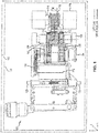
- FIG. 1 a power drive unit (PDU) 100 is shown in a lowered configuration.
- An X-Y-Z axis is shown throughout the drawings to illustrate the relative position of components.
- the PDU 100 can be used in a cargo bay 152 of an aircraft 150 for moving one or more unit load device (ULD) relative to the cargo bay 152.
- ULD unit load device
- a ULD can include any cargo unit to be stored in the cargo bay 152 during flight.
- the PDU 100 can include one or more tires 118 that rotate, causing movement of the ULD in a particular direction.
- the PDU 100 may be positioned adjacent to an entrance of the cargo bay 152, and in that regard, the PDU 100 may be designed to move a ULD along the X axis and along the Y axis. Stated differently, the PDU 100 may be designed to move the ULD forward/aft and laterally relative to the aircraft 150. In order to accomplish both of these movements, the PDU 100 can be controlled to lower itself below the conveyor plane and then to have an orthogonally-oriented PDU raise itself above the conveyor plane.
- the PDU 100 may be raised above the conveyor plane to transport a ULD along the Y axis, such as from a door of a cargo bay into the cargo bay. After the ULD is in the cargo bay, the PDU 100 can lower itself below the conveyor plane, while an adjacent PDU raises itself above the conveyor plane for transporting the ULD along the X axis.
- the PDU 100 can include a motor 102.
- the motor 102 can convert electrical power into mechanical power.
- the motor 102 can generate mechanical power that is transferred through a first stage gear 103 into a planetary gear set 105.
- a drag clutch 104 is coupled to the planetary gear set 105 and controls the operation of the planetary gear set 105. Stated differently, the drag clutch 104 controls the distribution of mechanical power to components of the PDU 100.
- the power is transferred through the planetary gear set 105 to a ring gear 110 and to a carrier gear 114.
- a cam shaft 109 rotates in response to rotation of the ring gear 110.
- a lift cam 108 is actuated, causing the PDU 100 to rotate about a pin 120 towards the positive Z direction (i.e., the PDU 100 rotates in the forward direction).
- the lift cam 108 reaches a physical stop which restricts further rotation of the lift cam 108.
- the PDU 100 is in a raised position such that the tire 118 of the PDU 100 is above the conveyor plane.
- the output shaft 119 is coupled to the tire 118 that rotates along with the output shaft 119.
- the ULD In order to move a ULD, the ULD is positioned on the tire 118. Friction between the tire 118 and the ULD causes the ULD to move in a predetermined direction in response to rotation of the tire 118.
- the output shaft 119 continues to receive mechanical power to drive the tire 118.
- the motor 102 can rotate in the reverse direction, causing the cam shaft 109 to rotate in the reverse direction. This causes the PDU 100 to become lowered below the conveyor plane.
- the position at the lowered state is determined by the input of the rotary encoder to the controller and rotating the rotor a specific amount of rotations which is based on the gear ratio of the gear set, or by input of the optional encoder detecting the position of the cam shaft.
- a PDU 200 is designed to have the ability to remain in the raised position in response to electrical power being removed from the PDU 200.
- the PDU 200 is shown to be in the raised position (i.e., rotated 90 degrees about the Y axis relative to the PDU 100).
- the permanent magnet motor 202 can include any type of permanent magnet motor such as an interior permanent magnet motor (IPM), a surface permanent magnet motor (SPM), a brushless direct current (DC) motor or any other similar type of motor that provides cogging torque.
- the permanent magnet motor 202 can include a rotor 228 configured to rotate about an axis A.
- the permanent magnet motor 202 can also include a stator 226 configured to remain stationary relative to the axis A.
- Permanent magnets 229 may be embedded within the rotor 228 and may create a constant magnetic field.
- Windings 227 connected to an AC power supply may be positioned within the stator 226.
- the windings 227 may receive AC power and may generate a magnetic field in response, such that the magnetic field changes as the phase of the power changes.
- This rotating magnetic field may attract and/or repel the permanent magnets 229 of the rotor 228, causing the rotor 228 to rotate about the axis A.
- the angular velocity of the rotor 228, the amount of torque applied to the rotor 228 and the direction of rotation of the rotor 228 can be adjusted by controlling the amplitude, frequency and phase of the power signal.
- the permanent magnets 229 are not dependent upon current, they continue to generate a magnetic field in response to power being removed from the permanent magnet motor 202. In this state, the magnetic field of the permanent magnets 229 can attract and/or repel metallic portions 225 of the stator 226. This stationary force (due to this attraction/repulsion) resists rotation of the rotor 228 relative to the axis A. This force may be referred to as a cogging torque.
- the permanent magnet motor 202 is designed to have sufficient cogging torque to ensure that the PDU 200 remains in the raised position in response to power being removed from the PDU 200.
- the rotor 228 may be coupled to a planetary gear set 205.
- the planetary gear set 205 may be coupled to a cam shaft 209 via a drag clutch 204 and may also be coupled to an output shaft 216 via the drag clutch 204.
- the drag clutch 204 may be used to control the couplings of the planetary gear set 205 to operatively couple the rotor 228 to a cam shaft 209 and/or to operatively couple the rotor 228 to the output shaft 216.
- the output shaft 216 may be coupled to a tire 231.
- the tire 231 may extend beyond the conveyor plane 230 in the positive Z direction.
- the output shaft 216 may rotate, resulting in rotation of the tire 231. This rotation of the tire may cause a ULD that is in contact with the tire 231 to move relative to the PDU 200.
- the PDU 200 will drive the ULD along the X axis.
- the cam shaft 209 may rotate in response to forward rotation of the rotor 228 when the rotor 228 is coupled to the cam shaft 209, causing a lift cam to rotate the PDU 200 into the raised position.
- a downward force exerted on the PDU 200 (such as from a ULD) can be translated via the planetary gear set 205 to the rotor 228.
- the entire gear set 240 of the PDU 200, including the planetary gear set 205, can have a 60 to 1 (60:1) to 85:1 gear ratio.
- This downward force can cause reverse rotation of an induction motor and may be sufficient to overcome the cogging torque of the permanent magnet motor 202 alone.
- the cogging torque of the permanent magnet motor 202 is multiplied by the gear ratio of the planetary gear set 205, resulting in sufficient reflected inertia to resist this reverse rotation of the rotor 228. This reflected inertia is sufficient to cause the PDU 200 to remain in the raised position even when the power is removed from the PDU 200.
- the PDU 200 may include one or more sensors or encoders, such as a rotary encoder 224 configured to determine the angular position of the rotor 228 relative to the stator 226 and/or an optional encoder 222 configured to determine the angular position of the cam shaft 209 relative to the conveyor plane 230.
- the angular position of the rotor 228 relative to the stator 226 can be used by a controller, such as a controller 300 of FIG. 3 , to determine the angular position of the cam shaft 209 (and, thus, the PDU 200) relative to the conveyor plane 230. Based on this information, the controller can determine whether the PDU 200 is in the raised position, the lowered position or a position in between.
- the optional encoder 222 can detect the angular position of the cam shaft 209 relative to the conveyor plane 230. Using the determined or detected position of the cam shaft 209 relative to the conveyor plane 230, the controller can properly control the cam shaft 209 to cause the PDU 200 to be in the raised or the lowered position, as desired.
- the controller 300 may be adapted to perform a method 301 for controlling the angular position of the cam shaft and, thus, for controlling the angular position of the PDU 200 relative to the conveyor plane 230.
- the controller 300 may receive a request for the PDU 200 to be in the raised position or the lowered position.
- the request may be received from a user interface operatively coupled to the controller 300.
- the controller can receive the angular position of the rotor 228 relative to the stator 226 and/or the position of the cam shaft 209 relative to the conveyor plane 230. Based on this information, the controller 300 can determine a current angular position of the PDU 200 relative to the conveyor plane 230 and, thus, whether the PDU 200 is in the raised position, the lowered position or in between.
- the controller 300 can control the PDU 200 based on the detected or determined angular position of the PDU 200 relative to the conveyor plane 230.
- the controller 300 can cause the rotor 228 to be operatively coupled to the cam shaft 209 and can control the power applied to the windings 227 of the stator 226 to control the position of the PDU 200 relative to the conveyor plane 230.
- the permanent magnet motor can be a 4 pole, 12 slot surface permanent magnet motor.
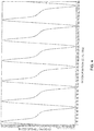
- FIG. 4 illustrates the cogging torque of the permanent magnet motor 202 based on the rotational position of the rotor 228. As shown, the cogging torque can range between negative 0,1271 Nm (18 ounce-inches (-18 oz-in, -1.30 kilogram-centimeters (kg-cm))) and 0,1271 Nm (18 oz-in (1.30 kg-cm)) based on the angular position of the rotor 228 relative to the stator 226. 0,1271 Nm (18 oz-in) is approximately 20 percent (20%) of the torque available when the permanent magnet motor 202 is excited and is sufficient to cause the PDU 200 to remain in the raised position in response to removal of power.
- references to "one embodiment”, “an embodiment”, “an example embodiment”, etc. indicate that the embodiment described may include a particular feature, structure, or characteristic, but every embodiment may not necessarily include the particular feature, structure, or characteristic. Moreover, such phrases are not necessarily referring to the same embodiment. Further, when a particular feature, structure, or characteristic is described in connection with an embodiment, it is submitted that it is within the knowledge of one skilled in the art to affect such feature, structure, or characteristic in connection with other embodiments whether or not explicitly described. After reading the description, it will be apparent to one skilled in the relevant art(s) how to implement the disclosure in alternative embodiments.
Landscapes
- Engineering & Computer Science (AREA)
- Power Engineering (AREA)
- General Engineering & Computer Science (AREA)
- Mechanical Engineering (AREA)
- Aviation & Aerospace Engineering (AREA)
- Microelectronics & Electronic Packaging (AREA)
- Control Of Motors That Do Not Use Commutators (AREA)
- Connection Of Motors, Electrical Generators, Mechanical Devices, And The Like (AREA)
Claims (10)
- Kraftantriebseinheit, PDU, zum Bewegen von Fracht relativ zu einem Frachtraum (152) eines Luftfahrzeugs (150), umfassend:eine Nockenwelle (109);einen Hebenocken (108), der an die Nockenwelle gekoppelt und konfiguriert ist, um zu bewirken, dass sich die PDU (100) in zumindest einer von einer angehobenen Position oder einer abgesenkten Position befindet, auf Grundlage von Rotation der Nockenwelle; undeinen Permanentmagnetmotor (102), der konfiguriert ist, um ein pulsierendes Drehmoment zu erzeugen, das ausreichend ist, um Rotation der Nockenwelle zu widerstehen, sodass die PDU als Reaktion darauf, dass Kraft von dem Permanentmagnetmotor entfernt wird, in der angehobenen Position bleibt,wobei die PDU ferner einen Planetengetriebesatz (105) umfasst, der konfiguriert ist, um an den Permanentmagnetmotor und an die Nockenwelle gekoppelt zu sein, sodass mechanische Kraft von dem Permanentmagnetmotor über den Planetengetriebesatz auf die Nockenwelle übergehen kann und sodass ein Getriebeverhältnis des Planetengetriebesatzes das pulsierende Drehmoment des Permanentmagnetmotors multipliziert, um reflektierte Trägheit zu erzeugen,wobei die PDU ferner eine Abtriebswelle (119) umfasst, die an den Permanentmagnetmotor und an den Planetengetriebesatz gekoppelt ist, sodass mechanische Kraft von dem Permanentmagnetmotor über den Planetengetriebesatz auf die Abtriebswelle übergehen kann, undeine Schleppkupplung (204), die an den Planetengetriebesatz gekoppelt und konfiguriert ist, um die Kopplung zwischen der Nockenwelle und dem Planetengetriebesatz und zwischen der Abtriebswelle und dem Planetengetriebesatz zu steuern.
- PDU nach Anspruch 1, wobei der Permanentmagnetmotor zumindest eines von einem inneren Permanentmagnetmotor, einem Oberflächenpermanentmagnetmotor oder einem bürstenlosen Gleichstrom-(DC-)Motor beinhaltet.
- PDU nach Anspruch 1, wobei der Permanentmagnetmotor konfiguriert ist, um ungefähr 0,1271 Nm (18 Unzen-Zoll) an pulsierendem Drehmoment zu erzeugen.
- PDU nach Anspruch 1, ferner umfassend eine Steuerung (300), die an den Permanentmagnetmotor gekoppelt und konfiguriert ist, um Rotation eines Rotors des Permanentmagnetmotors zu steuern.
- PDU nach Anspruch 1, wobei ein vollständiger Getriebesatz der PDU ein Getriebeverhältnis zwischen 60 zu 1 (60:1) und 85 zu 1 (85:1) aufweist.
- PDU nach einem vorhergehenden Anspruch, ferner umfassend einen Drehgeber (224) und wobei der Permanentmagnetmotor einen Rotor (228) und einen Stator (226) beinhaltet und der Drehgeber konfiguriert ist, um eine Winkelposition des Rotors relativ zu dem Stator zu erfassen.
- PDU nach Anspruch 5, ferner umfassend eine Steuerung, die konfiguriert ist, um eine Winkelposition der PDU relativ zu der Förderebene auf Grundlage von durch den Drehgeber erfassten Daten zu bestimmen.
- Luftfahrzeugfrachtsystem, umfassend:einen Frachtraum (152); undeine Kraftantriebseinheit, PDU, (100) nach einem vorhergehenden Anspruch zum Bewegen von Fracht.
- Luftfahrzeugfrachtsystem nach Anspruch 8, wobei die PDU ferner einen optionalen Encoder beinhaltet, der konfiguriert ist, um eine Winkelposition der Nockenwelle relativ zu der Förderebene zu erfassen.
- Verfahren zur Steuerung des Betriebs einer Kraftantriebseinheit, PDU, eines Luftfahrzeugs, umfassend:Empfangen, durch eine Steuerung, einer Forderung, dass sich die PDU in einer angehobenen Position oder in einer abgesenkten Position befindet;Empfangen, durch die Steuerung, von Daten entsprechend einer aktuellen Winkelposition der PDU relativ zu einer Förderebene; undSteuern, durch die Steuerung, eines Motors, sodass sich die PDU auf Grundlage der Daten entsprechend der aktuellen Winkelposition der PDU in der angehobenen Position oder der abgesenkten Position befindet, wobei die PDU die Merkmale nach Anspruch 1 umfasst.
Applications Claiming Priority (1)
| Application Number | Priority Date | Filing Date | Title |
|---|---|---|---|
| US14/937,562 US9878789B2 (en) | 2015-11-10 | 2015-11-10 | Lift and hold differential lift PDU utilizing a permanent magnet rotor |
Publications (2)
| Publication Number | Publication Date |
|---|---|
| EP3168151A1 EP3168151A1 (de) | 2017-05-17 |
| EP3168151B1 true EP3168151B1 (de) | 2019-01-02 |
Family
ID=57249743
Family Applications (1)
| Application Number | Title | Priority Date | Filing Date |
|---|---|---|---|
| EP16197692.3A Active EP3168151B1 (de) | 2015-11-10 | 2016-11-08 | Hebe- und haltedifferentialaufzugs-pdu mit einem permanentmagnetrotor |
Country Status (2)
| Country | Link |
|---|---|
| US (1) | US9878789B2 (de) |
| EP (1) | EP3168151B1 (de) |
Families Citing this family (3)
| Publication number | Priority date | Publication date | Assignee | Title |
|---|---|---|---|---|
| CN109973609A (zh) * | 2019-03-12 | 2019-07-05 | 游晓东 | 一种机械动作转换器 |
| US11628936B2 (en) | 2019-04-17 | 2023-04-18 | Goodrich Corporation | Wireless mobile maintenance display unit and system for cargo handling system |
| US12319437B2 (en) | 2022-06-07 | 2025-06-03 | Goodrich Corporation | Dual-rotor self-lift power drive unit |
Family Cites Families (9)
| Publication number | Priority date | Publication date | Assignee | Title |
|---|---|---|---|---|
| US4746843A (en) * | 1985-01-25 | 1988-05-24 | Adept Technology, Inc. | Motor control circuit and drive amplifier for a permanent magnet DC torque motor |
| DE4102424C3 (de) | 1991-01-28 | 2000-08-24 | Telair Int Gmbh | Antriebsrolleneinheit |
| EP0497045B1 (de) | 1991-01-30 | 1995-02-22 | Teleflex Incorporated | Rollenantriebseinheit für eine Förderbahn |
| US5661384A (en) * | 1995-06-05 | 1997-08-26 | Lucas Western, Inc. | Motor control system and method |
| US5716028A (en) | 1995-10-20 | 1998-02-10 | Vickers, Inc. | Aircraft cargo handling |
| US6420846B1 (en) * | 1999-10-19 | 2002-07-16 | Lucas Western Inc. | Power drive unit with stall sensor |
| EP1620312B1 (de) | 2003-05-02 | 2007-09-19 | Ancra International, Llc | Lenkbare /einziehbare frachtkraftantriebseinheit |
| US7199543B1 (en) * | 2005-12-13 | 2007-04-03 | Goodrich Corporation | Power drive unit with unit load device sensor |
| US7777385B2 (en) | 2008-05-15 | 2010-08-17 | Honeywell International Inc. | Compact, electromagnetically braked actuator assembly |
-
2015
- 2015-11-10 US US14/937,562 patent/US9878789B2/en active Active
-
2016
- 2016-11-08 EP EP16197692.3A patent/EP3168151B1/de active Active
Non-Patent Citations (1)
| Title |
|---|
| None * |
Also Published As
| Publication number | Publication date |
|---|---|
| US9878789B2 (en) | 2018-01-30 |
| EP3168151A1 (de) | 2017-05-17 |
| US20170129606A1 (en) | 2017-05-11 |
Similar Documents
| Publication | Publication Date | Title |
|---|---|---|
| EP3551535B1 (de) | Hubgebläsepositionarretierungsmechanismus | |
| EP3168151B1 (de) | Hebe- und haltedifferentialaufzugs-pdu mit einem permanentmagnetrotor | |
| EP3205577B1 (de) | Magnetische ausrichtungsarretierung | |
| US9694978B2 (en) | Cargo handling system | |
| CN109153502B (zh) | 具有无传感器或传感器整流的集成电机驱动器/控制器 | |
| JP2018070155A5 (de) | ||
| US12097947B2 (en) | Propulsion unit with foldable propeller blades and method for folding the blades | |
| CN116133943A (zh) | 具有可折叠螺旋桨叶片的推进单元和用于将螺旋桨停止在分度角位置的方法 | |
| US20250035663A1 (en) | Systems and methods for starting a sensorless motor | |
| EP3392516B1 (de) | Elektromotorischer stellantrieb | |
| EP3174179B1 (de) | Wirbelstromrepulsionsmotor | |
| CN105270609A (zh) | 用于管理电马达的方法 | |
| EP3838756A1 (de) | Solenoid-/magnethaltebremse mit abschaltmagnethaltefunktion | |
| EP4293874A3 (de) | Elektromotorantriebseinheit für ein flugzeugladeraumbodensystem | |
| EP4321432A1 (de) | Elektromagnetische haltebremse mit haltefunktion für einen ausschaltmagneten | |
| CN211685606U (zh) | 一种螺旋桨定向锁紧机构 | |
| EP3355463A1 (de) | Verfahren zur betätigung einer bremse an einem hebezug durch elektromagnetische mittel in einem permanentmagnetmotor | |
| CN105946590A (zh) | 一种全轮独立驱动有感无刷电动车制动的装置及方法 | |
| NZ753969B2 (en) | Lift fan position lock mechanism | |
| HK40013963A (en) | Lift fan position lock mechanism |
Legal Events
| Date | Code | Title | Description |
|---|---|---|---|
| PUAI | Public reference made under article 153(3) epc to a published international application that has entered the european phase |
Free format text: ORIGINAL CODE: 0009012 |
|
| STAA | Information on the status of an ep patent application or granted ep patent |
Free format text: STATUS: THE APPLICATION HAS BEEN PUBLISHED |
|
| AK | Designated contracting states |
Kind code of ref document: A1 Designated state(s): AL AT BE BG CH CY CZ DE DK EE ES FI FR GB GR HR HU IE IS IT LI LT LU LV MC MK MT NL NO PL PT RO RS SE SI SK SM TR |
|
| AX | Request for extension of the european patent |
Extension state: BA ME |
|
| STAA | Information on the status of an ep patent application or granted ep patent |
Free format text: STATUS: REQUEST FOR EXAMINATION WAS MADE |
|
| 17P | Request for examination filed |
Effective date: 20171117 |
|
| RBV | Designated contracting states (corrected) |
Designated state(s): AL AT BE BG CH CY CZ DE DK EE ES FI FR GB GR HR HU IE IS IT LI LT LU LV MC MK MT NL NO PL PT RO RS SE SI SK SM TR |
|
| RIC1 | Information provided on ipc code assigned before grant |
Ipc: H02K 1/27 20060101ALI20180417BHEP Ipc: H02K 11/21 20160101ALI20180417BHEP Ipc: H02K 7/116 20060101ALI20180417BHEP Ipc: B64D 9/00 20060101AFI20180417BHEP Ipc: B65G 13/06 20060101ALI20180417BHEP Ipc: F16H 37/12 20060101ALI20180417BHEP |
|
| GRAP | Despatch of communication of intention to grant a patent |
Free format text: ORIGINAL CODE: EPIDOSNIGR1 |
|
| STAA | Information on the status of an ep patent application or granted ep patent |
Free format text: STATUS: GRANT OF PATENT IS INTENDED |
|
| INTG | Intention to grant announced |
Effective date: 20180605 |
|
| GRAS | Grant fee paid |
Free format text: ORIGINAL CODE: EPIDOSNIGR3 |
|
| GRAA | (expected) grant |
Free format text: ORIGINAL CODE: 0009210 |
|
| STAA | Information on the status of an ep patent application or granted ep patent |
Free format text: STATUS: THE PATENT HAS BEEN GRANTED |
|
| AK | Designated contracting states |
Kind code of ref document: B1 Designated state(s): AL AT BE BG CH CY CZ DE DK EE ES FI FR GB GR HR HU IE IS IT LI LT LU LV MC MK MT NL NO PL PT RO RS SE SI SK SM TR |
|
| REG | Reference to a national code |
Ref country code: GB Ref legal event code: FG4D |
|
| REG | Reference to a national code |
Ref country code: CH Ref legal event code: EP Ref country code: AT Ref legal event code: REF Ref document number: 1084035 Country of ref document: AT Kind code of ref document: T Effective date: 20190115 |
|
| REG | Reference to a national code |
Ref country code: IE Ref legal event code: FG4D |
|
| REG | Reference to a national code |
Ref country code: DE Ref legal event code: R096 Ref document number: 602016008916 Country of ref document: DE |
|
| REG | Reference to a national code |
Ref country code: NL Ref legal event code: MP Effective date: 20190102 |
|
| REG | Reference to a national code |
Ref country code: LT Ref legal event code: MG4D |
|
| REG | Reference to a national code |
Ref country code: AT Ref legal event code: MK05 Ref document number: 1084035 Country of ref document: AT Kind code of ref document: T Effective date: 20190102 |
|
| PG25 | Lapsed in a contracting state [announced via postgrant information from national office to epo] |
Ref country code: NL Free format text: LAPSE BECAUSE OF FAILURE TO SUBMIT A TRANSLATION OF THE DESCRIPTION OR TO PAY THE FEE WITHIN THE PRESCRIBED TIME-LIMIT Effective date: 20190102 |
|
| PG25 | Lapsed in a contracting state [announced via postgrant information from national office to epo] |
Ref country code: PT Free format text: LAPSE BECAUSE OF FAILURE TO SUBMIT A TRANSLATION OF THE DESCRIPTION OR TO PAY THE FEE WITHIN THE PRESCRIBED TIME-LIMIT Effective date: 20190502 Ref country code: FI Free format text: LAPSE BECAUSE OF FAILURE TO SUBMIT A TRANSLATION OF THE DESCRIPTION OR TO PAY THE FEE WITHIN THE PRESCRIBED TIME-LIMIT Effective date: 20190102 Ref country code: PL Free format text: LAPSE BECAUSE OF FAILURE TO SUBMIT A TRANSLATION OF THE DESCRIPTION OR TO PAY THE FEE WITHIN THE PRESCRIBED TIME-LIMIT Effective date: 20190102 Ref country code: LT Free format text: LAPSE BECAUSE OF FAILURE TO SUBMIT A TRANSLATION OF THE DESCRIPTION OR TO PAY THE FEE WITHIN THE PRESCRIBED TIME-LIMIT Effective date: 20190102 Ref country code: SE Free format text: LAPSE BECAUSE OF FAILURE TO SUBMIT A TRANSLATION OF THE DESCRIPTION OR TO PAY THE FEE WITHIN THE PRESCRIBED TIME-LIMIT Effective date: 20190102 Ref country code: NO Free format text: LAPSE BECAUSE OF FAILURE TO SUBMIT A TRANSLATION OF THE DESCRIPTION OR TO PAY THE FEE WITHIN THE PRESCRIBED TIME-LIMIT Effective date: 20190402 Ref country code: ES Free format text: LAPSE BECAUSE OF FAILURE TO SUBMIT A TRANSLATION OF THE DESCRIPTION OR TO PAY THE FEE WITHIN THE PRESCRIBED TIME-LIMIT Effective date: 20190102 |
|
| PG25 | Lapsed in a contracting state [announced via postgrant information from national office to epo] |
Ref country code: LV Free format text: LAPSE BECAUSE OF FAILURE TO SUBMIT A TRANSLATION OF THE DESCRIPTION OR TO PAY THE FEE WITHIN THE PRESCRIBED TIME-LIMIT Effective date: 20190102 Ref country code: GR Free format text: LAPSE BECAUSE OF FAILURE TO SUBMIT A TRANSLATION OF THE DESCRIPTION OR TO PAY THE FEE WITHIN THE PRESCRIBED TIME-LIMIT Effective date: 20190403 Ref country code: HR Free format text: LAPSE BECAUSE OF FAILURE TO SUBMIT A TRANSLATION OF THE DESCRIPTION OR TO PAY THE FEE WITHIN THE PRESCRIBED TIME-LIMIT Effective date: 20190102 Ref country code: IS Free format text: LAPSE BECAUSE OF FAILURE TO SUBMIT A TRANSLATION OF THE DESCRIPTION OR TO PAY THE FEE WITHIN THE PRESCRIBED TIME-LIMIT Effective date: 20190502 Ref country code: BG Free format text: LAPSE BECAUSE OF FAILURE TO SUBMIT A TRANSLATION OF THE DESCRIPTION OR TO PAY THE FEE WITHIN THE PRESCRIBED TIME-LIMIT Effective date: 20190402 Ref country code: RS Free format text: LAPSE BECAUSE OF FAILURE TO SUBMIT A TRANSLATION OF THE DESCRIPTION OR TO PAY THE FEE WITHIN THE PRESCRIBED TIME-LIMIT Effective date: 20190102 |
|
| REG | Reference to a national code |
Ref country code: DE Ref legal event code: R097 Ref document number: 602016008916 Country of ref document: DE |
|
| PG25 | Lapsed in a contracting state [announced via postgrant information from national office to epo] |
Ref country code: EE Free format text: LAPSE BECAUSE OF FAILURE TO SUBMIT A TRANSLATION OF THE DESCRIPTION OR TO PAY THE FEE WITHIN THE PRESCRIBED TIME-LIMIT Effective date: 20190102 Ref country code: IT Free format text: LAPSE BECAUSE OF FAILURE TO SUBMIT A TRANSLATION OF THE DESCRIPTION OR TO PAY THE FEE WITHIN THE PRESCRIBED TIME-LIMIT Effective date: 20190102 Ref country code: CZ Free format text: LAPSE BECAUSE OF FAILURE TO SUBMIT A TRANSLATION OF THE DESCRIPTION OR TO PAY THE FEE WITHIN THE PRESCRIBED TIME-LIMIT Effective date: 20190102 Ref country code: AT Free format text: LAPSE BECAUSE OF FAILURE TO SUBMIT A TRANSLATION OF THE DESCRIPTION OR TO PAY THE FEE WITHIN THE PRESCRIBED TIME-LIMIT Effective date: 20190102 Ref country code: RO Free format text: LAPSE BECAUSE OF FAILURE TO SUBMIT A TRANSLATION OF THE DESCRIPTION OR TO PAY THE FEE WITHIN THE PRESCRIBED TIME-LIMIT Effective date: 20190102 Ref country code: AL Free format text: LAPSE BECAUSE OF FAILURE TO SUBMIT A TRANSLATION OF THE DESCRIPTION OR TO PAY THE FEE WITHIN THE PRESCRIBED TIME-LIMIT Effective date: 20190102 Ref country code: DK Free format text: LAPSE BECAUSE OF FAILURE TO SUBMIT A TRANSLATION OF THE DESCRIPTION OR TO PAY THE FEE WITHIN THE PRESCRIBED TIME-LIMIT Effective date: 20190102 Ref country code: SK Free format text: LAPSE BECAUSE OF FAILURE TO SUBMIT A TRANSLATION OF THE DESCRIPTION OR TO PAY THE FEE WITHIN THE PRESCRIBED TIME-LIMIT Effective date: 20190102 |
|
| PLBE | No opposition filed within time limit |
Free format text: ORIGINAL CODE: 0009261 |
|
| STAA | Information on the status of an ep patent application or granted ep patent |
Free format text: STATUS: NO OPPOSITION FILED WITHIN TIME LIMIT |
|
| PG25 | Lapsed in a contracting state [announced via postgrant information from national office to epo] |
Ref country code: SM Free format text: LAPSE BECAUSE OF FAILURE TO SUBMIT A TRANSLATION OF THE DESCRIPTION OR TO PAY THE FEE WITHIN THE PRESCRIBED TIME-LIMIT Effective date: 20190102 |
|
| 26N | No opposition filed |
Effective date: 20191003 |
|
| PG25 | Lapsed in a contracting state [announced via postgrant information from national office to epo] |
Ref country code: SI Free format text: LAPSE BECAUSE OF FAILURE TO SUBMIT A TRANSLATION OF THE DESCRIPTION OR TO PAY THE FEE WITHIN THE PRESCRIBED TIME-LIMIT Effective date: 20190102 |
|
| PG25 | Lapsed in a contracting state [announced via postgrant information from national office to epo] |
Ref country code: TR Free format text: LAPSE BECAUSE OF FAILURE TO SUBMIT A TRANSLATION OF THE DESCRIPTION OR TO PAY THE FEE WITHIN THE PRESCRIBED TIME-LIMIT Effective date: 20190102 |
|
| REG | Reference to a national code |
Ref country code: CH Ref legal event code: PL |
|
| PG25 | Lapsed in a contracting state [announced via postgrant information from national office to epo] |
Ref country code: LI Free format text: LAPSE BECAUSE OF NON-PAYMENT OF DUE FEES Effective date: 20191130 Ref country code: LU Free format text: LAPSE BECAUSE OF NON-PAYMENT OF DUE FEES Effective date: 20191108 Ref country code: MC Free format text: LAPSE BECAUSE OF FAILURE TO SUBMIT A TRANSLATION OF THE DESCRIPTION OR TO PAY THE FEE WITHIN THE PRESCRIBED TIME-LIMIT Effective date: 20190102 Ref country code: CH Free format text: LAPSE BECAUSE OF NON-PAYMENT OF DUE FEES Effective date: 20191130 |
|
| REG | Reference to a national code |
Ref country code: BE Ref legal event code: MM Effective date: 20191130 |
|
| PG25 | Lapsed in a contracting state [announced via postgrant information from national office to epo] |
Ref country code: IE Free format text: LAPSE BECAUSE OF NON-PAYMENT OF DUE FEES Effective date: 20191108 |
|
| PG25 | Lapsed in a contracting state [announced via postgrant information from national office to epo] |
Ref country code: BE Free format text: LAPSE BECAUSE OF NON-PAYMENT OF DUE FEES Effective date: 20191130 |
|
| PG25 | Lapsed in a contracting state [announced via postgrant information from national office to epo] |
Ref country code: CY Free format text: LAPSE BECAUSE OF FAILURE TO SUBMIT A TRANSLATION OF THE DESCRIPTION OR TO PAY THE FEE WITHIN THE PRESCRIBED TIME-LIMIT Effective date: 20190102 |
|
| GBPC | Gb: european patent ceased through non-payment of renewal fee |
Effective date: 20201108 |
|
| PG25 | Lapsed in a contracting state [announced via postgrant information from national office to epo] |
Ref country code: HU Free format text: LAPSE BECAUSE OF FAILURE TO SUBMIT A TRANSLATION OF THE DESCRIPTION OR TO PAY THE FEE WITHIN THE PRESCRIBED TIME-LIMIT; INVALID AB INITIO Effective date: 20161108 Ref country code: MT Free format text: LAPSE BECAUSE OF FAILURE TO SUBMIT A TRANSLATION OF THE DESCRIPTION OR TO PAY THE FEE WITHIN THE PRESCRIBED TIME-LIMIT Effective date: 20190102 |
|
| PG25 | Lapsed in a contracting state [announced via postgrant information from national office to epo] |
Ref country code: GB Free format text: LAPSE BECAUSE OF NON-PAYMENT OF DUE FEES Effective date: 20201108 |
|
| PG25 | Lapsed in a contracting state [announced via postgrant information from national office to epo] |
Ref country code: MK Free format text: LAPSE BECAUSE OF FAILURE TO SUBMIT A TRANSLATION OF THE DESCRIPTION OR TO PAY THE FEE WITHIN THE PRESCRIBED TIME-LIMIT Effective date: 20190102 |
|
| P01 | Opt-out of the competence of the unified patent court (upc) registered |
Effective date: 20230522 |
|
| PGFP | Annual fee paid to national office [announced via postgrant information from national office to epo] |
Ref country code: DE Payment date: 20251022 Year of fee payment: 10 |
|
| PGFP | Annual fee paid to national office [announced via postgrant information from national office to epo] |
Ref country code: FR Payment date: 20251022 Year of fee payment: 10 |