EP3168008A2 - Powered nail driver with a nail placement assembly - Google Patents
Powered nail driver with a nail placement assembly Download PDFInfo
- Publication number
- EP3168008A2 EP3168008A2 EP16196931.6A EP16196931A EP3168008A2 EP 3168008 A2 EP3168008 A2 EP 3168008A2 EP 16196931 A EP16196931 A EP 16196931A EP 3168008 A2 EP3168008 A2 EP 3168008A2
- Authority
- EP
- European Patent Office
- Prior art keywords
- nail
- tip
- lifter
- guide groove
- driving tool
- Prior art date
- Legal status (The legal status is an assumption and is not a legal conclusion. Google has not performed a legal analysis and makes no representation as to the accuracy of the status listed.)
- Granted
Links
Images




Classifications
-
- B—PERFORMING OPERATIONS; TRANSPORTING
- B25—HAND TOOLS; PORTABLE POWER-DRIVEN TOOLS; MANIPULATORS
- B25C—HAND-HELD NAILING OR STAPLING TOOLS; MANUALLY OPERATED PORTABLE STAPLING TOOLS
- B25C1/00—Hand-held nailing tools; Nail feeding devices
- B25C1/008—Safety devices
-
- B—PERFORMING OPERATIONS; TRANSPORTING
- B25—HAND TOOLS; PORTABLE POWER-DRIVEN TOOLS; MANIPULATORS
- B25C—HAND-HELD NAILING OR STAPLING TOOLS; MANUALLY OPERATED PORTABLE STAPLING TOOLS
- B25C1/00—Hand-held nailing tools; Nail feeding devices
- B25C1/001—Nail feeding devices
-
- B—PERFORMING OPERATIONS; TRANSPORTING
- B25—HAND TOOLS; PORTABLE POWER-DRIVEN TOOLS; MANIPULATORS
- B25C—HAND-HELD NAILING OR STAPLING TOOLS; MANUALLY OPERATED PORTABLE STAPLING TOOLS
- B25C1/00—Hand-held nailing tools; Nail feeding devices
- B25C1/06—Hand-held nailing tools; Nail feeding devices operated by electric power
-
- B—PERFORMING OPERATIONS; TRANSPORTING
- B25—HAND TOOLS; PORTABLE POWER-DRIVEN TOOLS; MANIPULATORS
- B25C—HAND-HELD NAILING OR STAPLING TOOLS; MANUALLY OPERATED PORTABLE STAPLING TOOLS
- B25C1/00—Hand-held nailing tools; Nail feeding devices
- B25C1/08—Hand-held nailing tools; Nail feeding devices operated by combustion pressure
- B25C1/10—Hand-held nailing tools; Nail feeding devices operated by combustion pressure generated by detonation of a cartridge
- B25C1/18—Details and accessories, e.g. splinter guards, spall minimisers
- B25C1/188—Arrangements at the forward end of the barrel, e.g. splinter guards, spall minimisers, safety arrangements, silencers, bolt retainers
-
- B—PERFORMING OPERATIONS; TRANSPORTING
- B25—HAND TOOLS; PORTABLE POWER-DRIVEN TOOLS; MANIPULATORS
- B25C—HAND-HELD NAILING OR STAPLING TOOLS; MANUALLY OPERATED PORTABLE STAPLING TOOLS
- B25C1/00—Hand-held nailing tools; Nail feeding devices
-
- B—PERFORMING OPERATIONS; TRANSPORTING
- B25—HAND TOOLS; PORTABLE POWER-DRIVEN TOOLS; MANIPULATORS
- B25C—HAND-HELD NAILING OR STAPLING TOOLS; MANUALLY OPERATED PORTABLE STAPLING TOOLS
- B25C5/00—Manually operated portable stapling tools; Hand-held power-operated stapling tools; Staple feeding devices therefor
- B25C5/16—Staple-feeding devices, e.g. with feeding means, supports for staples or accessories concerning feeding devices
-
- B—PERFORMING OPERATIONS; TRANSPORTING
- B25—HAND TOOLS; PORTABLE POWER-DRIVEN TOOLS; MANIPULATORS
- B25C—HAND-HELD NAILING OR STAPLING TOOLS; MANUALLY OPERATED PORTABLE STAPLING TOOLS
- B25C7/00—Accessories for nailing or stapling tools, e.g. supports
Definitions
- the present disclosure relates generally to the field of powered nail drivers, and more particularly to a cordless or battery-powered nail driver nail with a nail placement or positioning assembly for use in construction framing.
- a nail driving tool with a nail placement or positioning assembly can have a nose housing assembly including a forward nail guide housing coupled to a rear nail guide housing and defining a nail driving path therebetween.
- a nail driver can be positioned and reciprocally movably along a nail driver axis to drive a nail down the nail driving path.
- a trip arm can be movably coupled to the nose housing assembly and movable between an extended non-trip position and a retracted trip position.
- a replaceable positioning tip can be removably fixedly coupled to a distal end of the trip arm.
- the replaceable positioning tip can define a tip nail guide groove having a proximal portion extending a first angle that is substantially parallel to the nail driver axis and a tapered distal end tapering at a second angle.
- the tapered distal end can be encompassed by a thin-walled portion of the replaceable positioning tip.
- a nail tip lifter can be pivotably coupled to the rear nail guide housing for pivotable movement between a first position adjacent the positioning tip and a second position away from the positioning tip.
- the nail tip lifter can define a lifter nail guide groove extending from a proximal end to a distal end of the lifter nail guide groove.
- a biasing member can be positioned between the rear nail guide housing and the nail tip lifter to bias the nail tip lifter toward the first position.
- Figs. 1-13 relate to one example embodiment of a nail driving tool 20 with a nail placement or positioning assembly 22 in accordance with the present disclosure.
- the nail driving tool 20 can be a framing nailer. Additionally or alternatively, the nail driving tool 20 can be a cordless nailer powered by a portable battery 24.
- the battery 24 can be a 40 volt or greater battery, a 60 volt or greater battery, or even an 80 volt or greater battery.
- the nail placement assembly 22 can include a nose housing assembly 26 including a forward nail guide housing 28 coupled to a rear nail guide housing 30 and defining a nail driving path 32 therebetween.
- a nail driver 34 is positioned and reciprocally movably along a nail driver axis 36 to drive a nail 38 down the nail driving path 32.
- a magazine 25 for successively feeding nails 38 to the nose housing assembly 26 can be coupled to the rear nail guide housing 30.
- a trip arm 40 can be movably coupled to the nose housing assembly 26 and movable between an extended non-trip position ( Fig. 9 ) and a retracted trip position ( Fig. 10 ).
- a replaceable positioning tip 42 can be removably fixedly coupled to a distal end 44 of the trip arm 40.
- the replaceable positioning tip 42 can include a flat extension 48 which can further include an extending tab 54 defined or bounded by three positioning sides or surfaces 56.
- the distal end 44 of the trip arm 40 can include a tip-receiving channel 46 into which the flat extension 48 of the positioning tip 42 can be friction fit with the cooperating positioning surfaces 52, 56 engaged against each other.
- the tip-receiving channel 46 can further include a tab slot 50 defined or bounded by three positioning sides or surfaces 52.
- a removable pin 58 can extend through apertures 60 through the tip-receiving channel 46 of the trim arm 40 aligned with an aperture 62 of the extension 48 of the positioning tip 42.
- a rubber grommet 64 or other removable fastener can be mounted on the pin 58 to selectively retain the pin 58 in the apertures 60, 62.
- the pin 58 retains the cooperating positioning surfaces 52, 56 against each other.
- the positioning tip 42 can be fixedly coupled to the trip arm 40 for movement therewith, and without relative movement therebetween.
- the replaceable positioning tip 42 can define a tip nail guide groove 66 having a proximal portion 68 and a tapered distal end 70.
- the proximal portion 68 of the tip nail guide groove 66 can extend at a first angle that is substantially parallel to the nail driver axis 36.
- the tapered distal end 70 of the tip nail guide groove 66 can taper at a second angle relative to the nail driver axis 36. In some cases, this second angle of the tapered distal end 70 of the tip nail guide groove 66 can be from about 5 degrees to about 8 degrees relative to the nail driver axis 36.
- the tapered distal end 70 of the tip nail guide groove 66 can be encompassed by a thin-walled portion 72 of the replaceable positioning tip 42.
- the thickness of the thin-walled portion 72 encompassing the tapered distal end 70 and adjacent the proximal portion can be about equal to or less than a maximum depth of the proximal portion 68 of the tip nail guide groove 66.
- the thickness of the thin-walled portion 72 encompassing the tapered distal end 70 can taper from a first thickness adjacent the proximal portion 68 of the tip nail guide groove 66 to a second thickness away from the proximal portion 68 that is smaller than the first thickness.
- An axial length of the tapered distal end 70 of the tip nail guide groove 66 can be less than about 25% of an aligned axial length of the proximal portion 68 of the tip nail guide groove 66.
- a nail tip lifter 74 can be pivotably coupled to the rear nail guide housing 30 for pivotable movement between a first position adjacent the positioning tip 42 ( Fig. 9 ) and a second position away from the positioning tip 42 (e.g., Figs. 13 and 14 ).
- the nail tip lifter 74 defines a lifter nail guide groove 76.
- the lifter nail guide groove 76 starts at a proximal end or start end 78 and extends to a distal end or terminal end 80.
- the nail tip lifter 74 can have a projecting stop 82 that engages against a cooperating stop 84 of the rear nail guide housing 30. Engagement of the stops 82, 84 can position the nail tip lifter 74 in non-contacting relationship to the replaceable positioning tip 42 when the nail tip lifter is in the first position.
- the stop 82 of the nail tip lifter 74 can be positioned away from the positioning tip 42.
- the stop 82 can be positioned adjacent the proximal end 78 of the rear guide groove 76.
- a biasing member 86 can be positioned between the rear nail guide housing 30 and the nail tip lifter 74 to bias the stop 82 against the corresponding of cooperating stop 84 when the nail tip lifter 74 is in the first position ( Fig. 9 ).
- the biasing member 86 can be a resilient foam material.
- the resilient foam material forming the biasing member 86 can be a microcellular polyurethane elastomer.
- One example of such a microcellular polyurethane elastomer is sold under the trade name Celasto® and can be purchased from BASF, Lemforde, Germany.
- the lifter guide groove 76 of the nail tip lifter 74 can have an initial concave arc portion 88 extending from the proximal end 78 of the groove 76.
- the lifter guide groove 76 can have a terminal straight portion 90 extending from and adjacent the distal end 80 of the groove 76.
- An intermediate convex transition portion 92 can be provided between the initial concave arc portion 88 and the straight portions 90.
- the length of the intermediate convex transition portion 92 along a center line of the lifter guide groove 76 can be between about 1 and 2 times the length of the terminal straight portion 90. In some cases, the length of the initial concave arc portion 88 along a center line of the lifter guide groove 76 can be at least 3 times, at least 4 times, and at least 5 times the length of the terminal straight portion 90 of the of the rear guide groove 76. Alternatively or additionally, the radius defining the initial concave arc portion 88 can, in some cases, be from about 25 mm to about 35 mm.
- the tip lifter 74 can be pivotably mounted to the rear nail guide housing 30 via a pivot pin 75.
- the distal end 80 of the lifter nail guide groove 76 and of the tip lifter 74 can be positioned closer to the tapered distal end 70 of the positioning tip 42 when the trip arm 40 is in the retracted trip position ( Fig. 10 ), than when the trip arm 40 is in the extended non-trip position ( Fig. 9 ).
- Fig. 10 shows the positioning tip 42 located within a fastener or nail aperture 94 of a metal framing component 96 and with the trip arm 40 in the extended, non-trip position.
- the nail driving tool 20 will not operate to drive a nail 38 down the nail driving path 32, even when the trigger 98 of the nail driving tool is depressed.
- Fig. 11 shows the positioning tip 42 located within a fastener or nail aperture 94 of a metal framing component 96 and with the trip arm 40 in the retracted, trip position.
- the nail driving tool 20 will operate to drive a nail 38 down the nail driving path 32 when the trigger 98 of the nail driving tool is also depressed.
- Fig. 12 shows a nail 38 that has been driven down the nail driving path 32 to a position where the pointed tip of the nail 38 is aligned with, or engaging, the tapered.
- the nail has been guided initially by the forward and rear nail guide housings, 28 and 30, respectively, and further by the opposing tip nail guide groove 66 and lifter nail guide groove 76 of the positioning tip 42 and the nail tip lifter 74, respectively.
- the resilient foam biasing member 86 has been found to be a particularly robust and effective biasing member 86 to sufficiently bias the tip lifter 74 toward the positioning tip 42 to minimize the chance that any wayward pointed tip of the driven nail 38 is lifted to engage against the positioning tip nail guide groove 76 and its tapered distal end 70. This helps insure very precise positioning of the driven nail 38. Because the positioning tip 42 was positioned within the aperture 94 when the trigger 98 was depressed, the driven nail 38 is properly positioned within the aperture 94 of the metal framing component 96.
- Fig. 13 shows the nail head 39 and/or nail driver 34 initially engaging the nail tip lifter 74.
- the nail tip lifter 74 is moved further from its first position away from the positioning tip 42 and toward its second position.
- Fig. 14 shows this continued movement of the nail tip lifter 74 into its second position as the nail driver 34 is fully extended and the nail 38 if fully driven through the nail aperture 94 and into the wooden framing member 99 with the nail head 39 fully engaged against the metal framing component 96.
- Fig. 15 shows a driven nail that has wandered or tumbled out of alignment with the nail driver axis 36 or with the corresponding axis of the nail driving path 32.
- the arcuate shape of the lifter nail guide groove 76 has been found to be particularly effective at redirecting the driven nail 38 back into alignment with the nail driver axis 36 and against the positioning tip 42 and into the tip nail guide groove 66 as previously described.
- the concave arc portion 88 of the lifter nail guide groove 76 extends from the inception, or proximal end 78 of the groove 76 and is relatively long, with only a relatively short convex transition portion 92 and straight portion 90.
- This shape maximizes the possibility that any such wayward nail 38 will engage the concave arc portion 88.
- This concave arc portion 88 as described above, has been found to be particularly effective at redirecting any such wayward nail 38.
- the only other portion of the lifter nail guide groove 76 that a wayward nail 38 could initially contact is the relatively short convex transition portion 92.
- the convex transition portion 92 is short and limited to a position very close to or adjacent the positioning tip 42, in the event a wayward nail 38 should initially strike the lifter nail guide groove 76 here, it would be in need of only a relatively small amount of repositioning, which the convex transition portion 92 is capable of doing.
- the rubber grommet 64 can be removed from the retention groove 59 of the pin 58 retaining the positioning tip 42 on the trip arm 40. Then, the pin 58 can be removed from the apertures 60, 62. The positioning tip 42 can then be removed by pulling it axially out of the tip-receiving channel 46. This axial movement of the positioning tip 42 helps minimize interference or engagement with adjacent components during removal and insertion. A replacement positioning tip 42 can then be reinserted into the tip-receiving channel 46 by reversing this process.
- first, second, third, etc. may be used herein to distinguish various commonly named features, these terms are only used to distinguish between the otherwise commonly named features. Thus, terms such as “first,” “second,” and other numerical terms when used herein do not imply an importance, sequence or order unless clearly indicated by the context. Thus, a first feature below could be termed a second reature without departing from the teachings of the example embodiments.
Landscapes
- Engineering & Computer Science (AREA)
- Mechanical Engineering (AREA)
- Chemical & Material Sciences (AREA)
- Combustion & Propulsion (AREA)
- Portable Nailing Machines And Staplers (AREA)
Abstract
Description
- The present disclosure relates generally to the field of powered nail drivers, and more particularly to a cordless or battery-powered nail driver nail with a nail placement or positioning assembly for use in construction framing.
- This section provides background information related to the present disclosure which is not necessarily prior art.
- There is a need in construction framing to use battery-powered framing nailers to precisely fasten metal joist hangers, metal hurricane ties, strappings, and other metal components to framing members. Fastening such metal components involves driving the nail through a nail opening in the metal component. Typically, powered framing nailers tend to obscure the nail opening, which makes it very difficult to properly align the nail ejection opening of the nailer with the nail opening.
- This section provides a general summary of the disclosure, and is not a comprehensive disclosure of its full scope or all of its features.
- In accordance with one aspect of the present disclosure, a nail driving tool with a nail placement or positioning assembly is provided. The nail placement assembly can have a nose housing assembly including a forward nail guide housing coupled to a rear nail guide housing and defining a nail driving path therebetween. A nail driver can be positioned and reciprocally movably along a nail driver axis to drive a nail down the nail driving path. A trip arm can be movably coupled to the nose housing assembly and movable between an extended non-trip position and a retracted trip position. A replaceable positioning tip can be removably fixedly coupled to a distal end of the trip arm. The replaceable positioning tip can define a tip nail guide groove having a proximal portion extending a first angle that is substantially parallel to the nail driver axis and a tapered distal end tapering at a second angle. The tapered distal end can be encompassed by a thin-walled portion of the replaceable positioning tip. A nail tip lifter can be pivotably coupled to the rear nail guide housing for pivotable movement between a first position adjacent the positioning tip and a second position away from the positioning tip. The nail tip lifter can define a lifter nail guide groove extending from a proximal end to a distal end of the lifter nail guide groove. A biasing member can be positioned between the rear nail guide housing and the nail tip lifter to bias the nail tip lifter toward the first position.
- Further areas of applicability will become apparent from the description provided herein. The description and specific examples in this summary are intended for purposes of illustration only and are not intended to limit the scope of the present disclosure.
- The drawings described herein are for illustrative purposes only of selected embodiments and not all possible implementations, and are not intended to limit the scope of the present disclosure.
-
Fig. 1 is one example of a powered nail driver with a nail placement or positioning assembly in accordance with the present disclosure. -
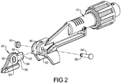
Fig. 2 is an exploded perspective view of the trip arm and positioning tip of the powered nail driver ofFig. 1 . -
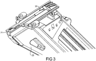
Fig. 3 is a perspective view of the rear nail guide housing and magazine of the powered nail driver ofFig. 1 . -
Fig. 4 is a perspective view of the replaceable positioning tip of the powered nail driver ofFig. 1 . -
Fig. 5 is a side elevation view of the replaceable positioning tip ofFig. 4 . -
Fig. 6 is a cross section view taken along line 6-6Fig. 5 . -
Fig. 7 is a cross section view taken along line 7-7Fig. 5 . -
Fig. 8 is a perspective view of the nail tip lifter of the powered nail driver ofFig. 1 . -
Fig. 9 is a cross section view of the nail tip lifter ofFig. 8 . -
Fig. 10 is a cross section view including the nail placement or positioning assembly ofFig. 1 , showing the positioning tip located within an aperture of a metal framing component and with the trip arm in the extended, non-trip position. -
Fig. 11 is a cross section view similar toFig. 10 , but showing the trip arm in the retracted, trip position. -
Fig. 12 is a cross section view similar toFig. 11 , but showing the nail initially positioned within the aperture of the metal framing component. -
Fig. 13 is a cross section view similar toFig. 12 , but showing the nail head and/or nail driver initially engaging the nail tip lifter. -
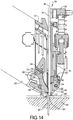
Fig. 14 is a cross section view similar toFig. 13 , but showing the nail driver fully extended and engaging the nail tip lifter. -
Fig. 15 is a cross section view similar to the previous figures, but showing a nail tip of an angled nail engaging the nail tip lifter prior to the nail tip lifter repositioning the nail tip against the replaceable positioning tip. - Corresponding reference numerals indicate corresponding parts throughout the several views of the drawings.
- Example embodiments will now be described more fully with reference to the accompanying drawings. While aspects of the present disclosure are described herein and illustrated in the accompanying drawings in the context of a battery-powered framing nailer, those of ordinary skill in the art will appreciate that the invention, in its broadest aspects, has further applicability.
-
Figs. 1-13 relate to one example embodiment of anail driving tool 20 with a nail placement orpositioning assembly 22 in accordance with the present disclosure. Thenail driving tool 20 can be a framing nailer. Additionally or alternatively, thenail driving tool 20 can be a cordless nailer powered by aportable battery 24. Thebattery 24 can be a 40 volt or greater battery, a 60 volt or greater battery, or even an 80 volt or greater battery. - The
nail placement assembly 22 can include anose housing assembly 26 including a forwardnail guide housing 28 coupled to a rearnail guide housing 30 and defining anail driving path 32 therebetween. Anail driver 34 is positioned and reciprocally movably along anail driver axis 36 to drive anail 38 down thenail driving path 32. Amagazine 25 for successively feedingnails 38 to thenose housing assembly 26 can be coupled to the rearnail guide housing 30. - A
trip arm 40 can be movably coupled to thenose housing assembly 26 and movable between an extended non-trip position (Fig. 9 ) and a retracted trip position (Fig. 10 ). Areplaceable positioning tip 42 can be removably fixedly coupled to a distal end 44 of thetrip arm 40. For example, thereplaceable positioning tip 42 can include aflat extension 48 which can further include an extendingtab 54 defined or bounded by three positioning sides orsurfaces 56. - The distal end 44 of the
trip arm 40 can include a tip-receivingchannel 46 into which theflat extension 48 of thepositioning tip 42 can be friction fit with thecooperating positioning surfaces channel 46 can further include atab slot 50 defined or bounded by three positioning sides orsurfaces 52. Aremovable pin 58 can extend throughapertures 60 through the tip-receivingchannel 46 of thetrim arm 40 aligned with anaperture 62 of theextension 48 of thepositioning tip 42. - A
rubber grommet 64 or other removable fastener can be mounted on thepin 58 to selectively retain thepin 58 in theapertures pin 58 retains the cooperatingpositioning surfaces positioning tip 42 can be fixedly coupled to thetrip arm 40 for movement therewith, and without relative movement therebetween. - The
replaceable positioning tip 42 can define a tipnail guide groove 66 having aproximal portion 68 and a tapereddistal end 70. Theproximal portion 68 of the tipnail guide groove 66 can extend at a first angle that is substantially parallel to thenail driver axis 36. The tapereddistal end 70 of the tipnail guide groove 66 can taper at a second angle relative to thenail driver axis 36. In some cases, this second angle of the tapereddistal end 70 of the tipnail guide groove 66 can be from about 5 degrees to about 8 degrees relative to thenail driver axis 36. - The tapered
distal end 70 of the tipnail guide groove 66 can be encompassed by a thin-walledportion 72 of thereplaceable positioning tip 42. The thickness of the thin-walledportion 72 encompassing the tapereddistal end 70 and adjacent the proximal portion can be about equal to or less than a maximum depth of theproximal portion 68 of the tipnail guide groove 66. - The thickness of the thin-walled
portion 72 encompassing the tapereddistal end 70 can taper from a first thickness adjacent theproximal portion 68 of the tipnail guide groove 66 to a second thickness away from theproximal portion 68 that is smaller than the first thickness. An axial length of the tapereddistal end 70 of the tipnail guide groove 66 can be less than about 25% of an aligned axial length of theproximal portion 68 of the tipnail guide groove 66. - A
nail tip lifter 74 can be pivotably coupled to the rearnail guide housing 30 for pivotable movement between a first position adjacent the positioning tip 42 (Fig. 9 ) and a second position away from the positioning tip 42 (e.g.,Figs. 13 and14 ). Thenail tip lifter 74 defines a lifternail guide groove 76. The lifternail guide groove 76 starts at a proximal end or startend 78 and extends to a distal end orterminal end 80. - The
nail tip lifter 74 can have a projectingstop 82 that engages against a cooperatingstop 84 of the rearnail guide housing 30. Engagement of thestops nail tip lifter 74 in non-contacting relationship to thereplaceable positioning tip 42 when the nail tip lifter is in the first position. Thestop 82 of thenail tip lifter 74 can be positioned away from thepositioning tip 42. Thestop 82 can be positioned adjacent theproximal end 78 of therear guide groove 76. - A biasing
member 86 can be positioned between the rear nail guidehousing 30 and thenail tip lifter 74 to bias thestop 82 against the corresponding of cooperatingstop 84 when thenail tip lifter 74 is in the first position (Fig. 9 ). The biasingmember 86 can be a resilient foam material. For example, the resilient foam material forming the biasingmember 86 can be a microcellular polyurethane elastomer. One example of such a microcellular polyurethane elastomer is sold under the trade name Celasto® and can be purchased from BASF, Lemforde, Germany. - The
lifter guide groove 76 of thenail tip lifter 74 can have an initialconcave arc portion 88 extending from theproximal end 78 of thegroove 76. Thelifter guide groove 76 can have a terminalstraight portion 90 extending from and adjacent thedistal end 80 of thegroove 76. An intermediateconvex transition portion 92 can be provided between the initialconcave arc portion 88 and thestraight portions 90. - In some cases, the length of the intermediate
convex transition portion 92 along a center line of thelifter guide groove 76 can be between about 1 and 2 times the length of the terminalstraight portion 90. In some cases, the length of the initialconcave arc portion 88 along a center line of thelifter guide groove 76 can be at least 3 times, at least 4 times, and at least 5 times the length of the terminalstraight portion 90 of the of therear guide groove 76. Alternatively or additionally, the radius defining the initialconcave arc portion 88 can, in some cases, be from about 25 mm to about 35 mm. - The
tip lifter 74 can be pivotably mounted to the rear nail guidehousing 30 via apivot pin 75. Thedistal end 80 of the lifternail guide groove 76 and of thetip lifter 74 can be positioned closer to the tapereddistal end 70 of thepositioning tip 42 when thetrip arm 40 is in the retracted trip position (Fig. 10 ), than when thetrip arm 40 is in the extended non-trip position (Fig. 9 ). -
Fig. 10 shows thepositioning tip 42 located within a fastener ornail aperture 94 of ametal framing component 96 and with thetrip arm 40 in the extended, non-trip position. When thetrip arm 40 is in this extended, non-trip position, thenail driving tool 20 will not operate to drive anail 38 down thenail driving path 32, even when the trigger 98 of the nail driving tool is depressed. -
Fig. 11 shows thepositioning tip 42 located within a fastener ornail aperture 94 of ametal framing component 96 and with thetrip arm 40 in the retracted, trip position. When thetrip arm 40 is in this retracted, trip position, thenail driving tool 20 will operate to drive anail 38 down thenail driving path 32 when the trigger 98 of the nail driving tool is also depressed. -
Fig. 12 shows anail 38 that has been driven down thenail driving path 32 to a position where the pointed tip of thenail 38 is aligned with, or engaging, the tapered. Along the way, the nail has been guided initially by the forward and rear nail guide housings, 28 and 30, respectively, and further by the opposing tipnail guide groove 66 and lifternail guide groove 76 of thepositioning tip 42 and thenail tip lifter 74, respectively. The resilientfoam biasing member 86 has been found to be a particularly robust and effective biasingmember 86 to sufficiently bias thetip lifter 74 toward thepositioning tip 42 to minimize the chance that any wayward pointed tip of the drivennail 38 is lifted to engage against the positioning tipnail guide groove 76 and its tapereddistal end 70. This helps insure very precise positioning of the drivennail 38. Because thepositioning tip 42 was positioned within theaperture 94 when the trigger 98 was depressed, the drivennail 38 is properly positioned within theaperture 94 of themetal framing component 96. -
Fig. 13 shows the nail head 39 and/ornail driver 34 initially engaging thenail tip lifter 74. As the nail head 39 andnail driver 34 continues its downward movement, thenail tip lifter 74 is moved further from its first position away from thepositioning tip 42 and toward its second position.Fig. 14 shows this continued movement of thenail tip lifter 74 into its second position as thenail driver 34 is fully extended and thenail 38 if fully driven through thenail aperture 94 and into the wooden framingmember 99 with the nail head 39 fully engaged against themetal framing component 96. -
Fig. 15 shows a driven nail that has wandered or tumbled out of alignment with thenail driver axis 36 or with the corresponding axis of thenail driving path 32. The arcuate shape of the lifternail guide groove 76 has been found to be particularly effective at redirecting the drivennail 38 back into alignment with thenail driver axis 36 and against thepositioning tip 42 and into the tipnail guide groove 66 as previously described. - For example, the
concave arc portion 88 of the lifternail guide groove 76 extends from the inception, orproximal end 78 of thegroove 76 and is relatively long, with only a relatively shortconvex transition portion 92 andstraight portion 90. This shape maximizes the possibility that any suchwayward nail 38 will engage theconcave arc portion 88. Thisconcave arc portion 88 as described above, has been found to be particularly effective at redirecting any suchwayward nail 38. In essence, the only other portion of the lifternail guide groove 76 that awayward nail 38 could initially contact is the relatively shortconvex transition portion 92. Because theconvex transition portion 92 is short and limited to a position very close to or adjacent thepositioning tip 42, in the event awayward nail 38 should initially strike the lifternail guide groove 76 here, it would be in need of only a relatively small amount of repositioning, which theconvex transition portion 92 is capable of doing. - Should the
positioning tip 42 become damaged or otherwise in need of replacement, therubber grommet 64 can be removed from theretention groove 59 of thepin 58 retaining thepositioning tip 42 on thetrip arm 40. Then, thepin 58 can be removed from theapertures positioning tip 42 can then be removed by pulling it axially out of the tip-receivingchannel 46. This axial movement of thepositioning tip 42 helps minimize interference or engagement with adjacent components during removal and insertion. Areplacement positioning tip 42 can then be reinserted into the tip-receivingchannel 46 by reversing this process. - Although the terms first, second, third, etc. may be used herein to distinguish various commonly named features, these terms are only used to distinguish between the otherwise commonly named features. Thus, terms such as "first," "second," and other numerical terms when used herein do not imply an importance, sequence or order unless clearly indicated by the context. Thus, a first feature below could be termed a second reature without departing from the teachings of the example embodiments.
- It will be appreciated that the above description is merely exemplary in nature and is not intended to limit the present disclosure, its application or uses. While specific examples have been described in the specification and illustrated in the drawings, it will be understood by those of ordinary skill in the art that various changes may be made and equivalents may be substituted for elements thereof without departing from the scope of the present disclosure. Furthermore, the mixing and matching of features, elements and/or functions between various examples is expressly contemplated herein, even if not specifically shown or described, so that one of ordinary skill in the art would appreciate from this disclosure that features, elements and/or functions of one example may be incorporated into another example as appropriate, unless described otherwise, above. Moreover, many modifications may be made to adapt a particular situation or material to the teachings of the present disclosure without departing from the essential scope thereof. Therefore, it is intended that the present disclosure not be limited to the particular examples illustrated by the drawings and described in the specification as the best mode presently contemplated for carrying out the teachings of the present disclosure, but that the scope of the present disclosure will include any embodiments falling within the foregoing description.
Claims (15)
- A nail driving tool with a nail placement assembly, the nail placement assembly comprising: a nose housing assembly including a forward nail guide housing coupled to a rear nail guide housing and defining a nail driving path therebetween; a nail driver positioned and reciprocally movably along a nail driver axis to drive a nail down the nail driving path; and a trip arm movably coupled to the nose housing assembly and movable between an extended non-trip position and a retracted trip position characterized by:a replaceable positioning tip removably fixedly coupled to a distal end of the trip arm, the replaceable positioning tip defining a tip nail guide groove having a proximal portion extending a first angle that is substantially parallel to the nail driver axis and a tapered distal end tapering at a second angle and encompassed by a thin-walled portion of the replaceable positioning tip;a nail tip lifter pivotably coupled to the rear nail guide housing for pivotable movement between a first position adjacent the positioning tip and a second position away from the positioning tip, the nail tip lifter defining a lifter nail guide groove extending from a proximal end to a distal end of the lifter nail guide groove; anda biasing member positioned between the rear nail guide housing and the nail tip lifter and biasing the nail tip lifter toward the first position.
- The nail driving tool with a nail placement assembly according to claim 1, characterized in that the biasing member is a resilient foam material; and optionally, is a microcellular polyurethane elastomer foam material.
- The nail driving tool with a nail placement assembly according to claim 1 or claim 2, characterized in that the lifter guide groove of the nail tip lifter has an initial concave arc portion extending from the proximal end of the groove and a terminal straight portion extending from and adjacent the distal end of the lifter guide groove and an intermediate convex transition portion between the concave arc and straight portions.
- The nail driving tool with a nail placement assembly according to claim 3, characterized in that a length of the initial concave arc portion is at least three times a length of the terminal straight portion of the of the lifter guide groove.
- The nail driving tool with a nail placement assembly according to claim 3, characterized in that a radius defining the initial concave arc portion is from about 25 mm to about 35 mm.
- The nail driving tool with a nail placement assembly according to any of claims 1 to 5, characterized in that the nail tip lifter has a stop positioned away from the positioning tip and adjacent the proximal end of the lifter guide groove, and the stop engages against a cooperating stop of the rear nail guide housing to position the nail tip lifter in non-contacting relationship to the replaceable positioning tip when the nail tip lifter is in the first position, and the biasing member biases the stop against the corresponding stop when the nail tip lifter is in the first position.
- The nail driving tool with a nail placement assembly according to any of claims 1 to 6, characterized in that a distal end of the trip arm comprises a tip-receiving channel, and the positioning tip comprises an extension friction fit into the tip-receiving channel.
- The nail driving tool with a nail placement assembly according to any of claims 1 to 7, characterized in that the positioning tip comprises at least one positioning surface engageable against at least one corresponding positioning surface of the trip arm; and optionally, the at least one positioning surface of the positioning tip is provided by three sides of a tab of the extension, and the at least one corresponding positioning surface of the trip arm is provided by three corresponding sides of a tab slot of the channel.
- The nail driving tool with a nail placement assembly according to any of claims 7 or 8, characterized by a removable pin extending through aligned apertures through the tip-receiving channel and through the positioning tip extension; and optionally, a rubber grommet retaining the removable pin in the aligned apertures.
- The nail driving tool with a nail placement assembly according to any of claims 1 to 9, characterized in that the second angle of the tapered distal end of the tip nail guide groove is from about 5 degrees to about 8 degrees relative to the nail driver axis.
- The nail driving tool with a nail placement assembly according to any of claims 1 to 10, characterized in that a thickness of the thin-walled portion encompassing the tapered distal end of tip nail guide groove and adjacent the proximal portion is less than a maximum depth of the proximal portion of the tip nail guide groove.
- The nail driving tool with a nail placement assembly according to any of claims 1 to 11, characterized in that a thickness of the thin-walled portion encompassing the distal end tapers from a first thickness adjacent the proximal portion of the tip nail guide groove to a second thickness smaller that the first thickness away from the proximal portion of the tip nail guide groove.
- The nail driving tool with a nail placement assembly according to any of claims 1 to 12, characterized in that an axial length of the tapered distal end of the tip nail guide groove is less than 25% of an aligned axial length of the proximal end of the tip nail guide groove.
- The nail driving tool with a nail placement assembly according to any of claims 1 to 13, characterized in that the nail driving tool is a framing nailer.
- The nail driving tool with a nail placement assembly according to any of claims 1 to 14, characterized in that the nail driving tool is a cordless nailer powered by a 40 volt or greater battery; preferably by a 60 volt or greater battery; and more preferably by a 80 volt or greater battery.
Applications Claiming Priority (2)
| Application Number | Priority Date | Filing Date | Title |
|---|---|---|---|
| US201562249648P | 2015-11-02 | 2015-11-02 | |
| US15/339,543 US10350741B2 (en) | 2015-11-02 | 2016-10-31 | Powered nail driver with a nail placement assembly |
Publications (3)
| Publication Number | Publication Date |
|---|---|
| EP3168008A2 true EP3168008A2 (en) | 2017-05-17 |
| EP3168008A3 EP3168008A3 (en) | 2017-07-19 |
| EP3168008B1 EP3168008B1 (en) | 2020-01-29 |
Family
ID=57223576
Family Applications (1)
| Application Number | Title | Priority Date | Filing Date |
|---|---|---|---|
| EP16196931.6A Active EP3168008B1 (en) | 2015-11-02 | 2016-11-02 | Powered nail driver with a nail placement assembly |
Country Status (2)
| Country | Link |
|---|---|
| US (1) | US10350741B2 (en) |
| EP (1) | EP3168008B1 (en) |
Families Citing this family (8)
| Publication number | Priority date | Publication date | Assignee | Title |
|---|---|---|---|---|
| TWM517078U (en) * | 2015-10-02 | 2016-02-11 | 鑽全實業股份有限公司 | Nail gun with protective structure |
| DE102020122342B4 (en) | 2020-08-26 | 2026-03-19 | Raimund Beck Nageltechnik Gmbh | Nail setting device and kit for attaching to a nail setting device |
| US12162125B2 (en) | 2020-10-30 | 2024-12-10 | Milwaukee Electric Tool Corporation | Powered fastener driver |
| WO2022113643A1 (en) * | 2020-11-26 | 2022-06-02 | 工機ホールディングス株式会社 | Work machine |
| TWI757183B (en) * | 2021-05-19 | 2022-03-01 | 永大霖企業股份有限公司 | Nail gun that doesn't slide easily |
| DE112023000567T5 (en) | 2022-02-18 | 2025-01-30 | Milwaukee Electric Tool Corporation | POWERED FASTENER DRIVER |
| US12515303B2 (en) | 2023-05-05 | 2026-01-06 | Milwaukee Electric Tool Corporation | Powered fastener driver |
| US20240375257A1 (en) * | 2023-05-12 | 2024-11-14 | Illinois Tool Works Inc. | Apparatus for driving fasteners |
Family Cites Families (33)
| Publication number | Priority date | Publication date | Assignee | Title |
|---|---|---|---|---|
| US3134981A (en) * | 1962-06-04 | 1964-06-02 | United Shoe Machinery Corp | Fastener inserting tools |
| US3398446A (en) * | 1963-09-17 | 1968-08-27 | Sandvikens Jernberks Aktiebola | Device for applying traction-augmenting studs in tires for vehicles and the like |
| US3854648A (en) * | 1972-10-04 | 1974-12-17 | G Inzoli | Air operated fastener driving tool, especially for tacks |
| US4065045A (en) * | 1976-12-01 | 1977-12-27 | Flexible Steel Lacing Company | Fastener driver tool |
| GB1603826A (en) * | 1977-05-20 | 1981-12-02 | Fisco Products Ltd | Nozzle assmbly for a nail guilding tool |
| JPS5648482U (en) | 1979-09-20 | 1981-04-30 | ||
| DE3715293A1 (en) | 1987-05-08 | 1988-12-01 | Haubold Kihlberg Gmbh | Device for driving-in fastening means |
| US5238167A (en) | 1992-10-09 | 1993-08-24 | Illinois Tool Works Inc. | Positioning mechanism for powered fastener-driving tool |
| US5452835A (en) | 1994-08-01 | 1995-09-26 | Illinois Tool Works Inc. | Positioning mechanism for powered fastener-driving tool |
| JPH08229847A (en) * | 1995-02-28 | 1996-09-10 | Max Co Ltd | Attachment for box nailing machine |
| JP2000218567A (en) * | 1999-02-02 | 2000-08-08 | Makita Corp | Nail driving machine |
| US6279808B1 (en) | 1999-07-27 | 2001-08-28 | Mark E. Larsen | Nail guide mechanism for a nail gun |
| JP3780822B2 (en) * | 2000-05-23 | 2006-05-31 | 日立工機株式会社 | Nailer |
| WO2003031124A1 (en) * | 2001-10-03 | 2003-04-17 | Max Kabushiki Kaisha | Fastener magazine of fastening machine |
| US6808101B2 (en) * | 2002-05-24 | 2004-10-26 | Illinois Tool Works Inc. | Framing tool with automatic fastener-size adjustment |
| US6739490B1 (en) | 2002-06-24 | 2004-05-25 | Illinois Tool Works Inc. | Fastener supply and positioning mechanism for a tool |
| WO2004033126A1 (en) | 2002-09-13 | 2004-04-22 | Daimlerchrysler Ag | Press-hardened part and method for the production thereof |
| US6789718B2 (en) | 2002-09-17 | 2004-09-14 | Stanley Fastening Systems, L.P. | Nail placement device |
| US6783044B2 (en) | 2003-02-05 | 2004-08-31 | Stanley Fastening Systems, L.P. | Depth of drive adjustment for a fastener driving tool with removable contact member and method of exchanging contact members |
| JP4348995B2 (en) | 2003-05-08 | 2009-10-21 | マックス株式会社 | Nail launch guide mechanism in nailing machine |
| JP4420205B2 (en) | 2004-04-28 | 2010-02-24 | マックス株式会社 | Nail guide device for nailing machine |
| US7017790B1 (en) * | 2004-09-22 | 2006-03-28 | Wei-Chih Peng | Positioning device of a nail driver |
| US7255256B2 (en) * | 2005-03-03 | 2007-08-14 | Stanley Fastening Systems, L.P. | Finish nailer with contoured contact trip foot |
| JP4400587B2 (en) | 2006-03-16 | 2010-01-20 | 日立工機株式会社 | Driving machine |
| CN101205531A (en) | 2006-12-19 | 2008-06-25 | 中国人民解放军军事医学科学院野战输血研究所 | Fetus liver stroma cell strain expressing alkaline fibroblast growth factor and uses thereof |
| CN106077210A (en) | 2007-05-25 | 2016-11-09 | 麦格纳国际公司 | Integrated die trim and method |
| US8931676B2 (en) | 2007-08-27 | 2015-01-13 | Black & Decker Inc. | Nailer having mechanism for pre-positioning nail |
| FR2920332B1 (en) * | 2007-09-05 | 2010-04-23 | Spit Soc Prospect Inv Techn | FIXING TOOL FOR FIXING ELEMENTS OF DIFFERENT LENGTHS |
| FR2931380B1 (en) | 2008-05-26 | 2010-08-20 | Prospection Et D Inventsions T | FLEXIBLE FIXING TOOL WITH FLEXIBLE BLADE |
| JP2011206856A (en) * | 2010-03-29 | 2011-10-20 | Makita Corp | Driving tool |
| WO2012065090A1 (en) | 2010-11-12 | 2012-05-18 | Illinois Tool Works Inc. | Fastener -driving tool |
| JP5998847B2 (en) | 2012-10-25 | 2016-09-28 | マックス株式会社 | Nailer |
| US9527196B2 (en) * | 2013-11-06 | 2016-12-27 | Illinois Tool Works Inc. | Fastener driving tool with an automatic nose chamber guide member |
-
2016
- 2016-10-31 US US15/339,543 patent/US10350741B2/en active Active
- 2016-11-02 EP EP16196931.6A patent/EP3168008B1/en active Active
Non-Patent Citations (1)
| Title |
|---|
| None |
Also Published As
| Publication number | Publication date |
|---|---|
| US20170120432A1 (en) | 2017-05-04 |
| EP3168008B1 (en) | 2020-01-29 |
| US10350741B2 (en) | 2019-07-16 |
| EP3168008A3 (en) | 2017-07-19 |
Similar Documents
| Publication | Publication Date | Title |
|---|---|---|
| EP3168008B1 (en) | Powered nail driver with a nail placement assembly | |
| US20190154070A1 (en) | Fastening Device | |
| EP0591671A1 (en) | Positioning mechanism for powered fastener-driving tool | |
| EP2002935A2 (en) | Magazine assembly for nailer | |
| US6286742B1 (en) | Nail driving tool | |
| EP3366426A2 (en) | Contact trip having magnetic filter | |
| GB2318540A (en) | Staple gun tacker | |
| US20120073148A1 (en) | Clamp for reciprocating saw | |
| KR20070114275A (en) | Power nailer with driver blade blocking mechanism in the magazine | |
| EP2450154A2 (en) | Stapler | |
| EP1584416B1 (en) | Fastening tool | |
| JP4577495B2 (en) | Driving guide mechanism for screw and nail driving machines | |
| US20190224817A1 (en) | Pipe pliers | |
| US8146788B2 (en) | Fastening tool with releasable work contact element | |
| EP1726858A1 (en) | Part fixing tool and nailing device | |
| US11679480B2 (en) | Nosepiece latch mechanism for a fastening tool | |
| US11077542B2 (en) | Metal connector adaptor for a fastening tool | |
| JP5354839B2 (en) | Floor nailing machine | |
| JP5218330B2 (en) | Impact tool | |
| JP2007168006A (en) | Nailing mechanism of floor nailing machine | |
| AU2019200014B2 (en) | Pipe Pliers | |
| EP3000561A2 (en) | Metal connector adaptor for a fastening tool | |
| JP6638259B2 (en) | Driving tool | |
| CA2919789C (en) | Staple tool | |
| KR100866634B1 (en) | Blade of Taka device with warp prevention structure of Taka pin |
Legal Events
| Date | Code | Title | Description |
|---|---|---|---|
| PUAI | Public reference made under article 153(3) epc to a published international application that has entered the european phase |
Free format text: ORIGINAL CODE: 0009012 |
|
| STAA | Information on the status of an ep patent application or granted ep patent |
Free format text: STATUS: THE APPLICATION HAS BEEN PUBLISHED |
|
| AK | Designated contracting states |
Kind code of ref document: A2 Designated state(s): AL AT BE BG CH CY CZ DE DK EE ES FI FR GB GR HR HU IE IS IT LI LT LU LV MC MK MT NL NO PL PT RO RS SE SI SK SM TR |
|
| AX | Request for extension of the european patent |
Extension state: BA ME |
|
| PUAL | Search report despatched |
Free format text: ORIGINAL CODE: 0009013 |
|
| AK | Designated contracting states |
Kind code of ref document: A3 Designated state(s): AL AT BE BG CH CY CZ DE DK EE ES FI FR GB GR HR HU IE IS IT LI LT LU LV MC MK MT NL NO PL PT RO RS SE SI SK SM TR |
|
| AX | Request for extension of the european patent |
Extension state: BA ME |
|
| RIC1 | Information provided on ipc code assigned before grant |
Ipc: B25C 1/18 20060101AFI20170612BHEP |
|
| STAA | Information on the status of an ep patent application or granted ep patent |
Free format text: STATUS: REQUEST FOR EXAMINATION WAS MADE |
|
| 17P | Request for examination filed |
Effective date: 20180108 |
|
| RBV | Designated contracting states (corrected) |
Designated state(s): AL AT BE BG CH CY CZ DE DK EE ES FI FR GB GR HR HU IE IS IT LI LT LU LV MC MK MT NL NO PL PT RO RS SE SI SK SM TR |
|
| GRAP | Despatch of communication of intention to grant a patent |
Free format text: ORIGINAL CODE: EPIDOSNIGR1 |
|
| STAA | Information on the status of an ep patent application or granted ep patent |
Free format text: STATUS: GRANT OF PATENT IS INTENDED |
|
| INTG | Intention to grant announced |
Effective date: 20191024 |
|
| GRAS | Grant fee paid |
Free format text: ORIGINAL CODE: EPIDOSNIGR3 |
|
| GRAA | (expected) grant |
Free format text: ORIGINAL CODE: 0009210 |
|
| STAA | Information on the status of an ep patent application or granted ep patent |
Free format text: STATUS: THE PATENT HAS BEEN GRANTED |
|
| AK | Designated contracting states |
Kind code of ref document: B1 Designated state(s): AL AT BE BG CH CY CZ DE DK EE ES FI FR GB GR HR HU IE IS IT LI LT LU LV MC MK MT NL NO PL PT RO RS SE SI SK SM TR |
|
| REG | Reference to a national code |
Ref country code: GB Ref legal event code: FG4D |
|
| REG | Reference to a national code |
Ref country code: CH Ref legal event code: EP |
|
| REG | Reference to a national code |
Ref country code: AT Ref legal event code: REF Ref document number: 1228139 Country of ref document: AT Kind code of ref document: T Effective date: 20200215 |
|
| REG | Reference to a national code |
Ref country code: IE Ref legal event code: FG4D |
|
| REG | Reference to a national code |
Ref country code: DE Ref legal event code: R096 Ref document number: 602016028616 Country of ref document: DE |
|
| REG | Reference to a national code |
Ref country code: NL Ref legal event code: MP Effective date: 20200129 |
|
| PG25 | Lapsed in a contracting state [announced via postgrant information from national office to epo] |
Ref country code: PT Free format text: LAPSE BECAUSE OF FAILURE TO SUBMIT A TRANSLATION OF THE DESCRIPTION OR TO PAY THE FEE WITHIN THE PRESCRIBED TIME-LIMIT Effective date: 20200621 Ref country code: NO Free format text: LAPSE BECAUSE OF FAILURE TO SUBMIT A TRANSLATION OF THE DESCRIPTION OR TO PAY THE FEE WITHIN THE PRESCRIBED TIME-LIMIT Effective date: 20200429 Ref country code: FI Free format text: LAPSE BECAUSE OF FAILURE TO SUBMIT A TRANSLATION OF THE DESCRIPTION OR TO PAY THE FEE WITHIN THE PRESCRIBED TIME-LIMIT Effective date: 20200129 Ref country code: RS Free format text: LAPSE BECAUSE OF FAILURE TO SUBMIT A TRANSLATION OF THE DESCRIPTION OR TO PAY THE FEE WITHIN THE PRESCRIBED TIME-LIMIT Effective date: 20200129 |
|
| REG | Reference to a national code |
Ref country code: LT Ref legal event code: MG4D |
|
| PG25 | Lapsed in a contracting state [announced via postgrant information from national office to epo] |
Ref country code: IS Free format text: LAPSE BECAUSE OF FAILURE TO SUBMIT A TRANSLATION OF THE DESCRIPTION OR TO PAY THE FEE WITHIN THE PRESCRIBED TIME-LIMIT Effective date: 20200529 Ref country code: LV Free format text: LAPSE BECAUSE OF FAILURE TO SUBMIT A TRANSLATION OF THE DESCRIPTION OR TO PAY THE FEE WITHIN THE PRESCRIBED TIME-LIMIT Effective date: 20200129 Ref country code: SE Free format text: LAPSE BECAUSE OF FAILURE TO SUBMIT A TRANSLATION OF THE DESCRIPTION OR TO PAY THE FEE WITHIN THE PRESCRIBED TIME-LIMIT Effective date: 20200129 Ref country code: HR Free format text: LAPSE BECAUSE OF FAILURE TO SUBMIT A TRANSLATION OF THE DESCRIPTION OR TO PAY THE FEE WITHIN THE PRESCRIBED TIME-LIMIT Effective date: 20200129 Ref country code: GR Free format text: LAPSE BECAUSE OF FAILURE TO SUBMIT A TRANSLATION OF THE DESCRIPTION OR TO PAY THE FEE WITHIN THE PRESCRIBED TIME-LIMIT Effective date: 20200430 Ref country code: BG Free format text: LAPSE BECAUSE OF FAILURE TO SUBMIT A TRANSLATION OF THE DESCRIPTION OR TO PAY THE FEE WITHIN THE PRESCRIBED TIME-LIMIT Effective date: 20200429 |
|
| PG25 | Lapsed in a contracting state [announced via postgrant information from national office to epo] |
Ref country code: NL Free format text: LAPSE BECAUSE OF FAILURE TO SUBMIT A TRANSLATION OF THE DESCRIPTION OR TO PAY THE FEE WITHIN THE PRESCRIBED TIME-LIMIT Effective date: 20200129 |
|
| PG25 | Lapsed in a contracting state [announced via postgrant information from national office to epo] |
Ref country code: ES Free format text: LAPSE BECAUSE OF FAILURE TO SUBMIT A TRANSLATION OF THE DESCRIPTION OR TO PAY THE FEE WITHIN THE PRESCRIBED TIME-LIMIT Effective date: 20200129 Ref country code: DK Free format text: LAPSE BECAUSE OF FAILURE TO SUBMIT A TRANSLATION OF THE DESCRIPTION OR TO PAY THE FEE WITHIN THE PRESCRIBED TIME-LIMIT Effective date: 20200129 Ref country code: LT Free format text: LAPSE BECAUSE OF FAILURE TO SUBMIT A TRANSLATION OF THE DESCRIPTION OR TO PAY THE FEE WITHIN THE PRESCRIBED TIME-LIMIT Effective date: 20200129 Ref country code: SM Free format text: LAPSE BECAUSE OF FAILURE TO SUBMIT A TRANSLATION OF THE DESCRIPTION OR TO PAY THE FEE WITHIN THE PRESCRIBED TIME-LIMIT Effective date: 20200129 Ref country code: CZ Free format text: LAPSE BECAUSE OF FAILURE TO SUBMIT A TRANSLATION OF THE DESCRIPTION OR TO PAY THE FEE WITHIN THE PRESCRIBED TIME-LIMIT Effective date: 20200129 Ref country code: EE Free format text: LAPSE BECAUSE OF FAILURE TO SUBMIT A TRANSLATION OF THE DESCRIPTION OR TO PAY THE FEE WITHIN THE PRESCRIBED TIME-LIMIT Effective date: 20200129 Ref country code: RO Free format text: LAPSE BECAUSE OF FAILURE TO SUBMIT A TRANSLATION OF THE DESCRIPTION OR TO PAY THE FEE WITHIN THE PRESCRIBED TIME-LIMIT Effective date: 20200129 Ref country code: SK Free format text: LAPSE BECAUSE OF FAILURE TO SUBMIT A TRANSLATION OF THE DESCRIPTION OR TO PAY THE FEE WITHIN THE PRESCRIBED TIME-LIMIT Effective date: 20200129 |
|
| REG | Reference to a national code |
Ref country code: DE Ref legal event code: R097 Ref document number: 602016028616 Country of ref document: DE |
|
| REG | Reference to a national code |
Ref country code: AT Ref legal event code: MK05 Ref document number: 1228139 Country of ref document: AT Kind code of ref document: T Effective date: 20200129 |
|
| PLBE | No opposition filed within time limit |
Free format text: ORIGINAL CODE: 0009261 |
|
| STAA | Information on the status of an ep patent application or granted ep patent |
Free format text: STATUS: NO OPPOSITION FILED WITHIN TIME LIMIT |
|
| 26N | No opposition filed |
Effective date: 20201030 |
|
| PG25 | Lapsed in a contracting state [announced via postgrant information from national office to epo] |
Ref country code: IT Free format text: LAPSE BECAUSE OF FAILURE TO SUBMIT A TRANSLATION OF THE DESCRIPTION OR TO PAY THE FEE WITHIN THE PRESCRIBED TIME-LIMIT Effective date: 20200129 Ref country code: AT Free format text: LAPSE BECAUSE OF FAILURE TO SUBMIT A TRANSLATION OF THE DESCRIPTION OR TO PAY THE FEE WITHIN THE PRESCRIBED TIME-LIMIT Effective date: 20200129 |
|
| PG25 | Lapsed in a contracting state [announced via postgrant information from national office to epo] |
Ref country code: PL Free format text: LAPSE BECAUSE OF FAILURE TO SUBMIT A TRANSLATION OF THE DESCRIPTION OR TO PAY THE FEE WITHIN THE PRESCRIBED TIME-LIMIT Effective date: 20200129 Ref country code: SI Free format text: LAPSE BECAUSE OF FAILURE TO SUBMIT A TRANSLATION OF THE DESCRIPTION OR TO PAY THE FEE WITHIN THE PRESCRIBED TIME-LIMIT Effective date: 20200129 |
|
| PG25 | Lapsed in a contracting state [announced via postgrant information from national office to epo] |
Ref country code: MC Free format text: LAPSE BECAUSE OF FAILURE TO SUBMIT A TRANSLATION OF THE DESCRIPTION OR TO PAY THE FEE WITHIN THE PRESCRIBED TIME-LIMIT Effective date: 20200129 |
|
| REG | Reference to a national code |
Ref country code: CH Ref legal event code: PL |
|
| PG25 | Lapsed in a contracting state [announced via postgrant information from national office to epo] |
Ref country code: LU Free format text: LAPSE BECAUSE OF NON-PAYMENT OF DUE FEES Effective date: 20201102 |
|
| REG | Reference to a national code |
Ref country code: BE Ref legal event code: MM Effective date: 20201130 |
|
| PG25 | Lapsed in a contracting state [announced via postgrant information from national office to epo] |
Ref country code: CH Free format text: LAPSE BECAUSE OF NON-PAYMENT OF DUE FEES Effective date: 20201130 Ref country code: LI Free format text: LAPSE BECAUSE OF NON-PAYMENT OF DUE FEES Effective date: 20201130 |
|
| PG25 | Lapsed in a contracting state [announced via postgrant information from national office to epo] |
Ref country code: FR Free format text: LAPSE BECAUSE OF NON-PAYMENT OF DUE FEES Effective date: 20201130 Ref country code: IE Free format text: LAPSE BECAUSE OF NON-PAYMENT OF DUE FEES Effective date: 20201102 |
|
| PG25 | Lapsed in a contracting state [announced via postgrant information from national office to epo] |
Ref country code: TR Free format text: LAPSE BECAUSE OF FAILURE TO SUBMIT A TRANSLATION OF THE DESCRIPTION OR TO PAY THE FEE WITHIN THE PRESCRIBED TIME-LIMIT Effective date: 20200129 Ref country code: MT Free format text: LAPSE BECAUSE OF FAILURE TO SUBMIT A TRANSLATION OF THE DESCRIPTION OR TO PAY THE FEE WITHIN THE PRESCRIBED TIME-LIMIT Effective date: 20200129 Ref country code: CY Free format text: LAPSE BECAUSE OF FAILURE TO SUBMIT A TRANSLATION OF THE DESCRIPTION OR TO PAY THE FEE WITHIN THE PRESCRIBED TIME-LIMIT Effective date: 20200129 |
|
| PG25 | Lapsed in a contracting state [announced via postgrant information from national office to epo] |
Ref country code: MK Free format text: LAPSE BECAUSE OF FAILURE TO SUBMIT A TRANSLATION OF THE DESCRIPTION OR TO PAY THE FEE WITHIN THE PRESCRIBED TIME-LIMIT Effective date: 20200129 Ref country code: AL Free format text: LAPSE BECAUSE OF FAILURE TO SUBMIT A TRANSLATION OF THE DESCRIPTION OR TO PAY THE FEE WITHIN THE PRESCRIBED TIME-LIMIT Effective date: 20200129 |
|
| PG25 | Lapsed in a contracting state [announced via postgrant information from national office to epo] |
Ref country code: BE Free format text: LAPSE BECAUSE OF NON-PAYMENT OF DUE FEES Effective date: 20201130 |
|
| PGFP | Annual fee paid to national office [announced via postgrant information from national office to epo] |
Ref country code: DE Payment date: 20251118 Year of fee payment: 10 |
|
| PGFP | Annual fee paid to national office [announced via postgrant information from national office to epo] |
Ref country code: GB Payment date: 20251120 Year of fee payment: 10 |