EP3168002A1 - Polishing film - Google Patents
Polishing film Download PDFInfo
- Publication number
- EP3168002A1 EP3168002A1 EP15819449.8A EP15819449A EP3168002A1 EP 3168002 A1 EP3168002 A1 EP 3168002A1 EP 15819449 A EP15819449 A EP 15819449A EP 3168002 A1 EP3168002 A1 EP 3168002A1
- Authority
- EP
- European Patent Office
- Prior art keywords
- abrasive
- mass
- abrasive particles
- less
- particles
- Prior art date
- Legal status (The legal status is an assumption and is not a legal conclusion. Google has not performed a legal analysis and makes no representation as to the accuracy of the status listed.)
- Granted
Links
Images

Classifications
-
- B—PERFORMING OPERATIONS; TRANSPORTING
- B24—GRINDING; POLISHING
- B24D—TOOLS FOR GRINDING, BUFFING OR SHARPENING
- B24D11/00—Constructional features of flexible abrasive materials; Special features in the manufacture of such materials
-
- B—PERFORMING OPERATIONS; TRANSPORTING
- B24—GRINDING; POLISHING
- B24B—MACHINES, DEVICES, OR PROCESSES FOR GRINDING OR POLISHING; DRESSING OR CONDITIONING OF ABRADING SURFACES; FEEDING OF GRINDING, POLISHING, OR LAPPING AGENTS
- B24B19/00—Single-purpose machines or devices for particular grinding operations not covered by any other main group
-
- B—PERFORMING OPERATIONS; TRANSPORTING
- B24—GRINDING; POLISHING
- B24B—MACHINES, DEVICES, OR PROCESSES FOR GRINDING OR POLISHING; DRESSING OR CONDITIONING OF ABRADING SURFACES; FEEDING OF GRINDING, POLISHING, OR LAPPING AGENTS
- B24B37/00—Lapping machines or devices; Accessories
- B24B37/11—Lapping tools
- B24B37/20—Lapping pads for working plane surfaces
- B24B37/24—Lapping pads for working plane surfaces characterised by the composition or properties of the pad materials
-
- B—PERFORMING OPERATIONS; TRANSPORTING
- B24—GRINDING; POLISHING
- B24D—TOOLS FOR GRINDING, BUFFING OR SHARPENING
- B24D11/00—Constructional features of flexible abrasive materials; Special features in the manufacture of such materials
- B24D11/001—Manufacture of flexible abrasive materials
-
- B—PERFORMING OPERATIONS; TRANSPORTING
- B24—GRINDING; POLISHING
- B24D—TOOLS FOR GRINDING, BUFFING OR SHARPENING
- B24D3/00—Physical features of abrasive bodies, or sheets, e.g. abrasive surfaces of special nature; Abrasive bodies or sheets characterised by their constituents
- B24D3/02—Physical features of abrasive bodies, or sheets, e.g. abrasive surfaces of special nature; Abrasive bodies or sheets characterised by their constituents the constituent being used as bonding agent
- B24D3/20—Physical features of abrasive bodies, or sheets, e.g. abrasive surfaces of special nature; Abrasive bodies or sheets characterised by their constituents the constituent being used as bonding agent and being essentially organic
- B24D3/28—Resins or natural or synthetic macromolecular compounds
-
- G—PHYSICS
- G02—OPTICS
- G02B—OPTICAL ELEMENTS, SYSTEMS OR APPARATUS
- G02B6/00—Light guides; Structural details of arrangements comprising light guides and other optical elements, e.g. couplings
- G02B6/24—Coupling light guides
- G02B6/25—Preparing the ends of light guides for coupling, e.g. cutting
Definitions
- the present invention relates to an abrasive film.
- connection end face of the optical fiber connector to be connected is required to have a sufficiently smooth surface and not to generate a gap between optical fibers at the connection end faces (not to have an undercut of the optical fiber with respect to the ferrule).
- Polishing of such a connection end face of an optical fiber is performed in four steps of: removal of an adhesive; rough polishing of a spherical surface; intermediate finishing; and finish polishing.
- polishing accuracy of the step of finish polishing largely influences the optical loss.
- an abrasive film used in the step of finish polishing is required to have a great grinding force.
- an abrasive film has been proposed having an abrasive layer containing a resin binder and abrasive particles.
- abrasive layer containing a resin binder and abrasive particles.
- attempts have been made such as selection of a type of the resin binder and of the abrasive particles, as well as increase in particle size of the abrasive particles (refer to Japanese Unexamined Patent Application, Publication Nos. H8-336758 , 2002-239924 , and 2007-190613 ).
- the present invention has been made in view of the aforementioned situation, and an object of the invention is to provide an abrasive film that is capable of preventing an undercut of an optical fiber after polishing, while providing a great grinding force.
- an abrasive film can be obtained that is capable of preventing an undercut of an optical fiber while employing the abrasive particles having a large primary particle size, leading to completion of the present invention.
- an abrasive film includes a substrate and an abrasive layer that is overlaid on a top face side thereof, the abrasive layer including a resin binder and abrasive particles dispersed in the resin binder; the content of the abrasive particles having a primary particle size of no less than 70 nm being no less than 10% by mass and no greater than 50% by mass with respect to the total abrasive particles; the content of the abrasive particles in the abrasive layer being no less than 84% by mass; and the indentation hardness of the abrasive layer being no greater than 370 N/mm 2 .
- the abrasive film is capable of inhibiting an undercut of an optical fiber after polishing.
- the indentation hardness of the abrasive layer is no less than the above-defined lower limit and the content of abrasive particles having a primary particle size of no less than 70 nm with respect to the total abrasive particles is no less than the above-defined lower limit, the abrasive film has a great grinding force.
- the abrasive particles are preferably silica particles. Since silica particles are abrasive particles that are suitable for use in a final finishing step in which a low surface roughness is required for a connection end face of the optical fiber connector, employing silica particles having a large primary particle size enables a great grinding force to be provided while maintaining polishing accuracy.
- An average thickness of the abrasive layer is preferably no less than 4 ⁇ m and no greater than 15 ⁇ m.
- the resin binder preferably contains an elastomer having a glass transition temperature of no greater than 20 °C, and the content of the elastomer in the resin binder is preferably no less than 20% by mass.
- indentation hardness means a value obtained in accordance with ISO-14577-1.
- primary particle as referred to means a particle that may be considered as a unit particle from a geometric configuration thereof
- primary particle size means a diameter of a particle measured by using an image of the particle observed by way of a scanning electron microscope (SEM) or a transmission electron microscope (TEM), and "diameter of a particle” as referred to means a diameter of a minimum circle circumscribed to an image of the particle.
- the abrasive film according to the present invention can prevent an undercut of an optical fiber after polishing, while providing a great grinding force. Therefore, the abrasive film can be suitably used in, for example, a finishing step of a connection end face of an optical fiber connector.
- the abrasive film illustrated in FIG. 1 includes a sheet-shaped substrate 10 and an adhesive layer 20 that is overlaid on a top face thereof.
- a material for the substrate is not particularly limited, a material that has appropriate rigidity and ensures favorable adhesiveness and cohesiveness to the abrasive layer 20 is preferred.
- a well-known thermoplastic resin may be employed that is exemplified by an acrylic resin, polycarbonate, polyethylene terephthalate (PET), polypropylene (PP), polyethylene (PE), and the like.
- PET polyethylene terephthalate
- PP polypropylene
- PE polyethylene
- a biaxially stretched film of PET, PP, PE, or the like may also be employed.
- a surface of the substrate 10 may be subjected to a treatment for increasing adhesiveness such as a chemical treatment, corona treatment, primer treatment and the like.
- planar shape and a size of the substrate 10 are not particularly limited, the planar shape and the size may be, for example, a square shape of 127 mm x 127 mm and a circular shape of 127 mm in diameter. Alternatively, a configuration in which a plurality of substrates 10 aligned on a planar surface are supported by a single support may also be employed.
- an average thickness of the substrate 10 is not particularly limited, the average thickness may be, for example, no less than 30 ⁇ m and no greater than 150 ⁇ m.
- the average thickness of the substrate 10 is less than the above-defined lower limit, strength and flatness of the abrasive film may be insufficient.
- the average thickness of the substrate 10 is greater than the above-defined upper limit, the abrasive film may be unnecessarily thick and thus difficult to handle.
- the abrasive layer 20 is overlaid on a surface of the substrate 10 and contains a resin binder 21 and abrasive particles 22 dispersed in the resin binder 21.
- the lower limit of the average thickness of the abrasive layer 20 is preferably 4 ⁇ m, and more preferably 5 ⁇ m.
- the upper limit of the average thickness of the abrasive layer 20 is preferably 15 ⁇ m, and more preferably 12 ⁇ m.
- the average thickness of the abrasive layer 20 is less than the lower limit, abrasion resistance of the abrasive film may be insufficient.
- the average thickness of the abrasive layer 20 is greater than the upper limit, control of an undercut amount of an optical fiber during polishing may be difficult.
- the upper limit of the indentation hardness of the abrasive layer 20 is 370 N/mm 2 and more preferably 350 N/mm 2 .
- the lower limit of the indentation hardness of the abrasive layer 20 is preferably 250 N/mm 2 and more preferably 280 N/mm 2 .
- an optical fiber may be selectively polished during polishing, resulting in an undercut of the optical fiber with respect to a ferrule.
- the indentation hardness of the abrasive layer 20 is less than the lower limit, the grinding force of the abrasive film may be insufficient.
- polishing of a connection end face of an optical fiber connector is performed by pressing the connection end face of the optical fiber connector against the abrasive film adhered to an elastic material pad while applying a load.
- polishing pressure is high in the vicinity of a vertex of the optical fiber connector that has been spherically formed, whereby the optical fiber in the vicinity of the vertex of the optical fiber connector is selectively polished, and thus an undercut of the optical fiber with respect to a ferrule would occur.
- followability of the abrasive layer 20 to the elastic material pad is expected to increase, and therefore, stable and accurate control of an undercut of the optical fiber is expected to be realized.
- the present inventors conducted the following test to determine an optimum range of the indentation hardness of the abrasive layer 20 permitting stable and accurate control of an undercut of an optical fiber while maintaining a great grinding force.
- an abrasive film having a great grinding force five types of abrasive films were provided in which the content of the abrasive particles 22 having a primary particle size of no less than 70 nm was no less than 10% by mass and no greater than 50% by mass with respect to the total abrasive particles 22, and the content of the abrasive particles 22 in the abrasive layer 20 was no less than 84% by mass.
- the indentation hardness of these abrasive films was measured by using a nano-indentation hardness tester ("ENT-1100a” available from Elionix Inc.). Next, the abrasive film was punched to give a circular shape of 127 mm in diameter and adhesively fixed onto an elastic material pad (hardness: 70°) of a polishing machine ("SFP-550S” available from Seikoh Giken Co. Ltd.). A connection end face of an optical fiber connector, having been subjected to intermediate finish polishing, was subjected to final finish polishing for 60 sec at a rotation rate of 1 rpm and a revolution rate of 70 rpm, with ion exchanged water as a polishing liquid.
- ENT-1100a available from Elionix Inc.
- an undercut amount of the optical fiber connector thus polished was measured by using a 3D fiber optic connector end face geometry measurement apparatus ("ACCIS NC/AC-3000" (Automated Non-Contact Interferometer System), available from Norland Products, INC.). It is to be noted that in a case in which the optical fiber protrudes with respect to the ferrule, the undercut amount is represented by a negative value.
- ACCIS NC/AC-3000 Automated Non-Contact Interferometer System
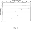
- FIG. 2 reveals that the undercut amount of the optical connector is correlated with the indentation hardness of the abrasive film.
- the indentation hardness of the abrasive film of no greater than 370 N/mm 2 can make the undercut amount of an optical fiber no greater than -10 nm.
- the indentation hardness of the abrasive film of no greater than 370 N/mm 2 is expected to permit stable and accurate control of an undercut of an optical fiber while providing a great grinding force.
- a resin or an elastomer may be used as a principal component of the resin binder 21.
- the resin may be exemplified by an acrylic resin, an epoxy resin, a cellulose resin, a polyvinyl, phenoxy resin, a phenol resin, a polyester, and the like.
- the elastomer may be exemplified by: a thermoplastic elastomer such as a styrene-based elastomer, an olefin-based elastomer, an ester-based elastomer, a urethane-based elastomer, an amide-based elastomer, a polyvinyl chloride (PVC)-based elastomer, and a fluorine-based elastomer; a natural rubber; a styrene-butadiene rubber; an isoprene rubber; a butadiene rubber; a chloroprene rubber; an acrylonitrile-butadiene rubber; a butyl rubber; an ethylene-propylene rubber; an ethylene-propylene-diene rubber; an acrylic rubber; a silicone rubber; and the like.
- a thermoplastic elastomer such as a styrene-based elastomer,
- a resin is used as the principal component
- an acrylic resin, an epoxy resin and polyester which are likely to provide favorable dispersibility of the abrasive particles 22 and favorable adhesiveness to the substrate 10 are preferred.
- an elastomer is used as the principal component, in light of adhesiveness to the substrate 10 and handleability, a urethane-based thermoplastic elastomer, an amide-based thermoplastic elastomer, an acrylonitrile-butadiene rubber, a urethane rubber, and an acrylic rubber are preferred.
- the resin may be at least partially crosslinked, and may contain a curing agent such as polyisocyanate and acrylate.
- the term "principal component" as referred to means a component which is of the highest content, for example a component of which content is no less than 50% by mass.
- the resin binder 21 may contain various types of auxiliary agent, additive and the like ad libitum, such as a resin other than the principal component, a crosslinking agent, a dispersant, a coupling agent, a surfactant, a lubricant, a defoaming agent, a colorant, and the like according to a purpose.
- auxiliary agent additive and the like ad libitum
- a resin other than the principal component such as a crosslinking agent, a dispersant, a coupling agent, a surfactant, a lubricant, a defoaming agent, a colorant, and the like according to a purpose.
- the resin binder 21 in a case in which the principal component of the resin binder 21 is a resin, it is preferred that the resin binder 21 further contains an elastomer.
- the resin binder 21 thus containing an elastomer can lower the indentation hardness of the abrasive layer 20.
- the upper limit of the glass transition temperature of the elastomer is preferably 20 °C and more preferably 15 °C.
- the elastomer may be vitrified during polishing of the optical fiber connector, resulting in hardening of the abrasive layer 20.
- the same ones as the elastomers exemplified for use as the principal component may be used.
- the lower limit of the content of the elastomer with respect to the resin binder 21 is preferably 20% by mass and more preferably 30% by mass.
- the upper limit of the content of the elastomer with respect to the resin binder 21 is preferably 75% by mass and more preferably 50% by mass.
- the content of the elastomer with respect to the resin binder 21 is less than the lower limit, control of the indentation hardness of the abrasive layer 20 may be difficult.
- the content of the elastomer with respect to the resin binder 21 is greater than the upper limit, dispersibility of the abrasive particles 22 in the resin binder 21 may be insufficient.
- the abrasive particles 22 are exemplified by particles of diamond, alumina, silica and the like. Of these, silica particles providing a great grinding force are preferred.
- silica particles for example, particles of well-known silica such as colloidal silica, dry silica, wet silica, fused silica may be used.
- colloidal silica may include organosilica sol in which colloidal silica is dispersed in an organic solvent.
- the abrasive particles 22 include abrasive particles having a primary particle size of no less than 70 nm (large diameter abrasive particles 22a) and abrasive particles having a primary particle size of less than 70 nm (small diameter abrasive particles 22b).
- large diameter abrasive particles 22a included in the abrasive particles 22 the abrasive film has a great grinding force.
- small diameter abrasive particles 22b included in the abrasive particles 22 provides high polishing accuracy.
- the distribution curve of the primary particle size of the abrasive particles 22 preferably has two peaks: in a range of less than 70 nm; and in a range of no less than 70 nm. With such a distribution of the primary particle size, the abrasive film can easily and certainly provide: high polishing accuracy by virtue of the small diameter abrasive particles 22b; and a great grinding force by virtue of the large diameter abrasive particles 22a.
- the lower limit of a minimum value of the primary particle size of the abrasive particles 22 is preferably 1 nm, and more preferably 10 nm.
- the upper limit of a maximum value of the primary particle size of the abrasive particles 22 is preferably 400 nm, and more preferably 300 nm.
- a polishing time period of a connection end face of an optical fiber connector may be increased.
- the maximum value of the primary particle size of the abrasive particles 22 is greater than the upper limit, control of an undercut of an optical fiber during polishing may be difficult.
- the lower limit of the content of the large diameter abrasive particles 22a with respect to the total abrasive particles 22 is 10% by mass and more preferably 25% by mass.
- the upper limit of the content of the large diameter abrasive particles 22a with respect to the total abrasive particles 22 is 50% by mass and more preferably 35% by mass.
- the content of the large diameter abrasive particles 22a with respect to the total abrasive particles 22 is less than the lower limit, the grinding force of the abrasive film may be insufficient.
- the content of the large diameter abrasive particles 22a with respect to the total abrasive particles 22 is greater than the upper limit, control of an undercut amount of an optical fiber during polishing may be difficult.
- the lower limit of the content of the abrasive particles 22 in the abrasive layer 20 is 84% by mass and more preferably 87% by mass.
- the upper limit of the content of the abrasive particles 22 in the abrasive layer 20 is preferably 92% by mass and more preferably 90% by mass.
- the content of the abrasive particles 22 in the abrasive layer 20 is less than the lower limit, the grinding force of the abrasive film may be insufficient.
- the content of the abrasive particles 22 in the abrasive layer 20 is greater than the upper limit, control of the indentation hardness of the abrasive layer 20 may be difficult.
- the production method of the abrasive film includes steps of, for example: preparing a coating liquid; applying the coating liquid onto a surface of the substrate 10; and drying the coating liquid thus applied.
- a solution in which the resin binder 21 and the abrasive particles 22 are dispersed in a solvent is prepared as the coating liquid.
- the solution is not particularly limited as long as the resin binder 21 is soluble therein.
- MEK methyl ethyl ketone
- isophorone isophorone
- terpineol N-methylpyrrolidone
- cyclohexanone propylene carbonate and the like
- a diluent etc. such as water, alcohol, ketone, an acetic acid ester, and an aromatic compound may be added in order to adjust the viscosity and fluidity of the coating liquid.
- various types of auxiliary agent and additive may be mixed therewith.
- the coating liquid prepared in the step of preparing the coating liquid is applied onto a surface of the substrate 10.
- a procedure for the applying is not particularly limited, and a well-known procedure for applying, for example, bar coating, comma coating, spray coating, reverse roll coating, knife coating, screen printing, gravure coating, die coating and the like can be employed.
- the abrasive layer 20 is formed by drying and hardening by a reaction in the coating liquid thus applied. Specifically, for example, hot air of no lower than 90 °C and no higher than 110 °C is applied to the substrate 10 for no less than 20 hrs to evaporate the solvent in the coating liquid while curing a solute, thereby forming the abrasive layer 20.
- the abrasive film can prevent an undercut of an optical fiber after polishing.
- the content of the large diameter abrasive particles 22a with respect to the total abrasive particles is no less than 10% by mass and the content of the abrasive particles 22 in the abrasive layer is no less than 84% by mass, the abrasive film has a great grinding force.
- the present invention is not limited to the aforementioned embodiment, and, in addition to the aforementioned embodiment, can be carried out in various modes with alterations and/or improvements being made.
- a primer-treated layer for ensuring adhesiveness between the substrate and the abrasive layer may be provided between the substrate and the abrasive layer.
- a principal component of the primer-treated layer is not particularly limited as long as adhesiveness between the substrate and the abrasive layer can be ensured, and for example a water soluble or water dispersible polyester or acrylic resin; a resin in which an unsaturated bond-containing compound is grafted to a water soluble or water dispersible hydrophilic group-containing polyester; and the like may be used.
- the primer-treated layer can be formed by, for example, spray-coating a primer agent containing the principal component onto a surface of the substrate and then drying.
- a substrate having a primer-treated layer provided beforehand on a surface thereof may also be used.
- the abrasive layer may have a groove.
- a geometry of the groove may be, for example, an equally spaced grid geometry, or a stripe geometry in which a plurality of linear grooves are arranged in a substantially parallel manner.
- a coating liquid was obtained by mixing: 250 parts by mass of organosilica sol ("MEK-ST” available from Nissan Chemical Industries, Ltd., primary particle size: 10 to 20 nm, solid content: 30% by mass) as the small diameter abrasive particles; 10 parts by mass of fused silica ("UFP-30” available from Denki Kagaku Kogyo K.K., average primary particle size: 99 nm) as the large diameter abrasive particles; 220 parts by mass of a tetrahydrofuran solution containing 5% by mass of a crosslinked urethane-based thermoplastic elastomer (“KURAMIRON U9180” available from Kuraray Co., Ltd.) as the resin binder; 5 parts by mass of polyisocyanate ("Desmodur L75C” available from Sumika Bayer Urethane Co., Ltd., solid content: 75% by mass) as the resin binder; and 33 parts by mass of methyl ethyl ketone as the solvent.
- the coating liquid was applied onto one surface of a polyester film ("Lumirror T91N" available from Toray Industries, Inc., average thickness: 75 ⁇ m) as the substrate by the bar coating procedure, and dried in an oven at 100 °C, whereby an abrasive film having an abrasive layer having an average thickness of 5 ⁇ m was obtained.
- the content of the abrasive particles in the abrasive layer is 85% by mass.
- a coating liquid was obtained by mixing: 207 parts by mass of organosilica sol ("MEK-ST” available from Nissan Chemical Industries, Ltd., primary particle size: 10 to 20 nm, solid content: 30% by mass) as the small diameter abrasive particles; 87 parts by mass of organosilica sol ("IPA-ST-ZL” available from Nissan Chemical Industries, Ltd., primary particle size: 70 to 100 nm, solid content: 30% by mass) as the large diameter abrasive particles; 60 parts by mass of a N,N-dimethylformamide solution containing 5% by mass of a vulcanized acrylonitrile-butadiene rubber ("N230S” available from JSR Co.
- the coating liquid was applied onto one surface of a polyester film ("HLE-75" available from Teij in DuPont Films Japan Limited, average thickness: 75 ⁇ m) as the substrate by the bar coating procedure, and dried in an oven at 100 °C, whereby an abrasive film having an abrasive layer having an average thickness of 6 ⁇ m was obtained.
- the content of the abrasive particles in the abrasive layer is 88% by mass.
- a coating liquid was obtained by mixing: 210 parts by mass of organosilica sol ("MEK-ST” available from Nissan Chemical Industries, Ltd., primary particle size: 10 to 20 nm, solid content: 30% by mass) as the small diameter abrasive particles; 87 parts by mass of organosilica sol ("IPA-ST-ZL” available from Nissan Chemical Industries, Ltd., primary particle size: 70 to 100 nm, solid content: 30% by mass) as the large diameter abrasive particles; 100 parts by mass of a N,N-dimethylformamide solution containing 5% by mass of vulcanized acrylonitrile-butadiene rubber (“N230S” available from JSR Co. Ltd.) as the resin binder; and 7 parts by mass of polyisocyanate ("Desmodur L75C” available from Sumika Bayer Urethane Co., Ltd., solid content: 75% by mass) as the resin binder.
- organosilica sol MEK-ST” available from Nissan Chemical Industries, Ltd., primary particle size:
- the coating liquid was applied onto one surface of a polyester film ("HLE-75" available from Teij in DuPont Films Japan Limited, average thickness: 75 ⁇ m) as the substrate by the bar coating procedure, and dried in an oven at 100 °C, whereby an abrasive film having an abrasive layer having an average thickness of 11 ⁇ m was obtained.
- the content of the abrasive particles in the abrasive layer is 90% by mass.
- a coating liquid was obtained by mixing: 240 parts by mass of organosilica sol ("IPA-ST” available from Nissan Chemical Industries, Ltd., primary particle size: 10 to 20 nm, solid content: 30% by mass) as the small diameter abrasive particles; 18 parts by mass of wet silica ("SP03F” available from Fuso Chemical Co., Ltd, average primary particle size: 300 nm) as the large diameter abrasive particles; 140 parts by mass of a 2-propanol solution containing 5% by mass of a crosslinked acrylic elastomer ("BR102" available from Mitsubishi Rayon Co., Ltd.) as the resin binder; 4 parts by mass of polyisocyanate (“Desmodur L75C” available from Sumika Bayer Urethane Co., Ltd. , solid content: 75% by mass) as the resin binder; and 50 parts by mass of methyl ethyl ketone as the solvent.
- organosilica sol IPA-ST” available from Nissan Chemical Industries, Ltd., primary particle size
- the coating liquid was applied onto one surface of a polyester film ("HLE-75" available from Teij in DuPont Films Japan Limited, average thickness: 75 ⁇ m) as the substrate by the bar coating procedure, and dried in an oven at 100 °C, whereby an abrasive film having an abrasive layer having an average thickness of 5 ⁇ m was obtained.
- the content of the abrasive particles in the abrasive layer is 90% by mass.
- An abrasive film having an abrasive layer having an average thickness of 5 ⁇ m was obtained in a similar manner to Example 1, except that a coating liquid was used in which: the organosilica sol ("MEK-ST” available from Nissan Chemical Industries, Ltd., primary particle size: 10 to 20 nm, solid content: 30% by mass) as the small diameter abrasive particles was in an amount of 175 parts by mass; the fused silica (“UFP-30” available from Denki Kagaku Kogyo K.K., average primary particle size: 99 nm) as the large diameter abrasive particles was in an amount of 7.5 parts by mass; and the resin binder and the solvent were the same as those of Example 1.
- the content of the abrasive particles in the abrasive layer is 80% by mass.
- a coating liquid was obtained by mixing: 267 parts by mass of organosilica sol ("MEK-ST” available from Nissan Chemical Industries, Ltd., primary particle size: 10 to 20 nm, solid content: 30% by mass) as the small diameter abrasive particles; 17 parts by mass of organosilica sol (“IPA-ST-ZL” available from Nissan Chemical Industries, Ltd., primary particle size: 70 to 100 nm, solid content: 30% by mass) as the large diameter abrasive particles; 60 parts by mass of a N,N-dimethylformamide solution containing 5% by mass of an acrylonitrile-butadiene rubber ("N230S” available from JSR Co.
- organosilica sol MEK-ST
- IPA-ST-ZL available from Nissan Chemical Industries, Ltd., primary particle size: 70 to 100 nm, solid content: 30% by mass
- N230S N,N-dimethylformamide solution containing 5% by mass of an acrylonitrile-butadiene rubber
- the resin binder 120 parts by mass of a cellulose resin ("ETHOCEL 100” available from Nisshin Kasei Co. Ltd.) as the resin binder; and 8 parts by mass of polyisocyanate ("Desmodur L75C” available from Sumika Bayer Urethane Co., Ltd., solid content: 75% by mass) as the resin binder.
- ETHOCEL 100 available from Nisshin Kasei Co. Ltd.
- polyisocyanate (“Desmodur L75C” available from Sumika Bayer Urethane Co., Ltd., solid content: 75% by mass
- the coating liquid was applied onto one surface of a polyester film ("HLE-75" available from Teij in DuPont Films Japan Limited, average thickness: 75 ⁇ m) as the substrate by the bar coating procedure, and dried in an oven at 100 °C, whereby an abrasive film having an abrasive layer having an average thickness of 5 ⁇ m was obtained.
- the content of the abrasive particles in the abrasive layer is 85% by mass.
- An abrasive film having an abrasive layer having an average thickness of 5 ⁇ m was obtained in a similar manner to Example 3, except that a coating liquid was used in which: the organosilica sol ("MEK-ST” available from Nissan Chemical Industries, Ltd., primary particle size: 10 to 20 nm, solid content: 30% by mass) as the small diameter abrasive particles was in an amount of 147 parts by mass; the organosilica sol (“IPA-ST-ZL” available from Nissan Chemical Industries, Ltd., primary particle size: 70 to 100 nm, solid content: 30% by mass) as the large diameter abrasive particles was in an amount of 153 parts by mass; and the resin binders were the same as those of Example 3.
- the content of the abrasive particles in the abrasive layer is 90% by mass.
- An abrasive film having an abrasive layer having an average thickness of 6 ⁇ m was obtained in a similar manner to Example 2, except that a coating liquid was used in which: the methyl ethyl ketone containing 5% by mass of a cellulose resin ("ETHOCEL 100" available from Nisshin Kasei Co. Ltd.) was in an amount of 120 parts by mass; the polyisocyanate (“Desmodur L75C" available from Sumika Bayer Urethane Co., Ltd., solid content: 75% by mass) was in amount of 8 parts by mass as the resin binders; and the abrasive particles were the same as those of Example 2. The content of the abrasive particles in the abrasive layer is 88% by mass.
- connection end face of the optical fiber connector having been subjected to intermediate finish polishing, was subjected to final finish polishing for 60 sec at a rotation rate of 1 rpm and a revolution rate of 70 rpm, with ion exchanged water as a polishing liquid.
- the intermediate finish polishing was carried out by: adhesively fixing an abrasive film containing diamond abrasive particles having an average primary particle size of 1 ⁇ m ("TOPXD105” available from Bando Chemical Co. Ltd.) onto an elastic material pad (hardness: 80°) of a polishing machine ("SFP-550S” available from Seikoh Giken Co. Ltd.) ; and polishing a connection end face of the optical fiber connector, having been subjected to rough polishing of a spherical surface, for 120 sec at a rotation rate of 1 rpm and a revolution rate of 70 rpm, with ion exchanged water as a polishing liquid.
- TOPXD105 abrasive film containing diamond abrasive particles having an average primary particle size of 1 ⁇ m
- SFP-550S available from Seikoh Giken Co. Ltd.
- An undercut amount of the polished optical fiber connector was measured by using a 3D fiber optic connector end face geometry measurement apparatus ("ACCIS NC/AC-3000" available from Norland Products, INC.). It is to be noted that in a case in which the optical fiber protrudes with respect to the ferrule, the undercut amount is represented by a negative value. Since a preferred undercut amount is no less than -30 nm and no greater than -10 nm in light of optical loss, measured value was assessed according to the following criteria:
- Comparative Example 3 since the content of the large diameter abrasive particles is greater than 50% by mass, control of the undercut amount of the optical fiber failed. Furthermore, in Comparative Example 4, since the indentation hardness of the abrasive layer is greater than 370 N/mm 2 , the optical fiber is selectively polished during polishing, whereby the undercut amount of the optical fiber is greater than -10 nm.
- the content of the abrasive particles having a primary particle size of no less than 70 nm is no less than 10% by mass and no greater than 50% by mass with respect to the total abrasive particles
- the content of the abrasive particles in the abrasive layer is no less than 84% by mass
- the indentation hardness of the abrasive layer is no greater than 370 N/mm 2 , thereby enabling an undercut of the optical fiber after polishing to be prevented.
- the abrasive film according to the present invention is capable of preventing an undercut of an optical fiber after polishing, while having a great grinding force. Therefore, the abrasive film can be suitably used in, for example, a finishing step of a connection end face of an optical fiber connector.
Landscapes
- Engineering & Computer Science (AREA)
- Mechanical Engineering (AREA)
- Physics & Mathematics (AREA)
- General Physics & Mathematics (AREA)
- Optics & Photonics (AREA)
- Manufacturing & Machinery (AREA)
- Polishing Bodies And Polishing Tools (AREA)
- Grinding And Polishing Of Tertiary Curved Surfaces And Surfaces With Complex Shapes (AREA)
Abstract
Description
- The present invention relates to an abrasive film.
- In optical fiber communication networks, easily detachable connectors are widely used for connection between optical fibers. The connection is provided by butting ferrules, which are used for positioning of the optical fibers, directly against each other. Given this, in order to reduce optical loss (communication loss) from the optical fiber after the connection, a connection end face of the optical fiber connector to be connected is required to have a sufficiently smooth surface and not to generate a gap between optical fibers at the connection end faces (not to have an undercut of the optical fiber with respect to the ferrule).
- Polishing of such a connection end face of an optical fiber is performed in four steps of: removal of an adhesive; rough polishing of a spherical surface; intermediate finishing; and finish polishing. Of these, polishing accuracy of the step of finish polishing largely influences the optical loss. Furthermore, in light of productivity and production cost, an abrasive film used in the step of finish polishing is required to have a great grinding force.
- As such an abrasive film, an abrasive film has been proposed having an abrasive layer containing a resin binder and abrasive particles. In order to meet these needs, attempts have been made such as selection of a type of the resin binder and of the abrasive particles, as well as increase in particle size of the abrasive particles (refer to Japanese Unexamined Patent Application, Publication Nos.
H8-336758 2002-239924 2007-190613 - However, using particles having a larger particle size as the abrasive particles in the abrasive film in order to obtain a great grinding force results in selective polishing of the optical fiber and makes it difficult to prevent an undercut of the optical fiber and to make the optical fiber to protrude from the ferrule, and a gap is more likely to be generated between the optical fibers at the connection end faces. Given this, in the Prior Art, the increased grinding force and prevention of an undercut of an optical fiber are not sufficiently concomitantly provided.
-
- Patent Document 1: Japanese Unexamined Patent Application, Publication No.
H8-336758 - Patent Document 2: Japanese Unexamined Patent Application, Publication No.
2002-239924 - Patent Document 3: Japanese Unexamined Patent Application, Publication No.
2007-190613 - The present invention has been made in view of the aforementioned situation, and an object of the invention is to provide an abrasive film that is capable of preventing an undercut of an optical fiber after polishing, while providing a great grinding force.
- As a result of a thorough investigation, the present inventors have obtained a knowledge that an undercut of an optical fiber can be inhibited by controlling an indentation hardness of the abrasive layer and the content of abrasive particles having a large primary particle size. Accordingly, the present inventors have found that an abrasive film can be obtained that is capable of preventing an undercut of an optical fiber while employing the abrasive particles having a large primary particle size, leading to completion of the present invention.
- More specifically, the present invention was made for solving the aforementioned problems, and according to an aspect of the present invention, an abrasive film includes a substrate and an abrasive layer that is overlaid on a top face side thereof, the abrasive layer including a resin binder and abrasive particles dispersed in the resin binder; the content of the abrasive particles having a primary particle size of no less than 70 nm being no less than 10% by mass and no greater than 50% by mass with respect to the total abrasive particles; the content of the abrasive particles in the abrasive layer being no less than 84% by mass; and the indentation hardness of the abrasive layer being no greater than 370 N/mm2.
- Since the indentation hardness of the abrasive layer is no greater than the above-defined upper limit and the content of abrasive particles having a primary particle size of no less than 70 nm with respect to the total abrasive particles is no greater than the above-defined upper limit, the abrasive film is capable of inhibiting an undercut of an optical fiber after polishing. In addition, since the indentation hardness of the abrasive layer is no less than the above-defined lower limit and the content of abrasive particles having a primary particle size of no less than 70 nm with respect to the total abrasive particles is no less than the above-defined lower limit, the abrasive film has a great grinding force.
- The abrasive particles are preferably silica particles. Since silica particles are abrasive particles that are suitable for use in a final finishing step in which a low surface roughness is required for a connection end face of the optical fiber connector, employing silica particles having a large primary particle size enables a great grinding force to be provided while maintaining polishing accuracy.
- An average thickness of the abrasive layer is preferably no less than 4 µm and no greater than 15 µm. By thus defining the average thickness of the abrasive layer to fall within the above-defined range, a low level of the indentation hardness of the abrasive layer can be maintained, an undercut of an optical fiber can further easily be prevented, and wear resistance of the abrasive layer can be improved.
- The resin binder preferably contains an elastomer having a glass transition temperature of no greater than 20 °C, and the content of the elastomer in the resin binder is preferably no less than 20% by mass. By thus defining the content of the elastomer having a glass transition temperature of no greater than 20 °C in the resin binder to be no less than the above-defined lower limit, the indentation hardness of the abrasive layer can be easily controlled.
- The term "indentation hardness" as referred to means a value obtained in accordance with ISO-14577-1. In addition, the term "primary particle" as referred to means a particle that may be considered as a unit particle from a geometric configuration thereof, the term "primary particle size" as referred to means a diameter of a particle measured by using an image of the particle observed by way of a scanning electron microscope (SEM) or a transmission electron microscope (TEM), and "diameter of a particle" as referred to means a diameter of a minimum circle circumscribed to an image of the particle.
- As explained in the foregoing, the abrasive film according to the present invention can prevent an undercut of an optical fiber after polishing, while providing a great grinding force. Therefore, the abrasive film can be suitably used in, for example, a finishing step of a connection end face of an optical fiber connector.
-
-
FIG. 1 is a schematic end view of an abrasive film according to an embodiment of the present invention; and -
FIG. 2 shows a graph indicating a relationship between an indentation hardness of an abrasive film, and an undercut amount of a polished optical fiber connector. - Embodiments of the present invention will be described in detail hereinafter with reference to the drawings as necessary.
- The abrasive film illustrated in
FIG. 1 includes a sheet-shaped substrate 10 and anadhesive layer 20 that is overlaid on a top face thereof. - Although a material for the substrate is not particularly limited, a material that has appropriate rigidity and ensures favorable adhesiveness and cohesiveness to the
abrasive layer 20 is preferred. As such a material, a well-known thermoplastic resin may be employed that is exemplified by an acrylic resin, polycarbonate, polyethylene terephthalate (PET), polypropylene (PP), polyethylene (PE), and the like. As thesubstrate 10, a biaxially stretched film of PET, PP, PE, or the like may also be employed. Furthermore, a surface of thesubstrate 10 may be subjected to a treatment for increasing adhesiveness such as a chemical treatment, corona treatment, primer treatment and the like. - Although a planar shape and a size of the
substrate 10 are not particularly limited, the planar shape and the size may be, for example, a square shape of 127 mm x 127 mm and a circular shape of 127 mm in diameter. Alternatively, a configuration in which a plurality ofsubstrates 10 aligned on a planar surface are supported by a single support may also be employed. - Although an average thickness of the
substrate 10 is not particularly limited, the average thickness may be, for example, no less than 30 µm and no greater than 150 µm. When the average thickness of thesubstrate 10 is less than the above-defined lower limit, strength and flatness of the abrasive film may be insufficient. On the other hand, when the average thickness of thesubstrate 10 is greater than the above-defined upper limit, the abrasive film may be unnecessarily thick and thus difficult to handle. - The
abrasive layer 20 is overlaid on a surface of thesubstrate 10 and contains aresin binder 21 andabrasive particles 22 dispersed in theresin binder 21. - The lower limit of the average thickness of the
abrasive layer 20 is preferably 4 µm, and more preferably 5 µm. In addition, the upper limit of the average thickness of theabrasive layer 20 is preferably 15 µm, and more preferably 12 µm. When the average thickness of theabrasive layer 20 is less than the lower limit, abrasion resistance of the abrasive film may be insufficient. On the other hand, when the average thickness of theabrasive layer 20 is greater than the upper limit, control of an undercut amount of an optical fiber during polishing may be difficult. - The upper limit of the indentation hardness of the
abrasive layer 20 is 370 N/mm2 and more preferably 350 N/mm2. In addition, the lower limit of the indentation hardness of theabrasive layer 20 is preferably 250 N/mm2 and more preferably 280 N/mm2. When the indentation hardness of theabrasive layer 20 is greater than the upper limit, an optical fiber may be selectively polished during polishing, resulting in an undercut of the optical fiber with respect to a ferrule. On the other hand, when the indentation hardness of theabrasive layer 20 is less than the lower limit, the grinding force of the abrasive film may be insufficient. - An influence of the indentation hardness of the
abrasive layer 20 on an undercut of an optical fiber will now be discussed. Polishing of a connection end face of an optical fiber connector is performed by pressing the connection end face of the optical fiber connector against the abrasive film adhered to an elastic material pad while applying a load. In a case in which the indentation hardness of theabrasive layer 20 is high, it is expected that polishing pressure is high in the vicinity of a vertex of the optical fiber connector that has been spherically formed, whereby the optical fiber in the vicinity of the vertex of the optical fiber connector is selectively polished, and thus an undercut of the optical fiber with respect to a ferrule would occur. Given this, by lowering the indentation hardness of theabrasive layer 20, followability of theabrasive layer 20 to the elastic material pad is expected to increase, and therefore, stable and accurate control of an undercut of the optical fiber is expected to be realized. - On the basis of the above discussion, the present inventors conducted the following test to determine an optimum range of the indentation hardness of the
abrasive layer 20 permitting stable and accurate control of an undercut of an optical fiber while maintaining a great grinding force. First, as an abrasive film having a great grinding force, five types of abrasive films were provided in which the content of theabrasive particles 22 having a primary particle size of no less than 70 nm was no less than 10% by mass and no greater than 50% by mass with respect to the totalabrasive particles 22, and the content of theabrasive particles 22 in theabrasive layer 20 was no less than 84% by mass. The indentation hardness of these abrasive films was measured by using a nano-indentation hardness tester ("ENT-1100a" available from Elionix Inc.). Next, the abrasive film was punched to give a circular shape of 127 mm in diameter and adhesively fixed onto an elastic material pad (hardness: 70°) of a polishing machine ("SFP-550S" available from Seikoh Giken Co. Ltd.). A connection end face of an optical fiber connector, having been subjected to intermediate finish polishing, was subjected to final finish polishing for 60 sec at a rotation rate of 1 rpm and a revolution rate of 70 rpm, with ion exchanged water as a polishing liquid. Thereafter, an undercut amount of the optical fiber connector thus polished was measured by using a 3D fiber optic connector end face geometry measurement apparatus ("ACCIS NC/AC-3000" (Automated Non-Contact Interferometer System), available from Norland Products, INC.). It is to be noted that in a case in which the optical fiber protrudes with respect to the ferrule, the undercut amount is represented by a negative value. - Based on the results of the measurement, a relationship was obtained between the indentation hardness of the abrasive film and the undercut amount of the optical fiber connector having been polished. The results are shown in
FIG. 2. FIG. 2 reveals that the undercut amount of the optical connector is correlated with the indentation hardness of the abrasive film. In addition, the indentation hardness of the abrasive film of no greater than 370 N/mm2 can make the undercut amount of an optical fiber no greater than -10 nm. Since a preferred undercut amount in light of the optical loss is no less than -30 nm and no greater than -10 nm, the indentation hardness of the abrasive film of no greater than 370 N/mm2 is expected to permit stable and accurate control of an undercut of an optical fiber while providing a great grinding force. - A resin or an elastomer may be used as a principal component of the
resin binder 21. The resin may be exemplified by an acrylic resin, an epoxy resin, a cellulose resin, a polyvinyl, phenoxy resin, a phenol resin, a polyester, and the like. The elastomer may be exemplified by: a thermoplastic elastomer such as a styrene-based elastomer, an olefin-based elastomer, an ester-based elastomer, a urethane-based elastomer, an amide-based elastomer, a polyvinyl chloride (PVC)-based elastomer, and a fluorine-based elastomer; a natural rubber; a styrene-butadiene rubber; an isoprene rubber; a butadiene rubber; a chloroprene rubber; an acrylonitrile-butadiene rubber; a butyl rubber; an ethylene-propylene rubber; an ethylene-propylene-diene rubber; an acrylic rubber; a silicone rubber; and the like. In a case in which a resin is used as the principal component, an acrylic resin, an epoxy resin and polyester, which are likely to provide favorable dispersibility of theabrasive particles 22 and favorable adhesiveness to thesubstrate 10, are preferred. In a case in which an elastomer is used as the principal component, in light of adhesiveness to thesubstrate 10 and handleability, a urethane-based thermoplastic elastomer, an amide-based thermoplastic elastomer, an acrylonitrile-butadiene rubber, a urethane rubber, and an acrylic rubber are preferred. Furthermore, the resin may be at least partially crosslinked, and may contain a curing agent such as polyisocyanate and acrylate. The term "principal component" as referred to means a component which is of the highest content, for example a component of which content is no less than 50% by mass. - The
resin binder 21 may contain various types of auxiliary agent, additive and the like ad libitum, such as a resin other than the principal component, a crosslinking agent, a dispersant, a coupling agent, a surfactant, a lubricant, a defoaming agent, a colorant, and the like according to a purpose. - In addition, in a case in which the principal component of the
resin binder 21 is a resin, it is preferred that theresin binder 21 further contains an elastomer. Theresin binder 21 thus containing an elastomer can lower the indentation hardness of theabrasive layer 20. - In a case in which the
resin binder 21 contains an elastomer, the upper limit of the glass transition temperature of the elastomer is preferably 20 °C and more preferably 15 °C. When the glass transition temperature of the elastomer is greater than the upper limit, the elastomer may be vitrified during polishing of the optical fiber connector, resulting in hardening of theabrasive layer 20. - As the elastomer, the same ones as the elastomers exemplified for use as the principal component may be used.
- The lower limit of the content of the elastomer with respect to the
resin binder 21 is preferably 20% by mass and more preferably 30% by mass. Whereas, the upper limit of the content of the elastomer with respect to theresin binder 21 is preferably 75% by mass and more preferably 50% by mass. When the content of the elastomer with respect to theresin binder 21 is less than the lower limit, control of the indentation hardness of theabrasive layer 20 may be difficult. On the other hand, when the content of the elastomer with respect to theresin binder 21 is greater than the upper limit, dispersibility of theabrasive particles 22 in theresin binder 21 may be insufficient. - The
abrasive particles 22 are exemplified by particles of diamond, alumina, silica and the like. Of these, silica particles providing a great grinding force are preferred. As the silica particles, for example, particles of well-known silica such as colloidal silica, dry silica, wet silica, fused silica may be used. As used herein, "colloidal silica" may include organosilica sol in which colloidal silica is dispersed in an organic solvent. - The
abrasive particles 22 include abrasive particles having a primary particle size of no less than 70 nm (large diameterabrasive particles 22a) and abrasive particles having a primary particle size of less than 70 nm (small diameterabrasive particles 22b). By virtue of the large diameterabrasive particles 22a included in theabrasive particles 22, the abrasive film has a great grinding force. In addition, by virtue of the small diameterabrasive particles 22b included in theabrasive particles 22, the abrasive film provides high polishing accuracy. - The distribution curve of the primary particle size of the
abrasive particles 22 preferably has two peaks: in a range of less than 70 nm; and in a range of no less than 70 nm. With such a distribution of the primary particle size, the abrasive film can easily and certainly provide: high polishing accuracy by virtue of the small diameterabrasive particles 22b; and a great grinding force by virtue of the large diameterabrasive particles 22a. - The lower limit of a minimum value of the primary particle size of the
abrasive particles 22 is preferably 1 nm, and more preferably 10 nm. Meanwhile, the upper limit of a maximum value of the primary particle size of theabrasive particles 22 is preferably 400 nm, and more preferably 300 nm. When the minimum value of the primary particle size of theabrasive particles 22 is less than the lower limit, a polishing time period of a connection end face of an optical fiber connector may be increased. On the other hand, when the maximum value of the primary particle size of theabrasive particles 22 is greater than the upper limit, control of an undercut of an optical fiber during polishing may be difficult. - The lower limit of the content of the large diameter
abrasive particles 22a with respect to the totalabrasive particles 22 is 10% by mass and more preferably 25% by mass. Whereas, the upper limit of the content of the large diameterabrasive particles 22a with respect to the totalabrasive particles 22 is 50% by mass and more preferably 35% by mass. When the content of the large diameterabrasive particles 22a with respect to the totalabrasive particles 22 is less than the lower limit, the grinding force of the abrasive film may be insufficient. On the other hand, when the content of the large diameterabrasive particles 22a with respect to the totalabrasive particles 22 is greater than the upper limit, control of an undercut amount of an optical fiber during polishing may be difficult. - The lower limit of the content of the
abrasive particles 22 in theabrasive layer 20 is 84% by mass and more preferably 87% by mass. Whereas, the upper limit of the content of theabrasive particles 22 in theabrasive layer 20 is preferably 92% by mass and more preferably 90% by mass. When the content of theabrasive particles 22 in theabrasive layer 20 is less than the lower limit, the grinding force of the abrasive film may be insufficient. On the other hand, when the content of theabrasive particles 22 in theabrasive layer 20 is greater than the upper limit, control of the indentation hardness of theabrasive layer 20 may be difficult. - As the production method of the abrasive film, a well-known technique for production of a thin film can be employed that can secure sufficient adhesiveness and cohesiveness between the
substrate 10 and theadhesive layer 20. The production method of the abrasive film includes steps of, for example: preparing a coating liquid; applying the coating liquid onto a surface of thesubstrate 10; and drying the coating liquid thus applied. - First, in the step of preparing a coating liquid, a solution in which the
resin binder 21 and theabrasive particles 22 are dispersed in a solvent is prepared as the coating liquid. The solution is not particularly limited as long as theresin binder 21 is soluble therein. Specifically, methyl ethyl ketone (MEK), isophorone, terpineol, N-methylpyrrolidone, cyclohexanone, propylene carbonate and the like may be used. A diluent etc. such as water, alcohol, ketone, an acetic acid ester, and an aromatic compound may be added in order to adjust the viscosity and fluidity of the coating liquid. In addition, various types of auxiliary agent and additive may be mixed therewith. - Next, in the step of applying the coating liquid, the coating liquid prepared in the step of preparing the coating liquid is applied onto a surface of the
substrate 10. A procedure for the applying is not particularly limited, and a well-known procedure for applying, for example, bar coating, comma coating, spray coating, reverse roll coating, knife coating, screen printing, gravure coating, die coating and the like can be employed. - Subsequently, in the step of drying, the
abrasive layer 20 is formed by drying and hardening by a reaction in the coating liquid thus applied. Specifically, for example, hot air of no lower than 90 °C and no higher than 110 °C is applied to thesubstrate 10 for no less than 20 hrs to evaporate the solvent in the coating liquid while curing a solute, thereby forming theabrasive layer 20. - Since the indentation hardness of the
abrasive layer 20 is no greater than 370 N/mm2 and the content of large diameterabrasive particles 22a having a primary particle size of no less than 70 nm with respect to the totalabrasive particles 22 is no greater than 50% by mass, the abrasive film can prevent an undercut of an optical fiber after polishing. In addition, since the content of the large diameterabrasive particles 22a with respect to the total abrasive particles is no less than 10% by mass and the content of theabrasive particles 22 in the abrasive layer is no less than 84% by mass, the abrasive film has a great grinding force. - The present invention is not limited to the aforementioned embodiment, and, in addition to the aforementioned embodiment, can be carried out in various modes with alterations and/or improvements being made.
- Although in the aforementioned embodiment, the abrasive film in which the abrasive layer is formed directly on a surface of the substrate has been described, a primer-treated layer for ensuring adhesiveness between the substrate and the abrasive layer may be provided between the substrate and the abrasive layer. A principal component of the primer-treated layer is not particularly limited as long as adhesiveness between the substrate and the abrasive layer can be ensured, and for example a water soluble or water dispersible polyester or acrylic resin; a resin in which an unsaturated bond-containing compound is grafted to a water soluble or water dispersible hydrophilic group-containing polyester; and the like may be used.
- The primer-treated layer can be formed by, for example, spray-coating a primer agent containing the principal component onto a surface of the substrate and then drying. Alternatively, a substrate having a primer-treated layer provided beforehand on a surface thereof may also be used.
- In addition, the abrasive layer may have a groove. A geometry of the groove may be, for example, an equally spaced grid geometry, or a stripe geometry in which a plurality of linear grooves are arranged in a substantially parallel manner. When the abrasive layer has a groove, polishing waste etc. generated during polishing can be efficiently removed.
- Hereinafter, the present invention will be explained in more detail by way of Examples and Comparative Examples, but the present invention is not limited to the following Examples.
- A coating liquid was obtained by mixing: 250 parts by mass of organosilica sol ("MEK-ST" available from Nissan Chemical Industries, Ltd., primary particle size: 10 to 20 nm, solid content: 30% by mass) as the small diameter abrasive particles; 10 parts by mass of fused silica ("UFP-30" available from Denki Kagaku Kogyo K.K., average primary particle size: 99 nm) as the large diameter abrasive particles; 220 parts by mass of a tetrahydrofuran solution containing 5% by mass of a crosslinked urethane-based thermoplastic elastomer ("KURAMIRON U9180" available from Kuraray Co., Ltd.) as the resin binder; 5 parts by mass of polyisocyanate ("Desmodur L75C" available from Sumika Bayer Urethane Co., Ltd., solid content: 75% by mass) as the resin binder; and 33 parts by mass of methyl ethyl ketone as the solvent.
- The coating liquid was applied onto one surface of a polyester film ("Lumirror T91N" available from Toray Industries, Inc., average thickness: 75 µm) as the substrate by the bar coating procedure, and dried in an oven at 100 °C, whereby an abrasive film having an abrasive layer having an average thickness of 5 µm was obtained. The content of the abrasive particles in the abrasive layer is 85% by mass.
- A coating liquid was obtained by mixing: 207 parts by mass of organosilica sol ("MEK-ST" available from Nissan Chemical Industries, Ltd., primary particle size: 10 to 20 nm, solid content: 30% by mass) as the small diameter abrasive particles; 87 parts by mass of organosilica sol ("IPA-ST-ZL" available from Nissan Chemical Industries, Ltd., primary particle size: 70 to 100 nm, solid content: 30% by mass) as the large diameter abrasive particles; 60 parts by mass of a N,N-dimethylformamide solution containing 5% by mass of a vulcanized acrylonitrile-butadiene rubber ("N230S" available from JSR Co. Ltd.) as the resin binder; 60 parts by mass of methyl ethyl ketone containing 5% by mass of a cellulose resin ("ETHOCEL 100" available from Nisshin Kasei Co. Ltd.) as the resin binder; and 7 parts by mass of polyisocyanate ("Desmodur L75C" available from Sumika Bayer Urethane Co., Ltd., solid content: 75% by mass) as the resin binder.
- The coating liquid was applied onto one surface of a polyester film ("HLE-75" available from Teij in DuPont Films Japan Limited, average thickness: 75 µm) as the substrate by the bar coating procedure, and dried in an oven at 100 °C, whereby an abrasive film having an abrasive layer having an average thickness of 6 µm was obtained. The content of the abrasive particles in the abrasive layer is 88% by mass.
- A coating liquid was obtained by mixing: 210 parts by mass of organosilica sol ("MEK-ST" available from Nissan Chemical Industries, Ltd., primary particle size: 10 to 20 nm, solid content: 30% by mass) as the small diameter abrasive particles; 87 parts by mass of organosilica sol ("IPA-ST-ZL" available from Nissan Chemical Industries, Ltd., primary particle size: 70 to 100 nm, solid content: 30% by mass) as the large diameter abrasive particles; 100 parts by mass of a N,N-dimethylformamide solution containing 5% by mass of vulcanized acrylonitrile-butadiene rubber ("N230S" available from JSR Co. Ltd.) as the resin binder; and 7 parts by mass of polyisocyanate ("Desmodur L75C" available from Sumika Bayer Urethane Co., Ltd., solid content: 75% by mass) as the resin binder.
- The coating liquid was applied onto one surface of a polyester film ("HLE-75" available from Teij in DuPont Films Japan Limited, average thickness: 75 µm) as the substrate by the bar coating procedure, and dried in an oven at 100 °C, whereby an abrasive film having an abrasive layer having an average thickness of 11 µm was obtained. The content of the abrasive particles in the abrasive layer is 90% by mass.
- A coating liquid was obtained by mixing: 240 parts by mass of organosilica sol ("IPA-ST" available from Nissan Chemical Industries, Ltd., primary particle size: 10 to 20 nm, solid content: 30% by mass) as the small diameter abrasive particles; 18 parts by mass of wet silica ("SP03F" available from Fuso Chemical Co., Ltd, average primary particle size: 300 nm) as the large diameter abrasive particles; 140 parts by mass of a 2-propanol solution containing 5% by mass of a crosslinked acrylic elastomer ("BR102" available from Mitsubishi Rayon Co., Ltd.) as the resin binder; 4 parts by mass of polyisocyanate ("Desmodur L75C" available from Sumika Bayer Urethane Co., Ltd. , solid content: 75% by mass) as the resin binder; and 50 parts by mass of methyl ethyl ketone as the solvent.
- The coating liquid was applied onto one surface of a polyester film ("HLE-75" available from Teij in DuPont Films Japan Limited, average thickness: 75 µm) as the substrate by the bar coating procedure, and dried in an oven at 100 °C, whereby an abrasive film having an abrasive layer having an average thickness of 5 µm was obtained. The content of the abrasive particles in the abrasive layer is 90% by mass.
- An abrasive film having an abrasive layer having an average thickness of 5 µm was obtained in a similar manner to Example 1, except that a coating liquid was used in which: the organosilica sol ("MEK-ST" available from Nissan Chemical Industries, Ltd., primary particle size: 10 to 20 nm, solid content: 30% by mass) as the small diameter abrasive particles was in an amount of 175 parts by mass; the fused silica ("UFP-30" available from Denki Kagaku Kogyo K.K., average primary particle size: 99 nm) as the large diameter abrasive particles was in an amount of 7.5 parts by mass; and the resin binder and the solvent were the same as those of Example 1. The content of the abrasive particles in the abrasive layer is 80% by mass.
- A coating liquid was obtained by mixing: 267 parts by mass of organosilica sol ("MEK-ST" available from Nissan Chemical Industries, Ltd., primary particle size: 10 to 20 nm, solid content: 30% by mass) as the small diameter abrasive particles; 17 parts by mass of organosilica sol ("IPA-ST-ZL" available from Nissan Chemical Industries, Ltd., primary particle size: 70 to 100 nm, solid content: 30% by mass) as the large diameter abrasive particles; 60 parts by mass of a N,N-dimethylformamide solution containing 5% by mass of an acrylonitrile-butadiene rubber ("N230S" available from JSR Co. Ltd.) as the resin binder; 120 parts by mass of a cellulose resin ("ETHOCEL 100" available from Nisshin Kasei Co. Ltd.) as the resin binder; and 8 parts by mass of polyisocyanate ("Desmodur L75C" available from Sumika Bayer Urethane Co., Ltd., solid content: 75% by mass) as the resin binder.
- The coating liquid was applied onto one surface of a polyester film ("HLE-75" available from Teij in DuPont Films Japan Limited, average thickness: 75 µm) as the substrate by the bar coating procedure, and dried in an oven at 100 °C, whereby an abrasive film having an abrasive layer having an average thickness of 5 µm was obtained. The content of the abrasive particles in the abrasive layer is 85% by mass.
- An abrasive film having an abrasive layer having an average thickness of 5 µm was obtained in a similar manner to Example 3, except that a coating liquid was used in which: the organosilica sol ("MEK-ST" available from Nissan Chemical Industries, Ltd., primary particle size: 10 to 20 nm, solid content: 30% by mass) as the small diameter abrasive particles was in an amount of 147 parts by mass; the organosilica sol ("IPA-ST-ZL" available from Nissan Chemical Industries, Ltd., primary particle size: 70 to 100 nm, solid content: 30% by mass) as the large diameter abrasive particles was in an amount of 153 parts by mass; and the resin binders were the same as those of Example 3. The content of the abrasive particles in the abrasive layer is 90% by mass.
- An abrasive film having an abrasive layer having an average thickness of 6 µm was obtained in a similar manner to Example 2, except that a coating liquid was used in which: the methyl ethyl ketone containing 5% by mass of a cellulose resin ("ETHOCEL 100" available from Nisshin Kasei Co. Ltd.) was in an amount of 120 parts by mass; the polyisocyanate ("Desmodur L75C" available from Sumika Bayer Urethane Co., Ltd., solid content: 75% by mass) was in amount of 8 parts by mass as the resin binders; and the abrasive particles were the same as those of Example 2. The content of the abrasive particles in the abrasive layer is 88% by mass.
- By using the above-described abrasive films obtained in Examples 1 to 4 and Comparative Examples 1 to 4, an optical fiber connector in which an optical fiber is adhered to a ferrule ("SC ferrule" available from Seikoh Giken Co. Ltd.) was polished. First, the abrasive film was punched to give a circular shape of 127 mm in diameter and adhesively fixed onto an elastic material pad (hardness: 70°) of a polishing machine ("SFP-550S" available from Seikoh Giken Co. Ltd.). A connection end face of the optical fiber connector, having been subjected to intermediate finish polishing, was subjected to final finish polishing for 60 sec at a rotation rate of 1 rpm and a revolution rate of 70 rpm, with ion exchanged water as a polishing liquid.
- It is to be noted that the intermediate finish polishing was carried out by: adhesively fixing an abrasive film containing diamond abrasive particles having an average primary particle size of 1 µm ("TOPXD105" available from Bando Chemical Co. Ltd.) onto an elastic material pad (hardness: 80°) of a polishing machine ("SFP-550S" available from Seikoh Giken Co. Ltd.) ; and polishing a connection end face of the optical fiber connector, having been subjected to rough polishing of a spherical surface, for 120 sec at a rotation rate of 1 rpm and a revolution rate of 70 rpm, with ion exchanged water as a polishing liquid.
- The following evaluations were conducted for the polished optical fiber connectors. The results are shown in Table 1.
- An undercut amount of the polished optical fiber connector was measured by using a 3D fiber optic connector end face geometry measurement apparatus ("ACCIS NC/AC-3000" available from Norland Products, INC.). It is to be noted that in a case in which the optical fiber protrudes with respect to the ferrule, the undercut amount is represented by a negative value. Since a preferred undercut amount is no less than -30 nm and no greater than -10 nm in light of optical loss, measured value was assessed according to the following criteria:
- A: undercut amount falling within the range of no less than -30 nm and no greater than -10 nm; and
- B: undercut amount being out of the range of no less than -30 nm and no greater than -10 nm.
- An end face state was observed by using "Video Fiber Microscope" available from Westover Scientific, Inc., and assessed according to the following criteria:
- A: adhered matter and scratch not being observed and favorable end face obtained; and
- B: adhered matter and scratch being observed and favorable end face not being obtained.
- In Table 1, "-" indicates that the measurement was not conducted.
- The results shown in Table 1 reveal that, with the abrasive films of Examples 1 to 4, compared with the abrasive films of Comparative Examples 1 to 4, the undercut amount of the optical fiber connector is controlled to fall within the range of no less than -30 nm and no greater than -10 nm, and the end face state is favorable. On the other hand, in Comparative Example 1, since the content of the abrasive particles is less than 84% by mass, the grinding force is supposed to be insufficient, leading to a failure to obtain a favorable end face. In Comparative Example 2, since the content of the large diameter abrasive particles is less than 10% by mass, the grinding force is supposed to be insufficient, leading to a failure to obtain a favorable end face. In addition, in Comparative Example 3, since the content of the large diameter abrasive particles is greater than 50% by mass, control of the undercut amount of the optical fiber failed. Furthermore, in Comparative Example 4, since the indentation hardness of the abrasive layer is greater than 370 N/mm2, the optical fiber is selectively polished during polishing, whereby the undercut amount of the optical fiber is greater than -10 nm. In other words, in the abrasive films of Examples 1 to 4, the content of the abrasive particles having a primary particle size of no less than 70 nm is no less than 10% by mass and no greater than 50% by mass with respect to the total abrasive particles, the content of the abrasive particles in the abrasive layer is no less than 84% by mass, and the indentation hardness of the abrasive layer is no greater than 370 N/mm2, thereby enabling an undercut of the optical fiber after polishing to be prevented.
- The abrasive film according to the present invention is capable of preventing an undercut of an optical fiber after polishing, while having a great grinding force. Therefore, the abrasive film can be suitably used in, for example, a finishing step of a connection end face of an optical fiber connector.
-
- 10
- Substrate
- 20
- Abrasive layer
- 21
- Resin binder
- 22
- Abrasive particle
- 22a
- Large diameter abrasive particle
- 22b
- Small diameter abrasive particle
| Example 1 | Example 2 | Example 3 | Example 4 | Comparative Example 1 | Comparative Example 2 | Comparative Example 3 | Comparative Example 4 | ||
| Proportion in Abrasive Layer (mass %) | Abrasive particles | 85 | 88 | 90 | 90 | 80 | 85 | 90 | 88 |
| (Small Diameter Abrasive particles) | (75) | (62) | (63) | (72) | (70) | (80) | (44) | (62) | |
| (Large Diameter Abrasive particles) | (10) | (26) | (27) | (18) | (10) | (5) | (46) | (26) | |
| Resin Binder | 15 | 12 | 10 | 10 | 20 | 15 | 10 | 12 | |
| (Elastomer) | (11) | (3) | (5) | (7) | (15) | (3) | (5) | (0) | |
| (Other than Elastomer) | (4) | (9) | (5) | (3) | (5) | (12) | (5) | (12) | |
| Proportion in Abrasive particles (mass %) | Large Diameter Abrasive particles | 12 | 30 | 30 | 20 | 13 | 6 | 51 | 30 |
| Proportion in Resin Binder (mass %) | Elastomer | 73 | 25 | 50 | 70 | 75 | 20 | 50 | 0 |
| Abrasive Layer | Average Thickness (µm) | 5 | 6 | 11 | 5 | 5 | 5 | 5 | 6 |
| Indentation Hardness (N/mm2) | 296 | 313 | 326 | 345 | 290 | 304 | 318 | 380 | |
| Result of Polishing of Optical Fiber Connector | Undercut Amount(mm) | -25 | -14 | -21 | -12 | - | - | +10 | -9 |
| Assessment of Undercut Amount | A | A | A | A | - | - | B | B | |
| End Face State | A | A | A | A | B | B | A | A | |
Claims (4)
- An abrasive film comprising a substrate and an abrasive layer that is overlaid on a top face side thereof,
wherein:the abrasive layer comprises a resin binder, and abrasive particles dispersed in the resin binder;a content of the abrasive particles having a primary particle size of no less than 70 nm is no less than 10% by mass and no greater than 50% by mass with respect to total abrasive particles;a content of the abrasive particles in the abrasive layer is no less than 84% by mass; andan indentation hardness of the abrasive layer is no greater than 370 N/mm2. - The abrasive film according to claim 1, wherein the abrasive particles are silica particles.
- The abrasive film according to claim 1, wherein an average thickness of the abrasive layer is no less than 4 µm and no greater than 15 µm.
- The abrasive film according to claim 1, wherein:the resin binder comprises an elastomer having a glass transition temperature of no greater than 20 °C; anda content of the elastomer with respect to the resin binder is no less than 20% by mass.
Applications Claiming Priority (2)
| Application Number | Priority Date | Filing Date | Title |
|---|---|---|---|
| JP2014140073 | 2014-07-07 | ||
| PCT/JP2015/068488 WO2016006476A1 (en) | 2014-07-07 | 2015-06-26 | Polishing film |
Publications (3)
| Publication Number | Publication Date |
|---|---|
| EP3168002A1 true EP3168002A1 (en) | 2017-05-17 |
| EP3168002A4 EP3168002A4 (en) | 2018-08-22 |
| EP3168002B1 EP3168002B1 (en) | 2022-03-23 |
Family
ID=55064114
Family Applications (1)
| Application Number | Title | Priority Date | Filing Date |
|---|---|---|---|
| EP15819449.8A Active EP3168002B1 (en) | 2014-07-07 | 2015-06-26 | Polishing film |
Country Status (6)
| Country | Link |
|---|---|
| US (1) | US10543582B2 (en) |
| EP (1) | EP3168002B1 (en) |
| JP (1) | JP5921790B1 (en) |
| KR (1) | KR101904732B1 (en) |
| CN (1) | CN106470800B (en) |
| WO (1) | WO2016006476A1 (en) |
Families Citing this family (6)
| Publication number | Priority date | Publication date | Assignee | Title |
|---|---|---|---|---|
| CN107053028B (en) * | 2017-03-02 | 2024-05-07 | 深圳市摩码科技有限公司 | A grinding belt |
| TWI669193B (en) * | 2017-08-28 | 2019-08-21 | 中國砂輪企業股份有限公司 | Grinding tool and method of manufacturing same |
| TWI645940B (en) * | 2018-01-15 | 2019-01-01 | 中國砂輪企業股份有限公司 | Grinding tool |
| TWI645939B (en) * | 2018-01-15 | 2019-01-01 | 中國砂輪企業股份有限公司 | Grinding tool |
| CN111015535B (en) * | 2019-12-04 | 2021-04-23 | 东莞金太阳研磨股份有限公司 | Precise polishing film with special structure and preparation method thereof |
| WO2022220161A1 (en) * | 2021-04-15 | 2022-10-20 | 株式会社アドマテックス | Ferrule polishing material |
Family Cites Families (29)
| Publication number | Priority date | Publication date | Assignee | Title |
|---|---|---|---|---|
| US3505045A (en) * | 1968-03-19 | 1970-04-07 | Minnesota Mining & Mfg | Abrasive backings saturated with copolymers of acrylic ester and nitrile monomers |
| JPS6234762A (en) | 1985-08-07 | 1987-02-14 | Furukawa Electric Co Ltd:The | Polishing machine for convex endface of optical connector core |
| JPH0319775A (en) * | 1989-06-12 | 1991-01-28 | Hitachi Maxell Ltd | Abrasive sheet |
| US5667842A (en) * | 1993-10-27 | 1997-09-16 | Minnesota Mining And Manufacturing Company | Abrasive articles incorporating addition polymerizable resins and reactive diluents, and methods of making said abrasive articles |
| JP3305557B2 (en) | 1995-04-10 | 2002-07-22 | 大日本印刷株式会社 | Polishing tape, method for producing the same, and coating agent for the polishing tape |
| JP3769589B2 (en) | 2001-02-21 | 2006-04-26 | 日本ミクロコーティング株式会社 | Polishing film and method for producing the same |
| WO2002092286A1 (en) * | 2001-05-14 | 2002-11-21 | Nihon Micro Coating Co., Ltd. | Abrasive film and method of producing the same |
| JP2003260648A (en) * | 2002-03-06 | 2003-09-16 | Fuji Photo Film Co Ltd | End surface polishing method of optical fiber ferrule |
| US20030171078A1 (en) | 2002-03-06 | 2003-09-11 | Fuji Photo Film Co., Ltd. | Polishing member and method for polishing end faces of optical fibers |
| US20040063391A1 (en) * | 2002-08-26 | 2004-04-01 | Jsr Corporation | Composition for polishing pad and polishing pad therewith |
| US6858292B2 (en) * | 2002-09-06 | 2005-02-22 | 3M Innovative Properties Company | Abrasive articles with resin control additives |
| JP2004249370A (en) | 2003-02-18 | 2004-09-09 | Hitachi Maxell Ltd | Polishing body and method for manufacturing polishing body |
| JP2007190613A (en) | 2004-02-09 | 2007-08-02 | Bando Chem Ind Ltd | Polishing film and method for producing the same |
| JP2011507570A (en) * | 2007-12-19 | 2011-03-10 | インバテック テクノロジー センター ゲーエムベーハー | Modular stent assembly |
| US20090266002A1 (en) * | 2008-04-29 | 2009-10-29 | Rajeev Bajaj | Polishing pad and method of use |
| KR20130038958A (en) * | 2008-07-22 | 2013-04-18 | 생-고벵 아브라시프 | Coated abrasive products containing aggregates |
| US20100107509A1 (en) * | 2008-11-04 | 2010-05-06 | Guiselin Olivier L | Coated abrasive article for polishing or lapping applications and system and method for producing the same. |
| CN102245351A (en) * | 2008-12-22 | 2011-11-16 | 圣戈班磨料磨具有限公司 | Rigid or flexible, macro-porous abrasive article |
| WO2010123744A2 (en) * | 2009-04-23 | 2010-10-28 | Cabot Microelectronics Corporation | Cmp porous pad with particles in a polymeric matrix |
| JP2010274348A (en) | 2009-05-27 | 2010-12-09 | Nihon Micro Coating Co Ltd | Polishing film and polishing method using the same |
| WO2012092619A2 (en) * | 2010-12-30 | 2012-07-05 | Saint-Gobain Abrasives, Inc. | Coated abrasive aggregates and products containg same |
| WO2012092618A2 (en) * | 2010-12-30 | 2012-07-05 | Saint-Gobain Abrasives, Inc. | Imide cross-linked binders for abrasive articles |
| JP5851124B2 (en) * | 2011-06-13 | 2016-02-03 | スリーエム イノベイティブ プロパティズ カンパニー | Polishing structure |
| WO2013049526A2 (en) * | 2011-09-29 | 2013-04-04 | Saint-Gobain Abrasives, Inc. | Abrasive products and methods for finishing hard surfaces |
| WO2013094052A1 (en) * | 2011-12-22 | 2013-06-27 | 三洋電機株式会社 | Solar cell and solar cell module |
| CH708019B1 (en) * | 2012-03-16 | 2015-09-15 | Saint Gobain Abrasives Inc | Abrasive products for surface finishing. |
| WO2013149197A1 (en) * | 2012-03-30 | 2013-10-03 | Saint-Gobain Abrasives, Inc. | Abrasive products and methods for fine polishing of ophthalmic lenses |
| WO2015112540A1 (en) * | 2014-01-24 | 2015-07-30 | 3M Innovative Properties Company | Abrasive material having a structured surface |
| US20160000292A1 (en) * | 2014-07-02 | 2016-01-07 | The Procter & Gamble Company | Nonwoven articles comprising abrasive particles |
-
2015
- 2015-06-26 JP JP2015556320A patent/JP5921790B1/en active Active
- 2015-06-26 CN CN201580036615.2A patent/CN106470800B/en active Active
- 2015-06-26 US US15/324,073 patent/US10543582B2/en active Active
- 2015-06-26 EP EP15819449.8A patent/EP3168002B1/en active Active
- 2015-06-26 KR KR1020177000240A patent/KR101904732B1/en active Active
- 2015-06-26 WO PCT/JP2015/068488 patent/WO2016006476A1/en not_active Ceased
Also Published As
| Publication number | Publication date |
|---|---|
| EP3168002B1 (en) | 2022-03-23 |
| KR20170016443A (en) | 2017-02-13 |
| WO2016006476A1 (en) | 2016-01-14 |
| EP3168002A4 (en) | 2018-08-22 |
| JPWO2016006476A1 (en) | 2017-04-27 |
| KR101904732B1 (en) | 2018-10-05 |
| CN106470800A (en) | 2017-03-01 |
| CN106470800B (en) | 2019-06-18 |
| US20170157745A1 (en) | 2017-06-08 |
| US10543582B2 (en) | 2020-01-28 |
| JP5921790B1 (en) | 2016-05-24 |
Similar Documents
| Publication | Publication Date | Title |
|---|---|---|
| EP3168002B1 (en) | Polishing film | |
| EP3184244B1 (en) | Abrasive film | |
| JP6644932B1 (en) | Optical film and manufacturing method thereof, polarizing plate, and image display device | |
| US10451816B2 (en) | Polishing sheet equipped with nano-silica polishing particles, and polishing method and manufacturing method for optical fiber connector using polishing sheet | |
| JP2009072832A (en) | Polishing sheet and method for producing the same | |
| KR20240015703A (en) | Surface-protective film and optical component attached with the same | |
| KR101968924B1 (en) | Release film for antistatic surface-protective film | |
| JP3924252B2 (en) | Polishing film and method for producing the same | |
| KR102182243B1 (en) | Surface-protective film and optical component attached with the same | |
| EP1707312A1 (en) | Polishing method and polishing film used in such polishing method | |
| JP2003291068A (en) | Polishing medium for end face of optical fiber | |
| WO2020022269A1 (en) | Optical film, production method thereof, polarizer, and image display device | |
| US20030121213A1 (en) | Lapping medium and method of generating the same | |
| JP2002233964A (en) | Polishing medium and its manufacturing method | |
| CN115247035A (en) | Surface protection film and optical component bonded with the surface protection film | |
| CN118725764A (en) | Surface protection films and optical components | |
| JP2002233961A (en) | Polishing medium and its manufacturing method | |
| JP2002254319A (en) | Polishing medium for optical fiber end surface |
Legal Events
| Date | Code | Title | Description |
|---|---|---|---|
| STAA | Information on the status of an ep patent application or granted ep patent |
Free format text: STATUS: THE INTERNATIONAL PUBLICATION HAS BEEN MADE |
|
| PUAI | Public reference made under article 153(3) epc to a published international application that has entered the european phase |
Free format text: ORIGINAL CODE: 0009012 |
|
| STAA | Information on the status of an ep patent application or granted ep patent |
Free format text: STATUS: REQUEST FOR EXAMINATION WAS MADE |
|
| 17P | Request for examination filed |
Effective date: 20170117 |
|
| AK | Designated contracting states |
Kind code of ref document: A1 Designated state(s): AL AT BE BG CH CY CZ DE DK EE ES FI FR GB GR HR HU IE IS IT LI LT LU LV MC MK MT NL NO PL PT RO RS SE SI SK SM TR |
|
| AX | Request for extension of the european patent |
Extension state: BA ME |
|
| DAV | Request for validation of the european patent (deleted) | ||
| DAX | Request for extension of the european patent (deleted) | ||
| A4 | Supplementary search report drawn up and despatched |
Effective date: 20180724 |
|
| RIC1 | Information provided on ipc code assigned before grant |
Ipc: B24B 19/00 20060101ALI20180718BHEP Ipc: B24D 11/00 20060101AFI20180718BHEP Ipc: B24D 3/28 20060101ALI20180718BHEP Ipc: G02B 6/25 20060101ALI20180718BHEP |
|
| GRAP | Despatch of communication of intention to grant a patent |
Free format text: ORIGINAL CODE: EPIDOSNIGR1 |
|
| STAA | Information on the status of an ep patent application or granted ep patent |
Free format text: STATUS: GRANT OF PATENT IS INTENDED |
|
| INTG | Intention to grant announced |
Effective date: 20211201 |
|
| GRAS | Grant fee paid |
Free format text: ORIGINAL CODE: EPIDOSNIGR3 |
|
| GRAA | (expected) grant |
Free format text: ORIGINAL CODE: 0009210 |
|
| STAA | Information on the status of an ep patent application or granted ep patent |
Free format text: STATUS: THE PATENT HAS BEEN GRANTED |
|
| AK | Designated contracting states |
Kind code of ref document: B1 Designated state(s): AL AT BE BG CH CY CZ DE DK EE ES FI FR GB GR HR HU IE IS IT LI LT LU LV MC MK MT NL NO PL PT RO RS SE SI SK SM TR |
|
| REG | Reference to a national code |
Ref country code: GB Ref legal event code: FG4D |
|
| REG | Reference to a national code |
Ref country code: CH Ref legal event code: EP |
|
| REG | Reference to a national code |
Ref country code: IE Ref legal event code: FG4D |
|
| REG | Reference to a national code |
Ref country code: DE Ref legal event code: R096 Ref document number: 602015077749 Country of ref document: DE |
|
| REG | Reference to a national code |
Ref country code: AT Ref legal event code: REF Ref document number: 1477121 Country of ref document: AT Kind code of ref document: T Effective date: 20220415 |
|
| REG | Reference to a national code |
Ref country code: LT Ref legal event code: MG9D |
|
| REG | Reference to a national code |
Ref country code: NL Ref legal event code: MP Effective date: 20220323 |
|
| PG25 | Lapsed in a contracting state [announced via postgrant information from national office to epo] |
Ref country code: SE Free format text: LAPSE BECAUSE OF FAILURE TO SUBMIT A TRANSLATION OF THE DESCRIPTION OR TO PAY THE FEE WITHIN THE PRESCRIBED TIME-LIMIT Effective date: 20220323 Ref country code: RS Free format text: LAPSE BECAUSE OF FAILURE TO SUBMIT A TRANSLATION OF THE DESCRIPTION OR TO PAY THE FEE WITHIN THE PRESCRIBED TIME-LIMIT Effective date: 20220323 Ref country code: NO Free format text: LAPSE BECAUSE OF FAILURE TO SUBMIT A TRANSLATION OF THE DESCRIPTION OR TO PAY THE FEE WITHIN THE PRESCRIBED TIME-LIMIT Effective date: 20220623 Ref country code: LT Free format text: LAPSE BECAUSE OF FAILURE TO SUBMIT A TRANSLATION OF THE DESCRIPTION OR TO PAY THE FEE WITHIN THE PRESCRIBED TIME-LIMIT Effective date: 20220323 Ref country code: HR Free format text: LAPSE BECAUSE OF FAILURE TO SUBMIT A TRANSLATION OF THE DESCRIPTION OR TO PAY THE FEE WITHIN THE PRESCRIBED TIME-LIMIT Effective date: 20220323 Ref country code: BG Free format text: LAPSE BECAUSE OF FAILURE TO SUBMIT A TRANSLATION OF THE DESCRIPTION OR TO PAY THE FEE WITHIN THE PRESCRIBED TIME-LIMIT Effective date: 20220623 |
|
| REG | Reference to a national code |
Ref country code: AT Ref legal event code: MK05 Ref document number: 1477121 Country of ref document: AT Kind code of ref document: T Effective date: 20220323 |
|
| PG25 | Lapsed in a contracting state [announced via postgrant information from national office to epo] |
Ref country code: LV Free format text: LAPSE BECAUSE OF FAILURE TO SUBMIT A TRANSLATION OF THE DESCRIPTION OR TO PAY THE FEE WITHIN THE PRESCRIBED TIME-LIMIT Effective date: 20220323 Ref country code: GR Free format text: LAPSE BECAUSE OF FAILURE TO SUBMIT A TRANSLATION OF THE DESCRIPTION OR TO PAY THE FEE WITHIN THE PRESCRIBED TIME-LIMIT Effective date: 20220624 Ref country code: FI Free format text: LAPSE BECAUSE OF FAILURE TO SUBMIT A TRANSLATION OF THE DESCRIPTION OR TO PAY THE FEE WITHIN THE PRESCRIBED TIME-LIMIT Effective date: 20220323 |
|
| PG25 | Lapsed in a contracting state [announced via postgrant information from national office to epo] |
Ref country code: NL Free format text: LAPSE BECAUSE OF FAILURE TO SUBMIT A TRANSLATION OF THE DESCRIPTION OR TO PAY THE FEE WITHIN THE PRESCRIBED TIME-LIMIT Effective date: 20220323 |
|
| PG25 | Lapsed in a contracting state [announced via postgrant information from national office to epo] |
Ref country code: SM Free format text: LAPSE BECAUSE OF FAILURE TO SUBMIT A TRANSLATION OF THE DESCRIPTION OR TO PAY THE FEE WITHIN THE PRESCRIBED TIME-LIMIT Effective date: 20220323 Ref country code: SK Free format text: LAPSE BECAUSE OF FAILURE TO SUBMIT A TRANSLATION OF THE DESCRIPTION OR TO PAY THE FEE WITHIN THE PRESCRIBED TIME-LIMIT Effective date: 20220323 Ref country code: RO Free format text: LAPSE BECAUSE OF FAILURE TO SUBMIT A TRANSLATION OF THE DESCRIPTION OR TO PAY THE FEE WITHIN THE PRESCRIBED TIME-LIMIT Effective date: 20220323 Ref country code: PT Free format text: LAPSE BECAUSE OF FAILURE TO SUBMIT A TRANSLATION OF THE DESCRIPTION OR TO PAY THE FEE WITHIN THE PRESCRIBED TIME-LIMIT Effective date: 20220725 Ref country code: ES Free format text: LAPSE BECAUSE OF FAILURE TO SUBMIT A TRANSLATION OF THE DESCRIPTION OR TO PAY THE FEE WITHIN THE PRESCRIBED TIME-LIMIT Effective date: 20220323 Ref country code: EE Free format text: LAPSE BECAUSE OF FAILURE TO SUBMIT A TRANSLATION OF THE DESCRIPTION OR TO PAY THE FEE WITHIN THE PRESCRIBED TIME-LIMIT Effective date: 20220323 Ref country code: CZ Free format text: LAPSE BECAUSE OF FAILURE TO SUBMIT A TRANSLATION OF THE DESCRIPTION OR TO PAY THE FEE WITHIN THE PRESCRIBED TIME-LIMIT Effective date: 20220323 Ref country code: AT Free format text: LAPSE BECAUSE OF FAILURE TO SUBMIT A TRANSLATION OF THE DESCRIPTION OR TO PAY THE FEE WITHIN THE PRESCRIBED TIME-LIMIT Effective date: 20220323 |
|
| PG25 | Lapsed in a contracting state [announced via postgrant information from national office to epo] |
Ref country code: PL Free format text: LAPSE BECAUSE OF FAILURE TO SUBMIT A TRANSLATION OF THE DESCRIPTION OR TO PAY THE FEE WITHIN THE PRESCRIBED TIME-LIMIT Effective date: 20220323 Ref country code: IS Free format text: LAPSE BECAUSE OF FAILURE TO SUBMIT A TRANSLATION OF THE DESCRIPTION OR TO PAY THE FEE WITHIN THE PRESCRIBED TIME-LIMIT Effective date: 20220723 Ref country code: AL Free format text: LAPSE BECAUSE OF FAILURE TO SUBMIT A TRANSLATION OF THE DESCRIPTION OR TO PAY THE FEE WITHIN THE PRESCRIBED TIME-LIMIT Effective date: 20220323 |
|
| REG | Reference to a national code |
Ref country code: DE Ref legal event code: R097 Ref document number: 602015077749 Country of ref document: DE |
|
| PLBE | No opposition filed within time limit |
Free format text: ORIGINAL CODE: 0009261 |
|
| STAA | Information on the status of an ep patent application or granted ep patent |
Free format text: STATUS: NO OPPOSITION FILED WITHIN TIME LIMIT |
|
| PG25 | Lapsed in a contracting state [announced via postgrant information from national office to epo] |
Ref country code: MC Free format text: LAPSE BECAUSE OF FAILURE TO SUBMIT A TRANSLATION OF THE DESCRIPTION OR TO PAY THE FEE WITHIN THE PRESCRIBED TIME-LIMIT Effective date: 20220323 Ref country code: DK Free format text: LAPSE BECAUSE OF FAILURE TO SUBMIT A TRANSLATION OF THE DESCRIPTION OR TO PAY THE FEE WITHIN THE PRESCRIBED TIME-LIMIT Effective date: 20220323 |
|
| REG | Reference to a national code |
Ref country code: CH Ref legal event code: PL |
|
| REG | Reference to a national code |
Ref country code: BE Ref legal event code: MM Effective date: 20220630 |
|
| 26N | No opposition filed |
Effective date: 20230102 |
|
| GBPC | Gb: european patent ceased through non-payment of renewal fee |
Effective date: 20220626 |
|
| PG25 | Lapsed in a contracting state [announced via postgrant information from national office to epo] |
Ref country code: LU Free format text: LAPSE BECAUSE OF NON-PAYMENT OF DUE FEES Effective date: 20220626 Ref country code: LI Free format text: LAPSE BECAUSE OF NON-PAYMENT OF DUE FEES Effective date: 20220630 Ref country code: IE Free format text: LAPSE BECAUSE OF NON-PAYMENT OF DUE FEES Effective date: 20220626 Ref country code: FR Free format text: LAPSE BECAUSE OF NON-PAYMENT OF DUE FEES Effective date: 20220630 Ref country code: CH Free format text: LAPSE BECAUSE OF NON-PAYMENT OF DUE FEES Effective date: 20220630 |
|
| PG25 | Lapsed in a contracting state [announced via postgrant information from national office to epo] |
Ref country code: SI Free format text: LAPSE BECAUSE OF FAILURE TO SUBMIT A TRANSLATION OF THE DESCRIPTION OR TO PAY THE FEE WITHIN THE PRESCRIBED TIME-LIMIT Effective date: 20220323 Ref country code: GB Free format text: LAPSE BECAUSE OF NON-PAYMENT OF DUE FEES Effective date: 20220626 Ref country code: BE Free format text: LAPSE BECAUSE OF NON-PAYMENT OF DUE FEES Effective date: 20220630 |
|
| PG25 | Lapsed in a contracting state [announced via postgrant information from national office to epo] |
Ref country code: IT Free format text: LAPSE BECAUSE OF FAILURE TO SUBMIT A TRANSLATION OF THE DESCRIPTION OR TO PAY THE FEE WITHIN THE PRESCRIBED TIME-LIMIT Effective date: 20220323 |
|
| PG25 | Lapsed in a contracting state [announced via postgrant information from national office to epo] |
Ref country code: HU Free format text: LAPSE BECAUSE OF FAILURE TO SUBMIT A TRANSLATION OF THE DESCRIPTION OR TO PAY THE FEE WITHIN THE PRESCRIBED TIME-LIMIT; INVALID AB INITIO Effective date: 20150626 |
|
| PG25 | Lapsed in a contracting state [announced via postgrant information from national office to epo] |
Ref country code: MK Free format text: LAPSE BECAUSE OF FAILURE TO SUBMIT A TRANSLATION OF THE DESCRIPTION OR TO PAY THE FEE WITHIN THE PRESCRIBED TIME-LIMIT Effective date: 20220323 Ref country code: CY Free format text: LAPSE BECAUSE OF FAILURE TO SUBMIT A TRANSLATION OF THE DESCRIPTION OR TO PAY THE FEE WITHIN THE PRESCRIBED TIME-LIMIT Effective date: 20220323 |
|
| PG25 | Lapsed in a contracting state [announced via postgrant information from national office to epo] |
Ref country code: MT Free format text: LAPSE BECAUSE OF FAILURE TO SUBMIT A TRANSLATION OF THE DESCRIPTION OR TO PAY THE FEE WITHIN THE PRESCRIBED TIME-LIMIT Effective date: 20220323 |
|
| PGFP | Annual fee paid to national office [announced via postgrant information from national office to epo] |
Ref country code: DE Payment date: 20250429 Year of fee payment: 11 |
|
| PG25 | Lapsed in a contracting state [announced via postgrant information from national office to epo] |
Ref country code: TR Free format text: LAPSE BECAUSE OF FAILURE TO SUBMIT A TRANSLATION OF THE DESCRIPTION OR TO PAY THE FEE WITHIN THE PRESCRIBED TIME-LIMIT Effective date: 20220323 |