EP3167760A1 - Mounting mechanism - Google Patents
Mounting mechanism Download PDFInfo
- Publication number
- EP3167760A1 EP3167760A1 EP16194105.9A EP16194105A EP3167760A1 EP 3167760 A1 EP3167760 A1 EP 3167760A1 EP 16194105 A EP16194105 A EP 16194105A EP 3167760 A1 EP3167760 A1 EP 3167760A1
- Authority
- EP
- European Patent Office
- Prior art keywords
- component
- mounting mechanism
- base
- movable member
- linking
- Prior art date
- Legal status (The legal status is an assumption and is not a legal conclusion. Google has not performed a legal analysis and makes no representation as to the accuracy of the status listed.)
- Granted
Links
- 230000007246 mechanism Effects 0.000 title claims abstract description 79
- 230000005540 biological transmission Effects 0.000 claims abstract description 74
- 230000004044 response Effects 0.000 claims abstract description 15
- 238000006073 displacement reaction Methods 0.000 claims description 2
- 230000008093 supporting effect Effects 0.000 description 8
- 230000000712 assembly Effects 0.000 description 4
- 238000000429 assembly Methods 0.000 description 4
- 238000003825 pressing Methods 0.000 description 4
- 230000009471 action Effects 0.000 description 1
- 238000004026 adhesive bonding Methods 0.000 description 1
- 230000003993 interaction Effects 0.000 description 1
- 238000000034 method Methods 0.000 description 1
- 230000008569 process Effects 0.000 description 1
Images


Classifications
-
- A—HUMAN NECESSITIES
- A47—FURNITURE; DOMESTIC ARTICLES OR APPLIANCES; COFFEE MILLS; SPICE MILLS; SUCTION CLEANERS IN GENERAL
- A47B—TABLES; DESKS; OFFICE FURNITURE; CABINETS; DRAWERS; GENERAL DETAILS OF FURNITURE
- A47B88/00—Drawers for tables, cabinets or like furniture; Guides for drawers
- A47B88/90—Constructional details of drawers
- A47B88/944—Drawers characterised by the front panel
- A47B88/95—Drawers characterised by the front panel characterised by connection means for the front panel
-
- A—HUMAN NECESSITIES
- A47—FURNITURE; DOMESTIC ARTICLES OR APPLIANCES; COFFEE MILLS; SPICE MILLS; SUCTION CLEANERS IN GENERAL
- A47B—TABLES; DESKS; OFFICE FURNITURE; CABINETS; DRAWERS; GENERAL DETAILS OF FURNITURE
- A47B88/00—Drawers for tables, cabinets or like furniture; Guides for drawers
- A47B88/40—Sliding drawers; Slides or guides therefor
- A47B88/483—Sliding drawers; Slides or guides therefor with single extensible guides or parts
-
- A—HUMAN NECESSITIES
- A47—FURNITURE; DOMESTIC ARTICLES OR APPLIANCES; COFFEE MILLS; SPICE MILLS; SUCTION CLEANERS IN GENERAL
- A47B—TABLES; DESKS; OFFICE FURNITURE; CABINETS; DRAWERS; GENERAL DETAILS OF FURNITURE
- A47B88/00—Drawers for tables, cabinets or like furniture; Guides for drawers
- A47B88/90—Constructional details of drawers
- A47B88/944—Drawers characterised by the front panel
- A47B88/95—Drawers characterised by the front panel characterised by connection means for the front panel
- A47B88/956—Drawers characterised by the front panel characterised by connection means for the front panel for enabling adjustment of the front panel
-
- A—HUMAN NECESSITIES
- A47—FURNITURE; DOMESTIC ARTICLES OR APPLIANCES; COFFEE MILLS; SPICE MILLS; SUCTION CLEANERS IN GENERAL
- A47B—TABLES; DESKS; OFFICE FURNITURE; CABINETS; DRAWERS; GENERAL DETAILS OF FURNITURE
- A47B88/00—Drawers for tables, cabinets or like furniture; Guides for drawers
- A47B88/90—Constructional details of drawers
- A47B88/944—Drawers characterised by the front panel
- A47B88/95—Drawers characterised by the front panel characterised by connection means for the front panel
- A47B2088/951—Drawers characterised by the front panel characterised by connection means for the front panel having male and female interlocking parts
-
- A—HUMAN NECESSITIES
- A47—FURNITURE; DOMESTIC ARTICLES OR APPLIANCES; COFFEE MILLS; SPICE MILLS; SUCTION CLEANERS IN GENERAL
- A47B—TABLES; DESKS; OFFICE FURNITURE; CABINETS; DRAWERS; GENERAL DETAILS OF FURNITURE
- A47B88/00—Drawers for tables, cabinets or like furniture; Guides for drawers
- A47B88/90—Constructional details of drawers
- A47B88/944—Drawers characterised by the front panel
- A47B88/95—Drawers characterised by the front panel characterised by connection means for the front panel
- A47B2088/952—Drawers characterised by the front panel characterised by connection means for the front panel having two parts and using a screw
-
- A—HUMAN NECESSITIES
- A47—FURNITURE; DOMESTIC ARTICLES OR APPLIANCES; COFFEE MILLS; SPICE MILLS; SUCTION CLEANERS IN GENERAL
- A47B—TABLES; DESKS; OFFICE FURNITURE; CABINETS; DRAWERS; GENERAL DETAILS OF FURNITURE
- A47B88/00—Drawers for tables, cabinets or like furniture; Guides for drawers
- A47B88/90—Constructional details of drawers
- A47B88/944—Drawers characterised by the front panel
- A47B88/95—Drawers characterised by the front panel characterised by connection means for the front panel
- A47B2088/953—Drawers characterised by the front panel characterised by connection means for the front panel fastening the front panel to a metal sheet side wall
-
- A—HUMAN NECESSITIES
- A47—FURNITURE; DOMESTIC ARTICLES OR APPLIANCES; COFFEE MILLS; SPICE MILLS; SUCTION CLEANERS IN GENERAL
- A47B—TABLES; DESKS; OFFICE FURNITURE; CABINETS; DRAWERS; GENERAL DETAILS OF FURNITURE
- A47B88/00—Drawers for tables, cabinets or like furniture; Guides for drawers
- A47B88/90—Constructional details of drawers
- A47B88/944—Drawers characterised by the front panel
- A47B88/95—Drawers characterised by the front panel characterised by connection means for the front panel
- A47B2088/954—Drawers characterised by the front panel characterised by connection means for the front panel fastening the front panel by a sprung bolt, latch or lock-bolt
-
- A—HUMAN NECESSITIES
- A47—FURNITURE; DOMESTIC ARTICLES OR APPLIANCES; COFFEE MILLS; SPICE MILLS; SUCTION CLEANERS IN GENERAL
- A47B—TABLES; DESKS; OFFICE FURNITURE; CABINETS; DRAWERS; GENERAL DETAILS OF FURNITURE
- A47B88/00—Drawers for tables, cabinets or like furniture; Guides for drawers
- A47B88/90—Constructional details of drawers
- A47B88/944—Drawers characterised by the front panel
- A47B88/95—Drawers characterised by the front panel characterised by connection means for the front panel
- A47B2088/955—Drawers characterised by the front panel characterised by connection means for the front panel fastening the front panel using a toggle-lever
Definitions
- the present invention relates to a mounting mechanism and more particularly to one that is adapted for use with furniture components and configured to mount at least one first component to a second component in a detachable manner.
- a drawer or cabinet includes a plurality of sidewalls and panels. These sidewalls and panels define a storage space therebetween.
- the sidewalls and panels e.g., a front panel
- US Patent Nos. 8,297,724 B2 and 8,727,461 B2 and US Patent Publication Nos. 2014/0070687 A1 , 2014/0072366 A1 , 2014/0077677 A1 , and 2014/0252936 A1 disclose a drawer sidewall or lateral frame member to which the front panel of a drawer can be mounted releasably.
- the front panel and sidewalls of a drawer may have problem being securely assembled together if the errors of assembly exceed the tolerable range.
- the present invention relates to a mounting mechanism for detachably mounting at least one first component to a second component without using tools.
- a mounting mechanism adapted for mounting at least one first component to a second component includes a base, a transmission device, and a movable member.
- the base is mountable on the second component.
- the transmission device is arranged at the base.
- the movable member is movably connected to the transmission device and is configured to be displaced with respect to the base from a first position to a second position in response to displacement between the at least one first component and the second component in a predetermined direction, thereby mounting the at least one first component to the second component.
- a mounting mechanism adapted for mounting at least one first component to a second component includes a base, a movable member, and a transmission device.
- the base is mounted on the second component.
- the movable member is movably mounted on the base and includes a holding portion to which the at least one first component can be mounted.
- the transmission device is configured to displace the movable member from a first position to a second position in response to the at least one first component being mounted to the holding portion of the movable member.
- a mounting mechanism is adapted for use in a system which includes a main body and an object mounted to the main body via a slide rail assembly.
- the slide rail assembly includes a first rail and a second rail displaceable with respect to the first rail.
- the object includes a sidewall and a panel.
- the sidewall is arranged at the second rail.
- the panel is mounted to a second component of the sidewall via at least one first component.
- the mounting mechanism includes a base, a movable member, a transmission device, a first linking member, and a second linking member.
- the base is mounted on the second component.
- the movable member is mounted on the base and includes a rack.
- the transmission device is configured to displace the movable member from a first position to a second position in response to the at least one first component being mounted to the movable member.
- the transmission device includes a first transmission member with a plurality of first teeth and a second transmission member with a plurality of second teeth. The first teeth of the first transmission member mesh with the rack of the movable member.
- the first linking member is pivotally connected to the base and includes a plurality of teeth meshing with the second teeth of the second transmission member.
- the second linking member is connected to the first linking member.
- the second linking member is connected to a connecting rod, and there is an elastic member mounted on the connecting rod and configured to apply an elastic force to the movable member.
- the transmission device includes a first transmission member with a plurality of first teeth
- the movable member includes a rack meshing with the first teeth of the first transmission member
- the mounting mechanism further includes a connecting rod and an elastic member.
- the connecting rod is mounted on the base.
- the elastic member is mounted on the connecting rod and is configured to apply an elastic force to the movable member.
- the mounting mechanism further includes an extension wall connected to the base and having a mounting feature
- the connecting rod has a head and a body connected to the head.
- the body is movably connected to the mounting feature while the elastic member is pressed between the extension wall and the head.
- the transmission device further includes a second transmission member with a plurality of second teeth
- the mounting mechanism further includes a first linking member and a second linking member.
- the first liking member is pivotally connected to the base and includes a plurality of teeth meshing with the second teeth of the second transmission member.
- the second linking member is movably connected between the first linking member and the head of the connecting rod.
- the second linking member further includes a manual operation portion with which to adjust the second linking member manually in order to bring the movable member from the second position to the first position with respect to the base.
- the mounting mechanism further includes a stop wall adjacent to the second linking member.
- the stop wall stops the second linking member in response to an external force applied to the at least one first component in the opposite direction of the predetermined direction.
- the mounting mechanism further includes a stopping feature arranged at the base.
- the stopping feature arranged at the base.
- the movable member includes a guiding portion
- the mounting mechanism further includes a protruding member.
- the guiding portion has a first channel and a second channel, wherein the second channel is in communication with and is tilted by an angle with respect to the first channel.
- the protruding member selectively extends through a corresponding one of the first channel and the second channel. When the protruding member corresponds to the second channel, the movable member is at the first position with respect to the base.
- the movable member further includes a holding portion, and the at least one first component has an auxiliary portion.
- the holding portion includes an engaging section and a guiding surface adjacent to the engaging section.
- the auxiliary portion is configured to push the guiding surface of the movable member and be engageably mounted to the engaging section.
- the at least one first component includes two corresponding longitudinal walls and an auxiliary portion connected between the two longitudinal walls, one of the two longitudinal walls of the at least one first component has a post, and the auxiliary portion can be mounted to the movable member.
- a first adjusting member is arranged at the at least one first component and includes an adjusting portion, a pushing portion, and a threaded feature.
- the threaded feature is connected between the adjusting portion and the pushing portion and can be threadedly connected to the post.
- the pushing portion corresponds to the base.
- the at least one first component can be displaced in a transverse direction according to adjustment of the first adjusting member.
- the base includes a first hole and a second hole
- the mounting mechanism further includes a guiding member and a second adjusting member.
- the shape of the second hole is substantially perpendicular to the shape of the first hole.
- the guiding member has a connecting portion and a stop connected to the connecting portion.
- the connecting portion extends through the first hole and is connected to the second component such that the stop is stopped on one side of the base.
- the second adjusting member corresponds to the second hole of the base and includes an adjusting portion, a pivotal connection portion, and an eccentric portion connected between the adjusting portion and the pivotal connection portion of the second adjusting member.
- the adjusting portion and the pivotal connection portion have a common axis.
- the pivotal connection portion is pivotally connected to the second component.
- the eccentric portion is eccentric with respect to the axis and is configured to push the base in order to displace the base according to the shape of the first hole.
- the at least one first component is a first furniture component
- the second component is a second furniture component
- the movable member is connected to the transmission device in a meshing manner.
- the movable member includes two holding portions to which two first components can be respectively and engageably mounted.
- each of the holding portions includes an engaging section and a guiding surface adjacent to the engaging section, and each of the two first components has an auxiliary portion for pushing a corresponding one of the guiding surfaces of the movable member and to be engageably mounted to a corresponding one of the engaging sections.
- the movable member includes two guiding portions
- the mounting mechanism further includes a protruding member and a rod member.
- Each of the guiding portions has a first channel and a second channel.
- the second channel is in communication with and is tilted by an angle with respect to the first channel.
- the protruding member and the rod member extend through the two guiding portions respectively.
- the movable member is at the first position with respect to the base.
- the mounting mechanism further includes a driving device mounted on the second component and having a pushing member.
- the two first components drive the driving device when displaced in the predetermined direction; as a result, the movable member is displaced from the first position toward the second position in response to the pushing action of the pushing member of the driving device.
- the driving device further includes a driving member. Both the driving member and the pushing member are pivotally connected to the second component.
- the pushing member is movably connected to the driving member.
- the driving member is configured to be driven by the two first components in order to drive the pushing member.
- the transmission device can displace the movable member from the first position to the second position and thereby mount the first component, which is mounted on the movable member, to the second component.
- the system 20 in an embodiment of the present invention includes a main body 22 and at least one object 24 to be carried by the main body 22 (hereinafter referred to as the object 24).
- the system 20 may be a furniture-related system or cabinet-related system.
- the system 20 includes two objects 24, which are implemented as drawers by way of example.
- the following description refers to only one of the two objects 24.
- a pair of slide rail assemblies 26 are mounted between the main body 22 and the object 24.
- the slide rail assemblies 26 in this embodiment are undermount drawer slides, and each slide rail assembly 26 is mounted adjacent to a lateral bottom portion of the object 24. This arrangement allows the object 24 to be pulled out of and pushed back into the main body 22 with ease.
- the slide rail assembly 26 includes a first rail 28 and a second rail 30 which can be longitudinally displaced with respect to the first rail 28.
- the slide rail assembly 26 further includes a third rail 32 arranged between the first rail 28 and the second rail 30 to increase the distance by which the second rail 30 can be displaced with respect to the first rail 28.
- the object 24 at least includes a sidewall 34 arranged at the second rail 30 and a panel 36 detachably mounted on the sidewall 34. Once mounted on the sidewall 34, the panel 36 is arranged at a front end portion 38 of the sidewall 34.
- a first component 40 is fixedly arranged at the panel 36 beforehand and therefore can be viewed as a part of the panel 36 and as a first furniture component. The first component 40 is configured to mount the panel 36 to the sidewall 34, as explained in more detail below.
- the sidewall 34 includes a plurality of wall portions assembled together, such as a first wall portion 42a and a second wall portion 42b mounted on the first wall portion 42a.
- a second component 44 is fixedly arranged at the sidewall 34 beforehand and therefore can be viewed as a part of the sidewall 34 and as a second furniture component.
- the second component 44 is arranged at the first wall portion 42a of the sidewall 34 by way of example.
- the mounting mechanism 46 in this embodiment includes a base 48, a transmission device 50, and a movable member 52.
- the mounting mechanism 46 further includes a housing 54 covering the base 48.
- the housing 54 may have related operation symbols on its surface in order for an operator to identify the functions provided by the mounting mechanism 46.
- the base 48 is mounted on the second component 44.
- the base 48 has an extension wall 58 substantially perpendicularly connected to the base 48.
- the extension wall 58 has a mounting feature 60, such as a hole.
- the base 48 further includes a first supporting member 62, a second supporting member 64, and a protruding member 66, all connected to the base 48.
- both the first supporting member 62 and the second supporting member 64 are cylindrical.
- the transmission device 50 is arranged at the baes 48. More specifically, the first supporting member 62 is inserted into the transmission device 50 so that the transmission device 50 can be pivoted with respect to the base 48.
- the transmission device 50 has a pressing section 74.
- the movable member 52 is movably connected to the transmission device 50 and can be displaced with respect to the base 48.
- the movable member 52 includes a rack 78, a pressing portion 80, a guiding portion 82, and a holding portion 84.
- the rack 78 meshes with the transmission device 50.
- the pressing portion 80 is pressed against the pressing section 74 of the transmission device 50.
- the guiding portion 82 is inserted by the protruding member 66 on the base 48 and has a first channel 86 and a second channel 88.
- the second channel 88 is in communication with the first channel 86 and is tilted by an angle with respect to the first channel 86.
- the holding portion 84 includes an engaging section 90 and a guiding surface 92 adjacent to the engaging section 90.
- the mounting mechanism 46 further includes an operation device 94.
- the operation device 94 includes a connecting rod 96 and an elastic member 98.
- the elastic member 98 can apply an elastic force to the movable member 52 through the connecting rod 96.
- the connecting rod 96 has a head 100 and a body 102 connected to the head 100. A portion of the body 102 extends out of the mounting feature 60 of the extension wall 58.
- the elastic member 98 is inserted by the body 102 and is pressed between the extension wall 58 and the head 100.
- a first linking member 104 and a second linking member 106 are movably arranged between the connecting rod 96 and the transmission device 50.
- the second supporting member 64 is inserted into the first linking member 104 so that the first linking member 104 can be pivoted with respect to the base 48.
- the first linking member 104 includes a plurality of teeth 108 configured to mesh with the transmission device 50.
- the second linking member 106 is movably connected between the connecting rod 96 and the first linking member 104.
- the second linking member 106 can be connected to the first linking member 104 by a first connecting member 110 and to the head 100 of the connecting rod 96 by a second connecting member 112.
- the second linking member 106 includes a manual operation portion 114 allowing an operator to manually adjust the second linking member 106 with a tool.
- the transmission device 50 is mounted around the first supporting member 62 on the base 48.
- the transmission device 50 includes a first transmission member 68 and a second transmission member 70.
- the first transmission member 68 and the second transmission member 70 may be integrally formed, or the two transmission members 68, 70 may be two separate components connected by a connecting means such as mechanical engagement, fastening, or adhesive bonding. It is noted that the connecting means for connecting the two transmission member 68, 70 is not limited.
- the first transmission member 68 has a plurality of first teeth 72
- the second transmission member 70 has a plurality of second teeth 76.
- the first component 40 includes a first longitudinal wall 116a, a second longitudinal wall 116b, and a transverse wall 118 connected between the two longitudinal walls 116a, 116b.
- an auxiliary portion 120 is also connected between the two longitudinal walls 116a, 116b, and a first adjusting member 122 is arranged at one of the two longitudinal walls 116a, 116b.
- the transverse wall 118 can be connected to the panel 36 of the object 24.
- the movable member 52 when the protruding member 66 corresponds to the second channel 88 of the movable member 52, the movable member 52 is at a first position P1 with respect to the base 48 for the time being.
- the movable member 52 in this state is tilted with respect to the base 48.
- the transmission device 50, the first linking member 104, the second linking member 106, the connecting rod 96, and the elastic member 98 are each in a predetermined state with respect to the movable member 52.
- the elastic member 98 in this predetermined state may store an elastic force if so configured. Referring to FIGS. 8 and 9 in conjunction with FIG.
- the movable member 52 is displaced in the same direction from the first position P1 such that the protruding member 66 can correspond to the first channel 86 of the movable member 52.
- the movable member 52 in this state is no longer tilted with respect to the base 48, and this allows the first component 40 to be mounted to the movable member 52.
- the first component 40 is engageably mounted to the engaging section 90 of the movable member 52 via the auxiliary portion 120, and during the process, the rack 78 of the movable member 52 drives the first transmission member 68 of the transmission device 50.
- the second transmission member 70 drives the first linking member 104, the second linking member 106, and the connecting rod 96 in response to transmission by the first transmission member 68.
- the connecting rod 96 is driven from the aforesaid predetermined state to a certain position
- the movable member 52 is automatically displaced from the first position P1 to a second position P2 with respect to the base 48 by the elastic force released by the elastic member 98. More specifically, the movable member 52 is displaced in the direction D toward the second position P2 (see FIG. 10 ) thanks to the rack 78 meshing with the first transmission member 68 of the transmission device 50.
- the first component 40 is securely mounted on the second component 44. That is to say, the transmission device 50 can drive the movable member 52 from a first position to a second position in response to the first component 40 being mounted to the engaging section 90 of the holding portion 84 of the movable member 52.
- the operator may insert a tool, such as a screw driver, into the manual operation portion 114 of the second linking member 106 and then adjust the second linking member 106 manually with the tool, thereby driving the connecting rod 96, the first linking member 104, the transmission device 50, and the movable member 52 sequentially, displacing the movable member 52 from the second position P2 toward the first position P1 with respect to the base 48 in the opposite direction of the direction D.
- a tool such as a screw driver
- the auxiliary portion 120 of the first component 40 can be disengaged from the engaging section 90 of the holding portion 84 of the movable member 52 (the principle of the disengaging operation can be easily understood by referring sequentially to FIG. 11, FIG. 10 , FIG. 9, and FIG. 8 and is therefore omitted herein for the sake of simplicity).
- the first component 40 can be mounted to the movable member 52, and the housing 54 can be assembled to and thereby cover the base 48.
- the first adjusting member 122 arranged at the first component 40 includes an adjusting portion 124, a pushing portion 126, and a threaded feature 128 connected between the adjusting portion 124 and the pushing portion 126.
- the adjusting portion 124 is designed to correspond to a first operation hole 130 of the housing 54.
- the pushing portion 126 is configured to pass through the two longitudinal walls 116a, 116b and correspond to the base 48.
- the mounting mechanism 46 further includes a second adjusting member 132 mounted on the base 48, and an operator can adjust the second adjusting member 132 through a second operation hole 134 of the housing 54.
- the first adjusting member 122 arranged at the first component 40 allows the panel 36 to be adjusted transversely, or laterally, in position. More specifically, one of the two longitudinal walls 116a, 116b of the first component 40 has a post 136 with a threaded feature, such as an internal thread (not shown).
- a threaded feature such as an internal thread (not shown).
- the base 48 has a plurality of first holes 138 and a second hole 140.
- the first holes 138 and the second hole 140 are so shaped that the latter is substantially perpendicular to the former.
- the first holes 138 extend vertically while the second hole 140 extends in the longitudinal direction of the base 48.
- the mounting mechanism 46 further includes a plurality of guiding members 142.
- Each guiding member 142 corresponds to one of the first holes 138. More specifically, each guiding member 142 has a connecting portion 144 and a stop 146 connected to the connecting portion 144.
- each guiding member 142 is configured to pass through the corresponding first hole 138 of the base 48 and connect to the second component 44, with the stop 146 of the guiding member 142 stopped on one side of the base 48. Further, the connecting portion 144 of each guiding member 142 is smaller than the length of each first hole 138, allowing the base 48 to be movably mounted on the second component 44.
- the second adjusting member 132 includes an adjusting portion 148, a pivotal connection portion 150, and an eccentric portion 152 connected between the adjusting portion 148 and the pivotal connection portion 150.
- the adjusting portion 148 and the pivotal connection portion 150 have a common axis, and the eccentric portion 152 is eccentric with respect to the axis. In other words, the center of the eccentric portion 152 is shifted away from the centers of the adjusting portion 148 and the pivotal connection portion 150.
- the second adjusting member 132 further includes a stop 154 to be stopped on one side of the base 48.
- the pivotal connection portion 150 is passed through the second hole 140 of the base 48 in order to connect pivotally with the second component 44.
- the eccentric portion 152 is designed to correspond to the second hole 140 of the base 48.
- the base 48 can be displaced upward and downward by adjusting the second adjusting member 132. More specifically, when the adjusting portion 148 is adjusted, the eccentric portion 152 pushes an upper wall 156a or a lower wall 156b of the second hole 140 of the base 48 such that the base 48 is displaced upward (see FIG. 19 ) or downward (see FIG. 17 ) with respect to the second component 44 from the state of FIG. 18 according to the vertical shape of the first holes 138.
- the panel 36 when the panel 36 is mounted to the movable member 52 on the base 48 through the first component 40, the panel 36 can be adjusted upward and downward with respect to the second component 44 or the sidewall 34 by adjusting the base 48 upward and downward.
- the mounting mechanism 46 in this embodiment may include a stop wall 158 connected to the base 48 and adjacent to the second linking member 106.
- a stop wall 158 connected to the base 48 and adjacent to the second linking member 106.
- the first component 40 can be prevented from being pulled out with respect to the second component 44, and this ensures that the first component 40 is mounted on the second component 44 in a reliable manner.
- the mounting mechanism 46 further includes a stopping feature 160, such as a stop wall arranged at the base 48.
- a stopping feature 160 such as a stop wall arranged at the base 48.
- FIG. 24 and FIG. 25 show the mounting mechanism 200 in another embodiment of the present invention.
- the mounting mechanism 200 includes a base 202, a transmission device 204, and a movable member 206.
- a housing 208 is also included.
- the base 202 is configured in generally the same way as its counterpart in the previous embodiment and is mounted on a second component 210.
- a protruding member 212 is arranged at the base 202.
- the transmission device 204 and the housing 208 are configured in generally the same way as their respective counterparts in the previous embodiment.
- the movable member 206 is also configured in generally the same way as its counterpart in the previous embodiment except that the movable member 206 includes two guiding portions 214a, 214b and two holding portions 216a, 216b.
- the two guiding portions 214a, 214b are configured to be inserted by the protruding member 212 and a rod member 218 respectively, wherein the rod member 218 is coupled to the second component 210.
- Each guiding portion 214a, 214b has a first channel 220a, 220b and a second channel 222a, 222b.
- Each second channel 222a, 222b is in communication with and is tilted by an angle with respect to the corresponding first channel 220a, 220b.
- the movable member 206 is longitudinally extended, and integrally formed, with the two holding portions 216a, 216b.
- Each holding portion 216a, 216b includes an engaging section 224a, 224b and a guiding surface 226a, 226b adjacent to the engaging section 224a, 224b.
- the second component 210 has a stop 227 against which a portion of the movable member 206 can be pressed.
- the mounting mechanism 200 preferably further includes a driving device 228 mounted on the second component 210.
- the driving device 228 includes a driving member 230 and a pushing member 232.
- the driving member 230 and the pushing member 232 are pivotally connected to the second component 210 by pivotal connection members 233a, 233b respectively.
- the driving member 230 has a first abutting portion 234.
- the pushing member 232 has a linking portion 236 and a second abutting portion 238.
- the linking portion 236 is movably connected to the driving member 230.
- the second abutting portion 238 corresponds to the movable member 206.
- the pushing member 232 has a slot 239a and is pivotally connected to the driving member 230 by a rod element 239b movably passing through the slot 239a.
- the pushing member 232 and the driving member 230 are not necessarily pivotally connected; they may be connected by meshing or by mechanical engagement instead.
- the movable member 206 when the protruding member 212 and the rod member 218 correspond to the second channels 222a, 222b of the movable member 206 respectively, the movable member 206 is at a first position P1 with respect to the base 202 for the time being. In this state, the movable member 206 is tilted with respect to the base 202, the first abutting portion 234 of the driving member 230 partially extends beyond the front end of the second component 210, and the second abutting portion 238 of the pushing member 232 is adjacent to the movable member 206.
- this embodiment allows two first components 240 to be mounted, wherein each first component 240 is configured in generally the same way as its counterpart in the previous embodiment and has such features as an auxiliary portion 242.
- the two first components 240 are connected by a connecting member 244.
- the operation of mounting the two first components 240 begins by moving them in a predetermined direction D.
- the auxiliary portions 242 of the two first components 240 push the guiding surfaces 226a, 226b of the movable member 206 respectively while being moved in the direction D.
- the connecting member 244 between the two first components 240 pushes the first abutting portion 234 of the driving member 230, and the pushing member 232 is pivoted in response to the driving member 230.
- the movable member 206 therefore, is pushed by the second abutting portion 238 of the pushing member 232. With a portion of the movable member 206 pressed against the stop 227 of the second component 210, a better supporting effect is achieved during the mounting operation.
- the movable member 206 is displaced in the same direction from the first position P1 to a second position P2 such that the protruding member 212 and the rod member 218 correspond to the first channels 220a, 220b of the movable member 206 respectively.
- the movable member 206 in this state is no longer tilted with respect to the base 202, and this allows the two first components 240 to be mounted to the movable member 206.
- the two first components 240 are respectively and engageably mounted to the engaging sections 224a, 224b of the movable member 206 via the auxiliary portions 242 (the principle of interaction between the movable member and the transmission device can be easily understood by referring sequentially to FIG. 8, FIG. 9 , FIG. 10, and FIG. 11 and is therefore omitted herein for the sake of simplicity).
Landscapes
- Drawers Of Furniture (AREA)
Abstract
Description
- The present invention relates to a mounting mechanism and more particularly to one that is adapted for use with furniture components and configured to mount at least one first component to a second component in a detachable manner.
- Generally, a drawer or cabinet includes a plurality of sidewalls and panels. These sidewalls and panels define a storage space therebetween. As market demands diversify, the sidewalls and panels (e.g., a front panel) of a drawer or cabinet can nowadays be put together through mechanism design. For instance,
US Patent Nos. 8,297,724 B2 and8,727,461 B2 andUS Patent Publication Nos. 2014/0070687 A1 ,2014/0072366 A1 ,2014/0077677 A1 , and2014/0252936 A1 disclose a drawer sidewall or lateral frame member to which the front panel of a drawer can be mounted releasably. - According to the tool-free mounting structures disclosed in the prior art, the front panel and sidewalls of a drawer may have problem being securely assembled together if the errors of assembly exceed the tolerable range.
- The present invention relates to a mounting mechanism for detachably mounting at least one first component to a second component without using tools.
- According to one aspect of the present invention, a mounting mechanism adapted for mounting at least one first component to a second component includes a base, a transmission device, and a movable member. The base is mountable on the second component. The transmission device is arranged at the base. The movable member is movably connected to the transmission device and is configured to be displaced with respect to the base from a first position to a second position in response to displacement between the at least one first component and the second component in a predetermined direction, thereby mounting the at least one first component to the second component.
- According to another aspect of the present invention, a mounting mechanism adapted for mounting at least one first component to a second component includes a base, a movable member, and a transmission device. The base is mounted on the second component. The movable member is movably mounted on the base and includes a holding portion to which the at least one first component can be mounted. The transmission device is configured to displace the movable member from a first position to a second position in response to the at least one first component being mounted to the holding portion of the movable member.
- According to still another aspect of the present invention, a mounting mechanism is adapted for use in a system which includes a main body and an object mounted to the main body via a slide rail assembly. The slide rail assembly includes a first rail and a second rail displaceable with respect to the first rail. The object includes a sidewall and a panel. The sidewall is arranged at the second rail. The panel is mounted to a second component of the sidewall via at least one first component. The mounting mechanism includes a base, a movable member, a transmission device, a first linking member, and a second linking member. The base is mounted on the second component. The movable member is mounted on the base and includes a rack. The transmission device is configured to displace the movable member from a first position to a second position in response to the at least one first component being mounted to the movable member. The transmission device includes a first transmission member with a plurality of first teeth and a second transmission member with a plurality of second teeth. The first teeth of the first transmission member mesh with the rack of the movable member. The first linking member is pivotally connected to the base and includes a plurality of teeth meshing with the second teeth of the second transmission member. The second linking member is connected to the first linking member. Moreover, the second linking member is connected to a connecting rod, and there is an elastic member mounted on the connecting rod and configured to apply an elastic force to the movable member.
- In some embodiments according to any one of the foregoing aspects, the transmission device includes a first transmission member with a plurality of first teeth, and the movable member includes a rack meshing with the first teeth of the first transmission member.
- Preferably, the mounting mechanism further includes a connecting rod and an elastic member. The connecting rod is mounted on the base. The elastic member is mounted on the connecting rod and is configured to apply an elastic force to the movable member.
- Preferably, the mounting mechanism further includes an extension wall connected to the base and having a mounting feature, and the connecting rod has a head and a body connected to the head. The body is movably connected to the mounting feature while the elastic member is pressed between the extension wall and the head.
- Preferably, the transmission device further includes a second transmission member with a plurality of second teeth, and the mounting mechanism further includes a first linking member and a second linking member. The first liking member is pivotally connected to the base and includes a plurality of teeth meshing with the second teeth of the second transmission member. The second linking member is movably connected between the first linking member and the head of the connecting rod.
- Preferably, the second linking member further includes a manual operation portion with which to adjust the second linking member manually in order to bring the movable member from the second position to the first position with respect to the base.
- Preferably, the mounting mechanism further includes a stop wall adjacent to the second linking member. The stop wall stops the second linking member in response to an external force applied to the at least one first component in the opposite direction of the predetermined direction.
- Preferably, the mounting mechanism further includes a stopping feature arranged at the base. When the second linking member is at a predetermined position, the manual operation portion of the second linking member corresponds in position to the stopping feature.
- Preferably, the movable member includes a guiding portion, and the mounting mechanism further includes a protruding member. The guiding portion has a first channel and a second channel, wherein the second channel is in communication with and is tilted by an angle with respect to the first channel. The protruding member selectively extends through a corresponding one of the first channel and the second channel. When the protruding member corresponds to the second channel, the movable member is at the first position with respect to the base.
- Preferably, the movable member further includes a holding portion, and the at least one first component has an auxiliary portion. The holding portion includes an engaging section and a guiding surface adjacent to the engaging section. The auxiliary portion is configured to push the guiding surface of the movable member and be engageably mounted to the engaging section.
- Preferably, the at least one first component includes two corresponding longitudinal walls and an auxiliary portion connected between the two longitudinal walls, one of the two longitudinal walls of the at least one first component has a post, and the auxiliary portion can be mounted to the movable member. In addition, a first adjusting member is arranged at the at least one first component and includes an adjusting portion, a pushing portion, and a threaded feature. The threaded feature is connected between the adjusting portion and the pushing portion and can be threadedly connected to the post. The pushing portion corresponds to the base. The at least one first component can be displaced in a transverse direction according to adjustment of the first adjusting member.
- Preferably, the base includes a first hole and a second hole, and the mounting mechanism further includes a guiding member and a second adjusting member. The shape of the second hole is substantially perpendicular to the shape of the first hole. The guiding member has a connecting portion and a stop connected to the connecting portion. The connecting portion extends through the first hole and is connected to the second component such that the stop is stopped on one side of the base. The second adjusting member corresponds to the second hole of the base and includes an adjusting portion, a pivotal connection portion, and an eccentric portion connected between the adjusting portion and the pivotal connection portion of the second adjusting member. The adjusting portion and the pivotal connection portion have a common axis. The pivotal connection portion is pivotally connected to the second component. The eccentric portion is eccentric with respect to the axis and is configured to push the base in order to displace the base according to the shape of the first hole.
- Preferably, the at least one first component is a first furniture component, and the second component is a second furniture component.
- Preferably, the movable member is connected to the transmission device in a meshing manner.
- Preferably, the movable member includes two holding portions to which two first components can be respectively and engageably mounted.
- Preferably, each of the holding portions includes an engaging section and a guiding surface adjacent to the engaging section, and each of the two first components has an auxiliary portion for pushing a corresponding one of the guiding surfaces of the movable member and to be engageably mounted to a corresponding one of the engaging sections.
- Preferably, the movable member includes two guiding portions, and the mounting mechanism further includes a protruding member and a rod member. Each of the guiding portions has a first channel and a second channel. The second channel is in communication with and is tilted by an angle with respect to the first channel. The protruding member and the rod member extend through the two guiding portions respectively. When the protruding member and the rod member correspond respectively to the second channels, the movable member is at the first position with respect to the base.
- Preferably, the mounting mechanism further includes a driving device mounted on the second component and having a pushing member. The two first components drive the driving device when displaced in the predetermined direction; as a result, the movable member is displaced from the first position toward the second position in response to the pushing action of the pushing member of the driving device.
- Preferably, the driving device further includes a driving member. Both the driving member and the pushing member are pivotally connected to the second component. The pushing member is movably connected to the driving member. The driving member is configured to be driven by the two first components in order to drive the pushing member.
- One of the advantageous features of the present invention is that the transmission device can displace the movable member from the first position to the second position and thereby mount the first component, which is mounted on the movable member, to the second component.
-
-
FIG. 1 is a perspective view of the system in an embodiment of the present invention, wherein the system includes a main body and at least on object which can be displaced with respect to the main body through a pair of slide rail assemblies; -
FIG. 2 is a perspective view of one of the slide rail assemblies inFIG. 1 , showing that a sidewall of the object is arranged at a rail of the slide rail assembly, and that a panel of the object includes a first component; -
FIG. 3 is an exploded perspective view of the sidewall inFIG. 2 , showing the mounting mechanism mounted in the sidewall; -
FIG. 4 is a perspective view showing the arrangement of components of the mounting mechanism inFIG. 3 ; -
FIG. 5 is an exploded perspective view of the mounting mechanism inFIG. 4 ; -
FIG. 6 is a perspective view showing how the transmission device of the mounting mechanism inFIG. 4 is arranged at the base; -
FIG. 7 is a perspective view of the first component inFIG. 2 ; -
FIG. 8 schematically shows the mounting mechanism inFIG. 4 in a predetermined state, with the first component corresponding to the movable member of the mounting mechanism; -
FIG. 9 is similar toFIG. 8 , showing the first step of mounting the first component to the mounting mechanism; -
FIG. 10 is similar toFIG. 9 , showing the second step of mounting the first component to the mounting mechanism; -
FIG. 11 is similar toFIG. 10 , showing the third step of mounting the first component to the mounting mechanism; -
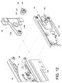
FIG. 12 is an exploded perspective view of the base, the first component, and the housing in the embodiment ofFIG. 1 , showing in particular the first adjusting member and the second adjusting member, which are arranged at the first component and the base respectively; -
FIG. 13 is a schematic drawing in which the panel of the object inFIG. 2 is adjusted to a certain position with respect to the base; -
FIG. 14 is a schematic drawing in which the panel inFIG. 13 is adjusted to another position with respect to the base; -
FIG. 15 is an exploded perspective view of the second component, the base, and the second adjusting member in the embodiment ofFIG. 1 ; -
FIG. 16 shows the second adjusting member inFIG. 15 from a different viewpoint; -
FIG. 17 schematically shows that the base of the mounting mechanism can be adjusted to a first position with respect to the second component by adjusting the second adjusting member; -
FIG. 18 schematically shows that the base of the mounting mechanism can be adjusted to a second position with respect to the second component by adjusting the second adjusting member; -
FIG. 19 schematically shows that the base of the mounting mechanism can be adjusted to a third position with respect to the second component by adjusting the second adjusting member; -
FIG. 20 schematically shows that an external force of a certain direction is applied to the first component inFIG. 2 after the first component is mounted to the second component; -
FIG. 21 schematically shows how the second linking member is driven and consequently pressed against a stop wall by the first component inFIG. 20 due to the external force applied to the first component; -
FIG. 22 is a partial exploded perspective view of the mounting mechanism in the embodiment ofFIG. 1 ; -
FIG. 23 shows the mounting mechanism inFIG. 22 in the assembled state; -
FIG. 23A is a partial enlarged view ofFIG. 23 , showing in particular the manual operation portion corresponding in position to the stopping feature; -
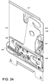
FIG. 24 is an assembled perspective view of the mounting mechanism in another embodiment of the present invention; -
FIG. 25 is an exploded perspective view of the mounting mechanism inFIG. 24 ; -
FIG. 26 is a plan view showing the mounting mechanism inFIG. 24 in a predetermined state; -
FIG. 27 is similar toFIG. 26 , showing the first step of mounting two first components to the mounting mechanism; and -
FIG. 28 is similar toFIG. 27 , showing the second step of mounting two first components to the mounting mechanism. - Referring to
FIG. 1 , thesystem 20 in an embodiment of the present invention includes amain body 22 and at least oneobject 24 to be carried by the main body 22 (hereinafter referred to as the object 24). Thesystem 20 may be a furniture-related system or cabinet-related system. In this embodiment, thesystem 20 includes twoobjects 24, which are implemented as drawers by way of example. For the sake of simplicity, the following description refers to only one of the twoobjects 24. A pair ofslide rail assemblies 26 are mounted between themain body 22 and theobject 24. Theslide rail assemblies 26 in this embodiment are undermount drawer slides, and eachslide rail assembly 26 is mounted adjacent to a lateral bottom portion of theobject 24. This arrangement allows theobject 24 to be pulled out of and pushed back into themain body 22 with ease. - As shown in
FIG. 2 , theslide rail assembly 26 includes afirst rail 28 and asecond rail 30 which can be longitudinally displaced with respect to thefirst rail 28. Preferably, theslide rail assembly 26 further includes athird rail 32 arranged between thefirst rail 28 and thesecond rail 30 to increase the distance by which thesecond rail 30 can be displaced with respect to thefirst rail 28. Theobject 24 at least includes asidewall 34 arranged at thesecond rail 30 and apanel 36 detachably mounted on thesidewall 34. Once mounted on thesidewall 34, thepanel 36 is arranged at afront end portion 38 of thesidewall 34. In addition, afirst component 40 is fixedly arranged at thepanel 36 beforehand and therefore can be viewed as a part of thepanel 36 and as a first furniture component. Thefirst component 40 is configured to mount thepanel 36 to thesidewall 34, as explained in more detail below. - As shown in
FIG. 3 , thesidewall 34 includes a plurality of wall portions assembled together, such as afirst wall portion 42a and asecond wall portion 42b mounted on thefirst wall portion 42a. Also, asecond component 44 is fixedly arranged at thesidewall 34 beforehand and therefore can be viewed as a part of thesidewall 34 and as a second furniture component. In this embodiment, thesecond component 44 is arranged at thefirst wall portion 42a of thesidewall 34 by way of example. - As shown in
FIG. 4 , the mountingmechanism 46 in this embodiment includes abase 48, atransmission device 50, and amovable member 52. Preferably, the mountingmechanism 46 further includes ahousing 54 covering thebase 48. Thehousing 54 may have related operation symbols on its surface in order for an operator to identify the functions provided by the mountingmechanism 46. - As shown in
FIG. 4 andFIG. 5 , thebase 48 is mounted on thesecond component 44. Thebase 48 has anextension wall 58 substantially perpendicularly connected to thebase 48. Theextension wall 58 has a mountingfeature 60, such as a hole. Preferably, the base 48 further includes a first supportingmember 62, a second supportingmember 64, and a protrudingmember 66, all connected to thebase 48. In this embodiment, both the first supportingmember 62 and the second supportingmember 64 are cylindrical. Thetransmission device 50 is arranged at thebaes 48. More specifically, the first supportingmember 62 is inserted into thetransmission device 50 so that thetransmission device 50 can be pivoted with respect to thebase 48. Thetransmission device 50 has apressing section 74. Themovable member 52 is movably connected to thetransmission device 50 and can be displaced with respect to thebase 48. Themovable member 52 includes arack 78, apressing portion 80, a guidingportion 82, and a holdingportion 84. Therack 78 meshes with thetransmission device 50. Thepressing portion 80 is pressed against thepressing section 74 of thetransmission device 50. The guidingportion 82 is inserted by the protrudingmember 66 on thebase 48 and has afirst channel 86 and asecond channel 88. Thesecond channel 88 is in communication with thefirst channel 86 and is tilted by an angle with respect to thefirst channel 86. The holdingportion 84 includes an engagingsection 90 and a guidingsurface 92 adjacent to the engagingsection 90. - The mounting
mechanism 46 further includes anoperation device 94. Theoperation device 94 includes a connectingrod 96 and anelastic member 98. Theelastic member 98 can apply an elastic force to themovable member 52 through the connectingrod 96. More specifically, the connectingrod 96 has ahead 100 and abody 102 connected to thehead 100. A portion of thebody 102 extends out of the mountingfeature 60 of theextension wall 58. Theelastic member 98 is inserted by thebody 102 and is pressed between theextension wall 58 and thehead 100. In addition, afirst linking member 104 and asecond linking member 106 are movably arranged between the connectingrod 96 and thetransmission device 50. More specifically, the second supportingmember 64 is inserted into thefirst linking member 104 so that thefirst linking member 104 can be pivoted with respect to thebase 48. Thefirst linking member 104 includes a plurality ofteeth 108 configured to mesh with thetransmission device 50. Thesecond linking member 106 is movably connected between the connectingrod 96 and thefirst linking member 104. Thesecond linking member 106 can be connected to thefirst linking member 104 by a first connectingmember 110 and to thehead 100 of the connectingrod 96 by a second connectingmember 112. Preferably, thesecond linking member 106 includes amanual operation portion 114 allowing an operator to manually adjust thesecond linking member 106 with a tool. - As shown in
FIG. 6 , thetransmission device 50 is mounted around the first supportingmember 62 on thebase 48. Thetransmission device 50 includes afirst transmission member 68 and asecond transmission member 70. Thefirst transmission member 68 and thesecond transmission member 70 may be integrally formed, or the twotransmission members transmission member first transmission member 68 has a plurality offirst teeth 72, and thesecond transmission member 70 has a plurality ofsecond teeth 76. - As shown in
FIG. 7 , thefirst component 40 includes a firstlongitudinal wall 116a, a secondlongitudinal wall 116b, and atransverse wall 118 connected between the twolongitudinal walls auxiliary portion 120 is also connected between the twolongitudinal walls first adjusting member 122 is arranged at one of the twolongitudinal walls FIG. 7 andFIG. 2 , thetransverse wall 118 can be connected to thepanel 36 of theobject 24. - Referring to
FIG. 8 and FIG. 9 , when the protrudingmember 66 corresponds to thesecond channel 88 of themovable member 52, themovable member 52 is at a first position P1 with respect to thebase 48 for the time being. Themovable member 52 in this state is tilted with respect to thebase 48. On the other hand, thetransmission device 50, thefirst linking member 104, thesecond linking member 106, the connectingrod 96, and theelastic member 98 are each in a predetermined state with respect to themovable member 52. Theelastic member 98 in this predetermined state may store an elastic force if so configured. Referring toFIGS. 8 and 9 in conjunction withFIG. 2 , when it is desired to mount thepanel 36 of theobject 24 to thesidewall 34, an operator moves thefirst component 40 on thepanel 36 in a predetermined direction D. Theauxiliary portion 120 of thefirst component 40 pushes the guidingsurface 92 of themovable member 52 while being moved in the direction D. - Referring to
FIG. 10 and FIG. 11 , as theauxiliary portion 120 of thefirst component 40 continues pushing the guidingsurface 92 of themovable member 52 in the direction D, themovable member 52 is displaced in the same direction from the first position P1 such that the protrudingmember 66 can correspond to thefirst channel 86 of themovable member 52. Themovable member 52 in this state is no longer tilted with respect to thebase 48, and this allows thefirst component 40 to be mounted to themovable member 52. In this embodiment, thefirst component 40 is engageably mounted to the engagingsection 90 of themovable member 52 via theauxiliary portion 120, and during the process, therack 78 of themovable member 52 drives thefirst transmission member 68 of thetransmission device 50. Thesecond transmission member 70, in turn, drives thefirst linking member 104, thesecond linking member 106, and the connectingrod 96 in response to transmission by thefirst transmission member 68. Once the connectingrod 96 is driven from the aforesaid predetermined state to a certain position, themovable member 52 is automatically displaced from the first position P1 to a second position P2 with respect to thebase 48 by the elastic force released by theelastic member 98. More specifically, themovable member 52 is displaced in the direction D toward the second position P2 (seeFIG. 10 ) thanks to therack 78 meshing with thefirst transmission member 68 of thetransmission device 50. When themovable member 52 reaches the second position P2 (seeFIG. 11 ), thefirst component 40 is securely mounted on thesecond component 44. That is to say, thetransmission device 50 can drive themovable member 52 from a first position to a second position in response to thefirst component 40 being mounted to the engagingsection 90 of the holdingportion 84 of themovable member 52. - When it is desired to remove the
first component 40 from thesecond component 44, the operator may insert a tool, such as a screw driver, into themanual operation portion 114 of thesecond linking member 106 and then adjust thesecond linking member 106 manually with the tool, thereby driving the connectingrod 96, thefirst linking member 104, thetransmission device 50, and themovable member 52 sequentially, displacing themovable member 52 from the second position P2 toward the first position P1 with respect to the base 48 in the opposite direction of the direction D. When themovable member 52 is displaced to the first position P1, theauxiliary portion 120 of thefirst component 40 can be disengaged from the engagingsection 90 of the holdingportion 84 of the movable member 52 (the principle of the disengaging operation can be easily understood by referring sequentially toFIG. 11, FIG. 10 ,FIG. 9, and FIG. 8 and is therefore omitted herein for the sake of simplicity). - As shown in
FIG. 12 , thefirst component 40 can be mounted to themovable member 52, and thehousing 54 can be assembled to and thereby cover thebase 48. Moreover, the first adjustingmember 122 arranged at thefirst component 40 includes an adjustingportion 124, a pushingportion 126, and a threadedfeature 128 connected between the adjustingportion 124 and the pushingportion 126. The adjustingportion 124 is designed to correspond to afirst operation hole 130 of thehousing 54. The pushingportion 126 is configured to pass through the twolongitudinal walls base 48. Preferably, the mountingmechanism 46 further includes asecond adjusting member 132 mounted on thebase 48, and an operator can adjust thesecond adjusting member 132 through asecond operation hole 134 of thehousing 54. - As shown in
FIG. 13 and FIG. 14 , the first adjustingmember 122 arranged at thefirst component 40 allows thepanel 36 to be adjusted transversely, or laterally, in position. More specifically, one of the twolongitudinal walls first component 40 has apost 136 with a threaded feature, such as an internal thread (not shown). When an operator adjusts the first adjustingmember 122 through thefirst operation hole 130 of thehousing 54, thefirst component 40 and thepanel 36 are transversely (or laterally) displaced due to threaded engagement between the threadedfeature 128 of the first adjustingmember 122 and the threaded feature of thepost 136. In other words, the transverse (or lateral) position of thepanel 36 can be adjusted in relation to the base 14, thesecond component 44, or thesidewall 34. - Referring to
FIG. 15 , thebase 48 has a plurality offirst holes 138 and asecond hole 140. Thefirst holes 138 and thesecond hole 140 are so shaped that the latter is substantially perpendicular to the former. In this embodiment, thefirst holes 138 extend vertically while thesecond hole 140 extends in the longitudinal direction of thebase 48. The mountingmechanism 46 further includes a plurality of guidingmembers 142. Each guidingmember 142 corresponds to one of thefirst holes 138. More specifically, each guidingmember 142 has a connectingportion 144 and astop 146 connected to the connectingportion 144. The connectingportion 144 of each guidingmember 142 is configured to pass through the correspondingfirst hole 138 of thebase 48 and connect to thesecond component 44, with thestop 146 of the guidingmember 142 stopped on one side of thebase 48. Further, the connectingportion 144 of each guidingmember 142 is smaller than the length of eachfirst hole 138, allowing the base 48 to be movably mounted on thesecond component 44. - As shown in
FIG. 15 and FIG. 16 , thesecond adjusting member 132 includes an adjustingportion 148, apivotal connection portion 150, and aneccentric portion 152 connected between the adjustingportion 148 and thepivotal connection portion 150. The adjustingportion 148 and thepivotal connection portion 150 have a common axis, and theeccentric portion 152 is eccentric with respect to the axis. In other words, the center of theeccentric portion 152 is shifted away from the centers of the adjustingportion 148 and thepivotal connection portion 150. Preferably, thesecond adjusting member 132 further includes astop 154 to be stopped on one side of thebase 48. Thepivotal connection portion 150 is passed through thesecond hole 140 of the base 48 in order to connect pivotally with thesecond component 44. Theeccentric portion 152 is designed to correspond to thesecond hole 140 of thebase 48. - As shown in
FIG. 17, FIG. 18, and FIG. 19 , thebase 48 can be displaced upward and downward by adjusting thesecond adjusting member 132. More specifically, when the adjustingportion 148 is adjusted, theeccentric portion 152 pushes anupper wall 156a or alower wall 156b of thesecond hole 140 of the base 48 such that thebase 48 is displaced upward (seeFIG. 19 ) or downward (seeFIG. 17 ) with respect to thesecond component 44 from the state ofFIG. 18 according to the vertical shape of thefirst holes 138. Thus, referring also toFIG. 20 , when thepanel 36 is mounted to themovable member 52 on the base 48 through thefirst component 40, thepanel 36 can be adjusted upward and downward with respect to thesecond component 44 or thesidewall 34 by adjusting the base 48 upward and downward. - As shown in
FIG. 20 and FIG. 21 , the mountingmechanism 46 in this embodiment may include astop wall 158 connected to thebase 48 and adjacent to thesecond linking member 106. When thefirst component 40 is mounted on thesecond component 44, an external force F applied to thefirst component 40 in the opposite direction of the aforesaid direction D will pull themovable member 52 together with thefirst component 40; as a result, thetransmission device 50, thefirst linking member 104, and thesecond linking member 106 are also driven. In particular, once thesecond linking member 106 is driven, in response to the external force F, to be stopped at thestop wall 158, thefirst component 40 can be prevented from being pulled out with respect to thesecond component 44, and this ensures that thefirst component 40 is mounted on thesecond component 44 in a reliable manner. - As shown in
FIG. 22, FIG. 23, and FIG. 23A , the mountingmechanism 46 further includes a stoppingfeature 160, such as a stop wall arranged at thebase 48. When thesecond linking member 106 is in a predetermined state and at a certain position (referring to the state of thesecond linking member 106 inFIG. 8 and FIG. 9 for the predetermined state), themanual operation portion 114 of thesecond linking member 106 corresponds in position to the stoppingfeature 160 of thebase 48. If, in this state, a tool such as a screw driver (not shown) is inserted into themanual operation portion 114 of thesecond linking member 106 and turned, the front end portion of the screw driver will be stopped by the stoppingfeature 160 of thebase 48, making it impossible for the screw driver to rotate thesecond linking member 106. This ensures that the related components such as thefirst linking member 104 and the connectingrod 96 stay in the predetermined state with respect to thesecond linking member 106. -
FIG. 24 andFIG. 25 show the mountingmechanism 200 in another embodiment of the present invention. The mountingmechanism 200 includes abase 202, atransmission device 204, and amovable member 206. Preferably, ahousing 208 is also included. Thebase 202 is configured in generally the same way as its counterpart in the previous embodiment and is mounted on asecond component 210. A protrudingmember 212 is arranged at thebase 202. Thetransmission device 204 and thehousing 208 are configured in generally the same way as their respective counterparts in the previous embodiment. Themovable member 206 is also configured in generally the same way as its counterpart in the previous embodiment except that themovable member 206 includes two guidingportions portions portions member 212 and arod member 218 respectively, wherein therod member 218 is coupled to thesecond component 210. Each guidingportion first channel second channel second channel first channel movable member 206 is longitudinally extended, and integrally formed, with the two holdingportions portion section surface section second component 210 has astop 227 against which a portion of themovable member 206 can be pressed. - As shown in
FIG. 25 andFIG. 26 , the mountingmechanism 200 preferably further includes adriving device 228 mounted on thesecond component 210. Thedriving device 228 includes a drivingmember 230 and a pushingmember 232. The drivingmember 230 and the pushingmember 232 are pivotally connected to thesecond component 210 bypivotal connection members member 230 has a firstabutting portion 234. The pushingmember 232 has a linkingportion 236 and a secondabutting portion 238. The linkingportion 236 is movably connected to the drivingmember 230. The secondabutting portion 238 corresponds to themovable member 206. More specifically, the pushingmember 232 has aslot 239a and is pivotally connected to the drivingmember 230 by arod element 239b movably passing through theslot 239a. The pushingmember 232 and the drivingmember 230, however, are not necessarily pivotally connected; they may be connected by meshing or by mechanical engagement instead. - Referring to
FIG. 26 , when the protrudingmember 212 and therod member 218 correspond to thesecond channels movable member 206 respectively, themovable member 206 is at a first position P1 with respect to thebase 202 for the time being. In this state, themovable member 206 is tilted with respect to thebase 202, the first abuttingportion 234 of the drivingmember 230 partially extends beyond the front end of thesecond component 210, and the second abuttingportion 238 of the pushingmember 232 is adjacent to themovable member 206. - Referring to
FIG. 27 , this embodiment allows twofirst components 240 to be mounted, wherein eachfirst component 240 is configured in generally the same way as its counterpart in the previous embodiment and has such features as anauxiliary portion 242. In this embodiment, the twofirst components 240 are connected by a connectingmember 244. The operation of mounting the twofirst components 240 begins by moving them in a predetermined direction D. As shown inFIG. 27 , theauxiliary portions 242 of the twofirst components 240 push the guidingsurfaces movable member 206 respectively while being moved in the direction D. On the other hand, the connectingmember 244 between the twofirst components 240 pushes the first abuttingportion 234 of the drivingmember 230, and the pushingmember 232 is pivoted in response to the drivingmember 230. Themovable member 206, therefore, is pushed by the second abuttingportion 238 of the pushingmember 232. With a portion of themovable member 206 pressed against thestop 227 of thesecond component 210, a better supporting effect is achieved during the mounting operation. - Referring to
FIG. 28 , as theauxiliary portions 242 of thefirst components 240 continue pushing the guidingsurfaces movable member 206 in the direction D respectively, themovable member 206 is displaced in the same direction from the first position P1 to a second position P2 such that the protrudingmember 212 and therod member 218 correspond to thefirst channels movable member 206 respectively. Themovable member 206 in this state is no longer tilted with respect to thebase 202, and this allows the twofirst components 240 to be mounted to themovable member 206. In this embodiment, the twofirst components 240 are respectively and engageably mounted to the engagingsections movable member 206 via the auxiliary portions 242 (the principle of interaction between the movable member and the transmission device can be easily understood by referring sequentially toFIG. 8, FIG. 9 ,FIG. 10, and FIG. 11 and is therefore omitted herein for the sake of simplicity). - While the present invention has been disclosed by way of the foregoing preferred embodiments, the embodiments are not intended to be restrictive of the scope of the invention. The scope of patent protection sought by the applicant is defined by the appended claims.
Claims (23)
- A mounting mechanism (46, 200) adapted for mounting at least one first component (40, 240) to a second component (44, 210), the mounting mechanism (46, 200) comprising:a base (48, 202) mountable on the second component (44, 210);characterized in thatthe mounting mechanism (46, 200) further comprises a transmission device (50, 204) and a movable member (52, 206) movably connected to the transmission device (50, 204);wherein the transmission device (50, 204) is arranged at the base (48, 202), and the movable member (52, 206) is configured to be displaced with respect to the base (48, 202) from a first position (P1) to a second position (P2) in response to displacement between the at least one first component (40, 240) and the second component (44, 210) in a predetermined direction (D), thereby mounting the at least one first component (40, 240) to the second component (44, 210).
- The mounting mechanism (46) as claimed in claim 1, wherein the movable member (52) includes a guiding portion (82), the guiding portion (82) has a first channel (86) and a second channel (88) in communication with and tilted by an angle with respect to the first channel (86), the mounting mechanism (46) further comprises a protruding member (66) selectively extending through a corresponding one of the first channel (86) and the second channel (88), and the movable member (52) is at the first position (P1) with respect to the base (48) when the protruding member (66) corresponds to the second channel (88).
- The mounting mechanism (46) as claimed in claim 1, wherein the movable member (52) includes a holding portion (84), the holding portion (84) includes an engaging section (90) and a guiding surface (92) adjacent to the engaging section (90), and an auxiliary portion (120) of the at least one first component (40) is allowed to push the guiding surface (92) of the movable member (52) and to be engageably mounted to the engaging section (90).
- The mounting mechanism (46, 200) as claimed in claim 1, wherein the at least one first component (40, 240) includes two corresponding longitudinal walls (116a, 116b) and an auxiliary portion (120, 242) connected between the two longitudinal walls (116a, 116b); one of the two longitudinal walls (116a, 116b) of the at least one first component (40, 240) has a post (136); the auxiliary portion (120, 242) is mountable to the movable member (52, 206); a first adjusting member (122) is arranged at the at least one first component (40, 240) and includes an adjusting portion (124), a pushing portion (126), and a threaded feature (128) connected between the adjusting portion (124) and the pushing portion (126); the threaded feature (128) is threadedly connectable to the post (136); the pushing portion (126) corresponds to the base (48, 202); and the at least one first component (40, 240) is displaceable in a transverse direction according to adjustment of the first adjusting member (122).
- The mounting mechanism (46, 200) as claimed in claim 1, wherein the base (48, 202) includes a first hole (138) and a second hole (140); the second hole (140) has a shape substantially perpendicular to a shape of the first hole (138); the mounting mechanism (46, 200) further comprises a guiding member (142) and a second adjusting member (132); the guiding member (142) has a connecting portion (144) and a stop (146) connected to the connecting portion (144); the connecting portion (144) extends through the first hole (138) and is connectable to the second component (44, 210) such that the stop (146) is stopped on a side of the base (48, 202); the second adjusting member (132) corresponds to the second hole (140) of the base (48, 202) and includes an adjusting portion (148), a pivotal connection portion (150), and an eccentric portion (152) connected between the adjusting portion (148) and the pivotal connection portion (150) of the second adjusting member (132); the adjusting portion (148) and the pivotal connection portion (150) have a common axis; the pivotal connection portion (150) is pivotally connectable to the second component (44, 210); and the eccentric portion (152) is eccentric with respect to the axis and is configured to push the base (48, 202) in order to displace the base (48, 202) according to the shape of the first hole (138).
- The mounting mechanism (46, 200) as claimed in claim 1, wherein the first component (40, 240) is a first furniture component, and the second component (44, 210) is a second furniture component.
- The mounting mechanism (46, 200) as claimed in claim 1, wherein the movable member (52, 206) is movably mounted on the base (48, 202), the movable member (52, 206) includes at least one holding portion (84, 216a, 216b) to which the at least one first component (40, 240) is mountable, the transmission device (50, 204) is configured to displace the movable member (52, 206) from the first position (P1) to the second position (P2) in response to the at least one first component (40, 240) being mounted to the holding portion (84, 216a, 216b) of the movable member (52, 206).
- The mounting mechanism (46, 200) as claimed in any one of claims 1-7, wherein the movable member (52, 206) is connected to the transmission device (50, 204) in a meshing manner.
- The mounting mechanism (46, 200) as claimed in any one of claims 1-8, wherein the transmission device (50, 204) includes a first transmission member (68) with a plurality of first teeth (72), and the movable member (52, 206) includes a rack (78) meshing with the first teeth (72) of the first transmission member (68).
- The mounting mechanism (46, 200) as claimed in claim 9, wherein the transmission device (50, 204) includes a second transmission member (70) with a plurality of second teeth (76), and the mounting mechanism (46, 200) further comprises a first linking member (104) with a plurality of teeth (108) meshing with the second teeth (76) of the second transmission member (70).
- The mounting mechanism (46, 200) as claimed in claim 10, further comprising a second linking member (106) and a connecting rod (96), wherein the first linking member (104) is pivotally connected to the base (48, 202), and the second linking member (106) is movably connected between the first linking member (104) and the connecting rod (96).
- The mounting mechanism (46, 200) as claimed in claim 11, further comprising an elastic member (98), wherein the elastic member (98) is mounted on the connecting rod (96) and is configured to apply an elastic force to the movable member (52, 206).
- The mounting mechanism (46, 200) as claimed in claim 12, further comprising an extension wall (58) connected to the base (48, 202), the extension wall (58) having a mounting feature (60), the connecting rod (96) having a head (100) and a body (102) connected to the head (100), the body (102) partially extending out of the mounting feature (60), the elastic member (98) being pressed between the extension wall (58) and the head (100).
- The mounting mechanism (46, 200) as claimed in claim 13, wherein the second linking member (106) is movably connected between the first linking member (104) and the head (100) of the connecting rod (96).
- The mounting mechanism (46, 200) as claimed in any one of claims 11-14, wherein the second linking member (106) includes a manual operation portion (114) with which the second linking member (106) is manually adjustable in order to bring the movable member (52, 206) from the second position (P2) to the first position (P1) with respect to the base (48, 202).
- The mounting mechanism (46, 200) as claimed in claim 15, further comprising a stopping feature (160) arranged at the base (48, 202), wherein the manual operation portion (114) of the second linking member (106) corresponds in position to the stopping feature (160) when the second linking member (106) is at a predetermined position.
- The mounting mechanism (46, 200) as claimed in any one of claims 11-16, further comprising a stop wall (158) adjacent to the second linking member (106), wherein the stop wall (158) stops the second linking member (106) in response to an external force (F) applied in an opposite direction of the predetermined direction (D) to the at least one first component (40, 240).
- The mounting mechanism (200) as claimed in claim 1 or 7, wherein the movable member (206) includes two holding portions (216a, 216b) to which two first components (240) are respectively and engageably mountable.
- The mounting mechanism (200) as claimed in claim 18, wherein each of the holding portions (216a, 216b) includes an engaging section (224a, 224b) and a guiding surface (226a, 226b) adjacent to the engaging section (224a, 224b), and each of the two first components (240) has an auxiliary portion (242) for pushing a corresponding one of the guiding surfaces (226a, 226b) of the movable member (206) and to be engageably mounted to a corresponding one of the engaging sections (224a, 224b).
- The mounting mechanism (200) as claimed in claim 18, wherein the movable member (206) includes two guiding portions (214a, 214b), each of the guiding portions (214a, 214b) has a first channel (220a, 220b) and a second channel (222a, 222b) in communication with and tilted by an angle with respect to the first channel (220a, 220b), the mounting mechanism (200) further comprises a protruding member (212) and a rod member (218), the protruding member (212) and the rod member (218) extend through the two guiding portions (214a, 214b) respectively, and the movable member (206) is at the first position (P1) with respect to the base (202) when the protruding member (212) and the rod member (218) each correspond to a corresponding one of the second channels (222a, 222b).
- The mounting mechanism (200) as claimed in claim 18, further comprising a driving device (228) mountable on the second component (210), wherein the driving device (228) has a pushing member (232), and when displaced in the predetermined direction (D) the two first components (240) drive the driving device (228) such that the movable member (206) is displaced from the first position (P1) toward the second position (P2) in response to pushing of the pushing member (232) of the driving device (228).
- The mounting mechanism (200) as claimed in claim 21, wherein the driving device (228) includes a driving member (230), both the driving member (230) and the pushing member (232) are pivotally connectable to the second component (210), the pushing member (232) is movably connected to the driving member (230), and the driving member (230) is configured to be driven by the two first components (240) in order to drive the pushing member (232).
- The mounting mechanism (46, 200) as claimed in claim 1, wherein the mounting mechanism (46, 200) is adapted for use in a system (20) including a main body (22) and an object (24) mounted to the main body (22) via a slide rail assembly (26), the slide rail assembly (26) including a first rail (28) and a second rail (30) displaceable with respect to the first rail (28), the object (24) including a sidewall (34) and a panel (36), in which the sidewall (34) is arranged at the second rail (30), and the panel (36) is mounted to the second component (44, 210) of the sidewall (34) via the first component (40, 240);
wherein the movable member (52, 206) includes a rack (78);
wherein the transmission device (50, 204) is configured to displace the movable member (52, 206) from the first position (P1) to the second position (P2) in response to the first component (40, 240) being mounted to the movable member (52, 206), wherein the transmission device (50, 204) includes a first transmission member (68) with a plurality of first teeth (72) and a second transmission member (70) with a plurality of second teeth (76), and the first teeth (72) of the first transmission member (68) mesh with the rack (78) of the movable member (52, 206);
wherein the mounting mechanism (46, 200) further comprises a first linking member (104) and a second linking member (106) connected to the first linking member (104);
wherein the first linking member (104) is pivotally connected to the base (48, 202) and includes a plurality of teeth (108) meshing with the second teeth (76) of the second transmission member (70), and the second linking member (106) is connected to a connecting rod (96); and
wherein an elastic member (98) is mounted on the connecting rod (96) and is configured to apply an elastic force to the movable member (52, 206).
Applications Claiming Priority (2)
| Application Number | Priority Date | Filing Date | Title |
|---|---|---|---|
| TW104137456A TWI548368B (en) | 2015-11-12 | 2015-11-12 | Mounting mechanism |
| TW105121079A TWI603694B (en) | 2016-07-01 | 2016-07-01 | Mounting mechanism |
Publications (2)
| Publication Number | Publication Date |
|---|---|
| EP3167760A1 true EP3167760A1 (en) | 2017-05-17 |
| EP3167760B1 EP3167760B1 (en) | 2018-06-13 |
Family
ID=57189797
Family Applications (1)
| Application Number | Title | Priority Date | Filing Date |
|---|---|---|---|
| EP16194105.9A Active EP3167760B1 (en) | 2015-11-12 | 2016-10-17 | Mounting mechanism |
Country Status (3)
| Country | Link |
|---|---|
| US (1) | US10010174B2 (en) |
| EP (1) | EP3167760B1 (en) |
| JP (1) | JP6393723B2 (en) |
Cited By (5)
| Publication number | Priority date | Publication date | Assignee | Title |
|---|---|---|---|---|
| CN109602191A (en) * | 2018-12-26 | 2019-04-12 | 海宁亿诚五金有限公司 | A kind of connector of side plate of the drawer and panel |
| CN111465334A (en) * | 2017-11-07 | 2020-07-28 | 优利思百隆有限公司 | Fastening device for detachably fastening a front panel to a drawer |
| CN111712159A (en) * | 2017-12-21 | 2020-09-25 | 优利思百隆有限公司 | Drawer side wall with covering section bar |
| US11576487B2 (en) * | 2018-10-05 | 2023-02-14 | Julius Blum Gmbh | Securing device for detachably securing a front panel to a drawer |
| WO2024028761A1 (en) * | 2022-08-02 | 2024-02-08 | Formenti & Giovenzana S.P.A. | Attachment device for attaching a panel to a furnishing element |
Families Citing this family (4)
| Publication number | Priority date | Publication date | Assignee | Title |
|---|---|---|---|---|
| PL3621483T3 (en) * | 2017-05-09 | 2021-12-13 | Samet Kalip Ve Madeni Esya San. Ve Tic. A.S. | Retaining device for a front panel of a drawer |
| ES2940615T3 (en) * | 2017-05-09 | 2023-05-09 | Samet Kalip Ve Madeni Esya San Ve Tic A S | Clamping device for a front panel of a drawer |
| EP3621485B1 (en) * | 2017-05-10 | 2023-02-08 | Wolfgang Held | Anchorage fitting for a front panel |
| DE102017127022A1 (en) * | 2017-11-16 | 2019-05-16 | Paul Hettich Gmbh & Co. Kg | Fastening device for a panel of a drawer |
Citations (10)
| Publication number | Priority date | Publication date | Assignee | Title |
|---|---|---|---|---|
| CN102058253A (en) * | 2010-10-27 | 2011-05-18 | 世塑有限公司 | Angle adjusting structure of drawer panel |
| WO2012068599A1 (en) * | 2010-11-23 | 2012-05-31 | Julius Blum Gmbh | Furniture fitting for fastening a front panel |
| US8297724B2 (en) | 2007-07-11 | 2012-10-30 | Julius Blum Gmbh | Drawer frame with a fastening device for a front panel |
| WO2013025181A2 (en) * | 2011-08-16 | 2013-02-21 | SAMET KALIP VE MADENI ESYA SANAYI VE TICARET ΑΝΟΝΪΜ SJRKETi | Door locking mechanism for drawers |
| US20140070687A1 (en) | 2011-05-24 | 2014-03-13 | Julius Blum Gmbh | Fastening device for mounting a front cover on a drawer |
| US20140072366A1 (en) | 2011-05-24 | 2014-03-13 | Julius Blum Gmbh | Fastening device for fastening a front panel on a drawer |
| US20140077677A1 (en) | 2011-05-24 | 2014-03-20 | Julius Blum Gmbh | Fastening device for mounting a front cover on a drawer |
| US20140252936A1 (en) | 2011-11-22 | 2014-09-11 | Julius Blum Gmbh | Fixing device with spacer |
| EP2868229A1 (en) * | 2013-10-31 | 2015-05-06 | Guangdong Taiming Metal Products Co., Ltd. | Panel dismounting and locking mechanism of drawer |
| DE202015102087U1 (en) * | 2014-11-10 | 2015-07-27 | Guangdong Taiming Metal Products Co. Ltd. (China Limited Company) | Dismantling and assembly adjustment device for drawer panel |
Family Cites Families (16)
| Publication number | Priority date | Publication date | Assignee | Title |
|---|---|---|---|---|
| IT219343Z2 (en) * | 1990-03-26 | 1993-02-22 | DEVICE FOR FIXING AND POSITIONING THE FRONT PANEL, COMPARED TO THE SIDES OF KITCHEN DRAWERS AND FURNITURE IN GENERAL | |
| DE4305074A1 (en) * | 1993-02-19 | 1994-08-25 | Lautenschlaeger Mepla Werke | Fastening fitting for drawer front panels |
| AT402778B (en) * | 1993-09-21 | 1997-08-25 | Blum Gmbh Julius | Device for fixing the front panel of a drawer to drawer sides |
| DE9421872U1 (en) * | 1993-07-28 | 1996-12-19 | Blum Gmbh Julius | Device for fastening the front panel of a drawer to drawer frames |
| AT404664B (en) * | 1995-03-20 | 1999-01-25 | Blum Gmbh Julius | DEVICE FOR FASTENING THE FRONT PANEL OF A DRAWER ON DRAWER FRAMES |
| DE29914388U1 (en) * | 1998-09-16 | 1999-12-09 | Blum Gmbh Julius | Device for fastening the front panel of a drawer |
| ES2267317B1 (en) * | 2001-09-27 | 2007-08-01 | Miguel Angel Rioja Calvo | DEVICE FOR ASSEMBLY AND DISASSEMBLY WITHOUT TOOLS FROM THE FURNITURE DRAWER FRONT. |
| AT503418B1 (en) * | 2006-03-28 | 2007-10-15 | Blum Gmbh Julius | DRAWER WITH AT LEAST ONE WOODEN DRAWER WALL |
| DE202007001780U1 (en) * | 2006-09-08 | 2008-01-10 | Paul Hettich Gmbh & Co. Kg | drawer |
| CN201403824Y (en) * | 2009-04-08 | 2010-02-17 | 世塑有限公司 | Drawer panel combining element |
| IT1399617B1 (en) * | 2010-04-10 | 2013-04-26 | Formenti & Giovenzana | FIXING DEVICE FOR FIXING A PANEL TO A FURNISHING ELEMENT |
| CN203302661U (en) * | 2013-04-23 | 2013-11-27 | 广东泰明金属制品有限公司 | Regulating device for drawer panel |
| CN203609054U (en) * | 2013-10-31 | 2014-05-28 | 广东泰明金属制品有限公司 | Dismounting, mounting and locking mechanism for drawer panel |
| DE102014011090A1 (en) * | 2014-07-30 | 2016-02-04 | Erwin Krüger | Mounting fitting for a panel on an open end of a drawer |
| DE102015102771A1 (en) * | 2015-02-26 | 2016-09-01 | Paul Hettich Gmbh & Co. Kg | Drawer and cover carrier for a front panel of a drawer |
| AT516933B1 (en) * | 2015-03-13 | 2019-11-15 | Blum Gmbh Julius | Fastening device for releasably securing a front panel to a drawer |
-
2016
- 2016-10-07 US US15/288,134 patent/US10010174B2/en active Active
- 2016-10-17 EP EP16194105.9A patent/EP3167760B1/en active Active
- 2016-10-20 JP JP2016205881A patent/JP6393723B2/en active Active
Patent Citations (11)
| Publication number | Priority date | Publication date | Assignee | Title |
|---|---|---|---|---|
| US8297724B2 (en) | 2007-07-11 | 2012-10-30 | Julius Blum Gmbh | Drawer frame with a fastening device for a front panel |
| CN102058253A (en) * | 2010-10-27 | 2011-05-18 | 世塑有限公司 | Angle adjusting structure of drawer panel |
| WO2012068599A1 (en) * | 2010-11-23 | 2012-05-31 | Julius Blum Gmbh | Furniture fitting for fastening a front panel |
| US8727461B2 (en) | 2010-11-23 | 2014-05-20 | Julius Blum Gmbh | Furniture fitting for fastening a front panel |
| US20140070687A1 (en) | 2011-05-24 | 2014-03-13 | Julius Blum Gmbh | Fastening device for mounting a front cover on a drawer |
| US20140072366A1 (en) | 2011-05-24 | 2014-03-13 | Julius Blum Gmbh | Fastening device for fastening a front panel on a drawer |
| US20140077677A1 (en) | 2011-05-24 | 2014-03-20 | Julius Blum Gmbh | Fastening device for mounting a front cover on a drawer |
| WO2013025181A2 (en) * | 2011-08-16 | 2013-02-21 | SAMET KALIP VE MADENI ESYA SANAYI VE TICARET ΑΝΟΝΪΜ SJRKETi | Door locking mechanism for drawers |
| US20140252936A1 (en) | 2011-11-22 | 2014-09-11 | Julius Blum Gmbh | Fixing device with spacer |
| EP2868229A1 (en) * | 2013-10-31 | 2015-05-06 | Guangdong Taiming Metal Products Co., Ltd. | Panel dismounting and locking mechanism of drawer |
| DE202015102087U1 (en) * | 2014-11-10 | 2015-07-27 | Guangdong Taiming Metal Products Co. Ltd. (China Limited Company) | Dismantling and assembly adjustment device for drawer panel |
Cited By (9)
| Publication number | Priority date | Publication date | Assignee | Title |
|---|---|---|---|---|
| CN111465334A (en) * | 2017-11-07 | 2020-07-28 | 优利思百隆有限公司 | Fastening device for detachably fastening a front panel to a drawer |
| CN111465334B (en) * | 2017-11-07 | 2021-09-28 | 优利思百隆有限公司 | Fastening device for detachably fastening a front panel to a drawer |
| US11197546B2 (en) | 2017-11-07 | 2021-12-14 | Julius Blum Gmbh | Securing device for detachably securing a front panel on a drawer |
| CN111712159A (en) * | 2017-12-21 | 2020-09-25 | 优利思百隆有限公司 | Drawer side wall with covering section bar |
| JP2021506489A (en) * | 2017-12-21 | 2021-02-22 | ユリウス ブルーム ゲー・エム・ベー・ハーJulius Blum GmbH | Drawer side wall with cover profile |
| US11213125B2 (en) | 2017-12-21 | 2022-01-04 | Julius Blum Gmbh | Drawer side wall having a cover profile |
| US11576487B2 (en) * | 2018-10-05 | 2023-02-14 | Julius Blum Gmbh | Securing device for detachably securing a front panel to a drawer |
| CN109602191A (en) * | 2018-12-26 | 2019-04-12 | 海宁亿诚五金有限公司 | A kind of connector of side plate of the drawer and panel |
| WO2024028761A1 (en) * | 2022-08-02 | 2024-02-08 | Formenti & Giovenzana S.P.A. | Attachment device for attaching a panel to a furnishing element |
Also Published As
| Publication number | Publication date |
|---|---|
| JP2017086895A (en) | 2017-05-25 |
| EP3167760B1 (en) | 2018-06-13 |
| JP6393723B2 (en) | 2018-09-19 |
| US10010174B2 (en) | 2018-07-03 |
| US20170135473A1 (en) | 2017-05-18 |
Similar Documents
| Publication | Publication Date | Title |
|---|---|---|
| EP3167760B1 (en) | Mounting mechanism | |
| JP6647219B2 (en) | Furniture support frame | |
| EP3082387B1 (en) | Slide rail assembly | |
| US9723746B2 (en) | Slide rail assembly | |
| EP3153065A1 (en) | Mounting part for slide rail assembly | |
| EP3068199A2 (en) | Slide rail assembly | |
| US20160278234A1 (en) | Slide rail assembly | |
| EP3199061B1 (en) | Slide rail assembly | |
| EP3167756A1 (en) | Quick-release mechanism for drawer slide parts | |
| EP3094166B1 (en) | Slide rail assembly | |
| TWI593339B (en) | Slide rail assembly and bracket device thereof | |
| US9642460B2 (en) | Self-closing slide rail assembly and self-closing mechanism thereof | |
| US10470569B2 (en) | Coupling mechanism and slide rail assembly for furniture part | |
| EP3144457A1 (en) | Slide rail assembly with interlock device | |
| US9750346B2 (en) | Drawer slide assembly | |
| CN107019356B (en) | Sliding rail assembly | |
| CN104939546B (en) | Pull-out guide portion for drawer | |
| EP2929804A1 (en) | Slide rail system and connecting device used for slide rail assembly | |
| CN107581807B (en) | Mounting mechanism | |
| EP3251555A1 (en) | Drawer slide rail | |
| EP3045074A1 (en) | Slide rail assembly and mounting device thereof | |
| EP3804565A1 (en) | Cabinet and slide rail kit thereof | |
| CN106820676A (en) | Installing mechanism | |
| TWI603694B (en) | Mounting mechanism | |
| EP2965658B1 (en) | Drawer slide rail assembly |
Legal Events
| Date | Code | Title | Description |
|---|---|---|---|
| PUAI | Public reference made under article 153(3) epc to a published international application that has entered the european phase |
Free format text: ORIGINAL CODE: 0009012 |
|
| AK | Designated contracting states |
Kind code of ref document: A1 Designated state(s): AL AT BE BG CH CY CZ DE DK EE ES FI FR GB GR HR HU IE IS IT LI LT LU LV MC MK MT NL NO PL PT RO RS SE SI SK SM TR |
|
| AX | Request for extension of the european patent |
Extension state: BA ME |
|
| 17P | Request for examination filed |
Effective date: 20170704 |
|
| RBV | Designated contracting states (corrected) |
Designated state(s): AL AT BE BG CH CY CZ DE DK EE ES FI FR GB GR HR HU IE IS IT LI LT LU LV MC MK MT NL NO PL PT RO RS SE SI SK SM TR |
|
| GRAP | Despatch of communication of intention to grant a patent |
Free format text: ORIGINAL CODE: EPIDOSNIGR1 |
|
| INTG | Intention to grant announced |
Effective date: 20180108 |
|
| GRAS | Grant fee paid |
Free format text: ORIGINAL CODE: EPIDOSNIGR3 |
|
| GRAA | (expected) grant |
Free format text: ORIGINAL CODE: 0009210 |
|
| AK | Designated contracting states |
Kind code of ref document: B1 Designated state(s): AL AT BE BG CH CY CZ DE DK EE ES FI FR GB GR HR HU IE IS IT LI LT LU LV MC MK MT NL NO PL PT RO RS SE SI SK SM TR |
|
| REG | Reference to a national code |
Ref country code: GB Ref legal event code: FG4D |
|
| REG | Reference to a national code |
Ref country code: CH Ref legal event code: EP Ref country code: AT Ref legal event code: REF Ref document number: 1007575 Country of ref document: AT Kind code of ref document: T Effective date: 20180615 |
|
| REG | Reference to a national code |
Ref country code: DE Ref legal event code: R096 Ref document number: 602016003566 Country of ref document: DE |
|
| REG | Reference to a national code |
Ref country code: IE Ref legal event code: FG4D |
|
| REG | Reference to a national code |
Ref country code: NL Ref legal event code: MP Effective date: 20180613 |
|
| REG | Reference to a national code |
Ref country code: LT Ref legal event code: MG4D |
|
| PG25 | Lapsed in a contracting state [announced via postgrant information from national office to epo] |
Ref country code: CY Free format text: LAPSE BECAUSE OF FAILURE TO SUBMIT A TRANSLATION OF THE DESCRIPTION OR TO PAY THE FEE WITHIN THE PRESCRIBED TIME-LIMIT Effective date: 20180613 Ref country code: SE Free format text: LAPSE BECAUSE OF FAILURE TO SUBMIT A TRANSLATION OF THE DESCRIPTION OR TO PAY THE FEE WITHIN THE PRESCRIBED TIME-LIMIT Effective date: 20180613 Ref country code: NO Free format text: LAPSE BECAUSE OF FAILURE TO SUBMIT A TRANSLATION OF THE DESCRIPTION OR TO PAY THE FEE WITHIN THE PRESCRIBED TIME-LIMIT Effective date: 20180913 Ref country code: LT Free format text: LAPSE BECAUSE OF FAILURE TO SUBMIT A TRANSLATION OF THE DESCRIPTION OR TO PAY THE FEE WITHIN THE PRESCRIBED TIME-LIMIT Effective date: 20180613 Ref country code: FI Free format text: LAPSE BECAUSE OF FAILURE TO SUBMIT A TRANSLATION OF THE DESCRIPTION OR TO PAY THE FEE WITHIN THE PRESCRIBED TIME-LIMIT Effective date: 20180613 Ref country code: BG Free format text: LAPSE BECAUSE OF FAILURE TO SUBMIT A TRANSLATION OF THE DESCRIPTION OR TO PAY THE FEE WITHIN THE PRESCRIBED TIME-LIMIT Effective date: 20180913 |
|
| PG25 | Lapsed in a contracting state [announced via postgrant information from national office to epo] |
Ref country code: HR Free format text: LAPSE BECAUSE OF FAILURE TO SUBMIT A TRANSLATION OF THE DESCRIPTION OR TO PAY THE FEE WITHIN THE PRESCRIBED TIME-LIMIT Effective date: 20180613 Ref country code: RS Free format text: LAPSE BECAUSE OF FAILURE TO SUBMIT A TRANSLATION OF THE DESCRIPTION OR TO PAY THE FEE WITHIN THE PRESCRIBED TIME-LIMIT Effective date: 20180613 Ref country code: LV Free format text: LAPSE BECAUSE OF FAILURE TO SUBMIT A TRANSLATION OF THE DESCRIPTION OR TO PAY THE FEE WITHIN THE PRESCRIBED TIME-LIMIT Effective date: 20180613 Ref country code: GR Free format text: LAPSE BECAUSE OF FAILURE TO SUBMIT A TRANSLATION OF THE DESCRIPTION OR TO PAY THE FEE WITHIN THE PRESCRIBED TIME-LIMIT Effective date: 20180914 |
|
| REG | Reference to a national code |
Ref country code: AT Ref legal event code: MK05 Ref document number: 1007575 Country of ref document: AT Kind code of ref document: T Effective date: 20180613 |
|
| PG25 | Lapsed in a contracting state [announced via postgrant information from national office to epo] |
Ref country code: NL Free format text: LAPSE BECAUSE OF FAILURE TO SUBMIT A TRANSLATION OF THE DESCRIPTION OR TO PAY THE FEE WITHIN THE PRESCRIBED TIME-LIMIT Effective date: 20180613 |
|
| PG25 | Lapsed in a contracting state [announced via postgrant information from national office to epo] |
Ref country code: AT Free format text: LAPSE BECAUSE OF FAILURE TO SUBMIT A TRANSLATION OF THE DESCRIPTION OR TO PAY THE FEE WITHIN THE PRESCRIBED TIME-LIMIT Effective date: 20180613 Ref country code: SK Free format text: LAPSE BECAUSE OF FAILURE TO SUBMIT A TRANSLATION OF THE DESCRIPTION OR TO PAY THE FEE WITHIN THE PRESCRIBED TIME-LIMIT Effective date: 20180613 Ref country code: PL Free format text: LAPSE BECAUSE OF FAILURE TO SUBMIT A TRANSLATION OF THE DESCRIPTION OR TO PAY THE FEE WITHIN THE PRESCRIBED TIME-LIMIT Effective date: 20180613 Ref country code: EE Free format text: LAPSE BECAUSE OF FAILURE TO SUBMIT A TRANSLATION OF THE DESCRIPTION OR TO PAY THE FEE WITHIN THE PRESCRIBED TIME-LIMIT Effective date: 20180613 Ref country code: IS Free format text: LAPSE BECAUSE OF FAILURE TO SUBMIT A TRANSLATION OF THE DESCRIPTION OR TO PAY THE FEE WITHIN THE PRESCRIBED TIME-LIMIT Effective date: 20181013 Ref country code: RO Free format text: LAPSE BECAUSE OF FAILURE TO SUBMIT A TRANSLATION OF THE DESCRIPTION OR TO PAY THE FEE WITHIN THE PRESCRIBED TIME-LIMIT Effective date: 20180613 Ref country code: CZ Free format text: LAPSE BECAUSE OF FAILURE TO SUBMIT A TRANSLATION OF THE DESCRIPTION OR TO PAY THE FEE WITHIN THE PRESCRIBED TIME-LIMIT Effective date: 20180613 |
|
| PG25 | Lapsed in a contracting state [announced via postgrant information from national office to epo] |
Ref country code: ES Free format text: LAPSE BECAUSE OF FAILURE TO SUBMIT A TRANSLATION OF THE DESCRIPTION OR TO PAY THE FEE WITHIN THE PRESCRIBED TIME-LIMIT Effective date: 20180613 Ref country code: IT Free format text: LAPSE BECAUSE OF FAILURE TO SUBMIT A TRANSLATION OF THE DESCRIPTION OR TO PAY THE FEE WITHIN THE PRESCRIBED TIME-LIMIT Effective date: 20180613 Ref country code: SM Free format text: LAPSE BECAUSE OF FAILURE TO SUBMIT A TRANSLATION OF THE DESCRIPTION OR TO PAY THE FEE WITHIN THE PRESCRIBED TIME-LIMIT Effective date: 20180613 |
|
| REG | Reference to a national code |
Ref country code: DE Ref legal event code: R097 Ref document number: 602016003566 Country of ref document: DE |
|
| PLBE | No opposition filed within time limit |
Free format text: ORIGINAL CODE: 0009261 |
|
| STAA | Information on the status of an ep patent application or granted ep patent |
Free format text: STATUS: NO OPPOSITION FILED WITHIN TIME LIMIT |
|
| 26N | No opposition filed |
Effective date: 20190314 |
|
| PG25 | Lapsed in a contracting state [announced via postgrant information from national office to epo] |
Ref country code: DK Free format text: LAPSE BECAUSE OF FAILURE TO SUBMIT A TRANSLATION OF THE DESCRIPTION OR TO PAY THE FEE WITHIN THE PRESCRIBED TIME-LIMIT Effective date: 20180613 Ref country code: SI Free format text: LAPSE BECAUSE OF FAILURE TO SUBMIT A TRANSLATION OF THE DESCRIPTION OR TO PAY THE FEE WITHIN THE PRESCRIBED TIME-LIMIT Effective date: 20180613 |
|
| REG | Reference to a national code |
Ref country code: BE Ref legal event code: MM Effective date: 20181031 |
|
| PG25 | Lapsed in a contracting state [announced via postgrant information from national office to epo] |
Ref country code: LU Free format text: LAPSE BECAUSE OF NON-PAYMENT OF DUE FEES Effective date: 20181017 Ref country code: MC Free format text: LAPSE BECAUSE OF FAILURE TO SUBMIT A TRANSLATION OF THE DESCRIPTION OR TO PAY THE FEE WITHIN THE PRESCRIBED TIME-LIMIT Effective date: 20180613 |
|
| PG25 | Lapsed in a contracting state [announced via postgrant information from national office to epo] |
Ref country code: BE Free format text: LAPSE BECAUSE OF NON-PAYMENT OF DUE FEES Effective date: 20181031 Ref country code: FR Free format text: LAPSE BECAUSE OF NON-PAYMENT OF DUE FEES Effective date: 20181031 |
|
| PG25 | Lapsed in a contracting state [announced via postgrant information from national office to epo] |
Ref country code: AL Free format text: LAPSE BECAUSE OF FAILURE TO SUBMIT A TRANSLATION OF THE DESCRIPTION OR TO PAY THE FEE WITHIN THE PRESCRIBED TIME-LIMIT Effective date: 20180613 |
|
| PG25 | Lapsed in a contracting state [announced via postgrant information from national office to epo] |
Ref country code: MT Free format text: LAPSE BECAUSE OF NON-PAYMENT OF DUE FEES Effective date: 20181017 |
|
| PG25 | Lapsed in a contracting state [announced via postgrant information from national office to epo] |
Ref country code: TR Free format text: LAPSE BECAUSE OF FAILURE TO SUBMIT A TRANSLATION OF THE DESCRIPTION OR TO PAY THE FEE WITHIN THE PRESCRIBED TIME-LIMIT Effective date: 20180613 |
|
| PG25 | Lapsed in a contracting state [announced via postgrant information from national office to epo] |
Ref country code: PT Free format text: LAPSE BECAUSE OF FAILURE TO SUBMIT A TRANSLATION OF THE DESCRIPTION OR TO PAY THE FEE WITHIN THE PRESCRIBED TIME-LIMIT Effective date: 20180613 |
|
| REG | Reference to a national code |
Ref country code: CH Ref legal event code: PL |
|
| PG25 | Lapsed in a contracting state [announced via postgrant information from national office to epo] |
Ref country code: MK Free format text: LAPSE BECAUSE OF NON-PAYMENT OF DUE FEES Effective date: 20180613 Ref country code: HU Free format text: LAPSE BECAUSE OF FAILURE TO SUBMIT A TRANSLATION OF THE DESCRIPTION OR TO PAY THE FEE WITHIN THE PRESCRIBED TIME-LIMIT; INVALID AB INITIO Effective date: 20161017 |
|
| PG25 | Lapsed in a contracting state [announced via postgrant information from national office to epo] |
Ref country code: LI Free format text: LAPSE BECAUSE OF NON-PAYMENT OF DUE FEES Effective date: 20191031 Ref country code: CH Free format text: LAPSE BECAUSE OF NON-PAYMENT OF DUE FEES Effective date: 20191031 |
|
| PGFP | Annual fee paid to national office [announced via postgrant information from national office to epo] |
Ref country code: GB Payment date: 20231011 Year of fee payment: 8 |
|
| PGFP | Annual fee paid to national office [announced via postgrant information from national office to epo] |
Ref country code: IE Payment date: 20231006 Year of fee payment: 8 Ref country code: DE Payment date: 20231013 Year of fee payment: 8 |