EP3166211A1 - Method of manufacturing rotary electrical machine structure support and rotary electrical machine - Google Patents
Method of manufacturing rotary electrical machine structure support and rotary electrical machine Download PDFInfo
- Publication number
- EP3166211A1 EP3166211A1 EP16194482.2A EP16194482A EP3166211A1 EP 3166211 A1 EP3166211 A1 EP 3166211A1 EP 16194482 A EP16194482 A EP 16194482A EP 3166211 A1 EP3166211 A1 EP 3166211A1
- Authority
- EP
- European Patent Office
- Prior art keywords
- joining
- electrical machine
- joining object
- rotary electrical
- structure support
- Prior art date
- Legal status (The legal status is an assumption and is not a legal conclusion. Google has not performed a legal analysis and makes no representation as to the accuracy of the status listed.)
- Granted
Links
Images








Classifications
-
- H—ELECTRICITY
- H02—GENERATION; CONVERSION OR DISTRIBUTION OF ELECTRIC POWER
- H02K—DYNAMO-ELECTRIC MACHINES
- H02K15/00—Processes or apparatus specially adapted for manufacturing, assembling, maintaining or repairing of dynamo-electric machines
- H02K15/02—Processes or apparatus specially adapted for manufacturing, assembling, maintaining or repairing of dynamo-electric machines of stator or rotor bodies
-
- H—ELECTRICITY
- H02—GENERATION; CONVERSION OR DISTRIBUTION OF ELECTRIC POWER
- H02K—DYNAMO-ELECTRIC MACHINES
- H02K15/00—Processes or apparatus specially adapted for manufacturing, assembling, maintaining or repairing of dynamo-electric machines
- H02K15/14—Casings; Enclosures; Supports
-
- B—PERFORMING OPERATIONS; TRANSPORTING
- B23—MACHINE TOOLS; METAL-WORKING NOT OTHERWISE PROVIDED FOR
- B23K—SOLDERING OR UNSOLDERING; WELDING; CLADDING OR PLATING BY SOLDERING OR WELDING; CUTTING BY APPLYING HEAT LOCALLY, e.g. FLAME CUTTING; WORKING BY LASER BEAM
- B23K20/00—Non-electric welding by applying impact or other pressure, with or without the application of heat, e.g. cladding or plating
- B23K20/12—Non-electric welding by applying impact or other pressure, with or without the application of heat, e.g. cladding or plating the heat being generated by friction; Friction welding
- B23K20/122—Non-electric welding by applying impact or other pressure, with or without the application of heat, e.g. cladding or plating the heat being generated by friction; Friction welding using a non-consumable tool, e.g. friction stir welding
-
- B—PERFORMING OPERATIONS; TRANSPORTING
- B23—MACHINE TOOLS; METAL-WORKING NOT OTHERWISE PROVIDED FOR
- B23K—SOLDERING OR UNSOLDERING; WELDING; CLADDING OR PLATING BY SOLDERING OR WELDING; CUTTING BY APPLYING HEAT LOCALLY, e.g. FLAME CUTTING; WORKING BY LASER BEAM
- B23K20/00—Non-electric welding by applying impact or other pressure, with or without the application of heat, e.g. cladding or plating
- B23K20/12—Non-electric welding by applying impact or other pressure, with or without the application of heat, e.g. cladding or plating the heat being generated by friction; Friction welding
- B23K20/129—Non-electric welding by applying impact or other pressure, with or without the application of heat, e.g. cladding or plating the heat being generated by friction; Friction welding specially adapted for particular articles or work
-
- H—ELECTRICITY
- H02—GENERATION; CONVERSION OR DISTRIBUTION OF ELECTRIC POWER
- H02K—DYNAMO-ELECTRIC MACHINES
- H02K3/00—Details of windings
- H02K3/46—Fastening of windings on the stator or rotor structure
- H02K3/50—Fastening of winding heads, equalising connectors, or connections thereto
- H02K3/51—Fastening of winding heads, equalising connectors, or connections thereto applicable to rotors only
-
- H—ELECTRICITY
- H02—GENERATION; CONVERSION OR DISTRIBUTION OF ELECTRIC POWER
- H02K—DYNAMO-ELECTRIC MACHINES
- H02K5/00—Casings; Enclosures; Supports
- H02K5/04—Casings or enclosures characterised by the shape, form or construction thereof
- H02K5/16—Means for supporting bearings, e.g. insulating supports or means for fitting bearings in the bearing-shields
-
- B—PERFORMING OPERATIONS; TRANSPORTING
- B23—MACHINE TOOLS; METAL-WORKING NOT OTHERWISE PROVIDED FOR
- B23K—SOLDERING OR UNSOLDERING; WELDING; CLADDING OR PLATING BY SOLDERING OR WELDING; CUTTING BY APPLYING HEAT LOCALLY, e.g. FLAME CUTTING; WORKING BY LASER BEAM
- B23K2103/00—Materials to be soldered, welded or cut
- B23K2103/08—Non-ferrous metals or alloys
- B23K2103/12—Copper or alloys thereof
Definitions
- Embodiments described herein relate generally to a method of manufacturing a rotary electrical machine structure support and a rotary electrical machine.
- a rotor for a rotary electrical machine used in, for example, hydroelectric power generation includes a structure support in which a relatively hard solid member is joined to a flexible stack in which a plurality of thin plates are stacked and integrated.
- Such a structure support is fabricated as follows, for instance.
- the thin plates are first stacked and integrated, with their end parts being joined by TIG (Tungsten Inert Gas) welding, and after the end of the resultant stack is machined into a K-groove or the like, the stack machined to have the groove shape and the aforesaid solid member are further TIG-welded.
- TIG Torsten Inert Gas
- the stack machined to have the groove shape and the aforesaid solid member are further TIG-welded.
- copper or a copper alloy is used as a material of the joining object members including the thin plates and so on which are to be TIG-welded.
- the aforesaid structure support needs to have mechanical strength high enough to endure vibration and strain generated by the centrifugal force.
- a hardly weldable material such as the copper or the copper alloy as its material as described above
- the support structure is likely to suffer defects at welded parts and its wide range is given a welding-time thermal effect which lowers strength of the base materials, and there is also a concern about its deformation after the welding, and peeling, breakage, and so on of the thin plates.
- problems to be solved by the present invention are to provide a method of manufacturing a rotary electrical machine structure support that can have mechanical strength high enough to endure vibration and strain while suffering less defects, deformation, peeling, and breakage, and to provide a rotary electrical machine.
- a method of manufacturing a rotary electrical machine structure support includes an arranging step and a joining step.
- a first joining object member and a second joining object member composed of a plurality of stacked and integrated plate materials and thicker than the first joining object member are arranged, with end parts of the first and second joining object members being in contact with each other.
- a tool which is rotary driven is made to penetrate into a boundary part between the first joining object member and the second joining object member whose end parts are in contact with each other, from a first outer surface side of the boundary part, and the tool is slid along an interface of the boundary part, whereby a rotary electrical machine structure support in which the first and second joining object members are joined to each other is obtained.
- FIG. 1 illustrates a rotary electrical machine 10 including a rotary electrical machine structure support 17 manufactured by a method of manufacturing a rotary electrical machine structure support of the present embodiment.
- the rotary electrical machine 10 is, for example, a variable-speed rotary electrical machine, and more specifically, for example, a variable-speed generator motor used for pumped-storage power generation and so on.
- the rotary electrical machine 10 includes a stator 3, a rotor 5, and so on.
- the rotary electrical machine 10 further includes cooling mechanisms symmetrically provided at both ends of a rotation shaft 9 of the rotor 5 respectively and each having, for example, a fan 15 and an airflow duct, and so on.
- the rotation shaft 9 is supported by a structure part including the stator 3 via a bearing mechanism.
- the stator 3 includes a stator coil 12 and a stator core 14.
- the rotor 5 includes a rotor core 8 integrally provided with the rotation shaft 9, and rotor coils 7.
- the rotor 5 includes the aforesaid rotary electrical machine structure support 17 as illustrated in FIG. 1 so as to be capable of absorbing strain and vibration ascribable to an internal stress generated by a centrifugal force during the operation involving a speed change of the rotary electrical machine (variable-speed generator motor) 10.
- the rotary electrical machine structure support 17 is composed of a first joining object member 32 and a second joining object member 31 which are joined to each other, the first joining object member 32 having a rectangular parallelepiped solid structure and the second joining object member 31 being a flexible stack of a plurality of stacked and integrated plate materials (thin plates) 20a.
- the second joining object member (stack) 31 is composed of the stacked and integrated plate materials 20a each having a thickness of, for example, 0.25 mm and thus has, for example, a 20 mm thickness, which is thicker than the aforesaid first joining object member 32 by about 1 mm.
- the rotary electrical machine structure support 17 as described above is appropriately disposed at, for example, a place where the internal stress is likely to concentrate due to a structural reason when the centrifugal force acts on the rotor 5.
- materials of the first and second joining object members32, 31 forming the rotary electrical machine structure support 17 as illustrated in FIG. 2 copper or a copper alloy is used.
- aluminum or an aluminum alloy can also be used as the materials to form the first and second joining object members 32, 31.
- a material having higher mechanical strength (for example, modulus of longitudinal elasticity) than that of the first joining object member 32 having the solid structure may be used.
- the method of manufacturing the rotary electrical machine structure support of the present embodiment has an arranging step, a first joining step, and a second joining step.
- the first joining object member 32 and the second joining object member 31 are arranged, with their end parts 32a, 31a being in contact with each other. More specifically, the first joining object member 32 and the second joining object member 31 which are thus arranged are fixed on a predetermined processing board via, for example, a dedicated jig or the like.
- a groove shape between the first joining object member 32 and the second joining object member 31 which are joining targets is what is called an I groove (I-shape groove). That is, the whole end surfaces (opposed surfaces of the end parts 32a, 31a, of the first joining object member 32 and the second joining object member 31, which are brought into direct contact with each other in the arranging step, are both flat surfaces.
- a tool 30 rotary driven in the arrow S1 direction is made to penetrate into a boundary part 25 between the first joining object member 32 and the second joining object member 31 whose end parts 32a, 31a are in contact with each other, from a first outer surface F1 side of the boundary part 25.
- the rotary driven tool 30 is slid (moved) in the arrow B1 direction along an interface 25a of the boundary part 25.
- the tool 30 is a joining tool in substantially a stepped columnar shape having a large diameter shoulder part 30a and a small diameter projecting part 30b provided at a tip side of the shoulder part 30a.
- the tool 30 is movable in triaxial directions and rotates (is rotary driven) about the axial center of itself as a rotation center.
- the projecting part 30b is a penetration part made to penetrate directly into the boundary part 25 (joining object parts 30c, 30d).
- a projecting length of the projecting part 30b is appropriately set in accordance with the penetration-direction thickness of the boundary part 25.
- the operation of the tool 30 is adjusted such that its rotation speed in the arrow S1 direction is, for example, 500 rpm to 1500 rpm, its moving speed in the arrow B1 direction is, for example, 17 cm/min to 30 cm/min, and a load with which the projecting part 30b penetrates into the boundary part 25 becomes, for example, 3000 kgf to 5000 kgf.
- the boundary part 25 (the joining object part 30c) where the tool 30 (the projecting part 30b) which rotates while sliding penetrates is softened by a generated frictional heat, and cured after base materials are kneaded by a generated plastic flow.
- the first outer surface F1 side (the joining object part 30c) at the boundary part 25 is friction-stir-welded (FSW).
- the second joining object member 31 set thicker by about 1 mm in advance is joined and thereafter an excessive portion of the stack is removed after the joining. This can prevent peeling and breakage occurring during the joining, at the same time.
- the thickness of the second joining object member 31 is equal to or less than that of the first joining object member 32, there is a possibility that several pieces of surface layers of the stack peel to break during the friction stir welding and accordingly the second joining object member 31 comes to have a smaller sectional area than that of the first joining object member 32, leading to strength deficiency.
- the first joining object member 32 and the second joining object member 31 whose joining object part 30c has been friction-stir-welded are turned over so that a second outer surface F2 located on a rear surface side of the first outer surface F1 becomes an upper surface, and are fixed on the processing board via the aforesaid jig or the like.
- the tool 30 rotary driven in the arrow S1 direction is made to penetrate into the boundary part 25 (joining object part 30d) from the second outer surface F2 side of the boundary part 25. Then, the rotary driven tool 30 is slid (moved) in the arrow B1 direction along the interface 25a.
- the rotary electrical machine structure support 17 in which the first and second joining object members 32, 31 are joined to each other is obtained.
- Operation conditions of the tool 30 such as its rotation speed, its moving speed, and the load are adjusted as described above. That is, in the second joining step, as illustrated in FIG. 4 , the second outer surface F2 side (joining object part 30d) at the boundary part 25 is friction-stir-welded.
- the method of manufacturing the rotary electrical machine structure support of the present embodiment divides the friction stir welding of the first joining object member 32 and the second joining object member 31 into two passes (two times) for the first outer surface F1 side and the second outer surface F2 side, and thus is capable of narrowing down the thermal effect range (softening region) where the boundary part 25 (base materials) is given the thermal effect due to the friction stirring.
- the boundary part 25 when the friction stir welding of the boundary part 25 is performed in one pass, the boundary part 25 is friction-stirred at a time in its whole thickness direction, and accordingly a tool having an increased size is used in consideration of, for example, rigidity, so that the thermal effect range is widened.
- a tool having a reasonably small size is used in the two separate passes, enabling to narrow down the thermal effect range as a result.
- the method of manufacturing the rotary electrical machine structure support of the present embodiment can reduce a strength decrease ascribable to the thermal effect at the boundary part 25 (base materials) and can achieve the desired mechanical strength.
- the method of manufacture of the present embodiment joins the first joining object member 32 and the second joining object member 31 made of copper or a copper alloy which is a hardly weldable material, without using welding technology such as TIG welding (by using the friction stir welding which is a process suitable for joining hardly weldable materials and does not involve a melting phenomenon), enabling to reduce the occurrence of defects and deformations at the joining part.
- the method of manufacture of the present embodiment eliminates a need for, for example, the machining of the joining part into the groove shape and preheating which are required in the welding, and thus can reduce a manufacturing cost.
- the rotary electrical machine 10 whose rotor 5 includes the rotary electrical machine structure support 17 manufactured in the above-described manner is capable of effectively absorbing the vibration and strain generated in the rotor 5 by the centrifugal force during the operation involving a speed change.
- the method of manufacturing the rotary electrical machine structure support of the present embodiment can also execute the friction stir welding, for example, while supplying the same material as the material of the first or second joining object member 32, 31 onto a moving path where the rotary driven tool 30 slides.
- powder 34 of copper or a copper alloy is supplied from a powder supply device 33 during the friction stir welding from the first and second outer surface sides. Consequently, dents which are formed in the surfaces (upper surfaces) of the first and second joining object members 32, 31 due to the sliding of an end face of, for example, the shoulder part 30a of the tool 30 on the surfaces of the first and second joining object members 32, 31 can be repaired in the process of the friction stir welding.
- the method of manufacturing the rotary electrical machine structure support of the present embodiment is also capable of joining end parts 32a, 35a of a pair of first joining object members 32, 35 to both end parts 31a, 31b of the second joining object member 31 respectively by performing the arranging step and the first and second joining steps described above.
- FIG. 7 and FIG. 8 the same components as the components in the first embodiment illustrated in FIG. 2 and so on are denoted by the same reference signs, and redundant descriptions are not given.
- the first and second joining steps are performed while at least the boundary part 25 between the first joining object member 32 and the second joining object member 31 is cooled.
- the cooling in this case is achieved by, for example, bringing a cooling member in which a coolant flows into contact with the first and second joining object members 32, 31.
- the copper or copper alloy processing board 38 which is described in the first embodiment, where to fix the first and second joining object members 32, 31 is used as the cooling member.
- coolant flow paths 39 where, for example, cooling water flows are formed inside the processing board 38.
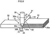
- the boundary part 25 may be cooled by a shielding gas supply device 51 supplying shielding gas 52 which is inert gas such as argon gas and helium gas to the boundary part 25 from the first or second outer surface F1, F2 side, when the first and second joining steps are performed.
- shielding gas 52 which is inert gas such as argon gas and helium gas
- the method of manufacturing the rotary electrical machine structure support of the second embodiment heat generated during the friction stir welding can be reduced, and accordingly the strength decrease of the boundary part 25 (joining object part) ascribable to the thermal effect can be made small. This enables the boundary part 25 where the first joining object member 32 and the second joining object member 31 are joined can have predetermined rigidity.
- FIG. 9 to FIG. 13 the same components as the components in the first embodiment illustrated in FIG. 2 , FIG. 4 and so on are denoted by the same reference signs, and redundant descriptions are not given.
- a pair of holding members 53, 54 is further arranged so as to hold the boundary part 25 between the first joining object member 32 and the second joining object member 31 whose end parts are in contact with each other, in the arrow P1, P2 directions from a third and a fourth outer surface F3, F4 side located on side surface sides of the first and second outer surfaces F1, F2.
- the pair of holding members 53, 54 is made of, for example or copper or a copper alloy.
- the rotary driven tool 30 is made to penetrate into the holding member 53 from the first or second outer surface F1, F2 side, and is slid (moved) onto the other holding member 54 along the interface 25a of the boundary part 25.
- the pair of joined holding members 53, 54 may be removed from the first and second joining object member 32, 31 sides.
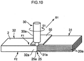
- a method of manufacturing a rotary electrical machine structure support illustrated in FIG. 10 can also be employed. Specifically, in the arranging step, as illustrated in FIG. 10 , a protective member 55 is further arranged on the first or second outer surface F1, F2 at the boundary part 25 between the first joining object member 32 and the second joining object member 31 whose end parts 32a, 31a are in contact with each other.
- the protective member 55 is a rectangular thin sheet with a thickness of 0.5 to 2 mm whose material is copper or a copper alloy. This protective member 55 is arranged to completely cover the boundary part 25 (a boundary line on the first or second outer surface F1, F2), with its longitudinal direction aligning in the sliding direction (the arrow B1 direction) of the tool 30.
- the protective member 55 is fixed at this position via a jig or the like. Further, the shorter-side length of the protective member 55 is equal to or more than the diameter of the shoulder part 30a of the tool 30. Further, the thickness of the protective member 55 is equal to or more than the dents which may be formed by the sliding of, for example, the end face of the shoulder part 30a of the tool 30 during the friction stir welding.
- the rotary driven tool 30 is made to penetrate into the boundary part 25 via the protective member 55 from the first or second outer surface F1, F2 side in the first and second joining steps. Then, the rotary driven tool 30 is slid (moved) along the interface 25a.
- the thickness of the protective member 55 can compensate for the thickness of the dents formed by the sliding of the shoulder part 30a of the tool 30, so that the boundary part 25 (joining object part) can have joining strength. Further, the occurrence of buckling or the like in the second joining object member (stack) 31 can be reduced.
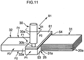
- the pair of holding members 53, 54 is arranged so as to hold the boundary part 25 between the first joining object member 32 and the second joining object member 31 whose end parts 32a, 31a are in contact with each other, from the third and fourth outer surface F3, F4 sides located on the side surface sides of the first and second outer surfaces F1, F2.
- a protective member 61 is further arranged on the pair of holding members 53, 54 and on the first or second outer surface F1, F2 of the boundary part 25 between the first joining object member 32 and the second joining object member 31.
- the rotary driven tool 30 is made to penetrate into the holding member 53 via the protective member 61 from the first or second outer surface F1, F2 side. Then, the rotary driven tool 30 is slid (moved) toward the other holding member 54 along the interface of the boundary part 25.
- the method of manufacturing the rotary electrical machine structure support illustrated in FIG. 11 described above it is possible to hinder the joining marks formed by the projecting part (penetration part) 30b of the tool 30 from remaining on the boundary part 25 and also prevent dispersion and so on of the plate materials 20a from the second joining object member 31. It is also possible to reduce the occurrence of the dents caused by the sliding of the shoulder part 30a of the tool 30. It is also possible to reduce the occurrence of the buckling and so on in the second joining object member (stack) 31.
- the pair of holding members 53, 54 and the protective member 61 which are arranged as illustrated in FIG. 11 may be integrated using friction stir welding (by providing joining parts 30e) as illustrated in FIG. 12 . This can improve workability when the pair of holding members 53, 54 and the protective member 61 are set.
- a joining auxiliary member 56 having a U-shaped cross section is arranged in the arranging step.
- the joining auxiliary member 56 includes: a pair of holding parts 56b, 56c having the function of the pair of holding members 53, 54 illustrated in FIG. 9 and FIG. 11 ; and a protective part 56a having the function of the protective members 55, 61 illustrated in FIG. 10 and FIG. 11 .
- the pair of holding parts 56b, 56c holds the boundary part 25 between the first joining object member 32 and the second joining object member 31 whose end parts 31a, 32a are in contact with each other, from the third and fourth outer surface F3, F4 sides located on the side surface sides of the first and second outer surfaces F1, F2.
- the protective part 56a is placed on the first or second outer surface F1, F2 of the boundary part 25. That is, the joining auxiliary member 56 has the structure in which the pair of holding members 53, 54 illustrated in FIG. 9 and FIG. 11 and the protective member 55 (or 61) illustrated in FIG. 10 and FIG. 11 are integrated.
- the rotary driven tool 30 is made to penetrate into the holding part 56b of the joining auxiliary member 56 from the first outer surface F1 side. Then, the rotary driven tool 30 is slid (moved) onto the protective part 56a and onto the other holding part 56c in sequence along the interface 25a of the boundary part 25.
- the friction stir welding using the tool 30 may be performed after, for example, the protective member 55 illustrated in FIG. 10 is arranged on the second outer surface F2.
- the method of manufacturing the rotary electrical machine structure support illustrated in FIG. 13 it is possible to hinder the joining marks formed by the projecting part (penetration part) 30b of the tool 30 from remaining on the boundary part 25 as previously described, and in addition, it is possible to prevent the dispersion and so on of the plate materials 20a from the second joining object member 31. Moreover, it is possible to reduce the occurrence of the dents caused by the sliding of the shoulder part 30a of the tool 30. It is also possible to reduce the occurrence of the buckling or the like in the second joining object member 31. Further, according to the method of manufacturing the rotary electrical machine structure support illustrated in FIG. 13 , the use of the joining auxiliary member 56 in which the protective part and the pair of holding parts are integrated can improve workability when the joining auxiliary member 56 is set.
- the second joining object member composed of the plural stacked and integrated plate materials and set thicker than the first joining object member in advance is joined to the first joining object member, and the excessive plate material of the second joining object member is removed after the joining.
- This can achieve strength high enough to endure vibration and strain while reducing the occurrence of defects, deformation, peeling, and breakage.
Landscapes
- Engineering & Computer Science (AREA)
- Power Engineering (AREA)
- Mechanical Engineering (AREA)
- Manufacturing & Machinery (AREA)
- Manufacture Of Motors, Generators (AREA)
- Pressure Welding/Diffusion-Bonding (AREA)
Abstract
Description
- Embodiments described herein relate generally to a method of manufacturing a rotary electrical machine structure support and a rotary electrical machine.
- In order to absorb strain ascribable to an internal stress generated by a centrifugal force, a rotor for a rotary electrical machine used in, for example, hydroelectric power generation includes a structure support in which a relatively hard solid member is joined to a flexible stack in which a plurality of thin plates are stacked and integrated.
- Such a structure support is fabricated as follows, for instance. The thin plates are first stacked and integrated, with their end parts being joined by TIG (Tungsten Inert Gas) welding, and after the end of the resultant stack is machined into a K-groove or the like, the stack machined to have the groove shape and the aforesaid solid member are further TIG-welded. As a material of the joining object members including the thin plates and so on which are to be TIG-welded, copper or a copper alloy is used.
- The aforesaid structure support needs to have mechanical strength high enough to endure vibration and strain generated by the centrifugal force. However, because of the use of a hardly weldable material such as the copper or the copper alloy as its material as described above, the support structure is likely to suffer defects at welded parts and its wide range is given a welding-time thermal effect which lowers strength of the base materials, and there is also a concern about its deformation after the welding, and peeling, breakage, and so on of the thin plates.
- Under such circumstances, problems to be solved by the present invention are to provide a method of manufacturing a rotary electrical machine structure support that can have mechanical strength high enough to endure vibration and strain while suffering less defects, deformation, peeling, and breakage, and to provide a rotary electrical machine.
-
-
FIG. 1 is a view schematically illustrating a cross section of a rotary electrical machine including a rotary electrical machine structure support according to a first embodiment. -
FIG. 2 is a perspective view illustrating a method of manufacturing the rotary electrical machine structure support inFIG. 1 , from a first outer surface side. -
FIG. 3 is a view illustrating the method of manufacturing the rotary electrical machine structure support inFIG. 1 , from a planar direction (upper surface direction). -
FIG. 4 is a perspective view illustrating the method of manufacturing the rotary electrical machine structure support inFIG. 1 , from a second outer surface side. -
FIG. 5 is a perspective view illustrating a method whose manufacturing steps are partly changed from those of the method of manufacturing the rotary electrical machine structure support inFIG. 2 . -
FIG. 6 is a perspective view illustrating a method whose manufacturing steps are partly changed from those of the methods of manufacturing the rotary electrical machine structure support inFIG. 2 andFIG. 5 . -
FIG. 7 is a perspective view illustrating a method of manufacturing a rotary electrical machine structure support according to a second embodiment, from the first outer surface side. -
FIG. 8 is a perspective view illustrating a method whose manufacturing steps are partly changed from those of the method of manufacturing the rotary electrical machine structure support inFIG. 7 . -
FIG. 9 is a perspective view illustrating a method of manufacturing a rotary electrical machine structure support according to a third embodiment, from a first outer surface side. -
FIG. 10 is a perspective view illustrating a method whose manufacturing steps are partly changed from those of the method of manufacturing the rotary electrical machine structure support inFIG. 9 . -
FIG. 11 is a perspective view illustrating a method whose manufacturing steps are partly changed from those of the methods of manufacturing the rotary electrical machine structure support inFIG. 9 andFIG. 10 . -
FIG. 12 is a view illustrating the method of manufacturing the rotary electrical machine structure support inFIG. 11 , from a planar direction (upper surface direction). -
FIG. 13 is a perspective view illustrating a method whose manufacturing steps are partly changed from those of the methods of manufacturing the rotary electrical machine structure support inFIG. 9 to FIG. 11 . - A method of manufacturing a rotary electrical machine structure support according to an embodiment includes an arranging step and a joining step. In the arranging step, a first joining object member and a second joining object member composed of a plurality of stacked and integrated plate materials and thicker than the first joining object member are arranged, with end parts of the first and second joining object members being in contact with each other. In the joining step, a tool which is rotary driven is made to penetrate into a boundary part between the first joining object member and the second joining object member whose end parts are in contact with each other, from a first outer surface side of the boundary part, and the tool is slid along an interface of the boundary part, whereby a rotary electrical machine structure support in which the first and second joining object members are joined to each other is obtained.
- Hereinafter, embodiments are described based on the drawings.
-
FIG. 1 illustrates a rotaryelectrical machine 10 including a rotary electricalmachine structure support 17 manufactured by a method of manufacturing a rotary electrical machine structure support of the present embodiment. As illustrated inFIG. 1 , the rotaryelectrical machine 10 is, for example, a variable-speed rotary electrical machine, and more specifically, for example, a variable-speed generator motor used for pumped-storage power generation and so on. - The rotary
electrical machine 10 includes astator 3, arotor 5, and so on. The rotaryelectrical machine 10 further includes cooling mechanisms symmetrically provided at both ends of arotation shaft 9 of therotor 5 respectively and each having, for example, afan 15 and an airflow duct, and so on. Therotation shaft 9 is supported by a structure part including thestator 3 via a bearing mechanism. Thestator 3 includes astator coil 12 and astator core 14. Therotor 5 includes arotor core 8 integrally provided with therotation shaft 9, androtor coils 7. - Here, the
rotor 5 includes the aforesaid rotary electricalmachine structure support 17 as illustrated inFIG. 1 so as to be capable of absorbing strain and vibration ascribable to an internal stress generated by a centrifugal force during the operation involving a speed change of the rotary electrical machine (variable-speed generator motor) 10. Specifically, as illustrated in later-describedFIG. 2 , the rotary electricalmachine structure support 17 is composed of a firstjoining object member 32 and a secondjoining object member 31 which are joined to each other, the firstjoining object member 32 having a rectangular parallelepiped solid structure and the secondjoining object member 31 being a flexible stack of a plurality of stacked and integrated plate materials (thin plates) 20a. The second joining object member (stack) 31 is composed of the stacked and integratedplate materials 20a each having a thickness of, for example, 0.25 mm and thus has, for example, a 20 mm thickness, which is thicker than the aforesaid first joiningobject member 32 by about 1 mm. - As illustrated in
FIG. 1 , the rotary electrical machine structure support 17 as described above is appropriately disposed at, for example, a place where the internal stress is likely to concentrate due to a structural reason when the centrifugal force acts on therotor 5. As materials of the first and second joining object members32, 31 forming the rotary electricalmachine structure support 17 as illustrated inFIG. 2 , copper or a copper alloy is used. Incidentally, aluminum or an aluminum alloy can also be used as the materials to form the first and second joiningobject members object member 31 which is the stack, a material having higher mechanical strength (for example, modulus of longitudinal elasticity) than that of the first joiningobject member 32 having the solid structure may be used. - Next, a method of manufacturing the rotary electrical machine structure support of the present embodiment that suitably achieves the joining of the first joining
object member 32 and the second joiningobject member 31 is described mainly based onFIG. 2 to FIG. 4 . The method of manufacturing the rotary electrical machine structure support of the present embodiment has an arranging step, a first joining step, and a second joining step. First, in the arranging step, as illustrated inFIG. 2 andFIG. 3 , the first joiningobject member 32 and the second joiningobject member 31 are arranged, with theirend parts object member 32 and the secondjoining object member 31 which are thus arranged are fixed on a predetermined processing board via, for example, a dedicated jig or the like. - A groove shape between the first joining
object member 32 and the second joiningobject member 31 which are joining targets is what is called an I groove (I-shape groove). That is, the whole end surfaces (opposed surfaces of theend parts object member 32 and the second joiningobject member 31, which are brought into direct contact with each other in the arranging step, are both flat surfaces. - Next, in the first joining step, as illustrated in
FIG. 2 andFIG. 3 , atool 30 rotary driven in the arrow S1 direction is made to penetrate into aboundary part 25 between the firstjoining object member 32 and the second joiningobject member 31 whoseend parts boundary part 25. Thereafter, the rotary driventool 30 is slid (moved) in the arrow B1 direction along aninterface 25a of theboundary part 25. - The
tool 30 is a joining tool in substantially a stepped columnar shape having a largediameter shoulder part 30a and a smalldiameter projecting part 30b provided at a tip side of theshoulder part 30a. Thetool 30 is movable in triaxial directions and rotates (is rotary driven) about the axial center of itself as a rotation center. The projectingpart 30b is a penetration part made to penetrate directly into the boundary part 25 (joiningobject parts part 30b is appropriately set in accordance with the penetration-direction thickness of theboundary part 25. - The operation of the
tool 30 is adjusted such that its rotation speed in the arrow S1 direction is, for example, 500 rpm to 1500 rpm, its moving speed in the arrow B1 direction is, for example, 17 cm/min to 30 cm/min, and a load with which the projectingpart 30b penetrates into theboundary part 25 becomes, for example, 3000 kgf to 5000 kgf. - Here, in the first joining step, as illustrated in
FIG. 2 andFIG. 3 , the boundary part 25 (the joiningobject part 30c) where the tool 30 (the projectingpart 30b) which rotates while sliding penetrates is softened by a generated frictional heat, and cured after base materials are kneaded by a generated plastic flow. As a result, the first outer surface F1 side (the joiningobject part 30c) at theboundary part 25 is friction-stir-welded (FSW). At this time, the second joiningobject member 31 set thicker by about 1 mm in advance is joined and thereafter an excessive portion of the stack is removed after the joining. This can prevent peeling and breakage occurring during the joining, at the same time. Here, in a case where the thickness of the second joiningobject member 31 is equal to or less than that of the first joiningobject member 32, there is a possibility that several pieces of surface layers of the stack peel to break during the friction stir welding and accordingly the second joiningobject member 31 comes to have a smaller sectional area than that of the firstjoining object member 32, leading to strength deficiency. - Next, in the second joining step, as illustrated in
FIG. 4 , the first joiningobject member 32 and the second joiningobject member 31 whose joiningobject part 30c has been friction-stir-welded are turned over so that a second outer surface F2 located on a rear surface side of the first outer surface F1 becomes an upper surface, and are fixed on the processing board via the aforesaid jig or the like. Further, in the second joining step, as illustrated inFIG. 4 , thetool 30 rotary driven in the arrow S1 direction is made to penetrate into the boundary part 25 (joiningobject part 30d) from the second outer surface F2 side of theboundary part 25. Then, the rotary driventool 30 is slid (moved) in the arrow B1 direction along theinterface 25a. As a result, the rotary electricalmachine structure support 17 in which the first and second joiningobject members tool 30 such as its rotation speed, its moving speed, and the load are adjusted as described above. That is, in the second joining step, as illustrated inFIG. 4 , the second outer surface F2 side (joiningobject part 30d) at theboundary part 25 is friction-stir-welded. - As is described above, the method of manufacturing the rotary electrical machine structure support of the present embodiment divides the friction stir welding of the first joining
object member 32 and the second joiningobject member 31 into two passes (two times) for the first outer surface F1 side and the second outer surface F2 side, and thus is capable of narrowing down the thermal effect range (softening region) where the boundary part 25 (base materials) is given the thermal effect due to the friction stirring. - Specifically, for example, when the friction stir welding of the
boundary part 25 is performed in one pass, theboundary part 25 is friction-stirred at a time in its whole thickness direction, and accordingly a tool having an increased size is used in consideration of, for example, rigidity, so that the thermal effect range is widened. On the other hand, in the method of manufacture of the present embodiment in which the friction stir welding of theboundary part 25 is divided into two passes, a tool having a reasonably small size is used in the two separate passes, enabling to narrow down the thermal effect range as a result. - Therefore, the method of manufacturing the rotary electrical machine structure support of the present embodiment can reduce a strength decrease ascribable to the thermal effect at the boundary part 25 (base materials) and can achieve the desired mechanical strength. Further, the method of manufacture of the present embodiment joins the first joining
object member 32 and the second joiningobject member 31 made of copper or a copper alloy which is a hardly weldable material, without using welding technology such as TIG welding (by using the friction stir welding which is a process suitable for joining hardly weldable materials and does not involve a melting phenomenon), enabling to reduce the occurrence of defects and deformations at the joining part. Further, the method of manufacture of the present embodiment eliminates a need for, for example, the machining of the joining part into the groove shape and preheating which are required in the welding, and thus can reduce a manufacturing cost. - Further, the rotary
electrical machine 10 whoserotor 5 includes the rotary electricalmachine structure support 17 manufactured in the above-described manner is capable of effectively absorbing the vibration and strain generated in therotor 5 by the centrifugal force during the operation involving a speed change. - Here, as illustrated in
FIG. 5 , the method of manufacturing the rotary electrical machine structure support of the present embodiment can also execute the friction stir welding, for example, while supplying the same material as the material of the first or second joiningobject member tool 30 slides. Specifically, as illustrated inFIG. 5 ,powder 34 of copper or a copper alloy is supplied from apowder supply device 33 during the friction stir welding from the first and second outer surface sides. Consequently, dents which are formed in the surfaces (upper surfaces) of the first and second joiningobject members shoulder part 30a of thetool 30 on the surfaces of the first and second joiningobject members - Further, as illustrated in
FIG. 6 , the method of manufacturing the rotary electrical machine structure support of the present embodiment is also capable of joiningend parts object members end parts 31a, 31b of the second joiningobject member 31 respectively by performing the arranging step and the first and second joining steps described above. - Next, a second embodiment is described based on
FIG. 7 andFIG. 8 . InFIG. 7 andFIG. 8 , the same components as the components in the first embodiment illustrated inFIG. 2 and so on are denoted by the same reference signs, and redundant descriptions are not given. - In a method of manufacturing a rotary electrical machine structure support of the present embodiment, the first and second joining steps are performed while at least the
boundary part 25 between the first joiningobject member 32 and the second joiningobject member 31 is cooled. The cooling in this case is achieved by, for example, bringing a cooling member in which a coolant flows into contact with the first and second joiningobject members - Specifically, as illustrated in
FIG. 7 , for example, the copper or copperalloy processing board 38, which is described in the first embodiment, where to fix the first and second joiningobject members coolant flow paths 39 where, for example, cooling water flows are formed inside theprocessing board 38. - Instead of the above, as illustrated in
FIG. 8 , theboundary part 25 may be cooled by a shieldinggas supply device 51 supplying shieldinggas 52 which is inert gas such as argon gas and helium gas to theboundary part 25 from the first or second outer surface F1, F2 side, when the first and second joining steps are performed. - Therefore, according to the method of manufacturing the rotary electrical machine structure support of the second embodiment, heat generated during the friction stir welding can be reduced, and accordingly the strength decrease of the boundary part 25 (joining object part) ascribable to the thermal effect can be made small. This enables the
boundary part 25 where the first joiningobject member 32 and the second joiningobject member 31 are joined can have predetermined rigidity. - Next, a third embodiment is described based on
FIG. 9 to FIG. 13 . InFIG. 9 to FIG. 13 , the same components as the components in the first embodiment illustrated inFIG. 2 ,FIG. 4 and so on are denoted by the same reference signs, and redundant descriptions are not given. - In a method of manufacturing a rotary electrical machine structure support of the present embodiment, as illustrated in
FIG. 9 , first in the arranging step, a pair of holdingmembers boundary part 25 between the first joiningobject member 32 and the second joiningobject member 31 whose end parts are in contact with each other, in the arrow P1, P2 directions from a third and a fourth outer surface F3, F4 side located on side surface sides of the first and second outer surfaces F1, F2. The pair of holdingmembers - Further, in the first and second joining steps, as illustrated in
FIG. 9 , the rotary driventool 30 is made to penetrate into the holdingmember 53 from the first or second outer surface F1, F2 side, and is slid (moved) onto the other holdingmember 54 along theinterface 25a of theboundary part 25. - According to this method of manufacture, it is possible to hinder joining marks formed by the projecting part (penetration part) 30b of the
tool 30 during the friction stir welding from remaining on the surface (upper surface) of theboundary part 25, and in addition, it is possible to prevent theplate materials 20a from separating from the main body of the second joiningobject member 31. Incidentally, after the joining of theboundary part 25, the pair of joined holdingmembers object member - Besides, a method of manufacturing a rotary electrical machine structure support illustrated in
FIG. 10 can also be employed. Specifically, in the arranging step, as illustrated inFIG. 10 , aprotective member 55 is further arranged on the first or second outer surface F1, F2 at theboundary part 25 between the first joiningobject member 32 and the second joiningobject member 31 whoseend parts - The
protective member 55 is a rectangular thin sheet with a thickness of 0.5 to 2 mm whose material is copper or a copper alloy. Thisprotective member 55 is arranged to completely cover the boundary part 25 (a boundary line on the first or second outer surface F1, F2), with its longitudinal direction aligning in the sliding direction (the arrow B1 direction) of thetool 30. Theprotective member 55 is fixed at this position via a jig or the like. Further, the shorter-side length of theprotective member 55 is equal to or more than the diameter of theshoulder part 30a of thetool 30. Further, the thickness of theprotective member 55 is equal to or more than the dents which may be formed by the sliding of, for example, the end face of theshoulder part 30a of thetool 30 during the friction stir welding. - After the
protective member 55 as described above is arranged, the rotary driventool 30 is made to penetrate into theboundary part 25 via theprotective member 55 from the first or second outer surface F1, F2 side in the first and second joining steps. Then, the rotary driventool 30 is slid (moved) along theinterface 25a. According to the method of manufacture as described above, the thickness of theprotective member 55 can compensate for the thickness of the dents formed by the sliding of theshoulder part 30a of thetool 30, so that the boundary part 25 (joining object part) can have joining strength. Further, the occurrence of buckling or the like in the second joining object member (stack) 31 can be reduced. - It is also possible to employ a method of manufacturing a rotary electrical machine structure support illustrated in
FIG. 11 . Specifically, as illustrated inFIG. 11 , in the arranging step, the pair of holdingmembers boundary part 25 between the first joiningobject member 32 and the second joiningobject member 31 whoseend parts protective member 61 is further arranged on the pair of holdingmembers boundary part 25 between the first joiningobject member 32 and the second joiningobject member 31. - Further, in the first and second joining steps, the rotary driven
tool 30 is made to penetrate into the holdingmember 53 via theprotective member 61 from the first or second outer surface F1, F2 side. Then, the rotary driventool 30 is slid (moved) toward the other holdingmember 54 along the interface of theboundary part 25. - According to the method of manufacturing the rotary electrical machine structure support illustrated in
FIG. 11 described above, it is possible to hinder the joining marks formed by the projecting part (penetration part) 30b of thetool 30 from remaining on theboundary part 25 and also prevent dispersion and so on of theplate materials 20a from the second joiningobject member 31. It is also possible to reduce the occurrence of the dents caused by the sliding of theshoulder part 30a of thetool 30. It is also possible to reduce the occurrence of the buckling and so on in the second joining object member (stack) 31. - Here, in the arranging step, the pair of holding
members protective member 61 which are arranged as illustrated inFIG. 11 may be integrated using friction stir welding (by providing joiningparts 30e) as illustrated inFIG. 12 . This can improve workability when the pair of holdingmembers protective member 61 are set. - Instead of the above method of manufacture, it is also possible to employ a method of manufacturing a rotary electrical machine structure support illustrated in
FIG. 13 . Specifically, in the arranging step, as illustrated inFIG. 13 , a joiningauxiliary member 56 having a U-shaped cross section is arranged. The joiningauxiliary member 56 includes: a pair of holdingparts members FIG. 9 andFIG. 11 ; and aprotective part 56a having the function of theprotective members FIG. 10 andFIG. 11 . - As illustrated in
FIG. 13 , the pair of holdingparts boundary part 25 between the first joiningobject member 32 and the second joiningobject member 31 whoseend parts protective part 56a is placed on the first or second outer surface F1, F2 of theboundary part 25. That is, the joiningauxiliary member 56 has the structure in which the pair of holdingmembers FIG. 9 andFIG. 11 and the protective member 55 (or 61) illustrated inFIG. 10 andFIG. 11 are integrated. - In a case where at least the first joining step is performed after the joining
auxiliary member 56 as described above is arranged, the rotary driventool 30 is made to penetrate into the holdingpart 56b of the joiningauxiliary member 56 from the first outer surface F1 side. Then, the rotary driventool 30 is slid (moved) onto theprotective part 56a and onto the other holdingpart 56c in sequence along theinterface 25a of theboundary part 25. Incidentally, in a case where the second joining step is performed, the friction stir welding using thetool 30 may be performed after, for example, theprotective member 55 illustrated inFIG. 10 is arranged on the second outer surface F2. - According to the method of manufacturing the rotary electrical machine structure support illustrated in
FIG. 13 , it is possible to hinder the joining marks formed by the projecting part (penetration part) 30b of thetool 30 from remaining on theboundary part 25 as previously described, and in addition, it is possible to prevent the dispersion and so on of theplate materials 20a from the second joiningobject member 31. Moreover, it is possible to reduce the occurrence of the dents caused by the sliding of theshoulder part 30a of thetool 30. It is also possible to reduce the occurrence of the buckling or the like in the second joiningobject member 31. Further, according to the method of manufacturing the rotary electrical machine structure support illustrated inFIG. 13 , the use of the joiningauxiliary member 56 in which the protective part and the pair of holding parts are integrated can improve workability when the joiningauxiliary member 56 is set. - According to at least one of the embodiments described above, the second joining object member composed of the plural stacked and integrated plate materials and set thicker than the first joining object member in advance is joined to the first joining object member, and the excessive plate material of the second joining object member is removed after the joining. This can achieve strength high enough to endure vibration and strain while reducing the occurrence of defects, deformation, peeling, and breakage.
- While certain embodiments have been described, these embodiments have been presented by way of example only, and are not intended to limit the scope of the inventions. Indeed, the novel embodiments described herein may be embodied in a variety of other forms; furthermore, various omissions, substitutions and changes in the form of the embodiments described herein may be made without departing from the spirit of the inventions. The accompanying claims and their equivalents are intended to cover such forms or modifications as would fall within the scope and spirit of the inventions.
Claims (5)
- A method of manufacturing a rotary electrical machine structure support, the method comprising:an arranging step of arranging a first joining object member and a second joining object member composed of a plurality of stacked and integrated plate materials and thicker than the first joining object member, with end parts of the first and second joining object members being in contact with each other; anda joining step of making a tool which is rotary driven penetrate into a boundary part between the first joining object member and the second joining object member whose end parts are in contact with each other, from a first outer surface side of the boundary part, and sliding the tool along an interface of the boundary part.
- The method of manufacturing the rotary electrical machine structure support according to claim 1, wherein the joining step is performed while the same material as a material of the first or second joining object member is supplied onto a moving path where the rotary driven tool slides.
- The method of manufacturing the rotary electrical machine structure support according to claim 1 or claim 2,
wherein, in the arranging step, a pair of holding members is further arranged so as to hold the boundary part between the first joining object member and the second joining object member whose end parts are in contact with each other, from third and fourth outer surface sides located on side surface sides of the first and second outer surfaces, and
wherein, in the joining step, the rotary driven tool made to penetrate into one of the holding members from the first or second outer surface side is slid onto the other holding member along the interface of the boundary part. - The method of manufacturing the rotary electrical machine structure support according to any one of claims 1 to 3,
wherein, in the arranging step, a protective member is further arranged on the first or second outer surface of the boundary part between the first joining object member and the second joining object member whose end parts are in contact with each other, and
wherein, in the joining step, the rotary driven tool made to penetrate into the boundary part via the protective member from the first or second outer surface side is slid along the interface. - A rotary electrical machine comprising the rotary electrical machine structure support manufactured by the method of manufacturing the rotary electrical machine structure support according to any one of claims 1 to 4.
Applications Claiming Priority (1)
| Application Number | Priority Date | Filing Date | Title |
|---|---|---|---|
| JP2015205683A JP2017077565A (en) | 2015-10-19 | 2015-10-19 | Method for manufacturing structure support for rotary electric machine, and rotary electric machine |
Publications (2)
| Publication Number | Publication Date |
|---|---|
| EP3166211A1 true EP3166211A1 (en) | 2017-05-10 |
| EP3166211B1 EP3166211B1 (en) | 2019-06-12 |
Family
ID=57348444
Family Applications (1)
| Application Number | Title | Priority Date | Filing Date |
|---|---|---|---|
| EP16194482.2A Active EP3166211B1 (en) | 2015-10-19 | 2016-10-18 | Method of manufacturing rotary electrical machine structure support and rotary electrical machine |
Country Status (4)
| Country | Link |
|---|---|
| US (1) | US20170110940A1 (en) |
| EP (1) | EP3166211B1 (en) |
| JP (1) | JP2017077565A (en) |
| CN (1) | CN106911236B (en) |
Cited By (1)
| Publication number | Priority date | Publication date | Assignee | Title |
|---|---|---|---|---|
| US20200016825A1 (en) * | 2018-07-16 | 2020-01-16 | National Chung Cheng University | Additive manufacturing method |
Families Citing this family (5)
| Publication number | Priority date | Publication date | Assignee | Title |
|---|---|---|---|---|
| DE102015015762A1 (en) * | 2015-12-01 | 2017-06-01 | Kienle + Spiess Gmbh | Method for producing a lamellar packet consisting of superimposed lamellae and device for carrying out such a method |
| CN110076442A (en) * | 2019-04-28 | 2019-08-02 | 深圳市华盛源机电有限公司 | The processing technology and tooling of copper sheet flexible joining part friction welding (FW) |
| CN110091050A (en) * | 2019-05-10 | 2019-08-06 | 无锡市晟锋金属材料有限公司 | A kind of soft hardwired welding method of copper material in special shape |
| CN111872540A (en) * | 2020-07-06 | 2020-11-03 | 东莞市源阳热能科技有限公司 | Water-cooling plate welding process and clamp for welding water-cooling plate |
| JP7452496B2 (en) * | 2021-06-07 | 2024-03-19 | 日本軽金属株式会社 | Bonded body manufacturing method and bonding device |
Citations (3)
| Publication number | Priority date | Publication date | Assignee | Title |
|---|---|---|---|---|
| EP1825946A1 (en) * | 2006-02-27 | 2007-08-29 | Hitachi, Ltd. | Friction stir welding method of two members having different thicknesses |
| CN102873454A (en) * | 2012-09-18 | 2013-01-16 | 西北工业大学 | Welding method for multi-layer metal strip |
| EP2913908A2 (en) * | 2014-02-27 | 2015-09-02 | Kabushiki Kaisha Toshiba | Method of manufacturing a rotor coil and corresponding rotary electrical machine |
Family Cites Families (5)
| Publication number | Priority date | Publication date | Assignee | Title |
|---|---|---|---|---|
| JP3070735B2 (en) * | 1997-07-23 | 2000-07-31 | 株式会社日立製作所 | Friction stir welding method |
| CN100553851C (en) * | 2001-03-07 | 2009-10-28 | 昭和电工株式会社 | Friction agitation joining method and method for manufacturing joined butted members |
| JP4875718B2 (en) * | 2009-01-21 | 2012-02-15 | 株式会社井上製作所 | Flexible conductor and method for producing flexible conductor |
| JP5514782B2 (en) * | 2010-09-24 | 2014-06-04 | 株式会社Uacj | Rotational welding tool for friction stir welding, and friction stir welding method using the same |
| JP2014045545A (en) * | 2012-08-24 | 2014-03-13 | Toshiba Corp | Rotor, rotary electric machine, and generator for geothermal power |
-
2015
- 2015-10-19 JP JP2015205683A patent/JP2017077565A/en active Pending
-
2016
- 2016-10-12 US US15/291,307 patent/US20170110940A1/en not_active Abandoned
- 2016-10-18 EP EP16194482.2A patent/EP3166211B1/en active Active
- 2016-10-19 CN CN201610910989.9A patent/CN106911236B/en active Active
Patent Citations (3)
| Publication number | Priority date | Publication date | Assignee | Title |
|---|---|---|---|---|
| EP1825946A1 (en) * | 2006-02-27 | 2007-08-29 | Hitachi, Ltd. | Friction stir welding method of two members having different thicknesses |
| CN102873454A (en) * | 2012-09-18 | 2013-01-16 | 西北工业大学 | Welding method for multi-layer metal strip |
| EP2913908A2 (en) * | 2014-02-27 | 2015-09-02 | Kabushiki Kaisha Toshiba | Method of manufacturing a rotor coil and corresponding rotary electrical machine |
Cited By (2)
| Publication number | Priority date | Publication date | Assignee | Title |
|---|---|---|---|---|
| US20200016825A1 (en) * | 2018-07-16 | 2020-01-16 | National Chung Cheng University | Additive manufacturing method |
| US10814548B2 (en) * | 2018-07-16 | 2020-10-27 | National Chung Cheng University | Additive manufacturing method |
Also Published As
| Publication number | Publication date |
|---|---|
| US20170110940A1 (en) | 2017-04-20 |
| JP2017077565A (en) | 2017-04-27 |
| CN106911236B (en) | 2019-07-05 |
| EP3166211B1 (en) | 2019-06-12 |
| CN106911236A (en) | 2017-06-30 |
Similar Documents
| Publication | Publication Date | Title |
|---|---|---|
| EP3166211B1 (en) | Method of manufacturing rotary electrical machine structure support and rotary electrical machine | |
| EP2913908A2 (en) | Method of manufacturing a rotor coil and corresponding rotary electrical machine | |
| CN102672358B (en) | Welding apparatus for induction motor | |
| US11349378B2 (en) | Coil segment cutting method and coil segment cutting apparatus | |
| EP2375082A2 (en) | Motor-driven centrifugal compressor | |
| JP5435468B2 (en) | Friction stir welding apparatus and friction stir welding method | |
| CN206775256U (en) | Rotor component, rotor and motor | |
| KR101504844B1 (en) | Device for cutting metal plate | |
| JP2011036917A (en) | Friction welding method | |
| US20190109500A1 (en) | Method of manufacturing statore core, and stator core | |
| JP2019033595A (en) | Iron core manufacturing device, iron core manufacturing method | |
| WO2015033537A1 (en) | Indirect spot welding device | |
| CN112453687A (en) | Stator core lamination group batch welding tool based on laser welding | |
| JP2016107302A (en) | Method for manufacturing rotary electrical machine structure support, and rotary electrical machine | |
| US20190068014A1 (en) | Rotor and rotating electrical machine | |
| US20210241973A1 (en) | Laminated core, electric machine, transformer and method for producing a laminated core | |
| EP4501528A1 (en) | Welding apparatus | |
| CN101673989B (en) | Precise coreless cup direct-current deceleration motor | |
| CN115395745B (en) | Rotor manufacturing equipment | |
| KR20150056718A (en) | Device and method for friction stir welding | |
| TWI871374B (en) | Rotor assembly for an axial flux machine and method for improving a rotor of an axial flux machine | |
| KR20160052895A (en) | Welding method and jig device of eletron beam welder for various circular path welding | |
| JP6117025B2 (en) | Manufacturing method of laminated iron core | |
| JP2012210070A (en) | Rotor of motor and method for manufacturing the same | |
| CN103128864A (en) | Thrust bearing and motorized spindle |
Legal Events
| Date | Code | Title | Description |
|---|---|---|---|
| PUAI | Public reference made under article 153(3) epc to a published international application that has entered the european phase |
Free format text: ORIGINAL CODE: 0009012 |
|
| STAA | Information on the status of an ep patent application or granted ep patent |
Free format text: STATUS: REQUEST FOR EXAMINATION WAS MADE |
|
| 17P | Request for examination filed |
Effective date: 20161018 |
|
| AK | Designated contracting states |
Kind code of ref document: A1 Designated state(s): AL AT BE BG CH CY CZ DE DK EE ES FI FR GB GR HR HU IE IS IT LI LT LU LV MC MK MT NL NO PL PT RO RS SE SI SK SM TR |
|
| AX | Request for extension of the european patent |
Extension state: BA ME |
|
| STAA | Information on the status of an ep patent application or granted ep patent |
Free format text: STATUS: EXAMINATION IS IN PROGRESS |
|
| 17Q | First examination report despatched |
Effective date: 20180206 |
|
| RIC1 | Information provided on ipc code assigned before grant |
Ipc: H02K 3/51 20060101ALI20181004BHEP Ipc: H02K 3/50 20060101AFI20181004BHEP Ipc: B23K 103/16 20060101ALN20181004BHEP Ipc: B23K 20/12 20060101ALI20181004BHEP Ipc: H02K 15/02 20060101ALI20181004BHEP |
|
| GRAP | Despatch of communication of intention to grant a patent |
Free format text: ORIGINAL CODE: EPIDOSNIGR1 |
|
| STAA | Information on the status of an ep patent application or granted ep patent |
Free format text: STATUS: GRANT OF PATENT IS INTENDED |
|
| RIC1 | Information provided on ipc code assigned before grant |
Ipc: B23K 103/12 20060101ALN20181203BHEP Ipc: B23K 20/12 20060101ALI20181203BHEP Ipc: H02K 15/02 20060101ALI20181203BHEP Ipc: H02K 3/51 20060101ALI20181203BHEP Ipc: H02K 3/50 20060101AFI20181203BHEP |
|
| INTG | Intention to grant announced |
Effective date: 20181218 |
|
| GRAS | Grant fee paid |
Free format text: ORIGINAL CODE: EPIDOSNIGR3 |
|
| GRAA | (expected) grant |
Free format text: ORIGINAL CODE: 0009210 |
|
| STAA | Information on the status of an ep patent application or granted ep patent |
Free format text: STATUS: THE PATENT HAS BEEN GRANTED |
|
| AK | Designated contracting states |
Kind code of ref document: B1 Designated state(s): AL AT BE BG CH CY CZ DE DK EE ES FI FR GB GR HR HU IE IS IT LI LT LU LV MC MK MT NL NO PL PT RO RS SE SI SK SM TR |
|
| REG | Reference to a national code |
Ref country code: GB Ref legal event code: FG4D |
|
| REG | Reference to a national code |
Ref country code: CH Ref legal event code: EP |
|
| REG | Reference to a national code |
Ref country code: AT Ref legal event code: REF Ref document number: 1143874 Country of ref document: AT Kind code of ref document: T Effective date: 20190615 |
|
| REG | Reference to a national code |
Ref country code: DE Ref legal event code: R096 Ref document number: 602016015089 Country of ref document: DE |
|
| REG | Reference to a national code |
Ref country code: IE Ref legal event code: FG4D |
|
| REG | Reference to a national code |
Ref country code: NL Ref legal event code: MP Effective date: 20190612 |
|
| REG | Reference to a national code |
Ref country code: LT Ref legal event code: MG4D |
|
| PG25 | Lapsed in a contracting state [announced via postgrant information from national office to epo] |
Ref country code: FI Free format text: LAPSE BECAUSE OF FAILURE TO SUBMIT A TRANSLATION OF THE DESCRIPTION OR TO PAY THE FEE WITHIN THE PRESCRIBED TIME-LIMIT Effective date: 20190612 Ref country code: AL Free format text: LAPSE BECAUSE OF FAILURE TO SUBMIT A TRANSLATION OF THE DESCRIPTION OR TO PAY THE FEE WITHIN THE PRESCRIBED TIME-LIMIT Effective date: 20190612 Ref country code: HR Free format text: LAPSE BECAUSE OF FAILURE TO SUBMIT A TRANSLATION OF THE DESCRIPTION OR TO PAY THE FEE WITHIN THE PRESCRIBED TIME-LIMIT Effective date: 20190612 Ref country code: NO Free format text: LAPSE BECAUSE OF FAILURE TO SUBMIT A TRANSLATION OF THE DESCRIPTION OR TO PAY THE FEE WITHIN THE PRESCRIBED TIME-LIMIT Effective date: 20190912 Ref country code: SE Free format text: LAPSE BECAUSE OF FAILURE TO SUBMIT A TRANSLATION OF THE DESCRIPTION OR TO PAY THE FEE WITHIN THE PRESCRIBED TIME-LIMIT Effective date: 20190612 Ref country code: LT Free format text: LAPSE BECAUSE OF FAILURE TO SUBMIT A TRANSLATION OF THE DESCRIPTION OR TO PAY THE FEE WITHIN THE PRESCRIBED TIME-LIMIT Effective date: 20190612 |
|
| PG25 | Lapsed in a contracting state [announced via postgrant information from national office to epo] |
Ref country code: LV Free format text: LAPSE BECAUSE OF FAILURE TO SUBMIT A TRANSLATION OF THE DESCRIPTION OR TO PAY THE FEE WITHIN THE PRESCRIBED TIME-LIMIT Effective date: 20190612 Ref country code: RS Free format text: LAPSE BECAUSE OF FAILURE TO SUBMIT A TRANSLATION OF THE DESCRIPTION OR TO PAY THE FEE WITHIN THE PRESCRIBED TIME-LIMIT Effective date: 20190612 Ref country code: BG Free format text: LAPSE BECAUSE OF FAILURE TO SUBMIT A TRANSLATION OF THE DESCRIPTION OR TO PAY THE FEE WITHIN THE PRESCRIBED TIME-LIMIT Effective date: 20190912 Ref country code: GR Free format text: LAPSE BECAUSE OF FAILURE TO SUBMIT A TRANSLATION OF THE DESCRIPTION OR TO PAY THE FEE WITHIN THE PRESCRIBED TIME-LIMIT Effective date: 20190913 |
|
| PG25 | Lapsed in a contracting state [announced via postgrant information from national office to epo] |
Ref country code: CZ Free format text: LAPSE BECAUSE OF FAILURE TO SUBMIT A TRANSLATION OF THE DESCRIPTION OR TO PAY THE FEE WITHIN THE PRESCRIBED TIME-LIMIT Effective date: 20190612 Ref country code: PT Free format text: LAPSE BECAUSE OF FAILURE TO SUBMIT A TRANSLATION OF THE DESCRIPTION OR TO PAY THE FEE WITHIN THE PRESCRIBED TIME-LIMIT Effective date: 20191014 Ref country code: SK Free format text: LAPSE BECAUSE OF FAILURE TO SUBMIT A TRANSLATION OF THE DESCRIPTION OR TO PAY THE FEE WITHIN THE PRESCRIBED TIME-LIMIT Effective date: 20190612 Ref country code: NL Free format text: LAPSE BECAUSE OF FAILURE TO SUBMIT A TRANSLATION OF THE DESCRIPTION OR TO PAY THE FEE WITHIN THE PRESCRIBED TIME-LIMIT Effective date: 20190612 Ref country code: EE Free format text: LAPSE BECAUSE OF FAILURE TO SUBMIT A TRANSLATION OF THE DESCRIPTION OR TO PAY THE FEE WITHIN THE PRESCRIBED TIME-LIMIT Effective date: 20190612 Ref country code: RO Free format text: LAPSE BECAUSE OF FAILURE TO SUBMIT A TRANSLATION OF THE DESCRIPTION OR TO PAY THE FEE WITHIN THE PRESCRIBED TIME-LIMIT Effective date: 20190612 |
|
| PG25 | Lapsed in a contracting state [announced via postgrant information from national office to epo] |
Ref country code: IT Free format text: LAPSE BECAUSE OF FAILURE TO SUBMIT A TRANSLATION OF THE DESCRIPTION OR TO PAY THE FEE WITHIN THE PRESCRIBED TIME-LIMIT Effective date: 20190612 Ref country code: IS Free format text: LAPSE BECAUSE OF FAILURE TO SUBMIT A TRANSLATION OF THE DESCRIPTION OR TO PAY THE FEE WITHIN THE PRESCRIBED TIME-LIMIT Effective date: 20191012 Ref country code: ES Free format text: LAPSE BECAUSE OF FAILURE TO SUBMIT A TRANSLATION OF THE DESCRIPTION OR TO PAY THE FEE WITHIN THE PRESCRIBED TIME-LIMIT Effective date: 20190612 Ref country code: SM Free format text: LAPSE BECAUSE OF FAILURE TO SUBMIT A TRANSLATION OF THE DESCRIPTION OR TO PAY THE FEE WITHIN THE PRESCRIBED TIME-LIMIT Effective date: 20190612 |
|
| REG | Reference to a national code |
Ref country code: DE Ref legal event code: R097 Ref document number: 602016015089 Country of ref document: DE |
|
| PG25 | Lapsed in a contracting state [announced via postgrant information from national office to epo] |
Ref country code: TR Free format text: LAPSE BECAUSE OF FAILURE TO SUBMIT A TRANSLATION OF THE DESCRIPTION OR TO PAY THE FEE WITHIN THE PRESCRIBED TIME-LIMIT Effective date: 20190612 |
|
| PLBE | No opposition filed within time limit |
Free format text: ORIGINAL CODE: 0009261 |
|
| STAA | Information on the status of an ep patent application or granted ep patent |
Free format text: STATUS: NO OPPOSITION FILED WITHIN TIME LIMIT |
|
| PG25 | Lapsed in a contracting state [announced via postgrant information from national office to epo] |
Ref country code: PL Free format text: LAPSE BECAUSE OF FAILURE TO SUBMIT A TRANSLATION OF THE DESCRIPTION OR TO PAY THE FEE WITHIN THE PRESCRIBED TIME-LIMIT Effective date: 20190612 Ref country code: DK Free format text: LAPSE BECAUSE OF FAILURE TO SUBMIT A TRANSLATION OF THE DESCRIPTION OR TO PAY THE FEE WITHIN THE PRESCRIBED TIME-LIMIT Effective date: 20190612 |
|
| 26N | No opposition filed |
Effective date: 20200313 |
|
| PG25 | Lapsed in a contracting state [announced via postgrant information from national office to epo] |
Ref country code: SI Free format text: LAPSE BECAUSE OF FAILURE TO SUBMIT A TRANSLATION OF THE DESCRIPTION OR TO PAY THE FEE WITHIN THE PRESCRIBED TIME-LIMIT Effective date: 20190612 Ref country code: IS Free format text: LAPSE BECAUSE OF FAILURE TO SUBMIT A TRANSLATION OF THE DESCRIPTION OR TO PAY THE FEE WITHIN THE PRESCRIBED TIME-LIMIT Effective date: 20200224 Ref country code: MC Free format text: LAPSE BECAUSE OF FAILURE TO SUBMIT A TRANSLATION OF THE DESCRIPTION OR TO PAY THE FEE WITHIN THE PRESCRIBED TIME-LIMIT Effective date: 20190612 |
|
| REG | Reference to a national code |
Ref country code: CH Ref legal event code: PL |
|
| PG2D | Information on lapse in contracting state deleted |
Ref country code: IS |
|
| PG25 | Lapsed in a contracting state [announced via postgrant information from national office to epo] |
Ref country code: LI Free format text: LAPSE BECAUSE OF NON-PAYMENT OF DUE FEES Effective date: 20191031 Ref country code: LU Free format text: LAPSE BECAUSE OF NON-PAYMENT OF DUE FEES Effective date: 20191018 Ref country code: CH Free format text: LAPSE BECAUSE OF NON-PAYMENT OF DUE FEES Effective date: 20191031 |
|
| REG | Reference to a national code |
Ref country code: BE Ref legal event code: MM Effective date: 20191031 |
|
| PG25 | Lapsed in a contracting state [announced via postgrant information from national office to epo] |
Ref country code: BE Free format text: LAPSE BECAUSE OF NON-PAYMENT OF DUE FEES Effective date: 20191031 |
|
| PG25 | Lapsed in a contracting state [announced via postgrant information from national office to epo] |
Ref country code: IE Free format text: LAPSE BECAUSE OF NON-PAYMENT OF DUE FEES Effective date: 20191018 |
|
| PG25 | Lapsed in a contracting state [announced via postgrant information from national office to epo] |
Ref country code: CY Free format text: LAPSE BECAUSE OF FAILURE TO SUBMIT A TRANSLATION OF THE DESCRIPTION OR TO PAY THE FEE WITHIN THE PRESCRIBED TIME-LIMIT Effective date: 20190612 |
|
| GBPC | Gb: european patent ceased through non-payment of renewal fee |
Effective date: 20201018 |
|
| PG25 | Lapsed in a contracting state [announced via postgrant information from national office to epo] |
Ref country code: HU Free format text: LAPSE BECAUSE OF FAILURE TO SUBMIT A TRANSLATION OF THE DESCRIPTION OR TO PAY THE FEE WITHIN THE PRESCRIBED TIME-LIMIT; INVALID AB INITIO Effective date: 20161018 Ref country code: MT Free format text: LAPSE BECAUSE OF FAILURE TO SUBMIT A TRANSLATION OF THE DESCRIPTION OR TO PAY THE FEE WITHIN THE PRESCRIBED TIME-LIMIT Effective date: 20190612 |
|
| PG25 | Lapsed in a contracting state [announced via postgrant information from national office to epo] |
Ref country code: GB Free format text: LAPSE BECAUSE OF NON-PAYMENT OF DUE FEES Effective date: 20201018 |
|
| REG | Reference to a national code |
Ref country code: AT Ref legal event code: UEP Ref document number: 1143874 Country of ref document: AT Kind code of ref document: T Effective date: 20190612 |
|
| PG25 | Lapsed in a contracting state [announced via postgrant information from national office to epo] |
Ref country code: MK Free format text: LAPSE BECAUSE OF FAILURE TO SUBMIT A TRANSLATION OF THE DESCRIPTION OR TO PAY THE FEE WITHIN THE PRESCRIBED TIME-LIMIT Effective date: 20190612 |
|
| PGFP | Annual fee paid to national office [announced via postgrant information from national office to epo] |
Ref country code: FR Payment date: 20250821 Year of fee payment: 10 |
|
| PGFP | Annual fee paid to national office [announced via postgrant information from national office to epo] |
Ref country code: DE Payment date: 20250827 Year of fee payment: 10 |
|
| PGFP | Annual fee paid to national office [announced via postgrant information from national office to epo] |
Ref country code: AT Payment date: 20250925 Year of fee payment: 10 |