EP3166083A2 - Superimposed display method and superimposed display apparatus - Google Patents
Superimposed display method and superimposed display apparatus Download PDFInfo
- Publication number
- EP3166083A2 EP3166083A2 EP16194556.3A EP16194556A EP3166083A2 EP 3166083 A2 EP3166083 A2 EP 3166083A2 EP 16194556 A EP16194556 A EP 16194556A EP 3166083 A2 EP3166083 A2 EP 3166083A2
- Authority
- EP
- European Patent Office
- Prior art keywords
- image
- model
- shot
- line
- ridge
- Prior art date
- Legal status (The legal status is an assumption and is not a legal conclusion. Google has not performed a legal analysis and makes no representation as to the accuracy of the status listed.)
- Granted
Links
Images










Classifications
-
- G—PHYSICS
- G06—COMPUTING OR CALCULATING; COUNTING
- G06T—IMAGE DATA PROCESSING OR GENERATION, IN GENERAL
- G06T3/00—Geometric image transformations in the plane of the image
- G06T3/14—Transformations for image registration, e.g. adjusting or mapping for alignment of images
- G06T3/147—Transformations for image registration, e.g. adjusting or mapping for alignment of images using affine transformations
-
- G—PHYSICS
- G06—COMPUTING OR CALCULATING; COUNTING
- G06T—IMAGE DATA PROCESSING OR GENERATION, IN GENERAL
- G06T19/00—Manipulating three-dimensional [3D] models or images for computer graphics
- G06T19/003—Navigation within 3D models or images
-
- G—PHYSICS
- G06—COMPUTING OR CALCULATING; COUNTING
- G06T—IMAGE DATA PROCESSING OR GENERATION, IN GENERAL
- G06T17/00—Three-dimensional [3D] modelling for computer graphics
-
- G—PHYSICS
- G06—COMPUTING OR CALCULATING; COUNTING
- G06T—IMAGE DATA PROCESSING OR GENERATION, IN GENERAL
- G06T19/00—Manipulating three-dimensional [3D] models or images for computer graphics
- G06T19/006—Mixed reality
-
- G—PHYSICS
- G06—COMPUTING OR CALCULATING; COUNTING
- G06T—IMAGE DATA PROCESSING OR GENERATION, IN GENERAL
- G06T19/00—Manipulating three-dimensional [3D] models or images for computer graphics
- G06T19/20—Editing of three-dimensional [3D] images, e.g. changing shapes or colours, aligning objects or positioning parts
-
- G—PHYSICS
- G06—COMPUTING OR CALCULATING; COUNTING
- G06T—IMAGE DATA PROCESSING OR GENERATION, IN GENERAL
- G06T7/00—Image analysis
- G06T7/0002—Inspection of images, e.g. flaw detection
- G06T7/0004—Industrial image inspection
- G06T7/001—Industrial image inspection using an image reference approach
-
- G—PHYSICS
- G06—COMPUTING OR CALCULATING; COUNTING
- G06T—IMAGE DATA PROCESSING OR GENERATION, IN GENERAL
- G06T2207/00—Indexing scheme for image analysis or image enhancement
- G06T2207/10—Image acquisition modality
- G06T2207/10004—Still image; Photographic image
-
- G—PHYSICS
- G06—COMPUTING OR CALCULATING; COUNTING
- G06T—IMAGE DATA PROCESSING OR GENERATION, IN GENERAL
- G06T2207/00—Indexing scheme for image analysis or image enhancement
- G06T2207/20—Special algorithmic details
- G06T2207/20092—Interactive image processing based on input by user
-
- G—PHYSICS
- G06—COMPUTING OR CALCULATING; COUNTING
- G06T—IMAGE DATA PROCESSING OR GENERATION, IN GENERAL
- G06T2207/00—Indexing scheme for image analysis or image enhancement
- G06T2207/20—Special algorithmic details
- G06T2207/20212—Image combination
-
- G—PHYSICS
- G06—COMPUTING OR CALCULATING; COUNTING
- G06T—IMAGE DATA PROCESSING OR GENERATION, IN GENERAL
- G06T2207/00—Indexing scheme for image analysis or image enhancement
- G06T2207/30—Subject of image; Context of image processing
- G06T2207/30108—Industrial image inspection
- G06T2207/30164—Workpiece; Machine component
-
- G—PHYSICS
- G06—COMPUTING OR CALCULATING; COUNTING
- G06T—IMAGE DATA PROCESSING OR GENERATION, IN GENERAL
- G06T2219/00—Indexing scheme for manipulating 3D models or images for computer graphics
- G06T2219/20—Indexing scheme for editing of 3D models
- G06T2219/2012—Colour editing, changing, or manipulating; Use of colour codes
-
- G—PHYSICS
- G06—COMPUTING OR CALCULATING; COUNTING
- G06T—IMAGE DATA PROCESSING OR GENERATION, IN GENERAL
- G06T3/00—Geometric image transformations in the plane of the image
- G06T3/20—Linear translation of whole images or parts thereof, e.g. panning
-
- G—PHYSICS
- G06—COMPUTING OR CALCULATING; COUNTING
- G06T—IMAGE DATA PROCESSING OR GENERATION, IN GENERAL
- G06T3/00—Geometric image transformations in the plane of the image
- G06T3/40—Scaling of whole images or parts thereof, e.g. expanding or contracting
-
- G—PHYSICS
- G06—COMPUTING OR CALCULATING; COUNTING
- G06T—IMAGE DATA PROCESSING OR GENERATION, IN GENERAL
- G06T3/00—Geometric image transformations in the plane of the image
- G06T3/60—Rotation of whole images or parts thereof
Definitions
- the embodiments discussed herein are related to a superimposed display method and a superimposed display apparatus.
- a component processing process, a welding process, and a tentative assembly process may be performed in steps from Computer-Aided-Design-based (CAD-based) designing to on-site assembling.
- CAD-based Computer-Aided-Design-based
- components are shipped to a construction site so as to perform on-site assembling.
- steel components of a spatial structure are processed; in the welding process, steel components are tentatively welded, the tentative welding is diagnosed, and regular welding is performed; in the tentative assembly process, tentative assembling, disassembling, paint finishing, and diagnoses are performed.
- Such a spatial structure is often one large item. Accordingly, diagnoses in the welding process and the tentative assembly process are frequently performed through visual checking of comparing a tentatively welded or painted object with a three-dimensional CAD model created in a designing process.
- a technique for superimposing and displaying an image of an object and an image of a three-dimensional model is also known in the field of image processing (see, for example, patent documents 1-3).
- a computer executes the following process.
- Digitization of diagnostic methods has not been developed for the conventional task of constructing spatial structures. Accordingly, to prevent a returning operation from occurring in tentative assembling and on-site assembling, a certain task time is spend on visual checking of comparing an object and a three-dimensional CAD model. An increase in the number of components leads to more portions of a spatial structure to be diagnosed, thereby extending the task time for visual checking. In addition, it is not easy to develop a skilled operator who can conduct accurate analyses in a short time, and several years may be required to develop such a skilled operator.
- Such problems are not limited to diagnoses in tasks of constructing steel towers, bridges, or the like, and arise in a checking task of comparing another spatial structure and a model represented by model information of that structure.
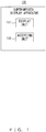
- FIG. 1 illustrates an exemplary functional configuration of a first superimposed display apparatus.
- a superimposed display apparatus 101 in FIG. 1 includes a display unit 111 and an accepting unit 112.
- FIG. 2 is a flowchart illustrating an example of a first superimposed display process performed by the superimposed display apparatus 101 from FIG. 1 .
- the display unit 111 displays edge lines extracted from a shot image of a spatial structure that has been shot by an image shooting apparatus and ridge lines included in a model image represented by model information of that spatial structure, in a manner such that those lines are selectable (step 201).
- the accepting unit 112 accepts a selection instruction indicating an edge line and a ridge line of an overlay target (step 202).
- the display unit 111 displays a superimposition image in which the model image has been superimposed onto the shot image in a manner such that the edge line and the ridge line of the overlay target overlap each other.
- the superimposed display apparatus 101 in FIG. 1 can improve the efficiency of a checking task of comparing a spatial structure and a model represented by model information.
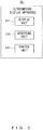
- FIG. 3 illustrates an exemplary functional configuration of a second superimposed display apparatus.
- a superimposed display apparatus 301 in FIG. 3 includes a display unit 311, an accepting unit 312, and a control unit 313.
- FIG. 4 is a flowchart illustrating an example of a second superimposed display process performed by the superimposed display apparatus 301 from FIG. 3 .
- the display unit 311 displays a shot image of a spatial structure that has been shot by an image shooting apparatus, and a model image represented by model information of that spatial structure (step 401).
- the control unit 313 switches between the rule that separate change instructions be accepted for the shot image and the model image, and the rule that a common change instruction be accepted for the shot image and the model image (step 402).
- the superimposed display instruction is an instruction to display a superimposition image in which the model image has been superimposed onto the shot image in a manner such that a reference position on the shot image and a reference position on the model image overlap each other.
- the change instruction is an instruction to enlarge, reduce, move, or rotate the shot image or the model image.
- the superimposed display apparatus 301 in FIG. 3 can improve the efficiency of a checking task of comparing a spatial structure and a model represented by model information.
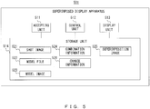
- FIG. 5 illustrates a specific example of the superimposed display apparatus 101 in FIG. 1 or the superimposed display apparatus 301 in FIG. 3 .
- a superimposed display apparatus 501 in FIG. 5 includes an accepting unit 511, a control unit 512, a display unit 513, and a storage unit 514.
- the accepting unit 511 corresponds to the accepting unit 112 in FIG. 1 and the accepting unit 312 in FIG. 3 ; the control unit 512, the control unit 313 in FIG. 3 ; the display unit 513, the display unit 111 in FIG. 1 and the display unit 311 in FIG. 3 .
- the storage unit 514 stores one or more shot images 521, one or more model files 522, a model image 523, combination information 524, a superimposition image 525, and change information 526.
- the shot image 521 is an image of a spatial structure shot by an image shooting apparatus such as a camera, and may include information indicating an angle of view of the image shooting apparatus.
- the model file 522 is model information representing a three-dimensional CAD model of the spatial structure, and includes vertex information of a plurality of vertexes included in the three-dimensional CAD model and line segment information of a plurality of line segments.
- the model image 523 is an image of a three-dimensional CAD model represented by the model file 522.
- Combination information 524 indicates a combination of an edge line and a ridge line of the overlay target that have been selected by an operator.
- the superimposition image 525 is an image in which the model image 523 has been superimposed onto the shot image 521.
- Change information 526 indicates whether to accept separate change instructions for the shot image 521 and the model image 523, or whether to accept a common change instruction for the shot image 521 and the model image 523, the change instructions being instructions to enlarge, reduce, move, or rotate an image.
- the superimposed display apparatus 501 may be a portable terminal apparatus such as a tablet, a notebook PC, or a smartphone, or may be a fixed terminal apparatus such as a desktop PC.
- FIGS. 6A and 6B are flowcharts illustrating a specific example of a superimposed display process performed by the superimposed display apparatus 501 in FIG. 5 .
- An operator inputs an instruction for designating a shot image 521 and a model file 522, and the accepting unit 511 accepts the input instruction (step 601).
- the display unit 513 displays the shot image 521 designated by the instruction accepted by the accepting unit 511 on a screen (step 602).
- FIG. 7 illustrates an example of a displayed shot image 521.
- a rectangular shot image 701 corresponds to a side surface of a cubic spatial structure.
- FIG. 8 illustrates an exemplary three-dimensional CAD model represented by a model file 522 of the spatial structure seen in the shot image 701 in FIG. 7 .
- Vertex information of the model file 522 includes the identification information and three-dimensional coordinates of a vertex 801 and the like of the cube;
- line segment information of the model file 522 includes identification information of line segments 802 and 803 and the like, and identification information indicating the two vertexes at the both ends of each line segment.
- the control unit 512 performs an edge detecting process to extract edge lines from the shot image 521 (step 603), and displays the extracted edge lines on the screen (step 604).
- the control unit 512 may extract straight edge lines only, or may extract straight and curved edge lines.
- FIG. 9 illustrates exemplary edge lines extracted from the shot image 701 in FIG. 7 .
- Edge lines 901-904 are each extracted from a respective one of the four sides of the rectangle of the shot image 701.
- control unit 512 uses vertex information and line segment information of the model file 522 to generate ridge lines of the three-dimensional CAD model (step 605).
- the control unit 512 may extract only a line segment representing a contour feature of a three-dimensional CAD model from a plurality of line segments included in line segment information, and may use the extracted line segment as a ridge line.
- FIG. 10 illustrates exemplary ridge lines generated from the three-dimensional CAD model in FIG. 8 .
- the line segment 802 in FIG. 8 corresponds to an edge of the cube and represents a contour feature, and accordingly the line segment 802 is extracted as a ridge line 1001.
- the line segment 803 is included on a side surface of the cube and does not represent a contour feature, and accordingly the line segment 803 is not extracted as a ridge line.
- the control unit 512 generates a polygon representing a surface surrounded by the generated ridge lines and stores information on the generated ridge lines and the polygon in the storage unit 514 as a model image 523 (step 606).
- the generated polygon represents a part of the surface of the three-dimensional CAD model.
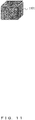
- FIG. 11 illustrates exemplary polygons generated from the ridge lines in FIG. 10 .
- a polygon 1101 represents a rectangular side face surrounded by four ridge lines corresponding to four edges of the cube.
- the control unit 512 displays the model image 523 on the screen together with the shot image 521 (step 607). As a result, the edge lines extracted from the shot image 521 and the ridge lines and polygon included in the model image 523 are displayed so that the edge lines and the ridge lines can be selected on the screen. Simultaneously, the control unit 512 generates change information 526 indicating that separate change instructions are to be accepted for the shot image 521 and the model image 523, and stores the change information 526 in the storage unit 514.
- FIG. 12 illustrates an exemplary model image 523 displayed using the ridge lines in FIG. 10 and the polygons in FIG. 11 .
- the edge lines 901-904 in FIG. 9 and a model image 1201 of the cube are displayed in this example. Displaying ridge lines and, in addition, the polygons as the model image 1201 can cover and hide the ridge lines on the back-surface side of the three-dimensional CAD model using the polygons, so that the outside shape of the three-dimensional CAD model can be readily grasped.
- the operator checks whether the size of the model image 523 on the screen is suitable (step 608).
- the size of the model image 523 is suitable to indicate a correlation between the edge lines of the shot image 521 and the ridge lines of the model image 523, the operator determines that the size of the model image 523 is suitable.
- the operator inputs a change instruction indicating enlargement or reduction of the model image 523, and the accepting unit 511 accepts the input change instruction (step 611). Then, the control unit 512 adjusts the size of the model image 523 by enlarging or reducing the model image 523 in accordance with the change instruction. For example, the control unit 512 may enlarge or reduce the model image 523 by changing the enlargement or reduction ratio of the ridge lines and the polygons.
- FIG. 13 illustrates an example of size adjustment of the model image 1201 depicted in FIG. 12 .
- the model image 1201 has been enlarged in this example.
- the operator checks whether the orientation of the model image 523 on the screen is suitable (step 609).
- the orientation of the model image 523 is suitable to indicate a correlation between the edge lines of the shot image 521 and the ridge lines of the model image 523, the operator determines that the orientation of the model image 523 is suitable.
- the operator inputs a change instruction indicating rotation of the model image 523, and the accepting unit 511 accepts the input change instruction (step 612). Then, the control unit 512 adjusts the orientation of the model image 523 by rotating the model image 523 in accordance with the change instruction. For example, the control unit 512 may rotate the model image 523 by changing the rotation angle of the ridge lines and the polygons.
- FIG. 14 illustrates an example of orientation adjustment of the model image 1201 depicted in FIG. 13 .
- the model image 1201 rotates counterclockwise in this example.
- the operator checks whether the position of the model image 523 on the screen is suitable (step 610).
- the position of the model image 523 is suitable to indicate a correlation between the edge lines of the shot image 521 and the ridge lines of the model image 523, the operator determines that the position of the model image 523 is suitable.
- the operator inputs a change instruction indicating movement of the model image 523, and the accepting unit 511 accepts the input change instruction (step 613). Then, the control unit 512 adjusts the position of the model image 523 by moving the model image 523 in accordance with the change instruction. For example, the control unit 512 may move the model image 523 by changing the positions of the ridge lines and the polygons.
- FIG. 15 illustrates an example of position adjustment of the model image 1201 depicted in FIG. 14 .
- the model image 1201 has moved upward in this example.
- the operator inputs a selection instruction indicating an edge line and a ridge line to serve as reference positions for superimposed display, and the accepting unit 511 accepts the input selection instruction (step 614). Then, the control unit 512 highlights the edge line and the ridge line indicated by the selection instruction by changing, for example, the color, width, or type of the edge line and the ridge line. Highlighting the edge line and the ridge line allows the operator to readily check the selection result.
- the control unit 512 may display a line segment linking the edge line and the ridge line. Displaying a line segment linking the edge line and the ridge line further improves the efficiency of a task of checking the selection result that is performed by the operator.
- FIG. 16 illustrates an exemplary edge line and ridge line selected on the screen depicted in FIG. 15 .
- an edge line 901 and a ridge line 1601 have been selected, and a line segment 1611 linking the edge line 901 and the ridge line 1601 is displayed.
- the operator checks whether a combination of a highlighted edge line and ridge line is suitable (step 615). When, for example, the highlighted edge line and ridge line correspond to the same ridge line of the spatial structure, the operator determines that the combination is suitable.
- the operator gives an instruction to cancel the combination of the selected lines, and the accepting unit 511 accepts the input instruction (step 622). Then, the control unit 512 cancels the highlighting of the edge line and the ridge line. Simultaneously, the control unit 512 hides the line segment linking the edge line and the ridge line.
- FIG. 17 illustrates examples of an edge line and ridge line after cancellation.
- a combination of a selected edge line 903 and ridge line 1701 has been cancelled, and a line segment 1702 linking the edge line 903 and the ridge line 1701 has been hidden.
- N is an integer that is 1 or greater. As N becomes a lower value, a task time of an operator is shortened, but the accuracy of the superimposed display decreases. Meanwhile, as N becomes a higher value, a task time of an operator is lengthened, but the accuracy of the superimposed display increases. N may be any of 1 to 4.
- step 616 When N combinations have not been selected (NO in step 616), the operator repeats the operations of step 614 and the following steps; when N combinations have been selected (YES in step 616), the operator inputs a superimposition instruction (step 617).
- the accepting unit 511 accepts the input superimposition instruction.
- the control unit 512 generates and stores combination information 524 indicating the selected N combinations in the storage unit 514.
- FIG. 18 illustrates four exemplary combinations of an edge line and a ridge line.
- a combination of an edge line 901 and a ridge line 1601, a combination of an edge line 902 and a ridge line 1602, a combination of an edge line 903 and a ridge line 1603, and a combination of an edge line 904 and a ridge line 1604 have been selected.
- a line segment 1611 linking the edge line 901 and the ridge line 1601, a line segment 1612 linking the edge line 902 and the ridge line 1602, a line segment 1613 linking the edge line 903 and the ridge line 1603, and a line segment 1614 linking the edge line 904 and the ridge line 1604 have been displayed.
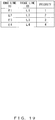
- FIG. 19 illustrates an example of combination information 524.
- Each entry of combination information 524 of FIG. 19 includes an edge line ID, a ridge line ID, and a priority.
- An edge ID is identification information of an edge line included in a combination
- a ridge line ID is identification information of a ridge line included in the combination
- a priority indicates the degree of priority of the combination that is determined according to a prescribed standard.
- an order in which a combination of an edge line and a ridge line is selected by the operator may be directly used as a priority, or a higher priority may be given to combinations with more reliable ridge lines.
- a higher priority may be given to combinations with more reliable ridge lines.
- the reliability levels of ridge lines with a high processing accuracy or assembling accuracy may become high, and the reliability levels of ridge lines with a low processing accuracy or assembling accuracy may become low.
- information indicating the reliability of each line segment is added to line segment information of the model file 522, and the control unit 512 determines priorities for combinations by referring to the reliabilities of selected ridge lines.
- E1 to E4 represent the edge line IDs of the edge lines 901 to 904 in FIG. 18 ; L1 to L4, the ridge line IDs of the ridge lines 1601 to 1604.
- a combination of E1 and L1 has the highest priority, and a combination of E4 and L4 has the lowest priority.
- the control unit 512 generates a superimposition image 525 in which a model image 523 has been superimposed onto a shot image 521 in a manner such that an edge line and a ridge line included in each combination in combination information 524 overlap each other, and stores the superimposition image 525 in the storage unit 514 (step 618).
- the control unit 512 may superimpose the model image 523 onto the shot image 521 by adjusting the enlargement or reduction ratio, rotation angle, and position of ridge lines and polygons of the model image 523.
- control unit 512 calculates optimum values for the enlargement or reduction ratio, rotation angle, and position of the ridge lines and polygons, thereby generating a superimposition image 525 with the edge lines and the ridged lines moderately coinciding with each other.
- the control unit 512 cancels highlighting of the edge lines and the ridge lines and hides the edge lines (step 619). Simultaneously, the control unit 512 also hides line segments linking the edge lines and the ridge lines.
- the control unit 512 displays the superimposition image 525 on the screen (step 620).
- the control unit 512 may change, for example, the color, width, and type of an edge line and a ridge line included in each combination in combination information 524, thereby highlighting the edge line and the ridge line. Highlighting the edge line and the ridge line allows the operator to readily check the edge line and the ridge line that have been overlaid in superimposed display.
- the control unit 512 switches the change information 526 in the storage unit 514 to information indicating that a common change instruction is to be accepted for the shot image 521 and the model image 523.
- FIG. 20 illustrates an exemplary superimposition image 525 in which the model image 1201 in FIG. 12 has been superimposed onto the shot image 701 in FIG. 7 .
- the operator looks at the superimposition image 525 on the screen so as to check misalignments between the shot image 521 and the model image 523.
- the operator inputs a change instruction for the superimposition image 525, and, in accordance with change information 526, the accepting unit 511 accepts the input change instruction as a common instruction for the shot image 521 and the model image 523 (step 621).
- the control unit 512 adjusts the size, orientation, or position of the superimposition image 525 by enlarging, reducing, rotating, or moving the entirety of the superimposition image 525 in accordance with the change instruction.
- FIG. 21 illustrates an exemplary superimposed display process on another shot image 521.
- an edge line 2102 is extracted from a shot image 2101 of a spatial structure in an edge detecting process, and a model image 2103 generated from a three-dimensional CAD model of the spatial structure is displayed together with the shot image 2101 and the edge line 2102.
- a combination of an edge line 2111 of the shot image 2101 and a ridge line 2121 of the model image 2103 is highlighted in accordance with a selection instruction input by an operator.
- a combination of an edge line 2112 and a ridge line 2122, a combination of an edge line 2113 and a ridge line 2123, and a combination of an edge line 2114 and a ridge line 2124 are highlighted.
- a line segment 2131 linking the edge line 2111 and the ridge line 2121, a line segment 2132 linking the edge line 2112 and the ridge line 2122, a line segment 2133 linking the edge line 2113 and the ridge line 2123, and a line segment 2134 linking the edge line 2114 and the ridge line 2124 are displayed.
- a superimposition image 2104 is displayed in which the model image 2103 has been superimposed onto the shot image 2101 in a manner such that the edge lines 2111-2114 respectively overlap the ridge lines 2121-2124.
- FIG. 22 is a flowchart illustrating an exemplary adjusting process performed after the superimposed display process in FIG. 6B is performed.
- the size, orientation, or position of a shot image 521 or model image 523 included in a superimposition image 525 is adjusted according to priorities included in combination information 524.
- An operator looks at the superimposition image 525 on the screen so as to check whether the shot image 521 and the model image 523 are misaligned (step 2201). When the shot image 521 and the model image 523 are aligned (NO in step 2201), the operator ends the checking task.
- control unit 512 sets 1 as control variable i, which indicates priority (step 2202).
- the control unit 512 selects an entry with priority i in combination information 524, obtains an edge line ID and a ridge line ID from the selected entry, and highlights an edge line and ridge line indicated by the obtained edge line ID and ridge line ID (step 2203). The operator determines whether to make an adjustment using a combination of the highlighted edge line and ridge line as a reference.
- the operator In making an adjustment using the combination of the highlighted edge line and ridge line as a reference (YES in step 2203), the operator inputs an execution instruction, and the accepting unit 511 accepts the input execution instruction.
- the control unit 512 adjusts the superimposition image 525 by enlarging, reducing, rotating, or moving the model image 523 in a manner such that the highlighted edge line and ridge line coincide with each other (step 2204).
- the control unit 512 checks whether i has reached N (step 2205). When i has not reached N (NO in step 2205), the control unit 512 increments i by one (step 2206), and repeats the processes of step 2203 and the following steps. When i has reached N (YES in step 2205), the control unit 512 ends the process.
- FIG. 23 illustrates an exemplary adjusting process on the superimposition image 2104 in FIG. 21 .
- the priorities of combinations of an edge line and a ridge line are as follows.
- a superimposition image 2104 After a superimposition image 2104 has been displayed in which a model image 2103 has been superimposed onto a shot image 2101, when an operator designates a combination with priority 1 or 2 as a reference, the superimposition image 2104 is replaced with a superimposition image 2301 on the screen.
- the superimposition image 2301 In which the edge line 2111 and the ridge line 2121 coincide with each other, is displayed; when a combination with priority 2 is designated, the superimposition image 2301, in which the edge line 2112 and the ridge line 2122 coincide with each other, is displayed.
- the superimposition image 2301 is replaced with a superimposition image 2302 on the screen.
- the superimposition image 2302 in which the edge line 2113 and the ridge line 2123 coincide with each other, is displayed.
- the superimposition image 2302 is replaced with a superimposition image 2303 on the screen.
- the superimposition image 2303 in which the edge line 2114 and the ridge line 2124 coincide with each other, is displayed.
- the configurations of the superimposed display apparatus 101 in FIG. 1 , the superimposed display apparatus 301 in FIG. 3 , and the superimposed display apparatus 501 in FIG. 5 are merely examples, and some components may be omitted or changed according to the intended use or conditions of the superimposed display apparatuses.
- change information 526 in FIG. 5 may be omitted; when the operator does not input a selection instruction indicating an edge line and a ridge line of an overlay target, combination information 524 may be omitted.
- FIGS. 2 , 4 , 6A , 6B , and 22 are merely examples, and some processes may be omitted or changed according to the configuration or conditions of the superimposed display apparatus. For example, when polygons of the model image 523 do not need to be displayed in the superimposed display processes in FIGS. 6A and 6B , the process of step 606 may be omitted. When the size, orientation, and position of the model image 523 do not need to be adjusted, the processes of steps 608-613 may be omitted.
- steps 615 and 622 may be omitted.
- the process of step 621 may be omitted.
- the processes of steps 608-617 may be omitted.
- a set of steps 602-604 and a set of steps 605-607 may be performed in reverse order.
- the control unit 512 does not always need to highlight a selected edge line and ridge line.
- the shot images, model information, edge lines, ridge lines, polygons, model images, superimposition images, and combination information in FIGS. 7-21 and 23 are merely examples, and other images or other pieces of information may be used.
- the superimposed display apparatus 101 in FIG. 1 , the superimposed display apparatus 301 in FIG. 3 , and the superimposed display apparatus 501 in FIG. 5 can be implemented using, for example, an information processing apparatus (computer) such as that depicted in FIG. 24 .
- the information processing apparatus in FIG. 24 includes a Central Processing Unit (CPU) 2401, a memory 2402, an input device 2403, an output device 2404, an auxiliary storage device 2405, a medium driving device 2406, and a network connecting device 2407. These elements are connected to each other by a bus 2408.
- CPU Central Processing Unit
- the memory 2402 is, for example, a semiconductor memory such as a Read Only Memory (ROM), a Random Access Memory (RAM), or a flash memory, and stores programs and data for use in processing.
- the memory 2402 may be used as the storage unit 514 in FIG. 5 .
- the CPU 2401 (processor) operates as the control unit 313 in FIG. 3 and the control unit 512 in FIG. 5 by, for example, executing a program using the memory 2402.
- the input device 2403 is, for example, a keyboard or a pointing device and is used to input an instruction or information from an operator.
- the input device 2403 may be used as the accepting unit 112 in FIG. 1 , the accepting unit 312 in FIG. 3 , and the accepting unit 511 in FIG. 5 .
- the output device 2404 is, for example, a display device, a printer, or a speaker, and is used to output a query or a processing result to the operator.
- the processing result may be a superimposition image 525.
- the output device 2404 may be used as the display unit 111 in FIG. 1 , the display unit 311 in FIG. 3 , and the display unit 513 in FIG. 5 .
- the auxiliary storage device 2405 is, for example, a magnetic disk device, an optical disk device, a magneto-optical disk device, or a tape device.
- the auxiliary storage device 2405 may be a hard disk drive or a flash memory.
- the information processing apparatus may store a program and data in the auxiliary storage device 2405 and load them into the memory 2402 for use.
- the auxiliary storage device 2405 may be used as the storage unit 514 in FIG. 5 .
- the medium driving device 2406 drives a portable recording medium 2409 and accesses items recorded therein.
- the portable recording medium 2409 is, for example, a memory device, a flexible disk, an optical disk, or a magneto-optical disk.
- the portable recording medium 2409 may be, for example, a Compact Disk Read Only Memory (CD-ROM), a Digital Versatile Disk (DVD), or a Universal Serial Bus (USB) memory.
- CD-ROM Compact Disk Read Only Memory
- DVD Digital Versatile Disk
- USB Universal Serial Bus
- a computer-readable recording medium that stores a program and data to be used for processing is a physical (non-transitory) recording medium such as the memory 2402, the auxiliary storage apparatus 2405, or the portable recording medium 2409.
- the network connecting device 2407 is a communication interface that is connected to a communication network such as a Local Area Network or a Wide Area Network and that performs data conversion associated with a communication.
- the information processing apparatus may receive a program and data from an external apparatus via the network connecting device 2407 and load them into the memory 2402 for use.
- the information processing apparatus does not need to include all of the elements in FIG. 24 , and one or more of the elements may be omitted according to the intended use or conditions.
- the network connecting device 2407 may be omitted when a communication does not need to be performed with another apparatus; the medium driving device 2406 may be omitted when the portable recording medium 2409 is not used.
- the information processing apparatus may include a call apparatus such as a microphone or a speaker, or may include an image shooting apparatus such as a camera.
Landscapes
- Engineering & Computer Science (AREA)
- Physics & Mathematics (AREA)
- General Physics & Mathematics (AREA)
- Theoretical Computer Science (AREA)
- Software Systems (AREA)
- Computer Graphics (AREA)
- General Engineering & Computer Science (AREA)
- Computer Hardware Design (AREA)
- Architecture (AREA)
- Quality & Reliability (AREA)
- Computer Vision & Pattern Recognition (AREA)
- Geometry (AREA)
- Remote Sensing (AREA)
- Radar, Positioning & Navigation (AREA)
- Processing Or Creating Images (AREA)
- Image Processing (AREA)
- Controls And Circuits For Display Device (AREA)
- Image Analysis (AREA)
Abstract
Description
- The embodiments discussed herein are related to a superimposed display method and a superimposed display apparatus.
- In constructing spatial structures such as steel towers and bridges in the iron & steel industry, a component processing process, a welding process, and a tentative assembly process may be performed in steps from Computer-Aided-Design-based (CAD-based) designing to on-site assembling. Following the tentative assembly process, components are shipped to a construction site so as to perform on-site assembling. In the component processing process, steel components of a spatial structure are processed; in the welding process, steel components are tentatively welded, the tentative welding is diagnosed, and regular welding is performed; in the tentative assembly process, tentative assembling, disassembling, paint finishing, and diagnoses are performed.
- Such a spatial structure is often one large item. Accordingly, diagnoses in the welding process and the tentative assembly process are frequently performed through visual checking of comparing a tentatively welded or painted object with a three-dimensional CAD model created in a designing process.
- When a fault in the welding process is overlooked in a diagnosis and is found during a tentative assembly task, a returning operation from the tentative assembly process to the component processing process occurs. When a fault in the tentative assembly process is overlooked in a diagnosis and is found during an on-site assembling task, a returning operation from the on-site assembling to the component processing process occurs.
- A technique for superimposing and displaying an image of an object and an image of a three-dimensional model is also known in the field of image processing (see, for example, patent documents 1-3).
- Patent Document 1: Japanese Laid-open Patent Publication No.
2010-211746 - Patent Document 2: Japanese Laid-open Patent Publication No.
11-239989 - Patent Document 3: International Publication Pamphlet No.
WO 2012/173141 - It is an object in one aspect of the invention to improve the efficiency of a checking task of comparing a spatial structure and a model represented by model information.
- According to an aspect of the embodiments, a computer executes the following process.
- (1) The computer displays a plurality of edge lines extracted from a shot image of a spatial structure that has been shot by an image shooting apparatus and a plurality of ridge lines included in a model image represented by model information of that spatial structure, in a manner such that the edge lines and the ridge lines are selectable.
- (2) The computer accepts a selection instruction indicating an edge line and a ridge line of an overlay target.
- (3) In accordance with the accepted selection instruction, the computer displays a superimposition image in which the model image has been superimposed onto the shot image in a manner such that the edge line and the ridge line of the overlay target overlap each other.
-
-
FIG. 1 is a functional configuration diagram of a first superimposed display apparatus. -
FIG. 2 is a flowchart of a first superimposed display process. -
FIG. 3 is a functional configuration diagram of a second superimposed display apparatus. -
FIG. 4 is a flowchart of a second superimposed display process. -
FIG. 5 is a functional configuration diagram illustrating a specific example of a superimposed display apparatus. -
FIG. 6A is a flowchart illustrating a specific example of a superimposed display process (part 1). -
FIG. 6B is a flowchart illustrating a specific example of a superimposed display process (part 2). -
FIG. 7 illustrates a shot image. -
FIG. 8 illustrates model information. -
FIG. 9 illustrates edge lines. -
FIG. 10 illustrates ridge lines. -
FIG. 11 illustrates polygons. -
FIG. 12 illustrates a model image. -
FIG. 13 illustrates adjustment of the size of a model image. -
FIG. 14 illustrates adjustment of the orientation of a model image. -
FIG. 15 illustrates adjustment of the position of a model image. -
FIG. 16 illustrates selected edge lines and ridge lines. -
FIG. 17 illustrates an edge line and a ridge line after cancellation. -
FIG. 18 illustrates four combinations of edge and ridge lines. -
FIG. 19 illustrates combination information. -
FIG. 20 illustrates a superimposition image. -
FIG. 21 illustrates a superimposed display process. -
FIG. 22 is a flowchart of an adjusting process. -
FIG. 23 illustrates an adjusting process. -
FIG. 24 is a configuration diagram of an information processing apparatus. - The following describes embodiments in detail with reference to the drawings.
- Digitization of diagnostic methods has not been developed for the conventional task of constructing spatial structures. Accordingly, to prevent a returning operation from occurring in tentative assembling and on-site assembling, a certain task time is spend on visual checking of comparing an object and a three-dimensional CAD model. An increase in the number of components leads to more portions of a spatial structure to be diagnosed, thereby extending the task time for visual checking. In addition, it is not easy to develop a skilled operator who can conduct accurate analyses in a short time, and several years may be required to develop such a skilled operator.
- Such problems are not limited to diagnoses in tasks of constructing steel towers, bridges, or the like, and arise in a checking task of comparing another spatial structure and a model represented by model information of that structure.
-
FIG. 1 illustrates an exemplary functional configuration of a first superimposed display apparatus. Asuperimposed display apparatus 101 inFIG. 1 includes adisplay unit 111 and an acceptingunit 112. -
FIG. 2 is a flowchart illustrating an example of a first superimposed display process performed by thesuperimposed display apparatus 101 fromFIG. 1 . Thedisplay unit 111 displays edge lines extracted from a shot image of a spatial structure that has been shot by an image shooting apparatus and ridge lines included in a model image represented by model information of that spatial structure, in a manner such that those lines are selectable (step 201). - The accepting
unit 112 accepts a selection instruction indicating an edge line and a ridge line of an overlay target (step 202). In accordance with the selection instruction accepted by the acceptingunit 112, thedisplay unit 111 displays a superimposition image in which the model image has been superimposed onto the shot image in a manner such that the edge line and the ridge line of the overlay target overlap each other. - The
superimposed display apparatus 101 inFIG. 1 can improve the efficiency of a checking task of comparing a spatial structure and a model represented by model information. -
FIG. 3 illustrates an exemplary functional configuration of a second superimposed display apparatus. Asuperimposed display apparatus 301 inFIG. 3 includes adisplay unit 311, an acceptingunit 312, and acontrol unit 313. -
FIG. 4 is a flowchart illustrating an example of a second superimposed display process performed by the superimposeddisplay apparatus 301 fromFIG. 3 . Thedisplay unit 311 displays a shot image of a spatial structure that has been shot by an image shooting apparatus, and a model image represented by model information of that spatial structure (step 401). - Before and after the accepting
unit 312 accepts a superimposed display instruction, thecontrol unit 313 switches between the rule that separate change instructions be accepted for the shot image and the model image, and the rule that a common change instruction be accepted for the shot image and the model image (step 402). The superimposed display instruction is an instruction to display a superimposition image in which the model image has been superimposed onto the shot image in a manner such that a reference position on the shot image and a reference position on the model image overlap each other. The change instruction is an instruction to enlarge, reduce, move, or rotate the shot image or the model image. - The superimposed
display apparatus 301 inFIG. 3 can improve the efficiency of a checking task of comparing a spatial structure and a model represented by model information. -
FIG. 5 illustrates a specific example of the superimposeddisplay apparatus 101 inFIG. 1 or the superimposeddisplay apparatus 301 inFIG. 3 . A superimposeddisplay apparatus 501 inFIG. 5 includes an acceptingunit 511, acontrol unit 512, adisplay unit 513, and astorage unit 514. The acceptingunit 511 corresponds to the acceptingunit 112 inFIG. 1 and the acceptingunit 312 inFIG. 3 ; thecontrol unit 512, thecontrol unit 313 inFIG. 3 ; thedisplay unit 513, thedisplay unit 111 inFIG. 1 and thedisplay unit 311 inFIG. 3 . - The
storage unit 514 stores one ormore shot images 521, one or more model files 522, amodel image 523,combination information 524, asuperimposition image 525, and changeinformation 526. Theshot image 521 is an image of a spatial structure shot by an image shooting apparatus such as a camera, and may include information indicating an angle of view of the image shooting apparatus. Themodel file 522 is model information representing a three-dimensional CAD model of the spatial structure, and includes vertex information of a plurality of vertexes included in the three-dimensional CAD model and line segment information of a plurality of line segments. - The
model image 523 is an image of a three-dimensional CAD model represented by themodel file 522.Combination information 524 indicates a combination of an edge line and a ridge line of the overlay target that have been selected by an operator. Thesuperimposition image 525 is an image in which themodel image 523 has been superimposed onto theshot image 521.Change information 526 indicates whether to accept separate change instructions for theshot image 521 and themodel image 523, or whether to accept a common change instruction for theshot image 521 and themodel image 523, the change instructions being instructions to enlarge, reduce, move, or rotate an image. - The superimposed
display apparatus 501 may be a portable terminal apparatus such as a tablet, a notebook PC, or a smartphone, or may be a fixed terminal apparatus such as a desktop PC. -
FIGS. 6A and6B are flowcharts illustrating a specific example of a superimposed display process performed by the superimposeddisplay apparatus 501 inFIG. 5 . An operator inputs an instruction for designating ashot image 521 and amodel file 522, and the acceptingunit 511 accepts the input instruction (step 601). Thedisplay unit 513 displays theshot image 521 designated by the instruction accepted by the acceptingunit 511 on a screen (step 602). -
FIG. 7 illustrates an example of a displayedshot image 521. Arectangular shot image 701 corresponds to a side surface of a cubic spatial structure. -
FIG. 8 illustrates an exemplary three-dimensional CAD model represented by amodel file 522 of the spatial structure seen in theshot image 701 inFIG. 7 . Vertex information of themodel file 522 includes the identification information and three-dimensional coordinates of avertex 801 and the like of the cube; line segment information of themodel file 522 includes identification information ofline segments - The
control unit 512 performs an edge detecting process to extract edge lines from the shot image 521 (step 603), and displays the extracted edge lines on the screen (step 604). In this case, thecontrol unit 512 may extract straight edge lines only, or may extract straight and curved edge lines. -
FIG. 9 illustrates exemplary edge lines extracted from theshot image 701 inFIG. 7 . Edge lines 901-904 are each extracted from a respective one of the four sides of the rectangle of theshot image 701. - Using vertex information and line segment information of the
model file 522, thecontrol unit 512 generates ridge lines of the three-dimensional CAD model (step 605). For example, thecontrol unit 512 may extract only a line segment representing a contour feature of a three-dimensional CAD model from a plurality of line segments included in line segment information, and may use the extracted line segment as a ridge line. -
FIG. 10 illustrates exemplary ridge lines generated from the three-dimensional CAD model inFIG. 8 . Theline segment 802 inFIG. 8 corresponds to an edge of the cube and represents a contour feature, and accordingly theline segment 802 is extracted as aridge line 1001. Meanwhile, theline segment 803 is included on a side surface of the cube and does not represent a contour feature, and accordingly theline segment 803 is not extracted as a ridge line. - The
control unit 512 generates a polygon representing a surface surrounded by the generated ridge lines and stores information on the generated ridge lines and the polygon in thestorage unit 514 as a model image 523 (step 606). The generated polygon represents a part of the surface of the three-dimensional CAD model. -
FIG. 11 illustrates exemplary polygons generated from the ridge lines inFIG. 10 . Apolygon 1101 represents a rectangular side face surrounded by four ridge lines corresponding to four edges of the cube. - The
control unit 512 displays themodel image 523 on the screen together with the shot image 521 (step 607). As a result, the edge lines extracted from theshot image 521 and the ridge lines and polygon included in themodel image 523 are displayed so that the edge lines and the ridge lines can be selected on the screen. Simultaneously, thecontrol unit 512 generateschange information 526 indicating that separate change instructions are to be accepted for theshot image 521 and themodel image 523, and stores thechange information 526 in thestorage unit 514. -
FIG. 12 illustrates anexemplary model image 523 displayed using the ridge lines inFIG. 10 and the polygons inFIG. 11 . The edge lines 901-904 inFIG. 9 and amodel image 1201 of the cube are displayed in this example. Displaying ridge lines and, in addition, the polygons as themodel image 1201 can cover and hide the ridge lines on the back-surface side of the three-dimensional CAD model using the polygons, so that the outside shape of the three-dimensional CAD model can be readily grasped. - The operator checks whether the size of the
model image 523 on the screen is suitable (step 608). When, for example, the size of themodel image 523 is suitable to indicate a correlation between the edge lines of theshot image 521 and the ridge lines of themodel image 523, the operator determines that the size of themodel image 523 is suitable. - When the size of the
model image 523 is unsuitable (NO in step 608), the operator inputs a change instruction indicating enlargement or reduction of themodel image 523, and the acceptingunit 511 accepts the input change instruction (step 611). Then, thecontrol unit 512 adjusts the size of themodel image 523 by enlarging or reducing themodel image 523 in accordance with the change instruction. For example, thecontrol unit 512 may enlarge or reduce themodel image 523 by changing the enlargement or reduction ratio of the ridge lines and the polygons. -
FIG. 13 illustrates an example of size adjustment of themodel image 1201 depicted inFIG. 12 . Themodel image 1201 has been enlarged in this example. - When the size of the
model image 523 is suitable (YES in step 608), the operator checks whether the orientation of themodel image 523 on the screen is suitable (step 609). When, for example, the orientation of themodel image 523 is suitable to indicate a correlation between the edge lines of theshot image 521 and the ridge lines of themodel image 523, the operator determines that the orientation of themodel image 523 is suitable. - When the orientation of the
model image 523 is unsuitable (NO in step 609), the operator inputs a change instruction indicating rotation of themodel image 523, and the acceptingunit 511 accepts the input change instruction (step 612). Then, thecontrol unit 512 adjusts the orientation of themodel image 523 by rotating themodel image 523 in accordance with the change instruction. For example, thecontrol unit 512 may rotate themodel image 523 by changing the rotation angle of the ridge lines and the polygons. -
FIG. 14 illustrates an example of orientation adjustment of themodel image 1201 depicted inFIG. 13 . Themodel image 1201 rotates counterclockwise in this example. - When the orientation of the
model image 523 is suitable (YES in step 609), the operator checks whether the position of themodel image 523 on the screen is suitable (step 610). When, for example, the position of themodel image 523 is suitable to indicate a correlation between the edge lines of theshot image 521 and the ridge lines of themodel image 523, the operator determines that the position of themodel image 523 is suitable. - When the orientation of the
model image 523 is unsuitable (NO in step 610), the operator inputs a change instruction indicating movement of themodel image 523, and the acceptingunit 511 accepts the input change instruction (step 613). Then, thecontrol unit 512 adjusts the position of themodel image 523 by moving themodel image 523 in accordance with the change instruction. For example, thecontrol unit 512 may move themodel image 523 by changing the positions of the ridge lines and the polygons. -
FIG. 15 illustrates an example of position adjustment of themodel image 1201 depicted inFIG. 14 . Themodel image 1201 has moved upward in this example. - When the position of the
model image 523 is suitable (YES in step 610), the operator inputs a selection instruction indicating an edge line and a ridge line to serve as reference positions for superimposed display, and the acceptingunit 511 accepts the input selection instruction (step 614). Then, thecontrol unit 512 highlights the edge line and the ridge line indicated by the selection instruction by changing, for example, the color, width, or type of the edge line and the ridge line. Highlighting the edge line and the ridge line allows the operator to readily check the selection result. - The
control unit 512 may display a line segment linking the edge line and the ridge line. Displaying a line segment linking the edge line and the ridge line further improves the efficiency of a task of checking the selection result that is performed by the operator. -
FIG. 16 illustrates an exemplary edge line and ridge line selected on the screen depicted inFIG. 15 . In this example, anedge line 901 and aridge line 1601 have been selected, and aline segment 1611 linking theedge line 901 and theridge line 1601 is displayed. - The operator checks whether a combination of a highlighted edge line and ridge line is suitable (step 615). When, for example, the highlighted edge line and ridge line correspond to the same ridge line of the spatial structure, the operator determines that the combination is suitable.
- When the combination is unsuitable (NO in step 615), the operator gives an instruction to cancel the combination of the selected lines, and the accepting
unit 511 accepts the input instruction (step 622). Then, thecontrol unit 512 cancels the highlighting of the edge line and the ridge line. Simultaneously, thecontrol unit 512 hides the line segment linking the edge line and the ridge line. -
FIG. 17 illustrates examples of an edge line and ridge line after cancellation. In this example, a combination of a selectededge line 903 andridge line 1701 has been cancelled, and aline segment 1702 linking theedge line 903 and theridge line 1701 has been hidden. - The operator repeats the operations of
step 614 and the following steps, and, when a combination is suitable (YES in step 615), the operator checks whether N combinations of lines of the overlay target have been selected (step 616). N is an integer that is 1 or greater. As N becomes a lower value, a task time of an operator is shortened, but the accuracy of the superimposed display decreases. Meanwhile, as N becomes a higher value, a task time of an operator is lengthened, but the accuracy of the superimposed display increases. N may be any of 1 to 4. - When N combinations have not been selected (NO in step 616), the operator repeats the operations of
step 614 and the following steps; when N combinations have been selected (YES in step 616), the operator inputs a superimposition instruction (step 617). The acceptingunit 511 accepts the input superimposition instruction. Thecontrol unit 512 generates andstores combination information 524 indicating the selected N combinations in thestorage unit 514. -
FIG. 18 illustrates four exemplary combinations of an edge line and a ridge line. In this example, a combination of anedge line 901 and aridge line 1601, a combination of anedge line 902 and aridge line 1602, a combination of anedge line 903 and aridge line 1603, and a combination of anedge line 904 and aridge line 1604 have been selected. In addition, aline segment 1611 linking theedge line 901 and theridge line 1601, aline segment 1612 linking theedge line 902 and theridge line 1602, aline segment 1613 linking theedge line 903 and theridge line 1603, and aline segment 1614 linking theedge line 904 and theridge line 1604 have been displayed. -
FIG. 19 illustrates an example ofcombination information 524. Each entry ofcombination information 524 ofFIG. 19 includes an edge line ID, a ridge line ID, and a priority. An edge ID is identification information of an edge line included in a combination, a ridge line ID is identification information of a ridge line included in the combination, and a priority indicates the degree of priority of the combination that is determined according to a prescribed standard. - For example, an order in which a combination of an edge line and a ridge line is selected by the operator may be directly used as a priority, or a higher priority may be given to combinations with more reliable ridge lines. For example, among the ridge lines of components of a spatial structure, the reliability levels of ridge lines with a high processing accuracy or assembling accuracy may become high, and the reliability levels of ridge lines with a low processing accuracy or assembling accuracy may become low. In this case, information indicating the reliability of each line segment is added to line segment information of the
model file 522, and thecontrol unit 512 determines priorities for combinations by referring to the reliabilities of selected ridge lines. - E1 to E4 represent the edge line IDs of the
edge lines 901 to 904 inFIG. 18 ; L1 to L4, the ridge line IDs of theridge lines 1601 to 1604. A combination of E1 and L1 has the highest priority, and a combination of E4 and L4 has the lowest priority. - The
control unit 512 generates asuperimposition image 525 in which amodel image 523 has been superimposed onto ashot image 521 in a manner such that an edge line and a ridge line included in each combination incombination information 524 overlap each other, and stores thesuperimposition image 525 in the storage unit 514 (step 618). For example, thecontrol unit 512 may superimpose themodel image 523 onto theshot image 521 by adjusting the enlargement or reduction ratio, rotation angle, and position of ridge lines and polygons of themodel image 523. - When N is 2 or greater, it is rare for all of the plurality combinations to include an edge line and a ridge line that coincide with each other. In this case, the
control unit 512 calculates optimum values for the enlargement or reduction ratio, rotation angle, and position of the ridge lines and polygons, thereby generating asuperimposition image 525 with the edge lines and the ridged lines moderately coinciding with each other. - The
control unit 512 cancels highlighting of the edge lines and the ridge lines and hides the edge lines (step 619). Simultaneously, thecontrol unit 512 also hides line segments linking the edge lines and the ridge lines. - The
control unit 512 displays thesuperimposition image 525 on the screen (step 620). Thecontrol unit 512 may change, for example, the color, width, and type of an edge line and a ridge line included in each combination incombination information 524, thereby highlighting the edge line and the ridge line. Highlighting the edge line and the ridge line allows the operator to readily check the edge line and the ridge line that have been overlaid in superimposed display. Thecontrol unit 512 switches thechange information 526 in thestorage unit 514 to information indicating that a common change instruction is to be accepted for theshot image 521 and themodel image 523. -
FIG. 20 illustrates anexemplary superimposition image 525 in which themodel image 1201 inFIG. 12 has been superimposed onto theshot image 701 inFIG. 7 . - The operator looks at the
superimposition image 525 on the screen so as to check misalignments between theshot image 521 and themodel image 523. To check a misalignment the operator wishes to check, the operator inputs a change instruction for thesuperimposition image 525, and, in accordance withchange information 526, the acceptingunit 511 accepts the input change instruction as a common instruction for theshot image 521 and the model image 523 (step 621). Thecontrol unit 512 adjusts the size, orientation, or position of thesuperimposition image 525 by enlarging, reducing, rotating, or moving the entirety of thesuperimposition image 525 in accordance with the change instruction. - In such a superimposed display process, simply selecting an edge line and a ridge line respectively from a
shot image 521 and amodel image 523 displayed on one screen automatically displays asuperimposition image 525 in which the selected edge line and ridge line overlap each other. Accordingly, a misalignment between theshot image 521 of a spatial structure and themodel image 523 of a three-dimensional CAD model of that structure can be instantly checked, thereby improving the efficiency of a checking task of comparing the spatial structure and the three-dimensional CAD model. Moreover, even unskilled operators can conduct a precise diagnosis in a short time. -
FIG. 21 illustrates an exemplary superimposed display process on anothershot image 521. First, anedge line 2102 is extracted from ashot image 2101 of a spatial structure in an edge detecting process, and amodel image 2103 generated from a three-dimensional CAD model of the spatial structure is displayed together with theshot image 2101 and theedge line 2102. - Next, a combination of an
edge line 2111 of theshot image 2101 and aridge line 2121 of themodel image 2103 is highlighted in accordance with a selection instruction input by an operator. In addition, a combination of anedge line 2112 and aridge line 2122, a combination of anedge line 2113 and aridge line 2123, and a combination of anedge line 2114 and aridge line 2124 are highlighted. Aline segment 2131 linking theedge line 2111 and theridge line 2121, aline segment 2132 linking theedge line 2112 and theridge line 2122, aline segment 2133 linking theedge line 2113 and theridge line 2123, and aline segment 2134 linking theedge line 2114 and theridge line 2124 are displayed. - After those four combinations are selected, a
superimposition image 2104 is displayed in which themodel image 2103 has been superimposed onto theshot image 2101 in a manner such that the edge lines 2111-2114 respectively overlap the ridge lines 2121-2124. -
FIG. 22 is a flowchart illustrating an exemplary adjusting process performed after the superimposed display process inFIG. 6B is performed. In the adjusting process, the size, orientation, or position of ashot image 521 ormodel image 523 included in asuperimposition image 525 is adjusted according to priorities included incombination information 524. - An operator looks at the
superimposition image 525 on the screen so as to check whether theshot image 521 and themodel image 523 are misaligned (step 2201). When theshot image 521 and themodel image 523 are aligned (NO in step 2201), the operator ends the checking task. - When the
shot image 521 and themodel image 523 are misaligned (YES in step 2201), the operator inputs an adjustment instruction for thesuperimposition image 525, and the acceptingunit 511 accepts the input adjustment instruction. In accordance with the adjustment instruction, thecontrol unit 512sets 1 as control variable i, which indicates priority (step 2202). - The
control unit 512 selects an entry with priority i incombination information 524, obtains an edge line ID and a ridge line ID from the selected entry, and highlights an edge line and ridge line indicated by the obtained edge line ID and ridge line ID (step 2203). The operator determines whether to make an adjustment using a combination of the highlighted edge line and ridge line as a reference. - In making an adjustment using the combination of the highlighted edge line and ridge line as a reference (YES in step 2203), the operator inputs an execution instruction, and the accepting
unit 511 accepts the input execution instruction. In accordance with the execution instruction, thecontrol unit 512 adjusts thesuperimposition image 525 by enlarging, reducing, rotating, or moving themodel image 523 in a manner such that the highlighted edge line and ridge line coincide with each other (step 2204). - The
control unit 512 checks whether i has reached N (step 2205). When i has not reached N (NO in step 2205), thecontrol unit 512 increments i by one (step 2206), and repeats the processes ofstep 2203 and the following steps. When i has reached N (YES in step 2205), thecontrol unit 512 ends the process. - When the
shot image 521 and themodel image 523 are misaligned, such an adjusting process allows the misalignment between theshot image 521 and themodel image 523 to be checked in detail while changing reference positions on theshot image 521 and themodel image 523. -
FIG. 23 illustrates an exemplary adjusting process on thesuperimposition image 2104 inFIG. 21 . In this case, the priorities of combinations of an edge line and a ridge line are as follows. - Priority 1:
Edge line 2111 andridge line 2121 - Priority 2:
Edge line 2112 andridge line 2122 - Priority 3:
Edge line 2113 andridge line 2123 - Priority 4:
Edge line 2114 andridge line 2124 - After a
superimposition image 2104 has been displayed in which amodel image 2103 has been superimposed onto ashot image 2101, when an operator designates a combination withpriority superimposition image 2104 is replaced with asuperimposition image 2301 on the screen. When a combination withpriority 1 is designated, thesuperimposition image 2301, in which theedge line 2111 and theridge line 2121 coincide with each other, is displayed; when a combination withpriority 2 is designated, thesuperimposition image 2301, in which theedge line 2112 and theridge line 2122 coincide with each other, is displayed. - When the operator designates a combination with
priority 3 as a reference, thesuperimposition image 2301 is replaced with asuperimposition image 2302 on the screen. In this case, thesuperimposition image 2302, in which theedge line 2113 and theridge line 2123 coincide with each other, is displayed. - When the operator designates a combination with
priority 4 as a reference, thesuperimposition image 2302 is replaced with asuperimposition image 2303 on the screen. In this case, thesuperimposition image 2303, in which theedge line 2114 and theridge line 2124 coincide with each other, is displayed. - The configurations of the superimposed
display apparatus 101 inFIG. 1 , the superimposeddisplay apparatus 301 inFIG. 3 , and the superimposeddisplay apparatus 501 inFIG. 5 are merely examples, and some components may be omitted or changed according to the intended use or conditions of the superimposed display apparatuses. For example, when the method of accepting a change instruction is not switched, changeinformation 526 inFIG. 5 may be omitted; when the operator does not input a selection instruction indicating an edge line and a ridge line of an overlay target,combination information 524 may be omitted. - The flowcharts of
FIGS. 2 ,4 ,6A ,6B , and22 are merely examples, and some processes may be omitted or changed according to the configuration or conditions of the superimposed display apparatus. For example, when polygons of themodel image 523 do not need to be displayed in the superimposed display processes inFIGS. 6A and6B , the process ofstep 606 may be omitted. When the size, orientation, and position of themodel image 523 do not need to be adjusted, the processes of steps 608-613 may be omitted. - When a check does not need to be made as to whether a combination of a selected edge line and ridge line is suitable, the processes of
steps superimposition image 525 does not need to be changed on the screen, the process ofstep 621 may be omitted. When the operator does not input a selection instruction indicating an edge line and a ridge line of an overlay target, the processes of steps 608-617 may be omitted. - A set of steps 602-604 and a set of steps 605-607 may be performed in reverse order. In
steps control unit 512 does not always need to highlight a selected edge line and ridge line. - The shot images, model information, edge lines, ridge lines, polygons, model images, superimposition images, and combination information in
FIGS. 7-21 and23 are merely examples, and other images or other pieces of information may be used. - The superimposed
display apparatus 101 inFIG. 1 , the superimposeddisplay apparatus 301 inFIG. 3 , and the superimposeddisplay apparatus 501 inFIG. 5 can be implemented using, for example, an information processing apparatus (computer) such as that depicted inFIG. 24 . The information processing apparatus inFIG. 24 includes a Central Processing Unit (CPU) 2401, amemory 2402, aninput device 2403, anoutput device 2404, anauxiliary storage device 2405, amedium driving device 2406, and anetwork connecting device 2407. These elements are connected to each other by abus 2408. - The
memory 2402 is, for example, a semiconductor memory such as a Read Only Memory (ROM), a Random Access Memory (RAM), or a flash memory, and stores programs and data for use in processing. Thememory 2402 may be used as thestorage unit 514 inFIG. 5 . - The CPU 2401 (processor) operates as the
control unit 313 inFIG. 3 and thecontrol unit 512 inFIG. 5 by, for example, executing a program using thememory 2402. - The
input device 2403 is, for example, a keyboard or a pointing device and is used to input an instruction or information from an operator. Theinput device 2403 may be used as the acceptingunit 112 inFIG. 1 , the acceptingunit 312 inFIG. 3 , and the acceptingunit 511 inFIG. 5 . - The
output device 2404 is, for example, a display device, a printer, or a speaker, and is used to output a query or a processing result to the operator. The processing result may be asuperimposition image 525. Theoutput device 2404 may be used as thedisplay unit 111 inFIG. 1 , thedisplay unit 311 inFIG. 3 , and thedisplay unit 513 inFIG. 5 . - The
auxiliary storage device 2405 is, for example, a magnetic disk device, an optical disk device, a magneto-optical disk device, or a tape device. Theauxiliary storage device 2405 may be a hard disk drive or a flash memory. The information processing apparatus may store a program and data in theauxiliary storage device 2405 and load them into thememory 2402 for use. Theauxiliary storage device 2405 may be used as thestorage unit 514 inFIG. 5 . - The
medium driving device 2406 drives aportable recording medium 2409 and accesses items recorded therein. Theportable recording medium 2409 is, for example, a memory device, a flexible disk, an optical disk, or a magneto-optical disk. Theportable recording medium 2409 may be, for example, a Compact Disk Read Only Memory (CD-ROM), a Digital Versatile Disk (DVD), or a Universal Serial Bus (USB) memory. The operator may store a program and data in theportable recording medium 2409 and load them into thememory 2402 for use. - As described above, a computer-readable recording medium that stores a program and data to be used for processing is a physical (non-transitory) recording medium such as the
memory 2402, theauxiliary storage apparatus 2405, or theportable recording medium 2409. - The
network connecting device 2407 is a communication interface that is connected to a communication network such as a Local Area Network or a Wide Area Network and that performs data conversion associated with a communication. The information processing apparatus may receive a program and data from an external apparatus via thenetwork connecting device 2407 and load them into thememory 2402 for use. - The information processing apparatus does not need to include all of the elements in
FIG. 24 , and one or more of the elements may be omitted according to the intended use or conditions. For example, thenetwork connecting device 2407 may be omitted when a communication does not need to be performed with another apparatus; themedium driving device 2406 may be omitted when theportable recording medium 2409 is not used. - When the information processing apparatus is a portable terminal apparatus with a call function, the information processing apparatus may include a call apparatus such as a microphone or a speaker, or may include an image shooting apparatus such as a camera.
Claims (12)
- A superimposed display method comprising:displaying (201) a plurality of edge lines (901) extracted from a shot image (701) of a spatial structure that has been shot by an image shooting apparatus, and a plurality of ridge lines (1601) included in a model image (1201) represented by model information of the spatial structure, in a manner such that the edge lines and the ridge lines are selectable;accepting (202) a selection instruction indicating an edge line (901) and a ridge line (1601) of an overlay target; andin accordance with the selection instruction, displaying (203) a superimposition image in which the model image has been superimposed onto the shot image in a manner such that the edge line and the ridge line of the overlay target overlap each other.
- The superimposed display method according to claim 1, wherein
the overlay target includes a plurality of combinations of edge lines and ridge lines, each of the plurality of combinations including an edge line (901 to 904) and a ridge line (1601 to 1604), and
the displaying the superimposition image superimposes the model image onto the shot image in a manner such that an edge line and a ridge line included in each of the plurality of combinations overlap each other. - The superimposed display method according to claim 2, wherein
the selection instruction includes a priority for each of the plurality of combinations, and
the displaying the superimposition image sequentially selects (2203) the plurality of combinations one by one in accordance with the priority, and superimposes (2204) the model image onto the shot image in a manner such that an edge line (2111 to 2114) and a ridge line (2121 to 2124) included in each selected combination overlap each other. - The superimposed display method according to claim 1, further comprising:in accordance with the selection instruction, displaying a line segment (1611, 2131 to 2134) linking the edge line and the ridge line of the overlay target before displaying the superimposition image.
- The superimposed display method according to claim 1, further comprising:in accordance with the selection instruction, highlighting the edge line (2111 to 2114) and the ridge line (2121 to 2124) of the overlay target before displaying the superimposition image.
- The superimposed display method according to claim 5, further comprising:cancelling the highlighting of the edge line and the ridge line of the overlay target when displaying the superimposition image.
- The superimposed display method according to claim 1, further comprising:highlighting the edge line and the ridge line of the overlay target when displaying the superimposition image.
- A superimposed display method comprising:displaying (401) a shot image (701) of a spatial structure that has been shot by an image shooting apparatus, and a model image (1201) represented by model information of the spatial structure; andbefore and after accepting an instruction to display a superimposition image in which the model image has been superimposed onto the shot image in a manner such that a reference position (901) on the shot image and a reference position (1601) on the model image overlap each other, switching (402) between a rule that separate change instructions be accepted for the shot image and the model image, and a rule that a common change instruction be accepted for the shot image and the model image, the separate and common change instructions indicating enlargement, reduction, movement, or rotation.
- A superimposed display apparatus comprising:a memory (2402); anda processor (2401) operatively coupled to the memory and the processor configured to:display a plurality of edge lines (901) extracted from a shot image (701) of a spatial structure that has been shot by an image shooting apparatus, and a plurality of ridge lines (1601) included in a model image (1201) represented by model information of the spatial structure, in a manner such that the edge lines and the ridge lines are selectable;accept a selection instruction indicating an edge line (901) and a ridge line (1601) of an overlay target; andin accordance with the selection instruction, display a superimposition image in which the model image has been superimposed onto the shot image in a manner such that the edge line and the ridge line of the overlay target overlap each other.
- A superimposed display apparatus comprising:a memory (2402); anda processor (2401) operatively coupled to the memory and the processor configured to:display a shot image (701) of a spatial structure that has been shot by an image shooting apparatus, and a model image (1201) represented by model information of the spatial structure; andbefore and after accepting an instruction to display a superimposition image in which the model image has been superimposed onto the shot image in a manner such that a reference position (901) on the shot image and a reference position (1601) on the model image overlap each other, switch between a rule that separate change instructions be accepted for the shot image and the model image, and a rule that a common change instruction be accepted for the shot image and the model image, the separate and common change instructions indicating enlargement, reduction, movement, or rotation.
- A superimposed display program that causes a computer to execute a process comprising:displaying (201) a plurality of edge lines (901) extracted from a shot image (701) of a spatial structure that has been shot by an image shooting apparatus, and a plurality of ridge lines (1601) included in a model image (1201) represented by model information of the spatial structure, in a manner such that the edge lines and the ridge lines are selectable;accepting (202) a selection instruction indicating an edge line (901) and a ridge line (1601) of an overlay target; andin accordance with the selection instruction, displaying (203) a superimposition image in which the model image has been superimposed onto the shot image in a manner such that the edge line and the ridge line of the overlay target overlap each other.
- A superimposed display program that causes a computer to execute a process comprising:displaying (401) a shot image (701) of a spatial structure that has been shot by an image shooting apparatus, and a model image (1201) represented by model information of the spatial structure; andbefore and after accepting an instruction to display a superimposition image in which the model image has been superimposed onto the shot image in a manner such that a reference position (901) on the shot image and a reference position (1601) on the model image overlap each other, switching (402) between a rule that separate change instructions be accepted for the shot image and the model image, and a rule that a common change instruction be accepted for the shot image and the model image, the separate and common change instructions indicating enlargement, reduction, movement, or rotation.
Priority Applications (1)
| Application Number | Priority Date | Filing Date | Title |
|---|---|---|---|
| EP18157139.9A EP3340189A1 (en) | 2015-11-06 | 2016-10-19 | Superimposed display method and superimposed display apparatus |
Applications Claiming Priority (1)
| Application Number | Priority Date | Filing Date | Title |
|---|---|---|---|
| JP2015218318A JP6661980B2 (en) | 2015-11-06 | 2015-11-06 | Superimposed display method, superimposed display device, and superimposed display program |
Related Child Applications (2)
| Application Number | Title | Priority Date | Filing Date |
|---|---|---|---|
| EP18157139.9A Division-Into EP3340189A1 (en) | 2015-11-06 | 2016-10-19 | Superimposed display method and superimposed display apparatus |
| EP18157139.9A Division EP3340189A1 (en) | 2015-11-06 | 2016-10-19 | Superimposed display method and superimposed display apparatus |
Publications (3)
| Publication Number | Publication Date |
|---|---|
| EP3166083A2 true EP3166083A2 (en) | 2017-05-10 |
| EP3166083A3 EP3166083A3 (en) | 2017-09-20 |
| EP3166083B1 EP3166083B1 (en) | 2021-02-24 |
Family
ID=57280960
Family Applications (2)
| Application Number | Title | Priority Date | Filing Date |
|---|---|---|---|
| EP16194556.3A Not-in-force EP3166083B1 (en) | 2015-11-06 | 2016-10-19 | Superimposed display method and superimposed display apparatus |
| EP18157139.9A Withdrawn EP3340189A1 (en) | 2015-11-06 | 2016-10-19 | Superimposed display method and superimposed display apparatus |
Family Applications After (1)
| Application Number | Title | Priority Date | Filing Date |
|---|---|---|---|
| EP18157139.9A Withdrawn EP3340189A1 (en) | 2015-11-06 | 2016-10-19 | Superimposed display method and superimposed display apparatus |
Country Status (5)
| Country | Link |
|---|---|
| US (1) | US10304159B2 (en) |
| EP (2) | EP3166083B1 (en) |
| JP (1) | JP6661980B2 (en) |
| CN (1) | CN107016726B (en) |
| MY (1) | MY190811A (en) |
Families Citing this family (29)
| Publication number | Priority date | Publication date | Assignee | Title |
|---|---|---|---|---|
| JP6996147B2 (en) | 2017-07-27 | 2022-01-17 | 株式会社大林組 | Inspection processing system, inspection processing method and inspection processing program |
| JP6939195B2 (en) * | 2017-07-27 | 2021-09-22 | 株式会社大林組 | Inspection processing system, inspection processing method and inspection processing program |
| JP6996200B2 (en) | 2017-09-29 | 2022-01-17 | 富士通株式会社 | Image processing method, image processing device, and image processing program |
| US10699165B2 (en) | 2017-10-30 | 2020-06-30 | Palo Alto Research Center Incorporated | System and method using augmented reality for efficient collection of training data for machine learning |
| JP7003617B2 (en) * | 2017-12-12 | 2022-01-20 | 富士通株式会社 | Estimator, estimation method, and estimation program |
| JP6962242B2 (en) * | 2018-03-07 | 2021-11-05 | 富士通株式会社 | Information processing device, superimposition display program, superimposition display method |
| JP7059701B2 (en) * | 2018-03-08 | 2022-04-26 | 富士通株式会社 | Estimator, estimation method, and estimation program |
| JP7027978B2 (en) | 2018-03-14 | 2022-03-02 | 富士通株式会社 | Inspection equipment, inspection method, and inspection program |
| JP7172179B2 (en) * | 2018-06-27 | 2022-11-16 | 富士通株式会社 | Display control method, information processing device, and display control program |
| JP7063165B2 (en) | 2018-07-26 | 2022-05-09 | 富士通株式会社 | Measuring equipment, measuring method and measuring program |
| JP7180283B2 (en) * | 2018-10-30 | 2022-11-30 | 富士通株式会社 | Image processing device and image processing method |
| US11138759B2 (en) | 2018-12-13 | 2021-10-05 | Fujitsu Limited | Image processing apparatus and image processing method |
| US11443495B2 (en) * | 2018-12-31 | 2022-09-13 | Palo Alto Research Center Incorporated | Alignment- and orientation-based task assistance in an AR environment |
| CN109800736B (en) * | 2019-02-01 | 2023-07-21 | 东北大学 | A Road Extraction Method Based on Remote Sensing Image and Deep Learning |
| US11657506B2 (en) * | 2019-03-06 | 2023-05-23 | General Electric Company | Systems and methods for autonomous robot navigation |
| JP7265143B2 (en) * | 2019-05-30 | 2023-04-26 | 富士通株式会社 | Display control method, display control program and information processing device |
| JP7379052B2 (en) * | 2019-09-30 | 2023-11-14 | キヤノン株式会社 | Display control device, method and program |
| JP7470511B2 (en) * | 2019-12-17 | 2024-04-18 | 荏原環境プラント株式会社 | Information processing system, information processing method, and information processing program |
| US11288792B2 (en) * | 2020-02-19 | 2022-03-29 | Palo Alto Research Center Incorporated | Method and system for change detection using AR overlays |
| CN111766423A (en) * | 2020-09-02 | 2020-10-13 | 深圳市鼎阳科技股份有限公司 | Signal display method of oscilloscope and oscilloscope |
| JP7513496B2 (en) * | 2020-10-30 | 2024-07-09 | 株式会社エビデント | IMAGE DISPLAY METHOD, DISPLAY CONTROL DEVICE, AND PROGRAM |
| US12236344B2 (en) | 2021-03-19 | 2025-02-25 | Xerox Corporation | System and method for performing collaborative learning of machine representations for a target concept |
| WO2022224447A1 (en) * | 2021-04-23 | 2022-10-27 | 日本電気株式会社 | Control device, control method, and storage medium |
| US11917289B2 (en) | 2022-06-14 | 2024-02-27 | Xerox Corporation | System and method for interactive feedback in data collection for machine learning in computer vision tasks using augmented reality |
| US12223595B2 (en) | 2022-08-02 | 2025-02-11 | Xerox Corporation | Method and system for mixing static scene and live annotations for efficient labeled image dataset collection |
| US12367656B2 (en) | 2022-09-08 | 2025-07-22 | Xerox Corporation | Method and system for semi-supervised state transition detection for object tracking |
| JP2024100554A (en) * | 2023-01-16 | 2024-07-26 | 富士通株式会社 | Setting program, setting method and information processing device |
| US12475649B2 (en) | 2023-01-19 | 2025-11-18 | Xerox Corporation | Method and system for facilitating generation of background replacement masks for improved labeled image dataset collection |
| JP7799330B2 (en) * | 2023-09-22 | 2026-01-15 | 高丸工業株式会社 | How the robotic operation system works |
Citations (3)
| Publication number | Priority date | Publication date | Assignee | Title |
|---|---|---|---|---|
| JPH11239989A (en) | 1998-02-25 | 1999-09-07 | Fujitsu Ltd | Calibration device in robot simulation |
| JP2010211746A (en) | 2009-03-12 | 2010-09-24 | Omron Corp | Three-dimensional recognition result displaying method and three-dimensional visual sensor |
| WO2012173141A1 (en) | 2011-06-16 | 2012-12-20 | オリンパス株式会社 | Image processing apparatus, image processing method, and program |
Family Cites Families (26)
| Publication number | Priority date | Publication date | Assignee | Title |
|---|---|---|---|---|
| CA2106146A1 (en) * | 1992-10-16 | 1994-04-17 | Peter R. Doherty, Jr. | Video-cad comparator system |
| JP3596753B2 (en) * | 2000-05-10 | 2004-12-02 | 株式会社ミツトヨ | Apparatus and method for generating part program for image measuring device |
| JP4727068B2 (en) | 2001-05-29 | 2011-07-20 | 株式会社トプコン | Construction monitoring system, construction management method |
| US7076093B2 (en) * | 2002-09-16 | 2006-07-11 | Lee Shih-Jong J | Structure-guided image inspection |
| JP2005339127A (en) | 2004-05-26 | 2005-12-08 | Olympus Corp | Apparatus and method for displaying image information |
| JP2006072543A (en) * | 2004-08-31 | 2006-03-16 | Canon Inc | Surface selection method, attribute information setting method, and information processing apparatus |
| JP4434890B2 (en) * | 2004-09-06 | 2010-03-17 | キヤノン株式会社 | Image composition method and apparatus |
| JP4764663B2 (en) * | 2005-05-30 | 2011-09-07 | 富士通株式会社 | Method for automatically recognizing geometric shape in virtual three-dimensional coordinate space, three-dimensional CAD system and three-dimensional CAD program |
| EP1804154A3 (en) * | 2005-12-27 | 2012-08-08 | Poston Timothy | Computer input device enabling three degrees of freedom and related input and feedback methods |
| DE102006005044B4 (en) * | 2006-02-03 | 2011-01-27 | Metaio Gmbh | Method and system for determining a data model for superposition with a real object in an object tracking method |
| JP2007280354A (en) * | 2006-03-16 | 2007-10-25 | Ricoh Co Ltd | Three-dimensional shape processing apparatus, three-dimensional shape processing method, three-dimensional shape processing program, recording medium, parts catalog system, parts catalog creation method, and program |
| EP1993072A1 (en) * | 2007-05-18 | 2008-11-19 | Siemens Aktiengesellschaft | Method for comparison of 3D computer model and as-built situation of an industrial plant |
| JP5408852B2 (en) * | 2007-08-09 | 2014-02-05 | 株式会社日立ハイテクノロジーズ | Pattern measuring device |
| JP5561975B2 (en) * | 2009-03-09 | 2014-07-30 | カルソニックカンセイ株式会社 | Method and apparatus for creating surface processing data |
| JP5293501B2 (en) * | 2009-08-26 | 2013-09-18 | 富士通株式会社 | Three-dimensional data display device and program |
| CN101794189A (en) * | 2009-09-22 | 2010-08-04 | 俞长根 | Method for displaying image |
| JP2011180066A (en) | 2010-03-03 | 2011-09-15 | Horon:Kk | Image comparison method and image comparison program |
| DE112010005978B4 (en) * | 2010-11-04 | 2015-10-01 | Mitsubishi Electric Corporation | A method and apparatus for creating a numerically controlled machining program and program for causing a computer to implement the same method |
| JP2012203458A (en) | 2011-03-23 | 2012-10-22 | Fuji Xerox Co Ltd | Image processor and program |
| US8780223B2 (en) * | 2011-03-31 | 2014-07-15 | VISIONx INC. | Automatic determination of compliance of a part with a reference drawing |
| US20130050207A1 (en) | 2011-08-24 | 2013-02-28 | General Electric Company | Method and system for navigating, segmenting, and extracting a three-dimensional image |
| JP2013167481A (en) | 2012-02-14 | 2013-08-29 | Olympus Corp | Image processor and program |
| DE102012003256A1 (en) | 2012-02-21 | 2013-08-22 | Testo Ag | Method for evaluating thermographic data of spatially resolving measurement result, involves automatically determining transformation rule associated with pixels corresponding to item under test |
| US9816904B2 (en) * | 2012-12-17 | 2017-11-14 | Nippon Steel & Sumitomo Metal Corporation | Analyzing method of spot welded portion, analyzing program of spot welded portion, recording medium and analyzing apparatus of spot welded portion |
| US9530250B2 (en) * | 2013-12-10 | 2016-12-27 | Dassault Systemes | Augmented reality updating of 3D CAD models |
| WO2015107789A1 (en) * | 2014-01-16 | 2015-07-23 | コニカミノルタ株式会社 | Two-dimensional image-forming apparatus, three-dimensional fabrication apparatus, two-dimensional image-forming method and three-dimensional fabrication method |
-
2015
- 2015-11-06 JP JP2015218318A patent/JP6661980B2/en active Active
-
2016
- 2016-10-12 US US15/291,161 patent/US10304159B2/en active Active
- 2016-10-19 EP EP16194556.3A patent/EP3166083B1/en not_active Not-in-force
- 2016-10-19 EP EP18157139.9A patent/EP3340189A1/en not_active Withdrawn
- 2016-10-26 MY MYPI2016703920A patent/MY190811A/en unknown
- 2016-10-28 CN CN201610971866.6A patent/CN107016726B/en not_active Expired - Fee Related
Patent Citations (3)
| Publication number | Priority date | Publication date | Assignee | Title |
|---|---|---|---|---|
| JPH11239989A (en) | 1998-02-25 | 1999-09-07 | Fujitsu Ltd | Calibration device in robot simulation |
| JP2010211746A (en) | 2009-03-12 | 2010-09-24 | Omron Corp | Three-dimensional recognition result displaying method and three-dimensional visual sensor |
| WO2012173141A1 (en) | 2011-06-16 | 2012-12-20 | オリンパス株式会社 | Image processing apparatus, image processing method, and program |
Also Published As
| Publication number | Publication date |
|---|---|
| JP2017091078A (en) | 2017-05-25 |
| US10304159B2 (en) | 2019-05-28 |
| JP6661980B2 (en) | 2020-03-11 |
| EP3166083B1 (en) | 2021-02-24 |
| EP3340189A1 (en) | 2018-06-27 |
| US20170132752A1 (en) | 2017-05-11 |
| CN107016726B (en) | 2020-11-03 |
| MY190811A (en) | 2022-05-12 |
| EP3166083A3 (en) | 2017-09-20 |
| CN107016726A (en) | 2017-08-04 |
Similar Documents
| Publication | Publication Date | Title |
|---|---|---|
| EP3166083B1 (en) | Superimposed display method and superimposed display apparatus | |
| US9858728B2 (en) | Interactive tool for inspecting and repairing three dimensional models | |
| US11836961B2 (en) | Information processing apparatus, information processing method, and storage medium for determining whether a captured image of a subject is suitable for recognition processing | |
| EP2696573A2 (en) | Method for generating a panoramic image, user terminal device, and computer-readable recording medium | |
| JP5986261B1 (en) | System and method for providing an efficient interface for screen control | |
| KR20150026396A (en) | Method for object composing a image and an electronic device thereof | |
| AU2020221180B2 (en) | Augmented reality model orientation alignment | |
| KR102895317B1 (en) | Assistance system, assistance program, and control method | |
| JP5195641B2 (en) | Harness verification device and harness verification program | |
| US20190163166A1 (en) | Information processing device | |
| KR20210023663A (en) | Image processing method and image processing apparatus for generating 3d content using 2d images | |
| JP4756899B2 (en) | Information processing apparatus and information processing method | |
| JP4905211B2 (en) | 3D model display device, 3D model display method, and 3D model display program | |
| US11195255B2 (en) | Image processing apparatus and method of controlling the same | |
| JP6161290B2 (en) | Display control apparatus, display control method and program thereof | |
| US10573090B2 (en) | Non-transitory computer-readable storage medium, display control method, and display control apparatus | |
| EP1883028A2 (en) | Combined sectional view producing method and apparatus | |
| EP4020400A2 (en) | Image processing method and image processing device for generating 3d content by means of 2d images | |
| JP2011002968A (en) | Program, recording medium, and display controller | |
| JP2008242611A (en) | 3D model partial display method, 3D model partial display device, and 3D model partial display program | |
| JP6188365B2 (en) | Information processing apparatus, control method for information processing apparatus, and computer program | |
| US20240345715A1 (en) | Data analysis device and method | |
| JP4946936B2 (en) | Three-dimensional model joint setting method and joint setting program | |
| WO2011129880A1 (en) | Method for augmenting reality by controlling equipment with a mobile device | |
| JP7152973B2 (en) | Inspection condition creation support device, inspection condition creation support method, inspection condition creation support program, and recording medium |
Legal Events
| Date | Code | Title | Description |
|---|---|---|---|
| PUAI | Public reference made under article 153(3) epc to a published international application that has entered the european phase |
Free format text: ORIGINAL CODE: 0009012 |
|
| STAA | Information on the status of an ep patent application or granted ep patent |
Free format text: STATUS: THE APPLICATION HAS BEEN PUBLISHED |
|
| AK | Designated contracting states |
Kind code of ref document: A2 Designated state(s): AL AT BE BG CH CY CZ DE DK EE ES FI FR GB GR HR HU IE IS IT LI LT LU LV MC MK MT NL NO PL PT RO RS SE SI SK SM TR |
|
| AX | Request for extension of the european patent |
Extension state: BA ME |
|
| RIC1 | Information provided on ipc code assigned before grant |
Ipc: G06T 7/33 20170101ALI20170408BHEP Ipc: G06T 19/20 20110101ALI20170408BHEP Ipc: G06T 19/00 20110101AFI20170408BHEP |
|
| PUAL | Search report despatched |
Free format text: ORIGINAL CODE: 0009013 |
|
| AK | Designated contracting states |
Kind code of ref document: A3 Designated state(s): AL AT BE BG CH CY CZ DE DK EE ES FI FR GB GR HR HU IE IS IT LI LT LU LV MC MK MT NL NO PL PT RO RS SE SI SK SM TR |
|
| AX | Request for extension of the european patent |
Extension state: BA ME |
|
| RIC1 | Information provided on ipc code assigned before grant |
Ipc: G06T 19/00 20110101AFI20170811BHEP Ipc: G06T 7/33 20170101ALI20170811BHEP Ipc: G06T 19/20 20110101ALI20170811BHEP |
|
| STAA | Information on the status of an ep patent application or granted ep patent |
Free format text: STATUS: REQUEST FOR EXAMINATION WAS MADE |
|
| 17P | Request for examination filed |
Effective date: 20180112 |
|
| RBV | Designated contracting states (corrected) |
Designated state(s): AL AT BE BG CH CY CZ DE DK EE ES FI FR GB GR HR HU IE IS IT LI LT LU LV MC MK MT NL NO PL PT RO RS SE SI SK SM TR |
|
| GRAP | Despatch of communication of intention to grant a patent |
Free format text: ORIGINAL CODE: EPIDOSNIGR1 |
|
| STAA | Information on the status of an ep patent application or granted ep patent |
Free format text: STATUS: GRANT OF PATENT IS INTENDED |
|
| INTG | Intention to grant announced |
Effective date: 20200715 |
|
| GRAJ | Information related to disapproval of communication of intention to grant by the applicant or resumption of examination proceedings by the epo deleted |
Free format text: ORIGINAL CODE: EPIDOSDIGR1 |
|
| STAA | Information on the status of an ep patent application or granted ep patent |
Free format text: STATUS: REQUEST FOR EXAMINATION WAS MADE |
|
| INTC | Intention to grant announced (deleted) | ||
| GRAP | Despatch of communication of intention to grant a patent |
Free format text: ORIGINAL CODE: EPIDOSNIGR1 |
|
| STAA | Information on the status of an ep patent application or granted ep patent |
Free format text: STATUS: GRANT OF PATENT IS INTENDED |
|
| RIC1 | Information provided on ipc code assigned before grant |
Ipc: G06T 19/20 20110101ALI20201027BHEP Ipc: G06T 19/00 20110101AFI20201027BHEP Ipc: G06T 7/00 20170101ALI20201027BHEP |
|
| INTG | Intention to grant announced |
Effective date: 20201111 |
|
| GRAS | Grant fee paid |
Free format text: ORIGINAL CODE: EPIDOSNIGR3 |
|
| GRAA | (expected) grant |
Free format text: ORIGINAL CODE: 0009210 |
|
| STAA | Information on the status of an ep patent application or granted ep patent |
Free format text: STATUS: THE PATENT HAS BEEN GRANTED |
|
| AK | Designated contracting states |
Kind code of ref document: B1 Designated state(s): AL AT BE BG CH CY CZ DE DK EE ES FI FR GB GR HR HU IE IS IT LI LT LU LV MC MK MT NL NO PL PT RO RS SE SI SK SM TR |
|
| REG | Reference to a national code |
Ref country code: CH Ref legal event code: EP |
|
| REG | Reference to a national code |
Ref country code: AT Ref legal event code: REF Ref document number: 1365454 Country of ref document: AT Kind code of ref document: T Effective date: 20210315 |
|
| REG | Reference to a national code |
Ref country code: IE Ref legal event code: FG4D |
|
| REG | Reference to a national code |
Ref country code: DE Ref legal event code: R096 Ref document number: 602016053010 Country of ref document: DE |
|
| REG | Reference to a national code |
Ref country code: LT Ref legal event code: MG9D |
|
| REG | Reference to a national code |
Ref country code: NL Ref legal event code: MP Effective date: 20210224 |
|
| PG25 | Lapsed in a contracting state [announced via postgrant information from national office to epo] |
Ref country code: PT Free format text: LAPSE BECAUSE OF FAILURE TO SUBMIT A TRANSLATION OF THE DESCRIPTION OR TO PAY THE FEE WITHIN THE PRESCRIBED TIME-LIMIT Effective date: 20210624 Ref country code: NO Free format text: LAPSE BECAUSE OF FAILURE TO SUBMIT A TRANSLATION OF THE DESCRIPTION OR TO PAY THE FEE WITHIN THE PRESCRIBED TIME-LIMIT Effective date: 20210524 Ref country code: HR Free format text: LAPSE BECAUSE OF FAILURE TO SUBMIT A TRANSLATION OF THE DESCRIPTION OR TO PAY THE FEE WITHIN THE PRESCRIBED TIME-LIMIT Effective date: 20210224 Ref country code: FI Free format text: LAPSE BECAUSE OF FAILURE TO SUBMIT A TRANSLATION OF THE DESCRIPTION OR TO PAY THE FEE WITHIN THE PRESCRIBED TIME-LIMIT Effective date: 20210224 Ref country code: GR Free format text: LAPSE BECAUSE OF FAILURE TO SUBMIT A TRANSLATION OF THE DESCRIPTION OR TO PAY THE FEE WITHIN THE PRESCRIBED TIME-LIMIT Effective date: 20210525 Ref country code: BG Free format text: LAPSE BECAUSE OF FAILURE TO SUBMIT A TRANSLATION OF THE DESCRIPTION OR TO PAY THE FEE WITHIN THE PRESCRIBED TIME-LIMIT Effective date: 20210524 Ref country code: LT Free format text: LAPSE BECAUSE OF FAILURE TO SUBMIT A TRANSLATION OF THE DESCRIPTION OR TO PAY THE FEE WITHIN THE PRESCRIBED TIME-LIMIT Effective date: 20210224 |
|
| REG | Reference to a national code |
Ref country code: AT Ref legal event code: MK05 Ref document number: 1365454 Country of ref document: AT Kind code of ref document: T Effective date: 20210224 |
|
| PG25 | Lapsed in a contracting state [announced via postgrant information from national office to epo] |
Ref country code: RS Free format text: LAPSE BECAUSE OF FAILURE TO SUBMIT A TRANSLATION OF THE DESCRIPTION OR TO PAY THE FEE WITHIN THE PRESCRIBED TIME-LIMIT Effective date: 20210224 Ref country code: LV Free format text: LAPSE BECAUSE OF FAILURE TO SUBMIT A TRANSLATION OF THE DESCRIPTION OR TO PAY THE FEE WITHIN THE PRESCRIBED TIME-LIMIT Effective date: 20210224 Ref country code: NL Free format text: LAPSE BECAUSE OF FAILURE TO SUBMIT A TRANSLATION OF THE DESCRIPTION OR TO PAY THE FEE WITHIN THE PRESCRIBED TIME-LIMIT Effective date: 20210224 Ref country code: PL Free format text: LAPSE BECAUSE OF FAILURE TO SUBMIT A TRANSLATION OF THE DESCRIPTION OR TO PAY THE FEE WITHIN THE PRESCRIBED TIME-LIMIT Effective date: 20210224 Ref country code: SE Free format text: LAPSE BECAUSE OF FAILURE TO SUBMIT A TRANSLATION OF THE DESCRIPTION OR TO PAY THE FEE WITHIN THE PRESCRIBED TIME-LIMIT Effective date: 20210224 |
|
| PG25 | Lapsed in a contracting state [announced via postgrant information from national office to epo] |
Ref country code: IS Free format text: LAPSE BECAUSE OF FAILURE TO SUBMIT A TRANSLATION OF THE DESCRIPTION OR TO PAY THE FEE WITHIN THE PRESCRIBED TIME-LIMIT Effective date: 20210624 |
|
| PG25 | Lapsed in a contracting state [announced via postgrant information from national office to epo] |
Ref country code: CZ Free format text: LAPSE BECAUSE OF FAILURE TO SUBMIT A TRANSLATION OF THE DESCRIPTION OR TO PAY THE FEE WITHIN THE PRESCRIBED TIME-LIMIT Effective date: 20210224 Ref country code: EE Free format text: LAPSE BECAUSE OF FAILURE TO SUBMIT A TRANSLATION OF THE DESCRIPTION OR TO PAY THE FEE WITHIN THE PRESCRIBED TIME-LIMIT Effective date: 20210224 Ref country code: SM Free format text: LAPSE BECAUSE OF FAILURE TO SUBMIT A TRANSLATION OF THE DESCRIPTION OR TO PAY THE FEE WITHIN THE PRESCRIBED TIME-LIMIT Effective date: 20210224 Ref country code: AT Free format text: LAPSE BECAUSE OF FAILURE TO SUBMIT A TRANSLATION OF THE DESCRIPTION OR TO PAY THE FEE WITHIN THE PRESCRIBED TIME-LIMIT Effective date: 20210224 |
|
| REG | Reference to a national code |
Ref country code: DE Ref legal event code: R097 Ref document number: 602016053010 Country of ref document: DE |
|
| PG25 | Lapsed in a contracting state [announced via postgrant information from national office to epo] |
Ref country code: DK Free format text: LAPSE BECAUSE OF FAILURE TO SUBMIT A TRANSLATION OF THE DESCRIPTION OR TO PAY THE FEE WITHIN THE PRESCRIBED TIME-LIMIT Effective date: 20210224 Ref country code: ES Free format text: LAPSE BECAUSE OF FAILURE TO SUBMIT A TRANSLATION OF THE DESCRIPTION OR TO PAY THE FEE WITHIN THE PRESCRIBED TIME-LIMIT Effective date: 20210224 Ref country code: SK Free format text: LAPSE BECAUSE OF FAILURE TO SUBMIT A TRANSLATION OF THE DESCRIPTION OR TO PAY THE FEE WITHIN THE PRESCRIBED TIME-LIMIT Effective date: 20210224 Ref country code: RO Free format text: LAPSE BECAUSE OF FAILURE TO SUBMIT A TRANSLATION OF THE DESCRIPTION OR TO PAY THE FEE WITHIN THE PRESCRIBED TIME-LIMIT Effective date: 20210224 |
|
| PLBE | No opposition filed within time limit |
Free format text: ORIGINAL CODE: 0009261 |
|
| STAA | Information on the status of an ep patent application or granted ep patent |
Free format text: STATUS: NO OPPOSITION FILED WITHIN TIME LIMIT |
|
| PG25 | Lapsed in a contracting state [announced via postgrant information from national office to epo] |
Ref country code: AL Free format text: LAPSE BECAUSE OF FAILURE TO SUBMIT A TRANSLATION OF THE DESCRIPTION OR TO PAY THE FEE WITHIN THE PRESCRIBED TIME-LIMIT Effective date: 20210224 |
|
| 26N | No opposition filed |
Effective date: 20211125 |
|
| PG25 | Lapsed in a contracting state [announced via postgrant information from national office to epo] |
Ref country code: SI Free format text: LAPSE BECAUSE OF FAILURE TO SUBMIT A TRANSLATION OF THE DESCRIPTION OR TO PAY THE FEE WITHIN THE PRESCRIBED TIME-LIMIT Effective date: 20210224 |
|
| PG25 | Lapsed in a contracting state [announced via postgrant information from national office to epo] |
Ref country code: IT Free format text: LAPSE BECAUSE OF FAILURE TO SUBMIT A TRANSLATION OF THE DESCRIPTION OR TO PAY THE FEE WITHIN THE PRESCRIBED TIME-LIMIT Effective date: 20210224 |
|
| REG | Reference to a national code |
Ref country code: CH Ref legal event code: PL |
|
| PG25 | Lapsed in a contracting state [announced via postgrant information from national office to epo] |
Ref country code: IS Free format text: LAPSE BECAUSE OF FAILURE TO SUBMIT A TRANSLATION OF THE DESCRIPTION OR TO PAY THE FEE WITHIN THE PRESCRIBED TIME-LIMIT Effective date: 20210624 |
|
| REG | Reference to a national code |
Ref country code: BE Ref legal event code: MM Effective date: 20211031 |
|
| PG25 | Lapsed in a contracting state [announced via postgrant information from national office to epo] |
Ref country code: MC Free format text: LAPSE BECAUSE OF FAILURE TO SUBMIT A TRANSLATION OF THE DESCRIPTION OR TO PAY THE FEE WITHIN THE PRESCRIBED TIME-LIMIT Effective date: 20210224 |
|
| PG25 | Lapsed in a contracting state [announced via postgrant information from national office to epo] |
Ref country code: LU Free format text: LAPSE BECAUSE OF NON-PAYMENT OF DUE FEES Effective date: 20211019 Ref country code: BE Free format text: LAPSE BECAUSE OF NON-PAYMENT OF DUE FEES Effective date: 20211031 |
|
| PG25 | Lapsed in a contracting state [announced via postgrant information from national office to epo] |
Ref country code: LI Free format text: LAPSE BECAUSE OF NON-PAYMENT OF DUE FEES Effective date: 20211031 Ref country code: CH Free format text: LAPSE BECAUSE OF NON-PAYMENT OF DUE FEES Effective date: 20211031 |
|
| PG25 | Lapsed in a contracting state [announced via postgrant information from national office to epo] |
Ref country code: IE Free format text: LAPSE BECAUSE OF NON-PAYMENT OF DUE FEES Effective date: 20211019 |
|
| PG25 | Lapsed in a contracting state [announced via postgrant information from national office to epo] |
Ref country code: HU Free format text: LAPSE BECAUSE OF FAILURE TO SUBMIT A TRANSLATION OF THE DESCRIPTION OR TO PAY THE FEE WITHIN THE PRESCRIBED TIME-LIMIT; INVALID AB INITIO Effective date: 20161019 |
|
| PG25 | Lapsed in a contracting state [announced via postgrant information from national office to epo] |
Ref country code: CY Free format text: LAPSE BECAUSE OF FAILURE TO SUBMIT A TRANSLATION OF THE DESCRIPTION OR TO PAY THE FEE WITHIN THE PRESCRIBED TIME-LIMIT Effective date: 20210224 |
|
| PGFP | Annual fee paid to national office [announced via postgrant information from national office to epo] |
Ref country code: GB Payment date: 20230831 Year of fee payment: 8 |
|
| PGFP | Annual fee paid to national office [announced via postgrant information from national office to epo] |
Ref country code: FR Payment date: 20230911 Year of fee payment: 8 |
|
| PGFP | Annual fee paid to national office [announced via postgrant information from national office to epo] |
Ref country code: DE Payment date: 20230830 Year of fee payment: 8 |
|
| PG25 | Lapsed in a contracting state [announced via postgrant information from national office to epo] |
Ref country code: MK Free format text: LAPSE BECAUSE OF FAILURE TO SUBMIT A TRANSLATION OF THE DESCRIPTION OR TO PAY THE FEE WITHIN THE PRESCRIBED TIME-LIMIT Effective date: 20210224 |
|
| PG25 | Lapsed in a contracting state [announced via postgrant information from national office to epo] |
Ref country code: MT Free format text: LAPSE BECAUSE OF FAILURE TO SUBMIT A TRANSLATION OF THE DESCRIPTION OR TO PAY THE FEE WITHIN THE PRESCRIBED TIME-LIMIT Effective date: 20210224 |
|
| REG | Reference to a national code |
Ref country code: DE Ref legal event code: R119 Ref document number: 602016053010 Country of ref document: DE |
|
| GBPC | Gb: european patent ceased through non-payment of renewal fee |
Effective date: 20241019 |
|
| PG25 | Lapsed in a contracting state [announced via postgrant information from national office to epo] |
Ref country code: DE Free format text: LAPSE BECAUSE OF NON-PAYMENT OF DUE FEES Effective date: 20250501 |
|
| PG25 | Lapsed in a contracting state [announced via postgrant information from national office to epo] |
Ref country code: GB Free format text: LAPSE BECAUSE OF NON-PAYMENT OF DUE FEES Effective date: 20241019 |
|
| PG25 | Lapsed in a contracting state [announced via postgrant information from national office to epo] |
Ref country code: FR Free format text: LAPSE BECAUSE OF NON-PAYMENT OF DUE FEES Effective date: 20241031 |
|
| PG25 | Lapsed in a contracting state [announced via postgrant information from national office to epo] |
Ref country code: TR Free format text: LAPSE BECAUSE OF FAILURE TO SUBMIT A TRANSLATION OF THE DESCRIPTION OR TO PAY THE FEE WITHIN THE PRESCRIBED TIME-LIMIT Effective date: 20210224 |