US11138759B2 - Image processing apparatus and image processing method - Google Patents
Image processing apparatus and image processing method Download PDFInfo
- Publication number
- US11138759B2 US11138759B2 US16/708,951 US201916708951A US11138759B2 US 11138759 B2 US11138759 B2 US 11138759B2 US 201916708951 A US201916708951 A US 201916708951A US 11138759 B2 US11138759 B2 US 11138759B2
- Authority
- US
- United States
- Prior art keywords
- orientation
- imaging device
- image
- line
- processor
- Prior art date
- Legal status (The legal status is an assumption and is not a legal conclusion. Google has not performed a legal analysis and makes no representation as to the accuracy of the status listed.)
- Active, expires
Links
Images


Classifications
-
- G—PHYSICS
- G06—COMPUTING; CALCULATING OR COUNTING
- G06T—IMAGE DATA PROCESSING OR GENERATION, IN GENERAL
- G06T7/00—Image analysis
- G06T7/70—Determining position or orientation of objects or cameras
- G06T7/73—Determining position or orientation of objects or cameras using feature-based methods
- G06T7/75—Determining position or orientation of objects or cameras using feature-based methods involving models
-
- G—PHYSICS
- G06—COMPUTING; CALCULATING OR COUNTING
- G06T—IMAGE DATA PROCESSING OR GENERATION, IN GENERAL
- G06T11/00—2D [Two Dimensional] image generation
- G06T11/20—Drawing from basic elements, e.g. lines or circles
- G06T11/203—Drawing of straight lines or curves
-
- G—PHYSICS
- G06—COMPUTING; CALCULATING OR COUNTING
- G06T—IMAGE DATA PROCESSING OR GENERATION, IN GENERAL
- G06T7/00—Image analysis
- G06T7/50—Depth or shape recovery
- G06T7/543—Depth or shape recovery from line drawings
-
- G—PHYSICS
- G06—COMPUTING; CALCULATING OR COUNTING
- G06T—IMAGE DATA PROCESSING OR GENERATION, IN GENERAL
- G06T7/00—Image analysis
- G06T7/70—Determining position or orientation of objects or cameras
- G06T7/73—Determining position or orientation of objects or cameras using feature-based methods
- G06T7/74—Determining position or orientation of objects or cameras using feature-based methods involving reference images or patches
Definitions
- the embodiments discussed herein relate to an image processing apparatus and an image processing method.
- augmented reality Systems that display images by using augmented reality (AR) technology have been in widespread use in recent years.
- an image of an object is captured by using a camera mounted on a personal computer (PC), a mobile terminal device, and the like, and a position and an orientation of the camera in a 3-dimensional space are estimated from the image of the object. Based on the determined position and orientation of the camera, contents information is superimposed on any position in the image.
- PC personal computer
- contents information is superimposed on any position in the image.
- Non-patent Document 1 and Non-patent Document 2 As an application of AR technology, a technology of superimposing computer-aided design (CAD) data representing a 3D shape of an object on an image has been known (see Patent Document 1 and Patent Document 2 for example). A technology that determines a position and an orientation of a camera or an object based on correspondence of lines has also been known (see Non-patent Document 1 and Non-patent Document 2 for example).
- CAD computer-aided design
- the image processing apparatus includes a memory and a processor coupled to the memory.
- the memory stores shape information including plural line segments representing a shape of an object.
- the processor detects plural feature lines from a obtained image of the object and generates plural projection lines by projecting plural line segments included in the shape information on the image.
- the processor next, selects a feature line from among the plural feature lines, selects a projection line from among the plural projection lines, and generates combinations each including the feature line and the projection line by associating the selected feature line and the selected projection line.
- the processor generates plural sets each including a specific number of the combinations.
- the processor uses each of the plural sets to estimate a position and an orientation in a three-dimensional space of an imaging device that has captured an image of the object, and evaluates an estimation result of the position and the orientation of the imaging device for each of the plural sets.
- the processor repeats generation of the plural sets, repeats estimation of the position and the orientation of the imaging device and repeats evaluation of the estimation result.
- the processor determines the position and the orientation of the imaging device based on a result of the repeated evaluation of the estimation result.
- FIG. 1 is a diagram of a functional configuration of an image processing apparatus
- FIG. 2 is a flowchart of image processing
- FIG. 3 is a diagram of a functional configuration illustrating a first specific example of an image processing apparatus
- FIG. 4 is a diagram illustrating projection lines and feature lines
- FIG. 5 is a diagram of a calculation method based on a distance
- FIG. 6 is a diagram of a calculation method based on an area of a region
- FIG. 7 is a diagram illustrating a line segment of a 3D model and a viewpoint
- FIG. 8A is a first diagram illustrating orientations of a 3D model
- FIG. 8B is a second diagram illustrating orientations of a 3D model
- FIG. 9 is a diagram illustrating moving operations of a projection line
- FIG. 10 is a flowchart of the first specific example of image processing
- FIG. 11 is a flowchart of associated pair generation processing
- FIG. 12 is a flowchart of estimation processing
- FIG. 13 is a flowchart of changing processing
- FIG. 14 is a flowchart of the second specific example of image processing
- FIG. 15A illustrates a 3D model superimposed on an image based on a correct estimation result
- FIG. 15B illustrates the 3D model superimposed on an area of the upper right portion of the image based on an erroneous estimation result
- FIG. 15C illustrates the 3D model superimposed on an area of the center portion of the image based on an erroneous estimation result
- FIG. 16 is a diagram illustrating image processing to restrain an operation of an estimation unit
- FIG. 17 is a diagram of a functional configuration illustrating a second specific example of the image processing apparatus.
- FIG. 18 is a flowchart of the third specific example of the image processing
- FIG. 19 is a diagram of a functional configuration illustrating a third specific example of the image processor apparatus.
- FIG. 20 is a diagram illustrating a change in the amount of operation over time
- FIG. 21 is a diagram illustrating the first sensitivity adjustment method
- FIG. 22 is a diagram illustrating the second sensitivity adjustment method
- FIG. 23 is a diagram illustrating the third sensitivity adjustment method
- FIG. 24 is a diagram illustrating the fourth sensitivity adjustment method
- FIG. 25A is a diagram illustrating an operation pointer when a figure is displayed on a position that is shifted from an image in rough adjustment
- FIG. 25B is a diagram illustrating an operation pointer when a figure is superimposed on an area of the upper right portion of the image
- FIG. 25C is a diagram illustrating an operation pointer when a larger figure is superimposed on an area of the upper right portion of the image
- FIG. 26 is a diagram illustrating an operation pointer in fine adjustment
- FIG. 27A is a flowchart ( 1 ) of the fourth specific example of the image processing
- FIG. 27B is a flowchart ( 2 ) of the fourth specific example of the image processing
- FIG. 28 is a flowchart of sensitivity adjustment processing
- FIG. 29A is a flowchart ( 1 ) of the fifth specific example of the image processing
- FIG. 29B is a flowchart ( 2 ) of the fifth specific example of the image processing.
- FIG. 30 is a diagram of a hardware configuration of an information processing apparatus.
- a position and an orientation of a camera can be estimated by associating plural feature lines detected from an image of an object with plural projection lines obtained by projecting, on the image, plural line segments included in CAD data of the object.
- an image is superimposed on a model image by using a combination of an edge line extracted from the image captured from a three-dimensional structure and a ridge line included in the model image of the three-dimensional structure.
- the model image is generated by projecting CAD data of the three-dimensional structure on the captured image and the ridge line corresponds to a projection line that is generated by projecting a line segment in the CAD data on the captured image.
- an edge line and a ridge line that a user selects are line segments, which have better visibility than dots. For that reason, an operation to select an edge line and a ridge line by using a mouse and the like is easier than an operation to select a dot and a workload of a user can be reduced.
- Patent Document 1 does not disclose any method of selecting an appropriate combination of an edge line and a ridge line.
- an operation of rotating a model in an appropriate orientation on a screen displaying an image of an object and the model of the object represented by CAD data and an operation of selecting an appropriate combination of a feature line and a projection line are difficult.
- FIG. 1 illustrates an example of a functional configuration of an image processing apparatus according to the embodiments.
- the image processing apparatus 101 in FIG. 1 includes a storage unit 111 , a detection unit 112 , a projection unit 113 , a generation unit 114 , an estimation unit 115 , and an evaluation unit 116 .
- the storage unit 111 stores shape information 121 including plural line segments representing a shape of an object.
- the detection unit 112 , the projection unit 113 , the generation unit 114 , the estimation unit 115 , and the evaluation unit 116 carry out image processing by using the shape information 121 stored in the storage unit 111 .
- FIG. 2 is a flowchart of an example of the image processing carried out by the image processing apparatus 101 in FIG. 1 .
- the detection unit 112 first, detects plural feature lines from an obtained image of the object (step 201 ), and the projection unit 113 generates plural projection lines by projecting plural line segments included in shape information on the image (step 202 ).
- the generation unit 114 selects any feature line from among the plural feature lines, also selects any projection line from among the plural projection lines and generates combinations each including a feature line and a projection line by associating the selected feature line with the selected projection line (step 203 ). The generation unit 114 then generates plural sets, each including a specific number of the combinations (step 204 ).
- the estimation unit 115 estimates a position and an orientation of an imaging device that has captured the image of the object in a three-dimensional space by using each of the plural sets (step 205 ), and the evaluation unit 116 evaluates a result of the estimation of the position and the orientation of the imaging device for each of the plural sets (step 206 ).
- the generation unit 114 repeats the generation of plural sets, the estimation unit 115 repeats the estimation of the position and the orientation of the imaging device, and the evaluation unit 116 repeats the evaluation of the estimation result.
- the estimation unit 115 determines the position and the orientation of the imaging device based on a result of the repeated evaluation of the estimation results (step 207 ).
- a position and an orientation of an imaging device can be efficiently estimated by using an image of an object captured by the imaging device and shape information of the object.
- FIG. 3 illustrates a first specific example of the image processing apparatus 101 in FIG. 1 .
- An imaging processing apparatus 301 in FIG. 3 includes a storage unit 311 , an image obtaining unit 312 , a detection unit 313 , a projection unit 314 , a display unit 315 , a changing unit 316 , a generation unit 317 , an estimation unit 318 , and an evaluation unit 319 .
- the storage unit 311 , the detection unit 313 , the projection unit 314 , the generation unit 317 , the estimation unit 318 , and the evaluation unit 319 correspond to the storage unit 111 , the detection unit 112 , the projection unit 113 , the generation unit 114 , the estimation unit 115 , and the evaluation unit 116 in FIG. 1 , respectively.
- the image processing apparatus 101 may be a portable terminal device such as a tablet, a laptop PC, and a smart device or may be an information processing apparatus such as a desktop PC.
- the imaging device 302 is a camera, for example, having an imaging sensor such as a charge-coupled device (CCD) and a complementary metal-oxide-semiconductor (CMOS) and captures an image 321 of an object.
- the image obtaining unit 312 obtains the image 321 from the imaging device 302 and stores the image 321 in the storage unit 311 .
- the object to be imaged may be a construction such as a road, a bridge, and a building, or may be a product such as a ship, a vehicle, and an electronic device.
- the storage unit 311 stores a three-dimensional model (3D model) 322 that represents a shape of the object captured by the imaging device 302 .
- the 3D model 322 corresponds to the shape information 121 in FIG. 1 and is, for example, CAD data of the object.
- the 3D model 322 includes vertex information of plural vertices and line information of plural line segments, both of which represent a 3D shape of the object.
- the vertex information includes 3D coordinates of every vertices of the object, and the line information includes identification information indicating end points that are vertices at both ends of every line segments.
- the detection unit 313 detects plural edge lines from the image 321 by performing edge detection processing on the image 321 and stores the detected edge lines in the storage unit 311 as feature lines 323 .
- the projection unit 314 generates plural projection lines by projecting plural line segments included in the 3D model 322 onto the image 321 .
- the display unit 315 displays the image 321 on a screen and superimposes the plural feature lines 323 on the displayed image 321 .
- the display unit 315 further displays the plural projection lines generated by the projection unit 314 on the screen.
- the generation unit 317 generates an associated pair by selecting one feature line from among the plural feature lines 323 , selecting one projection line from among the plural projection lines, and associating the selected feature line with the selected projection line.
- the generation unit 317 generates plural associated pair sets 324 and stores the sets in the storage unit 311 .
- Each of the associated pair sets 324 includes P (P is an integer equal to or greater than 3) associated pairs.
- the estimation unit 318 estimates a position and an orientation of the imaging device 302 in a three-dimensional space by using one of the associated pair sets 324 and stores the estimated position and orientation in the storage unit 311 as an estimation result 325 .
- the evaluation unit 319 evaluates the estimation results 325 obtained for each of the associated pair sets 324 .
- the evaluation unit 319 selects any one of associated pair set 324 from among the plural associated pair sets 324 as a set for evaluation.
- the evaluation unit 319 using an estimation result 325 obtained from the set for evaluation, generates a projection line for evaluation by reprojecting, on the image 321 , a line segment in the 3D model 322 that corresponds to a projection line included in each of associated pairs in each of the associated pair sets 324 .
- the evaluation unit 319 then calculates an error between a feature line included in the associated pair and the projection line for evaluation, obtains an evaluation value 326 for the associated pair based on the calculated error, and stores the evaluation value 326 in the storage unit 311 .
- the evaluation value 326 may be an evaluation value that becomes smaller as the error becomes larger or may be an evaluation value that becomes larger as the error becomes larger.
- the evaluation unit 319 calculates the sum of the evaluation values 326 for all associated pairs included in the plural associated pair sets 324 and compares the calculated sum with a threshold. When the sum of the evaluation values 326 obtained by selecting any one of associated pair sets 324 is larger than the threshold, the evaluation unit 319 determines that the estimation is successful.
- the estimation unit 318 determines the estimation result 325 obtained in accordance with the associated pair set 324 to be a position and an orientation of the imaging device 302 .
- the projection unit 314 regenerates plural projection lines by projecting plural line segments included in the 3D model 322 on the image 321 , and the display unit 315 superimposes the projection lines on the image 321 .
- the evaluation unit 319 determines the estimation to be a failure and outputs information indicating a failure in estimation.
- the information indicating a failure in estimation may be projection lines superimposed in a warning color different from the color of projection lines superimposed normally, may be a mark or a text message displayed on a screen, or may be a voice message.
- a user When the information indicating the failure in estimation is output, a user changes a position or an orientation of any of the object, the imaging device 302 , and the 3D model 322 on the image 321 so that the position and the orientation of the object on the image 321 is closer to the position and the orientation of the 3D model 322 .
- the changing unit 316 changes the position or the orientation of the shape represented by the 3D mode 322 on the image 321 in accordance with the input instruction. In this manner, the relative position or orientation between the object on the image 321 and the shape represented by the 3D model 322 can be changed.
- the user can repeat the imaging of the object by the imaging device 302 after the relative position or orientation between the object and the imaging device 302 is changed as a result of moving the object or the imaging device 302 .
- the relative position or orientation between the object on the image 321 and the shape represented by the 3D model 322 can be changed.
- the generation unit 317 repeats generation of plural associated pair sets 324 .
- the estimation unit 318 repeats the estimation of the position and the orientation of the imaging device 302
- the evaluation unit 319 repeats the evaluation of the estimation result 325 .
- the estimation unit 318 identifies a set for evaluation from which the sum of the evaluation values 326 larger than the threshold is obtained in the result of the repeated evaluation of the estimation results 325 .
- the estimation unit 318 determines the estimation result 325 obtained from the identified set for evaluation to be the position and the orientation of the imaging device 302 .
- a user can make the position and the orientation of an object on the image 321 closer to the position and the orientation of the 3D model 322 by changing the position or orientation of the object, the imaging device 302 , or the 3D model 322 .
- the associated pair set 324 is generated in a state in which the object on the image 321 and the 3D model 322 almost overlap with each other, a reliable estimation result 325 can be obtained, and as a result, a position and an orientation of the imaging device 302 can be determined in a short period of time. This reduces the operational workload of the user and enables efficient estimation of a position and an orientation of the imaging device 302 .
- an estimation result 325 obtained from an associated pair set 324 is evaluated by using an evaluation value 326 that becomes smaller as an error becomes larger, a failure in estimation caused by an error of an erroneously associated pair can be avoided. Even though an erroneously associated pair is included in an associated pair set 324 , an associated pair set 324 that generates a good estimation result 325 can be identified.
- an erroneously associated pair can be removed, normally, by robust estimation such as random sample consensus (RANSAC) and the least median of squares.
- RANSAC random sample consensus
- the generation unit 317 selects a feature line 323 or a projection line as a reference line segment from among plural feature lines 323 or plural projection lines and narrows down candidate line segments that are associated with the reference line segment from among the projection lines or feature lines 323 located around the reference line segment.
- the generation unit 317 can narrow down candidate line segments, for example, by filtering line segments by angle, by filtering line segments by distance, or by filtering line segments by positional relationship.
- the candidate line segment In the filtering by angle, when an angle between a candidate line segment and the reference line segment is a specific value or larger, the candidate line segment is excluded. In the filtering by distance, when a distance between the reference line segment and a candidate line segment is a specific value or longer, the candidate line segment is excluded. In the filtering by positional relationship, when a position of a candidate line segment is shifted from a position of the reference line segment in a direction of the reference line segment, the candidate line segment is excluded.
- FIG. 4 illustrates an example of projection lines and feature lines when the position and orientation of the object on the image 321 are closer to the position and orientation of the 3D model 322 .
- the generation unit 317 selects a projection line 401 as a reference line segment, for example, and narrows down candidate line segments from among feature lines 411 to 415 that are located around the projection line 401 .
- the feature line 412 is excluded because an angle between the projection line 401 and the feature line 412 is 15 degrees or larger.
- the feature line 411 is excluded because a distance between the projection line 401 and the feature line 411 is 1 ⁇ 4 of the length of the projection line 401 or longer.
- the feature line 413 is excluded because the position of the feature line 413 is shifted from the position of the projection line 401 in the direction of the projection line 401 .
- the generation unit 317 selects, from the remaining feature lines 414 and 415 , the feature line 415 that has the shorter distance from the projection line 401 , associating the projection line 401 with the feature line 415 , and generates an associated pair.
- the evaluation unit 319 selects an associated pair set 324 from among plural associated pair sets 324 in descending order of error tolerance, for example, and the estimation unit 318 estimates a position and orientation of the imaging device 302 by using the selected associated pair set 324 .
- the error tolerance refers to a tolerance of estimation processing to a detected error of the feature line 323 and can be obtained by an analysis method disclosed in Non-patent Document 2 for example.
- the estimation result 325 will include scale ambiguity that is one type of bas-relief ambiguity or depth reversal ambiguity.
- the error tolerance becomes low in the associated pair set 324 with scale ambiguity, and such associated pair set 324 can be excluded.
- the estimation result 325 with depth reversal ambiguity can be readily excluded because such a result is significantly different from the position and orientation of the 3D model 322 at the time of generating projection lines. Consequently, the estimation result 325 can be determined by using three associated pairs.
- the evaluation unit 319 can calculate an error between a feature line and a projection line based on a distance between the feature line and the projection line by means of a calculation method disclosed in Non-patent Document 1, for example.
- the evaluation unit 319 can also calculate an error based on an area of a region between a feature line and a projection line.
- FIG. 5 illustrates an example of a calculation method based on a distance between a feature line and a projection line.
- the total number of associated pairs included in plural associated pair sets 324 is N (N is an integer of three or larger)
- a feature line is a line segment 502 .
- the length of a perpendicular line 503 and the length of a perpendicular line 504 that are drawn from respective ends of the line 502 to the line 501 are denoted as Li1 and Li2, respectively.
- the sum of Li1 and Li2 can be used as an error Ei between the feature line and the projection line.
- Ei Li 1+ Li 2 (1)
- the error Ei becomes smaller, and when the line 502 overlaps the line 501 , the error Ei is 0.
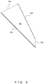
- FIG. 6 illustrates an example of a calculation method based on an area of a region between a feature line and a projection line.
- a line segment 601 connecting one end of the line segment 501 with one end of the line segment 502 and a line segment 602 connecting another end of the line segment 501 with another end of the line segment 502 are defined, an area Ai of a region surrounded by the line segments 501 , 502 , 601 , and 602 can be used as an error Ei.
- Ei Ai (2)
- the error Ei is smaller when the area Ai is smaller, and when the line 502 overlaps the line 501 , the error Ei becomes 0.
- T 1 denotes a threshold determined by a simulation etc.
- Score(i) 1
- Score(i) ⁇ 1 Accordingly, Score(i) becomes smaller when Ei is larger.
- the evaluation unit 319 determines whether an estimation has been successful or failed by comparing the sum S with a threshold T 2 .
- the sum S obtained by selecting any one of the associated pair sets 324 is equal to or larger than the threshold T 2 , the estimation is determined to be successful, and the sum S is less than the threshold T 2 for every associated pair set 324 selected, the estimation is determined to be a failure.
- T min denotes the minimum value of T 2 and N min denotes the minimum value of N.
- T min, N min, and the coefficient k are parameters determined by a simulation etc.
- a position or an orientation of an object or the imaging device 302 can be changed by a user moving the object or the imaging device 302 at will in a three-dimensional space.
- the user uses an input device such as a mouse to give an instruction of parallel shift and rotation of the 3D model 322 on the image 321 , and this makes intuitive inputs of instructions difficult.
- the changing unit 316 limits an axis of rotation of the 3D model 322 to a specific line and changes a position or an orientation of the 3D model 322 by rotating the 3D model 322 around the axis of rotation in accordance with the input instruction.
- the axis of rotation may be a line segment selected from plural line segments included in the 3D model 322 , or a normal line of a plane including the selected line segment and a viewpoint for the 3D model 322 as an example.
- FIG. 7 illustrates an example of a line segment of the 3D model 322 and a viewpoint.
- the horizontal direction of the image 321 is on the horizontal axis and the vertical direction of the image 321 is on the vertical axis.
- a 3D model 701 is a 3D model projected on the image 321 with a viewpoint 703 being a projection center, and a line segment 702 is a line segment selected from plural line segments included in the 3D model 322 .
- the line segment 702 or a normal line of a plane including the line segment 702 and the viewpoint 703 will be designated as an axis of rotation.
- FIG. 8A and FIG. 8B illustrate an example of an orientation of the 3D model 322 rotated around the designated axis of rotation.
- the rotational angle around the line segment 702 in FIG. 7 is ⁇ 1
- the rotational angle around a normal line that passes through the midpoint of the line segment 702 on a plane including the line segment 702 and the viewpoint 703 is ⁇ 2.
- ⁇ 1 and ⁇ 2 in orientations P1 to P3, those in orientations P11 to P13, those in orientations P21 to P23, and those in orientations P31 to P33 are provided below.
- the user can readily rotate the 3D model 322 and have the 3D model 322 overlap with the object on the image 321 .
- FIG. 9 illustrates an example of moving operations of a projection line at the time of rotating the 3D model 322 .
- a projection line 901 is a projection line of a selected line segment.
- the changing unit 316 resolves the moving vector 911 into a component 912 that is parallel to the projection line 901 and a component 913 that is perpendicular to the projection line 901 .
- the changing unit 316 converts the perpendicular component 913 into an amount of rotation ⁇ 1 around the selected line segment and also converts the parallel component 912 into an amount of rotation ⁇ 2 around a normal line of a plane including the selected line segment and a viewpoint.
- an amount of rotation that is proportional to the component 913 can be used as ⁇ 1
- an amount of rotation that is proportional to the component 912 can be used as ⁇ 2.
- the changing unit 316 causes the 3D model 322 to rotate around the selected line segment by ⁇ 1 and also causes the 3D model 322 to rotate around the normal line by ⁇ 2.
- FIG. 10 is a flowchart of the first specific example of image processing performed by the image processing apparatus 301 in FIG. 3 .
- the image obtaining unit 312 obtains an image 321 from the imaging device 302 (step 1001 ), and the detection unit 313 detects plural feature lines 323 from the image 321 (step 1002 ).
- the projection unit 314 obtains a position and an orientation of the 3D model 322 in a three-dimensional space (step 1003 ) and generates plural projection lines by projecting plural line segments of the 3D model 322 on the image 321 (step 1004 ).
- the projection unit 314 next, carries out hidden-line processing of the generated projection lines to eliminate hidden lines (step 1005 ).
- the display unit 315 displays, on a screen, the image 321 , the plural feature lines 323 , and plural projection lines representing the 3D model 322 .
- the generation unit 317 carries out associated pair generation processing to generate plural associated pairs from the plural feature lines 323 and the plural projection lines (step 1006 ) and generates plural associated pair sets 324 from the associated pairs (step 1007 ).
- the estimation unit 318 estimates a position and an orientation of the imaging device 302 by means of estimation processing by using the plural associated pair sets 324 and generates an estimation result 325 (step 1008 ).
- the evaluation unit 319 determines whether an estimation of the estimation processing has been successful or not (OK or not) (step 1009 ) and when the estimation was a failure (step 1009 , NO), the evaluation unit 319 outputs information indicating a failure in estimation.
- a user changes a position or an orientation of any of the object, the imaging device 302 , or the 3D model 322 on the image 321 , and the image processing apparatus 301 repeats the processing in step 1001 and subsequent processing.
- the image processing apparatus 301 ends the processing.
- FIG. 11 is a flowchart of an example of associated pair generation processing in step 1006 in FIG. 10 .
- the generation unit 317 calculates a distance and an angle between each of the feature lines 323 and each of the projection lines (step 1101 ).
- the generation unit 317 next, selects a feature line 323 or a projection line as a reference line segment and carries out filtering of candidate line segments by angle (step 1102 ).
- the generation unit 317 next, carries out filtering by distance (step 1103 ) and also carries out filtering by positional relationship (step 1104 ).
- the generation unit 317 selects, from among the remaining candidate line segments, a candidate line segment that is located in the shortest distance from the reference line segment, associates the selected candidate line segment with the reference line segment, and generates an associated pair (step 1105 ).
- the generation unit 317 generates plural associated pairs by carrying out the processing in steps 1102 to 1105 to each of the plural reference line segments. However, when a line segment on the object that corresponds to a projection line displayed on a screen is not detected as a feature line 323 or is detected as non-continuous plural feature lines 323 , an associated pair including the projection line is not always generated.
- FIG. 12 is a flowchart illustrating an example of estimation processing in step 1008 in FIG. 10 .
- the evaluation unit 319 selects an associated pair set 324 as a set for evaluation from among the plural associated pair sets 324 in descending order of error tolerance (step 1201 ).
- the estimation unit 318 estimates a position and an orientation of the imaging device 302 by using the set for evaluation and generates an estimation result 325 .
- the evaluation unit 319 By using the generated estimation result 325 , the evaluation unit 319 , next, generates N projection lines for evaluation by reprojecting, on the image 321 , line segments corresponding to N projection lines included in the plural associated pair sets 324 (step 1202 ).
- the evaluation unit 319 calculates errors E 1 to EN from N feature lines associated with the N projection lines and the N projection lines for evaluation (step 1203 ).
- the evaluation unit 319 next, calculates Score( 1 ) to Score(N) by using the equation (3), the equation (4) and the errors E 1 to EN (step 1204 ).
- the evaluation unit 319 next, calculates the sum S from the equation (5) by using Score( 1 ) to Score(N) and compares the sum S with a threshold T 2 (step 1206 ). When the sum S is less than the threshold T 2 (step 1206 , NO), the evaluation unit 319 checks whether all of the associated pair sets 324 are selected or not (step 1207 ). When there is any unselected associated pair set 324 remaining (step 1207 , NO), the image processing apparatus 301 repeats the processing in step 1201 and the subsequent processing to search for the next error-tolerant associated pair set 324 .
- the estimation unit 318 determines the estimation result 325 obtained from the set for evaluation to be the position and orientation of the imaging device 302 .
- the projection unit 314 projects plural line segments included in the 3D model 322 on the image 321 , and the display unit 315 superimposes the 3D model 322 on the image 321 .
- the evaluation unit 319 determines the estimation to be successful in step 1009 in FIG. 10 .
- the image processing apparatus 301 ends the processing.
- the evaluation unit 319 determines the estimation to be a failure in step 1009 in FIG. 10 .
- FIG. 13 is a flowchart of an example of changing processing carried out by the image processing apparatus 301 in FIG. 3 .
- the changing processing in FIG. 13 is carried out independently from the image processing in FIG. 10 .
- the changing unit 316 obtains a position and an orientation of the 3D model 322 in the three-dimensional space (step 1301 ) and receives a change instruction to change the 3D model 322 that is input by a user (step 1302 ).
- the changing unit 316 next, determines whether a constraint condition is applicable or not to the rotation operation of the 3D model 322 (step 1303 ). For example, when the change instruction includes a selection instruction that designate a specific line segment to be selected, the changing unit determines the constraint condition to be applicable, and when the change instruction does not include such a selection instruction, the changing unit determines the constraint condition to be not applicable.
- the changing unit 316 calculates an amount of change in consideration of the constraint (step 1304 ). For example, when the constraint condition includes a limitation to the axes of rotation as illustrated in FIG. 8A and FIG. 8B , in accordance with a moving operation included in a change instruction, the changing unit 316 resolves a moving vector into a component parallel to a projection line of the selected line segment and a component perpendicular to the projection line of the selected line segment, as illustrated in FIG. 9 . Afterwards, the changing unit 316 calculates an amount of rotation ⁇ 1 around the selected line and an amount of rotation ⁇ 2 around a normal line of a plane including the selected line segment and a viewpoint.
- the changing unit 316 calculates an amount of change without consideration of any constraint (step 1305 ). In this case, the changing unit 316 calculates an amount of rotation in accordance with a rotation operation included in the change instruction.
- the changing unit 316 next, changes a position and an orientation of the 3D model 322 by using the calculated amount of change (step 1306 ).
- the changing unit 316 causes the 3D model 322 to rotate around the selected line segment by ⁇ 1 and also causes the 3D model 322 to rotate around the normal line by ⁇ 2.
- the changing unit 316 rotates the 3D model 322 by the amount of rotation.
- the changing unit 316 repeats the processing in step 1301 and the subsequent steps.
- the changing unit 316 calculates an amount of shift of the parallel shift in step 1304 or step 1305 and causes the 3D model 322 to make the calculated amount of parallel shift.
- the projection unit 314 obtains the changed position and orientation of the 3D model 322 in step 1003 in FIG. 10 .
- FIG. 14 is a flowchart of the second specific example of image processing carried out by the image processing apparatus 301 in FIG. 3 .
- the processing in steps 1401 to 1409 is the same as the processing in steps 1001 to 1009 .
- the evaluation unit 319 When an estimation was a failure (step 1409 , NO), the evaluation unit 319 outputs information indicating a failure in estimation.
- a user changes a position or orientation of the 3D model 322 on the image 321 without changing a position and an orientation of an object and the imaging device 302 , and the image processing apparatus 301 repeats the processing in step 1403 and the subsequent steps. Consequently, the image 321 is not updated and the processing in steps 1403 to 1409 is carried out by using the same image 321 .
- FIG. 15A to FIG. 15C illustrate examples of the 3D model 322 superimposed on the image 321 based on the estimation result 325 .
- four feature lines that are in parallel to the horizontal direction and four feature lines that are in parallel to the vertical direction are included in an image 1501 of an object.
- four projection lines that are in parallel to the horizontal direction and four projection lines that are in parallel to the vertical direction are included in a shape 1502 to a shape 1504 that are the 3D model 322 of the object projected on the image 1501 .
- FIG. 15A illustrates an example of the shape 1502 superimposed on the image 1501 based on a correct estimation result 325 .
- FIG. 15B illustrates an example of the shape 1503 superimposed on an area of the upper right portion of the image 1501 based on an erroneous estimation result 325 .
- FIG. 15C illustrates an example of the shape 1504 superimposed on an area of the center portion of the image 1501 based on another erroneous estimation result 325 .
- FIG. 16 illustrates an example of image processing to restrain the operation of the estimation unit 318 .
- a shape 1601 to a shape 1604 represent shapes of the 3D model 322 projected on the image 1501 .
- the FIG. 1601 changes to the FIG. 1602 .
- the FIG. 1602 changes to the FIG. 1603 .
- FIG. 1603 when the FIG. 1603 is associated with the area of the upper right portion of the image 1501 , an erroneous estimation result 325 as illustrated in FIG. 15B may possibly be generated.
- the user therefore restrains the operation of the estimation unit 318 .
- the user is thereby able to further change the position of the 3D model 322 in depth direction, and the FIG. 1603 changes to the FIG. 1604 .
- the FIG. 1604 is correctly superimposed on the image 1501 , the user releases the restraint of the estimation unit 318 . In this manner, a correct estimation result 325 can be generated.
- FIG. 17 illustrates the second specific example of the image processing apparatus 101 in FIG. 1 .
- An image processing apparatus 1701 in FIG. 17 has the configuration of the image processing apparatus 301 in FIG. 3 but an estimation control unit 1711 is added so as to restrain the operation of the estimation unit 318 in accordance with an explicit restraint instruction given by a user.
- the estimation control unit 1711 restrains the operation of the estimation unit 318 estimating a position and an orientation of the imaging device 302 during a specific period of time in which the changing unit 316 changes the position or orientation of the 3D model 322 .
- This restraint of the operation of the estimation unit 318 prevents generation of an erroneous estimation result 325 from an erroneously associated pair generated during the change operation performed by the user. This restraint can therefore prevent the processing from being ended when the position is at a shifted position that is not intended by the user.
- the estimation control unit 1711 restrains the operation of the estimation unit 318 when a restraint instruction is input by a user.
- a restraint instruction a key operation of pressing down a specific key such as a control key may be used.
- the operation of the estimation unit 318 can be restrained. In this manner, the user can explicitly restrain the operation of the estimation unit 318 at the desired timing.
- FIG. 18 is a flowchart of the third specific example of the image processing carried out by the image processing apparatus 1701 in FIG. 17 .
- the processing in step 1801 to step 1805 and step 1807 to step 1810 is the same as the processing in step 1401 to step 1409 in FIG. 14 .
- the estimation control unit 1711 checks whether an restraint instruction is input by a user or not (step 1806 ).
- step 1806 When a restraint instruction is input (step 1806 , YES), the estimation control unit 1711 restrains the operation of the estimation unit 318 , and the image processing apparatus 1701 repeats the processing in step 1803 and the subsequent processing. On the other hand, when a restraint instruction is not input (step 1806 , NO), the estimation control unit 1711 releases the restraint of the estimation unit 318 , and the image processing apparatus 1701 carries out the processing in step 1807 and the subsequent processing.
- FIG. 19 illustrates the third specific example of the image processor apparatus 101 in FIG. 1 .
- the image processor apparatus 1901 in FIG. 19 has the configuration of the image processor apparatus 301 in FIG. 3 but an estimation control unit 1911 , an adjustment stage determination unit 1912 , and a sensitivity adjustment unit 1913 are added and automatically restrains the operation of the estimation unit 318 .
- the estimation control unit 1911 restrains the operation of the estimation unit 318 estimating a position and an orientation of the imaging device 302 during a specific period of time in which the changing unit 316 changes the position or orientation of the 3D model 322 .
- This restraint of the operation of the estimation unit 318 prevents generation of an erroneous estimation result 325 from an erroneously associated pair generated during the change operation performed by the user. This restraint can therefore prevent the processing from being ended when the position is at a shifted position that is not intended by the user.
- the adjustment stage determination unit 1912 determines whether rough adjustment or fine adjustment of the position or orientation of the 3D model 322 is carried out by the changing unit 316 .
- the estimation control unit 1911 restrains the operation of the estimation unit 318 and when the changing unit 316 carries out fine adjustment, the estimation control unit 1911 does not restrain the operation of the estimation unit 318 .
- generation of an estimation result 325 is restrained while a user carries out a rough change operation and the estimation result 325 can be generated at a point in time at which the user starts a fine change operation.
- the sensitivity adjustment unit 1913 lowers the change sensitivity G of a position or orientation of the 3D model 322 subjected to the change operation when the changing unit 316 carries out the fine adjustment than when the changing unit 316 carries out the rough adjustment.
- the coordinate X and the coordinate Y can be represented in accordance with the following equations.
- X ( x ⁇ cx )* Z/f (11)
- Y ( y ⁇ cy )* Z/f (12)
- Z represents the coordinate in depth direction in the camera coordinate system
- f represents a focal distance
- (cx, cy) represents a coordinate of the image center on the screen.
- f and (cx, cy) are internal parameters of the imaging device 302 .
- a relation between an amount of operation LP of an operation pointer on the screen and an amount of movement LM of the 3D model 322 in the three-dimensional space can be represented in accordance with the following equation by using a coefficient of the amount of movement C and the change sensitivity G.
- LM LP*C*G (13)
- the amount of operation LP represents an amount of movement (the number of pixels) of the operation pointer in the x direction or in the y direction
- the amount of movement LM represents an amount of movement of the 3D model 322 in the X direction or in the Y direction.
- the coefficient of the amount of movement C may be set to (Z/f)*Q. Then even when a distance in depth direction changes, the operation feeling of a user does not change.
- the constant Q can be determined by experiments.
- FIG. 20 illustrates an example of a change in the amount of operation over time.
- time is on the horizontal axis and the amount of operation is on the vertical axis.
- a curve line 2001 represents a change in the amount of operation over time.
- a change in the amount of operation is large in a time period 2011 on the curve line 2001 , and in this period, a change operation of the rough adjustment is carried out.
- a change in the amount of operation is small in a time period 2012 on the curve line 2001 , and in this period, a change operation of the fine adjustment is carried out.
- the sensitivity adjustment unit 1913 records the amount of operation in the change operation carried out by a user and adjusts the change sensitivity G based on a change in the amount of operation over time.
- a method of adjusting the change sensitivity G a possible method is provided below as an example.
- the sensitivity adjustment unit 1913 calculates a ratio of the amount of operation in a most recent specific period of time to the amount of operation in the specific period of time in the early stage of the operation or the amount of operation in the specific period of time before a defined time from the current time.
- the sensitivity adjustment unit 1913 make a change in the change sensitivity G in accordance with the calculated ratio.
- the sensitivity adjustment unit 1913 makes a change in the change sensitivity G in accordance with the amount of operation in a most recent specific period of time.
- the time period 2011 corresponds to a specific period of time in the early stage of the operation and the time period 2012 corresponds to the most recent specific period of time.
- FIG. 21 illustrates the first sensitivity adjustment method.
- a ratio of the amount of operation within the most recent 1 second to the amount of operation within 1 second in the early stage of the operation is on the horizontal axis, and the change sensitivity G is on the vertical axis.
- a curve line 2101 represents values of the change sensitivity G in accordance with the ratio of the amount of operation.
- the change sensitivity G When the ratio of the amount of operation is r1 or less, the change sensitivity G is g0, and when the ratio of the amount of operation is r2 or more, the change sensitivity G is 1. In a range where the ratio of the amount of operation is between r1 and r2, the change sensitivity G increases linearly from g0 to 1. As an example, g0 may be any value in a range from 0.1 to 0.3.
- r1 and r2 may be a ratio obtained from the size of the image 321 or may be fixed values independent of the size of the image 321 .
- FIG. 22 illustrates the second sensitivity adjustment method.
- a ratio of the amount of operation within the most recent 1 second to the amount of operation within 1 second in the early stage of the operation is on the horizontal axis and the change sensitivity G is on the vertical axis.
- a curve line 2201 represents values of the change sensitivity G in accordance with the ratio of the amount of operation.
- the change sensitivity G increases stepwise from g0 to 1 in a range where the ratio of the amount of operation is between r1 and r2.
- another non-linear function such as the logarithmic function may be used.
- FIG. 23 illustrates the third sensitivity adjustment method.
- the amount of operation within the most recent 1 second is on the horizontal axis and the change sensitivity G is on the vertical axis.
- a curve line 2301 represents values of the change sensitivity G in accordance with the amount of operation.
- the change sensitivity G When the amount of operation is h1 pixels or less, the change sensitivity G is g0 and when the amount of operation is h2 pixels or more, the change sensitivity G is 1. In a range where the amount of operation is between h1 pixels and h2 pixels, the change sensitivity G increases linearly from g0 to 1.
- h1 and h2 may be the number of pixels obtained from the size of the image 321 or may be fixed values independent of the size of the image 321 .
- h1 may be 5% of the number of pixels of the width of the image 321 and h2 may be 10% of the number of pixels of the width of the image 321 .
- the change sensitivity G may be set to either g0 or 1.
- FIG. 24 illustrates the fourth sensitivity adjustment method.
- the amount of operation within the most recent 1 second is on the horizontal axis and the change sensitivity G is on the vertical axis.
- a curve line 2401 represents values of the change sensitivity G in accordance with the amount of operation.
- the change sensitivity G increases stepwise from g0 to 1 in a range where the amount of operation is between h1 pixels and h2 pixels.
- another non-linear function such as the logarithmic function may be used.
- the change sensitivity G can be displayed by changing a display mode of an operation pointer.
- the display unit 315 displays the operation pointer of the change operation on the screen and changes the display mode of the operation pointer in accordance with the change sensitivity G. This enables a user to visually recognize a change in the change sensitivity G.
- the change in the display mode can be changes in size, shape, color, or others.
- FIG. 25A to FIG. 25C illustrate examples of an operation pointer in the rough adjustment.
- a FIG. 2501 to a FIG. 2503 represent figures of the 3D model 322 projected on the image 1501 .
- FIG. 25A illustrates an operation pointer 2511 when the FIG. 2501 is displayed on a position that is shifted from the image 1501 .
- FIG. 25B illustrates an operation pointer 2512 when the FIG. 2502 is superimposed on an area of the upper right portion of the image 1501 .
- FIG. 25C illustrates an operation pointer 2513 when the FIG. 2503 , which is larger than the FIG. 2502 , is superimposed on the area of the upper right portion of the image 1501 .
- the operation pointer 2511 to the operation pointer 2513 are displayed in the same size.
- FIG. 26 illustrates an example of an operation pointer in the fine adjustment.
- a FIG. 2601 represents a figure of the 3D model 322 projected on the image 1501 .
- An operation pointer 2611 in the fine adjustment is displayed smaller in size than the operation pointer 2511 to the operation pointer 2513 in the rough adjustment.
- the size of the operation pointer may be continuously changed in accordance with the change sensitivity G.
- the shape or the color of the operation pointer may be continuously changed in accordance with the change sensitivity G.
- the changing unit 316 changes the position or orientation of the 3D model 322 in accordance with the change operation of a user, and the adjustment stage determination unit 1912 determines whether the changing unit 316 carries out the rough adjustment or the fine adjustment in accordance with the amount of operation in the change operation.
- the adjustment stage determination unit 1912 determines the adjustment that the changing unit 316 is carrying out to be the rough adjustment when the ratio of the amount of operation in the sensitivity adjustment method in (A) or the amount of operation in a most recent specific period of time in the sensitivity adjustment method in (B) is larger than a threshold.
- the adjustment stage determination unit 1921 determines the adjustment that the changing unit 316 is carrying out to be the fine adjustment when the ratio of the amount of operation or the amount of operation in the most recent specific period of time is equal to or less than a threshold.
- the estimation unit 318 determines the position and the orientation of the imaging device 302 based on the figure selected by the user.
- the estimation unit 318 may identify any one candidate, and the user may change the identified candidate to another candidate.
- the display unit 315 superimposes and displays a figure indicating the 3D model 322 corresponding to the candidate identified by the estimation unit 318 on the image 321 and also displays candidate information indicating that plural candidates exist.
- the display unit 315 When a candidate change instruction is input by the user, the display unit 315 superimposes and displays figures indicating the 3D model 322 corresponding to respective candidates on the image 321 , and the user selects any one of the figures.
- the estimation unit 318 determines the position and the orientation of the imaging device 302 based on the figure selected by the user.
- FIG. 27A and FIG. 27B are flowcharts of the fourth specific example of the image processing carried out by the image processor apparatus 1901 in FIG. 19 .
- a candidate of the position and the orientation of the imaging device 302 is designated by a user from among plural candidates.
- the processing in step 2701 to step 2705 and step 2707 to step 2710 is the same as the processing in step 1401 to step 1409 in FIG. 14 .
- step 2709 the estimation processing in step 2709 is slightly different from the estimation processing in FIG. 12 .
- the evaluation unit 319 calculates the sum S by selecting all the associated pair sets 324 in sequence and compares the calculated sum S with the threshold T 2 .
- the evaluation unit 319 determines the estimation to be successful in step 2710 .
- the estimation unit 318 determines the estimation result 325 obtained in accordance with the associated pair set 324 to be the position and the orientation of the imaging device 302 .
- the estimation unit 318 determines the plural estimation results 325 obtained in accordance with those associated pair sets 324 to be plural candidates of the position and the orientation of the imaging device 302 .
- the adjustment stage determination unit 1912 determines whether the changing unit 316 carries out the fine adjustment or not (step 2706 ).
- step 2706 , NO When the changing unit 316 carries out the rough adjustment (step 2706 , NO), the estimation control unit 1911 restrains the operation of the estimation unit 318 , and the image processing apparatus 1901 repeats the processing in step 2703 and the subsequent processing.
- step 2706 , YES when the changing unit 316 carries out the fine adjustment (step 2706 , YES), the estimation control unit 1911 releases the restraint of the estimation unit 318 , and the image processing apparatus 1901 carries out the processing in step 2707 and the subsequent processing.
- the estimation unit 318 checks whether plural candidates were generated or not (step 2711 ).
- the display unit 315 superimposes and displays figures indicating the 3D model 322 corresponding to the respective candidates on the image 321 (step 2712 ).
- the estimation unit 318 determines the estimation result of the candidate corresponding to a figure selected by a user from among the plural figures to be the position and the orientation of the imaging device 302 (step 2713 ).
- the projection unit 314 projects plural line segments included in the 3D model 322 on the image 321 by using the determined position and the determined orientation of the imaging device 302 , and the display unit 315 superimposes the 3D model 322 on the image 321 .
- the image processing apparatus 1901 ends the processing.
- the most suitable candidate can be designated by a user himself/herself from among plural candidates generated by the fine adjustment to determine the position and the orientation of the imaging device 302 .
- FIG. 28 is a flowchart of sensitivity adjustment processing carried out by the image processing apparatus 1901 in FIG. 19 .
- the sensitivity adjustment processing in FIG. 28 is executed independently of the image processing in FIG. 27A and FIG. 27B .
- the sensitivity adjustment unit 1913 first, adjusts the change sensitivity G based on the amount of operation in the change operation carried out by a user (step 2801 ).
- the display unit 315 displays the change sensitivity G by changing a display mode of an operation pointer in accordance with the adjustment change sensitivity G (step 2802 ).
- the changing unit 316 calculates a position and an orientation of the 3D model 322 (step 2803 ) by carrying out the same processing as the processing in step 1301 to step 1306 in FIG. 13 , and the sensitivity adjustment unit 1913 determines whether the processing is to be ended or not (step 2804 ).
- the sensitivity adjustment unit 1913 determines the processing to be ended and determines the processing not to be ended when the image processing has not yet ended.
- the image processing apparatus 1901 repeats the processing in step 2801 and the subsequent processing.
- the sensitivity adjustment unit 1913 determines the processing to be ended (step 2804 , YES)
- the image processing apparatus 1901 ends the processing.
- FIG. 29A and FIG. 29B are flowcharts of the fifth specific example of the image processing carried out by the image processing apparatus 1901 in FIG. 19 .
- any one candidate from among plural candidates of a position and an orientation of the imaging device 302 is identified by the estimation unit 318 .
- the processing in step 2901 to step 2910 is the same as the processing in step 2701 to step 2710 in FIG. 27A .
- the estimation unit 318 checks whether plural candidates were generated or not (step 2911 ). When plural candidates were generated (step 2911 , YES), the estimation unit 318 identifies a candidate corresponding to the associated pair set 324 that has the largest sum S from among the plural candidates.
- the display unit 315 superimposes the figure indicating the 3D model 322 corresponding to the identified candidate on the image 321 and displays candidate information indicating that plural candidates exist and a change button (step 2912 ). By pressing the displayed change button, a user can input a candidate change instruction to the image processing apparatus 1901 .
- the estimation unit 318 checks whether a candidate change instruction is input from a user or not (step 2913 ).
- a candidate change instruction is input (step 2913 , YES)
- the display unit 315 superimposes and displays figures indicating the 3D model 322 corresponding to respective candidates on the image 321 (step 2914 ).
- the estimation unit 318 determines the estimation result 325 of the candidate corresponding to the figure selected by the user from among the figures to be an position and an orientation of the imaging device 302 .
- the projection unit 314 projects plural line segments included in the 3D model 322 on the image 321 by using the determined position and the determined orientation of the imaging device 302 , and the display unit 315 superimposes the 3D model 322 on the image 321 .
- the image processing apparatus 1901 ends the processing.
- the estimation unit 318 checks whether a specific period of time has elapsed since the start of the display of the candidate information or not (step 2916 ). When the specific period of time has not elapsed (step 2916 , NO), the image processing apparatus 1901 repeats the processing in step 2912 and the subsequent processing. When the specific period of time has elapsed (step 2916 , YES), the image processing apparatus 1901 ends the processing.
- the configurations of the image processing apparatuses in FIG. 1 , FIG. 3 , FIG. 17 and FIG. 19 are merely examples of configurations, and some components may be omitted or changed depending on the use or conditions of the image processing apparatuses.
- the display unit 315 may be omitted.
- the changing unit 316 may be omitted.
- the changing unit 316 may be omitted.
- shape information representing a shape of an object may be used as a 3D model 322 .
- the image 321 is not limited to an image obtained from the imaging device 302 , but may be an image stored in the storage unit 311 in advance or may be an image obtained from an external device over a communication network.
- the sensitivity adjustment unit 1913 can be omitted.
- FIG. 2 , FIG. 10 to FIG. 14 , FIG. 18 and FIG. 27A to FIG. 29B are merely examples, and some steps of the processing may be omitted or changed depending on the configuration or conditions of the image processing apparatus.
- any of the filtering in steps 1102 to 1104 may be omitted.
- the changing processing in FIG. 13 may be omitted.
- the 3D model, the projection lines, and the feature lines illustrated in FIG. 4 , FIG. 7 , FIG. 8A and FIG. 8B are merely examples, and the 3D model, the projection lines, and the feature lines change depending on an object to be imaged.
- Orientations of the 3D model illustrated in FIG. 8A and FIG. 8B are merely examples, and orientations of the 3D model change depending on the amount of rotation designated by a change instruction.
- the moving operation illustrated in FIG. 9 is merely an example, and a user may input a moving vector in other methods.
- Images and figures illustrated in FIG. 15A to FIG. 15C , FIG. 16 , FIG. 25A to FIG. 25C and FIG. 26 are merely examples, and images and figures change depending on an object to be imaged.
- the amount of operation in FIG. 20 is merely an example, and the amount of operation changes depending on the change operation of a user.
- the sensitivity adjustment methods in FIG. 21 to FIG. 24 are merely examples, and other sensitivity adjustment methods may be used depending on the configuration or conditions of the image processing apparatus.
- the calculating equations of the equations (1) to (13) are merely examples, and other calculating equations may be used depending on the configuration or conditions of the image processing apparatus.
- FIG. 30 illustrates an example of the hardware configuration of an information processing apparatus (computer) used as the image processing apparatuses in FIG. 1 , FIG. 3 , FIG. 17 and FIG. 19 .
- the information processing apparatus in FIG. 30 includes a central processing unit (CPU) 3001 , a memory 3002 , an input device 3003 , an output device 3004 , an auxiliary storage device 3005 , a medium driver device 3006 , and a network connector device 3007 . These components are hardware and coupled to each other by a bus 3008 .
- the imaging device 302 in FIG. 3 , FIG. 17 , and FIG. 19 may be coupled to the bus 3008 .
- the memory 3002 is, for example, a semiconductor memory such as a read only memory (ROM), a random access memory (RAM), and a flash memory and stores programs and data used for processing.
- the memory 3002 can be used as a storage unit 111 in FIG. 1 or a storage unit 311 in FIG. 3 , FIG. 17 and FIG. 19 .
- CPU 3001 operates, for example, as the detection unit 112 , the projection unit 113 , the generation unit 114 , the estimation unit 115 , and the evaluation unit 116 in FIG. 1 by executing programs using the memory 3002 .
- CPU 3001 also operates as the image obtaining unit 312 , the detection unit 313 , the projection unit 314 , the changing unit 316 , the generation unit 317 , the estimation unit 318 , and the evaluation unit 319 in FIG. 3 , FIG. 17 and FIG. 19 by executing programs using the memory 3002 .
- CPU 3001 also operates as the estimation control unit 1711 in FIG. 17 by executing programs using the memory 3002 .
- CPU 3001 also operates as the estimation control unit 1911 , the adjustment stage determination unit 1912 , and the sensitivity adjustment unit 1913 in FIG. 19 by executing programs using the memory 3002 .
- the input device 3003 is, for example, a keyboard, a pointing device and the like and is used for inputting instructions or data from an operator or a user.
- the output device 3004 is, for example, a display device, a printer, a speaker, and the like and is used for outputting inquiries Or instructions to the operator or the user and for outputting processing results.
- the processing results may be an estimation result 325 or may be a 3D model 322 superimposed on an image 321 .
- the output device 3004 may be used as the display unit 315 in FIG. 3 , FIG. 17 , and FIG. 19 .
- the auxiliary storage device 3005 is, for example, a magnetic disk device, an optical disk device, a magneto optical disk device, a tape device, and the like.
- the auxiliary storage device 3005 may be a hard disk drive or a flash memory.
- the information processing apparatus can store programs and data in the auxiliary storage device 3005 and loads them into the memory 3002 at the point of use.
- the auxiliary storage device 3005 may be used as the storage unit 111 in FIG. 1 or the storage unit 311 in FIG. 3 , FIG. 17 and FIG. 19 .
- the medium driver device 3006 drives a portable recording medium 3009 and accesses to the recorded contents.
- the portable recording medium 3009 is a memory device, a flexible disk, an optical disk, a magneto optical disk, and the like.
- the portable recording medium 3009 may be a compact disk read only memory (CD-ROM), a digital versatile disk (DVD), a universal serial bus (USB) memory, and the like.
- CD-ROM compact disk read only memory
- DVD digital versatile disk
- USB universal serial bus
- a computer-readable recording medium that stores programs and data used for processing such as the memory 3002 , the auxiliary storage device 3005 , or the portable recording medium 3009 is a physical (non-transitory) recording medium.
- the network connector device 3007 is a communication interface circuit that is coupled to a communication network such as a local area network (LAN), a wide area network (WAN) and the like and that allows data exchange for communications.
- the information processing apparatus can receive programs and data from an external device via the network connector device 3007 and can load them into the memory 3002 at the time of use.
- the information processing apparatus does not need to include all of the components in FIG. 30 , but some components may be omitted depending on the use or conditions.
- the medium driver device 3006 or the network connector device 3007 can be omitted.
Abstract
Description
- Patent Document 1: Japanese Laid-open Patent Publication No. 2017-91078
- Patent Document 2: Japanese Laid-open Patent Publication No. 2018-67188
- Non-patent Document 1: R. Kumar et al., “Robust Methods for Estimating Pose and a Sensitivity Analysis”, CVGIP: Image Understanding Volume 60,
Issue 3, pages 313-342, November 1994 - Non-patent Document 2: J. Z. C. Lai, “Sensitivity Analysis of Line Correspondence”, IEEE Transactions on Systems, Man, and Cybernetics VOL. 25, NO. 6, pages 1016-1023, 1995
Ei=Li1+Li2 (1)
Ei=Ai (2)
Score(i)=1(Ei<T1) (3)
Score(i)=(T1/Ei)2(Ei≥T1) (4)
S=Σ i=1 N Score(i) (5)
T2=T min+k×(N−N min) (6)
X=(x−cx)*Z/f (11)
Y=(y−cy)*Z/f (12)
LM=LP*C*G (13)
Claims (20)
Applications Claiming Priority (6)
| Application Number | Priority Date | Filing Date | Title |
|---|---|---|---|
| JPJP2018-233684 | 2018-12-13 | ||
| JP2018-233684 | 2018-12-13 | ||
| JP2018233684 | 2018-12-13 | ||
| JPJP2019-193142 | 2019-10-24 | ||
| JP2019193142A JP2020098575A (en) | 2018-12-13 | 2019-10-24 | Image processor, method for processing information, and image processing program |
| JP2019-193142 | 2019-10-24 |
Publications (2)
| Publication Number | Publication Date |
|---|---|
| US20200193637A1 US20200193637A1 (en) | 2020-06-18 |
| US11138759B2 true US11138759B2 (en) | 2021-10-05 |
Family
ID=71071730
Family Applications (1)
| Application Number | Title | Priority Date | Filing Date |
|---|---|---|---|
| US16/708,951 Active 2040-03-31 US11138759B2 (en) | 2018-12-13 | 2019-12-10 | Image processing apparatus and image processing method |
Country Status (1)
| Country | Link |
|---|---|
| US (1) | US11138759B2 (en) |
Families Citing this family (3)
| Publication number | Priority date | Publication date | Assignee | Title |
|---|---|---|---|---|
| KR102225342B1 (en) * | 2019-02-13 | 2021-03-09 | 주식회사 브이터치 | Method, system and non-transitory computer-readable recording medium for supporting object control |
| US10832444B2 (en) * | 2019-02-18 | 2020-11-10 | Nec Corporation Of America | System and method for estimating device pose in a space |
| US11657506B2 (en) * | 2019-03-06 | 2023-05-23 | General Electric Company | Systems and methods for autonomous robot navigation |
Citations (12)
| Publication number | Priority date | Publication date | Assignee | Title |
|---|---|---|---|---|
| US7298923B2 (en) * | 2003-11-03 | 2007-11-20 | Siemens Medical Solutions Usa, Inc. | Method and system for focus-adaptive reconstruction of spine images |
| US8306260B2 (en) * | 2005-07-07 | 2012-11-06 | Ingenious Targeting Laboratory, Inc. | System for 3D monitoring and analysis of motion behavior of targets |
| US8417060B2 (en) * | 2006-03-20 | 2013-04-09 | Arizona Board Of Regents For And On Behalf Of Arizona State University | Methods for multi-point descriptors for image registrations |
| JP2013149042A (en) | 2012-01-18 | 2013-08-01 | Hitachi Plant Technologies Ltd | Facility maintenance management system |
| US8682106B2 (en) * | 2007-06-14 | 2014-03-25 | Canon Kabushiki Kaisha | Method and apparatus for measuring position and orientation of an object |
| JP2014091078A (en) | 2012-11-02 | 2014-05-19 | Mitsubishi Heavy Ind Ltd | Sealant coating brush, and sealant coating method |
| US9091528B2 (en) * | 2004-12-23 | 2015-07-28 | General Electric Company | System and method for object measurement |
| US9530212B2 (en) * | 2013-12-20 | 2016-12-27 | Huawei Technologies Co., Ltd. | Image frame conversion method and video frame conversion method and apparatus |
| US20170132752A1 (en) | 2015-11-06 | 2017-05-11 | Fujitsu Limited | Superimposed display method and superimposed display apparatus |
| US9747680B2 (en) * | 2013-11-27 | 2017-08-29 | Industrial Technology Research Institute | Inspection apparatus, method, and computer program product for machine vision inspection |
| JP2018067188A (en) | 2016-10-20 | 2018-04-26 | 日本電信電話株式会社 | Camera information correction device, camera information correction method, and camera information correction program |
| JP2018073095A (en) | 2016-10-28 | 2018-05-10 | キヤノン株式会社 | Image processing device and image processing method |
-
2019
- 2019-12-10 US US16/708,951 patent/US11138759B2/en active Active
Patent Citations (12)
| Publication number | Priority date | Publication date | Assignee | Title |
|---|---|---|---|---|
| US7298923B2 (en) * | 2003-11-03 | 2007-11-20 | Siemens Medical Solutions Usa, Inc. | Method and system for focus-adaptive reconstruction of spine images |
| US9091528B2 (en) * | 2004-12-23 | 2015-07-28 | General Electric Company | System and method for object measurement |
| US8306260B2 (en) * | 2005-07-07 | 2012-11-06 | Ingenious Targeting Laboratory, Inc. | System for 3D monitoring and analysis of motion behavior of targets |
| US8417060B2 (en) * | 2006-03-20 | 2013-04-09 | Arizona Board Of Regents For And On Behalf Of Arizona State University | Methods for multi-point descriptors for image registrations |
| US8682106B2 (en) * | 2007-06-14 | 2014-03-25 | Canon Kabushiki Kaisha | Method and apparatus for measuring position and orientation of an object |
| JP2013149042A (en) | 2012-01-18 | 2013-08-01 | Hitachi Plant Technologies Ltd | Facility maintenance management system |
| JP2014091078A (en) | 2012-11-02 | 2014-05-19 | Mitsubishi Heavy Ind Ltd | Sealant coating brush, and sealant coating method |
| US9747680B2 (en) * | 2013-11-27 | 2017-08-29 | Industrial Technology Research Institute | Inspection apparatus, method, and computer program product for machine vision inspection |
| US9530212B2 (en) * | 2013-12-20 | 2016-12-27 | Huawei Technologies Co., Ltd. | Image frame conversion method and video frame conversion method and apparatus |
| US20170132752A1 (en) | 2015-11-06 | 2017-05-11 | Fujitsu Limited | Superimposed display method and superimposed display apparatus |
| JP2018067188A (en) | 2016-10-20 | 2018-04-26 | 日本電信電話株式会社 | Camera information correction device, camera information correction method, and camera information correction program |
| JP2018073095A (en) | 2016-10-28 | 2018-05-10 | キヤノン株式会社 | Image processing device and image processing method |
Non-Patent Citations (2)
| Title |
|---|
| Jim Z. C. Lai, "Sensitivity Analysis of Line Correspondence", IEEE Transactions on Systems, Man, and Cybernetics, vol. 25, No. 6, Jun. 1995, pp. 1016-1023 (8 pages). |
| Rakesh Kumar et al., "Robust Methods for Estimating Pose and a Sensitivity Analysis", CVGIP: Image Understanding vol. 60, No. 3, Nov. 1994, pp. 313-342 (30 pages). |
Also Published As
| Publication number | Publication date |
|---|---|
| US20200193637A1 (en) | 2020-06-18 |
Similar Documents
| Publication | Publication Date | Title |
|---|---|---|
| US11138759B2 (en) | Image processing apparatus and image processing method | |
| US10354402B2 (en) | Image processing apparatus and image processing method | |
| US8368768B2 (en) | Image processing apparatus, image processing method, and program | |
| JP7188201B2 (en) | Image processing device, image processing method, and image processing program | |
| US10311576B2 (en) | Image processing device and image processing method | |
| JP2016212784A (en) | Image processing apparatus and image processing method | |
| US10930068B2 (en) | Estimation apparatus, estimation method, and non-transitory computer-readable storage medium for storing estimation program | |
| JP2020098575A (en) | Image processor, method for processing information, and image processing program | |
| JP4560023B2 (en) | Image matching apparatus, image matching program, and image matching method | |
| US9582896B2 (en) | Line tracking with automatic model initialization by graph matching and cycle detection | |
| WO2019093457A1 (en) | Information processing device, information processing method and program | |
| US11145048B2 (en) | Image processing apparatus, image processing method, and non-transitory computer-readable storage medium for storing program | |
| JP2020134242A (en) | Measuring method, measuring device and program | |
| US10755439B2 (en) | Estimation device, estimation method and storage medium | |
| JP7232663B2 (en) | Image processing device and image processing method | |
| JP4321251B2 (en) | Apparatus and method for generating and displaying composite image | |
| JP2006215657A (en) | Method, apparatus, program and program storage medium for detecting motion vector | |
| US20200034650A1 (en) | Measurement apparatus, measurement method, and computer-readable recording medium storing measurement program | |
| WO2023179342A1 (en) | Relocalization method and related device | |
| JP5636966B2 (en) | Error detection apparatus and error detection program | |
| US20230162391A1 (en) | Method for estimating three-dimensional hand pose and augmentation system | |
| CN107507224B (en) | Moving object detection method, device, medium and computing device |
Legal Events
| Date | Code | Title | Description |
|---|---|---|---|
| AS | Assignment |
Owner name: FUJITSU LIMITED, JAPAN Free format text: ASSIGNMENT OF ASSIGNORS INTEREST;ASSIGNORS:KARASUDANI, AYU;MOTEKI, ATSUNORI;KURAKI, KENSUKE;AND OTHERS;SIGNING DATES FROM 20191205 TO 20191209;REEL/FRAME:051242/0071 |
|
| FEPP | Fee payment procedure |
Free format text: ENTITY STATUS SET TO UNDISCOUNTED (ORIGINAL EVENT CODE: BIG.); ENTITY STATUS OF PATENT OWNER: LARGE ENTITY |
|
| STPP | Information on status: patent application and granting procedure in general |
Free format text: DOCKETED NEW CASE - READY FOR EXAMINATION |
|
| STPP | Information on status: patent application and granting procedure in general |
Free format text: NOTICE OF ALLOWANCE MAILED -- APPLICATION RECEIVED IN OFFICE OF PUBLICATIONS |
|
| STPP | Information on status: patent application and granting procedure in general |
Free format text: PUBLICATIONS -- ISSUE FEE PAYMENT VERIFIED |
|
| STCF | Information on status: patent grant |
Free format text: PATENTED CASE |