EP3165682A2 - Quick hitch - Google Patents
Quick hitch Download PDFInfo
- Publication number
- EP3165682A2 EP3165682A2 EP16191790.1A EP16191790A EP3165682A2 EP 3165682 A2 EP3165682 A2 EP 3165682A2 EP 16191790 A EP16191790 A EP 16191790A EP 3165682 A2 EP3165682 A2 EP 3165682A2
- Authority
- EP
- European Patent Office
- Prior art keywords
- quick hitch
- securing means
- link
- axis
- pivotable member
- Prior art date
- Legal status (The legal status is an assumption and is not a legal conclusion. Google has not performed a legal analysis and makes no representation as to the accuracy of the status listed.)
- Granted
Links
- 230000011664 signaling Effects 0.000 claims description 18
- 241001236644 Lavinia Species 0.000 description 5
- 230000006835 compression Effects 0.000 description 3
- 238000007906 compression Methods 0.000 description 3
- 230000000295 complement effect Effects 0.000 description 2
- 239000007787 solid Substances 0.000 description 2
- 229910000831 Steel Inorganic materials 0.000 description 1
- 238000010276 construction Methods 0.000 description 1
- 238000009434 installation Methods 0.000 description 1
- 239000007769 metal material Substances 0.000 description 1
- 239000010959 steel Substances 0.000 description 1
Images


Classifications
-
- E—FIXED CONSTRUCTIONS
- E02—HYDRAULIC ENGINEERING; FOUNDATIONS; SOIL SHIFTING
- E02F—DREDGING; SOIL-SHIFTING
- E02F3/00—Dredgers; Soil-shifting machines
- E02F3/04—Dredgers; Soil-shifting machines mechanically-driven
- E02F3/28—Dredgers; Soil-shifting machines mechanically-driven with digging tools mounted on a dipper- or bucket-arm, i.e. there is either one arm or a pair of arms, e.g. dippers, buckets
- E02F3/36—Component parts
- E02F3/3604—Devices to connect tools to arms, booms or the like
- E02F3/3609—Devices to connect tools to arms, booms or the like of the quick acting type, e.g. controlled from the operator seat
- E02F3/3631—Devices to connect tools to arms, booms or the like of the quick acting type, e.g. controlled from the operator seat with a hook and a transversal locking element
-
- E—FIXED CONSTRUCTIONS
- E02—HYDRAULIC ENGINEERING; FOUNDATIONS; SOIL SHIFTING
- E02F—DREDGING; SOIL-SHIFTING
- E02F3/00—Dredgers; Soil-shifting machines
- E02F3/04—Dredgers; Soil-shifting machines mechanically-driven
- E02F3/28—Dredgers; Soil-shifting machines mechanically-driven with digging tools mounted on a dipper- or bucket-arm, i.e. there is either one arm or a pair of arms, e.g. dippers, buckets
- E02F3/36—Component parts
- E02F3/3604—Devices to connect tools to arms, booms or the like
- E02F3/3609—Devices to connect tools to arms, booms or the like of the quick acting type, e.g. controlled from the operator seat
-
- E—FIXED CONSTRUCTIONS
- E02—HYDRAULIC ENGINEERING; FOUNDATIONS; SOIL SHIFTING
- E02F—DREDGING; SOIL-SHIFTING
- E02F3/00—Dredgers; Soil-shifting machines
- E02F3/04—Dredgers; Soil-shifting machines mechanically-driven
- E02F3/28—Dredgers; Soil-shifting machines mechanically-driven with digging tools mounted on a dipper- or bucket-arm, i.e. there is either one arm or a pair of arms, e.g. dippers, buckets
- E02F3/36—Component parts
- E02F3/3604—Devices to connect tools to arms, booms or the like
- E02F3/3609—Devices to connect tools to arms, booms or the like of the quick acting type, e.g. controlled from the operator seat
- E02F3/3618—Devices to connect tools to arms, booms or the like of the quick acting type, e.g. controlled from the operator seat with two separating hooks
-
- E—FIXED CONSTRUCTIONS
- E02—HYDRAULIC ENGINEERING; FOUNDATIONS; SOIL SHIFTING
- E02F—DREDGING; SOIL-SHIFTING
- E02F3/00—Dredgers; Soil-shifting machines
- E02F3/04—Dredgers; Soil-shifting machines mechanically-driven
- E02F3/28—Dredgers; Soil-shifting machines mechanically-driven with digging tools mounted on a dipper- or bucket-arm, i.e. there is either one arm or a pair of arms, e.g. dippers, buckets
- E02F3/36—Component parts
- E02F3/3604—Devices to connect tools to arms, booms or the like
- E02F3/3609—Devices to connect tools to arms, booms or the like of the quick acting type, e.g. controlled from the operator seat
- E02F3/3627—Devices to connect tools to arms, booms or the like of the quick acting type, e.g. controlled from the operator seat with a hook and a longitudinal locking element
-
- E—FIXED CONSTRUCTIONS
- E02—HYDRAULIC ENGINEERING; FOUNDATIONS; SOIL SHIFTING
- E02F—DREDGING; SOIL-SHIFTING
- E02F3/00—Dredgers; Soil-shifting machines
- E02F3/04—Dredgers; Soil-shifting machines mechanically-driven
- E02F3/28—Dredgers; Soil-shifting machines mechanically-driven with digging tools mounted on a dipper- or bucket-arm, i.e. there is either one arm or a pair of arms, e.g. dippers, buckets
- E02F3/36—Component parts
- E02F3/3604—Devices to connect tools to arms, booms or the like
- E02F3/3609—Devices to connect tools to arms, booms or the like of the quick acting type, e.g. controlled from the operator seat
- E02F3/364—Devices to connect tools to arms, booms or the like of the quick acting type, e.g. controlled from the operator seat using wedges
-
- E—FIXED CONSTRUCTIONS
- E02—HYDRAULIC ENGINEERING; FOUNDATIONS; SOIL SHIFTING
- E02F—DREDGING; SOIL-SHIFTING
- E02F3/00—Dredgers; Soil-shifting machines
- E02F3/04—Dredgers; Soil-shifting machines mechanically-driven
- E02F3/28—Dredgers; Soil-shifting machines mechanically-driven with digging tools mounted on a dipper- or bucket-arm, i.e. there is either one arm or a pair of arms, e.g. dippers, buckets
- E02F3/36—Component parts
- E02F3/3604—Devices to connect tools to arms, booms or the like
- E02F3/3609—Devices to connect tools to arms, booms or the like of the quick acting type, e.g. controlled from the operator seat
- E02F3/3659—Devices to connect tools to arms, booms or the like of the quick acting type, e.g. controlled from the operator seat electrically-operated
-
- E—FIXED CONSTRUCTIONS
- E02—HYDRAULIC ENGINEERING; FOUNDATIONS; SOIL SHIFTING
- E02F—DREDGING; SOIL-SHIFTING
- E02F3/00—Dredgers; Soil-shifting machines
- E02F3/04—Dredgers; Soil-shifting machines mechanically-driven
- E02F3/28—Dredgers; Soil-shifting machines mechanically-driven with digging tools mounted on a dipper- or bucket-arm, i.e. there is either one arm or a pair of arms, e.g. dippers, buckets
- E02F3/36—Component parts
- E02F3/3604—Devices to connect tools to arms, booms or the like
- E02F3/3609—Devices to connect tools to arms, booms or the like of the quick acting type, e.g. controlled from the operator seat
- E02F3/3663—Devices to connect tools to arms, booms or the like of the quick acting type, e.g. controlled from the operator seat hydraulically-operated
-
- E—FIXED CONSTRUCTIONS
- E02—HYDRAULIC ENGINEERING; FOUNDATIONS; SOIL SHIFTING
- E02F—DREDGING; SOIL-SHIFTING
- E02F3/00—Dredgers; Soil-shifting machines
- E02F3/04—Dredgers; Soil-shifting machines mechanically-driven
- E02F3/28—Dredgers; Soil-shifting machines mechanically-driven with digging tools mounted on a dipper- or bucket-arm, i.e. there is either one arm or a pair of arms, e.g. dippers, buckets
- E02F3/36—Component parts
- E02F3/3604—Devices to connect tools to arms, booms or the like
- E02F3/3609—Devices to connect tools to arms, booms or the like of the quick acting type, e.g. controlled from the operator seat
- E02F3/3668—Devices to connect tools to arms, booms or the like of the quick acting type, e.g. controlled from the operator seat where engagement is effected by a mechanical lever or handle
-
- E—FIXED CONSTRUCTIONS
- E02—HYDRAULIC ENGINEERING; FOUNDATIONS; SOIL SHIFTING
- E02F—DREDGING; SOIL-SHIFTING
- E02F3/00—Dredgers; Soil-shifting machines
- E02F3/04—Dredgers; Soil-shifting machines mechanically-driven
- E02F3/28—Dredgers; Soil-shifting machines mechanically-driven with digging tools mounted on a dipper- or bucket-arm, i.e. there is either one arm or a pair of arms, e.g. dippers, buckets
- E02F3/36—Component parts
- E02F3/3604—Devices to connect tools to arms, booms or the like
- E02F3/3609—Devices to connect tools to arms, booms or the like of the quick acting type, e.g. controlled from the operator seat
- E02F3/3672—Devices to connect tools to arms, booms or the like of the quick acting type, e.g. controlled from the operator seat where disengagement is effected by a mechanical lever or handle
-
- E—FIXED CONSTRUCTIONS
- E02—HYDRAULIC ENGINEERING; FOUNDATIONS; SOIL SHIFTING
- E02F—DREDGING; SOIL-SHIFTING
- E02F9/00—Component parts of dredgers or soil-shifting machines, not restricted to one of the kinds covered by groups E02F3/00 - E02F7/00
- E02F9/26—Indicating devices
-
- E—FIXED CONSTRUCTIONS
- E02—HYDRAULIC ENGINEERING; FOUNDATIONS; SOIL SHIFTING
- E02F—DREDGING; SOIL-SHIFTING
- E02F9/00—Component parts of dredgers or soil-shifting machines, not restricted to one of the kinds covered by groups E02F3/00 - E02F7/00
- E02F9/26—Indicating devices
- E02F9/267—Diagnosing or detecting failure of vehicles
Definitions
- a yet further disadvantage of known quick hitches is that it is not immediately apparent to an operator of a machine if an implement is locked on the quick hitch.
- the quick hitch may include an enclosure.
- the enclosure may be any enclosure as described in connection with the second aspect of the invention.
- the opening may include a cover for preventing the ingress of dirt or debris into the enclosure and through which the portion of the signal means may extend.
- the cover may include a plurality of bristles.
- the cover may include at least one brush.
- the resilient link may be any resilient link as described in connection with the fourth aspect of the invention.
- the resilient link advantageously increases the robustness of the connection between the implement or attachment and the quick hitch as it ensures positive engagement of the locking member and maintains the quick hitch in compression to prevent the locking members becoming loose and rattling which may cause the implement to become dislodged from the quick hitch.
- the axial distance may be less than 20 millimetres, preferably less than 16 millimetres.
- the axial distance may be greater than 10 millimetres, preferably greater than 12 millimetres.
- the quick hitch may include an over-centre mechanism.
- the over-centre mechanism may be any over-centre mechanism as described in connection with the third aspect of the invention.
- the body 4 has side walls 10, 12, a base 14, an upper surface 16, a front wall 30 and a rear wall 32.
- Plate 22 is mounted on the upper surface 16 of the body 4 using fasteners 60 such that the opening 24 of the plate 22 corresponds to the opening 20 of the upper surface 16 and the first end 68a of the second pivotable member 46 extends through opening 20 in the upper surface 16, the brushes (not shown) and opening 24 in the plate 22.
- the quick hitch 2 is secured on the machine (not shown) with the rear wall 32 of the quick hitch 2 facing the front of the machine (not shown).
- the mounting means 6a, 6c, 6c are secured on complementary mounting means (not shown) on the machine (not shown) by pins (not shown).
- the pivoting movement of the second first pivotable member 42b causes the second end 62b of the second first link 40b to pivot anticlockwise relative to axis E' and the first end 62a of the second first link 40b to pivot clockwise relative to axis F'.
- the second projection 48b engages the lower lip 188 of the shovel 180 to lock the shovel 180 to the quick hitch 2.
Abstract

Description
- The present invention relates to a quick hitch, in particular a quick hitch for mounting an implement on a machine, for example a working machine or a construction machine.
- Quick hitches, also known as quick couplers, are installed on working machines, such as excavators, backhoe loaders and telescopic handlers, to facilitate the connection of attachments or implements, for example working tools or buckets, on the machines.
- Known quick hitches suffer the disadvantage that their lifecycle is limited by wear and damage that occurs during use.
- A further disadvantage of known quick hitches is that whilst they facilitate more rapid installation of attachments or implements on machines, the connection between the attachment or implement and the quick hitch is less robust than for traditional mountings.
- A yet further disadvantage of known quick hitches is that it is not immediately apparent to an operator of a machine if an implement is locked on the quick hitch.
- It is therefore an object of the present invention to provide an improved quick hitch for mounting an implement on a machine.
- According to a first aspect of the present invention there is provided a quick hitch for mounting an implement on a machine, the quick hitch including at least one mounting means for connection to a machine and a securing means for securing the quick hitch to an implement, the quick hitch further including at least one removable plate for engagement with a surface of an implement.
- The at least one removable plate advantageously prolongs the lifecycle of the quick hitch as they provide a surface that engages the implement and can be replaced if/when the surface becomes worn in use.
- The at least one removable plate may be mounted on an upper surface of the quick hitch. The at least one removable plate may be mounted on an upper surface of the quick hitch by at least one fastening means, for example a bolt.
- The at least one removable plate may have a length and the quick hitch have a length and to the ratio of the length of the removable plate to the length of the quick hitch may be less than one to three. The ratio of the length of the removable plate to the
length of the quick hitch may be greater than one to six. - The at least one removable plate may be configured to fit under a lip on an implement.
- The at least one removable plate may have a surface that engages a lip on an implement in use. The surface of the at least one removable plate may be sloped.
- The at least one removable plate may include a metallic material. The at least one removable plate may include steel.
- The quick hitch may include at least two removable plates for engagement with a surface of an implement.
- The quick hitch may include an enclosure. The enclosure may be any enclosure as described in connection with the second aspect of the invention.
- The quick hitch may include an over-centre mechanism. The over-centre mechanism may be any over-centre mechanism as described in connection with the third aspect of the invention.
- The quick hitch may include a resilient link. The resilient link may be any resilient link as described in connection with the fourth aspect of the invention.
- According to a second aspect of the present invention there is provided a quick hitch for mounting an implement on a machine, the quick hitch including an enclosure, the enclosure including at least one mounting means for connection to a machine, the enclosure accommodating a securing means for securing the quick hitch to an implement, the securing means having a first position in which the quick hitch is secured to an implement and a second position in which the quick hitch is not secured to an implement, the enclosure further including a first aperture through which a portion of the securing means extends when the securing means is in the first position.
- The enclosure advantageously prolongs the lifecycle of the quick hitch as it prevents dirt and debris collecting on the quick hitch mechanism in use.
- The securing means may include a signal means, the signal means having a first position for signalling that the quick hitch is secured to an implement when the securing means is in the first position and a second position for signalling that the quick hitch is not secured to an implement when the securing means is in the second position and the enclosure further includes an opening through which a portion of the signal means may extend.
- The portion of the signal means may extend through the opening when the signal means is in the first position and/or the second position.
- The securing means may include an actuator and/or the signal means may be connected to the actuator.
- The actuator may be a manual actuator. The manual actuator may comprise a single handle.
- The actuator may be an electric actuator.
- The opening may include a cover for preventing the ingress of dirt or debris into the enclosure and through which the portion of the signal means may extend. The cover may include a plurality of bristles. The cover may include at least one brush.
- The at least one mounting means may be provided on an exterior surface of the enclosure. The at least one mounting means may be a lug.
- The enclosure may include a second aperture through which a second portion of the securing means may extend when the securing means is in the first position.
- The enclosure may include at least one removable plate for engagement with a surface of an implement. The at least one removable plate may be any removable plate as described in connection with the first aspect of the invention.
- The quick hitch may include an over-centre mechanism. The over-centre mechanism may be any over-centre mechanism as described in connection with the third aspect of the invention.
- The quick hitch may include a resilient link. The resilient link may be any resilient link as described in connection with the fourth aspect of the invention.
- According to a third aspect of the present invention there is a quick hitch for mounting an implement on a machine, the quick hitch including at least one mounting means for connection to a machine and a securing means for securing the quick hitch to an implement, the securing means including an over-centre mechanism and a locking member, the over-centre mechanism including a first link and a first pivotable member, wherein the first pivotable member is pivotal at a first axis D relative to a chassis of the quick hitch, a first end of the first link is pivotal at a second axis E relative to a first arm of the first pivotable member, and a second end of the first link is pivotal at a third axis F relative to the locking member, such that with the securing means in a first position, in which the quick hitch is secured to an implement, axis E lies on a first side of a straight line drawn between axes D and F and with the securing means in a second position, in which the quick hitch is not secured to an implement, axis E lies on a second side of a straight line drawn between axes D and F.
- The over-centre mechanism advantageously increases the robustness of the connection between the implement or attachment and the quick hitch as it ensures that the locking member is held in position when the securing means is in the first position.
- The locking member may include a projection for engaging an implement when the securing means is in a first position.
- The quick hitch may include a first pin and the first pivotable member may include a second arm, such that with the securing means in the first position, the second arm is in abutment with the first pin and with the securing means in the second position, the second arm is spaced from the first pin.
- The quick hitch may further include a second pivotable member and the securing means may include a second link, wherein a first end of the second pivotable member is pivotal at a fourth axis A relative to the chassis of the quick hitch, a first end of the second link is pivotal at a fifth axis B relative to the second pivotable member, and a second end of the second link is pivotal at a sixth axis C relative to the first pivotable member, such that with the securing means in the first position, axis B lies on a first side of a straight line drawn between axes A and C and with the securing means in the second position, axis B lies on a second side of a straight line drawn between axes A and C.
- A second end of the second pivotable member may be an actuator for moving the securing means from the first position to the second position. The actuator may be a manual actuator. The actuator may comprise a single handle.
- The second end of the second pivotable member may include a signal means, the signal means having a first position for signalling that the quick hitch is secured to an implement when the securing means is in the first position and a second position for signalling that the quick hitch is not secured to an implement when the securing means is in the second position.
- The first link and/or the second link may be a resilient link.
- The securing means may include an actuator that is operably connected to the first pivotable member such that actuation of the actuator causes the securing means to move from the first position to the second position.
- The actuator may be a screw actuator. The actuator may be an electric actuator.
- The quick hitch may include a second pin and the first pivotable member may include a leg, such that with the securing means in the first position, the leg is in abutment with the second pin and with the securing means in the second position, the leg is spaced from the second pin.
- The leg may include a signal means, the signal means having a first position for signalling that the quick hitch is secured to an implement when the securing means is in the first position and a second position for signalling that the quick hitch is not secured to an implement when the securing means is in the second position.
- The first link may be a resilient link.
- The over-centre mechanism of the securing means may be a first over-centre mechanism, the locking member may be a first locking member, the first link may be a first first link, the first pivotable member may be a first first pivotable member, the first axis D may be the first first axis, the second axis E may be the first second axis, the first arm of the first first pivotable member may be the first first arm and the third axis F may be the first third axis, the securing means may further include a second over-centre mechanism and a second locking member, the second over-centre mechanism may include a second first link and a second first pivotable member, wherein the second first pivotable member may be pivotal at a second first axis D' relative to a chassis of the quick hitch, a first end of the second first link may be pivotal at a second second axis E' relative to a second first arm of the second first pivotable member, and a second end of the second first link may be pivotal at a second third axis F' relative to the second locking member, such that with the securing means in a first position, in which the quick hitch is secured to an implement, axis E' lies on a first side of a straight line drawn between axes D' and F' and with the securing means in a second position, in which the quick hitch is not secured to an implement, axis E' lies on a second side of a straight line drawn between axes D' and F'.
- The quick hitch may further include at least one removable plate for engagement with a surface of an implement. The at least one removable plate may be any removable plate as described in connection with the first aspect of the invention.
- The quick hitch may further include an enclosure. The enclosure may be any enclosure as described in connection with the second aspect of the invention.
- The resilient link may be any resilient link as described in connection with the fourth aspect of the invention.
- According to a fourth aspect of the present invention there is provided a quick hitch for mounting an implement on a machine, the quick hitch including at least one mounting means for connection to a machine and a securing means for securing the quick hitch to an implement, the securing means including a locking member and a second pivotable member, wherein the locking member and the second pivotable member are connected by a resilient link; the securing means having a first position in which the quick hitch is secured to an implement and a second position in which the quick hitch is not secured to an implement, wherein when the securing means is in the first position, the resilient link allows movement of the securing means to a third position which is between the first position and the second position.
- The resilient link advantageously increases the robustness of the connection between the implement or attachment and the quick hitch as it ensures positive engagement of the locking member and maintains the quick hitch in compression to prevent the locking members becoming loose and rattling which may cause the implement to become dislodged from the quick hitch.
- The locking member may have a first position when the securing means is in the first position and a second position when the securing means is in the third position and the first and second positions of the locking member may be separated by an axial distance.
- The axial distance may be less than 20 millimetres, preferably less than 16 millimetres. The axial distance may be greater than 10 millimetres, preferably greater than 12 millimetres.
- The securing means may further include a first link, a first pivotable member and a second link, wherein the first pivotable member is pivotal at a first axis D relative to a chassis of the quick hitch, a first end of the first link is pivotal at a second axis E relative to a first arm of the first pivotable member, a second end of the first link is pivotal at a third axis F relative to the locking member, a first end of the second pivotable member is pivotal at a fourth axis A relative to the chassis of the quick hitch, a first end of the second link is pivotal at a fifth axis B relative to the second pivotable member, and a second end of the second link is pivotal at a sixth axis C relative to the first pivotable member.
- One or more of the first link, the first pivotable member, the second link and/or the second pivotable member may be the resilient link. The first link may be the resilient link.
- The quick hitch may include a first pin and the first pivotable member may include a second arm, such that with the securing means in the first position, the second arm is in abutment with the first pin and with the securing means in the second position, the second arm is spaced from the first pin.
- The second pivotable member may include a signal means, the signal means may have a first position for signalling that the quick hitch is secured to an implement when the securing means is in the first position and a second position for signalling that the quick hitch is not secured to an implement when the securing means is in the second position.
- The locking member may be pivotally connected to the resilient link.
- The second pivotable member may be a manual actuator. The manual actuator may comprise a single handle.
- The securing means may include an electric actuator. The electric actuator may be operably connected to the second pivotable member such that actuation of the actuator causes the securing means to move from the first position to the second position.
- The quick hitch may include a second pin and the second pivotable member may include a leg, such that with the securing means in the first position, the leg is in abutment with the second pin and with the securing means in the second position, the leg is spaced from the second pin.
- The leg may include a signal means, the signal means having a first position for signalling that the quick hitch is secured to an implement when the securing means is in the first position and a second position for signalling that the quick hitch is not secured to an implement when the securing means is in the second position.
- The locking member may be the first locking member, the second pivotable member may be the first second pivotable member, and the resilient link may be the first resilient link, the securing means may further include a second locking member and a second second pivotable member, wherein the second locking member and the second second pivotable member are connected by a second resilient link, wherein when the securing means is in the first position, the second resilient link allows movement of the securing means to a third position which is between the first position and the second position.
- The quick hitch may include at least one removable plate for engagement with a surface of an implement. The at least one removable plate may be any removable plate as described in connection with the first aspect of the invention.
- The quick hitch may include an enclosure. The enclosure may be any enclosure as described in connection with the second aspect of the invention.
- The quick hitch may include an over-centre mechanism. The over-centre mechanism may be any over-centre mechanism as described in connection with the third aspect of the invention.
- Embodiments of the present invention will now be described with reference to the accompanying Figures in which:
-
Figure 1 is an isometric rear view of a quick hitch according to a first embodiment of the present invention in an unlocked position; -
Figure 2 is a rear view of the quick hitch ofFigure 1 in an unlocked position; -
Figure 3 is an isometric rear view of the quick hitch ofFigures 1 and 2 connected to a shovel with the quick hitch in an unlocked position; -
Figure 4 is a side view of the quick hitch ofFigures 1, 2 and3 connected to a shovel with the quick hitch in an unlocked position; -
Figure 5 is an isometric rear view of the quick hitch ofFigures 1 to 4 in a locked position; -
Figure 6 is a rear view of the quick hitch ofFigures 1 to 4 in a locked position; -
Figure 7 is an isometric rear view of the quick hitch ofFigures 1 to 4 connected to a shovel with the quick hitch in a locked position; -
Figure 8 is a side view of the quick hitch ofFigures 1 to 4 connected to a shovel with the quick hitch in a locked position; -
Figure 9 is an isometric rear view of a quick hitch according to a second embodiment of the present invention in an unlocked position; -
Figure 10 is a front view of the quick hitch ofFigure 9 in an unlocked position; -
Figure 11 is an isometric rear view of the quick hitch ofFigures 9 and 10 connected to a shovel with the quick hitch in an unlocked position; -
Figure 12 is a side view of the quick hitch ofFigures 9, 10 and11 connected to a shovel with the quick hitch in an unlocked position; -
Figure 13 is an isometric rear view of the quick hitch ofFigures 9 to 12 in a locked position; -
Figure 14 is a front view of the quick hitch ofFigures 9 to 12 in a locked position; -
Figure 15 is an isometric rear view of the quick hitch ofFigures 9 to 12 connected to a shovel with the quick hitch in a locked position; -
Figure 16 is a side view of the quick hitch ofFigures 9 to 12 connected to a shovel with the quick hitch in a locked position; -
Figure 17 is a rear view of the quick hitch ofFigures 1 to 4 with the locking member in a fully engaged position; -
Figure 18 is a rear view of the quick hitch ofFigures 1 to 4 with the locking member in a partially engaged position; -
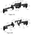
Figure 19 is a rear view of the securing means of the quick hitch ofFigures 9 to 12 with an actuator; -
Figure 20 is a rear view of the securing means ofFigure 19 without an actuator; -
Figure 21 is a rear view of the first over-centre mechanism of the quick hitch ofFigures 1 to 4 in an unlocked position; -
Figure 22 is a rear view of the first over-centre mechanism of the quick hitch ofFigures 1 to 4 in a locked position; -
Figure 23 is a front view of the first over-centre mechanism of the quick hitch ofFigures 9 to 12 in an unlocked position; and -
Figure 24 is a front view of the first over-centre mechanism of the quick hitch ofFigures 9 to 12 in a locked position. - Referring now to
Figures 1 to 8 ,17 ,18 ,21 and 22 , there is shown aquick hitch 2 according to a first embodiment of the invention. -
Figures 1 to 4 and21 show thequick hitch 2 in an unlocked position andFigures 5 to 8 ,17 ,18 and22 show thequick hitch 2 in a locked position. - The
quick hitch 2 has a body 4, mounting means 6a, 6b, 6c for mounting thequick hitch 2 on a machine and securing means 8 for securing an implement to thequick hitch 2. - The
quick hitch 2 also includes afirst pin 49a, second pin 49b and pivots 138, 140, 142, 144, 146. Each of thefirst pin 49a, second pin 49b and pivot 138 which has an axis G, pivot 140 which has an axis D, pivot 142 which has an axis C, pivot 144 which has an axis D', pivot 146 which has an axis G' are mounted on a chassis of thequick hitch 2. - The body 4 has
side walls base 14, anupper surface 16, afront wall 30 and arear wall 32. - The
base 14 has a pair ofapertures - The
upper surface 16 has anopening 20 and aplate 22. Theplate 22 has anopening 24 that corresponds to theopening 20 in theupper surface 16. Theplate 22 has brushes (not shown) within theopening 24. - The
front wall 30 is generally U-shaped. - The
rear wall 32 includes a pair ofaccess doors rear wall 32 and havelugs 7a, 7b, 7c, withapertures 9a, 9b, 9c for receiving supporting pins (not shown). Therear wall 32 also includes a pair of upwardly extendingarms arms removable plates - The
side walls base 14,upper surface 16,front wall 30 andrear wall 32 of the body provide an enclosure or casing for the securing means 8. - The securing means 8 includes a first
over-centre mechanism 36a and afirst locking member 38a. The firstover-centre mechanism 36a includes afirst link 40a and a firstpivotable member 42a. - The
first link 40a has afirst end 50a and asecond end 50b. Thefirst end 50a has apivot 148 which has an axis F. As shown inFigures 17 and 18 , thefirst link 40a is a resilient link and has a hollowcylindrical body 166, apiston member 168 and aspring 170. - The first
pivotable member 42a includes afirst arm 52, asecond arm 54 and athird arm 55. Thefirst arm 52 has apivot 150 which has an axis E. - The
first locking member 38a includes afirst projection 48a. - The securing means 8 includes a second
over-centre mechanism 36b and asecond locking member 38b. The secondover-centre mechanism 36b includes a secondfirst link 40b and a second first pivotable member 42b. - The second
first link 40b has afirst end 62a and a second end 62b. Thefirst end 62a has apivot 156 which has an axis F'. Similarly to thefirst link 40a, the secondfirst link 40b is a reslient link and has a hollowcylindrical body 172, apiston member 174 and a spring (not shown). - The second first pivotable member 42b includes a first arm 64, a
second arm 66 and athird arm 67. The first arm 64 has apivot 158 which has an axis E'. - The
second locking member 38b includes asecond projection 48b. - The securing means 8 further includes a
second link 44a and a second second link 44b. - The
second link 44a has a first end 56a and a second end 56b. The first end 56a has apivot 152 which has an axis A. The second end 56b has apivot 154 which has an axis B. - The second second link 44b has a
first end 68a and a second end 68b. Thefirst end 68a has a pivot 160 which has an axis A'. The second end 68b has apivot 162 which has an axis B'. - The securing means 8 further includes a second pivotable means 46. The second
pivotable member 46 has afirst end 58a, asecond end 58b and aplate 69. - The
plate 69 has a first end 65a and asecond end 65b. Theplate 69 also has three holes 164a, 164b, 164c. Hole 164a is located adjacent to the first end 65a of theplate 69, hole 164c is located adjacent to thesecond end 65b of theplate 69 and hole 164b is located between hole 164a and 164c along the length of theplate 69. - Assembly of the securing means 8 of the
quick hitch 2 of the first embodiment will now be described. - The first
over-centre mechanism 36a is assembled as follows. - The first
pivotable member 42a is pivotably mounted atpivot 140 such that the firstpivotable member 42a is able to pivot relative to the chassis of thequick hitch 2 about axis D. Thesecond end 50b of thefirst link 40a is pivotably mounted to thefirst arm 52 of the firstpivotable member 42a such that thefirst link 40a and the firstpivotable member 42a are able to pivot relative to each other about axis E. Thefirst end 50a of thefirst link 40a is pivotably mounted to thefirst locking member 38a such that thefirst link 40a and thefirst locking member 38a are able to pivot relative to each other about axis F. Thefirst locking member 38a is pivotably mounted at pivot 138 such that thefirst locking member 38a is able to pivot relative to the chassis of thequick hitch 2 about axis G. - The second
over-centre mechanism 36b is assembled as follows. - The second first pivotable member 42b is pivotably mounted at pivot 144 such that the second first pivotable member 42b is able to pivot relative to the chassis of the quick hitch about axis D'. The second end 62b of the second
first link 40b is pivotably mounted to the first arm 64 of the second first pivotable member 42b atpivot 158 such that the secondfirst link 40b and the second first pivobtable member 42b can pivot relative to each other about axis E'. Thefirst end end 62a of the secondfirst link 40b is pivotably mounted to thesecond locking member 38b atpivot 156 such that the secondfirst link 40b and thesecond locking member 38b can pivot relative to each other about axis F'. Thesecond locking member 38b is pivotably mounted at pivot 146 such that thesecond locking member 38b is able to pivot relative to the chassis of thequick hitch 2 about axis G'. - The
second end 58b of the secondpivotable member 46 and central hole 164b ofplate 69 are mounted on pivot 142 such that the secondpivotable member 46 and theplate 69 can rotate about axis C. - The first
over-centre mechanism 36a is linked to the secondpivotable member 46 and theplate 69 bysecond link 44a. Thethird arm 55 of the firstpivotable member 42a is pivotally mounted to the first end 56a of thesecond link 44a such that the firstpivotable member 42a and thesecond link 44a can pivot relative to each other about axis A. The second end 56b ofsecond link 44a is mounted on hole 164a at the first end 65a of theplate 69 atpivot 154 such that the second end 56b of thesecond link 44a can pivot about axis C. - The second
over-centre mechanism 36b is linked to the secondpivotable member 46 by second second link 44b. Thethird arm 67 of the second first pivotable member 42b is pivotally mounted to thefirst end 68a of the second second link 44b such that the second first pivotable member 42b and the second second link 44b can pivot relativ to each other about axis A'. The second end 68b of the second second link 44b is mounted on hole 164c at thesecond end 65b of theplate 69 atpivot 162 such that the second second link 44b can pivot about axis C. - The body 4 is partially constructed by assembling the
front wall 30, theside walls base 14 and theupper surface 16. - The securing means 8 is placed within the partially constructed body 4 such that the
first end 68a of the secondpivotable member 46 extends through theopening 20 in theupper surface 16, thefirst projection 48a of thefirst locking member 38a is positioned adjacent toaperture 28a in thebase 14 and thesecond projection 48b of thesecond locking member 38b is positioned adjacent toaperture 28b in thebase 14. - The
rear wall 30 is then mounted to theside walls base 14 and theupper surface 16 to complete the body 4. -
Plate 22 is mounted on theupper surface 16 of the body 4 usingfasteners 60 such that theopening 24 of theplate 22 corresponds to theopening 20 of theupper surface 16 and thefirst end 68a of the secondpivotable member 46 extends through opening 20 in theupper surface 16, the brushes (not shown) andopening 24 in theplate 22. -
Removable plate 26a is mounted onupper arm 18a using fasteners 27. In the same way,removable plate 26b is mounted onupper arm 18b using fasteners 27. - Use of the
quick hitch 2 to mount an implement, for example ashovel 180, as shown inFigures 3, 4 ,7 and 8 on a machine (not shown) will now be described. - The
quick hitch 2 is secured on the machine (not shown) with therear wall 32 of thequick hitch 2 facing the front of the machine (not shown). The mounting means 6a, 6c, 6c are secured on complementary mounting means (not shown) on the machine (not shown) by pins (not shown). - The
shovel 180 has abase 182,side walls 184a, 184b and arear wall 186. Therear wall 186 has alower lip 188, anupper lip 190 and anouter surface 192. Theupper lip 190 has alower surface 189. - The machine with the
quick hitch 2 in the unlocked position (as shown inFigures 1 to 4 ) and theshovel 180 are brought into close proximity such that thefront wall 30 of the quick hitch is adjacent to theouter surface 192 of therear wall 186 of theshovel 180. Theupper arms upper lip 190 such that theremovable plates lower surface 189 of theupper lip 190. Thebase 14 of the quick hitch is lined up with thelower lip 188 such that theapertures lower lip 188. - To lock the
shovel 180 on thequick hitch 2, thefirst end 58a of the secondpivotable member 46, which acts as a manual actuator or handle, is moved from the position shown inFigures 1 and 2 to the position shown inFigures 5 and 6 . Thefirst end 58a advantageously provides a single lever or handle for operating i.e. engaging and disengaging the quick hitch mechanism. - This causes the
second end 58b of the secondpivotable member 46, the second end 56b of thesecond link 44a and the second end 68b of the second second link 44b to be pivoted anticlockwise about axis C. - The pivoting movement of the second end 56b of the
second link 44a about pivot C causes the first end 56a of thesecond link 44a and thethird arm 55 of the firstpivotable member 42a to pivot clockwise relative to axis A, thesecond arm 54 of the firstpivotable member 42a to pivot clockwise relative to axis D and thefirst arm 52 of the firstpivotable member 42a to pivot clockwise relative to axis E. - The distance travelled by the
second arm 54 of the firstpivotable member 42a is limited bypin 49a against which thesecond arm 54 abuts when the securing means 8 is in the locked position. - The pivoting movement of the first
pivotable member 42a causes thesecond end 50b of thefirst link 40a to pivot anticlockwise relative to axis E and thefirst end 50a of thefirst link 40a to pivot anticlockwise relative to axis F. - The pivoting movement of the
first link 40a causes thefirst locking member 38a to pivot anticlockwise relative to axis F which causes thefirst projection 48a to move downward and to extend throughaperture 28a in thebase 14. - The
first projection 48a engages thelower lip 188 of theshovel 180 to lock theshovel 180 to thequick hitch 2. - When the securing means 8 is in the locked position, upward movement of the
first projection 48a is restricted by theresilient link 40a. - The pivoting movement of the second end 68b of the second second link 44b about pivot C causes the
first end 68a of the second second link 44b and thethird arm 67 of the second first pivotable member 42b to pivot anticlockwise relative to axis A', thesecond arm 66 of the second first pivotable member 42b to pivot anticlockwise relative to axis D' and the first arm 64 of the second first pivotable member 42b to pivot anticlockwise relative to axis E'. - The distance travelled by the
second arm 66 of the second first pivotable member 42b is limited by pin 49b against which it abuts. - The pivoting movement of the second first pivotable member 42b causes the second end 62b of the second
first link 40b to pivot anticlockwise relative to axis E' and thefirst end 62a of the secondfirst link 40b to pivot clockwise relative to axis F'. - The pivoting movement of the second
first link 40b causes thesecond locking member 38b to pivot clockwise relative to axis F' which causes thesecond projection 48b to move downward and to extend throughaperture 28b in thebase 14. - The
second projection 48b engages thelower lip 188 of theshovel 180 to lock theshovel 180 to thequick hitch 2. - When the securing means 8 is in the locked position, upward movement of the
second projection 48b is restricted by theresilient link 40b. - When the
quick hitch 2 is secured to the shovel 180 (as shown inFigure 21 ) axis E of the firstover-centre mechanism 36a lies on a first side of a straight line drawn between axes D and F and when the quick hitch is not secured to the shovel (as shown inFigure 22 ) axis E lies on a second side of a straight line drawn between axes D and F. In a similar way (not shown in the Figures) axis E' of the secondover-centre mechanism 36b lies on a first side of a straight line drawn between axes D' and F' when thequick hitch 2 is secured to theshovel 180 and when thequick hitch 2 is not secured to theshovel 180, axis E' lies on a second side of a straight line drawn between axes D' and F'. - In this way the first and
second projections pivotable member 46 when they are in the locked position. - The inclusion of a resilient, or spring-loaded,
first link 40a on one side of the securing means and a secondfirst link 40b on a second side of the securing means 8 ensures positive engagement of the first andsecond projections second projections lower lip 188 of theshovel 180. - The inclusion of the solid piston or
plunger 168 in a hollowcylindrical body 166 having aspring 170 limits the upward movement of the first andsecond projections pivotable member 46 and securing means 8 are in the locked position. This ensures attachment engagement at all times when the secondpivotable member 46 and securing means 8 are in the locked position. - The position of the second pivotable means 46 through the
opening 20 in theupper surface 16 and theopening 24 in theplate 22 when thequick hitch 2 is in the unlocked position compared to the position of the second pivotable means 46 through theopening 20 in theupper surface 16 and theopening 24 in theplate 22 when thequick hitch 2 is in the locked position indicates to an operator whether or not theshovel 180 is secured on thequick hitch 2. - The provision of the body 4 to enclose the securing means prevents damage being caused to the securing means 8 by dirt and debris. The provision of brushes (not shown) within the
opening 24 of the plate further prevents the ingress of dirt and debris into the body 4 of thequick hitch 2. - The provision of
removable plates arm portions lower surface 189 of theupper lip 190 of theshovel 180 increase the lifecycle of the quick hitch as theplates quick hitch 2 when worn and replaced with new, unworn, plates. - Referring now to
Figures 9 to 16 ,9 ,20 ,23 and 24 , there is shown aquick hitch 202 according to a second embodiment of the invention. -
Figures 9 to 12 and23 show thequick hitch 202 in an unlocked position andFigures 13 to 16 and24 show thequick hitch 202 in a locked position. - The
quick hitch 202 has a body 4, mounting means 6a, 6b, 6c for mounting thequick hitch 202 on a machine and securing means 208 for securing an implement to thequick hitch 2. - The
quick hitch 202 also includes afirst pin 49a, second pin 49b, athird pin 249c and pivots 138, 140, 142, 144, 146. Each of thefirst pin 49a, second pin 49b and pivot 138 which has an axis G", pivot 140 which has an axis D", pivot 142 which has an axis C", pivot 144 which has an axis D"', pivot 146 which has an axis G'" are mounted on a chassis of thequick hitch 202. - The body 4 has
side walls base 14, anupper surface 16, afront wall 30 and arear wall 32. - The
base 14 has a pair ofapertures - The
upper surface 16 has anopening 20 and aplate 22. Theplate 22 has anopening 24 that corresponds to theopening 20 in theupper surface 16. Theplate 22 has brushes (not shown) within theopening 24. - The
front wall 30 is generally U-shaped. - The
rear wall 32 includes a pair ofaccess doors rear wall 32 and havelugs 7a, 7b, 7c, withapertures 9a, 9b, 9c for receiving supporting pins (not shown). Therear wall 32 also includes a pair of upwardly extendingarms arms removable plates - The
side walls base 14,upper surface 16,front wall 30 andrear wall 32 of the body provide an enclosure or casing for the securing means 208. - The securing means 208 includes a first
over-centre mechanism 236a and afirst locking member 238a. The firstover-centre mechanism 236a includes afirst link 240a and a firstpivotable member 242a. - The
first link 240a has afirst end 250a and asecond end 250b. Thefirst end 250a has apivot 348 which has an axis F". Thefirst link 240a is a resilient link and (as shown inFigures 17 and 18 in relation thefirst link 40a of the first embodiment) has a hollowcylindrical body 166, apiston member 168 and aspring 170. - As shown in
Figure 20 , the firstpivotable member 242a includes afirst arm 252, asecond arm 254, athird arm 255 and aleg 253. Thefirst arm 252 has a pivot 350 which has an axis E". Theleg 253 has ahook portion 253a. - The
first locking member 238a includes afirst projection 248a. - The securing means 208 includes a second
over-centre mechanism 236b and asecond locking member 238b. The secondover-centre mechanism 236b includes a second first link 240b and a second first pivotable member 242b. - The second first link 240b has a
first end 262a and a second end 262b. Thefirst end 262a has apivot 356 which has an axis F"'. Similarly to thefirst link 240a, the second first link 240b is a resilient link and has a hollowcylindrical body 372, a piston member 374 and a spring (not shown). - The second first pivotable member 242b includes a
first arm 264, asecond arm 266 and athird arm 267. Thefirst arm 264 has apivot 358 which has an axis E"'. - The
second locking member 238b includes asecond projection 248b. - The securing means 208 further includes an
actuator 360. As shown more clearly inFigure 19 , theactuator 360 has ascrew actuator 362 and amotor 364. Thescrew actuator 362 has afirst end 366a and a second end 366b. - Assembly of the securing means 208 of the
quick hitch 202 of the second embodiment will now be described. - The first
over-centre mechanism 236a is assembled as follows. - The first
pivotable member 242a is pivotably mounted atpivot 340 such that the firstpivotable member 242a is able to pivot relative to the chassis of thequick hitch 202 about axis D". Thesecond end 250b of thefirst link 240a is pivotably mounted to thefirst arm 252 of the firstpivotable member 242a such that thefirst link 240a and the firstpivotable member 242a are able to pivot relative to each other about axis E". Thefirst end 250a of thefirst link 240a is pivotably mounted to thefirst locking member 238a such that thefirst link 240a and thefirst locking member 238a are able to pivot relative to each other about axis F". Thefirst locking member 238a is pivotably mounted at pivot 338 such that thefirst locking member 238a is able to pivot relative to the chassis of thequick hitch 202 about axis G". - The second
over-centre mechanism 236b is assembled as follows. - The second first pivotable member 242b is pivotably mounted at pivot 344 such that the second first pivotable member 242b is able to pivot relative to the chassis of the quick hitch about axis D"'. The second end 262b of the second first link 240b is pivotably mounted to the
first arm 264 of the second first pivotable member 242b atpivot 358 such that the second first link 240b and the second first pivotable member 242b can pivot relative to each other about axis E"'. Thefirst end 262a of the second first link 240b is pivotably mounted to thesecond locking member 238b atpivot 356 such that the second first link 240b and thesecond locking member 238b can pivot relative to each other about axis F"'. Thesecond locking member 238b is pivotably mounted at pivot 346 such that thesecond locking member 238b is able to pivot relative to the chassis of thequick hitch 202 about axis G"'. - The first
over-centre mechanism 236a is linked to the secondover-centre mechanism 236b by theactuator 360. Thesecond arm 255 of the firstpivotable member 242a is mounted on thefirst end 366a of thescrew actuator 360. Thethird arm 267 of the second first pivotable member 242b is mounted on the second end 366b of thescrew actuator 362. - The body 4 is partially constructed by assembling the
front wall 30, theside walls base 14 and theupper surface 16. - The securing means 208 is placed within the partially constructed body 4 such that the
leg 253 of the firstpivotable member 242a extends through theopening 20 in theupper surface 16, thefirst projection 248a of thefirst locking member 238a is positioned adjacent toaperture 28a in thebase 14 and thesecond projection 248b of thesecond locking member 238b is positioned adjacent toaperture 28b in thebase 14. - The
rear wall 30 is then mounted to theside walls base 14 and theupper surface 16 to complete the body 4. -
Plate 22 is mounted on theupper surface 16 of the body 4 usingfasteners 60 such that theopening 24 of theplate 22 corresponds to theopening 20 of theupper surface 16 and theleg 253 of the firstpivotable member 242a extends through opening 20 in theupper surface 16, the brushes (not shown) andopening 24 in theplate 22. -
Removable plate 26a is mounted onupper arm 18a using fasteners 27. In the same way,removable plate 26b is mounted onupper arm 18b using fasteners 27. - Use of the
quick hitch 202 to mount an implement, for example ashovel 180, as shown inFigures 11, 12 ,15 and 16 on a machine (not shown) will now be described. - The
quick hitch 2 is secured on the machine (not shown) with therear wall 32 of thequick hitch 2 facing the front of the machine (not shown). The mounting means 6a, 6c, 6c are secured on complementary mounting means (not shown) on the machine (not shown) by pins (not shown). - The
shovel 180 has abase 182,side walls 184a, 184b and arear wall 186. Therear wall 186 has alower lip 188, anupper lip 190 and anouter surface 192. Theupper lip 190 has alower surface 189. - The machine with the
quick hitch 202 in the unlocked position (as shown inFigures 9 to 12 ) and theshovel 180 are brought into close proximity such that thefront wall 30 of thequick hitch 202 is adjacent to theouter surface 192 of therear wall 186 of theshovel 180. Theupper arms upper lip 190 such that theremovable plates lower surface 189 of theupper lip 190. Thebase 14 of the quick hitch is lined up with thelower lip 188 such that theapertures lower lip 188. - To lock the
shovel 180 on thequick hitch 202, theactuator 360 is activated to move theleg 253 of the firstpivotable member 242a from the position shown inFigures 9 and 10 to the position shown inFigures 13 and 14 . - This causes the first
pivotable member 242a to rotate in a clockwise direction such that thehook portion 253a of theleg 253 abuts thepin 249c, thesecond arm 266 abutspin 49a and theactuator 360 is moved in an upward direction. - The rotation of the first
pivotable member 242a causes thefirst link 240a to rotate in an anticlockwise direction. - The pivoting movement of the
first link 240a causes thefirst locking member 238a to pivot anticlockwise relative to axis F" which causes thefirst projection 248a to move downward and to extend throughaperture 28a in thebase 14. - The
first projection 248a engages thelower lip 188 of theshovel 180 to lock theshovel 180 to thequick hitch 202. - When the securing means 208 is in the locked position, upward movement of the
first projection 248a is restricted by theresilient link 240a. - The upward movement of the
actuator 360 causes thethird arm 267 of the second first pivotable member 242b to pivot anticlockwise relative to axis A"', thesecond arm 266 of the second first pivotable member 242b to pivot anticlockwise relative to axis D'" and thefirst arm 264 of the second first pivotable member 242b to pivot anticlockwise relative to axis E"'. - The distance travelled by the
second arm 266 of the second first pivotable member 242b is limited by pin 49b against which thesecond arm 266 abuts when the securing means 208 in the locked position. - The pivoting movement of the second first pivotable member 242b causes the second end 262b of the second first link 240b to pivot anticlockwise relative to axis E'" and the
first end 262a of the second first link 240b to pivot clockwise relative to axis F"'. - The pivoting movement of the second first link 240b causes the
second locking member 238b to pivot clockwise relative to axis F'" which causes thesecond projection 248b to move downward and to extend throughaperture 28b in thebase 14. - The
second projection 248b engages thelower lip 188 of theshovel 180 to lock theshovel 180 to thequick hitch 2. - When the securing means 208 is in the locked position, upward movement of the
second projection 248b is restricted by the resilient link 240b. - When the
quick hitch 202 is secured to the shovel 180 (as shown inFigure 23 ) axis E" of the firstover-centre mechanism 236a lies on a first side of a straight line drawn between axes D" and F" and when the quick hitch is not secured to the shovel (as shown inFigure 24 ) axis E" lies on a second side of a straight line drawn between axes D" and F". In a similar way (not shown in the Figures) axis E'" of the secondover-centre mechanism 236b lies on a first side of a straight line drawn between axes D'" and F'" when thequick hitch 202 is secured to theshovel 180 and when thequick hitch 202 is not secured to theshovel 180, axis E'" lies on a second side of a straight line drawn between axes D'" and F"'. - In this way the first and
second projections actuator 360 when they are in the locked position. - The inclusion of a resilient, or spring-loaded,
first link 240a on one side of the securing means 208 and a second first link 240b on a second side of the securing means 208 ensures positive engagement of the first andsecond projections second projections lower lip 188 of theshovel 180. - The inclusion of the solid piston or plunger 368 in a hollow cylindrical body 366 having a spring 370 limits the upward movement of the first and
second projections - The position of the
leg 253 of the first pivotable means 242a through theopening 20 in theupper surface 16 and theopening 24 in theplate 22 when thequick hitch 2 is in the unlocked position compared to the position of theleg 253 of the first pivotable means 242a within the body 4 of the quick hitch (i.e. not visible to an operator) indicates or provides a signal to an operator whether or not theshovel 180 is secured on thequick hitch 202. - The provision of the body 4 to enclose the securing means prevents damage being caused to the securing means 208 by dirt and debris. The provision of brushes (not shown) within the
opening 24 of the plate further prevents the ingress of dirt and debris into the body 4 of thequick hitch 202. - The provision of
removable plates arm portions lower surface 189 of theupper lip 190 of theshovel 180 increase the lifecycle of thequick hitch 202 as theplates quick hitch 2 when worn and replaced with new, unworn, plates. - In the embodiments described above the
quick hitches wear plates over-centre mechanism resilient link - In the embodiments described above, the
plate 22 included brushes (not shown) for preventing the ingress of dirt and debris into the body 4 of thequick hitch openings
Claims (14)
- A quick hitch for mounting an implement on a machine, the quick hitch including at least one mounting means for connection to a machine and a securing means for securing the quick hitch to an implement, the securing means including an over-centre mechanism and a locking member, the over-centre mechanism including a first link and a first pivotable member, wherein the first pivotable member is pivotal at a first axis D relative to a chassis of the quick hitch, a first end of the first link is pivotal at a second axis E relative to a first arm of the first pivotable member, and a second end of the first link is pivotal at a third axis F relative to the locking member, such that with the securing means in a first position, in which the quick hitch is secured to an implement, axis E lies on a first side of a straight line drawn between axes D and F and with the securing means in a second position, in which the quick hitch is not secured to an implement, axis E lies on a second side of a straight line drawn between axes D and F, for example wherein the locking member includes a projection for engaging an implement when the securing means is in a first position and/or wherein the quick hitch includes a first pin and the first pivotable member includes a second arm, such that with the securing means in the first position, the second arm is in abutment with the first pin and with the securing means in the second position, the second arm is spaced from the first pin.
- A quick hitch according to claim 1, wherein the quick hitch further includes a second pivotable member and the securing means includes a second link, wherein a first end of the second pivotable member is pivotal at a fourth axis A relative to the chassis of the quick hitch, a first end of the second link is pivotal at a fifth axis B relative to the second pivotable member, and a second end of the second link is pivotal at a sixth axis C relative to the first pivotable member, such that with the securing means in the first position, axis B lies on a first side of a straight line drawn between axes A and C and with the securing means in the second position, axis B lies on a second side of a straight line drawn between axes A and C.
- A quick hitch according to claim 2, wherein a second end of the second pivotable member is an actuator for moving the securing means from the first position to the second position, for example wherein the actuator is manual, for example wherein the actuator comprises a single handle.
- A quick hitch according to claim 3, wherein the second end of the second pivotable member includes a signal means, the signal means having a first position for signalling that the quick hitch is secured to an implement when the securing means is in the first position and a second position for signalling that the quick hitch is not secured to an implement when the securing means is in the second position.
- A quick hitch according to any of claims 2 to 4, wherein the first link and/or the second link is a resilient link.
- A quick hitch according to claim 1, wherein the securing means includes an actuator that is operably connected to the first pivotable member such that actuation of the actuator causes the securing means to move from the first position to the second position, for example wherein the actuator is a screw actuator and/or wherein the actuator is an electric actuator.
- A quick hitch according to claim 6, wherein the quick hitch includes a second pin and the first pivotable member includes a leg, such that with the securing means in the first position, the leg is in abutment with the second pin and with the securing means in the second position, the leg is spaced from the second pin, for example wherein the leg includes a signal means, the signal means having a first position for signalling that the quick hitch is secured to an implement when the securing means is in the first position and a second position for signalling that the quick hitch is not secured to an implement when the securing means is in the second position and/or wherein the first link is a resilient link.
- A quick hitch according to any of claims 1 to 7, wherein the over-centre mechanism of the securing means is a first over-centre mechanism, the locking member is a first locking member, the first link is a first first link, the first pivotable member is a first first pivotable member, the first axis D is the first first axis, the second axis E is the first second axis, the first arm of the first first pivotable member is the first first arm and the third axis F is the first third axis, the securing means further including a second over-centre mechanism and a second locking member, the second over-centre mechanism including a second first link and a second first pivotable member, wherein the second first pivotable member is pivotal at a second first axis D' relative to a chassis of the quick hitch, a first end of the second first link is pivotal at a second second axis E' relative to a second first arm of the second first pivotable member, and a second end of the second first link is pivotal at a second third axis F' relative to the second locking member, such that with the securing means in a first position, in which the quick hitch is secured to an implement, axis E' lies on a first side of a straight line drawn between axes D' and F' and with the securing means in a second position, in which the quick hitch is not secured to an implement, axis E' lies on a second side of a straight line drawn between axes D' and F' and/or wherein the quick hitch further includes an enclosure and/or wherein the quick hitch further includes at least one removable plate for engagement with a surface of an implement.
- A quick hitch for mounting an implement on a machine, the quick hitch including at least one mounting means for connection to a machine and a securing means for securing the quick hitch to an implement, the securing means including a locking member and a second pivotable member, wherein the locking member and the second pivotable member are connected by a resilient link; the securing means having a first position in which the quick hitch is secured to an implement and a second position in which the quick hitch is not secured to an implement, wherein when the securing means is in the first position, the resilient link allows movement of the securing means to a third position which is between the first position and the second position.
- A quick hitch according to claim 9, wherein the locking member has a first position when the securing means is in the first position and a second position when the securing means is in the third position and the first and second positions of the locking member are separated by an axial distance, for example wherein the axial distance is less than 20 millimetres and/or wherein the axial distance is less than 16 millimetres and/or wherein the axial distance is greater than 10 millimetres and/or wherein the axial distance is greater than 12 millimetres.
- A quick hitch according to claim 9 or claim 10, wherein the securing means further includes a first link, a first pivotable member and a second link, wherein the first pivotable member is pivotal at a first axis D relative to a chassis of the quick hitch, a first end of the first link is pivotal at a second axis E relative to a first arm of the first pivotable member, a second end of the first link is pivotal at a third axis F relative to the locking member, a first end of the second pivotable member is pivotal at a fourth axis A relative to the chassis of the quick hitch, a first end of the second link is pivotal at a fifth axis B relative to the second pivotable member, and a second end of the second link is pivotal at a sixth axis C relative to the first pivotable member, for example wherein one or more of the first link, the first pivotable member, the second link and/or the second pivotable member may be the resilient link and/or wherein the first link is the resilient link and/or wherein the quick hitch includes a first pin and the first pivotable member includes a second arm, such that with the securing means in the first position, the second arm is in abutment with the first pin and with the securing means in the second position, the second arm is spaced from the first pin and/or wherein the second pivotable member includes a signal means, the signal means having a first position for signalling that the quick hitch is secured to an implement when the securing means is in the first position and a second position for signalling that the quick hitch is not secured to an implement when the securing means is in the second position and/or wherein the locking member is pivotally connected to the resilient link and/or wherein the second pivotable member is a manual actuator, for example wherein the manual actuator comprises a single handle.
- A quick hitch according to any of claims 9 to 11, wherein the securing means further includes an electric actuator.
- A quick hitch according to claim 12, wherein the electric actuator is operably connected to the second pivotable member such that actuation of the actuator causes the securing means to move from the first position to the second position and/or wherein the quick hitch includes a second pin and the second pivotable member includes a leg, such that with the securing means in the first position, the leg is in abutment with the second pin and with the securing means in the second position, the leg is spaced from the second pin, for example wherein the leg includes a signal means, the signal means having a first position for signalling that the quick hitch is secured to an implement when the securing means is in the first position and a second position for signalling that the quick hitch is not secured to an implement when the securing means is in the second position.
- A quick hitch according to any of claims 9 to 13, wherein the locking member is the first locking member, the second pivotable member is the first second pivotable member, and the resilient link is the first resilient link, the securing means further including a second locking member and a second second pivotable member, wherein the second locking member and the second second pivotable member are connected by a second resilient link, wherein when the securing means is in the first position, the second resilient link allows movement of the securing means to a third position which is between the first position and the second position and/or wherein the quick hitch further includes an enclosure and/or wherein the quick hitch further includes at least one removable plate for engagement with a surface of an implement.
Applications Claiming Priority (1)
| Application Number | Priority Date | Filing Date | Title |
|---|---|---|---|
| GB1518253.8A GB2543332B (en) | 2015-10-15 | 2015-10-15 | Quick hitch |
Publications (3)
| Publication Number | Publication Date |
|---|---|
| EP3165682A2 true EP3165682A2 (en) | 2017-05-10 |
| EP3165682A3 EP3165682A3 (en) | 2017-07-26 |
| EP3165682B1 EP3165682B1 (en) | 2022-12-07 |
Family
ID=55131083
Family Applications (1)
| Application Number | Title | Priority Date | Filing Date |
|---|---|---|---|
| EP16191790.1A Active EP3165682B1 (en) | 2015-10-15 | 2016-09-30 | Quick hitch |
Country Status (7)
| Country | Link |
|---|---|
| US (1) | US10132054B2 (en) |
| EP (1) | EP3165682B1 (en) |
| JP (2) | JP6856348B2 (en) |
| KR (1) | KR20170044601A (en) |
| CN (1) | CN106917426A (en) |
| BR (1) | BR102016023870B1 (en) |
| GB (2) | GB2543332B (en) |
Cited By (1)
| Publication number | Priority date | Publication date | Assignee | Title |
|---|---|---|---|---|
| SE1950683A1 (en) * | 2019-06-10 | 2020-12-11 | Vaederstad Holding Ab | Apparatus and method for attaching a row unit and agricultural implements comprising such an apparatus |
Families Citing this family (2)
| Publication number | Priority date | Publication date | Assignee | Title |
|---|---|---|---|---|
| US10597844B2 (en) * | 2016-08-05 | 2020-03-24 | Diversified Products, LLC | Single cylinder hydraulic coupler |
| US20200283977A1 (en) * | 2019-03-04 | 2020-09-10 | Buyers Products Company | Snow plow mounting assembly |
Family Cites Families (27)
| Publication number | Priority date | Publication date | Assignee | Title |
|---|---|---|---|---|
| CA814808A (en) * | 1969-06-10 | S. Antolini Henry | Earth moving equipment | |
| US3531140A (en) * | 1968-01-26 | 1970-09-29 | Int Harvester Co | Tractor quick hitch attachment |
| US4119225A (en) * | 1977-04-18 | 1978-10-10 | Owatonna Manufacturing Company, Inc. | Mounting means for attaching an implement to a vehicle |
| JP2856503B2 (en) * | 1990-05-11 | 1999-02-10 | 日本電気株式会社 | Communication base condition identification method |
| JP2510778Y2 (en) * | 1990-05-31 | 1996-09-18 | 東洋運搬機株式会社 | Attachment mounting device for earthwork vehicle work |
| US5419673A (en) * | 1993-03-11 | 1995-05-30 | Memo Industrial Planning, Inc. | Quick disconnect apparatus for tractor front loader |
| US5456030A (en) * | 1993-06-21 | 1995-10-10 | Barone, Inc. | Quick coupler for heavy equipment implements |
| DE9314409U1 (en) * | 1993-09-23 | 1994-03-10 | Lehnhoff Hartstahl Gmbh & Co | Quick change device |
| JPH07331704A (en) * | 1994-06-14 | 1995-12-19 | Shin Caterpillar Mitsubishi Ltd | Operation system lock device |
| US5692855A (en) * | 1994-06-21 | 1997-12-02 | Farmers' Factory Co. | Automatic quick-connect coupler for implements |
| US5769596A (en) * | 1994-09-06 | 1998-06-23 | Farmers' Factory Co. | Electrically actuated quick-connect coupler |
| US5685689A (en) * | 1996-01-03 | 1997-11-11 | Great Bend Manufacturing Co., Inc. | Quick attach system for front end loader |
| US5836734A (en) * | 1997-10-17 | 1998-11-17 | Deere & Company | Latching device with detent |
| US6170178B1 (en) * | 1998-05-28 | 2001-01-09 | M.J. Electric, Inc. | Powered quick attach snowplow |
| US6238130B1 (en) * | 1999-01-15 | 2001-05-29 | Case Corporation | Coupling device for a skid steer |
| US6332748B1 (en) * | 1999-11-09 | 2001-12-25 | Deere & Company | Rotating pawl tool latch |
| GB2359062B (en) * | 2000-02-11 | 2002-01-02 | Ronald Keith Miller | Universal coupler for bucket excavators |
| US6301811B1 (en) * | 2000-07-28 | 2001-10-16 | Gilmore Industries, Inc. | Coupler for a heavy-duty machine |
| CA2358339C (en) * | 2001-10-05 | 2010-06-15 | Peninsula Alloy Inc. | Wear plate assembly |
| IES20040192A2 (en) * | 2004-03-26 | 2005-10-19 | Patrick Mccormick | An excavator tool quick attachment device |
| US7513732B1 (en) * | 2007-01-31 | 2009-04-07 | Callens Albert C | Loader attachment system |
| US7984575B2 (en) * | 2007-07-05 | 2011-07-26 | Caterpillar Inc. | Quick coupler assembly |
| GB2451304B (en) * | 2007-12-31 | 2009-11-18 | Quick Switch | Quick Hitch |
| US7562718B1 (en) * | 2008-02-29 | 2009-07-21 | Buyers Products Company | Locking mechanism for mounting a plow to a vehicle |
| JP4772841B2 (en) * | 2008-09-10 | 2011-09-14 | 株式会社クボタ | Work implement mounting device for loader work machine |
| KR101093218B1 (en) * | 2009-08-12 | 2011-12-13 | 주식회사 에버다임 | Attachment coupler for heavy machinery |
| US20140096419A1 (en) * | 2012-10-08 | 2014-04-10 | Caterpillar Sarl | Work tool coupler linkage |
-
2015
- 2015-10-15 GB GB1518253.8A patent/GB2543332B/en active Active
- 2015-10-15 GB GB2109027.9A patent/GB2593396B/en active Active
-
2016
- 2016-09-30 EP EP16191790.1A patent/EP3165682B1/en active Active
- 2016-10-12 US US15/291,852 patent/US10132054B2/en active Active
- 2016-10-13 BR BR102016023870-6A patent/BR102016023870B1/en active IP Right Grant
- 2016-10-13 KR KR1020160133152A patent/KR20170044601A/en not_active Application Discontinuation
- 2016-10-14 CN CN201610898699.7A patent/CN106917426A/en active Pending
- 2016-10-17 JP JP2016203782A patent/JP6856348B2/en active Active
-
2021
- 2021-03-17 JP JP2021043892A patent/JP7160983B2/en active Active
Cited By (2)
| Publication number | Priority date | Publication date | Assignee | Title |
|---|---|---|---|---|
| SE1950683A1 (en) * | 2019-06-10 | 2020-12-11 | Vaederstad Holding Ab | Apparatus and method for attaching a row unit and agricultural implements comprising such an apparatus |
| SE544226C2 (en) * | 2019-06-10 | 2022-03-08 | Vaederstad Holding Ab | Device and method for attaching a row unit and agricultural implements comprising such a device |
Also Published As
| Publication number | Publication date |
|---|---|
| BR102016023870A2 (en) | 2017-11-21 |
| JP6856348B2 (en) | 2021-04-07 |
| EP3165682B1 (en) | 2022-12-07 |
| KR20170044601A (en) | 2017-04-25 |
| BR102016023870B1 (en) | 2022-09-06 |
| GB2543332B (en) | 2021-08-18 |
| GB2543332A (en) | 2017-04-19 |
| CN106917426A (en) | 2017-07-04 |
| GB2593396B (en) | 2021-12-29 |
| JP7160983B2 (en) | 2022-10-25 |
| GB201518253D0 (en) | 2015-12-02 |
| US10132054B2 (en) | 2018-11-20 |
| GB2593396A (en) | 2021-09-22 |
| US20170107685A1 (en) | 2017-04-20 |
| JP2017075525A (en) | 2017-04-20 |
| GB202109027D0 (en) | 2021-08-04 |
| EP3165682A3 (en) | 2017-07-26 |
| JP2021099028A (en) | 2021-07-01 |
Similar Documents
| Publication | Publication Date | Title |
|---|---|---|
| JP7160982B2 (en) | quick hitch | |
| JP7160983B2 (en) | quick hitch | |
| AU2017200709B2 (en) | Wear assembly | |
| US9481978B2 (en) | Thumb with detachable body | |
| GB2596256A (en) | Quick hitch | |
| EP3575495A1 (en) | Multiple interface tool for a construction machine | |
| JP2023050417A (en) | bucket | |
| CN112942458A (en) | Excavator and connecting mechanism for excavator | |
| NZ623750B2 (en) | Wear assembly |
Legal Events
| Date | Code | Title | Description |
|---|---|---|---|
| PUAI | Public reference made under article 153(3) epc to a published international application that has entered the european phase |
Free format text: ORIGINAL CODE: 0009012 |
|
| STAA | Information on the status of an ep patent application or granted ep patent |
Free format text: STATUS: THE APPLICATION HAS BEEN PUBLISHED |
|
| AK | Designated contracting states |
Kind code of ref document: A2 Designated state(s): AL AT BE BG CH CY CZ DE DK EE ES FI FR GB GR HR HU IE IS IT LI LT LU LV MC MK MT NL NO PL PT RO RS SE SI SK SM TR |
|
| AX | Request for extension of the european patent |
Extension state: BA ME |
|
| PUAL | Search report despatched |
Free format text: ORIGINAL CODE: 0009013 |
|
| AK | Designated contracting states |
Kind code of ref document: A3 Designated state(s): AL AT BE BG CH CY CZ DE DK EE ES FI FR GB GR HR HU IE IS IT LI LT LU LV MC MK MT NL NO PL PT RO RS SE SI SK SM TR |
|
| AX | Request for extension of the european patent |
Extension state: BA ME |
|
| RIC1 | Information provided on ipc code assigned before grant |
Ipc: E02F 9/26 20060101ALI20170620BHEP Ipc: E02F 3/36 20060101AFI20170620BHEP |
|
| STAA | Information on the status of an ep patent application or granted ep patent |
Free format text: STATUS: REQUEST FOR EXAMINATION WAS MADE |
|
| 17P | Request for examination filed |
Effective date: 20180123 |
|
| RBV | Designated contracting states (corrected) |
Designated state(s): AL AT BE BG CH CY CZ DE DK EE ES FI FR GB GR HR HU IE IS IT LI LT LU LV MC MK MT NL NO PL PT RO RS SE SI SK SM TR |
|
| GRAP | Despatch of communication of intention to grant a patent |
Free format text: ORIGINAL CODE: EPIDOSNIGR1 |
|
| STAA | Information on the status of an ep patent application or granted ep patent |
Free format text: STATUS: GRANT OF PATENT IS INTENDED |
|
| INTG | Intention to grant announced |
Effective date: 20210625 |
|
| GRAJ | Information related to disapproval of communication of intention to grant by the applicant or resumption of examination proceedings by the epo deleted |
Free format text: ORIGINAL CODE: EPIDOSDIGR1 |
|
| STAA | Information on the status of an ep patent application or granted ep patent |
Free format text: STATUS: REQUEST FOR EXAMINATION WAS MADE |
|
| STAA | Information on the status of an ep patent application or granted ep patent |
Free format text: STATUS: EXAMINATION IS IN PROGRESS |
|
| STAA | Information on the status of an ep patent application or granted ep patent |
Free format text: STATUS: EXAMINATION IS IN PROGRESS |
|
| INTC | Intention to grant announced (deleted) | ||
| 17Q | First examination report despatched |
Effective date: 20211201 |
|
| GRAP | Despatch of communication of intention to grant a patent |
Free format text: ORIGINAL CODE: EPIDOSNIGR1 |
|
| STAA | Information on the status of an ep patent application or granted ep patent |
Free format text: STATUS: GRANT OF PATENT IS INTENDED |
|
| INTG | Intention to grant announced |
Effective date: 20220801 |
|
| GRAS | Grant fee paid |
Free format text: ORIGINAL CODE: EPIDOSNIGR3 |
|
| GRAA | (expected) grant |
Free format text: ORIGINAL CODE: 0009210 |
|
| STAA | Information on the status of an ep patent application or granted ep patent |
Free format text: STATUS: THE PATENT HAS BEEN GRANTED |
|
| AK | Designated contracting states |
Kind code of ref document: B1 Designated state(s): AL AT BE BG CH CY CZ DE DK EE ES FI FR GB GR HR HU IE IS IT LI LT LU LV MC MK MT NL NO PL PT RO RS SE SI SK SM TR |
|
| REG | Reference to a national code |
Ref country code: GB Ref legal event code: FG4D |
|
| REG | Reference to a national code |
Ref country code: CH Ref legal event code: EP Ref country code: AT Ref legal event code: REF Ref document number: 1536368 Country of ref document: AT Kind code of ref document: T Effective date: 20221215 |
|
| REG | Reference to a national code |
Ref country code: DE Ref legal event code: R096 Ref document number: 602016076745 Country of ref document: DE |
|
| REG | Reference to a national code |
Ref country code: IE Ref legal event code: FG4D |
|
| REG | Reference to a national code |
Ref country code: LT Ref legal event code: MG9D |
|
| REG | Reference to a national code |
Ref country code: NL Ref legal event code: MP Effective date: 20221207 |
|
| PG25 | Lapsed in a contracting state [announced via postgrant information from national office to epo] |
Ref country code: SE Free format text: LAPSE BECAUSE OF FAILURE TO SUBMIT A TRANSLATION OF THE DESCRIPTION OR TO PAY THE FEE WITHIN THE PRESCRIBED TIME-LIMIT Effective date: 20221207 Ref country code: NO Free format text: LAPSE BECAUSE OF FAILURE TO SUBMIT A TRANSLATION OF THE DESCRIPTION OR TO PAY THE FEE WITHIN THE PRESCRIBED TIME-LIMIT Effective date: 20230307 Ref country code: LT Free format text: LAPSE BECAUSE OF FAILURE TO SUBMIT A TRANSLATION OF THE DESCRIPTION OR TO PAY THE FEE WITHIN THE PRESCRIBED TIME-LIMIT Effective date: 20221207 Ref country code: FI Free format text: LAPSE BECAUSE OF FAILURE TO SUBMIT A TRANSLATION OF THE DESCRIPTION OR TO PAY THE FEE WITHIN THE PRESCRIBED TIME-LIMIT Effective date: 20221207 Ref country code: ES Free format text: LAPSE BECAUSE OF FAILURE TO SUBMIT A TRANSLATION OF THE DESCRIPTION OR TO PAY THE FEE WITHIN THE PRESCRIBED TIME-LIMIT Effective date: 20221207 |
|
| REG | Reference to a national code |
Ref country code: AT Ref legal event code: MK05 Ref document number: 1536368 Country of ref document: AT Kind code of ref document: T Effective date: 20221207 |
|
| PG25 | Lapsed in a contracting state [announced via postgrant information from national office to epo] |
Ref country code: RS Free format text: LAPSE BECAUSE OF FAILURE TO SUBMIT A TRANSLATION OF THE DESCRIPTION OR TO PAY THE FEE WITHIN THE PRESCRIBED TIME-LIMIT Effective date: 20221207 Ref country code: PL Free format text: LAPSE BECAUSE OF FAILURE TO SUBMIT A TRANSLATION OF THE DESCRIPTION OR TO PAY THE FEE WITHIN THE PRESCRIBED TIME-LIMIT Effective date: 20221207 Ref country code: LV Free format text: LAPSE BECAUSE OF FAILURE TO SUBMIT A TRANSLATION OF THE DESCRIPTION OR TO PAY THE FEE WITHIN THE PRESCRIBED TIME-LIMIT Effective date: 20221207 Ref country code: HR Free format text: LAPSE BECAUSE OF FAILURE TO SUBMIT A TRANSLATION OF THE DESCRIPTION OR TO PAY THE FEE WITHIN THE PRESCRIBED TIME-LIMIT Effective date: 20221207 Ref country code: GR Free format text: LAPSE BECAUSE OF FAILURE TO SUBMIT A TRANSLATION OF THE DESCRIPTION OR TO PAY THE FEE WITHIN THE PRESCRIBED TIME-LIMIT Effective date: 20230308 |
|
| PG25 | Lapsed in a contracting state [announced via postgrant information from national office to epo] |
Ref country code: NL Free format text: LAPSE BECAUSE OF FAILURE TO SUBMIT A TRANSLATION OF THE DESCRIPTION OR TO PAY THE FEE WITHIN THE PRESCRIBED TIME-LIMIT Effective date: 20221207 |
|
| P01 | Opt-out of the competence of the unified patent court (upc) registered |
Effective date: 20230525 |
|
| PG25 | Lapsed in a contracting state [announced via postgrant information from national office to epo] |
Ref country code: SM Free format text: LAPSE BECAUSE OF FAILURE TO SUBMIT A TRANSLATION OF THE DESCRIPTION OR TO PAY THE FEE WITHIN THE PRESCRIBED TIME-LIMIT Effective date: 20221207 Ref country code: RO Free format text: LAPSE BECAUSE OF FAILURE TO SUBMIT A TRANSLATION OF THE DESCRIPTION OR TO PAY THE FEE WITHIN THE PRESCRIBED TIME-LIMIT Effective date: 20221207 Ref country code: PT Free format text: LAPSE BECAUSE OF FAILURE TO SUBMIT A TRANSLATION OF THE DESCRIPTION OR TO PAY THE FEE WITHIN THE PRESCRIBED TIME-LIMIT Effective date: 20230410 Ref country code: EE Free format text: LAPSE BECAUSE OF FAILURE TO SUBMIT A TRANSLATION OF THE DESCRIPTION OR TO PAY THE FEE WITHIN THE PRESCRIBED TIME-LIMIT Effective date: 20221207 Ref country code: CZ Free format text: LAPSE BECAUSE OF FAILURE TO SUBMIT A TRANSLATION OF THE DESCRIPTION OR TO PAY THE FEE WITHIN THE PRESCRIBED TIME-LIMIT Effective date: 20221207 Ref country code: AT Free format text: LAPSE BECAUSE OF FAILURE TO SUBMIT A TRANSLATION OF THE DESCRIPTION OR TO PAY THE FEE WITHIN THE PRESCRIBED TIME-LIMIT Effective date: 20221207 |
|
| PG25 | Lapsed in a contracting state [announced via postgrant information from national office to epo] |
Ref country code: SK Free format text: LAPSE BECAUSE OF FAILURE TO SUBMIT A TRANSLATION OF THE DESCRIPTION OR TO PAY THE FEE WITHIN THE PRESCRIBED TIME-LIMIT Effective date: 20221207 Ref country code: IS Free format text: LAPSE BECAUSE OF FAILURE TO SUBMIT A TRANSLATION OF THE DESCRIPTION OR TO PAY THE FEE WITHIN THE PRESCRIBED TIME-LIMIT Effective date: 20230407 Ref country code: AL Free format text: LAPSE BECAUSE OF FAILURE TO SUBMIT A TRANSLATION OF THE DESCRIPTION OR TO PAY THE FEE WITHIN THE PRESCRIBED TIME-LIMIT Effective date: 20221207 |
|
| REG | Reference to a national code |
Ref country code: DE Ref legal event code: R097 Ref document number: 602016076745 Country of ref document: DE |
|
| PLBE | No opposition filed within time limit |
Free format text: ORIGINAL CODE: 0009261 |
|
| STAA | Information on the status of an ep patent application or granted ep patent |
Free format text: STATUS: NO OPPOSITION FILED WITHIN TIME LIMIT |
|
| PG25 | Lapsed in a contracting state [announced via postgrant information from national office to epo] |
Ref country code: DK Free format text: LAPSE BECAUSE OF FAILURE TO SUBMIT A TRANSLATION OF THE DESCRIPTION OR TO PAY THE FEE WITHIN THE PRESCRIBED TIME-LIMIT Effective date: 20221207 |
|
| PGFP | Annual fee paid to national office [announced via postgrant information from national office to epo] |
Ref country code: IT Payment date: 20230921 Year of fee payment: 8 Ref country code: GB Payment date: 20230913 Year of fee payment: 8 |
|
| 26N | No opposition filed |
Effective date: 20230908 |
|
| PG25 | Lapsed in a contracting state [announced via postgrant information from national office to epo] |
Ref country code: SI Free format text: LAPSE BECAUSE OF FAILURE TO SUBMIT A TRANSLATION OF THE DESCRIPTION OR TO PAY THE FEE WITHIN THE PRESCRIBED TIME-LIMIT Effective date: 20221207 |
|
| PGFP | Annual fee paid to national office [announced via postgrant information from national office to epo] |
Ref country code: FR Payment date: 20230928 Year of fee payment: 8 Ref country code: DE Payment date: 20230920 Year of fee payment: 8 |