EP3165349A1 - Device for manufacturing three-dimensional objects - Google Patents
Device for manufacturing three-dimensional objects Download PDFInfo
- Publication number
- EP3165349A1 EP3165349A1 EP16002254.7A EP16002254A EP3165349A1 EP 3165349 A1 EP3165349 A1 EP 3165349A1 EP 16002254 A EP16002254 A EP 16002254A EP 3165349 A1 EP3165349 A1 EP 3165349A1
- Authority
- EP
- European Patent Office
- Prior art keywords
- insulating element
- radiation source
- radiation
- solidification
- build
- Prior art date
- Legal status (The legal status is an assumption and is not a legal conclusion. Google has not performed a legal analysis and makes no representation as to the accuracy of the status listed.)
- Granted
Links
- 238000004519 manufacturing process Methods 0.000 title claims abstract description 36
- 230000005855 radiation Effects 0.000 claims abstract description 157
- 239000000463 material Substances 0.000 claims abstract description 40
- 239000004566 building material Substances 0.000 claims description 65
- 238000007711 solidification Methods 0.000 claims description 45
- 230000008023 solidification Effects 0.000 claims description 45
- 238000010438 heat treatment Methods 0.000 claims description 40
- 239000011888 foil Substances 0.000 claims description 2
- 230000006870 function Effects 0.000 description 42
- 238000000034 method Methods 0.000 description 33
- 239000011248 coating agent Substances 0.000 description 26
- 238000000576 coating method Methods 0.000 description 26
- 230000008569 process Effects 0.000 description 19
- 238000010276 construction Methods 0.000 description 12
- 239000000843 powder Substances 0.000 description 7
- 238000005457 optimization Methods 0.000 description 6
- 238000003303 reheating Methods 0.000 description 6
- 238000000149 argon plasma sintering Methods 0.000 description 5
- 238000004590 computer program Methods 0.000 description 5
- 238000013499 data model Methods 0.000 description 5
- 238000009826 distribution Methods 0.000 description 4
- 238000005245 sintering Methods 0.000 description 4
- 230000008859 change Effects 0.000 description 3
- 239000004033 plastic Substances 0.000 description 3
- 230000011218 segmentation Effects 0.000 description 3
- 230000002123 temporal effect Effects 0.000 description 3
- 238000010792 warming Methods 0.000 description 3
- 239000000654 additive Substances 0.000 description 2
- 230000000996 additive effect Effects 0.000 description 2
- 230000008901 benefit Effects 0.000 description 2
- 230000002457 bidirectional effect Effects 0.000 description 2
- 239000011810 insulating material Substances 0.000 description 2
- 230000003993 interaction Effects 0.000 description 2
- 238000002955 isolation Methods 0.000 description 2
- 230000008018 melting Effects 0.000 description 2
- 238000002844 melting Methods 0.000 description 2
- 239000002245 particle Substances 0.000 description 2
- 239000007787 solid Substances 0.000 description 2
- 230000005540 biological transmission Effects 0.000 description 1
- 230000015572 biosynthetic process Effects 0.000 description 1
- 239000000919 ceramic Substances 0.000 description 1
- 239000004035 construction material Substances 0.000 description 1
- 238000010924 continuous production Methods 0.000 description 1
- 230000007423 decrease Effects 0.000 description 1
- 230000012447 hatching Effects 0.000 description 1
- 230000001788 irregular Effects 0.000 description 1
- 239000002184 metal Substances 0.000 description 1
- 239000002994 raw material Substances 0.000 description 1
- 239000011347 resin Substances 0.000 description 1
- 229920005989 resin Polymers 0.000 description 1
- 238000012216 screening Methods 0.000 description 1
- 238000003860 storage Methods 0.000 description 1
- 238000005728 strengthening Methods 0.000 description 1
Images


Classifications
-
- B—PERFORMING OPERATIONS; TRANSPORTING
- B33—ADDITIVE MANUFACTURING TECHNOLOGY
- B33Y—ADDITIVE MANUFACTURING, i.e. MANUFACTURING OF THREE-DIMENSIONAL [3-D] OBJECTS BY ADDITIVE DEPOSITION, ADDITIVE AGGLOMERATION OR ADDITIVE LAYERING, e.g. BY 3-D PRINTING, STEREOLITHOGRAPHY OR SELECTIVE LASER SINTERING
- B33Y10/00—Processes of additive manufacturing
-
- B—PERFORMING OPERATIONS; TRANSPORTING
- B29—WORKING OF PLASTICS; WORKING OF SUBSTANCES IN A PLASTIC STATE IN GENERAL
- B29C—SHAPING OR JOINING OF PLASTICS; SHAPING OF MATERIAL IN A PLASTIC STATE, NOT OTHERWISE PROVIDED FOR; AFTER-TREATMENT OF THE SHAPED PRODUCTS, e.g. REPAIRING
- B29C64/00—Additive manufacturing, i.e. manufacturing of three-dimensional [3D] objects by additive deposition, additive agglomeration or additive layering, e.g. by 3D printing, stereolithography or selective laser sintering
- B29C64/10—Processes of additive manufacturing
- B29C64/106—Processes of additive manufacturing using only liquids or viscous materials, e.g. depositing a continuous bead of viscous material
- B29C64/124—Processes of additive manufacturing using only liquids or viscous materials, e.g. depositing a continuous bead of viscous material using layers of liquid which are selectively solidified
- B29C64/129—Processes of additive manufacturing using only liquids or viscous materials, e.g. depositing a continuous bead of viscous material using layers of liquid which are selectively solidified characterised by the energy source therefor, e.g. by global irradiation combined with a mask
- B29C64/135—Processes of additive manufacturing using only liquids or viscous materials, e.g. depositing a continuous bead of viscous material using layers of liquid which are selectively solidified characterised by the energy source therefor, e.g. by global irradiation combined with a mask the energy source being concentrated, e.g. scanning lasers or focused light sources
-
- B—PERFORMING OPERATIONS; TRANSPORTING
- B29—WORKING OF PLASTICS; WORKING OF SUBSTANCES IN A PLASTIC STATE IN GENERAL
- B29C—SHAPING OR JOINING OF PLASTICS; SHAPING OF MATERIAL IN A PLASTIC STATE, NOT OTHERWISE PROVIDED FOR; AFTER-TREATMENT OF THE SHAPED PRODUCTS, e.g. REPAIRING
- B29C64/00—Additive manufacturing, i.e. manufacturing of three-dimensional [3D] objects by additive deposition, additive agglomeration or additive layering, e.g. by 3D printing, stereolithography or selective laser sintering
- B29C64/10—Processes of additive manufacturing
- B29C64/141—Processes of additive manufacturing using only solid materials
- B29C64/153—Processes of additive manufacturing using only solid materials using layers of powder being selectively joined, e.g. by selective laser sintering or melting
-
- B—PERFORMING OPERATIONS; TRANSPORTING
- B29—WORKING OF PLASTICS; WORKING OF SUBSTANCES IN A PLASTIC STATE IN GENERAL
- B29C—SHAPING OR JOINING OF PLASTICS; SHAPING OF MATERIAL IN A PLASTIC STATE, NOT OTHERWISE PROVIDED FOR; AFTER-TREATMENT OF THE SHAPED PRODUCTS, e.g. REPAIRING
- B29C64/00—Additive manufacturing, i.e. manufacturing of three-dimensional [3D] objects by additive deposition, additive agglomeration or additive layering, e.g. by 3D printing, stereolithography or selective laser sintering
- B29C64/10—Processes of additive manufacturing
- B29C64/171—Processes of additive manufacturing specially adapted for manufacturing multiple 3D objects
- B29C64/182—Processes of additive manufacturing specially adapted for manufacturing multiple 3D objects in parallel batches
-
- B—PERFORMING OPERATIONS; TRANSPORTING
- B29—WORKING OF PLASTICS; WORKING OF SUBSTANCES IN A PLASTIC STATE IN GENERAL
- B29C—SHAPING OR JOINING OF PLASTICS; SHAPING OF MATERIAL IN A PLASTIC STATE, NOT OTHERWISE PROVIDED FOR; AFTER-TREATMENT OF THE SHAPED PRODUCTS, e.g. REPAIRING
- B29C64/00—Additive manufacturing, i.e. manufacturing of three-dimensional [3D] objects by additive deposition, additive agglomeration or additive layering, e.g. by 3D printing, stereolithography or selective laser sintering
- B29C64/20—Apparatus for additive manufacturing; Details thereof or accessories therefor
- B29C64/227—Driving means
- B29C64/236—Driving means for motion in a direction within the plane of a layer
-
- B—PERFORMING OPERATIONS; TRANSPORTING
- B29—WORKING OF PLASTICS; WORKING OF SUBSTANCES IN A PLASTIC STATE IN GENERAL
- B29C—SHAPING OR JOINING OF PLASTICS; SHAPING OF MATERIAL IN A PLASTIC STATE, NOT OTHERWISE PROVIDED FOR; AFTER-TREATMENT OF THE SHAPED PRODUCTS, e.g. REPAIRING
- B29C64/00—Additive manufacturing, i.e. manufacturing of three-dimensional [3D] objects by additive deposition, additive agglomeration or additive layering, e.g. by 3D printing, stereolithography or selective laser sintering
- B29C64/20—Apparatus for additive manufacturing; Details thereof or accessories therefor
- B29C64/245—Platforms or substrates
-
- B—PERFORMING OPERATIONS; TRANSPORTING
- B29—WORKING OF PLASTICS; WORKING OF SUBSTANCES IN A PLASTIC STATE IN GENERAL
- B29C—SHAPING OR JOINING OF PLASTICS; SHAPING OF MATERIAL IN A PLASTIC STATE, NOT OTHERWISE PROVIDED FOR; AFTER-TREATMENT OF THE SHAPED PRODUCTS, e.g. REPAIRING
- B29C64/00—Additive manufacturing, i.e. manufacturing of three-dimensional [3D] objects by additive deposition, additive agglomeration or additive layering, e.g. by 3D printing, stereolithography or selective laser sintering
- B29C64/30—Auxiliary operations or equipment
- B29C64/386—Data acquisition or data processing for additive manufacturing
- B29C64/393—Data acquisition or data processing for additive manufacturing for controlling or regulating additive manufacturing processes
-
- B—PERFORMING OPERATIONS; TRANSPORTING
- B29—WORKING OF PLASTICS; WORKING OF SUBSTANCES IN A PLASTIC STATE IN GENERAL
- B29C—SHAPING OR JOINING OF PLASTICS; SHAPING OF MATERIAL IN A PLASTIC STATE, NOT OTHERWISE PROVIDED FOR; AFTER-TREATMENT OF THE SHAPED PRODUCTS, e.g. REPAIRING
- B29C64/00—Additive manufacturing, i.e. manufacturing of three-dimensional [3D] objects by additive deposition, additive agglomeration or additive layering, e.g. by 3D printing, stereolithography or selective laser sintering
- B29C64/40—Structures for supporting 3D objects during manufacture and intended to be sacrificed after completion thereof
-
- B—PERFORMING OPERATIONS; TRANSPORTING
- B33—ADDITIVE MANUFACTURING TECHNOLOGY
- B33Y—ADDITIVE MANUFACTURING, i.e. MANUFACTURING OF THREE-DIMENSIONAL [3-D] OBJECTS BY ADDITIVE DEPOSITION, ADDITIVE AGGLOMERATION OR ADDITIVE LAYERING, e.g. BY 3-D PRINTING, STEREOLITHOGRAPHY OR SELECTIVE LASER SINTERING
- B33Y30/00—Apparatus for additive manufacturing; Details thereof or accessories therefor
-
- B—PERFORMING OPERATIONS; TRANSPORTING
- B33—ADDITIVE MANUFACTURING TECHNOLOGY
- B33Y—ADDITIVE MANUFACTURING, i.e. MANUFACTURING OF THREE-DIMENSIONAL [3-D] OBJECTS BY ADDITIVE DEPOSITION, ADDITIVE AGGLOMERATION OR ADDITIVE LAYERING, e.g. BY 3-D PRINTING, STEREOLITHOGRAPHY OR SELECTIVE LASER SINTERING
- B33Y50/00—Data acquisition or data processing for additive manufacturing
- B33Y50/02—Data acquisition or data processing for additive manufacturing for controlling or regulating additive manufacturing processes
-
- B—PERFORMING OPERATIONS; TRANSPORTING
- B29—WORKING OF PLASTICS; WORKING OF SUBSTANCES IN A PLASTIC STATE IN GENERAL
- B29K—INDEXING SCHEME ASSOCIATED WITH SUBCLASSES B29B, B29C OR B29D, RELATING TO MOULDING MATERIALS OR TO MATERIALS FOR MOULDS, REINFORCEMENTS, FILLERS OR PREFORMED PARTS, e.g. INSERTS
- B29K2105/00—Condition, form or state of moulded material or of the material to be shaped
- B29K2105/25—Solid
- B29K2105/251—Particles, powder or granules
Definitions
- the invention relates to a device and a method for producing three-dimensional objects by selectively solidifying a build-up material applied in layers.
- the structure of the objects takes place in layers, ie layers of a building material are successively applied one above the other.
- the points corresponding to the object to be manufactured in the respective layers are selectively solidified.
- the solidification takes place, for example, by local heating of a mostly pulverulent layer raw material with the aid of a radiation source.
- the layer thickness is adjustable.
- the build-up material to be consolidated is preheated to a temperature which is below the processing temperature. With the help of an additional energy input, the processing temperature is then reached.
- a plastic material is preheated to a temperature below the sintering temperature during a laser sintering process.
- the energy introduced by the laser then only contributes the amount of differential heat for melting the powder particles.
- the preheating is done in many cases by heating the build platform. With increasing component height decreases in such a preheating "from below” but the heat flow of the preheating by losses and increasing volume of the powder bed.
- An object of the present invention is to improve the manufacturing process, in particular to optimize the heat input.
- the invention proposes the procedure known from the state of the art of clocked production in which, within one cycle after a material application, first a preheating and then a selective solidification takes place before a material application is carried out again in a subsequent new cycle pursue. Instead, the invention proposes a continuous production process, in which the application of the building material, the preheating and the selective solidification by local heating of the building material takes place simultaneously, namely at different locations of one and the same object to be produced or on several objects at the same time, if several objects are produced on the build platform.
- the inventive apparatus comprises a build platform arranged in an xy plane on which at least one three-dimensional object is generated in layers, at least one preheat radiation source for introducing heat energy into the build material, at least one solidification radiation source for selectively strengthening build material by local heating, and at least one build platform partially overlapping Insulating element.
- the insulating element has at least two simultaneously usable function openings, wherein one of the at least two function openings is designed as a material passage and another of the at least two function openings is designed as a radiation passage.
- the apparatus comprises a number of drive means for generating independent mutually controllable relative movements in the x and / or y direction between at least two of the three following components of the apparatus: the building platform, the insulating member, the at least one solidification radiation source.
- the method according to the invention comprises the steps of: layering the at least one three-dimensional object on a build platform arranged in an xy plane, introducing heat energy into the build material by means of the at least one preheat radiation source, local heating of build material by the at least one solidification radiation source for the purpose of selective solidification and simultaneous passage of building material and radiation energy through an insulating at least partially overlapping the construction platform, using at least two functional openings.
- the method comprises by means of a number of drive means generating independently controllable relative movements in the x and / or y direction between at least two of the three following components of the device: the build platform, the insulating element, the at least one solidification radiation source.
- a heating platform which largely covers the construction platform, for example in the form of a solid heating plate provided with heating modules, is no longer necessary.
- the at least one preheat radiation source for example in the form of an infrared radiator or another suitable heat radiator, is used instead.
- the preheat radiation source no longer covers the build platform to a large extent. It is sufficient if the at least one preheat radiation source is mounted above an insulating element which at least partially covers the build-up platform and which according to the invention supports the introduction of the radiation for preheating or reheating.
- the insulating element is heat-insulating and therefore consists completely or at least partially of a heat-insulating material. Or the insulating element ensures the desired insulating property by other measures, for example by a suitable surface coating.
- the insulating element is designed such that it defines a space between the object and itself heat-insulating upwards in its operating position above the object to be built.
- the main function of the insulating element is the formation of a heat-insulating boundary of the intermediate space to the building object.
- it supports the heat supply to the object. However, this is always done only in conjunction with energy that has already been released from a heat source (radiation source). This heat source is typically disposed over the insulating member. The heat radiation emitted from there is transmitted and / or reflected by the insulating element only to the object.
- the insulating element is purely passive, so does not radiate itself.
- the insulating element of the heat sources used is spatially separated, as is the case in the preferred embodiments of the invention.
- the insulating element is then spaced from the radiation sources and not part of one of the radiation sources. In other words, the insulating element is a separate component separate from the radiation sources.
- the insulating element has at least two function openings which can be used simultaneously, one serving as a material passage and the other functioning as a radiation passage.
- the openings therefore serve, on the one hand, as a coating opening for applying building material to the building platform and, on the other hand, as a heating opening for preheating or reheating the building material with heat radiation emitted by the preheating radiation source or as an exposure opening for local heating of the building material for the purpose of solidifying it. If such an insulating element is moved in a suitable manner relative to the building platform, a simultaneous application of building material, preheating and selective solidification can take place and thus a non-clocked, uninterrupted production of the at least one object.
- the structure of the object or of the objects takes place in other words continuously, wherein the body speed is determined by the relative movement between the building platform and insulating.
- the geometrical arrangement of the object areas located in different production process phases, in particular the distance of these object areas from one another, is determined by the arrangement of the function openings in the insulating element, in particular by the distance of these function openings from each other.
- the building material in the form of a freshly applied powder bed can be preheated by the insulating element, while in a second object area arranged in the direction of movement behind the first object area a layer n is just solidified by means of radiation energy passing through an exposure opening.
- reheating of the build-up layer n solidified there shortly before is effected by the at least one preheat radiation source or by the insulating element cooperating with the preheat radiation source, while in a fourth object region located behind the third object region further build-up material passed through a coating opening for a next layer n + 1 is applied to the already existing layer n.
- the object areas may be areas of an object or even areas of different objects, if several objects are arranged on the build platform.
- the heat supply for the preheating is done "from above", whereby the disadvantages of heat supply via the build platform do not occur.
- the heat is preferably not only temporarily, namely not only when the at least one Vormérmstrahlungs provoke as in the prior art for a short time above the build-up layer, but, made possible by the novel continuous operation, in particular due to the insulating and / or Reflection properties of the insulating element, durable.
- an optimization of the heat input is achieved in a simple manner.
- the manufacturing process is improved overall.
- the preheat radiation source may be moved, namely in the x and / or y direction for positioning the preheat radiation source relative to the insulating member or the building platform and / or perpendicularly thereto.
- the at least one preheat radiation source is also controllably controllable for changing the radiation power output by it.
- the solidification radiation source may move at a different speed over the build platform or buildup material thereon than the isolation element.
- the solidification radiation source can be moved independently of the movement of the insulating member and thus independently of the movement of the exposure opening in the opening area provided by the radiation passage so that the radiation power can be introduced particularly efficiently can.
- the device in addition to a first drive means for generating a first relative movement between the building platform and the insulating in the x and / or y direction, a second drive means for generating a second independent of the first relative movement second Has relative movement between the solidification radiation source and the insulating in the x and / or y direction. If necessary, a third drive means is provided for generating an independent relative movement of the preheat radiation source.
- the shape, the arrangement and / or the size of the exposure openings, in particular the slot width in the main movement direction, for example the x-direction, to the respective Be adaptable process or be varied during the manufacturing process can be achieved, for example, that the area located immediately below an exposure opening, not heated by the preheat radiation source or the insulating element, is as small as possible.
- the speed of individual components, in particular the speed of the Insulating element and thus the exposure openings and / or the speed of the radiation source (s) are varied during the manufacturing process, in particular matched to each other.
- the present invention makes it possible to solve the need for a uniform temperature distribution. Since the production process has advanced at different points at different points, different temperatures can be advantageous at different points. For example, in one area a preheating temperature for preparing the building material for the upcoming local heating may be advantageous; On the other hand, in a neighboring area, a reheating temperature may be present, as is advantageous for achieving certain properties of the already solidified layer, for example to prevent distortion.
- the insulating member is permanently available, such a defined uneven temperature distribution can be realized in a particularly simple manner.
- the insulating element on several different temperature-controlled areas. This is achieved, for example, with the aid of several, independently operable Vormérmstraklungs provoken.
- the preheating radiation sources for the provision of heat energy are designed in particular in the form of heat sources arranged above the insulating element.
- At least one of the functional openings is formed as a heating opening for introducing heat energy into the building material.
- the heating opening may be a function opening which already performs another function; for example, a radiation passage already serving as an exposure opening can simultaneously serve as a heating opening.
- the insulating element is formed on its pointing in the direction of the building platform side reflective.
- the insulating element then serves as a reflector for the diffuse reflection of heat radiation. It reflects the thermal radiation introduced by the at least one preheating radiation source in the direction of the building material onto the building material and / or reflects the thermal radiation introduced into the building material and reflected away from the building material back onto the building material.
- the insulating element consists of a correspondingly reflective material or the insulating element is provided with a heat radiation diffusely reflecting layer at its underside pointing in the operating state in the direction of the build-up platform. This layer may have been applied by means of a coating on the insulating element.
- the desired heat input into the building material can be realized with comparatively simple structural means.
- the insulating element which covers the object to be produced and is arranged directly above the surface of the object, the desired temperature of the building material be kept without heating modules required in the interior of the insulating.
- the insulating element is substantially plate-shaped, flat.
- the plate shape of the insulating allows at the same time a particularly simple design of the function openings.
- the insulating element is designed as a very thin, flat plate.
- the insulating element is designed as a film.
- the size of the device can be significantly reduced. Due to the reduced weight of a film compared to a solid insulating plate, a corresponding drive device of the insulating element can be dimensioned smaller.
- a change in the size and / or arrangement of the function openings in the insulating element is particularly easy, since it is preferably a flexible film that can be rolled up.
- the version with foil saves space.
- the required storage space for insulating elements is relatively low, since the insulating elements can be stored rolled up. If the insulating element is designed as a film, the film can be constructed in multiple layers, with a lower reflective layer.
- the insulating member and build platform are designed such that they cover as large as possible, preferably completely, or during the manufacturing process as large as possible, preferably completely, can be brought into coincidence with each other.
- the insulating element is arranged above the build platform. The insulating element is spaced from the uppermost build-up layer. The warm-up is done by heat radiation.
- the insulating element can serve as a boundary wall of the process chamber.
- the process chamber is closed by the insulating member.
- the insulating element is then a part of the process chamber.
- the coating opening is always an actual opening in the sense of a material breakthrough.
- the insulating element does not necessarily have to be broken.
- the exposure or. Heating aperture may also be embodied as a portion of suitable material in the body of the insulating member which is suitable for a radiation passage.
- the introduction of radiant energy for solidifying the building material through the exposure opening, without this opening is completely illuminated. Instead, there is a targeted irradiation of the building material arranged below this opening within the limits of this opening.
- the radiation can originate from one or more solidification radiation sources.
- one or more laser beams within the window provided by the function opening may perform a linear reciprocation within the function opening, or else the laser beam (s) within the window on one Defined non-linear trajectory out, depending on the structure to be generated.
- the guidance of the radiation takes place with the help of a suitable control.
- the build material previously preheated to a temperature below the processing temperature is further heated locally. With the help of this additional energy input, the processing temperature is reached.
- At least two solidification radiation sources are used for energy input, the radiation of which simultaneously passes through a common exposure opening onto a region of the underlying build-up layer released from this exposure opening.
- each hardening radiation source is associated with an area of the build-up layer to be irradiated by it, referred to below as the target area.
- the target area an area of the build-up layer to be irradiated by it.
- adjacent target domains overlap at least partially, forming an overlap region.
- the at least two simultaneously operated solidification radiation sources are driven in such a way, in particular in the x- and / or y-direction moves that radiation energy (also) in at least one common, ie irradiated by the at least two solidification radiation sources surface of the build-up layer Overlap area, bring in. there The at least two solidification radiation sources irradiate the overlap area either simultaneously or sequentially.
- the control of the at least two solidification radiation sources is preferably carried out such that the manner of overlapping the radiation ranges a minimum total processing time of the building material results, more precisely, that the time is minimal, which is necessary for the introduction of the energy required for solidification of the building material is required. This shortens the overall duration of the production of the three-dimensional objects.
- the control is at the same time such that the operating times of the individual radiation sources are minimized.
- the areas to be exposed, the target areas are initially divided into individual partial areas, hereinafter referred to as area segments, or such area segments are selected from the respective target area and thus distinguished from partial areas that do not have to be exposed.
- area segments are selected from the respective target area and thus distinguished from partial areas that do not have to be exposed.
- the area predetermined by the shape and size of the exposure opening and simultaneously irradiated by a plurality of solidification radiation sources is segmented in the x and y directions.
- the required residence time of the individual solidification radiation sources in the respective area segment is calculated.
- a suitable, preferably the fastest exposure strategy is determined.
- those paths are determined which cover the individual radiation sources within the window provided by the radiation passage.
- the energy input takes place, for example, in that a laser beam makes a linear line, for example, forming closely adjacent straight-line hatching lines, a line-by-line scanning or screening of the surface area concerned in order to solidify a region of the build-up layer.
- This exposure pattern can vary from layer to layer.
- the segmentation takes place taking into account the position of the axes of movement of the radiation sources.
- heating or “preheating strategy” should also refer to any post-heating, ie the introduction of thermal energy to already consolidated building material.
- the device according to the invention for producing three-dimensional objects comprises suitable means for segmenting, calculating the residence time and determining the exposure and / or preheating strategy, or is associated with such means or obtains corresponding information, in particular control data for controlling the number of radiation sources for realizing the determined exposure and / or preheating strategy from an external data source.
- control data used to control the device according to the invention comprise a data model for describing the objects to be produced or are generated using such a data model.
- the data model describes not only the division of each object into building layers, but also the location of the objects on the build platform.
- the arrangement and size of the functional openings are invariable.
- strip-shaped function openings which are parallel to one another.
- the function openings are advantageously arranged perpendicular to the direction of the relative movement, for example perpendicular to the x or the y direction, in the insulating element.
- the function openings are arranged obliquely, ie at an angle to the direction of movement.
- the shape, arrangement and size of the function openings to the Particularities of the process can be adapted.
- instead of strip or slot-shaped function openings for all or individual functions for example, also hole-shaped function openings or function openings of any other shape can be provided.
- the shape, arrangement and / or size of the function openings are variable.
- the size of the exposure opening variable in particular if this function opening serves as a diaphragm, d. H. for limiting the cross section of the introduced radiation.
- the size of the coating opening variable in particular if the shape and / or size of this opening directly determine the place of application or the volume of the building material applied per unit time.
- a change in the function openings can in particular also take place during the running time, that is, during the ongoing production process. For this purpose, if appropriate, additional suitable drive and control devices are provided.
- a material passage may, for example, be flanked by two radiation passages. This allows bidirectional coating and exposure.
- the radiation supply for solidifying the building material can be carried out independently of the direction of the relative movement between the building platform and the insulating element, in particular both in the outward and in the return movement.
- the insulating member is not fixed, but moves relative to the building platform and that moves the at least one solidification radiation source with the insulating, more precisely with its associated exposure opening. It may be provided that the relative position of solidification radiation source and insulating each other remains unchanged. However, it may also be provided within the scope of a suitable control and a correspondingly designed drive means that the relative position between a solidification radiation source and the insulating element is changed controlled, in particular in conjunction with a previously determined exposure strategy, wherein the insulating element is either stationary or also moves , Also, the number of solidification radiation sources can be adjusted to the desired exposure strategy. Thus, in a preferred embodiment, a single exposure aperture is associated with a plurality of solidification radiation sources moving with the exposure aperture.
- the manufacturing process can also be carried out particularly efficiently.
- a central control of the production process is used for this purpose, using a data model to describe the object to be produced with the aid of the layer construction method.
- the control comprises all relevant processes of the same time running at several points in different stages of production, d. H. different far advanced manufacturing process. In other words, the control always takes place in accordance with the actual progress of the production process, for which purpose sensor data of suitable sensors, in particular temperature sensors, are used.
- the control comprises, in particular, the control of the preheating radiation sources for temperature control of the building material, here optionally the defined control of individual temperature ranges in interaction with the insulating element.
- the control also includes the control of the drive means for the relative movements between the insulating member, the building platform and / or the radiation source (s), i.
- control of the guided radiation source (s) for warming up or local heating of the building material also the control of the guided radiation source (s) for warming up or local heating of the building material, and the control of the providing and / or applying device for providing and / or applying the building material, as well as optionally the control of the arrangement and / or size changeable function openings.
- All arithmetic operations required in connection with the control of the layer construction plant or the implementation of the method according to the invention are carried out by one or more data processing units which are designed to carry out these operations.
- Each of these data processing units preferably has a number of functional modules, each functional module being designed to perform a specific function or a number of specific functions in accordance with the described methods.
- Both Function modules can be hardware modules or software modules.
- the invention can be implemented either in the form of computer hardware or in the form of computer software or in a combination of hardware and software.
- a laser sintering apparatus 1 As an apparatus for producing at least one three-dimensional object by selectively solidifying a build-up material applied in layers, a laser sintering apparatus 1 is exemplified.
- the invention is not limited to this particular method.
- the invention is also applicable to other additive manufacturing processes such as laser melting, mask sintering, drop-on-powder / drop-on-bed, stereolithography, and the like.
- an orthogonal coordinate system (x, y, z) is used.
- the laser sintering apparatus 1 comprises a build platform 2 arranged in an xy plane, on which a three-dimensional object 3 is generated in a layer-wise manner in a known manner.
- the building material 4 is a suitable plastic powder.
- Drive device 5 for generating a relative movement between the building platform 3 and a later described in more detail insulating 6 in the z-direction, ie perpendicular to the construction plane. This movement in the z direction is in Fig. 1 indicated by the arrow 33.
- the drive device 5 is, for example, an electric motor.
- a device suitable for this purpose is provided, for example in the form of a doctor blade or the like, which is advantageously connected to the insulating element 6 or cooperates therewith.
- the apparatus 1 comprises at least one solidifying radiation source 7 which provides radiant energy for local heating of building material 4 to selectively solidify it.
- the at least one radiation source 7 is, for example, a laser which emits a laser beam 8 guided.
- the device 1 also comprises at least one provisioning and / or applying device 9, with which building material 4 is provided and / or applied to the building platform 2 or to an already existing build-up layer.
- the provision and / or application device 9 is, for example, a device for applying a powder bed.
- the providing and / or applying device 9 is connected to a corresponding controller 10 which controls the material order.
- the device 1 further includes the above-mentioned, the build platform 2 during the manufacturing process permanently, at least partially covering insulating 6.
- the insulating 6 is a completely made of a heat-insulating material, extending substantially in the x-y plane flexible film. It is located above the building platform 2, being spaced from the uppermost building layer. The distance is typically between 100 ⁇ m and 10 mm.
- the facing in the direction of the build platform 2 bottom 22 of the insulating 6 is designed such that it reflects heat radiation diffused in the direction of the building material or the object to be built.
- the device 1 comprises a preheating radiation source 25 serving to preheat the building material and arranged above the insulating element 6 for the purpose of providing thermal energy.
- This radiation source 25 is, for example, an infrared radiator which emits infrared radiation 26.
- a suitable controller 27 is provided for this radiation source 25, a suitable controller 27 is provided.
- the radiation source 25 is assigned at least one own functional opening 20, which thus serves as a heating opening.
- the radiation source 25 can also be associated with one or more of the other function openings described in greater detail below, for example the exposure opening, which at the same time serves as a heating opening.
- the heating of the building material 4 is carried out by the radiation source 25 through the heating holes 20 in the insulating 6 emitted infrared radiation 26 and by the reflected from the bottom 22 of the insulating 6 heat radiation 11, as shown in the Fig. 1 and 3 is shown symbolically.
- the build platform 2 is located within a process chamber closed in the process chamber 12, which in Fig. 1 only schematically indicated.
- the insulating member 6 serves as a boundary wall of the process chamber 12. More specifically, the insulating member 6 is designed as part of the upper cover 13 of the process chamber 12.
- the device 1 also comprises a drive device 15 for generating a relative movement between the build platform 2 and the insulating element 6 in the x and / or y direction, ie in a slice direction. This movement in the x and / or y direction is in Fig. 1 indicated by the arrow 34.
- the drive device 15 is, for example, an electric motor. Both drive devices 5, 15 are connected to corresponding drive controls 16, 17.
- the drive means 15 moves the build platform 2 relative to the fixed isolation member 6.
- the main move direction is the x-direction.
- the movement of the build platform 2 is limited to this main movement direction. If necessary or advantageous for the manufacturing process, the movement in the x direction can be superimposed by a movement of the build platform 2 in the y direction.
- the radiation source 25 may be provided in a non-illustrated embodiment with a drive device, in particular for moving the radiation source in the x and / or y-direction, preferably also independent of one of the other, described above movements of insulating 6 and build platform 2.
- a further drive device may be an electric motor which is connected to a corresponding drive control.
- the radiation source 25 is arranged stationarily relative to the insulating element 6. In such cases, in which the insulating member 6 is not fixed, but is moved in the x and / or y-direction, the radiation source 25 is then moved by the corresponding drive means with the insulating member 6.
- the insulating member 6 has at least two, in the in Fig. 1 illustrated example, three simultaneously usable, spaced-apart functional openings 18, 19, 20 on.
- the function openings 18, 19, 20 are slit or strip-shaped, elongated rectangular, are parallel to each other and perpendicular to the main movement direction, here the x-direction.
- One of the function openings is designed as a material passage 18 and another of the function openings as a radiation passage 19, while the third function opening serves as a heating opening 20.
- both build-up material 4 and radiation energy for warming up the build-up material and radiant energy for solidifying the build-up material, here in the form of the laser beam 8 are passed through the function openings 18, 19, 20 at the same time.
- the one functional opening is designed as a coating opening 18 for applying building material 4 to the build platform 2 or an already existing build-up layer and the other function opening is used as an exposure opening 19 for the simultaneous introduction of radiant energy of the at least one radiation source 7 into the applied build-up material 4 for solidifying the Building material 4 is formed.
- the introduction of radiant energy for local heating of the building material 4 takes place by the laser beam 8 through the Exposure opening 19 is passed through on a defined path.
- the guidance of the laser beam 8 is effected by means of a suitable drive and control device 21.
- a suitable drive and control device 21 not only the first drive means 15 for generating a relative movement between the build platform 2 and the insulating member 6 in the x and / or y direction, but also a second drive means 21 for generating a second relative movement independent of this first relative movement between the radiation source 7 and the insulating member 6 in the x and / or y direction used.
- the second drive device 21 is used to move the radiation source 7. This movement of the radiation source 7 in the x and / or y direction is in Fig. 1 indicated by the arrow 35.
- movable construction platform and movable radiation source 7 (not shown) in alternative embodiments, the construction platform in the xy plane be stationary, in which case insulating 6 and radiation source 7 are designed to be movable.
- a fixed radiation source 7 may be combined with a moving insulating member 6 and a moving build platform 2 to provide the two desired relative movements.
- the radiation source 7 can be moved with the insulating 6, so that their relative position does not change each other.
- the device 1 can also have a third drive device (not shown) for generating a relative movement between the solidification radiation source 7 and the insulating element 6 in the x and / or y direction, and an associated drive control, wherein the third drive device preferably drives the solidification radiation source 7.
- the radiation source 25 is provided.
- a plurality of independently controllable radiation sources 25 are used, which are arranged above the insulating element 6, in particular just above the function openings, in particular over the heating openings 20.
- Radiation sources 25 can however also be arranged above exposure openings 19 or coating openings 18 be, if it is intended to radiate heat radiation for preheating or reheating the building material through such openings. All radiation sources 25 are connected to a heating controller 27 which is preferably functionally coupled to the drive means of the radiation source 25 when such a drive means is used.
- a central controller 28 is responsible for the controlled operation of the manufacturing process.
- the controller 28 includes for this purpose all relevant sub-controls 10, 16, 17, 21, 24th
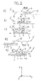
- insulating element 6 which has three functional openings, namely two coating openings 18, 18' and between the coating openings 18, 18 'arranged exposure opening 19, which also serves as a heating opening 20.
- Fig. 3a The build platform 2, driven by the drive device 15, moves in the x-direction below the first coating opening 18 of the insulating element 6. Building material 4 for a layer n is applied to the building platform 2.
- Fig. 3b the build platform 2 continues to move in the x-direction.
- the building material 4 applied shortly before is preheated to a temperature below the sintering temperature.
- heat radiation 26 is radiated from the radiation source 25 in the direction of the building material.
- the thermal radiation 26 passes through the insulating element 6 through the exposure and heating openings 19, 20 and is irradiated directly into the building material in the region of this opening.
- the heat radiation 26 is radiated from the reflective underside 22 of the insulating member 6 into a reflection region 23 between the first coating opening 18 and the exposure and heating opening 19, 20 as reflective heat radiation 11 in the building material.
- additional heat energy is introduced into an adjacent, previously preheated object area with the aid of the laser beam 8 through the exposure opening 19, as a result of which the powder particles melt.
- Fig. 3c the build platform 2 continues to move in the x-direction. Before the build platform 2 reaches the second coating opening 18 ', it is, driven by the drive device 5, moved in the z-direction a required distance down. Building material 4 for a further layer n + 1 is applied through the second coating opening 18 '. Shortly before, the object area below the reflection area 23 ', which lies between the exposure opening 19 and the second coating opening 18', was reheated by radiated and reflected heat radiation 11.
- Fig. 3d the build platform 2 has reached its one reversal point.
- the layers n and n + 1 were generated. Since no exposure and heating opening 19, 20 more about the build platform 2 is arranged, at this moment no laser irradiation takes place.
- the application of building material 4 takes place only as long as at least one of the two coating openings 18, 18 'is arranged above the building platform 2.
- Fig. 3e The build platform 2 moves in the x-direction, opposite to the first movement, under the insulating member 6 therethrough. With the aid of the second coating opening 18 ', a new material application for the next n + 2 layer has already taken place, as well as a preheating of the building material with the aid of irradiated and reflected thermal radiation 11 in an object area below the reflection area 23 "adjacent to the coating opening 18'. Previously, the build platform 2 was again moved down a required distance in the z-direction, driven by the drive device 5.
- the exposure and heating opening 19, 20 are subjected to local irradiation with the laser beam 8 for solidifying the structure to be produced In the case of a further movement of the build-up platform 2, a material application for the layer n + 3 will occur shortly through the first coating opening 18.
- Fig. 4 an embodiment is illustrated in which the radiation 8 from two simultaneously operated radiation sources 7, 14 impinges on the exposure layer 3 released from this exposure opening 19 through a common exposure opening 19.
- the insulating element 6 is shown transparently, moreover, only a single functional opening, the exposure opening 19, is shown.
- Each radiation source 7, 14 is associated with a target area 29, 30, this association being symbolic with broken auxiliary lines is pictured.
- the two target areas 29, 30 overlap to form an overlap area 31.
- the actuation of the at least two radiation sources 7, 14 which may again be lasers, is carried out by a correspondingly designed drive and control device 21 such that there is a minimum total processing time of the building material results.
- each radiation source 7, 14 moves on a defined path 32 in the x and / or y direction, as for the radiation source 14 in FIG Fig. 4 indicated.
- a coating opening 18 is provided between two exposure openings 19, 19 'so that bidirectional exposure is possible by exposing the layer n through the coating opening 18 when the build platform 2 moves in the x-direction through the exposure opening 19 lying in the direction of movement behind the coating opening 18 ( Fig. 5a
- the exposure of the next layer n + 1 already takes place through the exposure opening 19 'then lying behind the coating opening 18 in the direction of movement after material has previously been applied through the coating opening 18 (FIG. Fig. 5b ).
Abstract
Die Erfindung betrifft eine Vorrichtung (1) sowie ein Verfahren zum Herstellen dreidimensionaler Objekte (3) durch selektives Verfestigen eines schichtweise aufgebrachten Aufbaumaterials (4). Um den Herstellungsprozeß zu verbessern, insbesondere den Wärmeeintrag zu optimieren, wird die Verwendung eines Isolierelements (6) mit wenigstens zwei Funktionsöffnungen (18, 19) vorgeschlagen, wobei eine der wenigstens zwei Funktionsöffnungen als Materialdurchlaß (18) und eine andere der wenigstens zwei Funktionsöffnungen gleichzeitig als Strahlungsdurchlaß (19, 20) dient.The invention relates to a device (1) and to a method for producing three-dimensional objects (3) by selectively solidifying a build-up material (4) applied in layers. In order to improve the production process, in particular to optimize the heat input, the use of an insulating element (6) with at least two functional openings (18, 19) is proposed, one of the at least two functional openings as material passage (18) and another of the at least two functional openings simultaneously serves as a radiation passage (19, 20).
Description
Die Erfindung betrifft eine Vorrichtung sowie ein Verfahren zum Herstellen dreidimensionaler Objekte durch selektives Verfestigen eines schichtweise aufgebrachten Aufbaumaterials.The invention relates to a device and a method for producing three-dimensional objects by selectively solidifying a build-up material applied in layers.
Aus dem Stand der Technik sind Vorrichtungen und Verfahren zur Herstellung dreidimensionaler Objekte durch selektives Verfestigen eines schichtweise aufgetragenen Aufbaumaterials in großer Zahl bekannt. Zu nennen sind hier beispielsweise das Lasersintern oder das Selektive Maskensintern. Anlagen, mit denen ein solches Schichtbauverfahren durchgeführt wird, werden auch als Rapid Prototyping-Systeme bezeichnet. Diese Schichtbauverfahren dienen zur Herstellung von schichtweise aufgebauten Bauteilen aus verfestigbarem Material, wie Harz, Kunststoff, Metall oder Keramik, und werden beispielsweise zur Fertigung von technischen Prototypen verwendet. Dabei können mit Hilfe einer additiven Fertigungsmethode dreidimensionale Objekte direkt aus CAD-Daten hergestellt werden.From the prior art devices and methods for producing three-dimensional objects by selectively solidifying a layered build-up material in large numbers are known. For example, laser sintering or selective mask sintering can be mentioned here. Systems with which such a layer construction process is carried out are also referred to as rapid prototyping systems. These layer construction methods are used to produce layered components made of solidifiable material, such as resin, plastic, metal or ceramic, and are used for example for the production of technical prototypes. With the aid of an additive manufacturing method, three-dimensional objects can be produced directly from CAD data.
Bei einem solchen Schichtbauverfahren erfolgt der Aufbau der Objekte schichtweise, d. h. es werden Schichten eines Aufbaumaterials sukzessive übereinander aufgetragen. Vor dem Aufbringen der jeweils nächsten Schichten werden die dem zu fertigenden Objekt entsprechenden Stellen in den jeweiligen Schichten selektiv verfestigt. Das Verfestigen erfolgt beispielsweise durch lokales Erhitzen eines zumeist pulverförmigen Schichtrohmaterials mit Hilfe einer Strahlungsquelle. Indem gezielt Strahlung in geeigneter Weise in die gewünschten Bereiche eingebracht wird, kann eine exakt definierte, beliebig geartete Objektstruktur erzeugt werden. Dabei ist auch die Schichtdicke einstellbar. Ein solches Verfahren ist insbesondere zur Herstellung von dreidimensionalen Körpern verwendbar, indem mehrere dünne, individuell gestaltete Schichten aufeinanderfolgend erzeugt werden.In such a layer construction method, the structure of the objects takes place in layers, ie layers of a building material are successively applied one above the other. Before applying the respective next layers, the points corresponding to the object to be manufactured in the respective layers are selectively solidified. The solidification takes place, for example, by local heating of a mostly pulverulent layer raw material with the aid of a radiation source. By deliberately introducing radiation into the desired regions in a suitable manner, an exactly defined, arbitrary type of object structure can be generated. In this case, the layer thickness is adjustable. Such a method is particularly useful for making three-dimensional bodies by sequentially creating a plurality of thin, individually designed layers.
Typischerweise wird das zu verfestigende Aufbaumaterial auf eine Temperatur vorgewärmt, die unterhalb der Verarbeitungstemperatur liegt. Mit Hilfe eines zusätzlichen Energieeintrags wird anschließend die Verarbeitungstemperatur erreicht.Typically, the build-up material to be consolidated is preheated to a temperature which is below the processing temperature. With the help of an additional energy input, the processing temperature is then reached.
Beispielsweise wird ein Kunststoffmaterial bei einem Lasersinterprozeß auf eine Temperatur unterhalb der Sintertemperatur vorgewärmt. Die durch den Laser eingebrachte Energie trägt dann lediglich die Differenzwärmemenge zum Aufschmelzen der Pulverteilchen bei.For example, a plastic material is preheated to a temperature below the sintering temperature during a laser sintering process. The energy introduced by the laser then only contributes the amount of differential heat for melting the powder particles.
Das Vorwärmen erfolgt in vielen Fällen über ein Erwärmen der Aufbauplattform. Mit ansteigender Bauteilhöhe nimmt bei einem solchen Vorwärmen "von unten" jedoch der Wärmestrom der Vorwärmung durch Verluste und zunehmendes Volumen der Pulverschüttung ab.The preheating is done in many cases by heating the build platform. With increasing component height decreases in such a preheating "from below" but the heat flow of the preheating by losses and increasing volume of the powder bed.
Auch andere Verfahren führen zu einer unerwünschten unregelmäßigen Temperaturverteilung in dem Aufbaumaterial. Dies trifft insbesondere auch auf solche Verfahren zu, bei denen das Vorwärmen über eine Wärmezufuhr "von oben" erfolgt. Dabei werden zeitweise beheizbare Einrichtungen über der Aufbauschicht plaziert. Durch komplizierte Steuerungen der Heizkurve und andere aufwendige Maßnahmen wird versucht, eine gleichmäßige Temperaturverteilung in dem vorzuwärmenden Aufbaumaterial zu erreichen.Other methods also lead to an undesirable irregular temperature distribution in the building material. This applies in particular to those processes in which the preheating via a heat supply "from above" takes place. In this case, temporarily heated devices are placed over the build-up layer. Through complicated control of the heating curve and other complex measures is trying to achieve a uniform temperature distribution in the pre-heated building material.
Eine Aufgabe der vorliegenden Erfindung ist es, den Herstellungsprozeß zu verbessern, insbesondere den Wärmeeintrag zu optimieren.An object of the present invention is to improve the manufacturing process, in particular to optimize the heat input.
Diese Aufgabe wird durch eine Vorrichtung nach Anspruch 1 bzw. durch ein Verfahren nach Anspruch 10 gelöst. Vorteilhafte Ausführungen der Erfindung sind in den Unteransprüchen angegeben. Die im Folgenden im Zusammenhang mit der Vorrichtung erläuterten Vorteile und Ausgestaltungen gelten sinngemäß auch für das erfindungsgemäße Verfahren und umgekehrt.This object is achieved by a device according to
Die Erfindung schlägt vor, die aus dem Stand der Technik bekannte Vorgehensweise einer getakteten Herstellung, bei der innerhalb eines Taktes nach einem Materialauftrag zunächst ein Vorwärmen und anschließend ein selektives Verfestigen erfolgt, bevor in einem sich anschließenden neuen Takt erneut ein Materialauftrag vorgenommen wird, nicht mehr weiterzuverfolgen. Statt dessen schlägt die Erfindung einen kontinuierlichen Herstellungsprozeß vor, bei dem das Aufbringen des Aufbaumaterials, das Vorwärmen und das selektive Verfestigen durch lokales Erhitzen des Aufbaumaterials gleichzeitig erfolgt, und zwar an unterschiedlichen Stellen ein und desselben herzustellenden Objektes bzw. auch an mehreren Objekten gleichzeitig, sofern mehrere Objekte auf der Aufbauplattform hergestellt werden.The invention proposes the procedure known from the state of the art of clocked production in which, within one cycle after a material application, first a preheating and then a selective solidification takes place before a material application is carried out again in a subsequent new cycle pursue. Instead, the invention proposes a continuous production process, in which the application of the building material, the preheating and the selective solidification by local heating of the building material takes place simultaneously, namely at different locations of one and the same object to be produced or on several objects at the same time, if several objects are produced on the build platform.
Die erfindungsgemäße Vorrichtung umfaßt eine in einer x-y-Ebene angeordnete Aufbauplattform, auf der wenigstens ein dreidimensionales Objekt schichtweise erzeugt wird, wenigstens eine Vorwärmstrahlungsquelle zum Eintragen von Wärmeenergie in das Aufbaumaterial, wenigstens eine Verfestigungsstrahlungsquelle zum selektiven Verfestigen von Aufbaumaterial durch lokales Erhitzen sowie ein die Aufbauplattform zumindest teilweise überdeckendes Isolierelement . Das Isolierelement weist wenigstens zwei gleichzeitig verwendbare Funktionsöffnungen auf, wobei eine der wenigstens zwei Funktionsöffnungen als Materialdurchlaß und eine andere der wenigstens zwei Funktionsöffnungen als Strahlüngsdurchlaß ausgebildet ist. Erfindungsgemäß umfaßt die Vorrichtung eine Anzahl Antriebseinrichtungen zum Erzeugen von unabhängigen voneinander steuerbaren Relativbewegungen in x- und/oder y-Richtung zwischen wenigstens zwei der drei folgenden Komponenten der Vorrichtung: der Aufbauplattform, dem Isolierelement, der wenigstens einen Verfestigungsstrahlungsquelle.The inventive apparatus comprises a build platform arranged in an xy plane on which at least one three-dimensional object is generated in layers, at least one preheat radiation source for introducing heat energy into the build material, at least one solidification radiation source for selectively strengthening build material by local heating, and at least one build platform partially overlapping Insulating element. The insulating element has at least two simultaneously usable function openings, wherein one of the at least two function openings is designed as a material passage and another of the at least two function openings is designed as a radiation passage. According to the invention, the apparatus comprises a number of drive means for generating independent mutually controllable relative movements in the x and / or y direction between at least two of the three following components of the apparatus: the building platform, the insulating member, the at least one solidification radiation source.
Entsprechend umfaßt das erfindungsgemäße Verfahren die Schritte: schichtweises Erzeugen des wenigstens einen dreidimensionalen Objektes auf einer in einer x-y-Ebene angeordneten Aufbauplattform, Eintragen von Wärmeenergie in das Aufbaumaterial mit Hilfe der wenigstens einen Vorwärmstrahlungsquelle, lokales Erhitzen von Aufbaumaterial durch die wenigstens eine Verfestigungsstrahlungsquelle zum Zweck des selektiven Verfestigens sowie gleichzeitiges Durchlassen von Aufbaumaterial und Strahlungsenergie durch ein die Aufbauplattform zumindest teilweise überdeckendes Isolierelement, unter Verwendung von wenigstens zwei Funktionsöffnungen. Erfindungsgemäß umfaßt das Verfahren mittels einer Anzahl Antriebseinrichtungen das Erzeugen unabhängig voneinander ansteuerbarer Relativbewegungen in x- und/oder y-Richtung zwischen wenigstens zwei der drei folgenden Komponenten der Vorrichtung: der Aufbauplattform, dem Isolierelement, der wenigstens einen Verfestigungsstrahlungsquelle.Accordingly, the method according to the invention comprises the steps of: layering the at least one three-dimensional object on a build platform arranged in an xy plane, introducing heat energy into the build material by means of the at least one preheat radiation source, local heating of build material by the at least one solidification radiation source for the purpose of selective solidification and simultaneous passage of building material and radiation energy through an insulating at least partially overlapping the construction platform, using at least two functional openings. According to the invention, the method comprises by means of a number of drive means generating independently controllable relative movements in the x and / or y direction between at least two of the three following components of the device: the build platform, the insulating element, the at least one solidification radiation source.
Anders als bei früheren Lösungen ist bei der vorliegenden Erfindung zum Vorwärmen des Aufbaumaterials bzw. zum Nachheizen ein die Aufbauplattform größtenteils überdeckendes Heizelement, beispielsweise in Gestalt einer massiven, mit Heizmodulen versehenen Heizplatte, nicht mehr notwendig. Zum Vorwärmen des Aufbaumaterials bzw. zum Nachheizen dient statt dessen die wenigstens eine Vorwärmstrahlungsquelle, beispielsweise in Form eines Infrarot-Strahlers oder eines anderen geeigneten Wärmestrahlers. Die Vorwärmstrahlungsquelle nuß die Aufbauplattform nicht mehr zu einem Großteil überdecken. Es ist ausreichend, wenn die wenigstens eine Vorwärmstrahlungsquelle oberhalb eines die Aufbauplattform zumindest teilweise überdeckenden Isolierelements angebracht ist, das erfindungsgemäß das Einbringen der Strahlung zum Vorwärmen bzw. Nachheizen unterstützt. Das Isolierelement ist wärmeisolierend und besteht daher vollständig oder zumindest teilweise aus einem wärmeisolierenden Material. Oder aber das Isolierelement stellt die gewünschte Isoliereigenschaft durch andere Maßnahmen sicher, beispielsweise durch eine geeignete Oberflächenbeschichtung. Das Isolierelement ist dabei derart ausgeführt, daß es in seiner Betriebsposition oberhalb des aufzubauenden Objektes einen Raum zwischen dem Objekt und sich selbst wärmeisolierend nach oben begrenzt. Die Hauptfunktion des Isolierelements ist mit anderen Worten die Bildung einer wärmeisolierenden Begrenzung des Zwischenraumes zu dem Aufbauobjekt. Darüber hinaus unterstützt es die Wärmezufuhr zu dem Objekt. Dies erfolgt jedoch immer nur in Verbindung mit Energie, die bereits von einer Wärmequelle (Strahlungsquelle) abgegeben wurde. Diese Wärmequelle ist typischerweise über dem Isolierelement angeordnet. Die von dort abgegebene Wärmestrahlung wird von dem Isolierelement lediglich zu dem Objekt durchgelassen und/oder reflektiert. Das Isolierelement ist rein passiv, strahlt also nicht selbst.Unlike previous solutions, in the present invention, preheating of the building material or post-heating is required a heating platform which largely covers the construction platform, for example in the form of a solid heating plate provided with heating modules, is no longer necessary. For preheating the build-up material or for reheating, the at least one preheat radiation source, for example in the form of an infrared radiator or another suitable heat radiator, is used instead. The preheat radiation source no longer covers the build platform to a large extent. It is sufficient if the at least one preheat radiation source is mounted above an insulating element which at least partially covers the build-up platform and which according to the invention supports the introduction of the radiation for preheating or reheating. The insulating element is heat-insulating and therefore consists completely or at least partially of a heat-insulating material. Or the insulating element ensures the desired insulating property by other measures, for example by a suitable surface coating. The insulating element is designed such that it defines a space between the object and itself heat-insulating upwards in its operating position above the object to be built. In other words, the main function of the insulating element is the formation of a heat-insulating boundary of the intermediate space to the building object. In addition, it supports the heat supply to the object. However, this is always done only in conjunction with energy that has already been released from a heat source (radiation source). This heat source is typically disposed over the insulating member. The heat radiation emitted from there is transmitted and / or reflected by the insulating element only to the object. The insulating element is purely passive, so does not radiate itself.
Es ist für die Funktionsweise des Isolierelements von Vorteil, wenn das Isolierelement von den verwendeten Wärmequellen räumlich getrennt ist, wie dies in den bevorzugten Ausführungsformen der Erfindung der Fall ist. Das Isolierelement ist dann von den Strahlungsquellen beabstandet angeordnet und nicht Teil einer der Strahlungsquellen. Das Isolierelement ist dann mit anderen Worten ein von den Strahlungsquellen getrenntes, separates Bauteil.It is for the operation of the insulating advantageous if the insulating element of the heat sources used is spatially separated, as is the case in the preferred embodiments of the invention. The insulating element is then spaced from the radiation sources and not part of one of the radiation sources. In other words, the insulating element is a separate component separate from the radiation sources.
Das Isolierelement weist unabhängig von seiner Isolierfunktion wenigstens zwei gleichzeitig verwendbare Funktionsöffnungen auf, wobei die eine Funktionsöffnung als Materialdurchlaß und die anderen Funktionsöffnung als Strahlungsdurchlaß dient. Die Öffnungen dienen mithin also einerseits als Beschichtungsöffnung zum Aufbringen von Aufbaumaterial auf die Aufbauplattform und andererseits als Heizöffnung zum Vorwärmen bzw. Nachheizen des Aufbaumaterials mit von der Vorwärmstrahlungsquelle abgegebener Wärmestrahlung bzw. als Belichtungsöffnung zum lokalen Erhitzen des Aufbaumaterials zum Zweck seiner Verfestigung. Wird ein solches Isolierelement in geeigneter Weise relativ zu der Aufbauplattform bewegt, kann ein gleichzeitiges Aufbringen von Aufbaumaterial, Vorwärmen und selektives Verfestigen erfolgen und damit ein nicht getaktetes, ununterbrochenes Herstellen des wenigstens einen Objektes. Der Aufbau des Objektes bzw. der Objekte erfolgt mit anderen Worten kontinuierlich, wobei die Aufbaugeschwindigkeit durch die Relativbewegung zwischen Aufbauplattform und Isolierelement bestimmt wird. Die geometrische Anordnung der sich in unterschiedlichen Herstellungsprozeßphasen befindenden Objektbereiche, insbesondere der Abstand dieser Objektbereiche zueinander, wird durch die Anordnung der Funktionsöffnungen in dem Isolierelement bestimmt, insbesondere durch den Abstand dieser Funktionsöffnungen zueinander.Irrespective of its insulating function, the insulating element has at least two function openings which can be used simultaneously, one serving as a material passage and the other functioning as a radiation passage. The openings therefore serve, on the one hand, as a coating opening for applying building material to the building platform and, on the other hand, as a heating opening for preheating or reheating the building material with heat radiation emitted by the preheating radiation source or as an exposure opening for local heating of the building material for the purpose of solidifying it. If such an insulating element is moved in a suitable manner relative to the building platform, a simultaneous application of building material, preheating and selective solidification can take place and thus a non-clocked, uninterrupted production of the at least one object. The structure of the object or of the objects takes place in other words continuously, wherein the body speed is determined by the relative movement between the building platform and insulating. The geometrical arrangement of the object areas located in different production process phases, in particular the distance of these object areas from one another, is determined by the arrangement of the function openings in the insulating element, in particular by the distance of these function openings from each other.
Beispielsweise kann in einem ersten Objektbereich das Aufbaumaterial in Form einer frisch aufgebrachten Pulverschüttung durch das Isolierelement vorgewärmt werden, während in einem in Bewegungsrichtung hinter dem ersten Objektbereich angeordneten zweiten Objektbereich mit Hilfe von durch eine Belichtungsöffnung durchtretender Strahlungsenergie gerade eine Schicht n verfestigt wird. Zeitgleich erfolgt in einem dritten Objektbereich, der in Bewegungsrichtung hinter dem zweiten Objektbereich liegt, ein Nachheizen der dort kurz zuvor verfestigten Aufbauschicht n durch die wenigstens eine Vorwärmstrahlungsquelle bzw. durch das mit der Vorwärmstrahlungsquelle zusammenwirkende Isolierelement, während in einem hinter dem dritten Objektbereich liegenden vierten Objektbereich durch eine Beschichtungsöffnung hindurchgeführtes weiteres Aufbaumaterial für eine nächste Schicht n+1 auf die bereits vorhandene Schicht n aufgebracht wird. Die Objektbereiche können dabei Bereiche eines Objektes oder aber auch Bereiche unterschiedlicher Objekte sein, wenn mehrere Objekte auf der Aufbauplattform angeordnet sind.For example, in a first object area, the building material in the form of a freshly applied powder bed can be preheated by the insulating element, while in a second object area arranged in the direction of movement behind the first object area a layer n is just solidified by means of radiation energy passing through an exposure opening. At the same time, in a third object region, which lies behind the second object region in the direction of movement, reheating of the build-up layer n solidified there shortly before is effected by the at least one preheat radiation source or by the insulating element cooperating with the preheat radiation source, while in a fourth object region located behind the third object region further build-up material passed through a coating opening for a next layer n + 1 is applied to the already existing layer n. The object areas may be areas of an object or even areas of different objects, if several objects are arranged on the build platform.
Die Wärmezufuhr für das Vorwärmen erfolgt "von oben", wodurch die Nachteile einer Wärmezufuhr über die Aufbauplattform nicht auftreten. Zugleich erfolgt die Wärmezufuhr vorzugsweise nicht nur zeitweise, nämlich nicht nur dann, wenn sich die wenigstens eine Vorwärmstrahlungsquelle wie im Stand der Technik für kurze Zeit oberhalb der Aufbauschicht befindet, sondern, ermöglicht durch die neuartige kontinuierliche Arbeitsweise, insbesondere aufgrund der Isolier- und/oder Reflexionseigenschaften des Isolierelements, dauerhaft. Damit wird auf einfache Art und Weise eine Optimierung des Wärmeeintrags erreicht. Zugleich wird der Herstellungsprozeß insgesamt verbessert.The heat supply for the preheating is done "from above", whereby the disadvantages of heat supply via the build platform do not occur. At the same time, the heat is preferably not only temporarily, namely not only when the at least one Vorwärmstrahlungsquelle as in the prior art for a short time above the build-up layer, but, made possible by the novel continuous operation, in particular due to the insulating and / or Reflection properties of the insulating element, durable. Thus, an optimization of the heat input is achieved in a simple manner. At the same time, the manufacturing process is improved overall.
Darüber hinaus kann in bevorzugten Ausführungsformen der Erfindung nicht nur die Verfestigungsstrahlungsquelle, sondern auch die Vorwärmstrahlungsquelle bewegt werden, nämlich in x- und/oder y-Richtung zur Positionierung der Vorwärmstrahlungsquelle relativ zu dem Isolierelement bzw. der Aufbauplattform und/oder senkrecht dazu in z-Richtung zur Änderung des vertikalen Abstandes mit dem Ziel einer veränderten Abstrahlcharakteristik und/oder einer veränderbaren Temperierung. Vorzugsweise ist die wenigstens eine Vorwärmstrahlungsquelle außerdem kontrolliert ansteuerbar zur Veränderung der von ihr abgegebenen Strahlungsleistung.In addition, in preferred embodiments of the invention, not only the solidification radiation source but also the preheat radiation source may be moved, namely in the x and / or y direction for positioning the preheat radiation source relative to the insulating member or the building platform and / or perpendicularly thereto. Direction for changing the vertical distance with the aim of a modified radiation characteristic and / or a variable temperature. Preferably, the at least one preheat radiation source is also controllably controllable for changing the radiation power output by it.
Durch das Erzeugen mehrerer Relativbewegungen zwischen den beteiligten Komponenten Aufbauplattform, Isolierelement sowie der wenigstens einen Verfestigungsstrahlungsquelle und ggf. der wenigstens einen Aufwärmstrahlungsquelle können die zeitlichen Einwirkungen der verschiedenen Prozeßbedingungen in den jeweiligen Verfahrensschritten auf einfache Weise und sehr flexibel aufeinander abgestimmt und optimiert werden. Dadurch ist der Herstellungsprozeß insgesamt weiter optimierbar.By generating a plurality of relative movements between the components involved construction platform, insulating and at least one solidification radiation source and possibly the at least one Aufwärmstrahlungsquelle the temporal effects of the different process conditions in the respective process steps in a simple manner and very flexible matched and optimized. As a result, the overall manufacturing process can be further optimized.
Als besonders vorteilhaft hat sich eine Entkopplung der Bewegung des Strahlungsdurchlasses von der Bewegung der Verfestigungsstrahlungsquelle erwiesen. Mit anderen Worten kann sich die Verfestigungsstrahlungsquelle mit einer anderen Geschwindigkeit über die Aufbauplattform bzw. das sich darauf befindenden Aufbaumaterial bewegen als das Isolierelement.Decoupling of the movement of the radiation passage from the movement of the solidification radiation source has proven to be particularly advantageous. In other words, the solidification radiation source may move at a different speed over the build platform or buildup material thereon than the isolation element.
Insbesondere dann, wenn das Einbringen von Strahlungsenergie durch die Belichtungsöffnung erfolgt, ohne daß diese Öffnung vollständig ausgeleuchtet wird, sondern wenn statt dessen eine gezielte Bestrahlung des unterhalb dieser Öffnung angeordneten Aufbaumaterials innerhalb der Grenzen dieser Öffnung erfolgt, beispielsweise derart, daß ein Laser das Aufbaumaterial entlang einer definierten Bahnkurve erhitzt, läßt sich erfindungsgemäß die Verfestigungsstrahlungsquelle unabhängig von der Bewegung des Isolierelements und damit unabhängig von der Bewegung der Belichtungsöffnung in dem von dem Strahlungsdurchlaß bereitgestellten Öffnungsbereich so bewegen, daß die Strahlungsleistung besonders effizient eingebracht werden kann.In particular, when the introduction of radiation energy through the exposure opening, without this opening is fully illuminated, but instead, if a targeted irradiation of the arranged below this opening building material within the limits of this opening, For example, such that a laser heats the building material along a defined trajectory, the solidification radiation source can be moved independently of the movement of the insulating member and thus independently of the movement of the exposure opening in the opening area provided by the radiation passage so that the radiation power can be introduced particularly efficiently can.
Dies wird in einer bevorzugten Ausführungsform der Erfindung dadurch verwirklicht, daß die Vorrichtung neben einer ersten Antriebseinrichtung zum Erzeugen einer ersten Relativbewegung zwischen der Aufbauplattform und dem Isolierelement in x- und/oder y-Richtung eine zweite Antriebseinrichtung zum Erzeugen einer von der ersten Relativbewegung unabhängigen zweiten Relativbewegung zwischen der Verfestigungsstrahlungsquelle und dem Isolierelement in x- und/oder y-Richtung aufweist. Erforderlichenfalls ist eine dritte Antriebseinrichtung vorgesehen zum Erzeugen einer unabhängigen Relativbewegung der Vorwärmstrahlungsquelle.This is realized in a preferred embodiment of the invention in that the device in addition to a first drive means for generating a first relative movement between the building platform and the insulating in the x and / or y direction, a second drive means for generating a second independent of the first relative movement second Has relative movement between the solidification radiation source and the insulating in the x and / or y direction. If necessary, a third drive means is provided for generating an independent relative movement of the preheat radiation source.
Zur weiteren Optimierung des Prozesses, insbesondere für ein besonders effizientes Einbringen der Strahlungsleistung zum Verfestigen des Aufbaumaterials, kann zusätzlich die Form, die Anordnung und/oder die Größe der Belichtungsöffnungen, insbesondere die Schlitzbreite in der Hauptbewegungsrichtung, beispielsweise der x-Richtung, an den jeweiligen Prozeß anpaßbar sein bzw. auch während des Herstellungsprozesses variiert werden. Damit kann beispielsweise erreicht werden, daß der sich jeweils unmittelbar unterhalb einer Belichtungsöffnung befindende, nicht von der Vorwärmstrahlungsquelle bzw. dem Isolierelement erwärmte Bereich möglichst klein ist. Zur weiterführenden Optimierung kann die Geschwindigkeit einzelner Komponenten, insbesondere die Geschwindigkeit des Isolierelements und damit der Belichtungsöffnungen und/oder die Geschwindigkeit der Strahlungsquelle(n) während des Herstellungsprozesses variiert werden, insbesondere aufeinander abgestimmt werden.To further optimize the process, in particular for a particularly efficient introduction of the radiation power for solidifying the building material, additionally the shape, the arrangement and / or the size of the exposure openings, in particular the slot width in the main movement direction, for example the x-direction, to the respective Be adaptable process or be varied during the manufacturing process. Thus, it can be achieved, for example, that the area located immediately below an exposure opening, not heated by the preheat radiation source or the insulating element, is as small as possible. For further optimization, the speed of individual components, in particular the speed of the Insulating element and thus the exposure openings and / or the speed of the radiation source (s) are varied during the manufacturing process, in particular matched to each other.
Darüber hinaus ermöglicht es die vorliegende Erfindung, sich von der Notwendigkeit einer gleichmäßigen Temperaturverteilung zu lösen. Da an unterschiedlichen Stellen das Herstellungsverfahren unterschiedlich weit fortgeschritten ist, können an unterschiedlichen Stellen unterschiedliche Temperaturen von Vorteil sein. So kann beispielsweise in einem Bereich eine Vorwärmtemperatur zum Vorbereiten des Aufbaumaterials auf die bevorstehende lokale Erhitzung vorteilhaft sein; in einem benachbarten Bereich kann hingegen eine Nachheiztemperatur vorliegen, wie sie zum Erreichen bestimmter Eigenschaften der bereits verfestigten Schicht vorteilhaft ist, beispielsweise um Verzug zu verhindern.Moreover, the present invention makes it possible to solve the need for a uniform temperature distribution. Since the production process has advanced at different points at different points, different temperatures can be advantageous at different points. For example, in one area a preheating temperature for preparing the building material for the upcoming local heating may be advantageous; On the other hand, in a neighboring area, a reheating temperature may be present, as is advantageous for achieving certain properties of the already solidified layer, for example to prevent distortion.
Da das Isolierelement dauerhaft zur Verfügung steht, kann eine solche definierte ungleichmäßige Temperaturverteilung auf besonders einfache Weise verwirklicht werden. In einer vorteilhaften Ausführungsform der Erfindung weist das Isolierelement mehrere unterschiedlich temperierbare Bereiche auf. Dies wird beispielsweise mit Hilfe mehrerer, voneinander unabhängig betreibbarer Vorwärmstraklungsquellen erreicht.Since the insulating member is permanently available, such a defined uneven temperature distribution can be realized in a particularly simple manner. In an advantageous embodiment of the invention, the insulating element on several different temperature-controlled areas. This is achieved, for example, with the aid of several, independently operable Vorwärmstraklungsquellen.
Die Vorwärmstrahlungsquellen zur Bereitstellung von Wärmeenergie sind insbesondere in Form von oberhalb des Isolierelements angeordneten Wärmequellen ausgeführt. Wenigstens eine der Funktionsöffnungen ist als Heizöffnung zum Eintragen von Wärmeenergie in das Aufbaumaterial ausgebildet. Dabei kann es sich bei der Heizöffnung um eine Funktionsöffnung handeln, die bereits eine andere Funktion ausübt; beispielsweise kann ein bereits als Belichtungsöffnung dienender Strahlungsdurchlaß zugleich als Heizöffnung dienen.The preheating radiation sources for the provision of heat energy are designed in particular in the form of heat sources arranged above the insulating element. At least one of the functional openings is formed as a heating opening for introducing heat energy into the building material. In this case, the heating opening may be a function opening which already performs another function; for example For example, a radiation passage already serving as an exposure opening can simultaneously serve as a heating opening.
Für die Übertragung der Heizenergie auf das Aufbaumaterial besonders vorteilhaft hat sich eine Ausführungsform der Erfindung erwiesen, bei der das Isolierelement auf seiner in Richtung der Aufbauplattform weisenden Seite reflektierend ausgebildet ist. Das Isolierelement dient dann als Reflektor zur diffusen Reflexion von Wärmestrahlung. Es reflektiert die von der wenigstens einen Vorwärmstrahlungsquelle in Richtung des Aufbaumaterials eingebrachte Wärmestrahlung auf das Aufbaumaterial und/oder es reflektiert die in das Aufbaumaterial eingebrachte und von dem Aufbaumaterial weg reflektierte Wärmestrahlung zurück auf das Aufbaumaterial. Hierzu besteht das Isolierelement aus einem entsprechend reflektierendem Material oder das Isolierelement ist an seiner im Betriebszustand in Richtung der Aufbauplattform weisenden Unterseite mit einer Wärmestrahlung diffus reflektierenden Schicht versehen. Diese Schicht kann mittels einer Beschichtung auf das Isolierelement aufgebracht worden sein.For the transmission of heat energy to the building material particularly advantageous, an embodiment of the invention has been found in which the insulating element is formed on its pointing in the direction of the building platform side reflective. The insulating element then serves as a reflector for the diffuse reflection of heat radiation. It reflects the thermal radiation introduced by the at least one preheating radiation source in the direction of the building material onto the building material and / or reflects the thermal radiation introduced into the building material and reflected away from the building material back onto the building material. For this purpose, the insulating element consists of a correspondingly reflective material or the insulating element is provided with a heat radiation diffusely reflecting layer at its underside pointing in the operating state in the direction of the build-up platform. This layer may have been applied by means of a coating on the insulating element.
Es sind in erster Linie diese Reflexionseigenschaften des Isolierelementes, die es ermöglichen, anstelle eines teuren, aktiven, das Aufbaumaterial mehr oder weniger überdeckenden Heizelements ein preiswertes, passives Isolierelement in Verbindung mit oberhalb angeordneten Vorwärmstrahlungsquellen zu verwenden. Durch die Isoliereigenschaften und die Reflexionseigenschaften des Isolierelements läßt sich die gewünschte Wärmezufuhr in das Aufbaumaterial mit vergleichsweise einfachen konstruktiven Mitteln realisieren. Insbesondere kann mit Hilfe des Isolierelements, welches das herzustellende Objekt überdeckt und unmittelbar über der Oberfläche des Objektes angeordnet ist, die gewünschte Temperatur des Aufbaumaterials gehalten werden, ohne daß es Heizmodule im Inneren des Isolierelements bedarf.It is primarily these reflection properties of the insulating element, which make it possible, instead of an expensive, active, the building material more or less covering the heating element to use a low-cost, passive insulating in conjunction with above arranged Vorwärmstrahlungsquellen. Due to the insulating properties and the reflection properties of the insulating element, the desired heat input into the building material can be realized with comparatively simple structural means. In particular, with the help of the insulating element, which covers the object to be produced and is arranged directly above the surface of the object, the desired temperature of the building material be kept without heating modules required in the interior of the insulating.
Vorzugsweise ist das Isolierelement im wesentlichen plattenförmig, eben ausgebildet. Die Plattenform des Isolierelements ermöglicht zugleich eine besonders einfache Ausführung der Funktionsöffnungen. In einer bevorzugten Ausführungsform der Erfindung ist das Isolierelement als sehr dünne, ebene Platte ausgeführt.Preferably, the insulating element is substantially plate-shaped, flat. The plate shape of the insulating allows at the same time a particularly simple design of the function openings. In a preferred embodiment of the invention, the insulating element is designed as a very thin, flat plate.
In einer besonders bevorzugten Ausführungsform der Erfindung ist das Isolierelement als Folie ausgeführt. Dadurch läßt sich die Baugröße der Vorrichtung deutlich verringern. Aufgrund des gegenüber einer massiven Isolierplatte verringerten Gewichts einer Folie kann eine entsprechende Antriebseinrichtung des Isolierelements kleiner dimensioniert sein. Eine Änderung der Größe und/oder Anordnung der Funktionsöffnungen in dem Isolierelement ist besonders einfach möglich, da es sich vorzugsweise um eine flexible Folie handelt, die aufgerollt werden kann. Zugleich ist die Ausführung mit Folie platzsparend. Der benötigte Lagerraum für Isolierelemente ist vergleichsweise gering, da die Isolierelemente aufgerollt gelagert werden können. Ist das Isolierelement als Folie ausgeführt, kann die Folie mehrschichtig aufgebaut sein, mit einer unteren reflektierenden Schicht.In a particularly preferred embodiment of the invention, the insulating element is designed as a film. As a result, the size of the device can be significantly reduced. Due to the reduced weight of a film compared to a solid insulating plate, a corresponding drive device of the insulating element can be dimensioned smaller. A change in the size and / or arrangement of the function openings in the insulating element is particularly easy, since it is preferably a flexible film that can be rolled up. At the same time, the version with foil saves space. The required storage space for insulating elements is relatively low, since the insulating elements can be stored rolled up. If the insulating element is designed as a film, the film can be constructed in multiple layers, with a lower reflective layer.
Vorteilhafterweise sind Isolierelement und Aufbauplattform dabei derart ausgeführt, daß sie sich möglichst großflächig, vorzugsweise vollständig, überdecken bzw. während der Herstellungsprozesses möglichst großflächig, vorzugsweise vollständig, in Überdeckung miteinander gebracht werden können. In einer bevorzugten Ausführungsform der Erfindung ist das Isolierelement oberhalb der Aufbauplattform angeordnet. Das Isolierelement ist dabei von der jeweils obersten Aufbauschicht beabstandet. Das Aufwärmen erfolgt durch Wärmestrahlung.Advantageously, the insulating member and build platform are designed such that they cover as large as possible, preferably completely, or during the manufacturing process as large as possible, preferably completely, can be brought into coincidence with each other. In a preferred embodiment of the invention, the insulating element is arranged above the build platform. The insulating element is spaced from the uppermost build-up layer. The warm-up is done by heat radiation.
Befindet sich die Aufbauplattform innerhalb einer im Betriebszustand geschlossenen Prozeßkammer, dann kann das Isolierelement als Begrenzungswand der Prozeßkammer dienen. Mit anderen Worten wird in diesem Fall die Prozeßkammer durch das Isolierelement abgeschlossen. Das Isolierelement ist dann ein Teil der Prozeßkammer.If the build-up platform is located within a process chamber closed in the operating state, then the insulating element can serve as a boundary wall of the process chamber. In other words, in this case, the process chamber is closed by the insulating member. The insulating element is then a part of the process chamber.
Bei der Beschichtungsöffnung handelt es sich stets um eine tatsächliche Öffnung im Sinne eines Materialdurchbruchs. Für die Belichtungsöffnung und die Heizöffnung muß das Isolierelement hingegen nicht zwangsläufig durchbrochen sein. Die Belichtungs-bzw. Heizöffnung kann auch als ein Bereich geeigneten Materials in dem Grundkörper des Isolierelements ausgeführt sein, das sich für einen Strahlungsdurchgang eignet.The coating opening is always an actual opening in the sense of a material breakthrough. For the exposure opening and the heating opening, however, the insulating element does not necessarily have to be broken. The exposure or. Heating aperture may also be embodied as a portion of suitable material in the body of the insulating member which is suitable for a radiation passage.
In einer bevorzugten Ausführungsform der Erfindung erfolgt das Einbringen von Strahlungsenergie zum Verfestigen des Aufbaumaterials durch die Belichtungsöffnung, ohne daß diese Öffnung vollständig ausgeleuchtet wird. Statt dessen erfolgt eine gezielte Bestrahlung des unterhalb dieser Öffnung angeordneten Aufbaumaterials innerhalb der Grenzen dieser Öffnung. Die Strahlung kann dabei von einer oder mehreren Verfestigungsstrahlungsquellen stammen. Beispielsweise können zum lokalen Erhitzen des Aufbaumaterials ein oder mehrere Laserstrahlen innerhalb des durch die Funktionsöffnung bereitgestellten Fensters eine lineare Hin- und Herbewegung innerhalb der Funktionsöffnung vollführen oder aber der oder die Laserstrahlen werden, innerhalb des Fensters auf einer nichtlinearen Bahnkurve definiert geführt, jeweils in Abhängigkeit von der zu erzeugenden Struktur. Die Führung der Strahlung erfolgt mit Hilfe einer geeigneten Steuerung. Das zuvor auf eine Temperatur unterhalb der Verarbeitungstemperatur vorgewärmte Aufbaumaterial wird lokal weiter erhitzt. Mit Hilfe dieses zusätzlichen Energieeintrags wird die Verarbeitungstemperatur erreicht.In a preferred embodiment of the invention, the introduction of radiant energy for solidifying the building material through the exposure opening, without this opening is completely illuminated. Instead, there is a targeted irradiation of the building material arranged below this opening within the limits of this opening. The radiation can originate from one or more solidification radiation sources. For example, for locally heating the build material, one or more laser beams within the window provided by the function opening may perform a linear reciprocation within the function opening, or else the laser beam (s) within the window on one Defined non-linear trajectory out, depending on the structure to be generated. The guidance of the radiation takes place with the help of a suitable control. The build material previously preheated to a temperature below the processing temperature is further heated locally. With the help of this additional energy input, the processing temperature is reached.
In einer besonders vorteilhaften Ausführungsform der Erfindung werden zum Energieeintrag mindestens zwei Verfestigungsstrahlungsquellen verwendet, deren Strahlung gleichzeitig durch eine gemeinsame Belichtungsöffnung auf einen von dieser Belichtungsöffnung freigegebenen Bereich der darunterliegenden Aufbauschicht tritt. Durch die gleichzeitige Verwendung mehrerer Verfestigungsstrahlungsquellen kann das Einbringen der Strahlungsenergie besonders effizient erfolgen. Zugleich ermöglicht dies, wie nachfolgend beschrieben, eine weitergehende Optimierung der Energiezufuhr.In a particularly advantageous embodiment of the invention, at least two solidification radiation sources are used for energy input, the radiation of which simultaneously passes through a common exposure opening onto a region of the underlying build-up layer released from this exposure opening. By the simultaneous use of several solidification radiation sources, the introduction of the radiation energy can be carried out particularly efficiently. At the same time, this allows, as described below, a further optimization of the energy supply.
In einer besonders vorteilhaften Ausführungsform der Erfindung ist es vorgesehen, daß jeder Verfestigungsstrahlungsquelle ein von ihr zu bestrahlender Bereich der Aufbauschicht, nachfolgend als Zielbereich bezeichnet, zugeordnet ist. Dabei überlappen sich benachbarte Zielbdreiche zumindest teilweise, wobei sie einen Überlappbereich bilden.In a particularly advantageous embodiment of the invention, it is provided that each hardening radiation source is associated with an area of the build-up layer to be irradiated by it, referred to below as the target area. In this case, adjacent target domains overlap at least partially, forming an overlap region.
Mit anderen Worten werden, die mindestens zwei gleichzeitig betriebenen Verfestigunlgsstrahlungsquellen derart angesteuert, insbesondere derart in x- und/oder y-Richtung bewegt, daß sie Strahlungsenergie (auch) in wenigstens eine gemeinsame, d.h. von den mindestens zwei Verfestigungsstrahlungsquellen bestrahlte Fläche der Aufbauschicht, den Überlappbereich, einbringen. Dabei bestrahlen die wenigstens zwei Verfestigungsstrahlungsquellen den Überlappbereich entweder gleichzeitig oder nacheinander.In other words, the at least two simultaneously operated solidification radiation sources are driven in such a way, in particular in the x- and / or y-direction moves that radiation energy (also) in at least one common, ie irradiated by the at least two solidification radiation sources surface of the build-up layer Overlap area, bring in. there The at least two solidification radiation sources irradiate the overlap area either simultaneously or sequentially.
Die Ansteuerung der mindestens zwei Verfestigungsstrahlungsquellen erfolgt dabei vorzugsweise derart, daß sich aus der Art und Weise der Überlappung der Strahlungsbereiche eine minimale Gesamtbearbeitungsdauer des Aufbaumaterials ergibt, genauer gesagt, daß diejenige Zeitdauer minimal ist, die für das Einbringen der für ein Verfestigen des Aufbaumaterials benötigten Energie erforderlich ist. Dadurch wird die Gesamtdauer der Herstellung der dreidimensionalen Objekte verkürzt. Vorzugsweise erfolgt die Ansteuerung zugleich derart, daß die Betriebszeiten der einzelnen Strahlungsquellen minimiert werden.The control of the at least two solidification radiation sources is preferably carried out such that the manner of overlapping the radiation ranges a minimum total processing time of the building material results, more precisely, that the time is minimal, which is necessary for the introduction of the energy required for solidification of the building material is required. This shortens the overall duration of the production of the three-dimensional objects. Preferably, the control is at the same time such that the operating times of the individual radiation sources are minimized.
Zur Minimierung der Bearbeitungsdauer werden in einer bevorzugten Ausführungsform der Erfindung die zu belichtenden Flächen, die Zielbereiche, zunächst in einzelne Teilbereiche, nachfolgend als Flächensegmente bezeichnet, unterteilt oder es werden derartige Flächensegmente aus dem jeweiligen Zielbereich ausgewählt und auf diese Weise von Teilbereichen unterschieden, die nicht belichtet werden müssen. Beispielsweise wird der durch Form und Größe der Belichtungsöffnung vorgegebene, von mehreren Verfestigungsstrahlungsquellen gleichzeitig bestrahlbare Bereich in x- und y-Richtung segmentiert.In order to minimize the processing time, in a preferred embodiment of the invention, the areas to be exposed, the target areas, are initially divided into individual partial areas, hereinafter referred to as area segments, or such area segments are selected from the respective target area and thus distinguished from partial areas that do not have to be exposed. For example, the area predetermined by the shape and size of the exposure opening and simultaneously irradiated by a plurality of solidification radiation sources is segmented in the x and y directions.
Anschließend wird die benötigte Verweildauer der einzelnen Verfestigungsstrahlungsquellen in dem jeweiligen Flächensegment berechnet. Abschließend wird eine geeignete, vorzugsweise die schnellste Belichtungsstrategie ermittelt. Dabei werden diejenigen Wege ermittelt, welche die einzelnen Strahlungsquellen innerhalb des von dem Strahlungsdurchlaß bereitgestellten Fensters zurücklegen. Der Energieeintrag erfolgt beispielsweise dadurch, daß ein Laserstrahl linienförmig, beispielsweise unter Bildung von eng benachbarten geradlinigen Schraffurlinien, eine zeilenweise Abtastung bzw. Rasterung des betreffenden Flächenbereiches vornimmt, um einen Bereich der Aufbauschicht zu verfestigen. Dieses Belichtungsmuster kann von Schicht zu Schicht variieren.Subsequently, the required residence time of the individual solidification radiation sources in the respective area segment is calculated. Finally, a suitable, preferably the fastest exposure strategy is determined. In this case, those paths are determined which cover the individual radiation sources within the window provided by the radiation passage. The energy input takes place, for example, in that a laser beam makes a linear line, for example, forming closely adjacent straight-line hatching lines, a line-by-line scanning or screening of the surface area concerned in order to solidify a region of the build-up layer. This exposure pattern can vary from layer to layer.
Vorzugsweise erfolgt nicht nur das Ermitteln der Belichtungsstrategie für eine bestimmte Segmentierung unter dem Gesichtspunkt einer zeitlichen Optimierung des Herstellungsprozesses, sondern auch das Segmentieren selbst wird so durchgeführt, daß die spätere Belichtung besonders effizient erfolgen kann. Beispielsweise erfolgt das Segmentieren unter Berücksichtigung der Lage der Bewegungsachsen der Strahlungsquellen.Preferably, not only is the determination of the exposure strategy for a specific segmentation from the point of view of temporal optimization of the production process, but also the segmentation itself is carried out in such a way that the subsequent exposure can be carried out particularly efficiently. For example, the segmentation takes place taking into account the position of the axes of movement of the radiation sources.
Vorzugsweise erfolgt auch ein Ermitteln und Durchführen einer geeigneten Vorwärmstrategie in Bezug auf die einzelnen Flächensegmente, wobei sich "Vorwärmen" bzw. "Vorwärmstrategie" auch auf ein etwaiges Nachheizen, also das Einbringen von Wärmeenergie auf bereits verfestigtes Aufbaumaterial, beziehen soll.It is also preferable to determine and to carry out a suitable preheating strategy with respect to the individual surface segments, wherein "preheating" or "preheating strategy" should also refer to any post-heating, ie the introduction of thermal energy to already consolidated building material.
Die erfindungsgemäße Vorrichtung zum Herstellen dreidimensionaler Objekte umfaßt geeignete Mittel zum Segmentieren, zum Berechnen der Verweildauer und zum Ermitteln der Belichtungs- und/oder Vorwärmstrategie oder ist mit solchen Mitteln verbunden bzw. erhält entsprechende Informationen, insbesondere Steuerungsdaten zur Ansteuerung der Anzahl der Strahlungsquellen zur Verwirklichung der ermittelten Belichtungs- und/oder Vorwärmstrategie aus einer externen Datenquelle.The device according to the invention for producing three-dimensional objects comprises suitable means for segmenting, calculating the residence time and determining the exposure and / or preheating strategy, or is associated with such means or obtains corresponding information, in particular control data for controlling the number of radiation sources for realizing the determined exposure and / or preheating strategy from an external data source.
Die zur Steuerung der erfindungsgemäßen Vorrichtung verwendeten Steuerungsdaten umfassen ein Datenmodell zur Beschreibung der herzustellenden Objekte bzw. werden unter Verwendung eines solchen Datenmodells erzeugt. Das Datenmodell beschreibt dabei nicht nur die Aufteilung jedes Objektes in Aufbauschichten, sondern auch die Lage der Objekte auf der Aufbauplattform.The control data used to control the device according to the invention comprise a data model for describing the objects to be produced or are generated using such a data model. The data model describes not only the division of each object into building layers, but also the location of the objects on the build platform.
Mit Hilfe der vorliegenden Erfindung ist es möglich, das der Herstellung der dreidimensionalen Objekte zugrundeliegende Datenmodell so zu optimieren, daß die Anordnung der Objekte auf der Aufbauplattform bzw. die Lage der Objekte zueinander so gewählt ist, daß unter Berücksichtigung der Belichtungs- bzw. Vorwärmstrategie eine besonders effiziente Herstellung, insbesondere eine besonders schnelle Herstellung erfolgt. In einer besonders vorteilhaften Ausführungsform der Erfindung erfolgt also nicht nur eine optimale Wahl der jeweiligen individuellen Belichtungs- bzw. Vorwärmstrategie pro Aufbauschicht, insbesondere eine zeitliche Optimierung des Strahlungseintrags, sondern auch bereits zuvor eine das erfindungsgemäße Verfahren berücksichtigende Optimierung der Anordnung der herzustellenden Objekte auf der Aufbauplattform.With the aid of the present invention, it is possible to optimize the data model underlying the production of the three-dimensional objects in such a way that the arrangement of the objects on the build platform or the position of the objects relative to one another is selected so that, taking into account the exposure or preheating strategy particularly efficient production, in particular a particularly rapid production takes place. In a particularly advantageous embodiment of the invention, therefore, not only an optimal choice of the respective individual exposure or preheating strategy per build-up layer, in particular a temporal optimization of the radiation input, but also previously an optimization of the arrangement of the objects to be manufactured on the build platform taking into account the inventive method ,
In einer einfachen Variante der Erfindung sind Anordnung und Größe der Funktionsöffnungen unveränderlich. So hat es sich als vorteilhaft erwiesen, streifenförmige Funktionsöffnungen zu verwenden, die parallel zueinander liegen. Die Funktionsöffnungen sind dabei vorteilhafterweise senkrecht zu der Richtung der Relativbewegung, beispielsweise senkrecht zu der x- oder der y-Richtung, in dem Isolierelement angeordnet. Alternativ ist es möglich, daß die Funktionsöffnungen schräg, d.h. unter einem Winkel zu der Bewegungsrichtung, angeordnet sind. Bei der vorliegenden Erfindung von Vorteil ist es, daß die Form, Anordnung und Größe der Funktionsöffnungen an die Besonderheiten des Verfahrens angepaßt werden können. So können anstelle von streifen- oder schlitzförmigen Funktionsöffnungen für alle oder einzelne Funktionen beispielsweise auch lochförmige Funktionsöffnungen oder Funktionsöffnungen beliebiger anderer Form vorgesehen sein.In a simple variant of the invention, the arrangement and size of the functional openings are invariable. Thus, it has proven to be advantageous to use strip-shaped function openings which are parallel to one another. The function openings are advantageously arranged perpendicular to the direction of the relative movement, for example perpendicular to the x or the y direction, in the insulating element. Alternatively, it is possible that the function openings are arranged obliquely, ie at an angle to the direction of movement. In the present invention, it is advantageous that the shape, arrangement and size of the function openings to the Particularities of the process can be adapted. Thus, instead of strip or slot-shaped function openings for all or individual functions, for example, also hole-shaped function openings or function openings of any other shape can be provided.
In einer vorteilhaften Ausführungsform der Erfindung sind Form, Anordnung und/oder Größe der Funktionsöffnungen veränderbar. Beispielsweise kann es von Vorteil sein, die Größe der Belichtungsöffnung veränderbar auszuführen, insbesondere dann, wenn diese Funktionsöffnung als Blende dient, d. h. zur Begrenzung des Querschnitts der eingebrachten Strahlung. Ebenfalls kann es von Vorteil sein, die Größe der Beschichtungsöffnung veränderbar auszuführen, insbesondere dann, wenn Form und/oder Größe dieser Öffnung unmittelbar den Auftragsort bzw. das Volumen des je Zeiteinheit aufgebrachten Aufbaumaterials bestimmen. Eine Veränderung der Funktionsöffnungen kann insbesondere auch während der Laufzeit, also im laufenden Herstellungsprozeß erfolgen. Hierfür sind dann gegebenenfalls zusätzliche geeignete Antriebs- und Steuerungseinrichtungen vorgesehen.In an advantageous embodiment of the invention, the shape, arrangement and / or size of the function openings are variable. For example, it may be advantageous to make the size of the exposure opening variable, in particular if this function opening serves as a diaphragm, d. H. for limiting the cross section of the introduced radiation. It may also be advantageous to make the size of the coating opening variable, in particular if the shape and / or size of this opening directly determine the place of application or the volume of the building material applied per unit time. A change in the function openings can in particular also take place during the running time, that is, during the ongoing production process. For this purpose, if appropriate, additional suitable drive and control devices are provided.
In Ausführungsvarianten der Erfindung kann die Art und Anordnung, insbesondere die Reihenfolge, der Funktionsöffnungen verändert und an unterschiedliche Arbeitsverfahren und Betriebsmodi angepaßt sein. So kann in einer bevorzugten Ausführungsform der Erfindung ein Materialdurchlaß beispielsweise von zwei Strahlungsdurchlässen flankiert sein. Damit ist ein bidirektionales Beschichten und Belichten möglich. Die Strahlungszufuhr zum Verfestigen des Aufbaumaterials kann unabhängig von der Richtung der Relativbewegung zwischen Aufbauplattform und Isolierelement erfolgen, insbesondere sowohl bei der Hin- als auch bei der Rückbewegung. Von Vorteil ist die dadurch erreichbare erhöhte Aufbaugeschwindigkeit.In embodiments of the invention, the type and arrangement, in particular the order, the function openings can be changed and adapted to different working methods and operating modes. Thus, in a preferred embodiment of the invention, a material passage may, for example, be flanked by two radiation passages. This allows bidirectional coating and exposure. The radiation supply for solidifying the building material can be carried out independently of the direction of the relative movement between the building platform and the insulating element, in particular both in the outward and in the return movement. An advantage is the achievable increased build-up speed.
In einer weiteren bevorzugten Ausführungsform der Erfindung ist es vorgesehen, daß das Isolierelement nicht feststehend ist, sondern sich relativ zu der Aufbauplattform bewegt und daß sich die wenigstens eine Verfestigungsstrahlungsquelle mit dem Isolierelement, genauer gesagt mit der ihr zugeordneten Belichtungsöffnung, mitbewegt. Dabei kann es vorgesehen sein, daß die Relativposition von Verfestigungsstrahlungsquelle und Isolierelement zueinander unverändert bleibt. Es kann aber im Rahmen einer geeigneten Ansteuerung und einer entsprechend ausgebildeten Antriebseinrichtung auch vorgesehen sein, daß die Relativposition zwischen einer Verfestigungsstrahlungsquelle und dem Isolierelement kontrolliert verändert wird, insbesondere in Verbindung mit einer zuvor ermittelten Belichtungsstrategie, wobei das Isolierelement entweder feststehend ist oder aber sich ebenfalls bewegt. Ebenfalls kann die Anzahl der Verfestigungsstrahlungsquellen an die gewünschte Belichtungsstrategie angepaßt werden. So werden in einer bevorzugten Ausführungsform einer einzigen Belichtungsöffnung mehrere sich mit der Belichtungsöffnung mitbewegende Verfestigungsstrahlungsquellen zugeordnet.In a further preferred embodiment of the invention, it is provided that the insulating member is not fixed, but moves relative to the building platform and that moves the at least one solidification radiation source with the insulating, more precisely with its associated exposure opening. It may be provided that the relative position of solidification radiation source and insulating each other remains unchanged. However, it may also be provided within the scope of a suitable control and a correspondingly designed drive means that the relative position between a solidification radiation source and the insulating element is changed controlled, in particular in conjunction with a previously determined exposure strategy, wherein the insulating element is either stationary or also moves , Also, the number of solidification radiation sources can be adjusted to the desired exposure strategy. Thus, in a preferred embodiment, a single exposure aperture is associated with a plurality of solidification radiation sources moving with the exposure aperture.
Mit der vorliegenden Erfindung wird nicht nur der Wärmeeintrag in das Aufbaumaterial verbessert. Durch ein geeignetes Zusammenspiel der Anordnung und Größe der Funktionsöffnungen und der Relativbewegung zwischen Isolierelement und Aufbauplattform sowie der Bereitstellung und/oder Führung der Vorwärmstrahlung und/oder der Strahlung zum lokalen Verfestigen des Aufbaumaterials kann der Herstellungsprozeß darüber hinaus auch besonders effizient durchgeführt werden.With the present invention, not only the heat input into the building material is improved. By a suitable interaction of the arrangement and size of the functional openings and the relative movement between the insulating element and the building platform as well as the provision and / or guidance of the preheating radiation and / or the radiation for local solidification of the building material, the manufacturing process can also be carried out particularly efficiently.
Hierzu dient eine zentrale Steuerung des Herstellungsprozesses unter Verwendung eines Datenmodells zur Beschreibung des mit Hilfe des Schichtaufbauverfahrens herzustellenden Objektes. Die Steuerung umfaßt dabei alle relevanten Vorgänge des gleichzeitig an mehreren Stellen in unterschiedlichen Herstellungsphasen ablaufenden, d. h. unterschiedlich weit fortgeschrittenen Herstellungsprozesses. Mit anderen Worten erfolgt die Steuerung stets entsprechend dem tatsächlichen Fortgang des Herstellungsprozesses, wobei hierzu Sensordaten geeigneter Sensoren, insbesondere Temperatursensoren, verwendet werden. Die Steuerung umfaßt insbesondere die Steuerung der Vorwärmstrahlungsquellen zur Temperierung des Aufbaumaterials, hier gegebenenfalls die definierte Steuerung einzelner Temperaturbereiche im Zusammenspiel mit dem Isolierelement. Die Steuerung umfaßt auch die Steuerung der Antriebseinrichtungen für die Relativbewegungen zwischen dem Isolierelement, der Aufbauplattform und/oder der Strahlungsquelle(n), d.h. auch die Steuerung der geführten Strahlungsquelle(n) zum Aufwärmen bzw. zum lokalen Erhitzen des Aufbaumaterials, und die Steuerung der Bereitstellungs- und/oder Aufbringeinrichtung zum Bereitstellen und/oder Aufbringen des Aufbaumaterials, wie auch gegebenenfalls die Steuerung der in Anordnung und/oder Größe veränderbaren Funktionsöffnungen.A central control of the production process is used for this purpose, using a data model to describe the object to be produced with the aid of the layer construction method. The control comprises all relevant processes of the same time running at several points in different stages of production, d. H. different far advanced manufacturing process. In other words, the control always takes place in accordance with the actual progress of the production process, for which purpose sensor data of suitable sensors, in particular temperature sensors, are used. The control comprises, in particular, the control of the preheating radiation sources for temperature control of the building material, here optionally the defined control of individual temperature ranges in interaction with the insulating element. The control also includes the control of the drive means for the relative movements between the insulating member, the building platform and / or the radiation source (s), i. also the control of the guided radiation source (s) for warming up or local heating of the building material, and the control of the providing and / or applying device for providing and / or applying the building material, as well as optionally the control of the arrangement and / or size changeable function openings.
Alle im Zusammenhang mit der Steuerung der Schichtbauanlage bzw. der Durchführung des erfindungsgemäßen Verfahrens erforderlichen Rechenoperationen werden dabei durch eine oder mehrere Datenverarbeitungseinheiten ausgeführt, die zur Durchführung dieser Operationen ausgebildet sind. Jede dieser Datenverarbeitungseinheiten weist vorzugsweise eine Anzahl von Funktionsmodulen auf, wobei jedes Funktionsmodul ausgebildet ist zur Durchführung einer bestimmten Funktion oder einer Anzahl bestimmter Funktionen gemäß den beschriebenen Verfahren. Bei den Funktionsmodulen kann es sich um Hardwaremodule oder Softwaremodule handeln. Mit anderen Worten kann die Erfindung, soweit es die Datenverarbeitungseinheit betrifft, entweder in Form von Computerhardware oder in Form von Computersoftware oder in einer Kombination aus Hardware und Software verwirklicht werden. Soweit die Erfindung in Form von Software, also als Computerprogrammprodukt, verwirklicht ist, werden sämtliche beschriebenen Funktionen durch Computerprogrammanweisungen realisiert, wenn das Computerprogramm auf einem Rechner mit einem Prozessor ausgeführt wird. Die Computerprogrammanweisungen sind dabei auf an sich bekannte Art und Weise in einer beliebigen Programmiersprache verwirklicht und können dem Rechner in beliebiger Form bereitgestellt werden, beispielsweise in Form von Datenpaketen, die über ein Rechnernetz übertragen werden, oder in Form eines auf einer Diskette, einer CD-ROM oder einem anderen Datenträger gespeicherten Computerprogrammprodukts.All arithmetic operations required in connection with the control of the layer construction plant or the implementation of the method according to the invention are carried out by one or more data processing units which are designed to carry out these operations. Each of these data processing units preferably has a number of functional modules, each functional module being designed to perform a specific function or a number of specific functions in accordance with the described methods. Both Function modules can be hardware modules or software modules. In other words, as far as the data processing unit is concerned, the invention can be implemented either in the form of computer hardware or in the form of computer software or in a combination of hardware and software. Insofar as the invention is implemented in the form of software, ie as a computer program product, all the functions described are realized by computer program instructions when the computer program is executed on a computer with a processor. The computer program instructions are implemented in a manner known per se in any programming language and can be made available to the computer in any form, for example in the form of data packets which are transmitted via a computer network or in the form of a diskette, a CD-ROM or the like. ROM or any other computer stored computer program product.
Ein Ausführungsbeispiel der Erfindung wird nachfolgend anhand der Zeichnungen näher erläutert. Hierbei zeigen:
- Fig. 1
- eine schematische Darstellung einer erfindungsgemäßen Vorrichtung mit einer im Schnitt dargestellten, stark vereinfachten Prozeßkammer,
- Fig. 2
- eine schematische Darstellung eines über einer Aufbauplattform angeordneten Isolierelements in Draufsicht,
- Fig. 3
- vereinfachte Schnittdarstellungen von Schichten des aufzubauenden Objektes in unterschiedlichen Herstellungsphasen,
- Fig. 4
- eine Ausführungsform der Erfindung mit zwei Strahlungsquellen,
- Fig. 5
- eine vereinfachte schematische Schnittdarstellung der erfindungsgemäßen Vorrichtung mit alternativen Funktionsöffnungen.
- Fig. 1
- 1 is a schematic representation of a device according to the invention with a greatly simplified process chamber shown in section,
- Fig. 2
- a schematic representation of a arranged above a building platform insulating in plan view,
- Fig. 3
- simplified sectional views of layers of the object to be built in different production phases,
- Fig. 4
- an embodiment of the invention with two radiation sources,
- Fig. 5
- a simplified schematic sectional view of the device according to the invention with alternative functional openings.
Sämtliche Figuren zeigen die Erfindung nicht maßstabsgerecht, dabei lediglich schematisch und nur mit ihren wesentlichen Bestandteilen. Gleiche Bezugszeichen entsprechen dabei Elementen gleicher oder vergleichbarer Funktion.All figures show the invention not to scale, while only schematically and only with their essential components. The same reference numerals correspond to elements of the same or comparable function.
Anhand der
Bei der Beschreibung der Erfindung kommt ein orthogonales Koordinatensystem (x, y, z) zur Anwendung.In describing the invention, an orthogonal coordinate system (x, y, z) is used.
Die Vorrichtung 1 zum Lasersintern umfaßt eine in einer x-y-Ebene angeordnete Aufbauplattform 2, auf der ein dreidimensionales Objekt 3 in bekannter Art und Weise schichtweise erzeugt wird. Bei dem Aufbaumaterial 4 handelt es sich um ein geeignetes Kunststoffpulver. Nach der Herstellung einer Schicht n wird zur Herstellung einer neuen Schicht n+1 die Aufbauplattform 2 mit den bereits erstellten und erhärteten Schichten um eine bestimmte Weglänge nach unten verfahren. Hierzu dient eineThe
Antriebseinrichtung 5 zum Erzeugen einer Relativbewegung zwischen der Aufbauplattform 3 und einem später genauer beschriebenen Isolierelement 6 in z-Richtung, d. h. senkrecht zu der Aufbauebene. Diese Bewegung in z-Richtung ist in
Zwischen dem Verfestigen einer Schicht n und dem Aufbringen von neuem Aufbaumaterial 4 für eine nachfolgende Schicht n+1 kann es vorgesehen sein, überschüssiges Aufbaumaterial 4 von der Aufbauplattform 2 zu entfernen. In diesem Fall ist eine hierfür geeignete Einrichtung (nicht abgebildet) vorgesehen, beispielsweise in Form eines Abstreifmessers oder dergleichen, welches vorteilhafterweise mit dem Isolierelement 6 verbunden ist oder mit diesem zusammenwirkt.Between the solidification of a layer n and the application of
Die Vorrichtung 1 umfaßt wenigstens eine Verfestigungsstrahlungsquelle 7, die Strahlungsenergie zum lokalen Erhitzen von Aufbaumaterial 4 bereitstellt, um dieses selektiv zu verfestigen. Bei der wenigstens einen Strahlungsquelle 7 handelt es sich beispielsweise um einen Laser, der einen Laserstrahl 8 geführt abgibt.The
Die Vorrichtung 1 umfaßt außerdem wenigstens eine Bereitstellungs- und/oder Aufbringeinrichtung 9, mit der Aufbaumaterial 4 bereitstellt und/oder auf die Aufbauplattform 2 oder eine bereits vorhandene Aufbauschicht aufgebracht wird. Bei der Bereitstellungs- und/oder Aufbringeinrichtung 9 handelt es sich beispielsweise um eine Einrichtung zum Aufbringen einer Pulverschüttung. Die Bereitstellungs- und/oder Aufbringeinrichtung 9 ist mit einer entsprechenden Steuerung 10 verbunden, die den Materialauftrag steuert.The
Die Vorrichtung 1 umfaßt weiter das oben bereits erwähnte, die Aufbauplattform 2 während der Herstellungsprozesses dauerhaft, zumindest teilweise überdeckende Isolierelement 6. Das Isolierelement 6 ist eine vollständig aus einem wärmeisolierenden Material bestehende, sich im wesentlichen in der x-y-Ebene erstreckende flexible Folie. Es ist oberhalb der Aufbauplattform 2 angeordnet, wobei es von der jeweils obersten Aufbauschicht beabstandet ist. Der Abstand beträgt typischerweise zwischen 100 µm und 10 mm. Die in Richtung der Aufbauplattform 2 weisende Unterseite 22 des Isolierelements 6 ist derart ausgeführt, daß sie Wärmestrahlung diffus in Richtung des Aufbaumaterials bzw. des aufzubauenden Objektes reflektiert.The
Die Vorrichtung 1 umfaßt eine zum Vorwärmen des Aufbaumaterials dienende, oberhalb des Isolierelements 6 angeordnete Vorwärmstrahlungsquelle 25 zur Bereitstellung von Wärmeenergie. Bei dieser Strahlungsquelle 25 handelt es sich beispielsweise um einen Infrarotstrahler, der Infrarotstrahlung 26 abgibt. Für diese Strahlungsquelle 25 ist eine geeignete Steuerung 27 vorgesehen.The
Der Strahlungsquelle 25 ist wenigstens eine eigene Funktionsöffnung 20 zugewiesen, die somit als Heizöffnung dient. Der Strahlungsquelle 25 können aber auch eine oder mehrere der weiter unten genauer beschriebenen anderen Funktionsöffnungen zugeordnet sein, beispielsweise die Belichtungsöffnung, die damit zugleich als Heizöffnung dient. Das Aufwärmen des Aufbaumaterials 4 erfolgt durch von der Strahlungsquelle 25 durch die Heizöffnungen 20 in dem Isolierelement 6 abgegebene Infrarotstrahlung 26 sowie durch die von der Unterseite 22 des Isolierelements 6 reflektierte Wärmestrahlung 11, wie sie in den
Die Aufbauplattform 2 befindet sich innerhalb einer im Betriebszustand geschlossenen Prozeßkammer 12, die in
Die Vorrichtung 1 umfaßt zudem eine Antriebseinrichtung 15 zum Erzeugen einer Relativbewegung zwischen der Aufbauplattform 2 und dem Isolierelement 6 in x- und/oder y-Richtung, d. h. in einer Schichtrichtung. Diese Bewegung in x- und/oder y-Richtung ist in
In dem hier beschriebenen Ausführungsbeispiel bewegt die Antriebseinrichtung 15 die Aufbauplattform 2 relativ zu dem feststehenden Isolierelement 6. Die Hauptbewegungsrichtung ist die x-Richtung. Im einfachsten Fall beschränkt sich die Bewegung der Aufbauplattform 2 auf diese Hauptbewegungsrichtung. Falls für den Herstellungsprozeß erforderlich oder vorteilhaft, kann die Bewegung in x-Richtung von einer Bewegung der Aufbauplattform 2 in y-Richtung überlagert werden.In the embodiment described herein, the drive means 15 moves the
Auch die Strahlungsquelle 25 kann in einem nicht dargestellten Ausführungsbeispiel mit einer Antriebseinrichtung versehen sein, insbesondere zum Bewegen der Strahlungsquelle in x- und/oder y-Richtung, vorzugsweise auch unabhängig von einer der anderen, oben beschriebenen Bewegungen von Isolierelement 6 und Aufbauplattform 2. Auch bei einer solchen weiteren Antriebseinrichtung kann es sich um einen Elektromotor handeln, der mit einer entsprechenden Antriebssteuerung verbunden ist. Im einfachsten Fall ist die Strahlungsquelle 25 jedoch ortsfest zu dem Isolierelement 6 angeordnet. In solchen Fällen, in denen das Isolierelement 6 nicht feststeht, sondern in x- und/oder y-Richtung bewegt wird, wird die Strahlungsquelle 25 dann von der entsprechenden Antriebseinrichtung mit dem Isolierelement 6 mitbewegt.Also, the
Das Isolierelement 6 weist wenigstens zwei, in dem in
Anders ausgedrückt ist die eine Funktionsöffnung als Beschichtungsöffnung 18 zum Aufbringen von Aufbaumaterial 4 auf die Aufbauplattform 2 oder eine bereits vorhandene Aufbauschicht ausgebildet und die andere Funktionsöffnung ist als Belichtungsöffnung 19 zum gleichzeitigen Einbringen von Strahlungsenergie der wenigstens einen Strahlungsquelle 7 in das aufgebrachte Aufbaumaterial 4 zum Verfestigen des Aufbaumaterials 4 ausgebildet.In other words, the one functional opening is designed as a
Das Einbringen von Strahlungsenergie zum lokalen Erhitzen des Aufbaumaterials 4 erfolgt, indem der Laserstrahl 8 durch die Belichtungsöffnung 19 hindurch auf einer definierten Bahn geführt wird. Die Führung des Laserstrahls 8 erfolgt mit Hilfe einer geeigneten Antriebs- und Steuerungseinrichtung 21. Mit anderen Worten wird nicht nur die erste Antriebseinrichtung 15 zum Erzeugen einer Relativbewegung zwischen der Aufbauplattform 2 und dem Isolierelement 6 in x- und/oder y-Richtung, sondern auch eine zweite Antriebseinrichtung 21 zum Erzeugen einer von dieser ersten Relativbewegung unabhängigen zweiten Relativbewegung zwischen der Strahlungsquelle 7 und dem Isolierelement 6 in x- und/oder y-Richtung verwendet. In dem illustrierten Beispiel dient die zweite Antriebseinrichtung 21 zur Bewegung der Strahlungsquelle 7. Diese Bewegung der Strahlungsquelle 7 in x- und/oder y-Richtung ist in
Statt eines feststehenden Isolierelements 6 mit demgegenüber beweglicher Aufbauplattform und beweglicher Strahlungsquelle 7 kann in alternativen Ausführungen (nicht abgebildet) auch die Aufbauplattform in der x-y-Ebene feststehend sein, wobei in diesem Fall Isolierelement 6 und Strahlungsquelle 7 zueinander bewegbar ausgeführt sind. Alternativ kann auch eine feststehende Strahlungsquelle 7 mit einem sich bewegenden Isolierelement 6 und einer sich bewegenden Aufbauplattform 2 kombiniert sein, um die beiden gewünschten Relativbewegungen bereitzustellen. Auch kann die Strahlungsquelle 7 mit dem Isolierelement 6 mitbewegt werden, so daß sich deren Relativposition zueinander nicht ändert. Die Vorrichtung 1 kann auch eine dritte Antriebseinrichtung (nicht dargestellt) zum Erzeugen einer Relativbewegung zwischen der Verfestigungsstrahlungsquelle 7 und dem Isolierelement 6 in x- und/oder y-Richtung aufweisen, sowie eine dazugehörige Antriebssteuerung, wobei die dritte Antriebseinrichtung vorzugsweise die Verfestigungsstrahlungsquelle 7 antreibt. Zum Aufwärmen des Aufbaumaterials ist die Strahlungsquelle 25 vorgesehen. In einer vorteilhaften Ausführungsform der Erfindung werden jedoch mehrere, voneinander unabhängig ansteuerbare Strahlungsquellen 25 eingesetzt, die oberhalb des Isolierelements 6, insbesondere genau über den Funktionsöffnungen angeordnet sind, insbesondere über den Heizöffnungen 20. Strahlungsquellen 25 können aber auch über Belichtungsöffnungen 19 bzw. Beschichtungsöffnungen 18 angeordnet sein, wenn es vorgesehen ist, Wärmestrahlung zum Vorwärmen oder Nachheizen des Aufbaumaterials auch durch solche Öffnungen einzustrahlen. Alle Strahlungsquellen 25 sind mit einer Heizungssteuerung 27 verbunden, die vorzugsweise mit der Antriebseinrichtung der Strahlungsquelle 25 funktional gekoppelt ist, wenn eine solche Antriebseinrichtung zum Einsatz kommt.Instead of a fixed insulating 6 with the other hand, movable construction platform and movable radiation source 7 (not shown) in alternative embodiments, the construction platform in the xy plane be stationary, in which case insulating 6 and
Eine zentrale Steuerung 28 ist für den kontrollierten Ablauf des Herstellungsverfahrens verantwortlich. Die Steuerung 28 umfaßt hierfür alle relevanten Teilsteuerungen 10, 16, 17, 21, 24.A central controller 28 is responsible for the controlled operation of the manufacturing process. The controller 28 includes for this purpose all relevant sub-controls 10, 16, 17, 21, 24th
Anhand der
In
In
In
In
In
In
Bei der in
Alle in der Beschreibung, den nachfolgenden Ansprüchen und der Zeichnung dargestellten Merkmale können sowohl einzeln, als auch in beliebiger Kombination miteinander erfindungswesentlich sein.All features described in the description, the following claims and the drawings can be essential to the invention both individually and in any combination with one another.
- 11
- Vorrichtung zum LasersinternDevice for laser sintering
- 22
- Aufbauplattformbuild platform
- 33
- Objekt, AufbauschichtObject, construction layer
- 44
- Aufbaumaterialconstruction material
- 55
- Antriebseinrichtung (z)Drive device (z)
- 66
- Isolierelementinsulating
- 77
- Strahlungsquelle, LaserRadiation source, laser
- 88th
- Laserstrahllaser beam
- 99
- Bereitstellungs-/AufbringeinrichtungProvisioning / applicator
- 1010
- Steuerung des MaterialauftragsControl of the material order
- 1111
- Wärmestrahlungthermal radiation
- 1212
- Prozeßkammerprocess chamber
- 1313
- Abdeckungcover
- 1414
- Strahlungsquelle, LaserRadiation source, laser
- 1515
- Antriebseinrichtung (x/y)Drive device (x / y)
- 1616
- Antriebssteuerung (z)Drive control (z)
- 1717
- Antriebssteuerung (x/y)Drive control (x / y)
- 1818
-
Funktionsöffnung, Materialdurchlaß,
BeschichtungsöffnungFunctional opening, material passage,
coating opening - 1919
-
Funktionsöffnung, Strahlungsdurchlaß,
BelichtungsöffnungFunction opening, radiation passage,
exposure opening - 2020
- Funktionsöffnung, HeizöffnungFunction opening, heating opening
- 2121
- Antriebs- und Steuerungseinrichtung des LasersDrive and control device of the laser
- 2222
- Unterseite des IsolierelementsBottom of the insulating element
- 2323
- Reflexionsbereichreflection area
- 2424
- (frei)(free)
- 2525
- Strahlungsquelle, IR-StrahlerRadiation source, IR emitter
- 2626
- Infrarotstrahlunginfrared radiation
- 2727
- Heizungssteuerungheating control
- 2828
- zentrale Steuerungcentral control
- 2929
- erster Zielbereichfirst target area
- 3030
- zweiter Zielbereichsecond target area
- 3131
- Überlappbereichoverlap
- 3232
- Bewegungsbahntrajectory
- 3333
- Bewegung des Isolierelements in z-RichtungMovement of the insulating element in the z direction
- 3434
- Bewegung des Isolierelements in x- und/oder y-richtungMovement of the insulating element in the x and / or y direction
- 3535
- Bewegung der Strahlungsquelle in x- und/oder y-RichtungMovement of the radiation source in the x and / or y direction
Claims (10)
wobei eine der wenigstens zwei Funktionsöffnungen als Materialdurchlaß (18) und eine andere der wenigstens zwei Funktionsöffnungen als Strahlungsdurchlaß (19, 20) ausgebildet ist,
wherein one of the at least two functional openings is formed as a material passage (18) and another of the at least two functional openings is formed as a radiation passage (19, 20),
Applications Claiming Priority (1)
| Application Number | Priority Date | Filing Date | Title |
|---|---|---|---|
| DE102015118162.2A DE102015118162A1 (en) | 2015-10-23 | 2015-10-23 | Device for producing three-dimensional objects |
Publications (2)
| Publication Number | Publication Date |
|---|---|
| EP3165349A1 true EP3165349A1 (en) | 2017-05-10 |
| EP3165349B1 EP3165349B1 (en) | 2019-07-17 |
Family
ID=57211231
Family Applications (1)
| Application Number | Title | Priority Date | Filing Date |
|---|---|---|---|
| EP16002254.7A Active EP3165349B1 (en) | 2015-10-23 | 2016-10-20 | Device for manufacturing three-dimensional objects |
Country Status (5)
| Country | Link |
|---|---|
| US (1) | US20170113410A1 (en) |
| EP (1) | EP3165349B1 (en) |
| JP (1) | JP2017124597A (en) |
| CN (1) | CN106608044B (en) |
| DE (1) | DE102015118162A1 (en) |
Families Citing this family (11)
| Publication number | Priority date | Publication date | Assignee | Title |
|---|---|---|---|---|
| WO2013138204A1 (en) | 2012-03-13 | 2013-09-19 | Mikulak James | Materials for powder-based additive manufacturing processes |
| US10307935B2 (en) | 2015-12-22 | 2019-06-04 | Structured Polymers, Inc. | Systems and methods for producing consumable powder |
| DE102017110361A1 (en) * | 2017-05-12 | 2018-11-15 | Psc Technologies Gmbh | Process for the preparation of silicon carbide-containing structures |
| CN108927993B (en) * | 2017-05-26 | 2020-12-15 | 三纬国际立体列印科技股份有限公司 | Photocuring 3D printing method of multi-light source module |
| US11613073B2 (en) | 2018-01-24 | 2023-03-28 | Hewlett-Packard Development Company, L.P. | Method and apparatus for build material heating |
| DE102018128243A1 (en) * | 2018-11-12 | 2020-05-14 | AM Metals GmbH | Manufacturing device for additive manufacturing of three-dimensional components |
| DE102018129028A1 (en) * | 2018-11-19 | 2020-05-20 | AMCM GmbH | Additive manufacturing process and system |
| FR3089447B1 (en) * | 2018-12-10 | 2022-02-11 | Addup | Additive manufacturing machine with a compact layout actuator |
| WO2021001878A1 (en) * | 2019-07-01 | 2021-01-07 | 株式会社ニコン | Molding device |
| DE102020201995A1 (en) | 2020-02-18 | 2021-08-19 | Eos Gmbh Electro Optical Systems | Exposure strategy depending on the laser center |
| DE102022108550A1 (en) | 2022-04-08 | 2023-10-12 | Trumpf Laser- Und Systemtechnik Gmbh | Process for the layered production of a large number of objects and corresponding planning process, with volume-based division of the objects into sub-areas of the construction platform |
Citations (2)
| Publication number | Priority date | Publication date | Assignee | Title |
|---|---|---|---|---|
| EP0776713A2 (en) * | 1995-11-09 | 1997-06-04 | Toyota Jidosha Kabushiki Kaisha | A method for laminate forming a sand mould and a method for producing a casting using the same |
| EP2839948A1 (en) * | 2013-08-23 | 2015-02-25 | FIT Fruth Innovative Technologien GmbH | Device for manufacturing three-dimensional objects |
Family Cites Families (6)
| Publication number | Priority date | Publication date | Assignee | Title |
|---|---|---|---|---|
| SE455962B (en) * | 1987-02-17 | 1988-08-22 | Infraroedteknik Ab | INFRARED RADIATION ELEMENTS WITH VENTILATED STOCK |
| US6540045B1 (en) * | 2000-06-30 | 2003-04-01 | Phonak Ag | Method for manufacturing an ear device and ear device |
| JP4220967B2 (en) * | 2002-12-20 | 2009-02-04 | ユニバーシティ オブ サザン カリフォルニア | Method for reducing powder waste by selective sintering prevention (SIS) |
| US8222072B2 (en) * | 2002-12-20 | 2012-07-17 | The Trustees Of Princeton University | Methods of fabricating devices by low pressure cold welding |
| DE102004063489B3 (en) * | 2004-12-23 | 2006-08-31 | Greiwe, Reinhard, Dipl.-Ing. | Method for producing a lightweight component from hollow spheres |
| DE102013208651A1 (en) * | 2013-05-10 | 2014-11-13 | Eos Gmbh Electro Optical Systems | A method of automatically calibrating a device for generatively producing a three-dimensional object |
-
2015
- 2015-10-23 DE DE102015118162.2A patent/DE102015118162A1/en not_active Withdrawn
-
2016
- 2016-10-19 JP JP2016204902A patent/JP2017124597A/en active Pending
- 2016-10-20 EP EP16002254.7A patent/EP3165349B1/en active Active
- 2016-10-21 CN CN201610916838.4A patent/CN106608044B/en active Active
- 2016-10-24 US US15/332,082 patent/US20170113410A1/en not_active Abandoned
Patent Citations (2)
| Publication number | Priority date | Publication date | Assignee | Title |
|---|---|---|---|---|
| EP0776713A2 (en) * | 1995-11-09 | 1997-06-04 | Toyota Jidosha Kabushiki Kaisha | A method for laminate forming a sand mould and a method for producing a casting using the same |
| EP2839948A1 (en) * | 2013-08-23 | 2015-02-25 | FIT Fruth Innovative Technologien GmbH | Device for manufacturing three-dimensional objects |
Also Published As
| Publication number | Publication date |
|---|---|
| DE102015118162A1 (en) | 2017-04-27 |
| EP3165349B1 (en) | 2019-07-17 |
| CN106608044A (en) | 2017-05-03 |
| JP2017124597A (en) | 2017-07-20 |
| CN106608044B (en) | 2019-11-05 |
| US20170113410A1 (en) | 2017-04-27 |
Similar Documents
| Publication | Publication Date | Title |
|---|---|---|
| EP3165349B1 (en) | Device for manufacturing three-dimensional objects | |
| EP3036085B1 (en) | Device for producing three-dimensional objects | |
| EP3099469B1 (en) | Method and device for the improved control of the energy input in a generative layer construction method | |
| EP1517779B1 (en) | Device and method for the production of three-dimensional objects by means of a generative production method | |
| EP2340925B1 (en) | Process for generative production of a three-dimensional object with continuous heat supply | |
| EP3362259B1 (en) | Device and method for producing a three-dimensional object | |
| EP1526964A1 (en) | Device and method for producing a three-dimensional object by means of a generative production method | |
| WO2016110440A1 (en) | Device and generative layer-building process for producing a three-dimensional object by multiple beams | |
| EP3297813B1 (en) | Method and device for producing a three-dimensional object | |
| EP3342583B1 (en) | Method and device for generative production of a three-dimensional object | |
| DE102017213720A1 (en) | Optimized segmentation process | |
| DE102018202506A1 (en) | Controlled solidification additive manufacturing process and associated apparatus | |
| EP3579996A1 (en) | Light exposure strategy in multiple-beam am systems | |
| EP3519126A1 (en) | Production of three-dimensional workpieces by means of a plurality of irradiation units | |
| WO2018172079A1 (en) | Overlap optimization | |
| DE102020213711A1 (en) | Planning device and method for planning a locally selective irradiation of a work area with an energy beam, computer program product for carrying out such a method, manufacturing device with such a planning device, and method for additively manufacturing a component from a powder material | |
| DE102013109160A1 (en) | Device for producing three-dimensional objects | |
| DE102015118161A1 (en) | Device for producing three-dimensional objects | |
| WO2019201498A1 (en) | Selective postexposure | |
| WO2023078762A1 (en) | Method, planning device and computer-program product for planning locally selective irradiation of a working area with an energy beam, and method, production device and computer-program product for the additive manufacturing of components from a powder material | |
| DE102020210681A1 (en) | Planning device, production device, method and computer program product for the additive manufacturing of components from a powder material |
Legal Events
| Date | Code | Title | Description |
|---|---|---|---|
| PUAI | Public reference made under article 153(3) epc to a published international application that has entered the european phase |
Free format text: ORIGINAL CODE: 0009012 |
|
| STAA | Information on the status of an ep patent application or granted ep patent |
Free format text: STATUS: THE APPLICATION HAS BEEN PUBLISHED |
|
| AK | Designated contracting states |
Kind code of ref document: A1 Designated state(s): AL AT BE BG CH CY CZ DE DK EE ES FI FR GB GR HR HU IE IS IT LI LT LU LV MC MK MT NL NO PL PT RO RS SE SI SK SM TR |
|
| AX | Request for extension of the european patent |
Extension state: BA ME |
|
| STAA | Information on the status of an ep patent application or granted ep patent |
Free format text: STATUS: REQUEST FOR EXAMINATION WAS MADE |
|
| 17P | Request for examination filed |
Effective date: 20171027 |
|
| RBV | Designated contracting states (corrected) |
Designated state(s): AL AT BE BG CH CY CZ DE DK EE ES FI FR GB GR HR HU IE IS IT LI LT LU LV MC MK MT NL NO PL PT RO RS SE SI SK SM TR |
|
| STAA | Information on the status of an ep patent application or granted ep patent |
Free format text: STATUS: EXAMINATION IS IN PROGRESS |
|
| 17Q | First examination report despatched |
Effective date: 20180629 |
|
| GRAP | Despatch of communication of intention to grant a patent |
Free format text: ORIGINAL CODE: EPIDOSNIGR1 |
|
| STAA | Information on the status of an ep patent application or granted ep patent |
Free format text: STATUS: GRANT OF PATENT IS INTENDED |
|
| INTG | Intention to grant announced |
Effective date: 20190213 |
|
| GRAS | Grant fee paid |
Free format text: ORIGINAL CODE: EPIDOSNIGR3 |
|
| GRAA | (expected) grant |
Free format text: ORIGINAL CODE: 0009210 |
|
| STAA | Information on the status of an ep patent application or granted ep patent |
Free format text: STATUS: THE PATENT HAS BEEN GRANTED |
|
| AK | Designated contracting states |
Kind code of ref document: B1 Designated state(s): AL AT BE BG CH CY CZ DE DK EE ES FI FR GB GR HR HU IE IS IT LI LT LU LV MC MK MT NL NO PL PT RO RS SE SI SK SM TR |
|
| REG | Reference to a national code |
Ref country code: GB Ref legal event code: FG4D Free format text: NOT ENGLISH |
|
| REG | Reference to a national code |
Ref country code: CH Ref legal event code: EP |
|
| REG | Reference to a national code |
Ref country code: DE Ref legal event code: R096 Ref document number: 502016005535 Country of ref document: DE |
|
| REG | Reference to a national code |
Ref country code: IE Ref legal event code: FG4D Free format text: LANGUAGE OF EP DOCUMENT: GERMAN |
|
| REG | Reference to a national code |
Ref country code: AT Ref legal event code: REF Ref document number: 1155438 Country of ref document: AT Kind code of ref document: T Effective date: 20190815 |
|
| REG | Reference to a national code |
Ref country code: NL Ref legal event code: MP Effective date: 20190717 |
|
| REG | Reference to a national code |
Ref country code: LT Ref legal event code: MG4D |
|
| PG25 | Lapsed in a contracting state [announced via postgrant information from national office to epo] |
Ref country code: BG Free format text: LAPSE BECAUSE OF FAILURE TO SUBMIT A TRANSLATION OF THE DESCRIPTION OR TO PAY THE FEE WITHIN THE PRESCRIBED TIME-LIMIT Effective date: 20191017 Ref country code: LT Free format text: LAPSE BECAUSE OF FAILURE TO SUBMIT A TRANSLATION OF THE DESCRIPTION OR TO PAY THE FEE WITHIN THE PRESCRIBED TIME-LIMIT Effective date: 20190717 Ref country code: PT Free format text: LAPSE BECAUSE OF FAILURE TO SUBMIT A TRANSLATION OF THE DESCRIPTION OR TO PAY THE FEE WITHIN THE PRESCRIBED TIME-LIMIT Effective date: 20191118 Ref country code: NL Free format text: LAPSE BECAUSE OF FAILURE TO SUBMIT A TRANSLATION OF THE DESCRIPTION OR TO PAY THE FEE WITHIN THE PRESCRIBED TIME-LIMIT Effective date: 20190717 Ref country code: NO Free format text: LAPSE BECAUSE OF FAILURE TO SUBMIT A TRANSLATION OF THE DESCRIPTION OR TO PAY THE FEE WITHIN THE PRESCRIBED TIME-LIMIT Effective date: 20191017 Ref country code: HR Free format text: LAPSE BECAUSE OF FAILURE TO SUBMIT A TRANSLATION OF THE DESCRIPTION OR TO PAY THE FEE WITHIN THE PRESCRIBED TIME-LIMIT Effective date: 20190717 Ref country code: FI Free format text: LAPSE BECAUSE OF FAILURE TO SUBMIT A TRANSLATION OF THE DESCRIPTION OR TO PAY THE FEE WITHIN THE PRESCRIBED TIME-LIMIT Effective date: 20190717 Ref country code: SE Free format text: LAPSE BECAUSE OF FAILURE TO SUBMIT A TRANSLATION OF THE DESCRIPTION OR TO PAY THE FEE WITHIN THE PRESCRIBED TIME-LIMIT Effective date: 20190717 |
|
| PG25 | Lapsed in a contracting state [announced via postgrant information from national office to epo] |
Ref country code: LV Free format text: LAPSE BECAUSE OF FAILURE TO SUBMIT A TRANSLATION OF THE DESCRIPTION OR TO PAY THE FEE WITHIN THE PRESCRIBED TIME-LIMIT Effective date: 20190717 Ref country code: IS Free format text: LAPSE BECAUSE OF FAILURE TO SUBMIT A TRANSLATION OF THE DESCRIPTION OR TO PAY THE FEE WITHIN THE PRESCRIBED TIME-LIMIT Effective date: 20191117 Ref country code: GR Free format text: LAPSE BECAUSE OF FAILURE TO SUBMIT A TRANSLATION OF THE DESCRIPTION OR TO PAY THE FEE WITHIN THE PRESCRIBED TIME-LIMIT Effective date: 20191018 Ref country code: RS Free format text: LAPSE BECAUSE OF FAILURE TO SUBMIT A TRANSLATION OF THE DESCRIPTION OR TO PAY THE FEE WITHIN THE PRESCRIBED TIME-LIMIT Effective date: 20190717 Ref country code: ES Free format text: LAPSE BECAUSE OF FAILURE TO SUBMIT A TRANSLATION OF THE DESCRIPTION OR TO PAY THE FEE WITHIN THE PRESCRIBED TIME-LIMIT Effective date: 20190717 Ref country code: AL Free format text: LAPSE BECAUSE OF FAILURE TO SUBMIT A TRANSLATION OF THE DESCRIPTION OR TO PAY THE FEE WITHIN THE PRESCRIBED TIME-LIMIT Effective date: 20190717 |
|
| PG25 | Lapsed in a contracting state [announced via postgrant information from national office to epo] |
Ref country code: TR Free format text: LAPSE BECAUSE OF FAILURE TO SUBMIT A TRANSLATION OF THE DESCRIPTION OR TO PAY THE FEE WITHIN THE PRESCRIBED TIME-LIMIT Effective date: 20190717 |
|
| PG25 | Lapsed in a contracting state [announced via postgrant information from national office to epo] |
Ref country code: RO Free format text: LAPSE BECAUSE OF FAILURE TO SUBMIT A TRANSLATION OF THE DESCRIPTION OR TO PAY THE FEE WITHIN THE PRESCRIBED TIME-LIMIT Effective date: 20190717 Ref country code: EE Free format text: LAPSE BECAUSE OF FAILURE TO SUBMIT A TRANSLATION OF THE DESCRIPTION OR TO PAY THE FEE WITHIN THE PRESCRIBED TIME-LIMIT Effective date: 20190717 Ref country code: DK Free format text: LAPSE BECAUSE OF FAILURE TO SUBMIT A TRANSLATION OF THE DESCRIPTION OR TO PAY THE FEE WITHIN THE PRESCRIBED TIME-LIMIT Effective date: 20190717 Ref country code: PL Free format text: LAPSE BECAUSE OF FAILURE TO SUBMIT A TRANSLATION OF THE DESCRIPTION OR TO PAY THE FEE WITHIN THE PRESCRIBED TIME-LIMIT Effective date: 20190717 |
|
| PG25 | Lapsed in a contracting state [announced via postgrant information from national office to epo] |
Ref country code: CZ Free format text: LAPSE BECAUSE OF FAILURE TO SUBMIT A TRANSLATION OF THE DESCRIPTION OR TO PAY THE FEE WITHIN THE PRESCRIBED TIME-LIMIT Effective date: 20190717 Ref country code: MC Free format text: LAPSE BECAUSE OF FAILURE TO SUBMIT A TRANSLATION OF THE DESCRIPTION OR TO PAY THE FEE WITHIN THE PRESCRIBED TIME-LIMIT Effective date: 20190717 Ref country code: SK Free format text: LAPSE BECAUSE OF FAILURE TO SUBMIT A TRANSLATION OF THE DESCRIPTION OR TO PAY THE FEE WITHIN THE PRESCRIBED TIME-LIMIT Effective date: 20190717 Ref country code: IS Free format text: LAPSE BECAUSE OF FAILURE TO SUBMIT A TRANSLATION OF THE DESCRIPTION OR TO PAY THE FEE WITHIN THE PRESCRIBED TIME-LIMIT Effective date: 20200224 Ref country code: SM Free format text: LAPSE BECAUSE OF FAILURE TO SUBMIT A TRANSLATION OF THE DESCRIPTION OR TO PAY THE FEE WITHIN THE PRESCRIBED TIME-LIMIT Effective date: 20190717 |
|
| REG | Reference to a national code |
Ref country code: CH Ref legal event code: PL |
|
| REG | Reference to a national code |
Ref country code: DE Ref legal event code: R097 Ref document number: 502016005535 Country of ref document: DE |
|
| PLBE | No opposition filed within time limit |
Free format text: ORIGINAL CODE: 0009261 |
|
| STAA | Information on the status of an ep patent application or granted ep patent |
Free format text: STATUS: NO OPPOSITION FILED WITHIN TIME LIMIT |
|
| PG2D | Information on lapse in contracting state deleted |
Ref country code: IS |
|
| PG25 | Lapsed in a contracting state [announced via postgrant information from national office to epo] |
Ref country code: LU Free format text: LAPSE BECAUSE OF NON-PAYMENT OF DUE FEES Effective date: 20191020 Ref country code: LI Free format text: LAPSE BECAUSE OF NON-PAYMENT OF DUE FEES Effective date: 20191031 Ref country code: CH Free format text: LAPSE BECAUSE OF NON-PAYMENT OF DUE FEES Effective date: 20191031 |
|
| 26N | No opposition filed |
Effective date: 20200603 |
|
| REG | Reference to a national code |
Ref country code: BE Ref legal event code: MM Effective date: 20191031 |
|
| PG25 | Lapsed in a contracting state [announced via postgrant information from national office to epo] |
Ref country code: SI Free format text: LAPSE BECAUSE OF FAILURE TO SUBMIT A TRANSLATION OF THE DESCRIPTION OR TO PAY THE FEE WITHIN THE PRESCRIBED TIME-LIMIT Effective date: 20190717 Ref country code: BE Free format text: LAPSE BECAUSE OF NON-PAYMENT OF DUE FEES Effective date: 20191031 |
|
| PG25 | Lapsed in a contracting state [announced via postgrant information from national office to epo] |
Ref country code: IE Free format text: LAPSE BECAUSE OF NON-PAYMENT OF DUE FEES Effective date: 20191020 |
|
| PG25 | Lapsed in a contracting state [announced via postgrant information from national office to epo] |
Ref country code: CY Free format text: LAPSE BECAUSE OF FAILURE TO SUBMIT A TRANSLATION OF THE DESCRIPTION OR TO PAY THE FEE WITHIN THE PRESCRIBED TIME-LIMIT Effective date: 20190717 |
|
| PG25 | Lapsed in a contracting state [announced via postgrant information from national office to epo] |
Ref country code: HU Free format text: LAPSE BECAUSE OF FAILURE TO SUBMIT A TRANSLATION OF THE DESCRIPTION OR TO PAY THE FEE WITHIN THE PRESCRIBED TIME-LIMIT; INVALID AB INITIO Effective date: 20161020 Ref country code: MT Free format text: LAPSE BECAUSE OF FAILURE TO SUBMIT A TRANSLATION OF THE DESCRIPTION OR TO PAY THE FEE WITHIN THE PRESCRIBED TIME-LIMIT Effective date: 20190717 |
|
| PG25 | Lapsed in a contracting state [announced via postgrant information from national office to epo] |
Ref country code: MK Free format text: LAPSE BECAUSE OF FAILURE TO SUBMIT A TRANSLATION OF THE DESCRIPTION OR TO PAY THE FEE WITHIN THE PRESCRIBED TIME-LIMIT Effective date: 20190717 |
|
| REG | Reference to a national code |
Ref country code: AT Ref legal event code: MM01 Ref document number: 1155438 Country of ref document: AT Kind code of ref document: T Effective date: 20211020 |
|
| PG25 | Lapsed in a contracting state [announced via postgrant information from national office to epo] |
Ref country code: AT Free format text: LAPSE BECAUSE OF NON-PAYMENT OF DUE FEES Effective date: 20211020 |
|
| P01 | Opt-out of the competence of the unified patent court (upc) registered |
Effective date: 20230528 |
|
| PGFP | Annual fee paid to national office [announced via postgrant information from national office to epo] |
Ref country code: IT Payment date: 20230828 Year of fee payment: 8 Ref country code: GB Payment date: 20230831 Year of fee payment: 8 |
|
| PGFP | Annual fee paid to national office [announced via postgrant information from national office to epo] |
Ref country code: FR Payment date: 20230816 Year of fee payment: 8 |
|
| PGFP | Annual fee paid to national office [announced via postgrant information from national office to epo] |
Ref country code: DE Payment date: 20230814 Year of fee payment: 8 |