EP3165182A1 - Instrument pour diriger des vis de blocage - Google Patents
Instrument pour diriger des vis de blocage Download PDFInfo
- Publication number
- EP3165182A1 EP3165182A1 EP16187481.3A EP16187481A EP3165182A1 EP 3165182 A1 EP3165182 A1 EP 3165182A1 EP 16187481 A EP16187481 A EP 16187481A EP 3165182 A1 EP3165182 A1 EP 3165182A1
- Authority
- EP
- European Patent Office
- Prior art keywords
- instrument
- cartridge
- pilot member
- frame
- leg
- Prior art date
- Legal status (The legal status is an assumption and is not a legal conclusion. Google has not performed a legal analysis and makes no representation as to the accuracy of the status listed.)
- Granted
Links
- 230000000903 blocking effect Effects 0.000 title claims abstract description 102
- 230000008685 targeting Effects 0.000 title description 17
- 230000002441 reversible effect Effects 0.000 claims description 3
- 239000007943 implant Substances 0.000 claims description 2
- 238000009434 installation Methods 0.000 abstract description 15
- 210000002414 leg Anatomy 0.000 description 32
- 239000012634 fragment Substances 0.000 description 16
- 210000000988 bone and bone Anatomy 0.000 description 13
- 238000000034 method Methods 0.000 description 10
- 239000000463 material Substances 0.000 description 8
- 229910052751 metal Inorganic materials 0.000 description 6
- 239000002184 metal Substances 0.000 description 6
- 230000008901 benefit Effects 0.000 description 5
- 239000002131 composite material Substances 0.000 description 5
- 238000003780 insertion Methods 0.000 description 5
- 230000037431 insertion Effects 0.000 description 5
- 239000003623 enhancer Substances 0.000 description 3
- 230000009467 reduction Effects 0.000 description 3
- 238000012795 verification Methods 0.000 description 3
- 230000007246 mechanism Effects 0.000 description 2
- 238000012986 modification Methods 0.000 description 2
- 230000004048 modification Effects 0.000 description 2
- 230000008569 process Effects 0.000 description 2
- 229910001220 stainless steel Inorganic materials 0.000 description 2
- 239000010935 stainless steel Substances 0.000 description 2
- 210000002303 tibia Anatomy 0.000 description 2
- 210000000689 upper leg Anatomy 0.000 description 2
- 206010070918 Bone deformity Diseases 0.000 description 1
- RTAQQCXQSZGOHL-UHFFFAOYSA-N Titanium Chemical compound [Ti] RTAQQCXQSZGOHL-UHFFFAOYSA-N 0.000 description 1
- 229910052782 aluminium Inorganic materials 0.000 description 1
- XAGFODPZIPBFFR-UHFFFAOYSA-N aluminium Chemical compound [Al] XAGFODPZIPBFFR-UHFFFAOYSA-N 0.000 description 1
- 238000013459 approach Methods 0.000 description 1
- 238000010276 construction Methods 0.000 description 1
- 238000011161 development Methods 0.000 description 1
- 230000000694 effects Effects 0.000 description 1
- 238000011160 research Methods 0.000 description 1
- 230000006641 stabilisation Effects 0.000 description 1
- 238000011105 stabilization Methods 0.000 description 1
- 239000013589 supplement Substances 0.000 description 1
- 239000010936 titanium Substances 0.000 description 1
- 229910052719 titanium Inorganic materials 0.000 description 1
Images


Classifications
-
- A—HUMAN NECESSITIES
- A61—MEDICAL OR VETERINARY SCIENCE; HYGIENE
- A61B—DIAGNOSIS; SURGERY; IDENTIFICATION
- A61B17/00—Surgical instruments, devices or methods, e.g. tourniquets
- A61B17/16—Bone cutting, breaking or removal means other than saws, e.g. Osteoclasts; Drills or chisels for bones; Trepans
- A61B17/17—Guides or aligning means for drills, mills, pins or wires
- A61B17/1725—Guides or aligning means for drills, mills, pins or wires for applying transverse screws or pins through intramedullary nails or pins
-
- A—HUMAN NECESSITIES
- A61—MEDICAL OR VETERINARY SCIENCE; HYGIENE
- A61B—DIAGNOSIS; SURGERY; IDENTIFICATION
- A61B17/00—Surgical instruments, devices or methods, e.g. tourniquets
- A61B17/56—Surgical instruments or methods for treatment of bones or joints; Devices specially adapted therefor
- A61B17/58—Surgical instruments or methods for treatment of bones or joints; Devices specially adapted therefor for osteosynthesis, e.g. bone plates, screws, setting implements or the like
- A61B17/68—Internal fixation devices, including fasteners and spinal fixators, even if a part thereof projects from the skin
- A61B17/72—Intramedullary pins, nails or other devices
-
- A—HUMAN NECESSITIES
- A61—MEDICAL OR VETERINARY SCIENCE; HYGIENE
- A61B—DIAGNOSIS; SURGERY; IDENTIFICATION
- A61B17/00—Surgical instruments, devices or methods, e.g. tourniquets
- A61B17/56—Surgical instruments or methods for treatment of bones or joints; Devices specially adapted therefor
- A61B17/58—Surgical instruments or methods for treatment of bones or joints; Devices specially adapted therefor for osteosynthesis, e.g. bone plates, screws, setting implements or the like
- A61B17/88—Osteosynthesis instruments; Methods or means for implanting or extracting internal or external fixation devices
- A61B17/8863—Apparatus for shaping or cutting osteosynthesis equipment by medical personnel
-
- A—HUMAN NECESSITIES
- A61—MEDICAL OR VETERINARY SCIENCE; HYGIENE
- A61B—DIAGNOSIS; SURGERY; IDENTIFICATION
- A61B17/00—Surgical instruments, devices or methods, e.g. tourniquets
- A61B17/56—Surgical instruments or methods for treatment of bones or joints; Devices specially adapted therefor
- A61B17/58—Surgical instruments or methods for treatment of bones or joints; Devices specially adapted therefor for osteosynthesis, e.g. bone plates, screws, setting implements or the like
- A61B17/88—Osteosynthesis instruments; Methods or means for implanting or extracting internal or external fixation devices
- A61B17/8897—Guide wires or guide pins
-
- A—HUMAN NECESSITIES
- A61—MEDICAL OR VETERINARY SCIENCE; HYGIENE
- A61B—DIAGNOSIS; SURGERY; IDENTIFICATION
- A61B17/00—Surgical instruments, devices or methods, e.g. tourniquets
- A61B2017/00831—Material properties
- A61B2017/00902—Material properties transparent or translucent
-
- A—HUMAN NECESSITIES
- A61—MEDICAL OR VETERINARY SCIENCE; HYGIENE
- A61B—DIAGNOSIS; SURGERY; IDENTIFICATION
- A61B17/00—Surgical instruments, devices or methods, e.g. tourniquets
- A61B2017/00831—Material properties
- A61B2017/00902—Material properties transparent or translucent
- A61B2017/00915—Material properties transparent or translucent for radioactive radiation
Definitions
- This invention relates generally to intramedullary devices and, more particularly, to an instrument for targeting blocking screws relative to an intramedullary device.
- Blocking screws are often used to supplement the installation of an intramedullary nail. There are three primary reasons for the use of blocking screws. First, blocking screws may be used to direct the path of an intramedullary nail. The nailing of metaphyseal fractures with short proximal or distal fractures is often associated with an increase in frontal and sagittal plane malalignment. As an example, the malalignment may be a result of an incorrect entry site. The blocking screw can be used to direct the path of the nail to correct this type of malalignment.
- blocking screws may be used to stabilize an intramedullary nail. Instability may be caused by the difference in size between the implant and the medullary cavity. If the difference is significant, the intramedullary nail will not contact the metaphyseal cortex and will translate along the interlocking screws.
- the blocking screws can be placed in strategic locations to functionally decrease the width of the metaphyseal medullar cavity and prevent the nail from migrating.
- blocking screws may be used to correct a deformity.
- the blocking screws are placed in the metaphyseal region in such a way as to direct the path of the intramedullary nail to correct the bone deformity.
- a surgeon uses a free-hand technique or a metal jig for the insertion of blocking screws.
- the free-hand technique is prone to errors as the surgeon does not have an effective guide for the placement of the blocking screw.
- the metal jig is also undesirable because it does not allow the surgeon to verify the location of the blocking screw prior to insertion.
- the metal jig interferes with X-rays and image enhancers, thereby preventing verification of the blocking screw placement prior to installation.
- blocking screws may be used to align fracture fragments or stabilize fracture fragments.
- a second surgeon or nurse is required to aid in positioning of the fracture fragments while the surgeon performs the procedure.
- Additional personnel increase the cost of the procedure and the amount of time required to perform the procedure.
- additional personnel tend to crowd the operating room and decrease operating room efficiency.
- the invention is an instrument for locating an axis of a blocking screw.
- the instrument is applicable for a retrograde installation of a femoral intramedullary device or an antegrade installation of a tibial intramedullary device.
- the instrument has a frame portion and a mounting portion.
- the instrument has at least one aperture for locating the axis of one or more blocking screws.
- the instrument is adjustable relative to the intramedullary device in order to locate one or more blocking screws at preselected location. Adjustment of the instrument is accomplished by adjusting the frame portion or by adjusting the mounting portion. Additionally, the instrument is rotatable relative to the intramedullary device in order to locate one or more blocking screws at preselected location.
- At least a portion of the instrument is radiolucent.
- the frame portion and/or the mounting portion are radiolucent. This allows a user to verify the location of the blocking screw prior to insertion.
- the instrument may include a fracture alignment device for the alignment and stabilization of fracture fragments.
- the fracture alignment device aids a single user in the proper alignment and/or placement of fracture fragments.
- the invention has several advantages over prior devices and techniques.
- the invention has features that allow the surgeon to accurately place blocking screws in relation to the ultimate position of the intramedullary nail and locking screws.
- the instrument has features that allow the surgeon or other user to verify that the blocking screws have been properly located prior to insertion.
- the instrument may include features that allow the surgeon to manipulate and place bone fragments for correct alignment.
- the present invention is, briefly, an instrument for locating an axis of a blocking screw.
- the instrument includes a drill jig with a radiolucent frame portion and a mounting portion.
- the mounting portion is adapted to connect to an intramedullary device, and the frame portion has at least one aperture for locating the axis of the blocking screw.
- the drill jig is adjustable to locate the aperture in a longitudinal direction relative to the intramedullary device.
- the mounting portion is adjustable in a first embodiment, and the frame portion is adjustable in a second embodiment.
- the invention is, briefly, an instrument for locating an axis of a blocking screw.
- the instrument includes a frame, a mount operatively connected to the frame and adapted to connect to an intramedullary device, a pilot member removably attached to the frame, and a cartridge slidably connected to the pilot member.
- the cartridge has at least one aperture for locating the axis of the blocking screw. The cartridge is moved relative to the pilot member to select the axis of the blocking screw.
- the invention is, briefly, a drill jig assembly for locating an axis of a blocking screw.
- the drill jig assembly includes a drop, a drill guide removably attached to the drop and adapted to operatively connect to an intramedullary device, a blocking screw attachment removably attached to the drop, and a blocking screw cartridge.
- the blocking screw attachment has a pair of tracks, and the blocking screw cartridge is slidably connected to the pair of tracks.
- the blocking screw cartridge has at least one aperture adapted to receive an outer drill sleeve. The blocking screw cartridge is adjusted along the pair of tracks to locate the aperture at a selected location for the axis of the blocking screw.
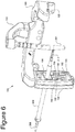
- Figure 1 illustrates an instrument 10, or drill guide assembly, for locating an axis of a blocking screw.
- the instrument 10 is applicable for a retrograde installation of an intramedullary device into a femur or an antegrade installation of an intramedullary device into a tibia.
- the instrument 10 includes a drill jig 11 having a radiolucent frame portion 14 and a mounting portion 12.
- the mounting portion 12 may also be referred to as a drill guide, and the frame portion 14 may also be referred to as a drop.
- the frame portion 14 is made of plastic, a composite material, or other radiolucent material.
- the mounting portion 12 is integral with the frame portion 14.
- the mounting portion 12 and the frame portion 14 may be separate components but capable of being coupled together.
- the mounting portion 12 is adapted to connect to an intramedullary device 204 (best seen in Figure 4 ), such as a trial or a nail, to a reduction tool, or to an awl.
- an intramedullary device 204 such as a trial or a nail
- a barrel 16 is connected to the mounting portion 12, and the barrel 16 connects to the intramedullary device at a first end 17.
- the barrel 16 is hollow, and a fastener (not shown) may be inserted into a fastener hole 50 to secure the intramedullary device to the mounting portion 12.
- the mounting portion 12 also has a neck 13 which extends in a generally perpendicular direction from the frame portion 14.
- the frame portion 14 has a first leg 42 and a second leg 44.
- the second leg 44 extends at an angle relative to the first leg 42.
- a first protrusion 46 extends from the first leg 42
- a second protrusion 48 extends from the second leg 44.
- the second protrusion 48 is parallel to the first protrusion 46.
- the frame portion 14 also has a hole or aperture for locating an axis of a blocking screw.
- the frame portion 14 has a first blocking screw hole 18, a second blocking screw hole 22, a third blocking screw hole 24, a fourth blocking screw hole 25, a fifth blocking screw hole 28, and a sixth blocking screw hole 29. While six blocking screw holes are shown, those skilled in the art would understand that a greater or lesser number of holes may be provided.
- the first blocking screw hole 18 and the second blocking screw hole 22 are located in the first protrusion 46, and the third blocking screw hole 24 and the fourth blocking screw hole 25 are located in the second protrusion 48.
- the fifth blocking screw hole 28 is located in the first leg 42, and the sixth blocking screw hole 29 is located in the second leg 44.
- the frame portion 14 may also include nail targeting holes which may be used to target an axis of a screw for locking the intramedullary device to the bone.
- the frame portion 14 has a first nail targeting hole 20, a second nail targeting hole 23, a third nail targeting hole 26, and a fourth nail targeting hole 27. While four nail targeting holes are shown, those skilled in the art would understand that a greater or lesser number of holes may be provided.
- the first nail targeting hole 20 is located in the first protrusion 46
- the fourth nail targeting hole 27 is located in the second protrusion 48.
- the second nail targeting hole 23 is located in the first leg 42
- the third nail targeting hole 26 is located in the second leg 44.
- the frame portion 14 or the mounting portion 12 may be adjustable in a longitudinal direction relative to the intramedullary device in order to locate the axis of the blocking screw.
- the frame portion 14 or the mounting portion 12 may be adjustable in a longitudinal direction along an imaginary axis of the intramedullary device in order to locate the axis of the blocking screw.
- the barrel 16 may be available in different lengths or extendable to allow for adjustment of the mounting portion 12. If the barrel 16 is available in different lengths, then the barrel can be removed and replaced by a second barrel having a length different than the first barrel. Alternatively, the barrel 16 may be extended or collapsed to move the frame portion 14 relative to the intramedullary device.
- the position of the hole or aperture for locating the axis of the blocking screw relative to the intramedullary device may be adjusted.
- the neck 13 may be available in different lengths or extendable to adjust the relative position of the blocking screw axis.
- the instrument 10 may include a fracture alignment device 30.
- the fracture alignment device 30 is used in conjunction with the frame portion 14 to rotate and/or translate bone fragments.
- there are three fracture alignment devices 31, 32, 34 but those skilled in the art would understand that a greater or lesser number of devices may be used.
- Each fracture alignment device 31, 32, 34 is operatively connected to the drill jig 11.
- each fracture alignment device 31, 32, 34 threadingly engages the drill jig 11.
- the drill jig 11 includes a first mounting hole 36, a second mounting hole 38, and a third mounting hole 40.
- Each fracture alignment device 31, 32, 34 corresponds to the respective mounting hole 36, 38, 40.
- Each fracture alignment device 31, 32, 34 may have a predefined angle relative to the barrel 16, or each fracture alignment device 31, 32, 34 may swivel such that the surgeon may choose an angle relative to the drill jig 11.
- Figures 2-18 depict a second embodiment of the instrument, generally indicated by numeral reference 100.
- the instrument 100 is used to, among other things, locate an axis of a blocking screw 210 relative to an intramedullary device 204, such as a trial or a nail.
- the instrument 100 may also be used to target an axis of a screw used to lock the intramedullary device 204 to a bone.
- the instrument, or drill guide assembly, 100 includes a frame 120, a mount 110, a pilot member 130, and a cartridge 136.
- the instrument 100 may also have a fracture alignment device 140.
- the mount 110 is removably attached to the frame 120.
- the mount 110 and the frame 120 may be integrally formed together.
- the combination may be referred to as a drill jig 105 (best seen in Figure 5 ).
- the mount 110 also may be termed a drill guide or simply a guide
- the frame 120 also may be termed a drop or a base.
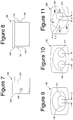
- FIG 3 illustrates the frame 120.
- the frame 120 is made of plastic, a composite material, or other radiolucent material.
- the frame 120 has a first leg 121 and a second leg 123.
- the second leg 123 and the first leg 121 are arcuate and form one continuous curve.
- each leg 121, 123 may include scalloped or cut out portions 128 to provide added clearance and to save weight.
- a first protrusion 125 extends from the first leg 121, and a second protrusion 127 extends from the second leg 123.
- the second protrusion 127 is parallel to the first protrusion 125.
- the frame 120 includes at least one channel 122 for mounting the pilot member 130.
- each protrusion 125, 127 includes a channel 122.
- additional channels 122 may be located on the legs 121, 123 or at the location where the first leg 121 meets the second leg 123.
- the frame 120 includes at least one mounting hole 124 for receiving the fracture alignment device 140.
- the frame 120 includes a third protrusion 150 and a fourth protrusion 152 located at the respective end portion of each leg 121, 123, and each of the third protrusion 150 and the fourth protrusion 152 includes the mounting hole 124.
- the frame 120 may include one or more holes or apertures for locating an axis of a blocking screw.
- the embodiment depicted in Figure 3 includes blocking screw locating holes 126, with one of the blocking screw holes 126 located in each leg 121, 123.
- the frame 120 may also include nail target holes 180 which may be used to target an axis of a screw for locking the intramedullary device to the bone.
- the frame 120 has two nail targeting holes 180. While two nail targeting holes are shown, those skilled in the art would understand that a greater or lesser number of holes may be provided.
- the blocking screw locating holes 126 and the nail target holes 180 may be dimensioned to accept a typical outer drill sleeve 206 (best seen in Figure 6 ).
- the blocking screw locating holes 126 and the nail target holes 180 are about 10.5 millimeters in diameter.
- FIG. 4 illustrates the mount 110.
- the mount 110 is adapted to connect to the intramedullary device 204, such as a trial or a nail, or to a reduction tool.
- a bolt or other fastener 202 may be used to connect the intramedullary device 204 to the mount 110.
- the mount 110 includes a neck portion 117 and a barrel portion 118. In the depicted embodiments, the barrel portion 118 is an integral part of the mount 110, but those skilled in the art would understand that the barrel portion could equally be a separate component.
- the barrel portion 118 connects to the intramedullary device 204 at a first end 119.
- the mount 110 also includes a first pin 112, a second pin 114, and a third pin 116.
- the pins 112, 114, 116 are used to align and connect the mount 110 to the frame 120. While pins are shown in the depicted embodiments, those skilled in the art would understand that other types of connectors or fasteners may be used.
- the mount 110 is made from a rigid material.
- the mount 110 may be made from plastic or any medical grade metal, such as stainless steel, aluminum, or titanium.
- a portion of the mount 110 is metal and another portion is plastic such that at least part of the mount 110 is radiolucent.
- the neck portion 117 may be made from plastic and the barrel portion 118 may be made of metal.
- Figure 5 illustrates the mount 110 and the frame 120.
- the mount 110 is removably attached to the frame 120.
- the assembly of the mount 110 to the frame 120 forms the drill jig 105.
- the frame 120 includes pin holes 154, 156, 158 to receive the respective pins 112, 114, 116.
- a first pin hole 154 corresponds to the first pin 112
- a second pin hole 156 corresponds to the second pin 114
- a third pin hole 158 corresponds to the third pin 116.
- the second pin 114 and the third pin 116 are used to align the mount 110 with the frame 120, and the first pin 112 is a locking pin and a locking mechanism (not shown) captures the first pin 112 when placed in the first pin hole 154.
- the pins 112, 114, 116 of the mount 110 slide within the pin holes 154, 156, 158 until a bottom surface 111 of the mount 110 contacts a top surface 129 of the frame 120. As the bottom surface 111 approaches the top surface 129, the locking mechanism engages to capture the first pin 112.
- the frame 120 may include one or more recess 160.
- the recess 160 is located generally adjacent to where the mount 110 is attached to the frame 120 but other locations may be used.
- the recess 160 provides additional clearance, reduces the overall weight of the frame 120, and, in some cases, provides a hand rest for the surgeon.
- Figure 6 illustrates the pilot member 130, which also may be termed a blocking screw attachment.
- the pilot member 130 is removably attached to the frame 120.
- the pilot member 130 also may be integrally formed as a portion of the frame 120.
- the pilot member 130 is made of plastic, a composite material, or other radiolucent material.
- the pilot member 130 is adapted to receive the cartridge 136.
- the cartridge 136 also may be termed a blocking screw cartridge.
- the cartridge 136 may also be made of plastic, a composite material, or other radiolucent material.
- the cartridge 136 moves or slides in a longitudinal direction parallel to an imaginary long axis of the intramedullary device 204.
- the cartridge 136 includes at least one hole or an aperture for locating an axis of a blocking screw.
- the cartridge has two locating holes 137.
- the embodiment depicted in Figure 11 has only one aperture 337.
- the pilot member 130 has tracks 132, and the cartridge 136 slides along the tracks 132.
- the tracks 132 are formed by guide members 192 spaced apart from a center rib 193.
- the guide members 192 may include openings 196 to allow the cartridge 136 access to the tracks 132.
- the tracks 132 have detents 133.
- the detents 133 are placed at regular intervals along the center rib 193.
- the cartridge 136 has a plunger 138 (best seen in Figures 7 and 8 ) on each side.
- the plungers 138 cooperate with the detents 133 to temporarily fix the cartridge in a location. In this manner, the cartridge 136 is slid along the tracks 132 and temporarily fixed in a position by engagement of each plunger 138 with one of the detents 133.
- the spacing between the detents 133 may be in the order from about 2 millimeters to about ten millimeters. In the embodiment depicted in Figure 6 , the detents 133 have a spacing of about five millimeters between them.
- Figures 7-10 illustrate a first embodiment of the cartridge 136.
- the cartridge 136 includes a lip 139.
- the lip 139 engages the pilot member 130, such as a first planar surface 184 (best seen in Figure 12 ), and limits travel of the cartridge 136 in a direction transverse to the longitudinal direction of the tracks 132.
- the cartridge 136 includes the locating holes 137.
- the locating holes 137 are dimensioned to accept a typical outer drill sleeve 206 (best seen in Figure 6 ). In the embodiments depicted in Figures 9 and 10 , the locating holes are about 10.5 millimeters in diameter.
- the locating holes 137 are separated by a distance.
- the distance between the locating holes is dimensioned based upon the desired effect of the blocking screw. For example, if the blocking screw is used to direct the path of the nail or the fragment, then the hole spacing is selected such that blocking screw is inserted slightly offset from the center of the medullary cavity. Thus, the hole spacing depends upon the width of the medullary cavity. Further, only one of the blocking screw holes may be selected if the blocking screw is used to direct the path of the nail. The particular blocking screw hole is selected based upon the direction to which the nail or the fragment must be directed.
- the hole spacing is selected such that the blocking screws are placed tangentially to the intramedullary nail. In this case, the hole spacing depends upon the diameter of the intramedullary nail.
- the center axis of each locating hole 137 is separated by a length L1.
- the center axis of each locating hole is separated by a length L2.
- the center axis of each locating hole 137 may be separated by a length L, wherein the length L may range from about five millimeters to about twenty-five millimeters.
- the length L1 is about five millimeters
- the length L2 is about eighteen millimeters.
- the spacing between holes 137 may be defined in terms of the nail size.
- the spacing between an edge of each hole 137 may be defined in terms of the intramedullary nail diameter.
- the spacing may be defined in terms of the proximal diameter, the distal diameter, or the diameter of the main body shaft.
- the spacing would also be about thirteen millimeters or slightly larger. The spacing may be slightly larger to allow for tolerances in the nail, tolerances in the blocking screws, dimensional errors, or to allow the nail to translate slightly.
- each modular cartridge has a spacing between the edges of each hole that corresponds to a common nail size (i.e., about 8.5 millimeters, about 10 millimeters, about 12 millimeters, and about 13 millimeters or slightly larger).
- FIG 11 illustrates a second embodiment of the cartridge, generally indicated by reference numeral 300.
- the cartridge 300 has a rotating drum 310 and the locating hole 337.
- the rotating drum 310 may also include a handle 312.
- the rotating drum 310 has a center 314.
- the locating hole 337 is offset from the center 314 a fixed distance D.
- the distance D may be in the range from about one millimeter to about fifteen millimeters. In the embodiment depicted in Figure 11 , the distance D is about six millimeters.
- the rotating drum 310 allows a single cartridge to have multiple locations for the hole 337. The user rotates the rotating drum 310 using the handle 312 until the locating hole 337 reaches a selected location.
- the rotating drum 310 may be rotated clockwise or counter-clockwise.
- the cartridge 300 may include markings M1, M2, M3, M4.
- the markings M1, M2, M3, M4 may specify the horizontal distance (relative to Figure 11 ) from the center 314 to the center of the locating hole 337.
- the markings M1, M2, M3, M4 may specify the horizontal distance (relative to Figure 11 ) from the center 314 to the edge of the locating hole 337.
- Figures 12 and 13 illustrate a first embodiment of the pilot member 130.
- the first embodiment may be used for a retrograde installation of a femoral intramedullary device.
- the pilot member 130 has an inner portion 173 and an outer portion 174.
- the inner and outer portion 173, 174 are formed by walls 175, 176, 177, 178.
- the pilot member 130 has a first wall 175, a second wall 176, a third wall 177, and a fourth wall 178.
- the second wall 175 is substantially parallel to the first wall 175.
- the outer portion 174 of the first wall 175 and the second wall 176 is arcuate.
- the third wall 177 and the fourth wall 178 are substantially parallel to each other and substantially transverse to the first wall 175 and the second wall 176.
- the tracks 132 are located on the inner portion 173 along the first wall 175 and the second wall 176.
- the guide members 192 may include openings 196 to allow the cartridge 136 access to the tracks 132.
- the pilot member 130 also includes a first outer face 182 and the first planar surface 184.
- the first planar surface 184 is offset from the first outer face 182. This offset provides a ridge for the lip 139 of the cartridge 136. In other words, the lip 139 contacts first planar surface 184 and slides on this surface.
- the pilot member 130 also may include a second outer face 186 and a second planar surface 188. In some embodiments, the pilot member 130 may be mirrored about a center line 190 such that the pilot member 130 is reversible.
- the pilot member 130 also includes a first stud 134.
- the first stud 134 is located on the outer portion 174 of the third wall 177.
- the first stud 134 is adapted to mate with the channel 122 of the frame 120.
- the pilot member 130 may also include a second stud 135 located on the outer portion 174 of the fourth wall 178.
- the second stud 135 may be the same size and shape as the first stud 134 such that the pilot member 130 is reversible.
- the second stud 135 may have a different size and/or shape relative to the first stud 134.
- Figures 14 and 15 illustrate a second embodiment of the pilot member 130'.
- the pilot member 130' may be used for an antegrade installation of a tibial intramedullary device.
- the pilot member 130' has an inner portion 173', an outer portion 174', a first wall 175', a second wall 176', a third wall 177', a fourth wall 178', a first outer face 182', and a first planar surface 184'.
- the second embodiment is similar to the first embodiment except the third wall 177' and the fourth wall 178' are angled to accommodate the relative angle of the tibial intramedullary device.
- the pilot member 130' also includes a first stud 134' and a second stud 135'.
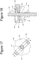
- FIG 16 illustrates a detailed view of the fracture alignment device 140.
- the fracture alignment device 140 includes a housing 142 and a screw shaft 144.
- the housing 142 includes an extension member 146 which threadingly engages the frame 120, such as by threading into the mounting hole 124.
- the housing 142 also includes grip portions 148.
- the screw shaft 144 has a threaded portion 145 and a tip 147.
- the threaded portion 145 may have a diameter of about 6.4 millimeters.
- the tip 147 has a hexagonal shape but other shapes may be used.
- the tip 147 is adapted for connection with a tool (not shown) such that a surgeon may use the tool to rotate the tip 147.
- the threaded portion 145 threads into a threaded hole 170 (best seen in Figures 17 and 18 ). As such, the screw shaft 144 moves axially when rotated.
- FIGs 17 and 18 illustrate in greater detail the fracture alignment device 140.
- the fracture alignment device 140 includes buttons 166. As best seen in Figure 17 , the buttons 166 overlap and cooperate together. Each button 166 has a threaded hole 170 and a clearance hole 172. Springs 168 separate the buttons 166 and apply a spring force to bias each button 166 radially outward towards the housing 142. Each button has a slot or groove 163, and the housing 142 includes pin holes 164. A locking pin 162 is placed in the pin hole 164 and extends into the slot 163, thereby limiting the movement of each respective button 166. In a first position, the threaded holes 170 engage the threaded portion 145 of the screw shaft 144 of the fracture alignment device 140.
- buttons 166 move to a second position.
- the threaded holes 170 disengage from the screw shaft 144 and the clearance holes 172 are proximate the screw shaft 144 such that the screw shaft 144 can easily be moved relative to the buttons 166.
- a surgeon can push the buttons 166 for gross movement of the screw shaft 144 and then release the buttons 166 and rotate the screw shaft 144 within the threaded holes 170 for fine adjustment of the screw shaft 144.
- a first step is to ream the proximal tibia fragment or distal femur fragment.
- a second step is to select the appropriate barrel 16. This is accomplished by estimating a length required for the barrel 16 and selecting a barrel with that length.
- a third step is to connect the instrument 10 to the intramedullary device 204 or a reduction tool. This step is achieved by attaching the barrel 16 of the mounting portion 12 to the intramedullary device 204. This may be done by engaging the fastener 202 with the barrel 16 and connecting the fastener 202 with the intramedullary device 204. The intramedullary device 204 is then inserted into the medullary cavity, if it has not been done already.
- the user may use the fracture alignment device 30 to manipulate the fragment by rotating the fracture alignment devices 31, 32, 34.
- the next step is to select an aperture 18, 22, 24, 25, 28, 29 for placement of the blocking screw 210.
- a location for the blocking screw 210 is selected through the surgeon's skill and judgment.
- the aperture 18, 22, 24, 25, 28, 29 is selected by choosing the aperture closest to the preferred location of the blocking screw 210.
- the next step is to install an outer drill sleeve 206 into the aperture 18, 22, 24, 25, 28, 29. Thereafter, the location of the aperture 18, 22, 24, 25, 28, 29 is verified through the use of an x-ray machine or image enhancer.
- the aperture 18, 22, 24, 25, 28, 29 is not in the correct location, it may be necessary to adjust the instrument 10 by rotating the drill jig 11 relative to the intramedullary device 204 or by replacing the barrel 16 with a barrel having a different length. In other words, it may be necessary to replace the barrel 16 with one longer or shorter. If the barrel 16 has been changed or the drill jig 11 has been rotated, it will be necessary to repeat the verification step.
- the blocking screw pilot hole is drilled.
- a drill (not shown) is installed in the outer drill sleeve 206 and the bone is drilled. After the bone is drilled, the bone may be tapped. Next, the blocking screw is installed. The blocking screw 210 is attached to the end of a blocking screw wrench 208 (best seen in Figure 6 ) and the blocking screw is screwed into the bone. This process may be repeated for the installation of additional blocking screws.
- the outer drill sleeve 206 is removed, and the instrument 10 is dismounted from the intramedullary device 204.
- the trial would be removed with the instrument 10, and the instrument 10 may be used to insert the intramedullary nail into the reamed hole. Finally, the intramedullary nail is locked into place.
- the instrument 10 may include holes for targeting the interlocking screws, and the instrument 10 is used to place the locking screws into the intramedullary nail.
- a first step is to connect the mount 110 to the intramedullary nail 204. This may be done by engaging the fastener 202 with the barrel portion 118 and connecting the fastener 202 with the intramedullary device 204.
- the frame 120 is releasably attached to the mount 110. In general, this is done after the mount 110 is attached to the intramedullary device 204, but the frame 120 equally could be attached to the mount 110 before connection to the intramedullary device 204.
- the cartridge 136, 300 is temporarily attached to the pilot member 130, and the pilot member 130 is temporarily attached to the frame 120. The order of these steps is not critical.
- the cartridge 136, 300 may be attached either before or after the pilot member 130 is attached to the frame 120.
- the pilot member 130 may be attached to the frame 120 either before or after the frame 120 is attached to the mount 110.
- the cartridge 136, 300 is attached to the pilot member by inserting the posts 131 into the openings 196 and sliding the posts 131 in the tracks 132 until the plungers 138 engages detents 133.
- a location for the blocking screw 210 is selected through the surgeon's skill and judgment.
- the aperture 126, 137, 337 is selected by choosing the aperture closest to the preferred location of the blocking screw 210. If the cartridge aperture 137, 337 is selected, the cartridge 136 is slid along the pilot member 130 until the aperture 137, 337 reaches the preselected location of the blocking screw 210.
- the user may use the fracture alignment device 140 to manipulate the fragment.
- the user mounts the fracture alignment device 140 to the frame 120 by inserting the extension member 146 into one of the mounting holes 124. Thereafter, the user manipulates the fragment by rotating the screw shaft 144.
- an outer drill sleeve 206 is inserted into the aperture 126, 137, 337. Thereafter, the location of the aperture 126, 137, 337 is verified through the use of an x-ray machine or image enhancer. If the aperture 126, 137, 337 is not in the correct location, it may be necessary to adjust the instrument 10 by rotating the frame 120 relative to the intramedullary device 204 or by sliding the cartridge 136, 300 relative to the pilot member 130. If adjustment was necessary, the verification step must be repeated. Once the outer drill sleeve 206 is in the correct location, the blocking screw pilot hole is drilled. A drill (not shown) is installed in the outer drill sleeve 206 and the bone is drilled.
- the bone may be tapped.
- the blocking screw is installed.
- the blocking screw 210 is attached to the end of a blocking screw wrench 208 (best seen in Figure 6 ) and the blocking screw is screwed into the bone. This process may be repeated for the installation of additional blocking screws.
- the outer drill sleeve is removed, and the instrument 100 is dismounted from the intramedullary device 204.
Landscapes
- Health & Medical Sciences (AREA)
- Surgery (AREA)
- Life Sciences & Earth Sciences (AREA)
- Orthopedic Medicine & Surgery (AREA)
- Heart & Thoracic Surgery (AREA)
- Veterinary Medicine (AREA)
- Engineering & Computer Science (AREA)
- Biomedical Technology (AREA)
- Nuclear Medicine, Radiotherapy & Molecular Imaging (AREA)
- Medical Informatics (AREA)
- Molecular Biology (AREA)
- Animal Behavior & Ethology (AREA)
- General Health & Medical Sciences (AREA)
- Public Health (AREA)
- Dentistry (AREA)
- Oral & Maxillofacial Surgery (AREA)
- Neurology (AREA)
- Surgical Instruments (AREA)
Applications Claiming Priority (3)
| Application Number | Priority Date | Filing Date | Title |
|---|---|---|---|
| US65510005P | 2005-02-22 | 2005-02-22 | |
| EP06735721.0A EP1850763B1 (fr) | 2005-02-22 | 2006-02-22 | Instrument pour diriger des vis de blocage |
| PCT/US2006/006178 WO2006091625A2 (fr) | 2005-02-22 | 2006-02-22 | Instrument pour diriger des vis de blocage |
Related Parent Applications (1)
| Application Number | Title | Priority Date | Filing Date |
|---|---|---|---|
| EP06735721.0A Division EP1850763B1 (fr) | 2005-02-22 | 2006-02-22 | Instrument pour diriger des vis de blocage |
Publications (2)
| Publication Number | Publication Date |
|---|---|
| EP3165182A1 true EP3165182A1 (fr) | 2017-05-10 |
| EP3165182B1 EP3165182B1 (fr) | 2022-05-11 |
Family
ID=36588792
Family Applications (2)
| Application Number | Title | Priority Date | Filing Date |
|---|---|---|---|
| EP06735721.0A Not-in-force EP1850763B1 (fr) | 2005-02-22 | 2006-02-22 | Instrument pour diriger des vis de blocage |
| EP16187481.3A Active EP3165182B1 (fr) | 2005-02-22 | 2006-02-22 | Instrument pour diriger des vis de blocage |
Family Applications Before (1)
| Application Number | Title | Priority Date | Filing Date |
|---|---|---|---|
| EP06735721.0A Not-in-force EP1850763B1 (fr) | 2005-02-22 | 2006-02-22 | Instrument pour diriger des vis de blocage |
Country Status (7)
| Country | Link |
|---|---|
| US (3) | US8257361B2 (fr) |
| EP (2) | EP1850763B1 (fr) |
| JP (1) | JP2008531088A (fr) |
| AU (1) | AU2006216759B2 (fr) |
| CA (1) | CA2598679C (fr) |
| ES (1) | ES2606064T3 (fr) |
| WO (1) | WO2006091625A2 (fr) |
Families Citing this family (33)
| Publication number | Priority date | Publication date | Assignee | Title |
|---|---|---|---|---|
| BRPI0813156A2 (pt) | 2007-06-22 | 2014-12-23 | Anthem Orthopaedics Van Llc | Haste intramedular com prendedor pivotante e método para uso da mesma |
| US8771283B2 (en) * | 2007-12-17 | 2014-07-08 | Wright Medical Technology, Inc. | Guide assembly for intramedullary fixation and method of using the same |
| US8152807B2 (en) * | 2008-03-31 | 2012-04-10 | Olecranail Llc | Intramedullary device assembly and associated method |
| US8303600B2 (en) * | 2008-06-30 | 2012-11-06 | Biomet C.V. | Targeting apparatus for use in a medical procedure |
| US8216237B2 (en) * | 2009-06-04 | 2012-07-10 | Edwards Scott G | Intramedullary device assembly and associated method |
| GB0918006D0 (en) * | 2009-10-14 | 2009-12-02 | Chana Gursharan S | Improvements in or relating to the removal of articles embedded in surrounding material |
| EP2488112B1 (fr) * | 2009-10-15 | 2017-08-30 | Synthes GmbH | Dispositif de retenue de manchon de protection |
| WO2012103354A1 (fr) * | 2011-01-26 | 2012-08-02 | Del Palma Orthopedics, LLC | Dispositifs de fusion d'extrémité supérieure |
| US9622759B2 (en) * | 2011-04-21 | 2017-04-18 | DePuy Synthes Products, Inc. | Spline oriented indexing guide |
| US8968324B2 (en) | 2011-10-27 | 2015-03-03 | Kettering University | Adjustable jig and method for targeting interlocking holes of an intramedullary nail |
| WO2013102025A1 (fr) | 2011-12-29 | 2013-07-04 | Synthes Usa, Llc | Système, kit et procédé d'insertion suprapatellaire |
| JP6247644B2 (ja) * | 2012-02-08 | 2017-12-13 | エピックス オーソペディックス インコーポレイテッド | 連続調節可能ターゲッティングアセンブリを有するインプラント挿入デバイス |
| US9668791B2 (en) * | 2012-04-04 | 2017-06-06 | Kok Sun Khong | Surgical implant device, method and apparatus for implanting thereof |
| US9138278B2 (en) | 2012-05-04 | 2015-09-22 | Zimmer, Inc. | Suprapatellar system and method |
| US9155582B2 (en) | 2013-01-30 | 2015-10-13 | DePuy Synthes Products, Inc. | Aiming instrument |
| WO2016008849A1 (fr) * | 2014-07-15 | 2016-01-21 | Ot Medizintechnik Gmbh | Dispositif de positionnement pour fixer un clou intramédullaire dans un os long |
| US11617609B2 (en) | 2015-07-08 | 2023-04-04 | Arizona Board Of Regents On Behalf Of The University Of Arizona | Percutaneous methods, systems, and devices for positioning a guide wire in a bone |
| US10646695B1 (en) * | 2015-07-08 | 2020-05-12 | Arizona Board Of Regents On Behalf Of The University Of Arizona | Percutaneous methods, systems, and devices for positioning a guide wire in a bone |
| USD797825S1 (en) * | 2015-10-05 | 2017-09-19 | Wolter Corp. | Metal stamp jig |
| ITUA20163613A1 (it) * | 2016-05-19 | 2017-11-19 | Orthofix Srl | Strumentario perfezionato per l'allineamento di viti di fissaggio da inserire in fori trasversali di chiodi per ossa lunghe, in particolare chiodi midollari |
| US10751096B2 (en) | 2016-09-22 | 2020-08-25 | Bala Sundararajan | Systems and methods for intramedullary nail implantation |
| US11083503B2 (en) | 2016-09-22 | 2021-08-10 | Globus Medical, Inc. | Systems and methods for intramedullary nail implantation |
| US10299847B2 (en) * | 2016-09-22 | 2019-05-28 | Globus Medical, Inc. | Systems and methods for intramedullary nail implantation |
| US11426220B2 (en) | 2017-10-11 | 2022-08-30 | Howmedica Osteonics Corp. | Humeral fixation plate guides |
| US10610274B2 (en) * | 2018-02-27 | 2020-04-07 | Jonathan P. GARINO | Instrument for fracture alignment and plate compression |
| JP6983204B2 (ja) * | 2018-10-08 | 2021-12-17 | グローバス メディカル インコーポレイティッド | 髄内釘埋め込みのためのシステムおよび方法 |
| US11000327B2 (en) * | 2018-12-14 | 2021-05-11 | Nextremity Solutions, Inc. | Bone defect repair apparatus and method |
| US10987146B2 (en) | 2019-03-05 | 2021-04-27 | Nextremity Solutions, Inc. | Bone defect repair apparatus and method |
| CN110393573B (zh) * | 2019-08-12 | 2022-09-27 | 西北工业大学 | 一种用于骨科手术的钉孔修正器 |
| US11207115B2 (en) * | 2019-11-21 | 2021-12-28 | DePuy Synthes Products, LLC | System and method of coupling an alignment guide to an intramedullary nail insertion handle |
| US11751887B2 (en) * | 2019-12-18 | 2023-09-12 | DePuy Synthes Products, Inc. | Interoperative aiming arm |
| CN111991071B (zh) * | 2020-08-26 | 2021-07-13 | 中国科学院大学宁波华美医院 | 一种股骨颈空心钉导向装置 |
| EP4215131A1 (fr) * | 2022-01-19 | 2023-07-26 | Globus Medical, Inc. | Systèmes d'implantation de clou intramédullaire |
Citations (7)
| Publication number | Priority date | Publication date | Assignee | Title |
|---|---|---|---|---|
| EP0514662A1 (fr) * | 1991-05-24 | 1992-11-25 | Synthes AG, Chur | Instrument chirurgical pour positionner des éléments de fixation d'ostéosynthèse en particulier les vis osseuses |
| DE4238582A1 (de) * | 1992-11-16 | 1994-05-19 | Erwin Prof Dr Med Brug | Distales Zielgerät bei Verriegelungsnagelungen |
| US6514253B1 (en) * | 2000-11-22 | 2003-02-04 | Meei-Huei Yao | Apparatus for locating interlocking intramedullary nails |
| EP1329197A1 (fr) * | 2002-01-14 | 2003-07-23 | HIT MEDICA S.r.L. | Outil servant à trouver la position des trous destinés aux vis de fixation de clous intramédullaires |
| EP1356777A2 (fr) * | 2002-04-15 | 2003-10-29 | HIT MEDICA S.r.L. | Guide de vissage pour clou intramedullaire |
| WO2003105659A2 (fr) * | 2002-06-17 | 2003-12-24 | Mazor Surgical Technologies Ltd. | Robot concu pour etre utilise avec des pieces orthopediques |
| US20030236527A1 (en) * | 2000-07-21 | 2003-12-25 | Fujio Kawakami | Multi-slot guide for bone-setting operation for a femoral neck fracture |
Family Cites Families (16)
| Publication number | Priority date | Publication date | Assignee | Title |
|---|---|---|---|---|
| EP0187283B1 (fr) * | 1984-12-26 | 1989-04-26 | Nivarox-FAR S.A. | Appareil pour repérer in situ les trous transversaux d'une broche creuse implantée dans le canal médullaire, pour la contention des fragments d'un os fracturé |
| US4667664A (en) * | 1985-01-18 | 1987-05-26 | Richards Medical Company | Blind hole targeting device for orthopedic surgery |
| FR2634641A1 (fr) * | 1988-07-28 | 1990-02-02 | Michel Jean Pierre | Dispositif de visee pour le positionnement d'au moins un organe de fixation a travers un implant, du type clou centro-medullaire |
| US5429640A (en) * | 1992-11-27 | 1995-07-04 | Clemson University | Intramedullary rod for fracture fixation of femoral shaft independent of ipsilateral femoral neck fracture fixation |
| US5474561A (en) * | 1994-02-01 | 1995-12-12 | Yao; Meei-Huei | All positional and universal guiding device for interlocking intramedullary nail |
| US5549610A (en) * | 1994-10-31 | 1996-08-27 | Smith & Nephew Richards Inc. | Femoral intramedullary nail |
| DE29608071U1 (de) * | 1996-05-04 | 1997-09-04 | Synthes Ag | Zielgerät zur Verriegelung der Fusspartie von Marknägeln |
| IT1293934B1 (it) * | 1997-01-21 | 1999-03-11 | Orthofix Srl | Chiodo endomidollare per il trattamento delle fratture dell'anca |
| US6036696A (en) * | 1997-12-19 | 2000-03-14 | Stryker Technologies Corporation | Guide-pin placement device and method of use |
| US6494913B1 (en) * | 1998-03-17 | 2002-12-17 | Acumed, Inc. | Shoulder prosthesis |
| DE19819168C1 (de) * | 1998-04-24 | 2000-01-20 | Aap Implantate Ag | Zielgerät zur röntgenfreien proximalen und distalen Verriegelung von Marknägeln |
| EP1205150B1 (fr) * | 2000-11-13 | 2007-04-04 | Benoist Girard Sas | Appareil-cible pour ostéotomie endofémorale |
| US7175633B2 (en) * | 2001-10-17 | 2007-02-13 | Synthes (Usa) | Orthopedic implant insertion instruments |
| US7056322B2 (en) * | 2002-03-28 | 2006-06-06 | Depuy Orthopaedics, Inc. | Bone fastener targeting and compression/distraction device for an intramedullary nail and method of use |
| US7505838B2 (en) * | 2004-07-09 | 2009-03-17 | Carfax, Inc. | System and method for determining vehicle odometer rollback |
| SG157353A1 (en) | 2005-04-05 | 2009-12-29 | Orthopaedic Int Inc | Intramedullary nail distal targeting device |
-
2006
- 2006-02-22 ES ES06735721.0T patent/ES2606064T3/es active Active
- 2006-02-22 CA CA2598679A patent/CA2598679C/fr not_active Expired - Fee Related
- 2006-02-22 EP EP06735721.0A patent/EP1850763B1/fr not_active Not-in-force
- 2006-02-22 WO PCT/US2006/006178 patent/WO2006091625A2/fr active Application Filing
- 2006-02-22 JP JP2007556410A patent/JP2008531088A/ja active Pending
- 2006-02-22 EP EP16187481.3A patent/EP3165182B1/fr active Active
- 2006-02-22 US US11/816,909 patent/US8257361B2/en active Active
- 2006-02-22 AU AU2006216759A patent/AU2006216759B2/en not_active Ceased
-
2012
- 2012-07-31 US US13/562,944 patent/US9301767B2/en active Active
-
2016
- 2016-02-23 US US15/051,054 patent/US20160166264A1/en not_active Abandoned
Patent Citations (7)
| Publication number | Priority date | Publication date | Assignee | Title |
|---|---|---|---|---|
| EP0514662A1 (fr) * | 1991-05-24 | 1992-11-25 | Synthes AG, Chur | Instrument chirurgical pour positionner des éléments de fixation d'ostéosynthèse en particulier les vis osseuses |
| DE4238582A1 (de) * | 1992-11-16 | 1994-05-19 | Erwin Prof Dr Med Brug | Distales Zielgerät bei Verriegelungsnagelungen |
| US20030236527A1 (en) * | 2000-07-21 | 2003-12-25 | Fujio Kawakami | Multi-slot guide for bone-setting operation for a femoral neck fracture |
| US6514253B1 (en) * | 2000-11-22 | 2003-02-04 | Meei-Huei Yao | Apparatus for locating interlocking intramedullary nails |
| EP1329197A1 (fr) * | 2002-01-14 | 2003-07-23 | HIT MEDICA S.r.L. | Outil servant à trouver la position des trous destinés aux vis de fixation de clous intramédullaires |
| EP1356777A2 (fr) * | 2002-04-15 | 2003-10-29 | HIT MEDICA S.r.L. | Guide de vissage pour clou intramedullaire |
| WO2003105659A2 (fr) * | 2002-06-17 | 2003-12-24 | Mazor Surgical Technologies Ltd. | Robot concu pour etre utilise avec des pieces orthopediques |
Also Published As
| Publication number | Publication date |
|---|---|
| CA2598679C (fr) | 2014-09-16 |
| EP3165182B1 (fr) | 2022-05-11 |
| US20160166264A1 (en) | 2016-06-16 |
| AU2006216759A1 (en) | 2006-08-31 |
| AU2006216759B2 (en) | 2011-11-17 |
| US9301767B2 (en) | 2016-04-05 |
| WO2006091625A2 (fr) | 2006-08-31 |
| ES2606064T3 (es) | 2017-03-17 |
| US20130006258A1 (en) | 2013-01-03 |
| CA2598679A1 (fr) | 2006-08-31 |
| EP1850763A2 (fr) | 2007-11-07 |
| US20080264109A1 (en) | 2008-10-30 |
| WO2006091625A3 (fr) | 2006-10-12 |
| US8257361B2 (en) | 2012-09-04 |
| JP2008531088A (ja) | 2008-08-14 |
| EP1850763B1 (fr) | 2016-09-07 |
Similar Documents
| Publication | Publication Date | Title |
|---|---|---|
| US8257361B2 (en) | Instrument for fracture fragment alignment and stabilization | |
| US10092306B2 (en) | Instruments for minimally invasive surgery total knee arthroplasty | |
| US6214013B1 (en) | Method of using a guide-pin placement device | |
| EP2967697B1 (fr) | Système de remplacement de cheville | |
| US10201358B2 (en) | Articulating syndesmosis targeting guide device and method | |
| US7621920B2 (en) | Adjustable cut guide | |
| EP2072016B1 (fr) | Instrument pour plaque osseuse et procédé | |
| US8702714B2 (en) | Instruments for total knee arthroplasty | |
| CA2622379C (fr) | Manche d'insertion et guide de visee pour implant orthopedique | |
| AU2004258937A1 (en) | Plating system with multiple function drill guide | |
| WO2010002589A1 (fr) | Appareil de ciblage pour utilisation dans une procédure médicale | |
| US8043294B2 (en) | Reference mark adjustment mechanism for a femoral caliper and method of using the same | |
| US20070186738A1 (en) | Tibial cut guide assembly having rotatable cut guide body | |
| US20210015500A1 (en) | System and method for placing fasteners into intramedullary nails | |
| US20230310012A1 (en) | Modular guide system for surgical procedures | |
| US20230389860A1 (en) | Flexion/extension surgical guides and methods of using the same | |
| AU2020344499A1 (en) | Implant guides, devices, systems, and methods of use | |
| US10271857B2 (en) | Surgical instrument | |
| WO2023203456A1 (fr) | Clou intramédullaire fémoral rétrograde ainsi que systèmes et méthodes associés | |
| WO2018064779A1 (fr) | Ensemble implant d'ostéosynthèse modulaire |
Legal Events
| Date | Code | Title | Description |
|---|---|---|---|
| PUAI | Public reference made under article 153(3) epc to a published international application that has entered the european phase |
Free format text: ORIGINAL CODE: 0009012 |
|
| STAA | Information on the status of an ep patent application or granted ep patent |
Free format text: STATUS: THE APPLICATION HAS BEEN PUBLISHED |
|
| AC | Divisional application: reference to earlier application |
Ref document number: 1850763 Country of ref document: EP Kind code of ref document: P |
|
| AK | Designated contracting states |
Kind code of ref document: A1 Designated state(s): AT BE BG CH CY CZ DE DK EE ES FI FR GB GR HU IE IS IT LI LT LU LV MC NL PL PT RO SE SI SK TR |
|
| STAA | Information on the status of an ep patent application or granted ep patent |
Free format text: STATUS: REQUEST FOR EXAMINATION WAS MADE |
|
| 17P | Request for examination filed |
Effective date: 20171110 |
|
| RBV | Designated contracting states (corrected) |
Designated state(s): AT BE BG CH CY CZ DE DK EE ES FI FR GB GR HU IE IS IT LI LT LU LV MC NL PL PT RO SE SI SK TR |
|
| STAA | Information on the status of an ep patent application or granted ep patent |
Free format text: STATUS: EXAMINATION IS IN PROGRESS |
|
| STAA | Information on the status of an ep patent application or granted ep patent |
Free format text: STATUS: EXAMINATION IS IN PROGRESS |
|
| 17Q | First examination report despatched |
Effective date: 20201116 |
|
| GRAP | Despatch of communication of intention to grant a patent |
Free format text: ORIGINAL CODE: EPIDOSNIGR1 |
|
| STAA | Information on the status of an ep patent application or granted ep patent |
Free format text: STATUS: GRANT OF PATENT IS INTENDED |
|
| INTG | Intention to grant announced |
Effective date: 20211203 |
|
| RAP3 | Party data changed (applicant data changed or rights of an application transferred) |
Owner name: SMITH & NEPHEW, INC. |
|
| GRAS | Grant fee paid |
Free format text: ORIGINAL CODE: EPIDOSNIGR3 |
|
| GRAA | (expected) grant |
Free format text: ORIGINAL CODE: 0009210 |
|
| STAA | Information on the status of an ep patent application or granted ep patent |
Free format text: STATUS: THE PATENT HAS BEEN GRANTED |
|
| AC | Divisional application: reference to earlier application |
Ref document number: 1850763 Country of ref document: EP Kind code of ref document: P |
|
| AK | Designated contracting states |
Kind code of ref document: B1 Designated state(s): AT BE BG CH CY CZ DE DK EE ES FI FR GB GR HU IE IS IT LI LT LU LV MC NL PL PT RO SE SI SK TR |
|
| REG | Reference to a national code |
Ref country code: GB Ref legal event code: FG4D |
|
| REG | Reference to a national code |
Ref country code: CH Ref legal event code: EP |
|
| REG | Reference to a national code |
Ref country code: AT Ref legal event code: REF Ref document number: 1490735 Country of ref document: AT Kind code of ref document: T Effective date: 20220515 |
|
| REG | Reference to a national code |
Ref country code: DE Ref legal event code: R096 Ref document number: 602006060334 Country of ref document: DE |
|
| REG | Reference to a national code |
Ref country code: IE Ref legal event code: FG4D |
|
| REG | Reference to a national code |
Ref country code: LT Ref legal event code: MG9D |
|
| REG | Reference to a national code |
Ref country code: NL Ref legal event code: MP Effective date: 20220511 |
|
| REG | Reference to a national code |
Ref country code: AT Ref legal event code: MK05 Ref document number: 1490735 Country of ref document: AT Kind code of ref document: T Effective date: 20220511 |
|
| PG25 | Lapsed in a contracting state [announced via postgrant information from national office to epo] |
Ref country code: SE Free format text: LAPSE BECAUSE OF FAILURE TO SUBMIT A TRANSLATION OF THE DESCRIPTION OR TO PAY THE FEE WITHIN THE PRESCRIBED TIME-LIMIT Effective date: 20220511 Ref country code: PT Free format text: LAPSE BECAUSE OF FAILURE TO SUBMIT A TRANSLATION OF THE DESCRIPTION OR TO PAY THE FEE WITHIN THE PRESCRIBED TIME-LIMIT Effective date: 20220912 Ref country code: NL Free format text: LAPSE BECAUSE OF FAILURE TO SUBMIT A TRANSLATION OF THE DESCRIPTION OR TO PAY THE FEE WITHIN THE PRESCRIBED TIME-LIMIT Effective date: 20220511 Ref country code: LT Free format text: LAPSE BECAUSE OF FAILURE TO SUBMIT A TRANSLATION OF THE DESCRIPTION OR TO PAY THE FEE WITHIN THE PRESCRIBED TIME-LIMIT Effective date: 20220511 Ref country code: GR Free format text: LAPSE BECAUSE OF FAILURE TO SUBMIT A TRANSLATION OF THE DESCRIPTION OR TO PAY THE FEE WITHIN THE PRESCRIBED TIME-LIMIT Effective date: 20220812 Ref country code: FI Free format text: LAPSE BECAUSE OF FAILURE TO SUBMIT A TRANSLATION OF THE DESCRIPTION OR TO PAY THE FEE WITHIN THE PRESCRIBED TIME-LIMIT Effective date: 20220511 Ref country code: ES Free format text: LAPSE BECAUSE OF FAILURE TO SUBMIT A TRANSLATION OF THE DESCRIPTION OR TO PAY THE FEE WITHIN THE PRESCRIBED TIME-LIMIT Effective date: 20220511 Ref country code: BG Free format text: LAPSE BECAUSE OF FAILURE TO SUBMIT A TRANSLATION OF THE DESCRIPTION OR TO PAY THE FEE WITHIN THE PRESCRIBED TIME-LIMIT Effective date: 20220811 Ref country code: AT Free format text: LAPSE BECAUSE OF FAILURE TO SUBMIT A TRANSLATION OF THE DESCRIPTION OR TO PAY THE FEE WITHIN THE PRESCRIBED TIME-LIMIT Effective date: 20220511 |
|
| PG25 | Lapsed in a contracting state [announced via postgrant information from national office to epo] |
Ref country code: PL Free format text: LAPSE BECAUSE OF FAILURE TO SUBMIT A TRANSLATION OF THE DESCRIPTION OR TO PAY THE FEE WITHIN THE PRESCRIBED TIME-LIMIT Effective date: 20220511 Ref country code: LV Free format text: LAPSE BECAUSE OF FAILURE TO SUBMIT A TRANSLATION OF THE DESCRIPTION OR TO PAY THE FEE WITHIN THE PRESCRIBED TIME-LIMIT Effective date: 20220511 Ref country code: IS Free format text: LAPSE BECAUSE OF FAILURE TO SUBMIT A TRANSLATION OF THE DESCRIPTION OR TO PAY THE FEE WITHIN THE PRESCRIBED TIME-LIMIT Effective date: 20220911 |
|
| PG25 | Lapsed in a contracting state [announced via postgrant information from national office to epo] |
Ref country code: SK Free format text: LAPSE BECAUSE OF FAILURE TO SUBMIT A TRANSLATION OF THE DESCRIPTION OR TO PAY THE FEE WITHIN THE PRESCRIBED TIME-LIMIT Effective date: 20220511 Ref country code: RO Free format text: LAPSE BECAUSE OF FAILURE TO SUBMIT A TRANSLATION OF THE DESCRIPTION OR TO PAY THE FEE WITHIN THE PRESCRIBED TIME-LIMIT Effective date: 20220511 Ref country code: EE Free format text: LAPSE BECAUSE OF FAILURE TO SUBMIT A TRANSLATION OF THE DESCRIPTION OR TO PAY THE FEE WITHIN THE PRESCRIBED TIME-LIMIT Effective date: 20220511 Ref country code: DK Free format text: LAPSE BECAUSE OF FAILURE TO SUBMIT A TRANSLATION OF THE DESCRIPTION OR TO PAY THE FEE WITHIN THE PRESCRIBED TIME-LIMIT Effective date: 20220511 Ref country code: CZ Free format text: LAPSE BECAUSE OF FAILURE TO SUBMIT A TRANSLATION OF THE DESCRIPTION OR TO PAY THE FEE WITHIN THE PRESCRIBED TIME-LIMIT Effective date: 20220511 |
|
| REG | Reference to a national code |
Ref country code: DE Ref legal event code: R097 Ref document number: 602006060334 Country of ref document: DE |
|
| PLBE | No opposition filed within time limit |
Free format text: ORIGINAL CODE: 0009261 |
|
| STAA | Information on the status of an ep patent application or granted ep patent |
Free format text: STATUS: NO OPPOSITION FILED WITHIN TIME LIMIT |
|
| 26N | No opposition filed |
Effective date: 20230214 |
|
| PG25 | Lapsed in a contracting state [announced via postgrant information from national office to epo] |
Ref country code: SI Free format text: LAPSE BECAUSE OF FAILURE TO SUBMIT A TRANSLATION OF THE DESCRIPTION OR TO PAY THE FEE WITHIN THE PRESCRIBED TIME-LIMIT Effective date: 20220511 |
|
| REG | Reference to a national code |
Ref country code: DE Ref legal event code: R119 Ref document number: 602006060334 Country of ref document: DE |
|
| PG25 | Lapsed in a contracting state [announced via postgrant information from national office to epo] |
Ref country code: MC Free format text: LAPSE BECAUSE OF FAILURE TO SUBMIT A TRANSLATION OF THE DESCRIPTION OR TO PAY THE FEE WITHIN THE PRESCRIBED TIME-LIMIT Effective date: 20220511 |
|
| REG | Reference to a national code |
Ref country code: CH Ref legal event code: PL |
|
| REG | Reference to a national code |
Ref country code: BE Ref legal event code: MM Effective date: 20230228 |
|
| GBPC | Gb: european patent ceased through non-payment of renewal fee |
Effective date: 20230222 |
|
| PG25 | Lapsed in a contracting state [announced via postgrant information from national office to epo] |
Ref country code: LU Free format text: LAPSE BECAUSE OF NON-PAYMENT OF DUE FEES Effective date: 20230222 Ref country code: LI Free format text: LAPSE BECAUSE OF NON-PAYMENT OF DUE FEES Effective date: 20230228 Ref country code: CH Free format text: LAPSE BECAUSE OF NON-PAYMENT OF DUE FEES Effective date: 20230228 |
|
| REG | Reference to a national code |
Ref country code: IE Ref legal event code: MM4A |
|
| PG25 | Lapsed in a contracting state [announced via postgrant information from national office to epo] |
Ref country code: GB Free format text: LAPSE BECAUSE OF NON-PAYMENT OF DUE FEES Effective date: 20230222 |
|
| PG25 | Lapsed in a contracting state [announced via postgrant information from national office to epo] |
Ref country code: IT Free format text: LAPSE BECAUSE OF FAILURE TO SUBMIT A TRANSLATION OF THE DESCRIPTION OR TO PAY THE FEE WITHIN THE PRESCRIBED TIME-LIMIT Effective date: 20220511 Ref country code: IE Free format text: LAPSE BECAUSE OF NON-PAYMENT OF DUE FEES Effective date: 20230222 Ref country code: GB Free format text: LAPSE BECAUSE OF NON-PAYMENT OF DUE FEES Effective date: 20230222 Ref country code: FR Free format text: LAPSE BECAUSE OF NON-PAYMENT OF DUE FEES Effective date: 20230228 Ref country code: DE Free format text: LAPSE BECAUSE OF NON-PAYMENT OF DUE FEES Effective date: 20230901 |
|
| PG25 | Lapsed in a contracting state [announced via postgrant information from national office to epo] |
Ref country code: BE Free format text: LAPSE BECAUSE OF NON-PAYMENT OF DUE FEES Effective date: 20230228 |