EP3164530B1 - Anode assembly - Google Patents
Anode assembly Download PDFInfo
- Publication number
- EP3164530B1 EP3164530B1 EP15814208.3A EP15814208A EP3164530B1 EP 3164530 B1 EP3164530 B1 EP 3164530B1 EP 15814208 A EP15814208 A EP 15814208A EP 3164530 B1 EP3164530 B1 EP 3164530B1
- Authority
- EP
- European Patent Office
- Prior art keywords
- anode
- electrical connecting
- thermally insulating
- connecting element
- anode assembly
- Prior art date
- Legal status (The legal status is an assumption and is not a legal conclusion. Google has not performed a legal analysis and makes no representation as to the accuracy of the status listed.)
- Active
Links
- 238000007789 sealing Methods 0.000 claims description 26
- 239000011324 bead Substances 0.000 claims description 14
- 239000004020 conductor Substances 0.000 claims description 13
- XAGFODPZIPBFFR-UHFFFAOYSA-N aluminium Chemical compound [Al] XAGFODPZIPBFFR-UHFFFAOYSA-N 0.000 claims description 9
- 229910052782 aluminium Inorganic materials 0.000 claims description 9
- 229910000831 Steel Inorganic materials 0.000 claims description 5
- 238000004519 manufacturing process Methods 0.000 claims description 5
- 239000011819 refractory material Substances 0.000 claims description 5
- 239000010959 steel Substances 0.000 claims description 5
- 239000000843 powder Substances 0.000 claims description 4
- 239000000835 fiber Substances 0.000 claims description 3
- 238000005868 electrolysis reaction Methods 0.000 description 9
- RYGMFSIKBFXOCR-UHFFFAOYSA-N Copper Chemical compound [Cu] RYGMFSIKBFXOCR-UHFFFAOYSA-N 0.000 description 4
- 229910052802 copper Inorganic materials 0.000 description 4
- 239000010949 copper Substances 0.000 description 4
- 230000005855 radiation Effects 0.000 description 4
- OKTJSMMVPCPJKN-UHFFFAOYSA-N Carbon Chemical compound [C] OKTJSMMVPCPJKN-UHFFFAOYSA-N 0.000 description 3
- 229910052799 carbon Inorganic materials 0.000 description 3
- 230000000295 complement effect Effects 0.000 description 3
- 239000010408 film Substances 0.000 description 2
- 238000003754 machining Methods 0.000 description 2
- 239000000463 material Substances 0.000 description 2
- 238000000034 method Methods 0.000 description 2
- 239000000725 suspension Substances 0.000 description 2
- 229910001018 Cast iron Inorganic materials 0.000 description 1
- 238000009626 Hall-Héroult process Methods 0.000 description 1
- PNEYBMLMFCGWSK-UHFFFAOYSA-N aluminium oxide Inorganic materials [O-2].[O-2].[O-2].[Al+3].[Al+3] PNEYBMLMFCGWSK-UHFFFAOYSA-N 0.000 description 1
- 238000006243 chemical reaction Methods 0.000 description 1
- 230000007423 decrease Effects 0.000 description 1
- 230000001627 detrimental effect Effects 0.000 description 1
- 229940082150 encore Drugs 0.000 description 1
- 238000000605 extraction Methods 0.000 description 1
- 230000004907 flux Effects 0.000 description 1
- 238000009413 insulation Methods 0.000 description 1
- 239000012212 insulator Substances 0.000 description 1
- 239000007788 liquid Substances 0.000 description 1
- 238000012423 maintenance Methods 0.000 description 1
- 230000001737 promoting effect Effects 0.000 description 1
- 239000007787 solid Substances 0.000 description 1
Images
Classifications
-
- C—CHEMISTRY; METALLURGY
- C25—ELECTROLYTIC OR ELECTROPHORETIC PROCESSES; APPARATUS THEREFOR
- C25C—PROCESSES FOR THE ELECTROLYTIC PRODUCTION, RECOVERY OR REFINING OF METALS; APPARATUS THEREFOR
- C25C3/00—Electrolytic production, recovery or refining of metals by electrolysis of melts
- C25C3/06—Electrolytic production, recovery or refining of metals by electrolysis of melts of aluminium
- C25C3/08—Cell construction, e.g. bottoms, walls, cathodes
- C25C3/12—Anodes
-
- C—CHEMISTRY; METALLURGY
- C25—ELECTROLYTIC OR ELECTROPHORETIC PROCESSES; APPARATUS THEREFOR
- C25C—PROCESSES FOR THE ELECTROLYTIC PRODUCTION, RECOVERY OR REFINING OF METALS; APPARATUS THEREFOR
- C25C3/00—Electrolytic production, recovery or refining of metals by electrolysis of melts
- C25C3/06—Electrolytic production, recovery or refining of metals by electrolysis of melts of aluminium
- C25C3/08—Cell construction, e.g. bottoms, walls, cathodes
- C25C3/085—Cell construction, e.g. bottoms, walls, cathodes characterised by its non electrically conducting heat insulating parts
-
- C—CHEMISTRY; METALLURGY
- C25—ELECTROLYTIC OR ELECTROPHORETIC PROCESSES; APPARATUS THEREFOR
- C25C—PROCESSES FOR THE ELECTROLYTIC PRODUCTION, RECOVERY OR REFINING OF METALS; APPARATUS THEREFOR
- C25C3/00—Electrolytic production, recovery or refining of metals by electrolysis of melts
- C25C3/06—Electrolytic production, recovery or refining of metals by electrolysis of melts of aluminium
- C25C3/16—Electric current supply devices, e.g. bus bars
Definitions
- the present invention relates to an anode assembly comprising an anode support and an anode for the production of aluminum.
- Aluminum is conventionally produced in aluminum smelters, by electrolysis, according to the Hall-Héroult process.
- an electrolysis cell comprising a box and an inner lining of refractory material.
- the electrolytic cell also comprises cathode blocks arranged at the bottom of the box, traversed by conductive bars for collecting the electrolysis current and leading it to a subsequent electrolysis cell.
- the electrolysis cell also comprises at least one anode block suspended on an anode support, such as a cross member, the anode block being partially immersed in an electrolytic bath, above the cathode blocks.
- a liquid aluminum sheet, covering the cathode blocks, is formed as and when the reaction.
- the flow of current is from the anode carrier to the cathode via the anode block and the electrolytic bath at a temperature of about 970 ° C wherein the alumina is dissolved.
- This electrolysis current has an intensity of up to several hundreds of thousands of amperes.
- the suspension of the anode block is then carried out by an intermediate element, capable of carrying this strong current, of resisting these very high temperatures but which is also capable of supporting the weight of the anode, such as a log made of steel.
- the point reduction of the cross-section of the log made it possible to obtain a significant drop in temperature: from 650 ° C. to 320 ° C. for a reduction of the section over a log length of about 10 cm.
- the log may be formed of two portions having different cross sections, and may be machined or formed of separate elements welded to reduce the loss of thermal energy by conduction.
- this section reduction decreases the electrical conductance and therefore increases the power consumption.
- this solution has a significant financial cost because it requires machining at least a portion from a log available under the general shape of a standard cylinder. This machining step is also time consuming and contributes to a consequent loss of material.
- the invention aims to provide a device for limiting heat losses without affecting its electrical conductance while limiting costs.
- an anode assembly for the production of aluminum comprising an anode, an anode support, and an electrical connection element comprising a sealing portion and an out-sealing portion for electrically connecting the support of anode at the anode, wherein the anode comprises a recess in which is housed the sealing portion of the electrical connecting member and wherein a seal formed of an electrically conductive material retains the electrical connecting member, anode assembly comprising at least one thermally insulating element arranged between two facing walls belonging to the out-sealing portion of the electrical connection element and / or the anode support to reduce the heat transfer between the anode and the anode support when producing aluminum.
- the sealing ensures an electrical conduction function while allowing mechanical attachment between the electrical connection element and the anode. Sealing typically extends along the side wall of the sealing portion of the electrical connecting member. This lateral contact between the seal and the electrical connection element allows a very good electrical conduction, but also a very good thermal conductivity between the anode and the electrical connection element.
- the two walls facing each other are electrically and mechanically connected by means of a bead of electrically conductive material, plus particularly a weld seam.
- the bead of electrically conductive material provides mechanical strength and electrical conduction in the area where the two walls are separated by the thermally insulating element.
- the electrical connection element extends in an extension direction between the anode and the anode support and at least one thermally insulating element extends in a plane transverse to the direction of extension. .
- the thermal transfer along a cross-section of the electrical connection element is significantly reduced because the heat losses by radiation between the surfaces between which the thermally insulating element is interposed are prevented.
- At least one thermally insulating element is arranged between a wall of the electrical connection element and a wall of the anode support.
- This configuration with a thermally insulating element interposed between the electrical connection element and the anode support is particularly advantageous in that the radiative heat flux and conduction between the electrical connection element and the anode support is limited.
- the presence of a thermal insulation at this interface is thus very simple to implement and very effective in limiting energy losses.
- the anode assembly comprises a bead of electrically conductive material, more particularly a weld bead, arranged to electrically and mechanically connect the electrical connection element and the anode support.
- the electrical connection element provides mechanical support for the anode while promoting electrical conduction between the anode support and the anode.
- the out-sealing portion of the electrical connection element delimits a housing in which is disposed at least one thermally insulating element.
- the thermally insulating element prevents heat losses by radiation between opposite walls of the housing.
- the housing is formed by a notch in the electrical connection element. This notch may in particular be machined in the electrical connection element.
- the notch opens out laterally of the out-sealing portion of the electrical connection element so that the thermally insulating element is easily introduced into the electrical connection element.
- This variant is thus very simple to put into practice.
- the out-sealing portion of the electrical connection element comprises a first portion and a second portion, the first and second portions being separated by at least one thermally insulating element.
- conductive heat transfer is limited on the cross-section of the out-seal portion of the electrical connecting member between the first and second portions.
- a complementary bead of electrically conductive material is arranged to cover at least a portion of said at least one thermally insulating element and to electrically and mechanically connect the first portion and the second portion.
- the mechanical strength and the electrical conduction between the anode support and the anode thus remains very satisfactory, for a reduction of the important heat transfer.
- the thermally insulating element is further protected by this enclosure in the housing.
- the anode assembly further comprises a thermally insulating element disposed at the interface between the electrical connection element and the anode support.
- a thermally insulating element disposed at the interface between the electrical connection element and the anode support.
- the first portion disposed on the side of the anode support has a reduced cross section relative to that of the second portion disposed on the side of the anode and an electrical conduction member is arranged to electrically connect the second portion and the anode support.
- an electrical conduction member is arranged to electrically connect the second portion and the anode support.
- the electrical connection element comprises a substantially cylindrical shape, such as a steel log.
- the steel makes it possible to withstand the corrosive environment in the electrolysis cell, at very high temperatures and is sufficiently resistant to support the anode.
- At least one thermally insulating element comprises a plate form, formed in particular of a sintered powder, a film or a fiber felt comprising at least one refractory material.
- the sintered powder has the advantage of being easily shaped and is adaptable to be disposed in any geometric configuration of the anode assembly.
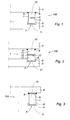
- the anode assembly 100 comprises an anode 3, typically of carbon, and an anode support 4 for the production of aluminum by electrolysis according to the Hall-Héroult method.
- the anode 3 is suspended from the anode support 4 by an electrical connection element 1 comprising a sealing portion 21 ensuring the attachment to the anode 3 and the electrical conduction to the anode 3, and an out-seal portion 22 ensuring the mechanical suspension of the anode 3.
- the anode 3 comprises in its upper part a recess 7 in which the sealing portion 21 of the electrical connecting element 1 is housed and fixed by a seal 8 of an electrically conductive material, cast iron for example.
- the sealing portion 21 is therefore the lower part of the electrical connection element 1 which is caught in the seal 8, in contrast to the out-seal portion 22 which extends above the seal 8.
- any other material suitable for sealing 8 may be used, especially sticky carbon paste.
- This seal 8 covers all the surfaces of the recess 7 and the sealing portion 21 of the electrical connecting element 1 housed in the recess 7.
- the seal 8 may otherwise extend along the side walls of the the sealing portion 21 and not on the underside.
- the anode assembly also comprises a bead 9 of electrically conductive material, arranged to provide the electrical and mechanical connection between the anode support 4 and the electrical connection element 1, more particularly in the upper part of the out-seal portion 22 of the electrical connecting element 1.
- the electrical connecting element 1 is typically made of steel and has a cylinder shape.
- the bead 9 may be formed by a cupro-type copper-based weld disposed laterally at the interface between the electrical connection element 1 and the anode support 4.
- the figure 1 also illustrates in the out-seal portion 22 a thermally insulating element 6 which extends in a plane transverse to the direction of extension of the electrical connecting element 1 between the anode 3 and the anode support 4.
- the electrical connection element 1 comprises a housing 5, formed of a notch opening laterally and in which is disposed a thermally insulator 6.
- This thermally insulating element 6 may consist of any suitable refractory materials, such as sintered powder, film or fiber felt, comprising at least one refractory material.
- the out-seal portion 22 of the electrical connection element 1 comprises a first portion 11 and a second portion 12 distinct from the first portion 11 and between which a thermally insulating member 6 is disposed.
- the heat transfer by conduction is thus significantly reduced by the fact that the entire cross section of the electrical connecting element 1 is covered by the thermally insulating element 6.
- the electrical conduction is then provided by a complementary bead 13 of an electrically conductive material disposed laterally to the thermally insulating element 6 so as to electrically and mechanically connect the first portion 11 and the second portion 12.
- the embodiment illustrated in figure 3 differs from the two previous embodiments, in particular in that the thermally insulating element 6 is disposed at the interface between the electrical connection element 1 and the anode support 4.
- the cord 9 is arranged laterally to the insulating element 6 to provide an electrical and mechanical connection between the out-sealing portion 22 of the electrical connecting element 1 and the anode support 4.
- the out-seal portion 22 of the electrical connection element 1 comprises a first portion 11 disposed on the side of the anode support 4 and a second portion 12 disposed on the side of the anode 3.
- the cross section of the first portion 11 is reduced compared to that of the second portion 12 to limit heat transfer.
- the anode assembly comprises a thermally insulating element 6 disposed between the electrical connection element 1 and the anode support 4 and further comprises a thermally insulating element 6 disposed between the first portion 11 and the second portion 12.
- An electrical conduction member 14, such as a copper plate, is arranged to provide an electrical connection between the second portion 12 and the anode support 4 and rests against a portion of the first portion 11.
- the thermal transfer is very limited by the presence of the two thermally insulating elements 6 and the reduced cross section of the first portion 11. Moreover, the electrical connection is provided by the cord 9 and the complementary bead 13 as well as the highly conductive copper plate. The section of the copper plate being reduced, the thermal conduction thereby remains very limited.
- the present invention provides an anode assembly 100 to effectively reduce the heat loss between the anode 3 and the anode carrier 4 by reducing heat transfer while also ensuring the maintenance of a very good electrical conduction.
Landscapes
- Chemical & Material Sciences (AREA)
- Engineering & Computer Science (AREA)
- Chemical Kinetics & Catalysis (AREA)
- Electrochemistry (AREA)
- Materials Engineering (AREA)
- Metallurgy (AREA)
- Organic Chemistry (AREA)
- Electrolytic Production Of Metals (AREA)
- Secondary Cells (AREA)
- Connection Of Batteries Or Terminals (AREA)
- Microwave Tubes (AREA)
Description
La présente invention concerne un ensemble anodique comprenant un support d'anode et une anode pour la production d'aluminium.The present invention relates to an anode assembly comprising an anode support and an anode for the production of aluminum.
L'aluminium est classiquement produit dans des alumineries, par électrolyse, selon le procédé de Hall-Héroult. A cet effet, on prévoit une cuve d'électrolyse comprenant un caisson et un revêtement intérieur en matériau réfractaire. La cuve d'électrolyse comprend également des blocs cathodiques agencés au fond du caisson, parcourus par des barres conductrices destinées à collecter le courant d'électrolyse et le conduire à une cuve d'électrolyse suivante. La cuve d'électrolyse comprend également au moins un bloc anodique suspendu à un support d'anode, tel qu'une traverse, le bloc anodique étant plongé partiellement dans un bain électrolytique, au-dessus des blocs cathodiques. Une nappe d'aluminium liquide, recouvrant les blocs cathodiques, se forme au fur et à mesure de la réaction. Le passage du courant s'effectue du support d'anode vers la cathode via le bloc anodique et le bain électrolytique à une température d'environ 970°C dans lequel l'alumine est dissoute. Ce courant d'électrolyse présente une intensité pouvant atteindre plusieurs centaines de milliers d'ampères. La suspension du bloc anodique est alors réalisée par un élément intermédiaire, capable de véhiculer ce fort courant, de résister à ces très fortes températures mais qui est également capable de soutenir le poids de l'anode, tel qu'un rondin réalisé en acier.Aluminum is conventionally produced in aluminum smelters, by electrolysis, according to the Hall-Héroult process. For this purpose, there is provided an electrolysis cell comprising a box and an inner lining of refractory material. The electrolytic cell also comprises cathode blocks arranged at the bottom of the box, traversed by conductive bars for collecting the electrolysis current and leading it to a subsequent electrolysis cell. The electrolysis cell also comprises at least one anode block suspended on an anode support, such as a cross member, the anode block being partially immersed in an electrolytic bath, above the cathode blocks. A liquid aluminum sheet, covering the cathode blocks, is formed as and when the reaction. The flow of current is from the anode carrier to the cathode via the anode block and the electrolytic bath at a temperature of about 970 ° C wherein the alumina is dissolved. This electrolysis current has an intensity of up to several hundreds of thousands of amperes. The suspension of the anode block is then carried out by an intermediate element, capable of carrying this strong current, of resisting these very high temperatures but which is also capable of supporting the weight of the anode, such as a log made of steel.
Or dans un tel dispositif, un flux thermique très important se forme entre l'anode en carbone et le support d'anode. Ce transfert thermique représente une perte énergétique importante et préjudiciable dans le processus d'électrolyse.In such a device, a very large heat flow is formed between the carbon anode and the anode support. This heat transfer represents a significant and detrimental energy loss in the electrolysis process.
Il a été observé, tel que divulgué dans le brevet
Il est connu de la publication de brevet
Aussi, l'invention a pour objectif de proposer un dispositif permettant de limiter les pertes thermiques sans affecter sa conductance électrique tout en limitant les coûts. Pour ce faire, l'invention propose un ensemble anodique pour la production d'aluminium comprenant une anode, un support d'anode, et un élément de liaison électrique comportant une portion de scellement et une portion hors-scellement pour relier électriquement le support d'anode à l'anode, dans lequel l'anode comprend un évidement dans lequel est logé la portion de scellement de l'élément de liaison électrique et dans lequel un scellement formé en un matériau électriquement conducteur retient l'élément de liaison électrique, l'ensemble anodique comprenant au moins un élément thermiquement isolant agencé entre deux parois se faisant face appartenant à la portion hors-scellement de l'élément de liaison électrique et/ou au support d'anode pour réduire le transfert thermique entre l'anode et le support d'anode lors de la production d'aluminium.Also, the invention aims to provide a device for limiting heat losses without affecting its electrical conductance while limiting costs. To do this, the invention proposes an anode assembly for the production of aluminum comprising an anode, an anode support, and an electrical connection element comprising a sealing portion and an out-sealing portion for electrically connecting the support of anode at the anode, wherein the anode comprises a recess in which is housed the sealing portion of the electrical connecting member and wherein a seal formed of an electrically conductive material retains the electrical connecting member, anode assembly comprising at least one thermally insulating element arranged between two facing walls belonging to the out-sealing portion of the electrical connection element and / or the anode support to reduce the heat transfer between the anode and the anode support when producing aluminum.
Ainsi, les pertes thermiques par rayonnement entre les surfaces entre lesquelles l'élément thermiquement isolant est intercalé sont empêchées, ce qui permet de réduire les pertes thermiques de cet ensemble anodique tout en conservant une liaison électrique satisfaisante entre le support d'anode et l'anode.Thus, the heat losses by radiation between the surfaces between which the thermally insulating element is inserted are prevented, thereby reducing the thermal losses of the anode assembly while maintaining a satisfactory electrical connection between the anode support and the anode.
Le scellement permet d'assurer une fonction de conduction électrique tout en permettant une solidarisation mécanique entre l'élément de liaison électrique et l'anode. Le scellement s'étend typiquement le long de la paroi latérale de la portion de scellement de l'élément de liaison électrique. Ce contact latéral entre le scellement et l'élément de liaison électrique permet une très bonne conduction électrique, mais également une très bonne conductivité thermique entre l'anode et l'élément de liaison électrique.The sealing ensures an electrical conduction function while allowing mechanical attachment between the electrical connection element and the anode. Sealing typically extends along the side wall of the sealing portion of the electrical connecting member. This lateral contact between the seal and the electrical connection element allows a very good electrical conduction, but also a very good thermal conductivity between the anode and the electrical connection element.
De préférence, les deux parois se faisant face sont reliées électriquement et mécaniquement au moyen d'un cordon de matériau électriquement conducteur, plus particulièrement un cordon de soudure. Ainsi, le cordon de matériau électriquement conducteur assure la tenue mécanique et la conduction électrique dans la zone où les deux parois sont séparées par l'élément thermiquement isolant.Preferably, the two walls facing each other are electrically and mechanically connected by means of a bead of electrically conductive material, plus particularly a weld seam. Thus, the bead of electrically conductive material provides mechanical strength and electrical conduction in the area where the two walls are separated by the thermally insulating element.
Selon une disposition avantageuse, l'élément de liaison électrique s'étend dans une direction d'extension entre l'anode et le support d'anode et au moins un élément thermiquement isolant s'étend dans un plan transversal à la direction d'extension. Dans cette configuration, le transfert thermique selon une section transversale de l'élément de liaison électrique est nettement diminué car les pertes thermiques par rayonnement entre les surfaces entre lesquelles l'élément thermiquement isolant est intercalé sont empêchées.According to an advantageous arrangement, the electrical connection element extends in an extension direction between the anode and the anode support and at least one thermally insulating element extends in a plane transverse to the direction of extension. . In this configuration, the thermal transfer along a cross-section of the electrical connection element is significantly reduced because the heat losses by radiation between the surfaces between which the thermally insulating element is interposed are prevented.
Selon une possibilité préférée, au moins un élément thermiquement isolant est agencé entre une paroi de l'élément de liaison électrique et une paroi du support d'anode. Cette configuration avec un élément thermiquement isolant intercalé entre l'élément de liaison électrique et le support d'anode est particulièrement avantageuse en ce que le flux thermique par rayonnement et conduction entre l'élément de liaison électrique et le support d'anode est limité. La présence d'un isolant thermique à cette interface est ainsi très simple à mettre en oeuvre et très efficace pour limiter les pertes énergétiques.According to a preferred possibility, at least one thermally insulating element is arranged between a wall of the electrical connection element and a wall of the anode support. This configuration with a thermally insulating element interposed between the electrical connection element and the anode support is particularly advantageous in that the radiative heat flux and conduction between the electrical connection element and the anode support is limited. The presence of a thermal insulation at this interface is thus very simple to implement and very effective in limiting energy losses.
De préférence, l'ensemble anodique comprend un cordon de matériau électriquement conducteur, plus particulièrement un cordon de soudure, agencé pour relier électriquement et mécaniquement l'élément de liaison électrique et le support d'anode. Ainsi, l'élément de liaison électrique assure le soutien mécanique de l'anode tout en favorisant la conduction électrique entre le support d'anode et l'anode.Preferably, the anode assembly comprises a bead of electrically conductive material, more particularly a weld bead, arranged to electrically and mechanically connect the electrical connection element and the anode support. Thus, the electrical connection element provides mechanical support for the anode while promoting electrical conduction between the anode support and the anode.
Il a été observé par la demanderesse que le courant électrique circulant entre deux pièces soudées entre elles et dont les parois se font face et sont en contact passe en quasi-totalité par les soudures. Le positionnement d'un élément thermiquement isolant entre ces parois se faisant face permet donc un gain thermique et n'impact pas la conductivité électrique de l'ensemble anodique.It has been observed by the Applicant that the electric current flowing between two parts welded together and whose walls are facing and are in contact passes almost entirely by the welds. The positioning of a thermally insulating element between these facing walls therefore allows a thermal gain and does not impact the electrical conductivity of the anode assembly.
Selon une variante, la portion hors-scellement de l'élément de liaison électrique délimite un logement dans lequel est disposé au moins un élément thermiquement isolant. L'élément thermiquement isolant empêche les pertes thermiques par rayonnement entre des parois opposées du logement.According to a variant, the out-sealing portion of the electrical connection element delimits a housing in which is disposed at least one thermally insulating element. The thermally insulating element prevents heat losses by radiation between opposite walls of the housing.
Typiquement, le logement est formé par une encoche dans l'élément de liaison électrique. Cette encoche peut être notamment usinée dans l'élément de liaison électrique.Typically, the housing is formed by a notch in the electrical connection element. This notch may in particular be machined in the electrical connection element.
De préférence, l'encoche débouche latéralement de la portion hors-scellement de l'élément de liaison électrique de sorte que l'élément thermiquement isolant est facilement introduit dans l'élément de liaison électrique. Cette variante est ainsi très simple à mettre en pratique.Preferably, the notch opens out laterally of the out-sealing portion of the electrical connection element so that the thermally insulating element is easily introduced into the electrical connection element. This variant is thus very simple to put into practice.
Selon une possibilité, la portion hors-scellement de l'élément de liaison électrique comprend une première portion et une seconde portion, les première et seconde portions étant séparées par au moins un élément thermiquement isolant. Ainsi, le transfert thermique par conduction est limité sur la section transversale de la portion hors-scellement de l'élément de liaison électrique entre les première et seconde portions.According to one possibility, the out-sealing portion of the electrical connection element comprises a first portion and a second portion, the first and second portions being separated by at least one thermally insulating element. Thus, conductive heat transfer is limited on the cross-section of the out-seal portion of the electrical connecting member between the first and second portions.
De préférence, un cordon complémentaire de matériau électriquement conducteur, plus particulièrement un cordon de soudure, est agencé pour recouvrir au moins une partie dudit au moins un élément thermiquement isolant et pour relier électriquement et mécaniquement la première portion et la seconde portion. La tenue mécanique et la conduction électrique entre le support d'anode et l'anode reste ainsi très satisfaisante, pour une réduction du transfert thermique importante. L'élément thermiquement isolant est en outre protégé par cet enfermement dans le logement.Preferably, a complementary bead of electrically conductive material, more particularly a bead, is arranged to cover at least a portion of said at least one thermally insulating element and to electrically and mechanically connect the first portion and the second portion. The mechanical strength and the electrical conduction between the anode support and the anode thus remains very satisfactory, for a reduction of the important heat transfer. The thermally insulating element is further protected by this enclosure in the housing.
Avantageusement, l'ensemble anodique comprend en outre un élément thermiquement isolant disposé à l'interface entre l'élément de liaison électrique et le support d'anode. Ainsi, la réduction du transfert thermique est encore améliorée.Advantageously, the anode assembly further comprises a thermally insulating element disposed at the interface between the electrical connection element and the anode support. Thus, the reduction of heat transfer is further improved.
Dans une variante, la première portion disposée du côté du support d'anode présente une section transversale réduite par rapport à celle de la seconde portion disposée du côté de l'anode et un organe de conduction électrique est agencé pour relier électriquement la seconde portion et le support d'anode. Dans cette configuration, la réduction de la section de la première portion réduisant le transfert thermique reste sans incidence sur la conduction électrique de par la présence l'organe de conduction électrique.In a variant, the first portion disposed on the side of the anode support has a reduced cross section relative to that of the second portion disposed on the side of the anode and an electrical conduction member is arranged to electrically connect the second portion and the anode support. In this configuration, the reduction of the section of the first portion reducing the heat transfer remains without impact on the electrical conduction by the presence of the electrical conduction member.
Typiquement, l'élément de liaison électrique comprend une forme sensiblement cylindrique, telle qu'un rondin en acier. L'acier permet en effet de résister à l'environnement corrosif dans la cuve d'électrolyse, aux températures très élevées et est suffisamment résistant pour soutenir l'anode.Typically, the electrical connection element comprises a substantially cylindrical shape, such as a steel log. The steel makes it possible to withstand the corrosive environment in the electrolysis cell, at very high temperatures and is sufficiently resistant to support the anode.
Selon une possibilité, au moins un élément thermiquement isolant comprend une forme de plaque, formée notamment d'une poudre frittée, d'un film ou d'un feutre de fibres comprenant au moins un matériau réfractaire. La poudre frittée présente l'avantage d'être facilement conformée et est adaptable pour être disposée dans toute configuration géométrique de l'ensemble anodique.According to one possibility, at least one thermally insulating element comprises a plate form, formed in particular of a sintered powder, a film or a fiber felt comprising at least one refractory material. The sintered powder has the advantage of being easily shaped and is adaptable to be disposed in any geometric configuration of the anode assembly.
D'autres aspects, buts et avantages de la présente invention apparaîtront mieux à la lecture de la description suivante de modes de réalisation de celle-ci, donnée à titre d'exemples non limitatifs et faite en référence aux dessins annexés. Les figures ne respectent pas nécessairement l'échelle de tous les éléments représentés de sorte à améliorer leur lisibilité. Dans la suite de la description, par souci de simplification, des éléments identiques, similaires ou équivalents des différentes formes de réalisation portent les mêmes références numériques.
- La
figure 1 illustre un ensemble anodique selon un premier mode de réalisation de l'invention. - La
figure 2 illustre un ensemble anodique selon une variante de réalisation de l'invention. - La
figure 3 illustre un ensemble anodique selon un second mode de réalisation de l'invention. - La
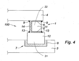
figure 4 illustre un ensemble anodique selon encore un autre mode de réalisation de l'invention.
- The
figure 1 illustrates an anode assembly according to a first embodiment of the invention. - The
figure 2 illustrates an anode assembly according to an alternative embodiment of the invention. - The
figure 3 illustrates an anode assembly according to a second embodiment of the invention. - The
figure 4 illustrates an anode assembly according to yet another embodiment of the invention.
Comme illustré à la
L'anode 3 comprend dans sa partie supérieure un évidement 7 dans lequel la portion de scellement 21 de l'élément de liaison électrique 1 est logée et fixée par un scellement 8 en un matériau électriquement conducteur, en fonte par exemple. La portion de scellement 21 est donc la partie inférieure de l'élément de liaison électrique 1 qui se trouve prise dans le scellement 8, à contrario de la portion hors-scellement 22 qui s'étend au-dessus du scellement 8. Il est bien entendu dans le présent document que tout autre matériau adapté au scellement 8 peut être utilisé, notamment de la pâte carbonée collante. Ce scellement 8 recouvre l'ensemble des surfaces de l'évidement 7 et de la portion de scellement 21 de l'élément de liaison électrique 1 logé dans l'évidement 7. Le scellement 8 peut sinon s'étendre le long des parois latérales de la portion de scellement 21 et non sur le dessous.The
L'ensemble anodique comporte également un cordon 9 de matériau électriquement conducteur, agencé pour assurer la liaison électrique et mécanique entre le support d'anode 4 et l'élément de liaison électrique 1, plus particulièrement en partie supérieure de la portion hors-scellement 22 de l'élément de liaison électrique 1. L'élément de liaison électrique 1 est typiquement réalisé en acier et présente une forme de cylindre. Le cordon 9 peut être formé par une soudure à base de cuivre de type cupro, disposée latéralement à l'interface entre l'élément de liaison électrique 1 et le support d'anode 4.The anode assembly also comprises a
La
Dans le mode de réalisation illustré à la
Le mode de réalisation illustré à la
Selon le mode de réalisation illustré à la
Ainsi, la présente invention propose un ensemble anodique 100 permettant de réduire efficacement la perte thermique entre l'anode 3 et le support anodique 4 par diminution du transfert thermique tout en assurant par ailleurs le maintien d'une très bonne conduction électrique.Thus, the present invention provides an
Claims (13)
- Anode assembly (100) for the production of aluminum comprising an anode (3), an anode support (4), and an electrical connecting element (1) having a sealing portion (21) and a non-sealing portion (22) for electrically connecting the anode support (4) to the anode (3), wherein the anode (3) comprises a recess (7) in which is located the sealing portion of the electrical connecting element (1) and wherein a seal (8) formed of an electrically conductive material holds the electrical connecting element (1), characterized in that at least one thermally insulating element (6) is arranged between two walls facing each other belonging to the non-sealing portion (22) of the electrical connecting element (1) and/or to the anode support (4) to reduce heat transfer between the anode (3) and the anode support (4) during the production of aluminum.
- Anode assembly (100) according to claim 1, wherein the two walls facing each other are electrically and mechanically connected by means of a bead (9, 13) of electrically conductive material.
- Anode assembly (100) according to one of claims 1 to 2, wherein the electrical connecting element (1) extends in a direction of extension between the anode (3) and the anode support (4) and wherein the at least one thermally insulating element (6) extends in a plane transverse to the direction of extension.
- Anode assembly (100) according to one of claims 1 to 3, wherein the at least one thermally insulating element (6) is arranged between one wall of the non-sealing portion (22) of the electrical connecting element (1) and one wall of the anode support (4).
- Anode assembly (100) according to one of claims 1 to, 4 wherein the anode assembly (100) further comprises a bead (9) of electrically conductive material arranged to electrically and mechanically connect the electrical connecting element (1) and the anode support (4).
- Anode assembly (100) according to one of claims 1 to 5, wherein the non-sealing portion (22) of the electrical connecting element (1) defines a housing (5) wherein the at least one thermally insulating element (6) is arranged.
- Anode assembly (100) according to claim 6, wherein the housing (5) is formed by a notch in the non-sealing portion (22) of the electrical connecting element (1).
- Anode assembly (100) according to claim 7, wherein the notch opens out laterally from the non-sealing portion (22) of the electrical connecting element (1).
- Anode assembly (100) according to one of claims 1 to 8, wherein the non-sealing portion (22) of the electrical connecting element (1) comprises a first portion (11) and a second portion (12), the first and second portions (11,12) being separated by the at least one thermally insulating element (6).
- Anode assembly (100) according to claim 9, wherein an additional bead (13) of electrically conductive material is arranged to cover at least a portion of said at least one thermally insulating element (6) and to electrically and mechanically connect the first portion (11) and the second portion (12).
- Anode assembly (100) according to one of claims 9 to 10, wherein the first portion (11) arranged on the side of the anode support (4) has a smaller cross section reduced relative to that of the second portion (12) arranged on the side of the anode (3) and wherein an electrical conductivity component (14) is arranged to electrically connect the second portion (12) and the anode support (4).
- Anode assembly (100) according to one of claims 1 to 10, wherein the electrically conductive material comprises a cylindrical shape, such as a steel stub.
- Anode assembly (100) according to one of claims 1 to 12, wherein the at least one thermally insulating element (6) comprises a plate shape, formed, in particular, from a sintered powder, a film or a fiber mat including at least one refractory material.
Applications Claiming Priority (2)
| Application Number | Priority Date | Filing Date | Title |
|---|---|---|---|
| FR1401517 | 2014-07-04 | ||
| PCT/IB2015/001109 WO2016001741A1 (en) | 2014-07-04 | 2015-07-01 | Anode assembly |
Publications (3)
| Publication Number | Publication Date |
|---|---|
| EP3164530A1 EP3164530A1 (en) | 2017-05-10 |
| EP3164530A4 EP3164530A4 (en) | 2018-01-17 |
| EP3164530B1 true EP3164530B1 (en) | 2019-04-24 |
Family
ID=51483482
Family Applications (1)
| Application Number | Title | Priority Date | Filing Date |
|---|---|---|---|
| EP15814208.3A Active EP3164530B1 (en) | 2014-07-04 | 2015-07-01 | Anode assembly |
Country Status (10)
| Country | Link |
|---|---|
| US (1) | US10443140B2 (en) |
| EP (1) | EP3164530B1 (en) |
| CN (1) | CN106471160B (en) |
| AR (1) | AR101928A1 (en) |
| AU (1) | AU2015282392B2 (en) |
| BR (1) | BR112016028617B1 (en) |
| CA (1) | CA2952166C (en) |
| DK (1) | DK179336B1 (en) |
| EA (1) | EA037127B1 (en) |
| WO (1) | WO2016001741A1 (en) |
Family Cites Families (10)
| Publication number | Priority date | Publication date | Assignee | Title |
|---|---|---|---|---|
| GB962599A (en) * | 1961-08-03 | 1964-07-01 | Montedison Spa | Electrolytic furnace for aluminium production |
| US3509030A (en) * | 1967-12-15 | 1970-04-28 | Alcan Res & Dev | Casing liner |
| DE3009098C2 (en) * | 1979-12-21 | 1983-02-24 | Schweizerische Aluminium AG, 3965 Chippis | Method of conducting electricity between electrolytic furnaces |
| FR2527229A1 (en) * | 1982-05-18 | 1983-11-25 | Aluminium Grece | METHOD FOR CALORIFUTING PRECISE ANODES IN ELECTROLYSIS CUPES FOR ALUMINUM PRODUCTION |
| FR2565258B1 (en) * | 1984-05-29 | 1986-08-29 | Pechiney Aluminium | PARTIALLY SHRINKED CARBON ANODE FOR TANKS FOR THE PRODUCTION OF ALUMINUM BY ELECTROLYSIS |
| AUPQ218899A0 (en) * | 1999-08-13 | 1999-09-02 | Jakovac, Vjekoslav | Anode assembly comprising separation of electrical and mechanical functions of the assembly |
| FR2900938B1 (en) * | 2006-05-15 | 2008-06-20 | Ecl Soc Par Actions Simplifiee | METHOD FOR MANUFACTURING ANODES FOR THE PRODUCTION OF ALUMINUM BY IGNEE ELECTROLYSIS, THE SAID ANODES AND THEIR USE |
| EP2006419A1 (en) | 2007-06-22 | 2008-12-24 | Sgl Carbon Ag | Reduced voltage drop anode assembly for aluminium electrolysis cell |
| CN101709485B (en) * | 2009-12-18 | 2012-07-04 | 中国铝业股份有限公司 | Aluminum electrolytic cell for producing virgin aluminum by inert anode |
| WO2012100340A1 (en) * | 2011-01-28 | 2012-08-02 | UNIVERSITé LAVAL | Anode and connector for a hall-heroult industrial cell |
-
2015
- 2015-07-01 US US15/323,904 patent/US10443140B2/en active Active
- 2015-07-01 CN CN201580034611.0A patent/CN106471160B/en active Active
- 2015-07-01 EA EA201790130A patent/EA037127B1/en not_active IP Right Cessation
- 2015-07-01 AU AU2015282392A patent/AU2015282392B2/en active Active
- 2015-07-01 CA CA2952166A patent/CA2952166C/en active Active
- 2015-07-01 EP EP15814208.3A patent/EP3164530B1/en active Active
- 2015-07-01 WO PCT/IB2015/001109 patent/WO2016001741A1/en active Application Filing
- 2015-07-01 BR BR112016028617-0A patent/BR112016028617B1/en active IP Right Grant
- 2015-07-03 AR ARP150102144A patent/AR101928A1/en active IP Right Grant
-
2016
- 2016-12-08 DK DKPA201670975A patent/DK179336B1/en active
Non-Patent Citations (1)
| Title |
|---|
| None * |
Also Published As
| Publication number | Publication date |
|---|---|
| WO2016001741A1 (en) | 2016-01-07 |
| US10443140B2 (en) | 2019-10-15 |
| CA2952166C (en) | 2022-07-26 |
| EP3164530A4 (en) | 2018-01-17 |
| CN106471160B (en) | 2018-10-16 |
| AU2015282392A1 (en) | 2017-01-05 |
| EA037127B1 (en) | 2021-02-09 |
| AR101928A1 (en) | 2017-01-25 |
| CN106471160A (en) | 2017-03-01 |
| BR112016028617A2 (en) | 2017-08-22 |
| US20170167039A1 (en) | 2017-06-15 |
| BR112016028617B1 (en) | 2021-11-03 |
| CA2952166A1 (en) | 2016-01-07 |
| AU2015282392B2 (en) | 2019-03-14 |
| EA201790130A1 (en) | 2017-06-30 |
| DK201670975A1 (en) | 2017-01-09 |
| DK179336B1 (en) | 2018-05-14 |
| EP3164530A1 (en) | 2017-05-10 |
Similar Documents
| Publication | Publication Date | Title |
|---|---|---|
| CA2919331C (en) | Electrolytic device and anode assembly intended for the production of aluminium, electrolytic cell and apparatus comprising such a device | |
| EP0167461A1 (en) | Carbonaceous anode with partially restricted studs for electrolytic aluminium production pots | |
| EP3164530B1 (en) | Anode assembly | |
| WO2015110904A1 (en) | Electrolysis tank comprising an anode assembly contained in a containment enclosure | |
| EP3030694A1 (en) | Electrolytic cell intended for the production of aluminium and electrolytic smelter comprising this cell | |
| EP0169152A1 (en) | Modular cathodic block and cathode with a low-voltage drop for Hall-Heroult electrolysis vats | |
| CA2935439A1 (en) | Electrolysis tank comprising an anodic assembly hoisting device | |
| CA1214752A (en) | Cathode bar with metallic footing for hall-heroult type electrolytic cells | |
| EP0126700B1 (en) | Sub-cathode shield comprising deformable areas for Hall-Héroult electrolytic pots | |
| FR3012473A1 (en) | SEALING DEVICE FOR ELECTROLYSIS CELL HOOD | |
| FR2961828A1 (en) | DEVICE FOR EXTRACTING SHORT CIRCUITS WHEN CIRCUITING AN ELECTROLYSIS CELL FOR THE PRODUCTION OF ALUMINUM | |
| FR2925531A1 (en) | SUPPORT DEVICE FOR ELECTRODES IN AN ELECTROLYSIS INSTALLATION | |
| CA3122500A1 (en) | Anode assembly and electrolytic cell comprising said anode assembly | |
| FR2546184A1 (en) | Cathode rod comprising a metal soleplate for Hall-Héroult electrolysis cells | |
| WO2015110906A1 (en) | Anode assembly and associated production method | |
| FR3016892A1 (en) | DEVICE FOR PREHEATING AN ANODE ASSEMBLY. | |
| WO2023087107A1 (en) | Interior lining system for an electrolytic cell | |
| FR2971794A1 (en) | Device for cathodic protection of a metal structure such as a pipe or a tank to prevent its corrosion, comprises a continuous current generator or a rectifier provided with a cathodic connection and an anodic connection, and an electrolyte | |
| EP3099842B1 (en) | Electrolysis tank casing | |
| EP3899105A1 (en) | Anode assembly and associated manufacturing method | |
| WO2012172196A1 (en) | Electrolysis cell intended to be used to produce aluminium | |
| FR3078714A1 (en) | CATHODIC ASSEMBLY FOR ELECTROLYTIC TANK | |
| OA17791A (en) | Electrolysis device and anode assembly intended for the production of aluminum, electrolysis cell and installation comprising such a device |
Legal Events
| Date | Code | Title | Description |
|---|---|---|---|
| STAA | Information on the status of an ep patent application or granted ep patent |
Free format text: STATUS: THE INTERNATIONAL PUBLICATION HAS BEEN MADE |
|
| PUAI | Public reference made under article 153(3) epc to a published international application that has entered the european phase |
Free format text: ORIGINAL CODE: 0009012 |
|
| STAA | Information on the status of an ep patent application or granted ep patent |
Free format text: STATUS: REQUEST FOR EXAMINATION WAS MADE |
|
| 17P | Request for examination filed |
Effective date: 20161207 |
|
| AK | Designated contracting states |
Kind code of ref document: A1 Designated state(s): AL AT BE BG CH CY CZ DE DK EE ES FI FR GB GR HR HU IE IS IT LI LT LU LV MC MK MT NL NO PL PT RO RS SE SI SK SM TR |
|
| AX | Request for extension of the european patent |
Extension state: BA ME |
|
| DAV | Request for validation of the european patent (deleted) | ||
| RAX | Requested extension states of the european patent have changed |
Extension state: BA Payment date: 20161207 |
|
| A4 | Supplementary search report drawn up and despatched |
Effective date: 20171218 |
|
| RIC1 | Information provided on ipc code assigned before grant |
Ipc: C25C 3/08 20060101ALI20171212BHEP Ipc: C25C 3/12 20060101ALI20171212BHEP Ipc: C25C 3/16 20060101AFI20171212BHEP |
|
| REG | Reference to a national code |
Ref country code: DE Ref legal event code: R079 Ref document number: 602015029025 Country of ref document: DE Free format text: PREVIOUS MAIN CLASS: C25C0003120000 Ipc: C25C0003160000 |
|
| GRAP | Despatch of communication of intention to grant a patent |
Free format text: ORIGINAL CODE: EPIDOSNIGR1 |
|
| STAA | Information on the status of an ep patent application or granted ep patent |
Free format text: STATUS: GRANT OF PATENT IS INTENDED |
|
| RIC1 | Information provided on ipc code assigned before grant |
Ipc: C25C 3/08 20060101ALI20181018BHEP Ipc: C25C 3/12 20060101ALI20181018BHEP Ipc: C25C 3/16 20060101AFI20181018BHEP |
|
| INTG | Intention to grant announced |
Effective date: 20181116 |
|
| GRAS | Grant fee paid |
Free format text: ORIGINAL CODE: EPIDOSNIGR3 |
|
| GRAA | (expected) grant |
Free format text: ORIGINAL CODE: 0009210 |
|
| STAA | Information on the status of an ep patent application or granted ep patent |
Free format text: STATUS: THE PATENT HAS BEEN GRANTED |
|
| AK | Designated contracting states |
Kind code of ref document: B1 Designated state(s): AL AT BE BG CH CY CZ DE DK EE ES FI FR GB GR HR HU IE IS IT LI LT LU LV MC MK MT NL NO PL PT RO RS SE SI SK SM TR |
|
| AX | Request for extension of the european patent |
Extension state: BA |
|
| REG | Reference to a national code |
Ref country code: GB Ref legal event code: FG4D Free format text: NOT ENGLISH |
|
| REG | Reference to a national code |
Ref country code: CH Ref legal event code: EP |
|
| REG | Reference to a national code |
Ref country code: AT Ref legal event code: REF Ref document number: 1124265 Country of ref document: AT Kind code of ref document: T Effective date: 20190515 Ref country code: IE Ref legal event code: FG4D Free format text: LANGUAGE OF EP DOCUMENT: FRENCH |
|
| REG | Reference to a national code |
Ref country code: DE Ref legal event code: R096 Ref document number: 602015029025 Country of ref document: DE |
|
| REG | Reference to a national code |
Ref country code: NL Ref legal event code: MP Effective date: 20190424 |
|
| REG | Reference to a national code |
Ref country code: LT Ref legal event code: MG4D |
|
| REG | Reference to a national code |
Ref country code: NO Ref legal event code: T2 Effective date: 20190424 |
|
| PG25 | Lapsed in a contracting state [announced via postgrant information from national office to epo] |
Ref country code: NL Free format text: LAPSE BECAUSE OF FAILURE TO SUBMIT A TRANSLATION OF THE DESCRIPTION OR TO PAY THE FEE WITHIN THE PRESCRIBED TIME-LIMIT Effective date: 20190424 |
|
| PG25 | Lapsed in a contracting state [announced via postgrant information from national office to epo] |
Ref country code: HR Free format text: LAPSE BECAUSE OF FAILURE TO SUBMIT A TRANSLATION OF THE DESCRIPTION OR TO PAY THE FEE WITHIN THE PRESCRIBED TIME-LIMIT Effective date: 20190424 Ref country code: LT Free format text: LAPSE BECAUSE OF FAILURE TO SUBMIT A TRANSLATION OF THE DESCRIPTION OR TO PAY THE FEE WITHIN THE PRESCRIBED TIME-LIMIT Effective date: 20190424 Ref country code: AL Free format text: LAPSE BECAUSE OF FAILURE TO SUBMIT A TRANSLATION OF THE DESCRIPTION OR TO PAY THE FEE WITHIN THE PRESCRIBED TIME-LIMIT Effective date: 20190424 Ref country code: ES Free format text: LAPSE BECAUSE OF FAILURE TO SUBMIT A TRANSLATION OF THE DESCRIPTION OR TO PAY THE FEE WITHIN THE PRESCRIBED TIME-LIMIT Effective date: 20190424 Ref country code: PT Free format text: LAPSE BECAUSE OF FAILURE TO SUBMIT A TRANSLATION OF THE DESCRIPTION OR TO PAY THE FEE WITHIN THE PRESCRIBED TIME-LIMIT Effective date: 20190824 Ref country code: SE Free format text: LAPSE BECAUSE OF FAILURE TO SUBMIT A TRANSLATION OF THE DESCRIPTION OR TO PAY THE FEE WITHIN THE PRESCRIBED TIME-LIMIT Effective date: 20190424 Ref country code: FI Free format text: LAPSE BECAUSE OF FAILURE TO SUBMIT A TRANSLATION OF THE DESCRIPTION OR TO PAY THE FEE WITHIN THE PRESCRIBED TIME-LIMIT Effective date: 20190424 |
|
| PG25 | Lapsed in a contracting state [announced via postgrant information from national office to epo] |
Ref country code: RS Free format text: LAPSE BECAUSE OF FAILURE TO SUBMIT A TRANSLATION OF THE DESCRIPTION OR TO PAY THE FEE WITHIN THE PRESCRIBED TIME-LIMIT Effective date: 20190424 Ref country code: BG Free format text: LAPSE BECAUSE OF FAILURE TO SUBMIT A TRANSLATION OF THE DESCRIPTION OR TO PAY THE FEE WITHIN THE PRESCRIBED TIME-LIMIT Effective date: 20190724 Ref country code: LV Free format text: LAPSE BECAUSE OF FAILURE TO SUBMIT A TRANSLATION OF THE DESCRIPTION OR TO PAY THE FEE WITHIN THE PRESCRIBED TIME-LIMIT Effective date: 20190424 Ref country code: GR Free format text: LAPSE BECAUSE OF FAILURE TO SUBMIT A TRANSLATION OF THE DESCRIPTION OR TO PAY THE FEE WITHIN THE PRESCRIBED TIME-LIMIT Effective date: 20190725 Ref country code: PL Free format text: LAPSE BECAUSE OF FAILURE TO SUBMIT A TRANSLATION OF THE DESCRIPTION OR TO PAY THE FEE WITHIN THE PRESCRIBED TIME-LIMIT Effective date: 20190424 |
|
| REG | Reference to a national code |
Ref country code: AT Ref legal event code: MK05 Ref document number: 1124265 Country of ref document: AT Kind code of ref document: T Effective date: 20190424 |
|
| REG | Reference to a national code |
Ref country code: DE Ref legal event code: R097 Ref document number: 602015029025 Country of ref document: DE |
|
| PG25 | Lapsed in a contracting state [announced via postgrant information from national office to epo] |
Ref country code: SK Free format text: LAPSE BECAUSE OF FAILURE TO SUBMIT A TRANSLATION OF THE DESCRIPTION OR TO PAY THE FEE WITHIN THE PRESCRIBED TIME-LIMIT Effective date: 20190424 Ref country code: EE Free format text: LAPSE BECAUSE OF FAILURE TO SUBMIT A TRANSLATION OF THE DESCRIPTION OR TO PAY THE FEE WITHIN THE PRESCRIBED TIME-LIMIT Effective date: 20190424 Ref country code: AT Free format text: LAPSE BECAUSE OF FAILURE TO SUBMIT A TRANSLATION OF THE DESCRIPTION OR TO PAY THE FEE WITHIN THE PRESCRIBED TIME-LIMIT Effective date: 20190424 Ref country code: DK Free format text: LAPSE BECAUSE OF FAILURE TO SUBMIT A TRANSLATION OF THE DESCRIPTION OR TO PAY THE FEE WITHIN THE PRESCRIBED TIME-LIMIT Effective date: 20190424 Ref country code: RO Free format text: LAPSE BECAUSE OF FAILURE TO SUBMIT A TRANSLATION OF THE DESCRIPTION OR TO PAY THE FEE WITHIN THE PRESCRIBED TIME-LIMIT Effective date: 20190424 Ref country code: CZ Free format text: LAPSE BECAUSE OF FAILURE TO SUBMIT A TRANSLATION OF THE DESCRIPTION OR TO PAY THE FEE WITHIN THE PRESCRIBED TIME-LIMIT Effective date: 20190424 |
|
| PG25 | Lapsed in a contracting state [announced via postgrant information from national office to epo] |
Ref country code: MC Free format text: LAPSE BECAUSE OF FAILURE TO SUBMIT A TRANSLATION OF THE DESCRIPTION OR TO PAY THE FEE WITHIN THE PRESCRIBED TIME-LIMIT Effective date: 20190424 Ref country code: SM Free format text: LAPSE BECAUSE OF FAILURE TO SUBMIT A TRANSLATION OF THE DESCRIPTION OR TO PAY THE FEE WITHIN THE PRESCRIBED TIME-LIMIT Effective date: 20190424 Ref country code: IT Free format text: LAPSE BECAUSE OF FAILURE TO SUBMIT A TRANSLATION OF THE DESCRIPTION OR TO PAY THE FEE WITHIN THE PRESCRIBED TIME-LIMIT Effective date: 20190424 |
|
| PLBE | No opposition filed within time limit |
Free format text: ORIGINAL CODE: 0009261 |
|
| REG | Reference to a national code |
Ref country code: CH Ref legal event code: PL |
|
| STAA | Information on the status of an ep patent application or granted ep patent |
Free format text: STATUS: NO OPPOSITION FILED WITHIN TIME LIMIT |
|
| GBPC | Gb: european patent ceased through non-payment of renewal fee |
Effective date: 20190724 |
|
| PG25 | Lapsed in a contracting state [announced via postgrant information from national office to epo] |
Ref country code: TR Free format text: LAPSE BECAUSE OF FAILURE TO SUBMIT A TRANSLATION OF THE DESCRIPTION OR TO PAY THE FEE WITHIN THE PRESCRIBED TIME-LIMIT Effective date: 20190424 |
|
| 26N | No opposition filed |
Effective date: 20200127 |
|
| REG | Reference to a national code |
Ref country code: BE Ref legal event code: MM Effective date: 20190731 |
|
| PG25 | Lapsed in a contracting state [announced via postgrant information from national office to epo] |
Ref country code: GB Free format text: LAPSE BECAUSE OF NON-PAYMENT OF DUE FEES Effective date: 20190724 |
|
| PG25 | Lapsed in a contracting state [announced via postgrant information from national office to epo] |
Ref country code: BE Free format text: LAPSE BECAUSE OF NON-PAYMENT OF DUE FEES Effective date: 20190731 Ref country code: LU Free format text: LAPSE BECAUSE OF NON-PAYMENT OF DUE FEES Effective date: 20190701 Ref country code: CH Free format text: LAPSE BECAUSE OF NON-PAYMENT OF DUE FEES Effective date: 20190731 Ref country code: LI Free format text: LAPSE BECAUSE OF NON-PAYMENT OF DUE FEES Effective date: 20190731 Ref country code: SI Free format text: LAPSE BECAUSE OF FAILURE TO SUBMIT A TRANSLATION OF THE DESCRIPTION OR TO PAY THE FEE WITHIN THE PRESCRIBED TIME-LIMIT Effective date: 20190424 |
|
| PG25 | Lapsed in a contracting state [announced via postgrant information from national office to epo] |
Ref country code: IE Free format text: LAPSE BECAUSE OF NON-PAYMENT OF DUE FEES Effective date: 20190701 |
|
| PG25 | Lapsed in a contracting state [announced via postgrant information from national office to epo] |
Ref country code: CY Free format text: LAPSE BECAUSE OF FAILURE TO SUBMIT A TRANSLATION OF THE DESCRIPTION OR TO PAY THE FEE WITHIN THE PRESCRIBED TIME-LIMIT Effective date: 20190424 |
|
| PG25 | Lapsed in a contracting state [announced via postgrant information from national office to epo] |
Ref country code: MT Free format text: LAPSE BECAUSE OF FAILURE TO SUBMIT A TRANSLATION OF THE DESCRIPTION OR TO PAY THE FEE WITHIN THE PRESCRIBED TIME-LIMIT Effective date: 20190424 Ref country code: HU Free format text: LAPSE BECAUSE OF FAILURE TO SUBMIT A TRANSLATION OF THE DESCRIPTION OR TO PAY THE FEE WITHIN THE PRESCRIBED TIME-LIMIT; INVALID AB INITIO Effective date: 20150701 |
|
| PG25 | Lapsed in a contracting state [announced via postgrant information from national office to epo] |
Ref country code: MK Free format text: LAPSE BECAUSE OF FAILURE TO SUBMIT A TRANSLATION OF THE DESCRIPTION OR TO PAY THE FEE WITHIN THE PRESCRIBED TIME-LIMIT Effective date: 20190424 |
|
| PGFP | Annual fee paid to national office [announced via postgrant information from national office to epo] |
Ref country code: NO Payment date: 20230712 Year of fee payment: 9 |
|
| PGFP | Annual fee paid to national office [announced via postgrant information from national office to epo] |
Ref country code: DE Payment date: 20230613 Year of fee payment: 9 |
|
| PGFP | Annual fee paid to national office [announced via postgrant information from national office to epo] |
Ref country code: IS Payment date: 20240624 Year of fee payment: 10 |
|
| PGFP | Annual fee paid to national office [announced via postgrant information from national office to epo] |
Ref country code: FR Payment date: 20240621 Year of fee payment: 10 |