EP3164304B1 - Dispositif de balai d'essuie-glace - Google Patents
Dispositif de balai d'essuie-glace Download PDFInfo
- Publication number
- EP3164304B1 EP3164304B1 EP14735946.7A EP14735946A EP3164304B1 EP 3164304 B1 EP3164304 B1 EP 3164304B1 EP 14735946 A EP14735946 A EP 14735946A EP 3164304 B1 EP3164304 B1 EP 3164304B1
- Authority
- EP
- European Patent Office
- Prior art keywords
- type
- oscillating arm
- shaped cross
- section
- oscillating
- Prior art date
- Legal status (The legal status is an assumption and is not a legal conclusion. Google has not performed a legal analysis and makes no representation as to the accuracy of the status listed.)
- Not-in-force
Links
Images


Classifications
-
- B—PERFORMING OPERATIONS; TRANSPORTING
- B60—VEHICLES IN GENERAL
- B60S—SERVICING, CLEANING, REPAIRING, SUPPORTING, LIFTING, OR MANOEUVRING OF VEHICLES, NOT OTHERWISE PROVIDED FOR
- B60S1/00—Cleaning of vehicles
- B60S1/02—Cleaning windscreens, windows or optical devices
- B60S1/04—Wipers or the like, e.g. scrapers
- B60S1/32—Wipers or the like, e.g. scrapers characterised by constructional features of wiper blade arms or blades
- B60S1/40—Connections between blades and arms
- B60S1/4038—Connections between blades and arms for arms provided with a channel-shaped end
- B60S1/4045—Connections between blades and arms for arms provided with a channel-shaped end comprising a detachable intermediate element mounted on the channel-shaped end
- B60S1/4048—Connections between blades and arms for arms provided with a channel-shaped end comprising a detachable intermediate element mounted on the channel-shaped end the element being provided with retention means co-operating with the channel-shaped end of the arm
-
- B—PERFORMING OPERATIONS; TRANSPORTING
- B60—VEHICLES IN GENERAL
- B60S—SERVICING, CLEANING, REPAIRING, SUPPORTING, LIFTING, OR MANOEUVRING OF VEHICLES, NOT OTHERWISE PROVIDED FOR
- B60S1/00—Cleaning of vehicles
- B60S1/02—Cleaning windscreens, windows or optical devices
- B60S1/04—Wipers or the like, e.g. scrapers
- B60S1/32—Wipers or the like, e.g. scrapers characterised by constructional features of wiper blade arms or blades
- B60S1/38—Wiper blades
- B60S1/3848—Flat-type wiper blade, i.e. without harness
- B60S1/3849—Connectors therefor; Connection to wiper arm; Attached to blade
-
- B—PERFORMING OPERATIONS; TRANSPORTING
- B60—VEHICLES IN GENERAL
- B60S—SERVICING, CLEANING, REPAIRING, SUPPORTING, LIFTING, OR MANOEUVRING OF VEHICLES, NOT OTHERWISE PROVIDED FOR
- B60S1/00—Cleaning of vehicles
- B60S1/02—Cleaning windscreens, windows or optical devices
- B60S1/04—Wipers or the like, e.g. scrapers
- B60S1/32—Wipers or the like, e.g. scrapers characterised by constructional features of wiper blade arms or blades
- B60S1/38—Wiper blades
- B60S2001/3898—Wiper blades method for manufacturing wiper blades
-
- B—PERFORMING OPERATIONS; TRANSPORTING
- B60—VEHICLES IN GENERAL
- B60S—SERVICING, CLEANING, REPAIRING, SUPPORTING, LIFTING, OR MANOEUVRING OF VEHICLES, NOT OTHERWISE PROVIDED FOR
- B60S1/00—Cleaning of vehicles
- B60S1/02—Cleaning windscreens, windows or optical devices
- B60S1/04—Wipers or the like, e.g. scrapers
- B60S1/32—Wipers or the like, e.g. scrapers characterised by constructional features of wiper blade arms or blades
- B60S1/40—Connections between blades and arms
- B60S1/4038—Connections between blades and arms for arms provided with a channel-shaped end
- B60S1/4045—Connections between blades and arms for arms provided with a channel-shaped end comprising a detachable intermediate element mounted on the channel-shaped end
- B60S1/4048—Connections between blades and arms for arms provided with a channel-shaped end comprising a detachable intermediate element mounted on the channel-shaped end the element being provided with retention means co-operating with the channel-shaped end of the arm
- B60S2001/4054—Connections between blades and arms for arms provided with a channel-shaped end comprising a detachable intermediate element mounted on the channel-shaped end the element being provided with retention means co-operating with the channel-shaped end of the arm the intermediate element engaging the back part of the arm
Definitions
- the present invention relates to a windscreen wiper device of the flat blade type comprising an elastic, elongated carrier element, as well as an elongated wiper blade of a flexible material, which can be placed in abutment with a windscreen to be wiped, which wiper blade includes at least one longitudinal groove, in which groove a longitudinal strip of the carrier element is disposed, which windscreen wiper device comprises a connecting device for an oscillating arm, wherein said oscillating arm can be pivotally connected to said connecting device about a pivot axis near one end, with the interposition of a joint part, wherein said joint part comprises at least one resilient tongue arranged to engage into a correspondingly shaped hole provided in a base of a U-shaped cross-section of said oscillating arm, wherein said resilient tongue is hingeable between a inward position, wherein said wiper blade can be released from said oscillating arm, and an outward position, wherein said wiper blade can be retained on said oscillating arm.
- said oscillating arm is connected to a mounting head mounted on a drive shaft, wherein said oscillating arm at one end thereof is pivotally connected to the mounting head by means of a pivot pin and at another end thereof is connected to said wiper blade placed in abutment with said windscreen to be wiped.
- the shaft rotates alternately in a clockwise and in a counter-clockwise sense carrying the mounting head into rotation also, which in turn draws the oscillating arm into rotation and by means of said connecting device moves the wiper blade.
- Said oscillating arm can thus oscillate to-and-from between a first reversal position and a second reversal position.
- the oscillating arm In said first reversal position the oscillating arm extends parallel to a windscreen to be wiped and is located near a lower edge of said windscreen to be wiped. Also, in said second reversal position the oscillating arm extends also parallel to a windscreen to be wiped and is located in a central region or near a side edge of said windscreen to be wiped.
- the present invention also relates to a vehicle equipped with such a windscreen wiper device, as well as to a method for manufacturing such a windscreen wiper device.
- Such a windscreen wiper device is generally known from European patent publication no. 1 403 156 of the same Applicant.
- This prior art windscreen wiper device is designed as a "yokeless" wiper device or "flat blade", wherein no use is made of several yokes pivotally connected to each other, but wherein the wiper blade is biased by the carrier element, as a result of which it exhibits a specific curvature.
- the joint part comprises at least one resilient tongue engaging in a correspondingly shaped hole provided in the oscillating arm, wherein the resilient tongue is rotatable along an hinge axis between an outward position retaining the wiper blade onto the oscillating arm and an inward position releasing the wiper blade from the oscillating arm.
- the resilient tongue In order to connect the wiper blade onto the oscillating arm, the resilient tongue is initially pushed in against a spring force - as if it were a push button - and then allowed to spring back into the hole provided in the oscillating arm, thus snapping, that is clipping the resilient tongue into the hole. By subsequently pushing in again the resilient tongue against the spring force, the wiper blade may be released from the oscillating arm.
- this interconnection between said joint part and said oscillating arm is called a bayonet connection.
- DE-A-102011053090 shows the preamble of claims 1 and 14.
- the object of the invention is to provide an improved windscreen wiper device at minimum costs - without using complex machinery and additional tools -, while the connecting device and the oscillating arm can be interconnected in a reliable and secure manner, using less parts.
- a windscreen wiper device of the type referred to in the introduction is characterized according to the invention in that said resilient tongue comprises a first step and a second step, wherein said first step is arranged to abut an edge of said hole of an oscillating arm of a first type facing towards a free end thereof, wherein said second step is arranged to abut an edge of said hole of an oscillating arm of a second type facing towards a free end thereof, and wherein said oscillating arm of the first type and said oscillating arm of the second type mutually differ in a distance between legs of the U-shaped cross-section of said oscillating arms.
- an upper surface of said first step is located closer to said wiper blade (and in use thus to a windscreen to be wiped) than an upper surface of said second step.
- said joint part is detachably connected to said connecting device particularly through a snapping/clipping operation.
- said snapping operation is realized by pivotally engaging protrusions of said connecting device at the location of said pivot axis into recesses provided in said joint part.
- said joint part has an at least substantially U-shaped cross-section at the location of its attachment to said connecting device, wherein each leg of said U-shaped cross-section is provided with a recess provided coaxially with said pivot axis.
- the protrusions that function as bearing surfaces are spaced far apart, so that the forces exerted thereon will be relatively low.
- Said joint part is arranged to be connected to said connecting device for different U-shaped cross-sections of the oscillating arm, wherein said joint part is subsequently connected to said connecting device by said pivotally engaging protrusions of said connecting device, at the location of said pivot axis, in said recesses provided in said joint part, and wherein the oscillating arm can be subsequently connected to said joint part.
- said connecting device and said joint part each are a universal connection part for each type of U-shaped cross-section of the oscillating arm.
- a same type of said joint part to be connected to a same type of said connecting device may be used for each different type of U-shaped cross-section of the oscillating arm.
- the advantage achieved by the invention is that a unit consisting of said wiper blade, said connecting device and said joint part connected to said connecting device can be manufactured for each and every type of U-shaped cross-section of said oscillating arm.
- a universal connection between the wiper blade and the oscillating arm is obtained, so that car drivers are given the possibility to buy also non-original cheap wiper blades fitting the original oscillating arms on their cars.
- the U-shaped cross-sections of said oscillating arms mutually differ as far as the distance between the legs of the U-shaped cross-section of the respective oscillating arm is concerned.
- said distance in the oscillating arm of the first type is 22 mm
- said distance in the oscillating arm of the second type is 19 mm.
- the present invention thus provides a universal connecting unit (consisting of said connecting device and said joint part) that is firmly attached to the oscillating arm.
- said joint part has an at least substantially U-shaped cross-section at a location of its attachment to said connecting device, wherein at least one leg of said U-shaped cross-section of said joint part comprises an attaching lug, and wherein said attaching lug is arranged to snappingly engage a corresponding leg of the U-shaped cross-section of said oscillating arms of the first type and the second type.
- both legs are equipped with such an attaching lug.
- Said attaching lug forms a flexible articulation.
- said attaching lug comprises a protrusion extending laterally inwardly, wherein said attaching lug is hingeable between a downward position, wherein said wiper blade can be released from said oscillating arm of the first type and the second type, and an upward position, wherein said wiper blade can be retained on said oscillating arms of the first type and the second type and wherein said protrusion is arranged to snap behind said corresponding leg of said U-shaped cross-section of said oscillating arms of the first type and the second type.
- said joint part comprises a cam, wherein said cam and said attaching lug are arranged to longitudinally retain between them the legs of the U-shaped cross-section of said oscillating arm of the first type.
- said attaching lug comprises a protrusion extending laterally inwardly, wherein said attaching lug can be pushed in and out in longitudinal direction between a inward position, wherein said wiper blade can be released from said oscillating arms of the first type and the second type, and an outward position, wherein said wiper blade can be retained on said oscillating arms of the first type and the second type and wherein said protrusion is arranged to snap into a correspondingly shaped recess of said corresponding leg of said U-shaped cross-section of said oscillating arms of the first type and the second type.
- said connecting device comprises a cam, wherein said cam and said attaching lug are arranged to longitudinally retain between them the legs of the U-shaped cross-section of said oscillating arm of the second type. Pushing in and out may be carried out manually.
- each leg of the U-shaped cross-section of said oscillating arms of the first type and the second type comprises clamping members engaging around longitudinal sides of said joint part that face away from each other. Hence, a locking of said wiper blade in transverse direction (in use perpendicular to a windscreen to be wiped) is ensured.
- Said clamping members are preferably formed by bended edges of said legs of the U-shaped cross-section and are in one piece therewith.
- Said joint part is preferably made in one piece of plastic.
- the present invention also refers to a vehicle provided with a windscreen wiper device in accordance with the invention.
- the present invention is also directed to a method for manufacturing a windscreen wiper device of the flat blade type comprising an elastic, elongated carrier element, as well as an elongated wiper blade of a flexible material, which can be placed in abutment with a windscreen to be wiped, which wiper blade includes at least one longitudinal groove, in which groove a longitudinal strip of the carrier element is disposed, which windscreen wiper device comprises a connecting device for an oscillating arm, wherein said oscillating arm can be pivotally connected to said connecting device about a pivot axis near one end, with the interposition of a joint part, wherein said joint part comprises at least one resilient tongue arranged to engage into a correspondingly shaped hole provided in a base of a U-shaped cross-section of said oscillating arm, wherein said resilient tongue is hingeable between a inward position, wherein said wiper blade can be released from said oscillating arm, and an outward position, wherein said wiper blade can be retained on said oscillating arm, characterized in
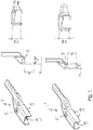
- FIG. 1 shows several schematic views of (a part of) an oscillating arm 1 to be used in a windscreen wiper device of the flat blade type according to the invention.
- a windscreen wiper device of the flat blade type is typically built up of an elastomeric (rubber) wiper blade comprising a central longitudinal groove, wherein a longitudinal strip made of spring band steel is fitted in said longitudinal groove.
- Said strip forms a flexible carrier element for the rubber wiper blade, as it were, which is thus biased in a curved position (the curvature in operative position being that of a windscreen to be wiped).
- an end of said strip and/or an end of said wiper blade is connected on either side of the windscreen wiper device to respective connecting pieces or "end caps”.
- the connecting pieces may be formed as separate constructional elements, which may be form-locked as well as force-locked to both ends of said strip and/or ends of said wiper blade. In the alternative, said connecting pieces may be in one piece with the strip made of spring band steel.
- the windscreen wiper device is furthermore built up of a connecting device 2 of metal for connecting said oscillating wiper arm 1 thereto, with the interposition of a joint part 3 ( figure 2 ).
- the oscillating wiper arm 1 is pivotally connected to the connecting device 2 about a pivot axis near one end.
- FIG 1 two oscillating arms 1,1' are shown, namely an oscillating arm 1 of the first type and an oscillating arm 1' of the second type mutually differing in a distance between legs of an U-shaped cross-section of said oscillating arms 1,1'.
- said distance in the oscillating arm 1 of the first type is 22 mm
- said distance in the oscillating arm 1' of the second type is 19 mm.
- the joint part 3 comprises a resilient tongue 4 extending outwardly, while the oscillating arm 1,1' has said U-shaped cross-section at the location of its connection to said joint part 3, so that the tongue 4 engages in an identically shaped hole 5 provided in a base of said U-shaped cross-section.
- the connecting device 2 with the wiper blade is mounted onto the oscillating arm 1,1' as follows.
- the joint part 3 being already clipped onto the connecting device 2 is pivoted relative to the connecting device 2, so that said joint part 3 can be easily slid on a free end of the oscillating arm 1,1'.
- said oscillating arm 1,1' is connected to a mounting head fixed for rotation to a shaft driven by a small motor.
- the shaft rotates alternately in a clockwise and in a counter-clockwise sense carrying the mounting head into rotation also, which in turn draws said oscillating arm 1,1' into rotation and by means of said connecting device 2 moves said wiper blade.
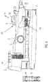
- FIG 2 is depicted a unit consisting of a connecting device 2 and a joint part 3 detachably and pivotally connected thereto according to the invention, wherein said unit is universal part in the sense that it can be used for each and every type of oscillating arm 1,1' with a U-shaped cross-section, that is, for example, for said oscillating arm 1 of the first type on the one hand and for said oscillating arm 1' of the second type on the other hand.
- Said connecting device 2 is particularly welded, soldered, glued or clamped onto two spaced-apart longitudinal strips disposed on opposite sides in longitudinal grooves of the wiper blade.
- said connecting device 2 is connected to the elastomeric (rubber) material of the wiper blade, for example glued or clamped.
- said connecting device 2 comprises two cylindrical protrusions 6 extending outwardly on either side thereof. These protrusions 6 pivotally engage in identically shaped cylindrical recesses 7 in legs 8 of a U-shaped cross-section of said joint part 3. Said protrusions 6 function as bearing surfaces at the location of the pivot axis in order to pivot the joint part 3 (and the oscillating arm 1,1' attached thereto) about said pivot axis near one end of said oscillating arm 1,1'.
- the protrusions 6 are preferably in one piece with said connecting device 2. In the alternative said protrusions 6 are part of a separate pin to be inserted into opposite holes in sidewalls of said connecting device 2 (not shown).
- said resilient tongue 4 of said joint part 3 comprises a first step 9 and a second step 10 as if it were a staircase.
- Said first step 9 is arranged to abut an edge 11 of said hole 5 of said oscillating arm 1 of a first type facing towards a free end thereof.
- Said second step 10 is arranged to abut also said edge 11 of said hole 5 of said oscillating arm 1' of a second type.
- FIGS 4 and 5 sides of the steps 9,10 are indicated with reference numerals 12,13, respectively, which abut the edge 11 of said hole 5 in case an oscillating arm 1 of the first type or an oscillating arm 1' of the second type is used.
- the legs 8 of said U-shaped cross-section of said joint part 3 each comprises an attaching lug 14.
- Said attaching lug 14 is arranged to snappingly engage a corresponding leg of the U-shaped cross-section of said oscillating arms 1,1' of the first type and the second type.
- said attaching lug 14 comprises a protrusion 15 extending laterally inwardly, wherein said attaching lug 14 is hingeable between a downward position ( figure 5 ), wherein said wiper blade can be released from said oscillating arms 1,1' of the first type and the second type, and an upward position ( figure 4 ), wherein said wiper blade can be retained on said oscillating arms 1,1' of the first type and the second type.
- said protrusion 15 is arranged to snap behind said corresponding leg of said U-shaped cross-section of said oscillating arm 1 of the first type.
- said attaching lug 14 also comprises a protrusion 15 extending laterally inwardly.
- said attaching lug 14 can now be pushed in and out in longitudinal direction between a inward position, wherein said wiper blade can be released from said oscillating arm 1 of the second type, and an outward position, wherein said wiper blade can be retained on said oscillating arm 1' of the second type and wherein said protrusion 15 is arranged to snap into a correspondingly shaped recess 18 of said corresponding leg of said U-shaped cross-section of said oscillating arm 1' of the second type.
- each leg of the U-shaped cross-section of said oscillating arms 1,1' of the first type and the second type comprises integral therewith clamping members 19 in form of edges bended inwardly engaging around longitudinal sides of said joint part 3 that face away from each other.
- Figures 9 , 10 and 11 are further views on the interconnection between the joint part 3 and the oscillating arms 1, 1', respectively, wherein corresponding parts have been designated with the same reference numerals.
Landscapes
- Engineering & Computer Science (AREA)
- Mechanical Engineering (AREA)
- Pivots And Pivotal Connections (AREA)
Claims (14)
- Dispositif d'essuie-glace du type à balai plat comprenant un élément de support allongé élastique, ainsi qu'un balai d'essuie-glace allongé en un matériau souple, qui peut être placé en butée contre un pare-brise à essuyer, lequel balai d'essuie-glace comprend au moins une rainure longitudinale, dans laquelle rainure une bande longitudinale de l'élément de support est disposée, lequel dispositif d'essuie-glace comprend un dispositif de liaison (2) pour un bras oscillant (1), dans lequel ledit bras oscillant (1) peut être relié de manière pivotante audit dispositif de liaison (2) autour d'un axe de pivotement à proximité d'une extrémité, avec l'interposition d'une partie d'articulation (3), dans lequel ladite partie d'articulation (3) comprend au moins une languette élastique (4) agencée pour s'engager dans un trou de forme correspondante (5) prévu dans une base d'une section transversale en forme de U dudit bras oscillant, dans lequel ladite languette élastique (4) peut être articulée entre une position vers l'intérieur, dans laquelle ledit balai d'essuie-glace peut être libéré dudit bras oscillant (1), et une position vers l'extérieur, dans laquelle ledit balai d'essuie-glace peut être retenu sur ledit bras oscillant (1), caractérisé en ce que ladite languette élastique comprend un premier gradin (9) et un deuxième gradin (10), dans lequel ledit premier gradin (9) est agencé pour être contigu à un bord dudit trou (5) d'un bras oscillant (1') d'un premier type orienté vers une extrémité libre de celui-ci, dans lequel ledit deuxième gradin (10) est agencé pour être contigu à un bord dudit trou (5) d'un bras oscillant (1") d'un deuxième type orienté vers une extrémité libre de celui-ci, et dans lequel ledit bras oscillant (1') du premier type et ledit bras oscillant (1") du deuxième type diffèrent l'un de l'autre quant à une distance entre les branches de la section transversale en forme de U desdits bras oscillants (1', 1").
- Dispositif d'essuie-glace selon la revendication 1, dans lequel une surface supérieure dudit premier gradin (9) est située plus près dudit balai d'essuie-glace qu'une surface supérieure dudit deuxième gradin (10).
- Dispositif d'essuie-glace selon la revendication 1 ou 2, dans lequel une distance entre les branches de la section transversale en forme de U dudit bras oscillant (1') du premier type est de 22 mm, et dans lequel une distance entre les branches de la section transversale en forme de U dudit bras oscillant (1") du deuxième type est de 19 mm.
- Dispositif d'essuie-glace selon la revendication 1, 2 ou 3, dans lequel ladite partie d'articulation (3) a une section transversale au moins sensiblement en forme de U à un emplacement de sa fixation audit dispositif de liaison, dans lequel au moins une branche de ladite section transversale en forme de U de ladite partie d'articulation (3) comprend une patte de fixation (14), et dans lequel ladite patte de fixation (14) est agencée pour venir en prise par encliquetage avec une branche correspondante de la section transversale en forme de U desdits bras oscillants (1', 1") du premier type et du deuxième type.
- Dispositif d'essuie-glace selon la revendication 4, dans lequel ladite patte de fixation (14) comprend une protubérance (15) s'étendant latéralement vers l'intérieur, et dans lequel ladite patte de fixation (14) peut être articulée entre une position vers le bas, dans laquelle ledit balai d'essuie-glace peut être libéré desdits bras oscillants (1', 1") du premier type et du deuxième type, et une position vers le haut, dans laquelle ledit balai d'essuie-glace peut être retenu sur lesdits bras oscillants (1', 1") du premier type et du deuxième type, et dans lequel ladite protubérance (15) est agencée pour s'encliqueter derrière ladite branche correspondante de ladite section transversale en forme de U desdits bras oscillants (1', 1") du premier type et du deuxième type.
- Dispositif d'essuie-glace selon la revendication 4, dans lequel ladite patte de fixation (14) comprend une protubérance (15) s'étendant latéralement vers l'intérieur, et dans lequel ladite patte de fixation peut être poussée et tirée dans la direction longitudinale entre une position vers l'intérieur, dans laquelle ledit balai d'essuie-glace peut être libéré desdits bras oscillants (1', 1") du premier type et du deuxième type, et une position vers l'extérieur, dans laquelle ledit balai d'essuie-glace peut être retenu sur lesdits bras oscillants (1', 1") du premier type et du deuxième type, et dans lequel ladite protubérance est agencée pour s'encliqueter dans un évidement de forme correspondante de ladite branche correspondante de ladite section transversale en forme de U desdits bras oscillants (1', 1") du premier type et du deuxième type.
- Dispositif d'essuie-glace selon la revendication 5 ou 6, dans lequel ladite partie d'articulation (3) comprend une came (16), et dans lequel ladite came (16) et ladite patte de fixation (14) sont agencées pour retenir longitudinalement entre elles les branches de la section transversale en forme de U dudit bras oscillant (1') du premier type.
- Dispositif d'essuie-glace selon la revendication 5 ou 6, dans lequel ledit dispositif de liaison (2) comprend une came (16), et dans lequel ladite came et ladite patte de fixation sont agencées pour retenir longitudinalement entre elles les branches de la section transversale en forme de U dudit bras oscillant (1') du deuxième type.
- Dispositif d'essuie-glace selon l'une quelconque des revendications 1 à 8 précédentes, dans lequel chaque branche de la section transversale en forme de U desdits bras oscillants (1', 1") du premier type et du deuxième type comprend des éléments de serrage (19) en prise autour des côtés longitudinaux de ladite partie d'articulation (3) qui sont orientés à l'opposé l'un de l'autre.
- Dispositif d'essuie-glace selon l'une quelconque des revendications 1 à 9 précédentes, dans lequel ladite partie d'articulation (3) est constituée d'une matière plastique.
- Dispositif d'essuie-glace selon l'une quelconque des revendications 1 à 10 précédentes, dans lequel ladite partie d'articulation (3) est reliée de manière détachable audit dispositif de liaison (2) en étant en prise de manière pivotante avec les protubérances (6) dudit dispositif de liaison (2) à l'emplacement dudit axe de pivotement dans les évidements (7) prévus dans ladite partie d'articulation (8).
- Dispositif d'essuie-glace selon l'une quelconque des revendications 1 à 11 précédentes, dans lequel ladite partie d'articulation (3) a une section transversale au moins sensiblement en forme de U à l'emplacement de sa fixation audit dispositif de liaison (2), et dans lequel chaque branche de ladite section transversale en forme de U est pourvue d'un évidement (7) prévu coaxialement avec ledit axe de pivotement.
- Véhicule pourvu d'un dispositif d'essuie-glace selon l'une quelconque des revendications 1 à 12 précédentes.
- Procédé pour fabriquer un dispositif d'essuie-glace du type à balai plat comprenant un élément de support allongé élastique, ainsi qu'un balai d'essuie-glace allongé en un matériau souple, qui peut être placé en butée contre un pare-brise à essuyer, lequel balai d'essuie-glace comprend au moins une rainure longitudinale, dans laquelle rainure (3) une bande longitudinale de l'élément de support est disposée, lequel dispositif d'essuie-glace (1) comprend un dispositif de liaison (2) pour un bras oscillant (1), dans lequel ledit bras oscillant (1) peut être relié de manière pivotante audit dispositif de liaison (2) autour d'un axe de pivotement à proximité d'une extrémité, avec l'interposition d'une partie d'articulation (3), dans lequel ladite partie d'articulation (3) comprend au moins une languette élastique (4) agencée pour s'engager dans un trou de forme correspondante (5) prévu dans une base d'une section transversale en forme de U dudit bras oscillant, dans lequel ladite languette élastique peut être articulée entre une position vers l'intérieur, dans laquelle ledit balai d'essuie-glace peut être libéré dudit bras oscillant (1), et une position vers l'extérieur, dans laquelle ledit balai d'essuie-glace peut être retenu sur ledit bras oscillant (1), caractérisé en ce que ladite languette élastique (4) comprend un premier gradin (9) et un deuxième gradin (10), dans lequel ledit premier gradin (9) est agencé pour être contigu à un bord dudit trou (5) d'un bras oscillant (1') d'un premier type orienté vers une extrémité libre de celui-ci, dans lequel ledit deuxième gradin (10) est agencé pour être contigu à un bord dudit trou (5) d'un bras oscillant (1") d'un deuxième type orienté vers une extrémité libre de celui-ci, et dans lequel ledit bras oscillant (1') du premier type et ledit bras oscillant (1") du deuxième type diffèrent l'un de l'autre quant à une distance entre les branches de la section transversale en forme de U desdits bras oscillants (1', 1").
Priority Applications (1)
| Application Number | Priority Date | Filing Date | Title |
|---|---|---|---|
| PL14735946T PL3164304T3 (pl) | 2014-07-03 | 2014-07-03 | Wycieraczka przedniej szyby |
Applications Claiming Priority (1)
| Application Number | Priority Date | Filing Date | Title |
|---|---|---|---|
| PCT/EP2014/064191 WO2016000778A1 (fr) | 2014-07-03 | 2014-07-03 | Dispositif de balai d'essuie-glace |
Publications (2)
| Publication Number | Publication Date |
|---|---|
| EP3164304A1 EP3164304A1 (fr) | 2017-05-10 |
| EP3164304B1 true EP3164304B1 (fr) | 2018-06-13 |
Family
ID=51134084
Family Applications (1)
| Application Number | Title | Priority Date | Filing Date |
|---|---|---|---|
| EP14735946.7A Not-in-force EP3164304B1 (fr) | 2014-07-03 | 2014-07-03 | Dispositif de balai d'essuie-glace |
Country Status (7)
| Country | Link |
|---|---|
| US (1) | US20170136999A1 (fr) |
| EP (1) | EP3164304B1 (fr) |
| KR (1) | KR20170029412A (fr) |
| CN (1) | CN106458162B (fr) |
| MX (1) | MX2016014618A (fr) |
| PL (1) | PL3164304T3 (fr) |
| WO (1) | WO2016000778A1 (fr) |
Cited By (4)
| Publication number | Priority date | Publication date | Assignee | Title |
|---|---|---|---|---|
| US11040705B2 (en) | 2016-05-19 | 2021-06-22 | Pylon Manufacturing Corp. | Windshield wiper connector |
| US11136002B2 (en) | 2012-02-24 | 2021-10-05 | Pylon Manufacturing Corp. | Wiper blade |
| US11370394B2 (en) | 2017-07-28 | 2022-06-28 | Pylon Manufacturing Corporation | Windshield wiper connector and assembly |
| US11465590B2 (en) | 2017-07-28 | 2022-10-11 | Pylon Manufacturing Corporation | Windshield wiper blade assembly |
Families Citing this family (6)
| Publication number | Priority date | Publication date | Assignee | Title |
|---|---|---|---|---|
| FR3037897B1 (fr) * | 2015-06-26 | 2018-11-02 | Valeo Systemes D'essuyage | Adaptateur pour un essuie-glace de vehicule automobile et ensemble comportant un tel adaptateur |
| DE102016225959A1 (de) * | 2016-12-22 | 2018-06-28 | Robert Bosch Gmbh | Wischervorrichtung und Verfahren zur Montage einer Wischervorrichtung |
| FR3065692B1 (fr) * | 2017-04-28 | 2021-01-01 | Valeo Systemes Dessuyage | Adaptateur constitutif d'un systeme d'essuyage |
| EP3668763A1 (fr) * | 2017-08-15 | 2020-06-24 | Federal-Mogul S.A. | Dispositif d'essuie-glace |
| KR20200059217A (ko) | 2017-08-28 | 2020-05-28 | 트리코 벨기에 에스.아. | 윈드스크린 와이퍼 장치 |
| RU202620U1 (ru) * | 2020-09-25 | 2021-03-01 | Першина Светлана Сергеевна | Бескаркасная щетка стеклоочистителя |
Family Cites Families (10)
| Publication number | Priority date | Publication date | Assignee | Title |
|---|---|---|---|---|
| ATE449711T1 (de) * | 1999-10-11 | 2009-12-15 | Federal Mogul Sa | Scheibenwischervorrichtung |
| JP2004106712A (ja) * | 2002-09-19 | 2004-04-08 | Mitsuba Corp | ワイパ装置 |
| DE10347637A1 (de) * | 2003-10-09 | 2005-05-12 | Bosch Gmbh Robert | Vorrichtung zum Verbinden eines Wischblatts mit einem Wischerarm sowie ein Wischblatt, einen Wischerarm und ein entsprechendes Verbindungsstück |
| CA2541641C (fr) * | 2005-04-04 | 2014-02-11 | Trico Products Corporation | Raccord d'essuie-glace et essuie-glace ainsi equipe |
| US9327688B2 (en) * | 2010-05-20 | 2016-05-03 | Federal-Mogul S.A. | Windscreen wiper device |
| CA2880211C (fr) * | 2010-09-15 | 2016-10-25 | Trico Products Corporation | Coupleur universel pour un ensemble essuie-glace a balai a lames |
| DE102010064161A1 (de) * | 2010-12-27 | 2012-06-28 | Robert Bosch Gmbh | Wischblattadapter, insbesondere für eine Kraftfahrzeugwischvorrichtung |
| DE102011053090A1 (de) * | 2011-08-29 | 2013-02-28 | Valeo Systèmes d'Essuyage | Wischblatt für eine Wischeinrichtung eines Kraftfahrzeugs |
| DE102012100778A1 (de) * | 2012-01-31 | 2013-08-01 | Valeo Systèmes d'Essuyage | Scheibenwischvorrichtung zum Reinigen einer Fahrzeugfrontscheibe |
| CN202863398U (zh) * | 2012-09-12 | 2013-04-10 | 东莞鸿益雨刷有限公司 | 雨刷与雨刷杆的装配结构 |
-
2014
- 2014-07-03 CN CN201480079636.8A patent/CN106458162B/zh not_active Expired - Fee Related
- 2014-07-03 PL PL14735946T patent/PL3164304T3/pl unknown
- 2014-07-03 MX MX2016014618A patent/MX2016014618A/es active IP Right Grant
- 2014-07-03 WO PCT/EP2014/064191 patent/WO2016000778A1/fr active Application Filing
- 2014-07-03 KR KR1020167032253A patent/KR20170029412A/ko active IP Right Grant
- 2014-07-03 US US15/321,941 patent/US20170136999A1/en not_active Abandoned
- 2014-07-03 EP EP14735946.7A patent/EP3164304B1/fr not_active Not-in-force
Non-Patent Citations (1)
| Title |
|---|
| None * |
Cited By (4)
| Publication number | Priority date | Publication date | Assignee | Title |
|---|---|---|---|---|
| US11136002B2 (en) | 2012-02-24 | 2021-10-05 | Pylon Manufacturing Corp. | Wiper blade |
| US11040705B2 (en) | 2016-05-19 | 2021-06-22 | Pylon Manufacturing Corp. | Windshield wiper connector |
| US11370394B2 (en) | 2017-07-28 | 2022-06-28 | Pylon Manufacturing Corporation | Windshield wiper connector and assembly |
| US11465590B2 (en) | 2017-07-28 | 2022-10-11 | Pylon Manufacturing Corporation | Windshield wiper blade assembly |
Also Published As
| Publication number | Publication date |
|---|---|
| PL3164304T3 (pl) | 2018-10-31 |
| MX2016014618A (es) | 2017-02-23 |
| WO2016000778A1 (fr) | 2016-01-07 |
| EP3164304A1 (fr) | 2017-05-10 |
| CN106458162A (zh) | 2017-02-22 |
| CN106458162B (zh) | 2019-06-07 |
| US20170136999A1 (en) | 2017-05-18 |
| KR20170029412A (ko) | 2017-03-15 |
Similar Documents
| Publication | Publication Date | Title |
|---|---|---|
| EP3164304B1 (fr) | Dispositif de balai d'essuie-glace | |
| EP1876073B1 (fr) | Dispositif d'essuie-glace | |
| EP1847425B1 (fr) | Dispositif d'essuie-glace | |
| EP1854685B1 (fr) | Dispositif d'essuie-glace | |
| EP1795406B1 (fr) | Dispositif d'essuie-glace | |
| EP1876074B1 (fr) | Dispositif d'essuie-glace | |
| EP2670637B1 (fr) | Dispositif d'essuie-glace | |
| EP3416858B1 (fr) | Dispositif d'essuie-glace | |
| EP3164303B1 (fr) | Dispositif d'essuie-glace | |
| WO2012065639A1 (fr) | Dispositif d'essuie-glace | |
| EP3169566B1 (fr) | Essuie-glace | |
| EP2750939B1 (fr) | Dispositif de balai d'essuie-glace | |
| EP2621772B1 (fr) | Dispositif essuie-glace | |
| EP2593340B1 (fr) | Dispositif d'essuie-glace | |
| EP2585344B1 (fr) | Dispositif d'essuie-glace | |
| US20200254977A1 (en) | A windscreen wiper device | |
| EP3592614A1 (fr) | Dispositif d'essuie-glace | |
| CN110678365A (zh) | 风挡雨刷装置 |
Legal Events
| Date | Code | Title | Description |
|---|---|---|---|
| PUAI | Public reference made under article 153(3) epc to a published international application that has entered the european phase |
Free format text: ORIGINAL CODE: 0009012 |
|
| 17P | Request for examination filed |
Effective date: 20161213 |
|
| AK | Designated contracting states |
Kind code of ref document: A1 Designated state(s): AL AT BE BG CH CY CZ DE DK EE ES FI FR GB GR HR HU IE IS IT LI LT LU LV MC MK MT NL NO PL PT RO RS SE SI SK SM TR |
|
| AX | Request for extension of the european patent |
Extension state: BA ME |
|
| DAX | Request for extension of the european patent (deleted) | ||
| GRAP | Despatch of communication of intention to grant a patent |
Free format text: ORIGINAL CODE: EPIDOSNIGR1 |
|
| INTG | Intention to grant announced |
Effective date: 20180215 |
|
| GRAS | Grant fee paid |
Free format text: ORIGINAL CODE: EPIDOSNIGR3 |
|
| GRAA | (expected) grant |
Free format text: ORIGINAL CODE: 0009210 |
|
| AK | Designated contracting states |
Kind code of ref document: B1 Designated state(s): AL AT BE BG CH CY CZ DE DK EE ES FI FR GB GR HR HU IE IS IT LI LT LU LV MC MK MT NL NO PL PT RO RS SE SI SK SM TR |
|
| REG | Reference to a national code |
Ref country code: GB Ref legal event code: FG4D |
|
| REG | Reference to a national code |
Ref country code: CH Ref legal event code: EP Ref country code: AT Ref legal event code: REF Ref document number: 1008168 Country of ref document: AT Kind code of ref document: T Effective date: 20180615 |
|
| REG | Reference to a national code |
Ref country code: IE Ref legal event code: FG4D |
|
| REG | Reference to a national code |
Ref country code: DE Ref legal event code: R096 Ref document number: 602014026974 Country of ref document: DE |
|
| REG | Reference to a national code |
Ref country code: FR Ref legal event code: PLFP Year of fee payment: 5 |
|
| REG | Reference to a national code |
Ref country code: NL Ref legal event code: MP Effective date: 20180613 |
|
| REG | Reference to a national code |
Ref country code: LT Ref legal event code: MG4D |
|
| PG25 | Lapsed in a contracting state [announced via postgrant information from national office to epo] |
Ref country code: LT Free format text: LAPSE BECAUSE OF FAILURE TO SUBMIT A TRANSLATION OF THE DESCRIPTION OR TO PAY THE FEE WITHIN THE PRESCRIBED TIME-LIMIT Effective date: 20180613 Ref country code: CY Free format text: LAPSE BECAUSE OF FAILURE TO SUBMIT A TRANSLATION OF THE DESCRIPTION OR TO PAY THE FEE WITHIN THE PRESCRIBED TIME-LIMIT Effective date: 20180613 Ref country code: NO Free format text: LAPSE BECAUSE OF FAILURE TO SUBMIT A TRANSLATION OF THE DESCRIPTION OR TO PAY THE FEE WITHIN THE PRESCRIBED TIME-LIMIT Effective date: 20180913 Ref country code: FI Free format text: LAPSE BECAUSE OF FAILURE TO SUBMIT A TRANSLATION OF THE DESCRIPTION OR TO PAY THE FEE WITHIN THE PRESCRIBED TIME-LIMIT Effective date: 20180613 Ref country code: BG Free format text: LAPSE BECAUSE OF FAILURE TO SUBMIT A TRANSLATION OF THE DESCRIPTION OR TO PAY THE FEE WITHIN THE PRESCRIBED TIME-LIMIT Effective date: 20180913 Ref country code: SE Free format text: LAPSE BECAUSE OF FAILURE TO SUBMIT A TRANSLATION OF THE DESCRIPTION OR TO PAY THE FEE WITHIN THE PRESCRIBED TIME-LIMIT Effective date: 20180613 |
|
| PG25 | Lapsed in a contracting state [announced via postgrant information from national office to epo] |
Ref country code: RS Free format text: LAPSE BECAUSE OF FAILURE TO SUBMIT A TRANSLATION OF THE DESCRIPTION OR TO PAY THE FEE WITHIN THE PRESCRIBED TIME-LIMIT Effective date: 20180613 Ref country code: GR Free format text: LAPSE BECAUSE OF FAILURE TO SUBMIT A TRANSLATION OF THE DESCRIPTION OR TO PAY THE FEE WITHIN THE PRESCRIBED TIME-LIMIT Effective date: 20180914 Ref country code: HR Free format text: LAPSE BECAUSE OF FAILURE TO SUBMIT A TRANSLATION OF THE DESCRIPTION OR TO PAY THE FEE WITHIN THE PRESCRIBED TIME-LIMIT Effective date: 20180613 Ref country code: LV Free format text: LAPSE BECAUSE OF FAILURE TO SUBMIT A TRANSLATION OF THE DESCRIPTION OR TO PAY THE FEE WITHIN THE PRESCRIBED TIME-LIMIT Effective date: 20180613 |
|
| REG | Reference to a national code |
Ref country code: AT Ref legal event code: MK05 Ref document number: 1008168 Country of ref document: AT Kind code of ref document: T Effective date: 20180613 |
|
| PG25 | Lapsed in a contracting state [announced via postgrant information from national office to epo] |
Ref country code: NL Free format text: LAPSE BECAUSE OF FAILURE TO SUBMIT A TRANSLATION OF THE DESCRIPTION OR TO PAY THE FEE WITHIN THE PRESCRIBED TIME-LIMIT Effective date: 20180613 |
|
| PG25 | Lapsed in a contracting state [announced via postgrant information from national office to epo] |
Ref country code: SK Free format text: LAPSE BECAUSE OF FAILURE TO SUBMIT A TRANSLATION OF THE DESCRIPTION OR TO PAY THE FEE WITHIN THE PRESCRIBED TIME-LIMIT Effective date: 20180613 Ref country code: RO Free format text: LAPSE BECAUSE OF FAILURE TO SUBMIT A TRANSLATION OF THE DESCRIPTION OR TO PAY THE FEE WITHIN THE PRESCRIBED TIME-LIMIT Effective date: 20180613 Ref country code: IS Free format text: LAPSE BECAUSE OF FAILURE TO SUBMIT A TRANSLATION OF THE DESCRIPTION OR TO PAY THE FEE WITHIN THE PRESCRIBED TIME-LIMIT Effective date: 20181013 Ref country code: AT Free format text: LAPSE BECAUSE OF FAILURE TO SUBMIT A TRANSLATION OF THE DESCRIPTION OR TO PAY THE FEE WITHIN THE PRESCRIBED TIME-LIMIT Effective date: 20180613 Ref country code: EE Free format text: LAPSE BECAUSE OF FAILURE TO SUBMIT A TRANSLATION OF THE DESCRIPTION OR TO PAY THE FEE WITHIN THE PRESCRIBED TIME-LIMIT Effective date: 20180613 |
|
| PG25 | Lapsed in a contracting state [announced via postgrant information from national office to epo] |
Ref country code: SM Free format text: LAPSE BECAUSE OF FAILURE TO SUBMIT A TRANSLATION OF THE DESCRIPTION OR TO PAY THE FEE WITHIN THE PRESCRIBED TIME-LIMIT Effective date: 20180613 Ref country code: ES Free format text: LAPSE BECAUSE OF FAILURE TO SUBMIT A TRANSLATION OF THE DESCRIPTION OR TO PAY THE FEE WITHIN THE PRESCRIBED TIME-LIMIT Effective date: 20180613 |
|
| REG | Reference to a national code |
Ref country code: CH Ref legal event code: PL |
|
| REG | Reference to a national code |
Ref country code: DE Ref legal event code: R097 Ref document number: 602014026974 Country of ref document: DE |
|
| PG25 | Lapsed in a contracting state [announced via postgrant information from national office to epo] |
Ref country code: MC Free format text: LAPSE BECAUSE OF FAILURE TO SUBMIT A TRANSLATION OF THE DESCRIPTION OR TO PAY THE FEE WITHIN THE PRESCRIBED TIME-LIMIT Effective date: 20180613 Ref country code: LU Free format text: LAPSE BECAUSE OF NON-PAYMENT OF DUE FEES Effective date: 20180703 |
|
| REG | Reference to a national code |
Ref country code: IE Ref legal event code: MM4A |
|
| PLBE | No opposition filed within time limit |
Free format text: ORIGINAL CODE: 0009261 |
|
| STAA | Information on the status of an ep patent application or granted ep patent |
Free format text: STATUS: NO OPPOSITION FILED WITHIN TIME LIMIT |
|
| PG25 | Lapsed in a contracting state [announced via postgrant information from national office to epo] |
Ref country code: CH Free format text: LAPSE BECAUSE OF NON-PAYMENT OF DUE FEES Effective date: 20180731 Ref country code: IE Free format text: LAPSE BECAUSE OF NON-PAYMENT OF DUE FEES Effective date: 20180703 Ref country code: LI Free format text: LAPSE BECAUSE OF NON-PAYMENT OF DUE FEES Effective date: 20180731 |
|
| 26N | No opposition filed |
Effective date: 20190314 |
|
| GBPC | Gb: european patent ceased through non-payment of renewal fee |
Effective date: 20180913 |
|
| PG25 | Lapsed in a contracting state [announced via postgrant information from national office to epo] |
Ref country code: DK Free format text: LAPSE BECAUSE OF FAILURE TO SUBMIT A TRANSLATION OF THE DESCRIPTION OR TO PAY THE FEE WITHIN THE PRESCRIBED TIME-LIMIT Effective date: 20180613 Ref country code: SI Free format text: LAPSE BECAUSE OF FAILURE TO SUBMIT A TRANSLATION OF THE DESCRIPTION OR TO PAY THE FEE WITHIN THE PRESCRIBED TIME-LIMIT Effective date: 20180613 |
|
| PGFP | Annual fee paid to national office [announced via postgrant information from national office to epo] |
Ref country code: PL Payment date: 20190627 Year of fee payment: 6 Ref country code: CZ Payment date: 20190627 Year of fee payment: 6 |
|
| PG25 | Lapsed in a contracting state [announced via postgrant information from national office to epo] |
Ref country code: GB Free format text: LAPSE BECAUSE OF NON-PAYMENT OF DUE FEES Effective date: 20180913 |
|
| PGFP | Annual fee paid to national office [announced via postgrant information from national office to epo] |
Ref country code: FR Payment date: 20190711 Year of fee payment: 6 Ref country code: IT Payment date: 20190719 Year of fee payment: 6 Ref country code: DE Payment date: 20190702 Year of fee payment: 6 |
|
| PG25 | Lapsed in a contracting state [announced via postgrant information from national office to epo] |
Ref country code: AL Free format text: LAPSE BECAUSE OF FAILURE TO SUBMIT A TRANSLATION OF THE DESCRIPTION OR TO PAY THE FEE WITHIN THE PRESCRIBED TIME-LIMIT Effective date: 20180613 |
|
| PGFP | Annual fee paid to national office [announced via postgrant information from national office to epo] |
Ref country code: BE Payment date: 20190716 Year of fee payment: 6 |
|
| PG25 | Lapsed in a contracting state [announced via postgrant information from national office to epo] |
Ref country code: MT Free format text: LAPSE BECAUSE OF NON-PAYMENT OF DUE FEES Effective date: 20180703 |
|
| PG25 | Lapsed in a contracting state [announced via postgrant information from national office to epo] |
Ref country code: PT Free format text: LAPSE BECAUSE OF FAILURE TO SUBMIT A TRANSLATION OF THE DESCRIPTION OR TO PAY THE FEE WITHIN THE PRESCRIBED TIME-LIMIT Effective date: 20180613 |
|
| PG25 | Lapsed in a contracting state [announced via postgrant information from national office to epo] |
Ref country code: HU Free format text: LAPSE BECAUSE OF FAILURE TO SUBMIT A TRANSLATION OF THE DESCRIPTION OR TO PAY THE FEE WITHIN THE PRESCRIBED TIME-LIMIT; INVALID AB INITIO Effective date: 20140703 Ref country code: MK Free format text: LAPSE BECAUSE OF NON-PAYMENT OF DUE FEES Effective date: 20180613 |
|
| PG25 | Lapsed in a contracting state [announced via postgrant information from national office to epo] |
Ref country code: CZ Free format text: LAPSE BECAUSE OF NON-PAYMENT OF DUE FEES Effective date: 20200703 |
|
| REG | Reference to a national code |
Ref country code: DE Ref legal event code: R119 Ref document number: 602014026974 Country of ref document: DE |
|
| REG | Reference to a national code |
Ref country code: BE Ref legal event code: MM Effective date: 20200731 |
|
| PG25 | Lapsed in a contracting state [announced via postgrant information from national office to epo] |
Ref country code: FR Free format text: LAPSE BECAUSE OF NON-PAYMENT OF DUE FEES Effective date: 20200731 |
|
| PG25 | Lapsed in a contracting state [announced via postgrant information from national office to epo] |
Ref country code: BE Free format text: LAPSE BECAUSE OF NON-PAYMENT OF DUE FEES Effective date: 20200731 Ref country code: DE Free format text: LAPSE BECAUSE OF NON-PAYMENT OF DUE FEES Effective date: 20210202 |
|
| PG25 | Lapsed in a contracting state [announced via postgrant information from national office to epo] |
Ref country code: IT Free format text: LAPSE BECAUSE OF NON-PAYMENT OF DUE FEES Effective date: 20200703 |
|
| PG25 | Lapsed in a contracting state [announced via postgrant information from national office to epo] |
Ref country code: TR Free format text: LAPSE BECAUSE OF NON-PAYMENT OF DUE FEES Effective date: 20200703 |
|
| PG25 | Lapsed in a contracting state [announced via postgrant information from national office to epo] |
Ref country code: PL Free format text: LAPSE BECAUSE OF NON-PAYMENT OF DUE FEES Effective date: 20200703 |