EP3163659A1 - Air electrode, metal air battery, and air electrode material - Google Patents
Air electrode, metal air battery, and air electrode material Download PDFInfo
- Publication number
- EP3163659A1 EP3163659A1 EP16814537.3A EP16814537A EP3163659A1 EP 3163659 A1 EP3163659 A1 EP 3163659A1 EP 16814537 A EP16814537 A EP 16814537A EP 3163659 A1 EP3163659 A1 EP 3163659A1
- Authority
- EP
- European Patent Office
- Prior art keywords
- air electrode
- air
- cnt
- ldh
- particles
- Prior art date
- Legal status (The legal status is an assumption and is not a legal conclusion. Google has not performed a legal analysis and makes no representation as to the accuracy of the status listed.)
- Granted
Links
Images


Classifications
-
- H—ELECTRICITY
- H01—ELECTRIC ELEMENTS
- H01M—PROCESSES OR MEANS, e.g. BATTERIES, FOR THE DIRECT CONVERSION OF CHEMICAL ENERGY INTO ELECTRICAL ENERGY
- H01M12/00—Hybrid cells; Manufacture thereof
- H01M12/08—Hybrid cells; Manufacture thereof composed of a half-cell of a fuel-cell type and a half-cell of the secondary-cell type
-
- H—ELECTRICITY
- H01—ELECTRIC ELEMENTS
- H01M—PROCESSES OR MEANS, e.g. BATTERIES, FOR THE DIRECT CONVERSION OF CHEMICAL ENERGY INTO ELECTRICAL ENERGY
- H01M12/00—Hybrid cells; Manufacture thereof
- H01M12/04—Hybrid cells; Manufacture thereof composed of a half-cell of the fuel-cell type and of a half-cell of the primary-cell type
- H01M12/06—Hybrid cells; Manufacture thereof composed of a half-cell of the fuel-cell type and of a half-cell of the primary-cell type with one metallic and one gaseous electrode
-
- H—ELECTRICITY
- H01—ELECTRIC ELEMENTS
- H01M—PROCESSES OR MEANS, e.g. BATTERIES, FOR THE DIRECT CONVERSION OF CHEMICAL ENERGY INTO ELECTRICAL ENERGY
- H01M4/00—Electrodes
- H01M4/86—Inert electrodes with catalytic activity, e.g. for fuel cells
-
- H—ELECTRICITY
- H01—ELECTRIC ELEMENTS
- H01M—PROCESSES OR MEANS, e.g. BATTERIES, FOR THE DIRECT CONVERSION OF CHEMICAL ENERGY INTO ELECTRICAL ENERGY
- H01M4/00—Electrodes
- H01M4/86—Inert electrodes with catalytic activity, e.g. for fuel cells
- H01M4/8605—Porous electrodes
- H01M4/8615—Bifunctional electrodes for rechargeable cells
-
- H—ELECTRICITY
- H01—ELECTRIC ELEMENTS
- H01M—PROCESSES OR MEANS, e.g. BATTERIES, FOR THE DIRECT CONVERSION OF CHEMICAL ENERGY INTO ELECTRICAL ENERGY
- H01M4/00—Electrodes
- H01M4/86—Inert electrodes with catalytic activity, e.g. for fuel cells
- H01M4/8647—Inert electrodes with catalytic activity, e.g. for fuel cells consisting of more than one material, e.g. consisting of composites
- H01M4/8652—Inert electrodes with catalytic activity, e.g. for fuel cells consisting of more than one material, e.g. consisting of composites as mixture
-
- H—ELECTRICITY
- H01—ELECTRIC ELEMENTS
- H01M—PROCESSES OR MEANS, e.g. BATTERIES, FOR THE DIRECT CONVERSION OF CHEMICAL ENERGY INTO ELECTRICAL ENERGY
- H01M4/00—Electrodes
- H01M4/86—Inert electrodes with catalytic activity, e.g. for fuel cells
- H01M4/8663—Selection of inactive substances as ingredients for catalytic active masses, e.g. binders, fillers
- H01M4/8673—Electrically conductive fillers
-
- H—ELECTRICITY
- H01—ELECTRIC ELEMENTS
- H01M—PROCESSES OR MEANS, e.g. BATTERIES, FOR THE DIRECT CONVERSION OF CHEMICAL ENERGY INTO ELECTRICAL ENERGY
- H01M4/00—Electrodes
- H01M4/86—Inert electrodes with catalytic activity, e.g. for fuel cells
- H01M4/90—Selection of catalytic material
- H01M4/9016—Oxides, hydroxides or oxygenated metallic salts
-
- H—ELECTRICITY
- H01—ELECTRIC ELEMENTS
- H01M—PROCESSES OR MEANS, e.g. BATTERIES, FOR THE DIRECT CONVERSION OF CHEMICAL ENERGY INTO ELECTRICAL ENERGY
- H01M4/00—Electrodes
- H01M4/86—Inert electrodes with catalytic activity, e.g. for fuel cells
- H01M4/96—Carbon-based electrodes
-
- H—ELECTRICITY
- H01—ELECTRIC ELEMENTS
- H01M—PROCESSES OR MEANS, e.g. BATTERIES, FOR THE DIRECT CONVERSION OF CHEMICAL ENERGY INTO ELECTRICAL ENERGY
- H01M2300/00—Electrolytes
- H01M2300/0017—Non-aqueous electrolytes
- H01M2300/0065—Solid electrolytes
- H01M2300/0068—Solid electrolytes inorganic
-
- Y—GENERAL TAGGING OF NEW TECHNOLOGICAL DEVELOPMENTS; GENERAL TAGGING OF CROSS-SECTIONAL TECHNOLOGIES SPANNING OVER SEVERAL SECTIONS OF THE IPC; TECHNICAL SUBJECTS COVERED BY FORMER USPC CROSS-REFERENCE ART COLLECTIONS [XRACs] AND DIGESTS
- Y02—TECHNOLOGIES OR APPLICATIONS FOR MITIGATION OR ADAPTATION AGAINST CLIMATE CHANGE
- Y02E—REDUCTION OF GREENHOUSE GAS [GHG] EMISSIONS, RELATED TO ENERGY GENERATION, TRANSMISSION OR DISTRIBUTION
- Y02E60/00—Enabling technologies; Technologies with a potential or indirect contribution to GHG emissions mitigation
- Y02E60/10—Energy storage using batteries
Definitions
- the present invention relates to an air electrode, a metal-air battery, an air electrode material, and a method of manufacturing an air electrode material.
- An air electrode for a metal-air battery typically comprises an electron conductive material as a principal component, and includes a layered double hydroxide and an adhesive as a secondary component (for example, reference is made to Patent Literature 1).
- a carbon material or the like is used as the electron conductive material.
- the adhesive includes use of various types of organic binders such as polyvinylidene fluoride, polytetrafluoroethylene, and a styrene/butadiene rubber, or the like.
- Patent Literature 1 Japanese Patent Application Laid-Open No. 2012-43567
- the present invention is proposed in light of the above insight, and has the object of providing an air electrode, a metal-air battery and an air electrode material that exhibit enhanced characteristics.
- the air electrode of the present invention is an air electrode that is used in a metal-air battery, and includes a plurality of carbon nanotubes (CNT) and a plurality of layered double hydroxide particles (LDH).
- the plurality of layered double hydroxide particles are supported on the plurality of carbon nanotubes.
- the present invention provides an air electrode, a metal-air battery and an air electrode material that exhibit enhanced characteristics.
- a metal-air battery is a concept that includes configurations such as a zinc-air secondary battery or a lithium-air secondary battery or the like.
- the present embodiment describes a zinc-air secondary battery as an example of a metal-air battery.
- FIG. 1 is a cross sectional view that schematically illustrates a configuration of a zinc-air secondary battery 10.
- the zinc-air secondary battery 10 includes an air electrode 12, an hydroxide ion conductive separator 14, a negative electrode 16 immersed in an electrolyte solution, a positive electrode current collecting body 18, and a housing 20.
- the air electrode 12 functions as a positive electrode that causes reactions that produce and/or reduce O 2 .
- the air electrode 12 is disposed on the hydroxide ion conductive separator 14.
- the air electrode 12 includes a first principal surface 12S and a second principal surface 12T.
- the air electrode 12 comes into contact with the hydroxide ion conductive separator 14 on the first principal surface 12S.
- the air electrode 12 comes into contact with the positive electrode current collecting body 18 on the second principal surface 12T.
- the thickness of the air electrode 12 may be 1 to 100 ⁇ m, preferably may be 1 to 75 ⁇ m, more preferably may be 1 to 50 ⁇ m, and still more preferably may be 1 to 30 ⁇ m. In this manner, the surface area of the three phase interface of the gaseous phase, the electron conductive phase and the hydroxide ion conductive phase can be ensured to thereby maintain the catalytic reactivity of the air electrode 12.
- the air electrode 12 includes carbon nanotubes (abbreviated below to “CNT”) and layered double hydroxide particles (abbreviated below to “LDH”).
- CNT carbon nanotubes
- LDH layered double hydroxide particles
- CNT is configured from a fibrous carbon material forming a hexagonal lattice structure of graphene into a cylindrical shape.
- CNT may be configured as a single-walled carbon nanotube or as a multi-walled carbon nanotube. Both ends of the CNT may be closed or open.
- CNT functions as an inorganic binder. CNT maintains the shape of the air electrode 12 by binding the LDH. CNT functions as an oxygen reducing/producing catalyst. The catalytic reactivity of the air electrode 12 can be enhanced by including CNT in the air electrode 12. CNT functions as an electron conductive body. The electron conductivity of the air electrode 12 can be enhanced by including CNT in the air electrode 12.
- CNT preferably is configured inside the air electrode 12 in an untangled state rather than in a bundled configuration. In this manner, LDH can be bound efficiently. However, a portion of CNT may be present in a bundled configuration within the air electrode 12.
- LDH exhibits hydroxide ion conductivity.
- LDH is expressed by the general formula M 2+ 1-x M 3+ x (OH) 2 A n- x/n ⁇ mH 2 O (wherein M 2+ is one or more types of bivalent positive ion, M 3+ is one or more types of trivalent positive ion, A n- is an n valent negative ion, n is an integer of at least 1, x is 0.1 to 0.4, and m is greater than or equal to 0).
- M 2+ may include Ni 2+ , Mg 2+ , Ca 2+ , M n 2+ , Fe 2+ , Co 2+ , Cu 2+ , Zn 2+ .
- M 3+ may include Fe 3+ , Al 3+ , Co 3+ , Cr 3+ , In 3+ .
- a n- may include NO 3- , CO 3 2- , SO 4 2- , OH - , Cl - , I - , Br - , F - .
- an Mg-Al configuration of LDH is preferred in which M 2+ is Mg 2+ , and M 3+ may includes Al 3+ .
- the CNT content amount in the air electrode 12 is greater than or equal to 0.1 volume % to less than or equal to 40 volume %. In this manner, CNT that functions as an oxygen reducing/producing catalyst and an electron conductive body can be caused to function as an inorganic binder. Therefore the air electrode 12 does not require the inclusion of an organic binder to contribute in some manner to the characteristics (electron conductivity or catalytic reactivity), and therefore the characteristics of the air electrode 12 can be conspicuously enhanced when compared to a configuration in which LDH is bound by use of an organic binder.
- the content amount of CNT in the air electrode 12 is preferably greater than or equal to 0.1 volume % to less than or equal to 30 volume %, and more preferably greater than or equal to 0.1 volume % to less than or equal to 20 volume %.
- the content amount of LDH in the air electrode 12 may be configured as greater than or equal to 60 volume % to less than or equal to 99.9 volume %.
- the content amount of LDH in the air electrode 12 is preferably greater than or equal to 60 volume % to less than or equal to 90 volume %, and still more preferably the content amount of LDH in the air electrode 12 may be configured as greater than or equal to 60 volume % to less than or equal to 70 volume %.
- the volume ratio of CNT to LDH in the air electrode 12 (CNT volume ⁇ LDH volume) is preferably at least 0.001. In this manner, LDH can be generally enclosed in CNT and it is possible to further enhance the electron conductivity of the air electrode 12.
- the volume ratio of CNT to LDH in the air electrode 12 is preferably less than or equal to 1. In this manner, it is possible to further enhance the hydroxide ion conductivity of the air electrode 12.
- the air electrode 12 may include a perovskite oxide that is expressed by the general formula ABO 3- ⁇ (wherein ⁇ ⁇ 0.4). This type of perovskite oxide preferably exhibits electron conductivity, but is not required to exhibit electron conductivity.
- the perovskite oxide preferably functions as an oxygen reducing/producing catalyst.
- the perovskite oxide is preferably a perovskite oxide that is expressed by the general formula ABO 3- ⁇ (wherein ⁇ ⁇ 0.4), that includes at least La at the A site and that includes at least Ni, Fe and Cu at the B site.
- This type of perovskite oxide is expressed by the composition formula LaNi 1-x-y Cu x FC y O 3- ⁇ (x > 0, y> 0, x+y ⁇ 1,0 ⁇ ⁇ ⁇ 0. 4).
- LNFCu perovskite oxide that is expressed by the composition formula LaNi 1-x-y Cu x Fe y O 3- ⁇
- x ⁇ 0.5 it is preferred that x ⁇ 0.5, further preferred that 0.0 1 ⁇ x ⁇ 0.5, and still more preferred that 0.05 ⁇ x ⁇ 0.3. It is possible to enhance the electron conductivity, the coefficient of thermal expansion and the catalytic reactivity of the air electrode 12 by adjusting x and y to the above range.
- LNFCu is preferably configured by a single perovskite phase. In this manner, it is possible to further enhance the electron conductivity and the catalytic reactivity of the air electrode 12
- the perovskite oxide may contain LNFCu as a principal component.
- the term such that composition P "contains as a principal component" substance Q means that substance Q occupies greater than or equal to 70 wt%, and preferably occupies greater than or equal to 90 wt% of the total of composition P.
- the content amount of the perovskite oxide in the air electrode 12 may be configured as greater than or equal to 0.1 volume % to less than or equal to 50 volume %.
- the content amount of the perovskite oxide in the air electrode 12 is preferably greater than or equal to 0.1 volume % to less than or equal to 40 volume %.
- the volume ratio of CNT relative to the perovskite oxide in the air electrode 12 (CNT volume ⁇ perovskite oxide volume) may be configured as greater than or equal to 0.002 to less than or equal to 400, and is preferably greater than or equal to 0.02 to less than or equal to 40.
- the air electrode 12 may contain a minute quantity of an organic binder.
- the content amount of the organic binder in the air electrode is preferably less than or equal to 10 volume %.
- a thermoplastic resin or thermos-curing resin may be used as the organic binder, there is no particular limitation in this regard.
- organic binder examples include
- the binder is not particularly well limited and a thermoplastic resin or a thermosetting resin, preferred examples include carboxymethyl cellulose (CMC), polyethylene, polypropylene, polytetrafluoroethylene (PTFE), polyvinylidene fluoride (PVDF), styrene-butadiene rubber, tetrafluoroethylene-hexafluoroethylene copolymer, tetrafluoroethylene-hexafluoropropylene copolymer (FEP), tetrafluoroethylene-perfluoroalkyl vinyl ether copolymer (PFA), vinylidene fluoride-hexafluoropropylene copolymer, vinylidene fluoride-chlorotrifluoroethylene copolymer, an ethylene-tetrafluoroethylene copolymer (ETFE resin), polychlorotrifluoroethylene (PCTFE), vinylidene fluoride-pentafluoro propylene copolymer,
- the hydroxide ion conductive separator 14 is disposed between the air electrode 12 and the negative electrode 16.
- the hydroxide ion conductive separator 14 makes contact with the first principal surface 12S of the air electrode 12.
- the hydroxide ion conductive separator 14 is configured from a material that exhibits selective permeability to the hydroxide ions that are produced and consumed in the air electrode 12.
- the hydroxide ion conductive separator 14 preferably does not allow passage of alkali metal ions in the electrolyte solution or undesirable substances (such as carbon dioxide or the like) other than oxygen that is contained in the air.
- Such materials include compact ceramics that are inorganic solid electrolytes that exhibit hydroxide ion conductivity.
- An inorganic solid electrolyte that exhibits hydroxide ion conductivity is preferably LDH that has been compacted by use of a solidifying method (for example, a hydrothermal solidifying method) that that is expressed by the general formula M 2+ 1-x M 3+ x (OH) 2 A n- x/n ⁇ mH 2 O.
- a solidifying method for example, a hydrothermal solidifying method
- An inorganic solid electrolyte that exhibits hydroxide ion conductivity may include use of a configuration that has at least one type of basic composition selected from the group consisting of NaCo 2 O 4 , LaFe 3 Sr 3 O 10 , Bi 4 Sr 14 Fe 24 O 56, NaLaTiO 4 , RbLaNb 2 O 7 , KLaNb 2 O 7 , and Sr 4 CO 1 . 6 Ti 1.4 O 8 (OH) 2 ⁇ x H 2 O.
- the above inorganic solid electrolytes have been disclosed in PCT Laid Open Application 2011/108526 as a solid electrolyte that exhibits hydroxide ion conductivity for used in relation to a fuel cell. It is possible to suppress deterioration of the electrolyte solution resulting from production of carbon ions as a result of use of a solid electrolyte that exhibits hydroxide ion conductivity as the hydroxide ion conductive separator 14, and to suppress production of short circuiting between the positive and negative electrodes through the hydroxide ion conductive separator 14 as a result of zinc dendrites produced during charging.
- the hydroxide ion conductive separator 14 may be configured as a composite body including a particle group containing the inorganic solid electrolyte that exhibits hydroxide ion conductivity and a component that assists in the curing or compaction of the particle group.
- the hydroxide ion conductive separator 14 may be also configured as a composite body including an open-pore porous body that is used as a substrate and an inorganic solid electrolyte that is deposited or grown in the pores to thereby embed the pores of the porous body.
- the porous body may be configured as an insulating material such as a porous sheet or the like that is configured from a resin foam or a fibrous material, or a ceramic such as alumina, zirconia, or the like.
- the relative density of the hydroxide ion conductive separator 14 as calculated by use of an Archimedes method is preferably greater than or equal to 88%, more preferably greater than or equal to 90%, and still more preferably greater than or equal to 94%.
- the thickness of the hydroxide ion conductive separator 14 may be configured as 0.001 to 0.05 mm, preferably 0.001 to 0.01 mm, and more preferably 0.001 to 0.005 mm.
- a higher hydroxide ion conductivity in the hydroxide ion conductive separator 14 is preferred, and typically exhibits a conductivity of 1 ⁇ 10 -4 ⁇ 1 ⁇ 10 -1 S/m(1 ⁇ 10 -3 ⁇ 1 mS/cm), and more typically 1 ⁇ 10 -4 ⁇ 1 ⁇ 10 -2 S/m(1 ⁇ 10 -3 ⁇ 1 ⁇ 10 -1 mS/cm).
- the negative electrode 16 is disposed on the opposite side of the air electrode 12 to thereby sandwich the hydroxide ion conductive separator 14.
- the negative electrode 16 is immersed in an electrolyte solution.
- the negative electrode 16 includes zinc or a zinc alloy that functions as a negative electrode active material.
- a configuration as a particle, plate or gel is possible with a particle or gel configuration being preferably in light of reaction rate.
- the particle diameter of a particle-shaped negative electrode 16 is preferably 30 to 350 ⁇ m.
- a gel-shaped negative electrode 16 is preferably shaped into a gel configuration by mixing and agitating a non-mercury zinc alloy powder having a particle diameter of 100 to 300 ⁇ m, an alkali electrolyte solution and a thickener (gelling agent).
- the zinc alloy includes mercury alloys or non-mercury alloys with magnesium, aluminum, lithium, bismuth, indium, lead, or the like.
- the zinc alloy is suitably a non-mercury zinc alloy without addition of mercury or lead. It is preferred to include aluminum, bismuth, indium or a combination thereof.
- the zinc alloy more preferably contains 50 to 1000 ppm bismuth, 100 to 1000 ppm indium, and 10 to 100 ppm aluminum and/or calcium, and still more preferably 100 to 500 ppm bismuth, 300 to 700 ppm indium, and 20 to 50 ppm aluminum and/or calcium.
- the negative electrode 16 may be supported on the negative electrode current collecting body.
- the negative electrode current collecting body includes a configuration in stainless steel, a metal plate of copper and nickel or the like, a metal mesh, carbon paper, an oxide conductor, or the like.
- the electrolyte solution includes use of a known electrolyte solution that is generally used in zinc-air batteries.
- the electrolyte solution includes use of an alkali metal hydroxide aqueous solution such as a potassium hydroxide aqueous solution, a sodium hydroxide aqueous solution, or the like, an aqueous solution including zinc chloride or zinc perchlorate, a non-aqueous solvent including zinc perchlorate, a non-aqueous solvent including a zinc bis(trifluoromethylsulfonyl) imide.
- the electrolyte solution is preferably a potassium hydroxide aqueous solution that is one type of an alkali metal hydroxide aqueous solution, and more preferably includes 3 to 50 wt% of potassium hydroxide (for example, 30 to 45 wt%).
- the positive electrode current collecting body 18 is disposed on the opposite side of the hydroxide ion conductive separator 14 to thereby sandwich the air electrode 12.
- the positive electrode current collecting body 18 makes contact with the second principal surface 12T of the air electrode 12.
- the positive electrode current collecting body 18 preferably is configured with air permeability to enable supply of air to the air electrode 12.
- the positive electrode current collecting body 18 includes a configuration in stainless steel, a metal plate of copper and nickel or the like, a metal mesh, carbon paper, an oxide conductor, or the like.
- the battery housing 20 contains the air electrode 12, the hydroxide ion conductive separator 14, the negative electrode 16 and the positive electrode current collecting body 18.
- the battery housing 20 includes an air electrode housing 22, an negative electrode housing 24, an air electrode gasket 26 and an negative electrode gasket 28.
- the air electrode housing 22 contains the air electrode 12, the hydroxide ion conductive separator 14, and the positive electrode current collecting body 18. Pores 20a are formed in the air electrode housing 22 to enable passage of external air.
- the negative electrode housing 24 contains the negative electrode 16.
- the air electrode gasket 26 is disposed along an inner peripheral edge of the air electrode housing 22.
- a configuration using a material that exhibits insulating characteristics such as nylon or the like is preferred. Air tight characteristics of the inner portion of the air electrode housing 22 and the negative electrode housing 24 are ensured by sandwiching the hydroxide ion conductive separator 14 with the air electrode gasket 26 and the negative electrode gasket 28.
- FIG. 2 is an enlarged cross sectional view of an air electrode.
- FIG. 3 is a partially enlarged view of FIG. 2 .
- the air electrode 12 is disposed between the hydroxide ion conductive separator 14 and the positive electrode current collecting body 18.
- the air electrode 12 includes a plurality of CNT 12a and a plurality of LDH particles 12b.
- the CNT 12a has a string shape. Although the CNT 12a in the present embodiment has a structure that is wound into a spiral, it may have a linear shape, a curved shape, or a bow shape. Although the average length of the CNT 12a is greater than or equal to 0.1 ⁇ m, there is no limitation in this regard. Although the average diameter of the CNT 12a is greater than or equal to 1.0 nm, there is no limitation in this regard.
- the plurality of CNT 12a generally encloses the plurality of LDH 12b.
- the plurality of CNT 12a preferably is entangled into the plurality of LDH 12b. In this manner, the shape of the air electrode 12 can be strongly maintained. It is preferred that at least a portion of the CNT 12a in the plurality of CNT 12a makes mutual contact. In this manner, a long distance electron conducting path can be formed. It is preferred that at least a portion of the CNT 12a in the plurality of CNT 12a is connected in a vertical direction (referred to below as "the thickness direction") to the first principal surface 12S or the second principal surface 12T. In this manner, the electron conductivity of the air electrode 12 in the thickness direction can be enhanced.
- the particle shape of the LDH particles 12b is tabular. Although the LDH particles 12b in the present embodiment are formed as an elliptic plate, they may be formed as a disc or square plate.
- the average particle diameter of the LDH particles 12b is preferably less than or equal to 10 ⁇ m.
- the average particle diameter of the LDH particles 12b may be greater than or equal to 0.01 ⁇ m and less than or equal to 5 ⁇ m.
- the average particle diameter of the LDH particles 12b is preferably less than or equal to 1 ⁇ m.
- the average particle diameter of the LDH particles 12b is the diameter of a tabular particle when observing the particle shape using an SEM (scanning electron microscope).
- the LDH particles 12b are supported by the string-shaped CNT 12a.
- the LDH particles 12b may be supported indirectly by the CNT 12a through another LDH particle 12b, but are preferably supported by making direct contact with the CNT 12a.
- the LDH particles 12b may make direct contact with a plurality of CNT 12a. It is possible to promote the catalytic activity of the air electrode 12 by causing a reaction between the hydroxide ions that pass through the LDH particles 12b and the electrons that pass through the CNT 12a.
- There is no particular limitation in relation to the ratio of particles of LDH particles 12b that make direct contact with the CNT 12a of the plurality of LDH particles 12b but a value of greater than or equal to 90% is preferred.
- At least a portion of the LDH particles 12b of the plurality of LDH particles 12b is preferably in mutual contact. In this manner, a conducting path for hydroxide ions can be formed. In particular, it is preferred that the plurality of LDH particles 12b is connected in the thickness direction.
- the air electrode 12 preferably contains a plurality of perovskite oxide particles 12c.
- the perovskite oxide particles 12c are preferably LNFCu particles.
- the particle shape of the perovskite oxide particles 12c in the present embodiment is ball shaped, but may also be spherical, complex or irregular.
- the average particle diameter of the perovskite oxide particles 12c may be greater than or equal to 0.01 ⁇ m and less than or equal to 10 ⁇ m.
- the average particle diameter of the perovskite oxide particles 12c is preferably smaller than the average particle diameter of the LDH particles 12b. More specifically, the average particle diameter of the perovskite oxide particles 12c is preferably less than or equal to 0.1 ⁇ m.
- the average particle diameter of the perovskite oxide particles 12c is the particle diameter when observing the particle shape using an SEM.
- the perovskite oxide particles 12c are preferably supported on the LDH particles 12b.
- the perovskite oxide particles 12c may be disposed on the two principal surfaces of the tabular LDH particles 12b, or may be disposed on a side surface of the tabular LDH particles 12b.
- the perovskite oxide particles 12c preferably do not completely cover the entire surface of the LDH particles 12b. In this manner, a connection between LDH particles 12b and a connection between the CNT 12a and the LDH particles 12b can be created since a portion of the surface of the LDH particles 12b can be exposed.
- At least a portion of the perovskite oxide particles 12c of the plurality of perovskite oxide particles 12c is preferably in mutual contact. In this manner, a short distance electron conducting path can be formed. At least a portion of the perovskite oxide particles 12c of the plurality of perovskite oxide particles 12c preferably makes direct contact with the CNT 12a. In this manner, the long distance electron conducting path of the CNT 12a can be connected with the short distance electron conducting path of the plurality of perovskite oxide particles 12c.
- a CNT dispersion is prepared.
- the CNT dispersion can be prepared by dispersing CNT in a solvent (for example, water or the like).
- the CNT concentration in the CNT dispersion can be configured as 0.1 wt% to 2.0 wt%, but there is no particular limitation in this regard.
- CNT is difficult to disperse in a liquid that exhibits a property of tending to coagulate. Consequently, a commercially available CNT dispersion (for example, a (Tradename) SWNT dispersion manufactured by Meijo Carbon (Ltd.)) may be used.
- the CNT dispersion is heated to vaporize the solvent and thereby concentrate the CNT dispersion.
- the viscosity of the CNT dispersion can be configured to greater than or equal to 0.1 Pa.s and less than or equal to 200 Pa.s and thereby more effectively realize the function of the CNT dispersion as a binder.
- a perovskite oxide powder is prepared in the event that a perovskite oxide is to be introduced into the air electrode 12.
- a perovskite oxide powder will be described that uses an LNFCu powder. Firstly, a lanthanum hydroxide powder, a nickel oxide powder, a copper oxide powder and an iron oxide powder are dried (110 degrees C, 12 hours). Then, the respective powders that have been dried so that La, Ni, Cu and Fe coincide with desired molar ratios are weighed. Then, after wet blending of the weighed powders in an aqueous medium and drying, a blended powder is prepared by passing through a sieve.
- a calcined powder is prepared by placing the blended powder in a covered alumina crucible and calcining in an oxygen atmosphere (900 to 1200 degrees C, 12 hours).
- a green body is formed by use of a CIP (cold isostatic press).
- a sintered body is prepared by disposing the green body in an alumina sheath and firing in an oxygen atmosphere (900 to 1200 degrees C, 12 hours). Then the sintered body is subjected to wet grinding using a ball mill to prepare an LNFCu powder.
- the concentrated CNT dispersion and the LDH powder are respectively weighed.
- the perovskite oxide powder is also weighed in the event of preparing a perovskite oxide powder.
- the agate mortar is heated using a hot stirrer (60 to 90 degrees C) to thereby blend the CNT dispersion and the LDH powder and prepare a blended paste (example of air electrode material).
- the volume ratio (CNT volume ⁇ LDH volume) of CNT in the blended paste to LDH is greater than or equal to 0.001 to less than or equal to 1.
- the preparation of a blended paste using a CNT dispersion enables a conspicuous improvement in the uniformity of the blending characteristics of CNT in the blended paste in comparison to a configuration in which CNT is used in a powdered or sheet shape.
- the air electrode 12 can be given an overall uniform configuration.
- the perovskite oxide powder can be blended together with the CNT dispersion and the LDH powder.
- the blended paste onto the positive electrode current collecting body 18 for example, carbon paper or the like
- drying is performed (60 to 120 degrees C, 1 to 12 hours) in an atmosphere of air.
- a layered body of the air electrode 12 and the positive electrode current collecting body 18 is completed in accordance with the above description.
- an LDH green body having a relative density of 43 to 65% is prepared by pressure molding (for example, CIP or the like) of an LDH powder.
- the relative density of the LDH green body is a value that is calculated by dividing the density calculated on the basis of the weight and the dimensions of the LDH green body by a theoretical density.
- the LDH green body is preferably prepared by use of LDH powder that is stored for at least 24 hours in a desiccator at less than or equal to a relative humidity of 20%.
- an LDH fired body is prepared by firing the LDH green body (400 to 850 degrees C, 1 to 10 hours).
- the weight of the LDH fired body is preferably 57 to 65% of the LDH green body, and the volume of the LDH fired body is preferably less than or equal to 70 to 76% of the LDH green body.
- the LDH fired body is retained in or directly above an aqueous solution that includes negative ions (A n- ) of n valency to produce an LDH body by hydrothermal synthesis (20 to 200 degrees C, 1 to 50 hours).
- a n- negative ions
- the negative electrode gasket 28 is mounted on the negative electrode housing 24 that contains the negative electrode 16 that is immersed in the electrolyte solution.
- the hydroxide ion conductive separator 14, the layered body of the air electrode 12 and the positive electrode current collecting body 18, and the air electrode gasket 26 are disposed in sequence on the negative electrode gasket 28, and then the air electrode housing 22 on which the air electrode gasket 26 is mounted is covered.
- the zinc-air secondary battery 10 is completed in the above manner.
- the air electrode 12 of the present invention may also be used in related to other metal-air batteries such as lithium-air secondary batteries or the like.
- the zinc air secondary battery 10 is configured to include the air electrode 12, the hydroxide ion conductive separator 14, the negative electrode 16 that is immersed in an electrolyte solution, the positive electrode current collecting body 18, and the housing 20. However, a configuration of at least the air electrode 12, and the negative electrode 16 is sufficient.
- the shape of the zinc-air secondary battery 10 there is no particular limitation in relation to the shape of the zinc-air secondary battery 10, and for example, it may be configured in a coin shape, button shape, sheet shape, layered shape, cylindrical shape, flat shape, square shape, or the like.
- the air electrode 12 may be adapted also in relation to a large secondary battery that is used in an electrical automobile or the like in relation to merely a small type of secondary battery.
- the zinc-air secondary battery 10 may further comprise a positive electrode that is designated for charging.
- a designated charging positive electrode is disclosed in Japanese Patent Application Laid-Open No. 2010-176941 . Provision of a designated charging positive electrode enables a high charging rate as a result of use of the designated charging positive electrode during charging operations even when the hydroxide ion conductivity of the hydroxide ion conductive separator 14 is low. Furthermore, since the production of oxygen at the air electrode 12 during charging operations is suppressed, it is possible to suppress deterioration or corrosion of the air electrode 12.
- the designated charging positive electrode includes carbon or metal titanium mesh configurations or the like.
- a metal-air battery according to Examples 1 to 3 is prepared as described below.
- CNT as an inorganic binder is dispersed in water to prepare a CNT dispersion having a CNT concentration of 0.1 wt%.
- the CNT dispersion is heated to vaporize the solvent, and configure a viscosity of the CNT dispersion of 25 Pa.s.
- Mg 0.75 -Al 0.25 LDH powder (Tradename: DHT6 manufactured by Kyowa Chemical Industry Co., Ltd) is prepared.
- the agate mortar is heated using a hot stirrer to thereby blend the CNT dispersion and the LDH powder and prepare a blended paste (air electrode material). During this process, visual confirmation is performed that the CNT in the blended paste is uniformly blended.
- the mixture prepared by blending CNT powder product name: EC-P manufactured by manufactured by Meijo Carbon (Ltd.) did not result in a uniform blending since the CNT underwent aggregation.
- an ion example membrane (product name: Neosepta AHA manufactured by Astom Corporation) is prepared as a separator.
- the negative electrode gasket is mounted onto the negative electrode housing that contains a polypropylene non-woven fabric immersed in a 1M KOH aqueous solution, and the separator, the layered body formed from the air electrode and the positive electrode current collecting body, and the air electrode gasket are disposed in sequence on the negative electrode gasket. Then the air electrode housing on which the air electrode gasket is mounted is covered.
- a metal-air battery according to Example 4 is prepared as described below.
- CNT as an inorganic binder is dispersed in water to prepare a CNT dispersion having a CNT concentration of 0.1 wt%.
- the CNT dispersion is heated to vaporize the solvent, and configure a viscosity of the CNT dispersion of 25 Pa.s.
- a blended powder is prepared by passing through a sieve.
- a calcined powder is prepared by placing the blended powder in a covered alumina crucible and calcining in an oxygen atmosphere (1100 degrees C, 12 hours).
- a sintered body is prepared by disposing the green body in an alumina sheath and firing in an oxygen atmosphere (1100 degrees C, 12 hours). Then the sintered body is subjected to wet grinding using a ball mill to prepare an LNFCu powder as an example of a perovskite oxide.
- the agate mortar is heated using a hot stirrer to thereby blend the CNT dispersion, the LDH powder and the LNFCu powder and prepare a blended paste (air electrode material). During this process, visual confirmation is performed that the CNT in the blended paste is uniformly blended.
- an ion example membrane (product name: Neosepta AHA manufactured by Astom Corporation) is prepared as a separator.
- the negative electrode gasket is mounted onto the negative electrode housing that contains a polypropylene non-woven fabric immersed in a 1M KOH aqueous solution, and the separator, the layered body formed from the air electrode and the positive electrode current collecting body, and the air electrode gasket are disposed in sequence on the negative electrode gasket. Then the air electrode housing on which the air electrode gasket is mounted is covered.
- a metal-air battery according to Example 5 is prepared as described below.
- an LDH powder is prepared in the same manner as Examples 1 to 3.
- a dispersion is prepared using polytetrafluoroethylene as an organic binder (PTFE) (PTFE concentration 60 wt.%) (Product Name: EC-TFE-500ML manufactured by ElectroChem Inc.).
- PTFE polytetrafluoroethylene
- EC-TFE-500ML manufactured by ElectroChem Inc.
- the agate mortar is heated using a hot stirrer to thereby blend the CNT dispersion, PTFE dispersion and the LNFCu powder and prepare a blended paste (air electrode material).
- an ion example membrane (product name: Neosepta AHA manufactured by Astom Corporation) is prepared as a separator.
- the negative electrode gasket is mounted onto the negative electrode housing that contains a polypropylene non-woven fabric immersed in a 1M KOH aqueous solution, and the separator, the layered body formed from the air electrode and the positive electrode current collecting body, and the air electrode gasket are disposed in sequence on the negative electrode gasket. Then the air electrode housing on which the air electrode gasket is mounted is covered.
- a metal-air battery according to Comparative Example 1 is prepared as described below.
- an LDH powder is prepared in the same manner as Examples 1 to 3.
- the agate mortar is heated using a hot stirrer to thereby blend the carbon black, PTFE dispersion and the LNFCu powder and prepare a blended paste (air electrode material).
- an ion example membrane (product name: Neosepta AHA manufactured by Astom Corporation) is prepared as a separator.
- the negative electrode gasket is mounted onto the negative electrode housing that contains a polypropylene non-woven fabric immersed in a 1M KOH aqueous solution, and the separator, the layered body formed from the air electrode and the positive electrode current collecting body, and the air electrode gasket are disposed in sequence on the negative electrode gasket. Then the air electrode housing on which the air electrode gasket is mounted is covered.
- FIG. 5 is a SEM secondary electron image of an air electrode cross section of Example 4.
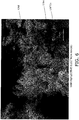
- FIG. 6 is a SEM reflective electron image of an air electrode cross section of Example 4.
- the SEM is a JSM-6610LV manufactured by JEOL Ltd., and has an acceleration voltage of 20kV.
- the plurality of CNT generally encloses the plurality of LDH to thereby function as a binder.
- the plurality of CNT 12a is in mutual contact to thereby form a long distance electron conducting path.
- the plurality of CNT is entangled as a result of entangling into the plurality of LDH.
- the plurality of LDH is respectively in a plate configuration. A portion of the surface of the LDH particles is exposed.
- the average particle diameter of the plurality of LNFCu particles is preferably smaller than the average particle diameter of the LDH particles.
- the LNFCu particles are supported on the LDH. Since the LNFCu particles are in mutual contact, a short distance electron conducting path is formed. The direct mutual contact of the LNFCu particles and CNT enables the connection of the long distance electron conducting path of CNT with the short distance electron conducting path of the plurality of the LNFCu particles.
- FIG. 4 is a schematic view illustrating a method of measuring an over-voltage of the air electrode.
- a control electrode of Pt wire is inserted into an electrolyte solution
- a Zn plate as a counter electrode opposite the air electrode is disposed to sandwich the electrolyte solution and configure the working electrode as the air electrode.
- a current having a current density of 100 mA/cm 2 is caused to flow from an open circuit configuration, and the charging voltage of the counter electrode relative to the reference electrode after 10 minutes is recorded.
- the open circuit voltage of the counter electrode relative to the reference electrode after 10 minutes is measured after returning to an open circuit state.
- the difference between the respective charging voltages and the open circuit voltage are calculated as the over-voltage (V).
- the calculation results are shown in Table 1.
- Table 1 an over-voltage of less than 1.0(V) is denoted as A (superior), an over-voltage of less than 1.5(V) is denoted as B (good), an over-voltage of greater than or equal to 1.5 (V) and less than 2.0(V) is denoted as C (acceptable), and an over-voltage of greater than or equal to 2.0(V) is denoted as D (unacceptable).
- Electron Conductive Material (volume%) Hydroxide Ion Conductive Material (volume)%) Organic Binder (volume%) Evaluation of Overvoltage of Cathode Example 1 CNT (40 volume%) Mg0.75Al0.25-LDH (60 volume%) none C C Example 2 CNT(5 volume%) Mg0.75Al0.25-LDH (95 volume%) none B B Example 3 CNT(0. 1 volume%) Mg0.75Al0.25-LDH (99.
- Example 4 it is possible to reduce the over-voltage during charging in comparison to Comparative Example 2. This result demonstrates that the effectiveness of introducing a perovskite oxide (LNFCu) as a perovskite oxide.
- LNFCu perovskite oxide
- the present invention is useful in the field of metal-air batteries since it is possible to enhance the characteristics of the air electrode.
Abstract
Description
- The present invention relates to an air electrode, a metal-air battery, an air electrode material, and a method of manufacturing an air electrode material.
- An air electrode for a metal-air battery typically comprises an electron conductive material as a principal component, and includes a layered double hydroxide and an adhesive as a secondary component (for example, reference is made to Patent Literature 1). A carbon material or the like is used as the electron conductive material. The adhesive includes use of various types of organic binders such as polyvinylidene fluoride, polytetrafluoroethylene, and a styrene/butadiene rubber, or the like.
- [Patent Literature 1] Japanese Patent Application Laid-Open No.
2012-43567 - There is a need for further enhancement of the air electrode characteristics (hydroxide ion conductivity, electron conductivity and catalyst reactivity). The present inventors have gained the new insight that further enhancement to the characteristics of the air electrode is possible by use of carbon nanotubes as a binder.
- The present invention is proposed in light of the above insight, and has the object of providing an air electrode, a metal-air battery and an air electrode material that exhibit enhanced characteristics.
- The air electrode of the present invention is an air electrode that is used in a metal-air battery, and includes a plurality of carbon nanotubes (CNT) and a plurality of layered double hydroxide particles (LDH). The plurality of layered double hydroxide particles are supported on the plurality of carbon nanotubes.
- The present invention provides an air electrode, a metal-air battery and an air electrode material that exhibit enhanced characteristics.
-
-
FIG. 1 is a cross sectional view that schematically illustrates a configuration of a zinc-airsecondary battery 10. -
FIG. 2 is an enlarged cross sectional view of an air electrode. -
FIG. 3 is a partially enlarged view ofFIG. 2 . -
FIG. 4 is a schematic view illustrating a method of measuring an air electrode resistance. -
FIG. 5 is a SEM secondary electron image of an air electrode cross section. -
FIG. 6 is a SEM reflective electron image of an air electrode cross section. - A metal-air battery according to the embodiments will be described below making reference to the figures. A metal-air battery is a concept that includes configurations such as a zinc-air secondary battery or a lithium-air secondary battery or the like. The present embodiment describes a zinc-air secondary battery as an example of a metal-air battery.
- Those aspects of configuration in the following description of the figures that are the same or similar are denoted by the same or similar reference numerals. However, the figures are merely illustrative, and the actual ratios or the like of the respective dimensions may differ.
-
FIG. 1 is a cross sectional view that schematically illustrates a configuration of a zinc-airsecondary battery 10. The zinc-airsecondary battery 10 includes anair electrode 12, an hydroxide ionconductive separator 14, anegative electrode 16 immersed in an electrolyte solution, a positive electrodecurrent collecting body 18, and ahousing 20. - The
air electrode 12 functions as a positive electrode that causes reactions that produce and/or reduce O2. Theair electrode 12 is disposed on the hydroxide ionconductive separator 14. Theair electrode 12 includes a firstprincipal surface 12S and a secondprincipal surface 12T. Theair electrode 12 comes into contact with the hydroxide ionconductive separator 14 on the firstprincipal surface 12S. Theair electrode 12 comes into contact with the positive electrodecurrent collecting body 18 on the secondprincipal surface 12T. - Although there is no particular limitation on the thickness of the
air electrode 12, it may be 1 to 100 µm, preferably may be 1 to 75 µm, more preferably may be 1 to 50 µm, and still more preferably may be 1 to 30 µm. In this manner, the surface area of the three phase interface of the gaseous phase, the electron conductive phase and the hydroxide ion conductive phase can be ensured to thereby maintain the catalytic reactivity of theair electrode 12. - The
air electrode 12 includes carbon nanotubes (abbreviated below to "CNT") and layered double hydroxide particles (abbreviated below to "LDH"). - CNT is configured from a fibrous carbon material forming a hexagonal lattice structure of graphene into a cylindrical shape. CNT may be configured as a single-walled carbon nanotube or as a multi-walled carbon nanotube. Both ends of the CNT may be closed or open.
- CNT functions as an inorganic binder. CNT maintains the shape of the
air electrode 12 by binding the LDH. CNT functions as an oxygen reducing/producing catalyst. The catalytic reactivity of theair electrode 12 can be enhanced by including CNT in theair electrode 12. CNT functions as an electron conductive body. The electron conductivity of theair electrode 12 can be enhanced by including CNT in theair electrode 12. - CNT preferably is configured inside the
air electrode 12 in an untangled state rather than in a bundled configuration. In this manner, LDH can be bound efficiently. However, a portion of CNT may be present in a bundled configuration within theair electrode 12. - LDH exhibits hydroxide ion conductivity. LDH is expressed by the general formula M2+ 1-xM3+ x (OH) 2An- x/n · mH2O (wherein M2+ is one or more types of bivalent positive ion, M3+ is one or more types of trivalent positive ion, An- is an n valent negative ion, n is an integer of at least 1, x is 0.1 to 0.4, and m is greater than or equal to 0). M2+ may include Ni2+, Mg2+, Ca2+, M n 2+, Fe2+, Co2+, Cu2+, Zn 2+. M3+ may include Fe3+, Al3+, Co3+, Cr3+, In3+. An- may include NO3-, CO3 2-, SO4 2-, OH-, Cl-, I-, Br-, F-. In particular, an Mg-Al configuration of LDH is preferred in which M2+ is Mg2+, and M3+ may includes Al3+.
- The CNT content amount in the
air electrode 12 is greater than or equal to 0.1 volume % to less than or equal to 40 volume %. In this manner, CNT that functions as an oxygen reducing/producing catalyst and an electron conductive body can be caused to function as an inorganic binder. Therefore theair electrode 12 does not require the inclusion of an organic binder to contribute in some manner to the characteristics (electron conductivity or catalytic reactivity), and therefore the characteristics of theair electrode 12 can be conspicuously enhanced when compared to a configuration in which LDH is bound by use of an organic binder. The content amount of CNT in theair electrode 12 is preferably greater than or equal to 0.1 volume % to less than or equal to 30 volume %, and more preferably greater than or equal to 0.1 volume % to less than or equal to 20 volume %. - The content amount of LDH in the
air electrode 12 may be configured as greater than or equal to 60 volume % to less than or equal to 99.9 volume %. The content amount of LDH in theair electrode 12 is preferably greater than or equal to 60 volume % to less than or equal to 90 volume %, and still more preferably the content amount of LDH in theair electrode 12 may be configured as greater than or equal to 60 volume % to less than or equal to 70 volume %. - The volume ratio of CNT to LDH in the air electrode 12 (CNT volume ÷ LDH volume) is preferably at least 0.001. In this manner, LDH can be generally enclosed in CNT and it is possible to further enhance the electron conductivity of the
air electrode 12. The volume ratio of CNT to LDH in theair electrode 12 is preferably less than or equal to 1. In this manner, it is possible to further enhance the hydroxide ion conductivity of theair electrode 12. - The
air electrode 12 may include a perovskite oxide that is expressed by the general formula ABO3-δ (wherein δ ≦ 0.4). This type of perovskite oxide preferably exhibits electron conductivity, but is not required to exhibit electron conductivity. The perovskite oxide preferably functions as an oxygen reducing/producing catalyst. - The perovskite oxide is preferably a perovskite oxide that is expressed by the general formula ABO3-δ (wherein δ ≦ 0.4), that includes at least La at the A site and that includes at least Ni, Fe and Cu at the B site. This type of perovskite oxide is expressed by the composition formula LaNi1-x-y CuxFCyO3-δ (x > 0, y> 0, x+y< 1,0 ≦ δ ≦ 0. 4). In the following description, a perovskite oxide that is expressed by the composition formula LaNi1-x-yCuxFeyO3-δ will be abbreviated as LNFCu.
- In the composition formula for LNFCu, it is preferred that x ≦ 0.5, further preferred that 0.0 1 ≦x≦ 0.5, and still more preferred that 0.05 ≦x≦ 0.3. It is possible to enhance the electron conductivity, the coefficient of thermal expansion and the catalytic reactivity of the
air electrode 12 by adjusting x and y to the above range. - LNFCu is preferably configured by a single perovskite phase. In this manner, it is possible to further enhance the electron conductivity and the catalytic reactivity of the
air electrode 12 - The perovskite oxide may contain LNFCu as a principal component. In the present embodiment, the term such that composition P "contains as a principal component" substance Q means that substance Q occupies greater than or equal to 70 wt%, and preferably occupies greater than or equal to 90 wt% of the total of composition P.
- The content amount of the perovskite oxide in the
air electrode 12 may be configured as greater than or equal to 0.1 volume % to less than or equal to 50 volume %. The content amount of the perovskite oxide in theair electrode 12 is preferably greater than or equal to 0.1 volume % to less than or equal to 40 volume %. The volume ratio of CNT relative to the perovskite oxide in the air electrode 12 (CNT volume ÷ perovskite oxide volume) may be configured as greater than or equal to 0.002 to less than or equal to 400, and is preferably greater than or equal to 0.02 to less than or equal to 40. - The
air electrode 12 may contain a minute quantity of an organic binder. The content amount of the organic binder in the air electrode is preferably less than or equal to 10 volume %. Although a thermoplastic resin or thermos-curing resin may be used as the organic binder, there is no particular limitation in this regard. - The binder is not particularly well limited and a thermoplastic resin or a thermosetting resin, preferred examples include carboxymethyl cellulose (CMC), polyethylene, polypropylene, polytetrafluoroethylene (PTFE), polyvinylidene fluoride (PVDF), styrene-butadiene rubber, tetrafluoroethylene-hexafluoroethylene copolymer, tetrafluoroethylene-hexafluoropropylene copolymer (FEP), tetrafluoroethylene-perfluoroalkyl vinyl ether copolymer (PFA), vinylidene fluoride-hexafluoropropylene copolymer, vinylidene fluoride-chlorotrifluoroethylene copolymer, an ethylene-tetrafluoroethylene copolymer (ETFE resin), polychlorotrifluoroethylene (PCTFE), vinylidene fluoride-pentafluoro propylene copolymer, a propylene-tetrafluoroethylene copolymer polymer, ethylene-chlorotrifluoroethylene copolymer (ECTFE), vinylidene fluoride-hexafluoropropylene-tetrafluoroethylene copolymer, vinylidene fluoride-perfluoromethylvinylether-tetrafluoroethylene copolymer, ethylene - acrylic acid copolymer, and any arbitrary mixture of the above.
- The hydroxide ion
conductive separator 14 is disposed between theair electrode 12 and thenegative electrode 16. The hydroxide ionconductive separator 14 makes contact with the firstprincipal surface 12S of theair electrode 12. The hydroxide ionconductive separator 14 is configured from a material that exhibits selective permeability to the hydroxide ions that are produced and consumed in theair electrode 12. - The hydroxide ion
conductive separator 14 preferably does not allow passage of alkali metal ions in the electrolyte solution or undesirable substances (such as carbon dioxide or the like) other than oxygen that is contained in the air. Such materials include compact ceramics that are inorganic solid electrolytes that exhibit hydroxide ion conductivity. - An inorganic solid electrolyte that exhibits hydroxide ion conductivity is preferably LDH that has been compacted by use of a solidifying method (for example, a hydrothermal solidifying method) that that is expressed by the general formula M2+ 1-x M3+ x(OH)2An- x/n·mH2O. An inorganic solid electrolyte that exhibits hydroxide ion conductivity may include use of a configuration that has at least one type of basic composition selected from the group consisting of NaCo2O4, LaFe3Sr3O10, Bi4Sr14 Fe24O56, NaLaTiO4, RbLaNb2O7, KLaNb2O7, and Sr4CO1.6Ti1.4O8(OH)2·x H2O.
- The above inorganic solid electrolytes have been disclosed in
PCT Laid Open Application 2011/108526 as a solid electrolyte that exhibits hydroxide ion conductivity for used in relation to a fuel cell. It is possible to suppress deterioration of the electrolyte solution resulting from production of carbon ions as a result of use of a solid electrolyte that exhibits hydroxide ion conductivity as the hydroxide ionconductive separator 14, and to suppress production of short circuiting between the positive and negative electrodes through the hydroxide ionconductive separator 14 as a result of zinc dendrites produced during charging. - The hydroxide ion
conductive separator 14 may be configured as a composite body including a particle group containing the inorganic solid electrolyte that exhibits hydroxide ion conductivity and a component that assists in the curing or compaction of the particle group. - The hydroxide ion
conductive separator 14 may be also configured as a composite body including an open-pore porous body that is used as a substrate and an inorganic solid electrolyte that is deposited or grown in the pores to thereby embed the pores of the porous body. The porous body may be configured as an insulating material such as a porous sheet or the like that is configured from a resin foam or a fibrous material, or a ceramic such as alumina, zirconia, or the like. - The relative density of the hydroxide ion
conductive separator 14 as calculated by use of an Archimedes method is preferably greater than or equal to 88%, more preferably greater than or equal to 90%, and still more preferably greater than or equal to 94%. - There is no particular limitation on the shape of the hydroxide ion
conductive separator 14, and a dense plate shape or film configuration is possible. When formed as a plate, the thickness of the hydroxide ionconductive separator 14 may be configured as 0.001 to 0.05 mm, preferably 0.001 to 0.01 mm, and more preferably 0.001 to 0.005 mm. - A higher hydroxide ion conductivity in the hydroxide ion
conductive separator 14 is preferred, and typically exhibits a conductivity of 1×10⁻⁴~1×10⁻¹S/m(1 ×10-3~1 mS/cm), and more typically 1×10⁻⁴~1×10⁻²S/m(1×10-3 ~1×10⁻¹mS/cm). - The
negative electrode 16 is disposed on the opposite side of theair electrode 12 to thereby sandwich the hydroxide ionconductive separator 14. Thenegative electrode 16 is immersed in an electrolyte solution. - The
negative electrode 16 includes zinc or a zinc alloy that functions as a negative electrode active material. There is no particular limitation in relation to the shape of thenegative electrode 16, and a configuration as a particle, plate or gel is possible with a particle or gel configuration being preferably in light of reaction rate. The particle diameter of a particle-shapednegative electrode 16 is preferably 30 to 350 µm. A gel-shapednegative electrode 16 is preferably shaped into a gel configuration by mixing and agitating a non-mercury zinc alloy powder having a particle diameter of 100 to 300 µm, an alkali electrolyte solution and a thickener (gelling agent). - The zinc alloy includes mercury alloys or non-mercury alloys with magnesium, aluminum, lithium, bismuth, indium, lead, or the like. The zinc alloy is suitably a non-mercury zinc alloy without addition of mercury or lead. It is preferred to include aluminum, bismuth, indium or a combination thereof. The zinc alloy more preferably contains 50 to 1000 ppm bismuth, 100 to 1000 ppm indium, and 10 to 100 ppm aluminum and/or calcium, and still more preferably 100 to 500 ppm bismuth, 300 to 700 ppm indium, and 20 to 50 ppm aluminum and/or calcium.
- The
negative electrode 16 may be supported on the negative electrode current collecting body. The negative electrode current collecting body includes a configuration in stainless steel, a metal plate of copper and nickel or the like, a metal mesh, carbon paper, an oxide conductor, or the like. - The electrolyte solution includes use of a known electrolyte solution that is generally used in zinc-air batteries. The electrolyte solution includes use of an alkali metal hydroxide aqueous solution such as a potassium hydroxide aqueous solution, a sodium hydroxide aqueous solution, or the like, an aqueous solution including zinc chloride or zinc perchlorate, a non-aqueous solvent including zinc perchlorate, a non-aqueous solvent including a zinc bis(trifluoromethylsulfonyl) imide. The electrolyte solution is preferably a potassium hydroxide aqueous solution that is one type of an alkali metal hydroxide aqueous solution, and more preferably includes 3 to 50 wt% of potassium hydroxide (for example, 30 to 45 wt%).
- The positive electrode current collecting
body 18 is disposed on the opposite side of the hydroxide ionconductive separator 14 to thereby sandwich theair electrode 12. The positive electrode current collectingbody 18 makes contact with the secondprincipal surface 12T of theair electrode 12. - The positive electrode current collecting
body 18 preferably is configured with air permeability to enable supply of air to theair electrode 12. The positive electrode current collectingbody 18 includes a configuration in stainless steel, a metal plate of copper and nickel or the like, a metal mesh, carbon paper, an oxide conductor, or the like. - The
battery housing 20 contains theair electrode 12, the hydroxide ionconductive separator 14, thenegative electrode 16 and the positive electrode current collectingbody 18. Thebattery housing 20 includes anair electrode housing 22, annegative electrode housing 24, anair electrode gasket 26 and annegative electrode gasket 28. - The
air electrode housing 22 contains theair electrode 12, the hydroxide ionconductive separator 14, and the positive electrode current collectingbody 18.Pores 20a are formed in theair electrode housing 22 to enable passage of external air. Thenegative electrode housing 24 contains thenegative electrode 16. - The
air electrode gasket 26 is disposed along an inner peripheral edge of theair electrode housing 22. Although there is no limitation in relation to the material, shape and structure of theair electrode gasket 26 and thenegative electrode gasket 28, a configuration using a material that exhibits insulating characteristics such as nylon or the like is preferred. Air tight characteristics of the inner portion of theair electrode housing 22 and thenegative electrode housing 24 are ensured by sandwiching the hydroxide ionconductive separator 14 with theair electrode gasket 26 and thenegative electrode gasket 28. - Next, the detailed microstructure of the
air electrode 12 will be explained.FIG. 2 is an enlarged cross sectional view of an air electrode.FIG. 3 is a partially enlarged view ofFIG. 2 . - As illustrated in
FIG. 2 andFIG. 3 , theair electrode 12 is disposed between the hydroxide ionconductive separator 14 and the positive electrode current collectingbody 18. Theair electrode 12 includes a plurality ofCNT 12a and a plurality ofLDH particles 12b. - The
CNT 12a has a string shape. Although theCNT 12a in the present embodiment has a structure that is wound into a spiral, it may have a linear shape, a curved shape, or a bow shape. Although the average length of theCNT 12a is greater than or equal to 0.1 µm, there is no limitation in this regard. Although the average diameter of theCNT 12a is greater than or equal to 1.0 nm, there is no limitation in this regard. - The plurality of
CNT 12a generally encloses the plurality ofLDH 12b. The plurality ofCNT 12a preferably is entangled into the plurality ofLDH 12b. In this manner, the shape of theair electrode 12 can be strongly maintained. It is preferred that at least a portion of theCNT 12a in the plurality ofCNT 12a makes mutual contact. In this manner, a long distance electron conducting path can be formed. It is preferred that at least a portion of theCNT 12a in the plurality ofCNT 12a is connected in a vertical direction (referred to below as "the thickness direction") to the firstprincipal surface 12S or the secondprincipal surface 12T. In this manner, the electron conductivity of theair electrode 12 in the thickness direction can be enhanced. - The particle shape of the
LDH particles 12b is tabular. Although theLDH particles 12b in the present embodiment are formed as an elliptic plate, they may be formed as a disc or square plate. The average particle diameter of theLDH particles 12b is preferably less than or equal to 10 µm. The average particle diameter of theLDH particles 12b may be greater than or equal to 0.01 µm and less than or equal to 5 µm. The average particle diameter of theLDH particles 12b is preferably less than or equal to 1 µm. The average particle diameter of theLDH particles 12b is the diameter of a tabular particle when observing the particle shape using an SEM (scanning electron microscope). - The
LDH particles 12b are supported by the string-shapedCNT 12a. TheLDH particles 12b may be supported indirectly by theCNT 12a through anotherLDH particle 12b, but are preferably supported by making direct contact with theCNT 12a. TheLDH particles 12b may make direct contact with a plurality ofCNT 12a. It is possible to promote the catalytic activity of theair electrode 12 by causing a reaction between the hydroxide ions that pass through theLDH particles 12b and the electrons that pass through theCNT 12a. There is no particular limitation in relation to the ratio of particles ofLDH particles 12b that make direct contact with theCNT 12a of the plurality ofLDH particles 12b, but a value of greater than or equal to 90% is preferred. - At least a portion of the
LDH particles 12b of the plurality ofLDH particles 12b is preferably in mutual contact. In this manner, a conducting path for hydroxide ions can be formed. In particular, it is preferred that the plurality ofLDH particles 12b is connected in the thickness direction. - As illustrated in
FIG. 2 andFIG. 3 , theair electrode 12 preferably contains a plurality ofperovskite oxide particles 12c. Theperovskite oxide particles 12c are preferably LNFCu particles. - The particle shape of the
perovskite oxide particles 12c in the present embodiment is ball shaped, but may also be spherical, complex or irregular. The average particle diameter of theperovskite oxide particles 12c may be greater than or equal to 0.01 µm and less than or equal to 10 µm. The average particle diameter of theperovskite oxide particles 12c is preferably smaller than the average particle diameter of theLDH particles 12b. More specifically, the average particle diameter of theperovskite oxide particles 12c is preferably less than or equal to 0.1 µm. The average particle diameter of theperovskite oxide particles 12c is the particle diameter when observing the particle shape using an SEM. - The
perovskite oxide particles 12c are preferably supported on theLDH particles 12b. Theperovskite oxide particles 12c may be disposed on the two principal surfaces of thetabular LDH particles 12b, or may be disposed on a side surface of thetabular LDH particles 12b. Theperovskite oxide particles 12c preferably do not completely cover the entire surface of theLDH particles 12b. In this manner, a connection betweenLDH particles 12b and a connection between theCNT 12a and theLDH particles 12b can be created since a portion of the surface of theLDH particles 12b can be exposed. - At least a portion of the
perovskite oxide particles 12c of the plurality ofperovskite oxide particles 12c is preferably in mutual contact. In this manner, a short distance electron conducting path can be formed. At least a portion of theperovskite oxide particles 12c of the plurality ofperovskite oxide particles 12c preferably makes direct contact with theCNT 12a. In this manner, the long distance electron conducting path of theCNT 12a can be connected with the short distance electron conducting path of the plurality ofperovskite oxide particles 12c. - Firstly, a CNT dispersion is prepared. The CNT dispersion can be prepared by dispersing CNT in a solvent (for example, water or the like). The CNT concentration in the CNT dispersion can be configured as 0.1 wt% to 2.0 wt%, but there is no particular limitation in this regard. CNT is difficult to disperse in a liquid that exhibits a property of tending to coagulate. Consequently, a commercially available CNT dispersion (for example, a (Tradename) SWNT dispersion manufactured by Meijo Carbon (Ltd.)) may be used.
- Next, the CNT dispersion is heated to vaporize the solvent and thereby concentrate the CNT dispersion. In this manner, the viscosity of the CNT dispersion can be configured to greater than or equal to 0.1 Pa.s and less than or equal to 200 Pa.s and thereby more effectively realize the function of the CNT dispersion as a binder.
- Next, an LDH powder expressed by the general formula above of M2+ 1-xM3 + x(OH)2An-x/n·mH2O is prepared.
- Then, a perovskite oxide powder is prepared in the event that a perovskite oxide is to be introduced into the
air electrode 12. In the following description, a perovskite oxide powder will be described that uses an LNFCu powder. Firstly, a lanthanum hydroxide powder, a nickel oxide powder, a copper oxide powder and an iron oxide powder are dried (110 degrees C, 12 hours). Then, the respective powders that have been dried so that La, Ni, Cu and Fe coincide with desired molar ratios are weighed. Then, after wet blending of the weighed powders in an aqueous medium and drying, a blended powder is prepared by passing through a sieve. Next, a calcined powder is prepared by placing the blended powder in a covered alumina crucible and calcining in an oxygen atmosphere (900 to 1200 degrees C, 12 hours). Next, after pulverizing the calcined powder and applying uniaxial pressing, a green body is formed by use of a CIP (cold isostatic press). Then, a sintered body is prepared by disposing the green body in an alumina sheath and firing in an oxygen atmosphere (900 to 1200 degrees C, 12 hours). Then the sintered body is subjected to wet grinding using a ball mill to prepare an LNFCu powder. - Next, the concentrated CNT dispersion and the LDH powder are respectively weighed. At that time, the perovskite oxide powder is also weighed in the event of preparing a perovskite oxide powder.
- Then, after placing the weighed CNT dispersion and the LDH powder into an agate mortar, the agate mortar is heated using a hot stirrer (60 to 90 degrees C) to thereby blend the CNT dispersion and the LDH powder and prepare a blended paste (example of air electrode material).
- At that time, the solvent is vaporized from the blended paste until reaching a viscosity that enables printing in the following step. The volume ratio (CNT volume ÷ LDH volume) of CNT in the blended paste to LDH is greater than or equal to 0.001 to less than or equal to 1. In this manner, the preparation of a blended paste using a CNT dispersion enables a conspicuous improvement in the uniformity of the blending characteristics of CNT in the blended paste in comparison to a configuration in which CNT is used in a powdered or sheet shape. As a result, the
air electrode 12 can be given an overall uniform configuration. When weighing the perovskite oxide powder, the perovskite oxide powder can be blended together with the CNT dispersion and the LDH powder. - Then, after using a printing method to print the blended paste onto the positive electrode current collecting body 18 (for example, carbon paper or the like), drying is performed (60 to 120 degrees C, 1 to 12 hours) in an atmosphere of air. A layered body of the
air electrode 12 and the positive electrode current collectingbody 18 is completed in accordance with the above description. - The following description will describe the preparation of an LDH separator as an example of the hydroxide ion
conductive separator 14. - Next, an LDH powder expressed by the general formula of M2+ 1-xM3+ x (OH)2An- x/n·mH2O is prepared.
- Next, an LDH green body having a relative density of 43 to 65% is prepared by pressure molding (for example, CIP or the like) of an LDH powder. The relative density of the LDH green body is a value that is calculated by dividing the density calculated on the basis of the weight and the dimensions of the LDH green body by a theoretical density. To suppress an effect of adsorbed moisture on the relative density, the LDH green body is preferably prepared by use of LDH powder that is stored for at least 24 hours in a desiccator at less than or equal to a relative humidity of 20%.
- Next, an LDH fired body is prepared by firing the LDH green body (400 to 850 degrees C, 1 to 10 hours). The weight of the LDH fired body is preferably 57 to 65% of the LDH green body, and the volume of the LDH fired body is preferably less than or equal to 70 to 76% of the LDH green body.
- Next, the LDH fired body is retained in or directly above an aqueous solution that includes negative ions (An-) of n valency to produce an LDH body by hydrothermal synthesis (20 to 200 degrees C, 1 to 50 hours).
- Then, excess moisture is removed from the LDH body in an environment of a temperature of less than or equal to 300 degrees C and less than or equal to 25% humidity to thereby complete an LDH separator.
- Then, the
negative electrode gasket 28 is mounted on thenegative electrode housing 24 that contains thenegative electrode 16 that is immersed in the electrolyte solution. - Next, the hydroxide ion
conductive separator 14, the layered body of theair electrode 12 and the positive electrode current collectingbody 18, and theair electrode gasket 26 are disposed in sequence on thenegative electrode gasket 28, and then theair electrode housing 22 on which theair electrode gasket 26 is mounted is covered. - The zinc-air
secondary battery 10 is completed in the above manner. - Although an embodiment of the present invention has been described, the present invention is not limited to the above embodiment, and various modifications are possible within a scope that does not depart from the spirit of the invention.
- Although a zinc-air
secondary battery 10 has been described as an example of a metal-air battery, theair electrode 12 of the present invention may also be used in related to other metal-air batteries such as lithium-air secondary batteries or the like. - The zinc air
secondary battery 10 is configured to include theair electrode 12, the hydroxide ionconductive separator 14, thenegative electrode 16 that is immersed in an electrolyte solution, the positive electrode current collectingbody 18, and thehousing 20. However, a configuration of at least theair electrode 12, and thenegative electrode 16 is sufficient. - There is no particular limitation in relation to the shape of the zinc-air
secondary battery 10, and for example, it may be configured in a coin shape, button shape, sheet shape, layered shape, cylindrical shape, flat shape, square shape, or the like. - The
air electrode 12 may be adapted also in relation to a large secondary battery that is used in an electrical automobile or the like in relation to merely a small type of secondary battery. - The zinc-air
secondary battery 10 may further comprise a positive electrode that is designated for charging. A designated charging positive electrode is disclosed in Japanese Patent Application Laid-Open No.2010-176941 conductive separator 14 is low. Furthermore, since the production of oxygen at theair electrode 12 during charging operations is suppressed, it is possible to suppress deterioration or corrosion of theair electrode 12. The designated charging positive electrode includes carbon or metal titanium mesh configurations or the like. - The examples of a metal-air battery according to the present invention will be described below. However, the present invention is not thereby limited to the following examples.
- A metal-air battery according to Examples 1 to 3 is prepared as described below.
- Firstly CNT as an inorganic binder is dispersed in water to prepare a CNT dispersion having a CNT concentration of 0.1 wt%.
- Then, the CNT dispersion is heated to vaporize the solvent, and configure a viscosity of the CNT dispersion of 25 Pa.s.
- Next, a commercial available Mg0.75-Al0.25 LDH powder (Tradename: DHT6 manufactured by Kyowa Chemical Industry Co., Ltd) is prepared.
- Then, the concentrated CNT dispersion and the LDH powder are weighed so that the blending ratio of CNT and LDH coincides with the values illustrated in Table 1.
- Next, after placing the weighed CNT dispersion and the LDH powder into an agate mortar, the agate mortar is heated using a hot stirrer to thereby blend the CNT dispersion and the LDH powder and prepare a blended paste (air electrode material). During this process, visual confirmation is performed that the CNT in the blended paste is uniformly blended. Although not shown in Table 1, the mixture prepared by blending CNT powder (product name: EC-P manufactured by manufactured by Meijo Carbon (Ltd.)) did not result in a uniform blending since the CNT underwent aggregation. In the same manner, although not shown in Table 1, the mixture prepared by using finely cut CNT sheets (product name: EC-P paper manufactured by manufactured by Meijo Carbon (Ltd.)) did not result in a uniform blending due to difficulties in sufficiently cutting the sheets in a uniformly fine manner.
- Then, after printing the blended paste onto carbon paper, drying is performed at 80 degrees C in an atmosphere of air. A layered body of the air electrode and the positive electrode current collecting body is completed in accordance with the above description.
- Next, an ion example membrane (product name: Neosepta AHA manufactured by Astom Corporation) is prepared as a separator.
- Then, the negative electrode gasket is mounted onto the negative electrode housing that contains a polypropylene non-woven fabric immersed in a 1M KOH aqueous solution, and the separator, the layered body formed from the air electrode and the positive electrode current collecting body, and the air electrode gasket are disposed in sequence on the negative electrode gasket. Then the air electrode housing on which the air electrode gasket is mounted is covered.
- A metal-air battery according to Example 4 is prepared as described below.
- Firstly CNT as an inorganic binder is dispersed in water to prepare a CNT dispersion having a CNT concentration of 0.1 wt%.
- Then, the CNT dispersion is heated to vaporize the solvent, and configure a viscosity of the CNT dispersion of 25 Pa.s.
- Then, a commercial available Mg0.75-Al0.25 LDH powder (Tradename: DHT6 manufactured by Kyowa Chemical Industry Co., Ltd) is prepared.
- Then, a lanthanum hydroxide powder, a nickel oxide powder, a copper oxide powder and an iron oxide powder are dried (110 degrees C, 12 hours) and weighed so that x = 0.2 and y = 0.05 in the composition formula LaNi1-x-yCuxFeyO3-δ. Then, after wet blending the weighed powders in an aqueous medium and drying, a blended powder is prepared by passing through a sieve. Next, a calcined powder is prepared by placing the blended powder in a covered alumina crucible and calcining in an oxygen atmosphere (1100 degrees C, 12 hours). Next, after pulverizing the calcined powder and preparing a green body by applying uniaxial pressing, a sintered body is prepared by disposing the green body in an alumina sheath and firing in an oxygen atmosphere (1100 degrees C, 12 hours). Then the sintered body is subjected to wet grinding using a ball mill to prepare an LNFCu powder as an example of a perovskite oxide.
- Next, the concentrated CNT dispersion, the LDH powder and the LNFCu powder are weighed so that the blending ratio of CNT, LDH and LNFCu coincides with the values illustrated in Table 1.
- Next, after placing the weighed CNT dispersion, the LDH powder and the LNFCu powder into an agate mortar, the agate mortar is heated using a hot stirrer to thereby blend the CNT dispersion, the LDH powder and the LNFCu powder and prepare a blended paste (air electrode material). During this process, visual confirmation is performed that the CNT in the blended paste is uniformly blended.
- Then, after printing the blended paste onto carbon paper, drying is performed at 80 degrees C in an atmosphere of air. A layered body of the air electrode and the positive electrode current collecting body is completed in accordance with the above description.
- Next, an ion example membrane (product name: Neosepta AHA manufactured by Astom Corporation) is prepared as a separator.
- Then, the negative electrode gasket is mounted onto the negative electrode housing that contains a polypropylene non-woven fabric immersed in a 1M KOH aqueous solution, and the separator, the layered body formed from the air electrode and the positive electrode current collecting body, and the air electrode gasket are disposed in sequence on the negative electrode gasket. Then the air electrode housing on which the air electrode gasket is mounted is covered.
- A metal-air battery according to Example 5 is prepared as described below.
- Firstly a concentrated CNT dispersion is prepared in the same manner as Examples 1 to 3.
- Next, an LDH powder is prepared in the same manner as Examples 1 to 3.
- A dispersion is prepared using polytetrafluoroethylene as an organic binder (PTFE) (PTFE concentration 60 wt.%) (Product Name: EC-TFE-500ML manufactured by ElectroChem Inc.).
- Next, the concentrated CNT dispersion, the LNFCu powder and the PTFE dispersion are weighed so that the blending ratio of CNT, PTFE and LNFCu coincides with the values illustrated in Table 1.
- Next, after placing the weighed CNT dispersion, the PTFE dispersion and the LNFCu powder into an agate mortar, the agate mortar is heated using a hot stirrer to thereby blend the CNT dispersion, PTFE dispersion and the LNFCu powder and prepare a blended paste (air electrode material).
- Then, after printing the blended paste onto carbon paper, drying is performed at 80 degrees C in an atmosphere of air. A layered body formed from the air electrode and the positive electrode current collecting body is completed in accordance with the above description.
- Next, an ion example membrane (product name: Neosepta AHA manufactured by Astom Corporation) is prepared as a separator.
- Then, the negative electrode gasket is mounted onto the negative electrode housing that contains a polypropylene non-woven fabric immersed in a 1M KOH aqueous solution, and the separator, the layered body formed from the air electrode and the positive electrode current collecting body, and the air electrode gasket are disposed in sequence on the negative electrode gasket. Then the air electrode housing on which the air electrode gasket is mounted is covered.
- A metal-air battery according to Comparative Example 1 is prepared as described below.
- Firstly carbon black (product name: Denka Black (Powder) manufactured by Denka Company Limited) is prepared.
- Next, an LDH powder is prepared in the same manner as Examples 1 to 3.
- Then, a dispersion using PTFE as an organic binder is prepared.
- Next, the carbon black, the LNFCu powder and the PTFE powder are weighed so that the blending ratio of carbon black, PTFE and LNFCu coincides with the values illustrated in Table 1.
- Next, after placing the weighed carbon black, the PTFE dispersion and the LNFCu powder into an agate mortar, the agate mortar is heated using a hot stirrer to thereby blend the carbon black, PTFE dispersion and the LNFCu powder and prepare a blended paste (air electrode material).
- Then, after printing the blended paste onto carbon paper, drying is performed at 80 degrees C in an atmosphere of air. A layered body of the air electrode and the positive electrode current collecting body is completed in accordance with the above description.
- Next, an ion example membrane (product name: Neosepta AHA manufactured by Astom Corporation) is prepared as a separator.
- Then, the negative electrode gasket is mounted onto the negative electrode housing that contains a polypropylene non-woven fabric immersed in a 1M KOH aqueous solution, and the separator, the layered body formed from the air electrode and the positive electrode current collecting body, and the air electrode gasket are disposed in sequence on the negative electrode gasket. Then the air electrode housing on which the air electrode gasket is mounted is covered.
- A cross section of the air electrode according to Examples 1 to 5 is observed using an SEM to thereby observe the microstructure of the air electrode.
FIG. 5 is a SEM secondary electron image of an air electrode cross section of Example 4.FIG. 6 is a SEM reflective electron image of an air electrode cross section of Example 4. The SEM is a JSM-6610LV manufactured by JEOL Ltd., and has an acceleration voltage of 20kV. - As illustrated in
FIG. 5 , it is possible to observe a configuration in which the plurality of CNT generally encloses the plurality of LDH to thereby function as a binder. The plurality ofCNT 12a is in mutual contact to thereby form a long distance electron conducting path. The plurality of CNT is entangled as a result of entangling into the plurality of LDH. The plurality of LDH is respectively in a plate configuration. A portion of the surface of the LDH particles is exposed. - As illustrated in
FIG. 6 , the average particle diameter of the plurality of LNFCu particles is preferably smaller than the average particle diameter of the LDH particles. The LNFCu particles are supported on the LDH. Since the LNFCu particles are in mutual contact, a short distance electron conducting path is formed. The direct mutual contact of the LNFCu particles and CNT enables the connection of the long distance electron conducting path of CNT with the short distance electron conducting path of the plurality of the LNFCu particles. -
FIG. 4 is a schematic view illustrating a method of measuring an over-voltage of the air electrode. - Firstly, a control electrode of Pt wire is inserted into an electrolyte solution, a Zn plate as a counter electrode opposite the air electrode is disposed to sandwich the electrolyte solution and configure the working electrode as the air electrode.
- Then, a current having a current density of 100 mA/cm2 is caused to flow from an open circuit configuration, and the charging voltage of the counter electrode relative to the reference electrode after 10 minutes is recorded.
- The open circuit voltage of the counter electrode relative to the reference electrode after 10 minutes is measured after returning to an open circuit state.
- The difference between the respective charging voltages and the open circuit voltage are calculated as the over-voltage (V). The calculation results are shown in Table 1. In Table 1, an over-voltage of less than 1.0(V) is denoted as A (superior), an over-voltage of less than 1.5(V) is denoted as B (good), an over-voltage of greater than or equal to 1.5 (V) and less than 2.0(V) is denoted as C (acceptable), and an over-voltage of greater than or equal to 2.0(V) is denoted as D (unacceptable).
Table 1 Sample No. Electron Conductive Material (volume%) Hydroxide Ion Conductive Material (volume)%) Organic Binder (volume%) Evaluation of Overvoltage of Cathode Example 1 CNT (40 volume%) Mg0.75Al0.25-LDH (60 volume%) none C C Example 2 CNT(5 volume%) Mg0.75Al0.25-LDH (95 volume%) none B B Example 3 CNT(0. 1 volume%) Mg0.75Al0.25-LDH (99. 9 volume%) none C C Example 4 CNT(5 volume%) + LNFCu (1 volume%) Mg0.75A10.25-LDH (94 volume%) none A A Example 5 CNT(5 volume)%) Mg0.75A10.25-LDH (93 volume%) PTFE (2 volume)%) C C Comparative Example 1 Carbon Black (80 volume)%) Mg0.75Al0.25-LDH (10 volume%) PTFE (10 volume%) D D - As shown in Table 1, in Examples 1 to 5, it is possible to reduce the over-voltage during charging in comparison to Comparative Example 1. This is due to the enhancement in the characteristics of the air electrode (hydroxide ion conductivity, electron conductivity and catalyst reactivity) as a result of use of CNT that is an inorganic binder in substitution for an organic binder.
- As illustrated in Table 1, in Examples 2 and 4, it is possible to reduce the over-voltage during charging in comparison to Comparative Examples 1 and 3. This result demonstrates that the content amount of CNT in the air electrode is preferably less than or equal to 5 vol%.
- As illustrated in Table 1, in Example 4, it is possible to reduce the over-voltage during charging in comparison to Comparative Example 2. This result demonstrates that the effectiveness of introducing a perovskite oxide (LNFCu) as a perovskite oxide.
- The present invention is useful in the field of metal-air batteries since it is possible to enhance the characteristics of the air electrode.
-
- 10
- ZINC-AIR SECONDARY BATTERY
- 12
- AIR ELECTRODE
- 14
- HYDROXIDE ION CONDUCTIVE SEPARATOR
- 16
- NEGATIVE ELECTRODE
- 18
- POSITIVE ELECTRODE CURRENT COLLECTING BODY
- 20
- HOUSING
Claims (15)
- An air electrode used in a metal-air battery, the air electrode comprising;
a plurality of carbon nanotubes, and
a plurality of layered double hydroxide particles, wherein
the plurality of layered double hydroxide particles is supported on the plurality of carbon nanotubes. - The air electrode according to claim 1, wherein
at least a portion of the plurality of carbon nanotubes is in mutual contact. - The air electrode according to claim 1 or 2, wherein
the plurality of carbon nanotubes is entangled with the plurality of layered double hydroxide particles. - The air electrode according to claim 1 or 2, wherein
an average length of the plurality of carbon nanotubes is greater than or equal to 0.1 µm. - The air electrode according to any one of claims 1 to 4, wherein
at least a portion of the plurality of layered double hydroxide particles is in mutual contact. - The air electrode according to any one of claims 1 to 5, wherein
the respective plurality of layered double hydroxide particles is tabular in shape. - The air electrode according to any one of claims 1 to 6, wherein
an average particle diameter of the plurality of layered double hydroxide particles is less than or equal to 10 µm. - The air electrode according to any one of claims 1 to 7 comprising
a plurality of perovskite oxide particles, wherein
an average particle diameter of the plurality of perovskite oxide particles is less than an average particle diameter of the plurality of layered double hydroxide particles. - The air electrode according to claim 8, wherein
the plurality of perovskite oxide particles is supported on the plurality of layered double hydroxide particles. - The air electrode according to claim 8 or 9, wherein
at least a portion of the plurality of perovskite oxide particles is in mutual contact. - The air electrode according to any one of claims 8 to 10, wherein
at least a portion of the plurality of perovskite oxide particles is in contact with the plurality of carbon nanotubes. - The air electrode according to any one of claims 8 to 11, wherein
a portion of a surface of the respective plurality of layered double hydroxide particles is exposed from the plurality of perovskite oxide particles. - A metal-air battery comprising;
the air electrode according to any one of claims 1 to 12,
a negative electrode, and
an electrolyte disposed between the air electrode and the negative electrode. - The metal-air battery according to claim 13, wherein,
the electrolyte is an inorganic solid electrolyte that exhibits hydroxide ion conductivity. - An air electrode material used in a metal-air battery, the air electrode material comprising;
a plurality of carbon nanotubes, and
a plurality of layered double hydroxide particles, wherein
the plurality of layered double hydroxide particles is in contact with the plurality of carbon nanotubes.
Applications Claiming Priority (2)
| Application Number | Priority Date | Filing Date | Title |
|---|---|---|---|
| JP2015128648 | 2015-06-26 | ||
| PCT/JP2016/069032 WO2016208769A1 (en) | 2015-06-26 | 2016-06-27 | Air electrode, metal air battery, and air electrode material |
Publications (3)
| Publication Number | Publication Date |
|---|---|
| EP3163659A1 true EP3163659A1 (en) | 2017-05-03 |
| EP3163659A4 EP3163659A4 (en) | 2017-12-13 |
| EP3163659B1 EP3163659B1 (en) | 2019-08-28 |
Family
ID=57585593
Family Applications (1)
| Application Number | Title | Priority Date | Filing Date |
|---|---|---|---|
| EP16814537.3A Active EP3163659B1 (en) | 2015-06-26 | 2016-06-27 | Air electrode, metal air battery, and air electrode material |
Country Status (5)
| Country | Link |
|---|---|
| US (1) | US10790560B2 (en) |
| EP (1) | EP3163659B1 (en) |
| JP (1) | JP6570545B2 (en) |
| CN (1) | CN107710477A (en) |
| WO (1) | WO2016208769A1 (en) |
Cited By (1)
| Publication number | Priority date | Publication date | Assignee | Title |
|---|---|---|---|---|
| CN111604015A (en) * | 2020-06-07 | 2020-09-01 | 宁夏大学 | Preparation method of shell-core structure composite material with metal compound coated by nano carbon material |
Families Citing this family (10)
| Publication number | Priority date | Publication date | Assignee | Title |
|---|---|---|---|---|
| JP6560621B2 (en) * | 2016-01-06 | 2019-08-14 | 日本特殊陶業株式会社 | Electrochemical reaction single cell, interconnector-electrochemical reaction single cell complex, and electrochemical reaction cell stack |
| JP6550193B2 (en) * | 2017-03-09 | 2019-07-24 | 日本碍子株式会社 | Method of manufacturing separator / air electrode composite |
| CN107240703A (en) * | 2017-05-10 | 2017-10-10 | 新材料与产业技术北京研究院 | Air electrode containing graphene and/or CNT and preparation method thereof and metal-air battery |
| JP6721763B2 (en) * | 2018-06-15 | 2020-07-15 | 日本碍子株式会社 | Electrochemical cell |
| JP7162133B2 (en) * | 2019-06-05 | 2022-10-27 | 日本碍子株式会社 | Air electrode/separator assembly and metal-air secondary battery |
| CN110797463B (en) * | 2019-10-30 | 2021-08-20 | 华中科技大学 | Carbon counter electrode perovskite solar cell and preparation method thereof |
| JP7011103B2 (en) * | 2020-03-02 | 2022-02-10 | 日本碍子株式会社 | Layered double hydroxides and their manufacturing methods, as well as air electrodes and metal-air secondary batteries using the layered double hydroxides. |
| KR102503501B1 (en) * | 2020-10-20 | 2023-02-23 | 재단법인대구경북과학기술원 | Membrane-electrode assembly and fuel cell comprising the same |
| KR20230125000A (en) * | 2020-12-25 | 2023-08-28 | 다이킨 고교 가부시키가이샤 | A binder made by combining single-walled carbon nanotubes and PTFE, and a composition for manufacturing electrodes and secondary batteries using the same |
| CN116885198B (en) * | 2023-09-08 | 2023-12-08 | 浙江帕瓦新能源股份有限公司 | Precursor, preparation method, positive electrode material and sodium ion battery |
Family Cites Families (10)
| Publication number | Priority date | Publication date | Assignee | Title |
|---|---|---|---|---|
| JP4996332B2 (en) * | 2007-05-17 | 2012-08-08 | 日立電線メクテック株式会社 | Heat sink and manufacturing method thereof |
| JP5158150B2 (en) * | 2010-08-17 | 2013-03-06 | トヨタ自動車株式会社 | Air electrode for metal-air battery, and metal-air battery including the air electrode |
| JP5221626B2 (en) * | 2010-10-29 | 2013-06-26 | 国立大学法人京都大学 | Air electrode for metal-air secondary battery, membrane / air electrode assembly for metal-air secondary battery and metal-air secondary battery provided with the air electrode |
| US9362568B2 (en) * | 2011-02-18 | 2016-06-07 | The Board Of Trustees Of The Leland Stanford Junior University | Battery with hybrid electrocatalysts |
| JP2013211201A (en) * | 2012-03-30 | 2013-10-10 | Tokyo Institute Of Technology | Catalyst-electrolyte composite and production method thereof |
| US20140332731A1 (en) * | 2012-04-02 | 2014-11-13 | CNano Technology Limited | Electrode Composition for Battery |
| KR101309577B1 (en) * | 2012-04-18 | 2013-09-17 | 연세대학교 산학협력단 | Cathode for li-air cell and li-air cell including the same |
| JP2014011000A (en) * | 2012-06-29 | 2014-01-20 | Hitachi Ltd | Ion conductor and electrochemical device using the same |
| US10573927B2 (en) | 2013-02-01 | 2020-02-25 | Nippon Shokubai Co., Ltd. | Electrode precursor, electrode, and cell |
| JP6532186B2 (en) * | 2013-05-23 | 2019-06-19 | 株式会社日本触媒 | Electrode precursor, electrode, and secondary battery |
-
2016
- 2016-06-27 JP JP2016568454A patent/JP6570545B2/en active Active
- 2016-06-27 CN CN201680002119.XA patent/CN107710477A/en active Pending
- 2016-06-27 WO PCT/JP2016/069032 patent/WO2016208769A1/en active Application Filing
- 2016-06-27 EP EP16814537.3A patent/EP3163659B1/en active Active
-
2017
- 2017-01-27 US US15/417,683 patent/US10790560B2/en active Active
Cited By (2)
| Publication number | Priority date | Publication date | Assignee | Title |
|---|---|---|---|---|
| CN111604015A (en) * | 2020-06-07 | 2020-09-01 | 宁夏大学 | Preparation method of shell-core structure composite material with metal compound coated by nano carbon material |
| CN111604015B (en) * | 2020-06-07 | 2022-02-22 | 宁夏大学 | Preparation method of shell-core structure composite material with metal compound coated by nano carbon material |
Also Published As
| Publication number | Publication date |
|---|---|
| EP3163659B1 (en) | 2019-08-28 |
| JP6570545B2 (en) | 2019-09-04 |
| JPWO2016208769A1 (en) | 2018-04-12 |
| EP3163659A4 (en) | 2017-12-13 |
| WO2016208769A1 (en) | 2016-12-29 |
| US10790560B2 (en) | 2020-09-29 |
| US20170141445A1 (en) | 2017-05-18 |
| CN107710477A (en) | 2018-02-16 |
Similar Documents
| Publication | Publication Date | Title |
|---|---|---|
| US10790560B2 (en) | Air electrode, metal-air battery and air electrode material | |
| JP6517606B2 (en) | Air electrode, metal-air battery, air electrode material, and method of manufacturing air electrode material | |
| Xue et al. | Transition metal oxide-based oxygen reduction reaction electrocatalysts for energy conversion systems with aqueous electrolytes | |
| JP6441900B2 (en) | Air electrode for metal-air battery | |
| CN107408743B (en) | Air electrode, water electrolysis anode, metal-air battery and water electrolysis device | |
| CN106471669B (en) | Air electrode with separator for metal-air battery | |
| JP6063283B2 (en) | All-solid battery and method for producing all-solid battery | |
| EP3316368B1 (en) | Air electrode material, air electrode and metal air battery | |
| JP6619164B2 (en) | Manufacturing method of air electrode material | |
| CN116686117A (en) | Method for producing sheet for solid-state secondary battery, and binder for solid-state secondary battery | |
| WO2014041800A1 (en) | METAL Na CELL | |
| US20130089660A1 (en) | Method for manufacturing a composite powder that can be used to constitute electrode materials | |
| JPH07215764A (en) | Electrical conductive ceramic sintered compact and its production | |
| JP2024007401A (en) | Manufacturing method of sheet for solid secondary battery, binding agent for solid secondary battery electrode, composition for electrode fabrication, electrode mixture and electrode | |
| Masri | The Study of Agar Binder and Super P Additive in Porous Zinc Anode for Zinc-air Batteries | |
| JPH07196367A (en) | Electrically conductive sintered ceramic and production thereof |
Legal Events
| Date | Code | Title | Description |
|---|---|---|---|
| STAA | Information on the status of an ep patent application or granted ep patent |
Free format text: STATUS: THE INTERNATIONAL PUBLICATION HAS BEEN MADE |
|
| PUAI | Public reference made under article 153(3) epc to a published international application that has entered the european phase |
Free format text: ORIGINAL CODE: 0009012 |
|
| STAA | Information on the status of an ep patent application or granted ep patent |
Free format text: STATUS: REQUEST FOR EXAMINATION WAS MADE |
|
| 17P | Request for examination filed |
Effective date: 20170127 |
|
| AK | Designated contracting states |
Kind code of ref document: A1 Designated state(s): AL AT BE BG CH CY CZ DE DK EE ES FI FR GB GR HR HU IE IS IT LI LT LU LV MC MK MT NL NO PL PT RO RS SE SI SK SM TR |
|
| AX | Request for extension of the european patent |
Extension state: BA ME |
|
| A4 | Supplementary search report drawn up and despatched |
Effective date: 20171110 |
|
| RIC1 | Information provided on ipc code assigned before grant |
Ipc: H01M 12/06 20060101ALI20171103BHEP Ipc: H01M 12/08 20060101ALI20171103BHEP Ipc: H01M 4/86 20060101AFI20171103BHEP Ipc: H01M 4/96 20060101ALI20171103BHEP |
|
| STAA | Information on the status of an ep patent application or granted ep patent |
Free format text: STATUS: EXAMINATION IS IN PROGRESS |
|
| 17Q | First examination report despatched |
Effective date: 20180718 |
|
| DAV | Request for validation of the european patent (deleted) | ||
| DAX | Request for extension of the european patent (deleted) | ||
| GRAP | Despatch of communication of intention to grant a patent |
Free format text: ORIGINAL CODE: EPIDOSNIGR1 |
|
| STAA | Information on the status of an ep patent application or granted ep patent |
Free format text: STATUS: GRANT OF PATENT IS INTENDED |
|
| INTG | Intention to grant announced |
Effective date: 20190320 |
|
| GRAS | Grant fee paid |
Free format text: ORIGINAL CODE: EPIDOSNIGR3 |
|
| GRAA | (expected) grant |
Free format text: ORIGINAL CODE: 0009210 |
|
| STAA | Information on the status of an ep patent application or granted ep patent |
Free format text: STATUS: THE PATENT HAS BEEN GRANTED |
|
| AK | Designated contracting states |
Kind code of ref document: B1 Designated state(s): AL AT BE BG CH CY CZ DE DK EE ES FI FR GB GR HR HU IE IS IT LI LT LU LV MC MK MT NL NO PL PT RO RS SE SI SK SM TR |
|
| REG | Reference to a national code |
Ref country code: GB Ref legal event code: FG4D |
|
| REG | Reference to a national code |
Ref country code: CH Ref legal event code: EP |
|
| REG | Reference to a national code |
Ref country code: AT Ref legal event code: REF Ref document number: 1173530 Country of ref document: AT Kind code of ref document: T Effective date: 20190915 |
|
| REG | Reference to a national code |
Ref country code: IE Ref legal event code: FG4D |
|
| REG | Reference to a national code |
Ref country code: DE Ref legal event code: R096 Ref document number: 602016019644 Country of ref document: DE |
|
| REG | Reference to a national code |
Ref country code: NL Ref legal event code: MP Effective date: 20190828 |
|
| REG | Reference to a national code |
Ref country code: LT Ref legal event code: MG4D |
|
| PG25 | Lapsed in a contracting state [announced via postgrant information from national office to epo] |
Ref country code: FI Free format text: LAPSE BECAUSE OF FAILURE TO SUBMIT A TRANSLATION OF THE DESCRIPTION OR TO PAY THE FEE WITHIN THE PRESCRIBED TIME-LIMIT Effective date: 20190828 Ref country code: LT Free format text: LAPSE BECAUSE OF FAILURE TO SUBMIT A TRANSLATION OF THE DESCRIPTION OR TO PAY THE FEE WITHIN THE PRESCRIBED TIME-LIMIT Effective date: 20190828 Ref country code: HR Free format text: LAPSE BECAUSE OF FAILURE TO SUBMIT A TRANSLATION OF THE DESCRIPTION OR TO PAY THE FEE WITHIN THE PRESCRIBED TIME-LIMIT Effective date: 20190828 Ref country code: BG Free format text: LAPSE BECAUSE OF FAILURE TO SUBMIT A TRANSLATION OF THE DESCRIPTION OR TO PAY THE FEE WITHIN THE PRESCRIBED TIME-LIMIT Effective date: 20191128 Ref country code: NL Free format text: LAPSE BECAUSE OF FAILURE TO SUBMIT A TRANSLATION OF THE DESCRIPTION OR TO PAY THE FEE WITHIN THE PRESCRIBED TIME-LIMIT Effective date: 20190828 Ref country code: SE Free format text: LAPSE BECAUSE OF FAILURE TO SUBMIT A TRANSLATION OF THE DESCRIPTION OR TO PAY THE FEE WITHIN THE PRESCRIBED TIME-LIMIT Effective date: 20190828 Ref country code: PT Free format text: LAPSE BECAUSE OF FAILURE TO SUBMIT A TRANSLATION OF THE DESCRIPTION OR TO PAY THE FEE WITHIN THE PRESCRIBED TIME-LIMIT Effective date: 20191230 Ref country code: NO Free format text: LAPSE BECAUSE OF FAILURE TO SUBMIT A TRANSLATION OF THE DESCRIPTION OR TO PAY THE FEE WITHIN THE PRESCRIBED TIME-LIMIT Effective date: 20191128 |
|
| PG25 | Lapsed in a contracting state [announced via postgrant information from national office to epo] |
Ref country code: LV Free format text: LAPSE BECAUSE OF FAILURE TO SUBMIT A TRANSLATION OF THE DESCRIPTION OR TO PAY THE FEE WITHIN THE PRESCRIBED TIME-LIMIT Effective date: 20190828 Ref country code: ES Free format text: LAPSE BECAUSE OF FAILURE TO SUBMIT A TRANSLATION OF THE DESCRIPTION OR TO PAY THE FEE WITHIN THE PRESCRIBED TIME-LIMIT Effective date: 20190828 Ref country code: GR Free format text: LAPSE BECAUSE OF FAILURE TO SUBMIT A TRANSLATION OF THE DESCRIPTION OR TO PAY THE FEE WITHIN THE PRESCRIBED TIME-LIMIT Effective date: 20191129 Ref country code: IS Free format text: LAPSE BECAUSE OF FAILURE TO SUBMIT A TRANSLATION OF THE DESCRIPTION OR TO PAY THE FEE WITHIN THE PRESCRIBED TIME-LIMIT Effective date: 20191228 Ref country code: RS Free format text: LAPSE BECAUSE OF FAILURE TO SUBMIT A TRANSLATION OF THE DESCRIPTION OR TO PAY THE FEE WITHIN THE PRESCRIBED TIME-LIMIT Effective date: 20190828 Ref country code: AL Free format text: LAPSE BECAUSE OF FAILURE TO SUBMIT A TRANSLATION OF THE DESCRIPTION OR TO PAY THE FEE WITHIN THE PRESCRIBED TIME-LIMIT Effective date: 20190828 |
|
| REG | Reference to a national code |
Ref country code: AT Ref legal event code: MK05 Ref document number: 1173530 Country of ref document: AT Kind code of ref document: T Effective date: 20190828 |
|
| PG25 | Lapsed in a contracting state [announced via postgrant information from national office to epo] |
Ref country code: TR Free format text: LAPSE BECAUSE OF FAILURE TO SUBMIT A TRANSLATION OF THE DESCRIPTION OR TO PAY THE FEE WITHIN THE PRESCRIBED TIME-LIMIT Effective date: 20190828 |
|
| PG25 | Lapsed in a contracting state [announced via postgrant information from national office to epo] |
Ref country code: DK Free format text: LAPSE BECAUSE OF FAILURE TO SUBMIT A TRANSLATION OF THE DESCRIPTION OR TO PAY THE FEE WITHIN THE PRESCRIBED TIME-LIMIT Effective date: 20190828 Ref country code: AT Free format text: LAPSE BECAUSE OF FAILURE TO SUBMIT A TRANSLATION OF THE DESCRIPTION OR TO PAY THE FEE WITHIN THE PRESCRIBED TIME-LIMIT Effective date: 20190828 Ref country code: RO Free format text: LAPSE BECAUSE OF FAILURE TO SUBMIT A TRANSLATION OF THE DESCRIPTION OR TO PAY THE FEE WITHIN THE PRESCRIBED TIME-LIMIT Effective date: 20190828 Ref country code: IT Free format text: LAPSE BECAUSE OF FAILURE TO SUBMIT A TRANSLATION OF THE DESCRIPTION OR TO PAY THE FEE WITHIN THE PRESCRIBED TIME-LIMIT Effective date: 20190828 Ref country code: EE Free format text: LAPSE BECAUSE OF FAILURE TO SUBMIT A TRANSLATION OF THE DESCRIPTION OR TO PAY THE FEE WITHIN THE PRESCRIBED TIME-LIMIT Effective date: 20190828 Ref country code: PL Free format text: LAPSE BECAUSE OF FAILURE TO SUBMIT A TRANSLATION OF THE DESCRIPTION OR TO PAY THE FEE WITHIN THE PRESCRIBED TIME-LIMIT Effective date: 20190828 |
|
| PG25 | Lapsed in a contracting state [announced via postgrant information from national office to epo] |
Ref country code: SK Free format text: LAPSE BECAUSE OF FAILURE TO SUBMIT A TRANSLATION OF THE DESCRIPTION OR TO PAY THE FEE WITHIN THE PRESCRIBED TIME-LIMIT Effective date: 20190828 Ref country code: SM Free format text: LAPSE BECAUSE OF FAILURE TO SUBMIT A TRANSLATION OF THE DESCRIPTION OR TO PAY THE FEE WITHIN THE PRESCRIBED TIME-LIMIT Effective date: 20190828 Ref country code: IS Free format text: LAPSE BECAUSE OF FAILURE TO SUBMIT A TRANSLATION OF THE DESCRIPTION OR TO PAY THE FEE WITHIN THE PRESCRIBED TIME-LIMIT Effective date: 20200224 Ref country code: CZ Free format text: LAPSE BECAUSE OF FAILURE TO SUBMIT A TRANSLATION OF THE DESCRIPTION OR TO PAY THE FEE WITHIN THE PRESCRIBED TIME-LIMIT Effective date: 20190828 |
|
| REG | Reference to a national code |
Ref country code: DE Ref legal event code: R097 Ref document number: 602016019644 Country of ref document: DE |
|
| PLBE | No opposition filed within time limit |
Free format text: ORIGINAL CODE: 0009261 |
|
| STAA | Information on the status of an ep patent application or granted ep patent |
Free format text: STATUS: NO OPPOSITION FILED WITHIN TIME LIMIT |
|
| PG2D | Information on lapse in contracting state deleted |
Ref country code: IS |
|
| 26N | No opposition filed |
Effective date: 20200603 |
|
| PG25 | Lapsed in a contracting state [announced via postgrant information from national office to epo] |
Ref country code: SI Free format text: LAPSE BECAUSE OF FAILURE TO SUBMIT A TRANSLATION OF THE DESCRIPTION OR TO PAY THE FEE WITHIN THE PRESCRIBED TIME-LIMIT Effective date: 20190828 |
|
| PG25 | Lapsed in a contracting state [announced via postgrant information from national office to epo] |
Ref country code: MC Free format text: LAPSE BECAUSE OF FAILURE TO SUBMIT A TRANSLATION OF THE DESCRIPTION OR TO PAY THE FEE WITHIN THE PRESCRIBED TIME-LIMIT Effective date: 20190828 |
|
| REG | Reference to a national code |
Ref country code: CH Ref legal event code: PL |
|
| GBPC | Gb: european patent ceased through non-payment of renewal fee |
Effective date: 20200627 |
|
| PG25 | Lapsed in a contracting state [announced via postgrant information from national office to epo] |
Ref country code: LU Free format text: LAPSE BECAUSE OF NON-PAYMENT OF DUE FEES Effective date: 20200627 |
|
| REG | Reference to a national code |
Ref country code: BE Ref legal event code: MM Effective date: 20200630 |
|
| PG25 | Lapsed in a contracting state [announced via postgrant information from national office to epo] |
Ref country code: FR Free format text: LAPSE BECAUSE OF NON-PAYMENT OF DUE FEES Effective date: 20200630 Ref country code: IE Free format text: LAPSE BECAUSE OF NON-PAYMENT OF DUE FEES Effective date: 20200627 Ref country code: GB Free format text: LAPSE BECAUSE OF NON-PAYMENT OF DUE FEES Effective date: 20200627 Ref country code: CH Free format text: LAPSE BECAUSE OF NON-PAYMENT OF DUE FEES Effective date: 20200630 Ref country code: LI Free format text: LAPSE BECAUSE OF NON-PAYMENT OF DUE FEES Effective date: 20200630 |
|
| PG25 | Lapsed in a contracting state [announced via postgrant information from national office to epo] |
Ref country code: BE Free format text: LAPSE BECAUSE OF NON-PAYMENT OF DUE FEES Effective date: 20200630 |
|
| PG25 | Lapsed in a contracting state [announced via postgrant information from national office to epo] |
Ref country code: MT Free format text: LAPSE BECAUSE OF FAILURE TO SUBMIT A TRANSLATION OF THE DESCRIPTION OR TO PAY THE FEE WITHIN THE PRESCRIBED TIME-LIMIT Effective date: 20190828 Ref country code: CY Free format text: LAPSE BECAUSE OF FAILURE TO SUBMIT A TRANSLATION OF THE DESCRIPTION OR TO PAY THE FEE WITHIN THE PRESCRIBED TIME-LIMIT Effective date: 20190828 |
|
| PG25 | Lapsed in a contracting state [announced via postgrant information from national office to epo] |
Ref country code: MK Free format text: LAPSE BECAUSE OF FAILURE TO SUBMIT A TRANSLATION OF THE DESCRIPTION OR TO PAY THE FEE WITHIN THE PRESCRIBED TIME-LIMIT Effective date: 20190828 |
|
| PGFP | Annual fee paid to national office [announced via postgrant information from national office to epo] |
Ref country code: DE Payment date: 20230502 Year of fee payment: 8 |