EP3163354A1 - Head-up display device - Google Patents
Head-up display device Download PDFInfo
- Publication number
- EP3163354A1 EP3163354A1 EP15811443.9A EP15811443A EP3163354A1 EP 3163354 A1 EP3163354 A1 EP 3163354A1 EP 15811443 A EP15811443 A EP 15811443A EP 3163354 A1 EP3163354 A1 EP 3163354A1
- Authority
- EP
- European Patent Office
- Prior art keywords
- case
- light
- source unit
- head
- display device
- Prior art date
- Legal status (The legal status is an assumption and is not a legal conclusion. Google has not performed a legal analysis and makes no representation as to the accuracy of the status listed.)
- Granted
Links
Images


Classifications
-
- G—PHYSICS
- G02—OPTICS
- G02B—OPTICAL ELEMENTS, SYSTEMS OR APPARATUS
- G02B27/00—Optical systems or apparatus not provided for by any of the groups G02B1/00 - G02B26/00, G02B30/00
- G02B27/01—Head-up displays
- G02B27/017—Head mounted
- G02B27/0176—Head mounted characterised by mechanical features
-
- G—PHYSICS
- G02—OPTICS
- G02B—OPTICAL ELEMENTS, SYSTEMS OR APPARATUS
- G02B27/00—Optical systems or apparatus not provided for by any of the groups G02B1/00 - G02B26/00, G02B30/00
- G02B27/01—Head-up displays
- G02B27/0149—Head-up displays characterised by mechanical features
-
- B—PERFORMING OPERATIONS; TRANSPORTING
- B60—VEHICLES IN GENERAL
- B60K—ARRANGEMENT OR MOUNTING OF PROPULSION UNITS OR OF TRANSMISSIONS IN VEHICLES; ARRANGEMENT OR MOUNTING OF PLURAL DIVERSE PRIME-MOVERS IN VEHICLES; AUXILIARY DRIVES FOR VEHICLES; INSTRUMENTATION OR DASHBOARDS FOR VEHICLES; ARRANGEMENTS IN CONNECTION WITH COOLING, AIR INTAKE, GAS EXHAUST OR FUEL SUPPLY OF PROPULSION UNITS IN VEHICLES
- B60K35/00—Instruments specially adapted for vehicles; Arrangement of instruments in or on vehicles
- B60K35/20—Output arrangements, i.e. from vehicle to user, associated with vehicle functions or specially adapted therefor
- B60K35/21—Output arrangements, i.e. from vehicle to user, associated with vehicle functions or specially adapted therefor using visual output, e.g. blinking lights or matrix displays
- B60K35/23—Head-up displays [HUD]
-
- G—PHYSICS
- G02—OPTICS
- G02B—OPTICAL ELEMENTS, SYSTEMS OR APPARATUS
- G02B27/00—Optical systems or apparatus not provided for by any of the groups G02B1/00 - G02B26/00, G02B30/00
- G02B27/01—Head-up displays
-
- H—ELECTRICITY
- H04—ELECTRIC COMMUNICATION TECHNIQUE
- H04N—PICTORIAL COMMUNICATION, e.g. TELEVISION
- H04N5/00—Details of television systems
- H04N5/64—Constructional details of receivers, e.g. cabinets or dust covers
-
- H—ELECTRICITY
- H04—ELECTRIC COMMUNICATION TECHNIQUE
- H04N—PICTORIAL COMMUNICATION, e.g. TELEVISION
- H04N5/00—Details of television systems
- H04N5/74—Projection arrangements for image reproduction, e.g. using eidophor
- H04N5/7475—Constructional details of television projection apparatus
- H04N5/7491—Constructional details of television projection apparatus of head mounted projectors
-
- H—ELECTRICITY
- H04—ELECTRIC COMMUNICATION TECHNIQUE
- H04N—PICTORIAL COMMUNICATION, e.g. TELEVISION
- H04N9/00—Details of colour television systems
- H04N9/12—Picture reproducers
- H04N9/31—Projection devices for colour picture display, e.g. using electronic spatial light modulators [ESLM]
- H04N9/3129—Projection devices for colour picture display, e.g. using electronic spatial light modulators [ESLM] scanning a light beam on the display screen
-
- H—ELECTRICITY
- H04—ELECTRIC COMMUNICATION TECHNIQUE
- H04N—PICTORIAL COMMUNICATION, e.g. TELEVISION
- H04N9/00—Details of colour television systems
- H04N9/12—Picture reproducers
- H04N9/31—Projection devices for colour picture display, e.g. using electronic spatial light modulators [ESLM]
- H04N9/3141—Constructional details thereof
- H04N9/3144—Cooling systems
-
- H—ELECTRICITY
- H05—ELECTRIC TECHNIQUES NOT OTHERWISE PROVIDED FOR
- H05B—ELECTRIC HEATING; ELECTRIC LIGHT SOURCES NOT OTHERWISE PROVIDED FOR; CIRCUIT ARRANGEMENTS FOR ELECTRIC LIGHT SOURCES, IN GENERAL
- H05B3/00—Ohmic-resistance heating
- H05B3/84—Heating arrangements specially adapted for transparent or reflecting areas, e.g. for demisting or de-icing windows, mirrors or vehicle windshields
-
- B—PERFORMING OPERATIONS; TRANSPORTING
- B60—VEHICLES IN GENERAL
- B60K—ARRANGEMENT OR MOUNTING OF PROPULSION UNITS OR OF TRANSMISSIONS IN VEHICLES; ARRANGEMENT OR MOUNTING OF PLURAL DIVERSE PRIME-MOVERS IN VEHICLES; AUXILIARY DRIVES FOR VEHICLES; INSTRUMENTATION OR DASHBOARDS FOR VEHICLES; ARRANGEMENTS IN CONNECTION WITH COOLING, AIR INTAKE, GAS EXHAUST OR FUEL SUPPLY OF PROPULSION UNITS IN VEHICLES
- B60K2360/00—Indexing scheme associated with groups B60K35/00 or B60K37/00 relating to details of instruments or dashboards
- B60K2360/60—Structural details of dashboards or instruments
- B60K2360/68—Features of instruments
- B60K2360/691—Housings
-
- B—PERFORMING OPERATIONS; TRANSPORTING
- B60—VEHICLES IN GENERAL
- B60K—ARRANGEMENT OR MOUNTING OF PROPULSION UNITS OR OF TRANSMISSIONS IN VEHICLES; ARRANGEMENT OR MOUNTING OF PLURAL DIVERSE PRIME-MOVERS IN VEHICLES; AUXILIARY DRIVES FOR VEHICLES; INSTRUMENTATION OR DASHBOARDS FOR VEHICLES; ARRANGEMENTS IN CONNECTION WITH COOLING, AIR INTAKE, GAS EXHAUST OR FUEL SUPPLY OF PROPULSION UNITS IN VEHICLES
- B60K2360/00—Indexing scheme associated with groups B60K35/00 or B60K37/00 relating to details of instruments or dashboards
- B60K2360/84—Mounting of dashboard components
-
- B—PERFORMING OPERATIONS; TRANSPORTING
- B60—VEHICLES IN GENERAL
- B60K—ARRANGEMENT OR MOUNTING OF PROPULSION UNITS OR OF TRANSMISSIONS IN VEHICLES; ARRANGEMENT OR MOUNTING OF PLURAL DIVERSE PRIME-MOVERS IN VEHICLES; AUXILIARY DRIVES FOR VEHICLES; INSTRUMENTATION OR DASHBOARDS FOR VEHICLES; ARRANGEMENTS IN CONNECTION WITH COOLING, AIR INTAKE, GAS EXHAUST OR FUEL SUPPLY OF PROPULSION UNITS IN VEHICLES
- B60K2360/00—Indexing scheme associated with groups B60K35/00 or B60K37/00 relating to details of instruments or dashboards
- B60K2360/92—Manufacturing of instruments
- B60K2360/96—Manufacturing of instruments by assembling
-
- G—PHYSICS
- G09—EDUCATION; CRYPTOGRAPHY; DISPLAY; ADVERTISING; SEALS
- G09G—ARRANGEMENTS OR CIRCUITS FOR CONTROL OF INDICATING DEVICES USING STATIC MEANS TO PRESENT VARIABLE INFORMATION
- G09G2320/00—Control of display operating conditions
- G09G2320/04—Maintaining the quality of display appearance
- G09G2320/041—Temperature compensation
Definitions
- the present invention relates to a head-up display device having a favorable assembling property.
- PTL 1 discloses a configuration in which, in a head-up display device for displaying a virtual image in front of a windshield of a vehicle, a light source unit having a back surface to which a heat radiator is attached is provided on the outside of a case that houses a reflecting member for reflecting display light from the light source unit toward the windshield in order to efficiently radiate heat emitted by the light source unit.
- the invention has been made in view of the above problem, and an object thereof is to provide a head-up display device having a favorable assembling property.
- a head-up display device including a cover having a light-transmissive light exit part, a first case having a light entry part on which light is incident and a housing part housing a reflecting member for reflecting light incident through the light entry part toward the light exit part, the first case being mated to the cover, a light source unit fixed to the outside of the housing part of the first case so that light is incident on the light entry part, and a second case covering the light source unit and fixed to the first case with screws, the head-up display device being for performing display on the outside by causing the reflecting member to reflect light emitted by the light source unit and transmitting the light through the light exit part of the cover, the head-up display device includes:
- a head-up display device A includes a cover 1, a first case 2, a reflecting member 3, a light source unit 4, a second case 5, a control board 6, and a third case 7 and causes the reflecting member 3 to reflect display light L projected by the light source unit 4 to project and display the display light L on the outside of the cover 1.
- This head-up display device A is mounted on a vehicle and projects display light L onto a windshield on a driver's seat side of the vehicle to form a virtual image in front of the windshield. For example, by projecting an instrument image including a driving speed and the like of the vehicle as display light L onto the windshield, a driver can check vehicle information superimposed on a scenery outside the vehicle through the windshield at the time of driving while keeping his/her eyes forward.
- the cover 1 is a cover made of, for example, resin such as polyethylene terephthalate (PET) or polycarbonate (PC).
- the cover 1 has, for example, a light exit part 10 made of light-transmissive resin such as acrylic resin and transmits display light L reflected by the reflecting member 3, thereby projecting the display light L onto the windshield.
- the first case 2 is made up of, for example, a case member obtained by performing metal mold casting on aluminum.
- a light entry part 20 for introducing display light L projected by the light source unit 4 is provided in a housing part 21 housing the reflecting member 3, and the first case 2 is mated to the cover 1.
- the light introduced through the light entry part 20 is reflected by the reflecting member 3 housed in the housing part 21, is transmitted through the light exit part 10 of the cover 1, and is projected onto the windshield.
- a wall part 22 protruded in a direction from the inside of the housing part 21 to the outside of the housing part 21 via the light entry part 20 is provided on the outside of the housing part 21 of the first case 2.
- a backlight board 40 (described below) of the light source unit 4 is fixed to the wall part 22 with screws. Heat emitted by the backlight board 40 is transmitted to the whole first case 2 via the wall part 22 and the heat is radiated to an external environment via the first case 2, and thus the whole first case 2 functions as a heat radiator of the light source unit 4.
- a heat conductive sheet for bringing the wall part 22 and the light source unit 4 into close contact with each other to reduce a contact thermal resistance may be provided between the wall part 22 and the light source unit 4.
- the reflecting member 3 is made up of a first reflecting member 30 and a second reflecting member 31.
- the first reflecting member is made up of a plane mirror
- the second reflecting member 31 is made up of a concave mirror unit that is rotatable around a rotating shaft 31a by power of a drive unit 310.
- the light source unit 4 includes the backlight board 40, a reflecting member 41, and a liquid crystal substrate 42.
- the backlight board 40 is made up of a circuit board on which an LED (Light Emitting Diode) serving as a light source is mounted and projects display light L at a brightness based on control by the control board 6. Further, the backlight board 40 is fixed to the wall part 22 with screws so that a surface on which the LED is mounted faces the reflecting member 41 and a surface (back surface) on which the LED is not mounted faces the wall part 22.
- LED Light Emitting Diode
- the reflecting member 41 is made up of a plane mirror and reflects the display light L emitted by the backlight board 40 toward a back surface of the liquid crystal substrate 42.
- the liquid crystal substrate 42 is made up of, for example, a TFT (Thin Film Transistor) type liquid crystal panel and is placed so that a surface thereof faces the light entry part 20 of the first case 2. Further, the liquid crystal substrate 42 switches a plurality of pixels to a transmissive/non-transmissive state in accordance with control by the control board 6 and causes the pixels in the transmissive state to transmit the light from the backlight board 40, thereby projecting a predetermined image as the display light L onto the light entry part 20 of the first case 2.
- TFT Thinon Film Transistor
- the second case 5 is made of, for example, opaque resin that can be easily molded, such as polypropylene (PP) that is comparatively inexpensive and has light weight, and covers the light source unit 4 and is fixed to the first case 2 with screws.
- PP polypropylene
- the control board 6 is a circuit board on which various electronic elements and wiring for controlling drive of the drive unit 310 of the second reflecting member 31, the backlight board 40 of the light source unit 4, and the liquid crystal substrate 42 are mounted.
- the control board 6 is connected to a CAN (Controller Area Network) and forms vehicle information such as a driving speed of the vehicle acquired via the CAN as an instrument image to thereby project the instrument image as display light L onto the light source unit 4. Further, the control board 6 can adjust a position of a virtual image to a height of an eyepoint of a driver by driving the drive unit 310 and rotating the second reflecting member 31 around the rotating shaft 31a to adjust an imaging position of the virtual image in a vertical direction of the windshield.
- CAN Controller Area Network
- the third case 7 is made up of, for example, a flat box-shaped case member made of aluminum and is fixed to the first case 2 with screws to cover the control board 6 so as to prevent the control board 6 from being influenced by an electromagnetic wave from the outside or prevent an electromagnetic wave emitted by the control board 6 from influencing the outside, thereby blocking an influence of an electromagnetic wave between the control board and the external environment.
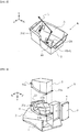
- FIG. 5 (a) is a perspective view obliquely seen from a back surface of the head-up display device A and shows screwing of the first case 2 and the second case 5 in a state in which the light source unit 4 is removed from the first case 2.
- Fig. 5(b) shows a relationship between the wall part 22 of the first case 2 and screw holes 23a, 23b, 23c, and 23d described below.
- Screw holes 51a, 51b, 51c, and 51d are provided at four corners of the second case 5, and the screw holes 23a, 23b, 23c, and 23d are provided in the first case 2 corresponding to the screw holes 51a, 51b, 51c, and 51d.
- the second case 5 is fixed to the first case 2 with screws through the corresponding screw holes.
- the screw hole 23c and the screw hole 23d of the first case 2 are positioned so that the wall part 22 is interposed therebetween, and a grooved mating part 220 is provided in a portion interposed between the screw holes 23c and the screw hole 23d of the wall part 22. Meanwhile, a protruded part to be mated to the grooved mating part 220 is provided in the second case 5. With this, when the second case 5 is fixed to the first case 2 with screws, a side between the screw hole 51c and the screw hole 51d of the second case 5 is mated to the mating part 220 of the wall part 22.
- the wall part 22 is protruded from a line segment between the screw hole 23c and the screw hole 23d in a height direction in order to increase a mating area of the mating part 220 to be mated to the second case 5.
- the screw hole 23c and the screw hole 23d of the first case 2 are provided at low positions in the height direction of the wall part 22, as compared with the screw hole 23a and the screw hole 23b.
- the side of the second case 5 made of resin to be mated to the wall part 22 is not deformed in a thickness direction of the wall part 22 because rigidity thereof is secured by the wall part 22 made of aluminum.
- the wall part 22 is protruded from the line segment between the screw hole 23c and the screw hole 23d in the height direction, the fitting area of the mating part 220 to be mated to the second case 5 is increased, and therefore the side between the screw hole 51c and the screw hole 51d of the second case 5 is provided along the wall part 22 more firmly and is prevented from being deformed in the thickness direction of the wall part 22.
- the screw hole 23c and the screw hole 23d of the first case 2 are provided at high positions in the height direction of the wall part 22, as compared with the screw hole 23a and the screw hole 23b. Therefore, when the screw hole 51a and the screw hole 51b that are not positioned are screwed first, a deforming direction caused by a screw fastening torque is matched with the thickness direction of the wall part 22, which reduces the risk that the positions of the screw hole 51c and the screw hole 51d are shifted from the positions corresponding to the screw holes of the first case 2 due to deformation caused by the screw fastening torque.
- the first case 2 and the wall part 22 are integrally formed by metal mold casting with aluminum so that the first case 2 has both a function of housing the reflecting member 3 and a function as a heat radiator in order to improve a heat radiation property.
- the first case 2 is not limited thereto, and the first case 2 may be made of resin and a metallic heat radiator having the wall part 22 may be separately formed, and the first case 2 and the metallic heat radiator may be combined with each other.
- the invention is suitable as a head-up display device mounted on a vehicle, a motorcycle, or a move provided with an agricultural machine or a construction machine.
- Reference Signs List
Landscapes
- Physics & Mathematics (AREA)
- Engineering & Computer Science (AREA)
- Optics & Photonics (AREA)
- Multimedia (AREA)
- Signal Processing (AREA)
- General Physics & Mathematics (AREA)
- Chemical & Material Sciences (AREA)
- Combustion & Propulsion (AREA)
- Transportation (AREA)
- Mechanical Engineering (AREA)
- Instrument Panels (AREA)
Abstract
Description
- The present invention relates to a head-up display device having a favorable assembling property.
- Conventionally,
PTL 1 discloses a configuration in which, in a head-up display device for displaying a virtual image in front of a windshield of a vehicle, a light source unit having a back surface to which a heat radiator is attached is provided on the outside of a case that houses a reflecting member for reflecting display light from the light source unit toward the windshield in order to efficiently radiate heat emitted by the light source unit. - PTL 1: JP-UM-A-5-23404
- In the head-up display device disclosed in
PTL 1, there is a possibility that an assembling property is further improved in fixing a second case that covers the light source unit fixed to the outside of a first case that houses the reflecting member. - The invention has been made in view of the above problem, and an object thereof is to provide a head-up display device having a favorable assembling property.
- A head-up display device according to the invention including
a cover having a light-transmissive light exit part,
a first case having a light entry part on which light is incident and a housing part housing a reflecting member for reflecting light incident through the light entry part toward the light exit part, the first case being mated to the cover,
a light source unit fixed to the outside of the housing part of the first case so that light is incident on the light entry part, and
a second case covering the light source unit and fixed to the first case with screws,
the head-up display device being for performing display on the outside by causing the reflecting member to reflect light emitted by the light source unit and transmitting the light through the light exit part of the cover,
the head-up display device includes: - a heat radiator having a higher rigidity than a rigidity of the second case and having a wall part protruded in a direction from the inside of the housing part to the outside of the housing part via the light entry part, the wall part being a part to which the light source unit is fixed with screws so that the heat radiator radiates heat of the light source unit, wherein:
- the second case and the wall part have mating parts with which the second case and the wall part are mated to each other; and
- the second case is fixed to the heat radiator or the first case with screws at positions between which the mating parts are interposed.
- According to the invention, it is possible to provide a head-up display device having a favorable assembling property.
-
- [
Fig. 1] Fig. 1 is a schematic configuration diagram of a head-up display device according to an embodiment of the invention. - [
Fig. 2] Fig. 2 is a perspective view of a surface of the head-up display device according to the same embodiment. - [
Fig. 3] Fig. 3 is a perspective view of the surface in a state in which a cover of the head-up display device according to the same embodiment is removed. - [
Fig. 4] Fig. 4 is a perspective view of a back surface of the head-up display device according to the same embodiment. - [
Fig. 5] Fig. 5 shows an assembling relationship between a first case and a second case of the head-up display device according to the same embodiment. - Hereinafter, an embodiment of the invention will be described with reference to the attached drawings.
- A head-up display device A according to the invention includes a
cover 1, afirst case 2, a reflecting member 3, alight source unit 4, asecond case 5, acontrol board 6, and athird case 7 and causes the reflecting member 3 to reflect display light L projected by thelight source unit 4 to project and display the display light L on the outside of thecover 1. - This head-up display device A is mounted on a vehicle and projects display light L onto a windshield on a driver's seat side of the vehicle to form a virtual image in front of the windshield. For example, by projecting an instrument image including a driving speed and the like of the vehicle as display light L onto the windshield, a driver can check vehicle information superimposed on a scenery outside the vehicle through the windshield at the time of driving while keeping his/her eyes forward.
- The
cover 1 is a cover made of, for example, resin such as polyethylene terephthalate (PET) or polycarbonate (PC). Thecover 1 has, for example, alight exit part 10 made of light-transmissive resin such as acrylic resin and transmits display light L reflected by the reflecting member 3, thereby projecting the display light L onto the windshield. - The
first case 2 is made up of, for example, a case member obtained by performing metal mold casting on aluminum. In thefirst case 2, alight entry part 20 for introducing display light L projected by thelight source unit 4 is provided in ahousing part 21 housing the reflecting member 3, and thefirst case 2 is mated to thecover 1. The light introduced through thelight entry part 20 is reflected by the reflecting member 3 housed in thehousing part 21, is transmitted through thelight exit part 10 of thecover 1, and is projected onto the windshield. - A
wall part 22 protruded in a direction from the inside of thehousing part 21 to the outside of thehousing part 21 via thelight entry part 20 is provided on the outside of thehousing part 21 of thefirst case 2. - A backlight board 40 (described below) of the
light source unit 4 is fixed to thewall part 22 with screws. Heat emitted by thebacklight board 40 is transmitted to the wholefirst case 2 via thewall part 22 and the heat is radiated to an external environment via thefirst case 2, and thus the wholefirst case 2 functions as a heat radiator of thelight source unit 4. - Note that a heat conductive sheet for bringing the
wall part 22 and thelight source unit 4 into close contact with each other to reduce a contact thermal resistance may be provided between thewall part 22 and thelight source unit 4. - The reflecting member 3 is made up of a first reflecting
member 30 and a second reflectingmember 31. The first reflecting member is made up of a plane mirror, and the second reflectingmember 31 is made up of a concave mirror unit that is rotatable around arotating shaft 31a by power of adrive unit 310. - The
light source unit 4 includes thebacklight board 40, a reflectingmember 41, and aliquid crystal substrate 42. - The
backlight board 40 is made up of a circuit board on which an LED (Light Emitting Diode) serving as a light source is mounted and projects display light L at a brightness based on control by thecontrol board 6. Further, thebacklight board 40 is fixed to thewall part 22 with screws so that a surface on which the LED is mounted faces the reflectingmember 41 and a surface (back surface) on which the LED is not mounted faces thewall part 22. - The reflecting
member 41 is made up of a plane mirror and reflects the display light L emitted by thebacklight board 40 toward a back surface of theliquid crystal substrate 42. - The
liquid crystal substrate 42 is made up of, for example, a TFT (Thin Film Transistor) type liquid crystal panel and is placed so that a surface thereof faces thelight entry part 20 of thefirst case 2. Further, theliquid crystal substrate 42 switches a plurality of pixels to a transmissive/non-transmissive state in accordance with control by thecontrol board 6 and causes the pixels in the transmissive state to transmit the light from thebacklight board 40, thereby projecting a predetermined image as the display light L onto thelight entry part 20 of thefirst case 2. - The
second case 5 is made of, for example, opaque resin that can be easily molded, such as polypropylene (PP) that is comparatively inexpensive and has light weight, and covers thelight source unit 4 and is fixed to thefirst case 2 with screws. - The
control board 6 is a circuit board on which various electronic elements and wiring for controlling drive of thedrive unit 310 of the second reflectingmember 31, thebacklight board 40 of thelight source unit 4, and theliquid crystal substrate 42 are mounted. - The
control board 6 is connected to a CAN (Controller Area Network) and forms vehicle information such as a driving speed of the vehicle acquired via the CAN as an instrument image to thereby project the instrument image as display light L onto thelight source unit 4. Further, thecontrol board 6 can adjust a position of a virtual image to a height of an eyepoint of a driver by driving thedrive unit 310 and rotating the second reflectingmember 31 around therotating shaft 31a to adjust an imaging position of the virtual image in a vertical direction of the windshield. - The
third case 7 is made up of, for example, a flat box-shaped case member made of aluminum and is fixed to thefirst case 2 with screws to cover thecontrol board 6 so as to prevent thecontrol board 6 from being influenced by an electromagnetic wave from the outside or prevent an electromagnetic wave emitted by thecontrol board 6 from influencing the outside, thereby blocking an influence of an electromagnetic wave between the control board and the external environment. - Screwing of the
first case 2 and thesecond case 5 will be described with reference toFig. 5. Fig. 5 (a) is a perspective view obliquely seen from a back surface of the head-up display device A and shows screwing of thefirst case 2 and thesecond case 5 in a state in which thelight source unit 4 is removed from thefirst case 2.Fig. 5(b) shows a relationship between thewall part 22 of thefirst case 2 and screwholes -
Screw holes second case 5, and thescrew holes first case 2 corresponding to thescrew holes second case 5 is fixed to thefirst case 2 with screws through the corresponding screw holes. - The
screw hole 23c and thescrew hole 23d of thefirst case 2 are positioned so that thewall part 22 is interposed therebetween, and agrooved mating part 220 is provided in a portion interposed between the screw holes 23c and thescrew hole 23d of thewall part 22. Meanwhile, a protruded part to be mated to thegrooved mating part 220 is provided in thesecond case 5. With this, when thesecond case 5 is fixed to thefirst case 2 with screws, a side between thescrew hole 51c and the screw hole 51d of thesecond case 5 is mated to themating part 220 of thewall part 22. - The
wall part 22 is protruded from a line segment between thescrew hole 23c and thescrew hole 23d in a height direction in order to increase a mating area of themating part 220 to be mated to thesecond case 5. - The
screw hole 23c and thescrew hole 23d of thefirst case 2 are provided at low positions in the height direction of thewall part 22, as compared with thescrew hole 23a and thescrew hole 23b. - With this configuration, an assembling property of the
second case 5 and thefirst case 2 is improved. - Specifically, the side of the
second case 5 made of resin to be mated to thewall part 22 is not deformed in a thickness direction of thewall part 22 because rigidity thereof is secured by thewall part 22 made of aluminum. This reduces the risk that positions of thescrew hole 51c and the screw hole 51d are shifted from positions corresponding to the screw holes of thefirst case 2 even in the case where thesecond case 5 is deformed by a screw fastening torque. Therefore, when assembling is performed by first screwing thescrew hole 51a and thescrew hole 51b that are not positioned, the risk of failure of assembly is reduced. - Further, because the
wall part 22 is protruded from the line segment between thescrew hole 23c and thescrew hole 23d in the height direction, the fitting area of themating part 220 to be mated to thesecond case 5 is increased, and therefore the side between thescrew hole 51c and the screw hole 51d of thesecond case 5 is provided along thewall part 22 more firmly and is prevented from being deformed in the thickness direction of thewall part 22. - The
screw hole 23c and thescrew hole 23d of thefirst case 2 are provided at high positions in the height direction of thewall part 22, as compared with thescrew hole 23a and thescrew hole 23b. Therefore, when thescrew hole 51a and thescrew hole 51b that are not positioned are screwed first, a deforming direction caused by a screw fastening torque is matched with the thickness direction of thewall part 22, which reduces the risk that the positions of thescrew hole 51c and the screw hole 51d are shifted from the positions corresponding to the screw holes of thefirst case 2 due to deformation caused by the screw fastening torque. - With those effects, it is possible to position the
second case 5 while the rigidity in the side between thescrew hole 51c and the screw hole 51d of thesecond case 5 mated to thewall part 22 is being secured by thewall part 22, and therefore the assembling property is not lost even in the case where the second case is made of a resin material having a comparatively low rigidity or molding precision thereof is comparatively low. Therefore, it is possible to produce the second case inexpensively while securing the assembling property. - Note that, in this embodiment, the
first case 2 and thewall part 22 are integrally formed by metal mold casting with aluminum so that thefirst case 2 has both a function of housing the reflecting member 3 and a function as a heat radiator in order to improve a heat radiation property. However, thefirst case 2 is not limited thereto, and thefirst case 2 may be made of resin and a metallic heat radiator having thewall part 22 may be separately formed, and thefirst case 2 and the metallic heat radiator may be combined with each other. - In the above description, in order to easily understand the invention, description of publicly-known unimportant technical matters has been omitted as appropriate.
- The invention is suitable as a head-up display device mounted on a vehicle, a motorcycle, or a move provided with an agricultural machine or a construction machine. Reference Signs List
-
- A:
- head-up display device
- 1:
- cover
- 10:
- light exit part
- 2:
- first case
- 20:
- light entry part
- 21:
- housing part
- 22:
- wall part
- 220:
- mating part
- 3:
- reflecting member
- 30:
- first reflecting member
- 31:
- second reflecting member
- 31a:
- rotating shaft
- 310:
- drive unit
- 4:
- light source unit
- 40:
- backlight board
- 41:
- reflecting member
- 42:
- liquid crystal substrate
- 5:
- second case
- 6:
- control board
- 7:
- third case
- L:
- display light
Claims (4)
- A head-up display device, including
a cover having a light-transmissive light exit part,
a first case having a light entry part on which light is incident and a housing part housing a reflecting member for reflecting light incident through the light entry part toward the light exit part, the first case being mated to the cover,
a light source unit fixed to the outside of the housing part of the first case so that light is incident on the light entry part, and
a second case covering the light source unit and fixed to the first case with screws,
the head-up display device being for performing display on the outside by causing the reflecting member to reflect light emitted by the light source unit and transmitting the light through the light exit part of the cover,
the head-up display device comprising:a heat radiator having a higher rigidity than a rigidity of the second case and having a wall part protruded in a direction from the inside of the housing part to the outside of the housing part via the light entry part, the wall part being a part to which the light source unit is fixed with screws so that the heat radiator radiates heat of the light source unit, wherein:the second case and the wall part have mating parts with which the second case and the wall part are mated to each other; andthe second case is fixed to the heat radiator or the first case with screws at positions between which the mating parts are interposed. - The head-up display device according to claim 1, wherein
screw fixing portions at the positions between which the mating parts are interposed and another screw fixing portion in the second case have a level difference. - The head-up display device according to claim 1 or 2, wherein
the mating parts have a recessed or protruded part. - The head-up display device according to any one of claims 1 to 3, wherein:the first case is integrally formed with the wall part by using the same material as the wall part; andthe first case also functions as a heat radiator.
Applications Claiming Priority (2)
| Application Number | Priority Date | Filing Date | Title |
|---|---|---|---|
| JP2014131129A JP6350021B2 (en) | 2014-06-26 | 2014-06-26 | Head-up display device |
| PCT/JP2015/066705 WO2015198862A1 (en) | 2014-06-26 | 2015-06-10 | Head-up display device |
Publications (3)
| Publication Number | Publication Date |
|---|---|
| EP3163354A1 true EP3163354A1 (en) | 2017-05-03 |
| EP3163354A4 EP3163354A4 (en) | 2017-11-29 |
| EP3163354B1 EP3163354B1 (en) | 2019-01-23 |
Family
ID=54937954
Family Applications (1)
| Application Number | Title | Priority Date | Filing Date |
|---|---|---|---|
| EP15811443.9A Active EP3163354B1 (en) | 2014-06-26 | 2015-06-10 | Head-up display device |
Country Status (4)
| Country | Link |
|---|---|
| US (1) | US10031341B2 (en) |
| EP (1) | EP3163354B1 (en) |
| JP (1) | JP6350021B2 (en) |
| WO (1) | WO2015198862A1 (en) |
Families Citing this family (9)
| Publication number | Priority date | Publication date | Assignee | Title |
|---|---|---|---|---|
| JP2019132868A (en) * | 2016-05-27 | 2019-08-08 | マクセル株式会社 | Head-up display device |
| CN113433702B (en) * | 2016-07-07 | 2023-04-07 | 麦克赛尔株式会社 | Vehicle with a steering wheel |
| DE102017221531B3 (en) * | 2017-11-30 | 2019-04-11 | Continental Automotive Gmbh | Head-up display system |
| JP7049580B2 (en) * | 2018-04-27 | 2022-04-07 | 日本精機株式会社 | Head-up display device |
| DE102018126476B4 (en) | 2018-10-24 | 2021-08-19 | Valeo Schalter Und Sensoren Gmbh | Head-up display and vehicle with head-up display |
| WO2021079741A1 (en) * | 2019-10-21 | 2021-04-29 | マクセル株式会社 | Light source device, and information display system and head-up display apparatus using same |
| DE102021117006A1 (en) * | 2021-07-01 | 2023-01-05 | Valeo Schalter Und Sensoren Gmbh | Heads-up display device for a motor vehicle and method for manufacturing a heads-up display device |
| CN113721366B (en) * | 2021-08-27 | 2023-08-22 | 京东方科技集团股份有限公司 | Vehicle-mounted head-up display |
| CN117999508A (en) * | 2021-09-15 | 2024-05-07 | 株式会社小糸制作所 | Image generating device and head-up display |
Family Cites Families (9)
| Publication number | Priority date | Publication date | Assignee | Title |
|---|---|---|---|---|
| JP2549734Y2 (en) | 1991-09-02 | 1997-09-30 | 矢崎総業株式会社 | Display device for vehicles |
| US6574048B2 (en) * | 2001-02-28 | 2003-06-03 | Delphi Technologies, Inc. | Method and apparatus for attenuating solar flux in a head-up display |
| JP2006065092A (en) * | 2004-08-27 | 2006-03-09 | Denso Corp | Head-up display |
| JP2008070504A (en) * | 2006-09-13 | 2008-03-27 | Nippon Seiki Co Ltd | Display |
| JP5350693B2 (en) * | 2008-07-04 | 2013-11-27 | 矢崎総業株式会社 | Vehicle display device |
| JP2012063524A (en) * | 2010-09-15 | 2012-03-29 | Nippon Seiki Co Ltd | Vehicular head-up display device |
| JP5674032B2 (en) * | 2011-03-25 | 2015-02-18 | 日本精機株式会社 | Head-up display device |
| JP2013174855A (en) * | 2012-01-24 | 2013-09-05 | Nippon Seiki Co Ltd | Head-up display device |
| JP2014085657A (en) * | 2012-10-29 | 2014-05-12 | Nippon Seiki Co Ltd | Display device |
-
2014
- 2014-06-26 JP JP2014131129A patent/JP6350021B2/en active Active
-
2015
- 2015-06-10 EP EP15811443.9A patent/EP3163354B1/en active Active
- 2015-06-10 WO PCT/JP2015/066705 patent/WO2015198862A1/en not_active Ceased
- 2015-06-10 US US15/320,374 patent/US10031341B2/en active Active
Also Published As
| Publication number | Publication date |
|---|---|
| US10031341B2 (en) | 2018-07-24 |
| EP3163354A4 (en) | 2017-11-29 |
| EP3163354B1 (en) | 2019-01-23 |
| JP2016009155A (en) | 2016-01-18 |
| WO2015198862A1 (en) | 2015-12-30 |
| JP6350021B2 (en) | 2018-07-04 |
| US20170160551A1 (en) | 2017-06-08 |
Similar Documents
| Publication | Publication Date | Title |
|---|---|---|
| EP3163354B1 (en) | Head-up display device | |
| EP3370109B1 (en) | Display device | |
| KR102015035B1 (en) | Instrument Panel for vehicle | |
| JP2009288484A (en) | Light emitting display | |
| US20160178900A1 (en) | Head-up display device | |
| JP2008070504A (en) | Display | |
| EP4163700B1 (en) | Vehicular display device | |
| JP5888003B2 (en) | Head-up display device | |
| JP2018118669A (en) | Head-up display device | |
| JP2016045388A (en) | Head-up display device | |
| JP7100818B2 (en) | Head-up display device | |
| JP2007086387A (en) | On-vehicle display device | |
| WO2020196163A1 (en) | Head-up display device | |
| JP2006011168A (en) | Head-up display device for vehicle | |
| JP2007065137A (en) | Display device for vehicle | |
| JP6287017B2 (en) | Head-up display device | |
| JP7474028B2 (en) | Head-up display | |
| JP2014142603A (en) | Display device | |
| JP2010197987A (en) | Head-up display | |
| JP2016057589A (en) | Head-up display device | |
| JP2022135389A (en) | Display device | |
| EP3678462A1 (en) | Heat dissipation structure | |
| JP7396351B2 (en) | heads up display device | |
| US20240377633A1 (en) | Image generation apparatus and head-up display | |
| JP2016057590A (en) | Head-up display device |
Legal Events
| Date | Code | Title | Description |
|---|---|---|---|
| STAA | Information on the status of an ep patent application or granted ep patent |
Free format text: STATUS: THE INTERNATIONAL PUBLICATION HAS BEEN MADE |
|
| PUAI | Public reference made under article 153(3) epc to a published international application that has entered the european phase |
Free format text: ORIGINAL CODE: 0009012 |
|
| STAA | Information on the status of an ep patent application or granted ep patent |
Free format text: STATUS: REQUEST FOR EXAMINATION WAS MADE |
|
| 17P | Request for examination filed |
Effective date: 20170112 |
|
| AK | Designated contracting states |
Kind code of ref document: A1 Designated state(s): AL AT BE BG CH CY CZ DE DK EE ES FI FR GB GR HR HU IE IS IT LI LT LU LV MC MK MT NL NO PL PT RO RS SE SI SK SM TR |
|
| AX | Request for extension of the european patent |
Extension state: BA ME |
|
| DAV | Request for validation of the european patent (deleted) | ||
| DAX | Request for extension of the european patent (deleted) | ||
| RIN1 | Information on inventor provided before grant (corrected) |
Inventor name: AZUMA, MASATOSHI |
|
| A4 | Supplementary search report drawn up and despatched |
Effective date: 20171103 |
|
| RIC1 | Information provided on ipc code assigned before grant |
Ipc: B60R 11/02 20060101ALI20171026BHEP Ipc: B60K 35/00 20060101ALI20171026BHEP Ipc: H04N 5/64 20060101ALI20171026BHEP Ipc: G02B 27/01 20060101AFI20171026BHEP |
|
| RIC1 | Information provided on ipc code assigned before grant |
Ipc: B60K 35/00 20060101ALI20180620BHEP Ipc: G02B 27/01 20060101AFI20180620BHEP Ipc: B60R 11/02 20060101ALI20180620BHEP Ipc: H04N 5/64 20060101ALI20180620BHEP |
|
| GRAP | Despatch of communication of intention to grant a patent |
Free format text: ORIGINAL CODE: EPIDOSNIGR1 |
|
| STAA | Information on the status of an ep patent application or granted ep patent |
Free format text: STATUS: GRANT OF PATENT IS INTENDED |
|
| INTG | Intention to grant announced |
Effective date: 20180727 |
|
| GRAS | Grant fee paid |
Free format text: ORIGINAL CODE: EPIDOSNIGR3 |
|
| GRAA | (expected) grant |
Free format text: ORIGINAL CODE: 0009210 |
|
| STAA | Information on the status of an ep patent application or granted ep patent |
Free format text: STATUS: THE PATENT HAS BEEN GRANTED |
|
| AK | Designated contracting states |
Kind code of ref document: B1 Designated state(s): AL AT BE BG CH CY CZ DE DK EE ES FI FR GB GR HR HU IE IS IT LI LT LU LV MC MK MT NL NO PL PT RO RS SE SI SK SM TR |
|
| REG | Reference to a national code |
Ref country code: GB Ref legal event code: FG4D |
|
| REG | Reference to a national code |
Ref country code: CH Ref legal event code: EP |
|
| REG | Reference to a national code |
Ref country code: AT Ref legal event code: REF Ref document number: 1091913 Country of ref document: AT Kind code of ref document: T Effective date: 20190215 |
|
| REG | Reference to a national code |
Ref country code: IE Ref legal event code: FG4D |
|
| REG | Reference to a national code |
Ref country code: DE Ref legal event code: R096 Ref document number: 602015023777 Country of ref document: DE |
|
| REG | Reference to a national code |
Ref country code: NL Ref legal event code: MP Effective date: 20190123 |
|
| PG25 | Lapsed in a contracting state [announced via postgrant information from national office to epo] |
Ref country code: NL Free format text: LAPSE BECAUSE OF FAILURE TO SUBMIT A TRANSLATION OF THE DESCRIPTION OR TO PAY THE FEE WITHIN THE PRESCRIBED TIME-LIMIT Effective date: 20190123 |
|
| PG25 | Lapsed in a contracting state [announced via postgrant information from national office to epo] |
Ref country code: NO Free format text: LAPSE BECAUSE OF FAILURE TO SUBMIT A TRANSLATION OF THE DESCRIPTION OR TO PAY THE FEE WITHIN THE PRESCRIBED TIME-LIMIT Effective date: 20190423 Ref country code: FI Free format text: LAPSE BECAUSE OF FAILURE TO SUBMIT A TRANSLATION OF THE DESCRIPTION OR TO PAY THE FEE WITHIN THE PRESCRIBED TIME-LIMIT Effective date: 20190123 Ref country code: SE Free format text: LAPSE BECAUSE OF FAILURE TO SUBMIT A TRANSLATION OF THE DESCRIPTION OR TO PAY THE FEE WITHIN THE PRESCRIBED TIME-LIMIT Effective date: 20190123 Ref country code: PT Free format text: LAPSE BECAUSE OF FAILURE TO SUBMIT A TRANSLATION OF THE DESCRIPTION OR TO PAY THE FEE WITHIN THE PRESCRIBED TIME-LIMIT Effective date: 20190523 Ref country code: PL Free format text: LAPSE BECAUSE OF FAILURE TO SUBMIT A TRANSLATION OF THE DESCRIPTION OR TO PAY THE FEE WITHIN THE PRESCRIBED TIME-LIMIT Effective date: 20190123 Ref country code: ES Free format text: LAPSE BECAUSE OF FAILURE TO SUBMIT A TRANSLATION OF THE DESCRIPTION OR TO PAY THE FEE WITHIN THE PRESCRIBED TIME-LIMIT Effective date: 20190123 Ref country code: LT Free format text: LAPSE BECAUSE OF FAILURE TO SUBMIT A TRANSLATION OF THE DESCRIPTION OR TO PAY THE FEE WITHIN THE PRESCRIBED TIME-LIMIT Effective date: 20190123 |
|
| REG | Reference to a national code |
Ref country code: AT Ref legal event code: MK05 Ref document number: 1091913 Country of ref document: AT Kind code of ref document: T Effective date: 20190123 |
|
| PG25 | Lapsed in a contracting state [announced via postgrant information from national office to epo] |
Ref country code: HR Free format text: LAPSE BECAUSE OF FAILURE TO SUBMIT A TRANSLATION OF THE DESCRIPTION OR TO PAY THE FEE WITHIN THE PRESCRIBED TIME-LIMIT Effective date: 20190123 Ref country code: LV Free format text: LAPSE BECAUSE OF FAILURE TO SUBMIT A TRANSLATION OF THE DESCRIPTION OR TO PAY THE FEE WITHIN THE PRESCRIBED TIME-LIMIT Effective date: 20190123 Ref country code: GR Free format text: LAPSE BECAUSE OF FAILURE TO SUBMIT A TRANSLATION OF THE DESCRIPTION OR TO PAY THE FEE WITHIN THE PRESCRIBED TIME-LIMIT Effective date: 20190424 Ref country code: IS Free format text: LAPSE BECAUSE OF FAILURE TO SUBMIT A TRANSLATION OF THE DESCRIPTION OR TO PAY THE FEE WITHIN THE PRESCRIBED TIME-LIMIT Effective date: 20190523 Ref country code: RS Free format text: LAPSE BECAUSE OF FAILURE TO SUBMIT A TRANSLATION OF THE DESCRIPTION OR TO PAY THE FEE WITHIN THE PRESCRIBED TIME-LIMIT Effective date: 20190123 Ref country code: BG Free format text: LAPSE BECAUSE OF FAILURE TO SUBMIT A TRANSLATION OF THE DESCRIPTION OR TO PAY THE FEE WITHIN THE PRESCRIBED TIME-LIMIT Effective date: 20190423 |
|
| REG | Reference to a national code |
Ref country code: DE Ref legal event code: R097 Ref document number: 602015023777 Country of ref document: DE |
|
| PG25 | Lapsed in a contracting state [announced via postgrant information from national office to epo] |
Ref country code: EE Free format text: LAPSE BECAUSE OF FAILURE TO SUBMIT A TRANSLATION OF THE DESCRIPTION OR TO PAY THE FEE WITHIN THE PRESCRIBED TIME-LIMIT Effective date: 20190123 Ref country code: DK Free format text: LAPSE BECAUSE OF FAILURE TO SUBMIT A TRANSLATION OF THE DESCRIPTION OR TO PAY THE FEE WITHIN THE PRESCRIBED TIME-LIMIT Effective date: 20190123 Ref country code: IT Free format text: LAPSE BECAUSE OF FAILURE TO SUBMIT A TRANSLATION OF THE DESCRIPTION OR TO PAY THE FEE WITHIN THE PRESCRIBED TIME-LIMIT Effective date: 20190123 Ref country code: RO Free format text: LAPSE BECAUSE OF FAILURE TO SUBMIT A TRANSLATION OF THE DESCRIPTION OR TO PAY THE FEE WITHIN THE PRESCRIBED TIME-LIMIT Effective date: 20190123 Ref country code: CZ Free format text: LAPSE BECAUSE OF FAILURE TO SUBMIT A TRANSLATION OF THE DESCRIPTION OR TO PAY THE FEE WITHIN THE PRESCRIBED TIME-LIMIT Effective date: 20190123 Ref country code: SK Free format text: LAPSE BECAUSE OF FAILURE TO SUBMIT A TRANSLATION OF THE DESCRIPTION OR TO PAY THE FEE WITHIN THE PRESCRIBED TIME-LIMIT Effective date: 20190123 Ref country code: AL Free format text: LAPSE BECAUSE OF FAILURE TO SUBMIT A TRANSLATION OF THE DESCRIPTION OR TO PAY THE FEE WITHIN THE PRESCRIBED TIME-LIMIT Effective date: 20190123 |
|
| PG25 | Lapsed in a contracting state [announced via postgrant information from national office to epo] |
Ref country code: SM Free format text: LAPSE BECAUSE OF FAILURE TO SUBMIT A TRANSLATION OF THE DESCRIPTION OR TO PAY THE FEE WITHIN THE PRESCRIBED TIME-LIMIT Effective date: 20190123 |
|
| PLBE | No opposition filed within time limit |
Free format text: ORIGINAL CODE: 0009261 |
|
| STAA | Information on the status of an ep patent application or granted ep patent |
Free format text: STATUS: NO OPPOSITION FILED WITHIN TIME LIMIT |
|
| PG25 | Lapsed in a contracting state [announced via postgrant information from national office to epo] |
Ref country code: AT Free format text: LAPSE BECAUSE OF FAILURE TO SUBMIT A TRANSLATION OF THE DESCRIPTION OR TO PAY THE FEE WITHIN THE PRESCRIBED TIME-LIMIT Effective date: 20190123 |
|
| 26N | No opposition filed |
Effective date: 20191024 |
|
| PG25 | Lapsed in a contracting state [announced via postgrant information from national office to epo] |
Ref country code: MC Free format text: LAPSE BECAUSE OF FAILURE TO SUBMIT A TRANSLATION OF THE DESCRIPTION OR TO PAY THE FEE WITHIN THE PRESCRIBED TIME-LIMIT Effective date: 20190123 |
|
| REG | Reference to a national code |
Ref country code: CH Ref legal event code: PL |
|
| GBPC | Gb: european patent ceased through non-payment of renewal fee |
Effective date: 20190610 |
|
| PG25 | Lapsed in a contracting state [announced via postgrant information from national office to epo] |
Ref country code: SI Free format text: LAPSE BECAUSE OF FAILURE TO SUBMIT A TRANSLATION OF THE DESCRIPTION OR TO PAY THE FEE WITHIN THE PRESCRIBED TIME-LIMIT Effective date: 20190123 |
|
| REG | Reference to a national code |
Ref country code: BE Ref legal event code: MM Effective date: 20190630 |
|
| PG25 | Lapsed in a contracting state [announced via postgrant information from national office to epo] |
Ref country code: TR Free format text: LAPSE BECAUSE OF FAILURE TO SUBMIT A TRANSLATION OF THE DESCRIPTION OR TO PAY THE FEE WITHIN THE PRESCRIBED TIME-LIMIT Effective date: 20190123 |
|
| PG25 | Lapsed in a contracting state [announced via postgrant information from national office to epo] |
Ref country code: IE Free format text: LAPSE BECAUSE OF NON-PAYMENT OF DUE FEES Effective date: 20190610 Ref country code: GB Free format text: LAPSE BECAUSE OF NON-PAYMENT OF DUE FEES Effective date: 20190610 |
|
| PG25 | Lapsed in a contracting state [announced via postgrant information from national office to epo] |
Ref country code: CH Free format text: LAPSE BECAUSE OF NON-PAYMENT OF DUE FEES Effective date: 20190630 Ref country code: BE Free format text: LAPSE BECAUSE OF NON-PAYMENT OF DUE FEES Effective date: 20190630 Ref country code: LI Free format text: LAPSE BECAUSE OF NON-PAYMENT OF DUE FEES Effective date: 20190630 Ref country code: LU Free format text: LAPSE BECAUSE OF NON-PAYMENT OF DUE FEES Effective date: 20190610 |
|
| PG25 | Lapsed in a contracting state [announced via postgrant information from national office to epo] |
Ref country code: FR Free format text: LAPSE BECAUSE OF NON-PAYMENT OF DUE FEES Effective date: 20190630 |
|
| PG25 | Lapsed in a contracting state [announced via postgrant information from national office to epo] |
Ref country code: CY Free format text: LAPSE BECAUSE OF FAILURE TO SUBMIT A TRANSLATION OF THE DESCRIPTION OR TO PAY THE FEE WITHIN THE PRESCRIBED TIME-LIMIT Effective date: 20190123 |
|
| PG25 | Lapsed in a contracting state [announced via postgrant information from national office to epo] |
Ref country code: MT Free format text: LAPSE BECAUSE OF FAILURE TO SUBMIT A TRANSLATION OF THE DESCRIPTION OR TO PAY THE FEE WITHIN THE PRESCRIBED TIME-LIMIT Effective date: 20190123 Ref country code: HU Free format text: LAPSE BECAUSE OF FAILURE TO SUBMIT A TRANSLATION OF THE DESCRIPTION OR TO PAY THE FEE WITHIN THE PRESCRIBED TIME-LIMIT; INVALID AB INITIO Effective date: 20150610 |
|
| PG25 | Lapsed in a contracting state [announced via postgrant information from national office to epo] |
Ref country code: MK Free format text: LAPSE BECAUSE OF FAILURE TO SUBMIT A TRANSLATION OF THE DESCRIPTION OR TO PAY THE FEE WITHIN THE PRESCRIBED TIME-LIMIT Effective date: 20190123 |
|
| PGFP | Annual fee paid to national office [announced via postgrant information from national office to epo] |
Ref country code: DE Payment date: 20250429 Year of fee payment: 11 |