EP3163225A1 - Chiller system - Google Patents
Chiller system Download PDFInfo
- Publication number
- EP3163225A1 EP3163225A1 EP15812743.1A EP15812743A EP3163225A1 EP 3163225 A1 EP3163225 A1 EP 3163225A1 EP 15812743 A EP15812743 A EP 15812743A EP 3163225 A1 EP3163225 A1 EP 3163225A1
- Authority
- EP
- European Patent Office
- Prior art keywords
- chillers
- chiller
- defrost operation
- refrigerant
- defrost
- Prior art date
- Legal status (The legal status is an assumption and is not a legal conclusion. Google has not performed a legal analysis and makes no representation as to the accuracy of the status listed.)
- Ceased
Links
Images





Classifications
-
- F—MECHANICAL ENGINEERING; LIGHTING; HEATING; WEAPONS; BLASTING
- F24—HEATING; RANGES; VENTILATING
- F24F—AIR-CONDITIONING; AIR-HUMIDIFICATION; VENTILATION; USE OF AIR CURRENTS FOR SCREENING
- F24F11/00—Control or safety arrangements
- F24F11/30—Control or safety arrangements for purposes related to the operation of the system, e.g. for safety or monitoring
- F24F11/41—Defrosting; Preventing freezing
-
- F—MECHANICAL ENGINEERING; LIGHTING; HEATING; WEAPONS; BLASTING
- F24—HEATING; RANGES; VENTILATING
- F24F—AIR-CONDITIONING; AIR-HUMIDIFICATION; VENTILATION; USE OF AIR CURRENTS FOR SCREENING
- F24F11/00—Control or safety arrangements
- F24F11/89—Arrangement or mounting of control or safety devices
-
- F—MECHANICAL ENGINEERING; LIGHTING; HEATING; WEAPONS; BLASTING
- F24—HEATING; RANGES; VENTILATING
- F24F—AIR-CONDITIONING; AIR-HUMIDIFICATION; VENTILATION; USE OF AIR CURRENTS FOR SCREENING
- F24F11/00—Control or safety arrangements
- F24F11/62—Control or safety arrangements characterised by the type of control or by internal processing, e.g. using fuzzy logic, adaptive control or estimation of values
- F24F11/63—Electronic processing
-
- F—MECHANICAL ENGINEERING; LIGHTING; HEATING; WEAPONS; BLASTING
- F25—REFRIGERATION OR COOLING; COMBINED HEATING AND REFRIGERATION SYSTEMS; HEAT PUMP SYSTEMS; MANUFACTURE OR STORAGE OF ICE; LIQUEFACTION SOLIDIFICATION OF GASES
- F25B—REFRIGERATION MACHINES, PLANTS OR SYSTEMS; COMBINED HEATING AND REFRIGERATION SYSTEMS; HEAT PUMP SYSTEMS
- F25B13/00—Compression machines, plants or systems, with reversible cycle
-
- F—MECHANICAL ENGINEERING; LIGHTING; HEATING; WEAPONS; BLASTING
- F25—REFRIGERATION OR COOLING; COMBINED HEATING AND REFRIGERATION SYSTEMS; HEAT PUMP SYSTEMS; MANUFACTURE OR STORAGE OF ICE; LIQUEFACTION SOLIDIFICATION OF GASES
- F25B—REFRIGERATION MACHINES, PLANTS OR SYSTEMS; COMBINED HEATING AND REFRIGERATION SYSTEMS; HEAT PUMP SYSTEMS
- F25B47/00—Arrangements for preventing or removing deposits or corrosion, not provided for in another subclass
- F25B47/02—Defrosting cycles
- F25B47/022—Defrosting cycles hot gas defrosting
- F25B47/025—Defrosting cycles hot gas defrosting by reversing the cycle
-
- F—MECHANICAL ENGINEERING; LIGHTING; HEATING; WEAPONS; BLASTING
- F25—REFRIGERATION OR COOLING; COMBINED HEATING AND REFRIGERATION SYSTEMS; HEAT PUMP SYSTEMS; MANUFACTURE OR STORAGE OF ICE; LIQUEFACTION SOLIDIFICATION OF GASES
- F25B—REFRIGERATION MACHINES, PLANTS OR SYSTEMS; COMBINED HEATING AND REFRIGERATION SYSTEMS; HEAT PUMP SYSTEMS
- F25B49/00—Arrangement or mounting of control or safety devices
- F25B49/02—Arrangement or mounting of control or safety devices for compression type machines, plants or systems
-
- F—MECHANICAL ENGINEERING; LIGHTING; HEATING; WEAPONS; BLASTING
- F25—REFRIGERATION OR COOLING; COMBINED HEATING AND REFRIGERATION SYSTEMS; HEAT PUMP SYSTEMS; MANUFACTURE OR STORAGE OF ICE; LIQUEFACTION SOLIDIFICATION OF GASES
- F25B—REFRIGERATION MACHINES, PLANTS OR SYSTEMS; COMBINED HEATING AND REFRIGERATION SYSTEMS; HEAT PUMP SYSTEMS
- F25B2313/00—Compression machines, plants or systems with reversible cycle not otherwise provided for
- F25B2313/003—Indoor unit with water as a heat sink or heat source
-
- F—MECHANICAL ENGINEERING; LIGHTING; HEATING; WEAPONS; BLASTING
- F25—REFRIGERATION OR COOLING; COMBINED HEATING AND REFRIGERATION SYSTEMS; HEAT PUMP SYSTEMS; MANUFACTURE OR STORAGE OF ICE; LIQUEFACTION SOLIDIFICATION OF GASES
- F25B—REFRIGERATION MACHINES, PLANTS OR SYSTEMS; COMBINED HEATING AND REFRIGERATION SYSTEMS; HEAT PUMP SYSTEMS
- F25B2313/00—Compression machines, plants or systems with reversible cycle not otherwise provided for
- F25B2313/023—Compression machines, plants or systems with reversible cycle not otherwise provided for using multiple indoor units
- F25B2313/0232—Compression machines, plants or systems with reversible cycle not otherwise provided for using multiple indoor units with bypasses
- F25B2313/02322—Compression machines, plants or systems with reversible cycle not otherwise provided for using multiple indoor units with bypasses during defrosting
-
- F—MECHANICAL ENGINEERING; LIGHTING; HEATING; WEAPONS; BLASTING
- F25—REFRIGERATION OR COOLING; COMBINED HEATING AND REFRIGERATION SYSTEMS; HEAT PUMP SYSTEMS; MANUFACTURE OR STORAGE OF ICE; LIQUEFACTION SOLIDIFICATION OF GASES
- F25B—REFRIGERATION MACHINES, PLANTS OR SYSTEMS; COMBINED HEATING AND REFRIGERATION SYSTEMS; HEAT PUMP SYSTEMS
- F25B2327/00—Compressor driving means
- F25B2327/10—Compressor driving means using engines
- F25B2327/12—Compressor driving means using engines using internal combustion engines
-
- F—MECHANICAL ENGINEERING; LIGHTING; HEATING; WEAPONS; BLASTING
- F25—REFRIGERATION OR COOLING; COMBINED HEATING AND REFRIGERATION SYSTEMS; HEAT PUMP SYSTEMS; MANUFACTURE OR STORAGE OF ICE; LIQUEFACTION SOLIDIFICATION OF GASES
- F25B—REFRIGERATION MACHINES, PLANTS OR SYSTEMS; COMBINED HEATING AND REFRIGERATION SYSTEMS; HEAT PUMP SYSTEMS
- F25B2400/00—Component parts or details not otherwise provided for in this subclass
- F25B2400/06—Several compression cycles arranged in parallel
-
- F—MECHANICAL ENGINEERING; LIGHTING; HEATING; WEAPONS; BLASTING
- F25—REFRIGERATION OR COOLING; COMBINED HEATING AND REFRIGERATION SYSTEMS; HEAT PUMP SYSTEMS; MANUFACTURE OR STORAGE OF ICE; LIQUEFACTION SOLIDIFICATION OF GASES
- F25B—REFRIGERATION MACHINES, PLANTS OR SYSTEMS; COMBINED HEATING AND REFRIGERATION SYSTEMS; HEAT PUMP SYSTEMS
- F25B27/00—Machines, plants or systems, using particular sources of energy
Definitions
- the present invention relates to a chiller system in which a plurality of heat pump chillers is connected to each other, the chillers regulating a temperature of a circulating liquid as a heat medium for temperature regulation by condensation heat or evaporation heat of a refrigerant.
- Patent Document 1 discloses a configuration in which, when the defrost operation is performed, the refrigerant is evaporated by heat absorbed from an engine coolant in an exhaust heat recovery unit by completely closing an expansion valve for an indoor heat exchanger so that no refrigerant flows into the indoor heat exchanger.
- the defrost operation is performed so as to remove frost that adheres to piping in a refrigerant-air heat exchanger.
- the temperature of the circulating liquid is not regulated during defrost operation. Therefore, if the chillers not less than a predetermined number (especially, all of the chillers) perform the defrost operation at the same time, the regulation of the temperature of the circulating liquid cannot be sufficiently (or cannot be at all) preformed.
- Patent Document 2 discloses a configuration in which: when the respective chilling units (chillers) send a request for the defrost operation, a defrost permission signal is output to the chilling units (chillers) on a predetermined number basis so that only the predetermined number of chilling units (chillers) simultaneously perform the defrost operation (see paragraph [0104] of Patent Document 2); and when the number of the chilling units (chillers) that can simultaneously perform the defrost operation is not less than two, the defrost permission signal is output in response to the defrost request signal until the number of the chilling units (chillers) reaches the number of the chilling units (chillers) that can perform the defrost operation (see paragraph [0111] of Patent Document 2). That is, Patent Document 2 discloses the configuration in which the defrost operation is permitted to the chillers in arrival order up to the number of the chillers that can simultaneously perform the defrost operation.
- Patent Document 2 discloses the configuration in which the defrost operation is permitted to the chillers in arrival order up to the number of the chillers that can simultaneously perform the defrost operation, it does not disclose the priority of the chillers on standby for the defrost operation.
- an object of the present invention is to provide a chiller system in which a plurality of heat pump chillers is connected to each other, the chiller system capable of determining the priority of the chillers on standby for a defrost operation when the defrost operation is permitted to the chillers in arrival order up to a predetermined number of chillers.
- the present invention provides a chiller system including a plurality of heat pump chillers being connected to each other, the plurality of heat pump chillers regulating a temperature of a circulating liquid as a heat medium for temperature regulation by condensation heat or evaporation heat of a refrigerant.
- Any one of the plurality of chillers is designated as a master chiller.
- Out of the plurality of chillers at least one chiller that needs a defrost operation sends a request for the defrost operation to the master chiller.
- the master chiller permits the defrost operation to the at least one chiller that has sent the request for the defrost operation in arrival order up to a predetermined number of chillers.
- At least one chiller on standby for the defrost operation sends the request for the defrost operation to the master chiller in a predetermined cycle.
- the master chiller permits a next defrost operation to one of the multiple chillers on standby in descending order of the number of the requests or a request time for the defrost operation.
- the master chiller when the chillers send the same number of the requests or have the same request time for the defrost operation, the master chiller permits the next defrost operation to one of the chillers in ascending order or in descending order of an identification number.
- the present invention also provides a chiller system including a plurality of heat pump chillers being connected to each other, the plurality of heat pump chillers regulating a temperature of a circulating liquid as a heat medium for temperature regulation by condensation heat or evaporation heat of a refrigerant, in which the chiller system further includes a control mechanism configured to control operations of the plurality of chillers. Out of the plurality of chillers, at least one chiller that needs the defrost operation sends a request for the defrost operation to the control mechanism. The control mechanism permits the defrost operation to the at least one chiller that has sent the request for the defrost operation in arrival order up to the predetermined number of chillers.
- At least one chiller on standby for the defrost operation sends the request for the defrost operation to the control mechanism in a predetermined cycle.
- the control mechanism permits the next defrost operation to one of the multiple chillers on standby in descending order of the number of the requests or the request time for the defrost operation.
- the present invention providing a chiller system in which a plurality of heat pump chillers is connected to each other, it is possible to determine the priority of the chillers on standby for the defrost operation when the defrost operation is permitted to the chillers in arrival order up to a predetermined number of the chillers.
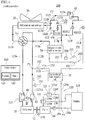
- FIG. 1 is a system diagram showing a schematic configuration of a chiller system 1 according to an embodiment of the present invention.
- a plurality of heat pump chillers 100 is connected in parallel.
- a heat pump chiller is occasionally referred to, simply, as a chiller.
- the chiller system 1 includes: the plurality of chillers 100 (1) to 100 (n) (n is an integer of ⁇ 2); and a circulating liquid circuit 200.
- Each of the chillers 100 (1) to 100 (n) has the same configuration. Accordingly, the rated output for each of the chillers 100 (1) to 100 (n) is set to the same value.
- each of the chillers 100 (1) to 100 (n) is occasionally indicated simply with the reference numeral 100.
- the chiller system 1 further includes: the circulating liquid circuit 200 that is installed in a temperature regulation target area (for example, an air conditioning target area, not shown) for circulating a circulating liquid as a heat medium for temperature regulation (for example, for air conditioning); and circulation pumps 300 (1) to 300 (n) respectively disposed corresponding to the chillers 100 (1) to 100 (n) in the circulating liquid circuit 200 so as to circulate the circulating liquid in the circulating liquid circuit 200.
- the circulation pumps 300 (1) to 300 (n) regulate the temperature of the circulating liquid that flows in the circulating liquid circuit 200.
- any circulating liquid can be used provided that it serves as the heat medium, and representative examples thereof include water.
- the circulating liquid is not limited thereto.
- water containing antifreeze liquid can be used.
- the circulating liquid circuit 200 is constituted by: an inlet main pipe 210 to flow the circulating liquid toward the plurality of chillers100 (1) to 100 (n); inlet branch pipes 211 (1) to 211 (n) to divide and flow the circulating liquid from the inlet main pipe 210 into the respective chillers 100 (1) to 100 (n); an outlet main pipe 220 to flow the circulating liquid out of the plurality of chillers 100 (1) to 100 (n); and outlet branch pipes 221 (1) to 221 (n) to flow and join the circulating liquid from the plurality of chillers 100 (1) to 100 (n) to the outlet main pipe 220.
- the inlet branch pipes 211 (1) to 211 (n) each connect a branch portion of the inlet main pipe 210 that corresponds to each chiller 100 (1) to 100 (n) and a circulating liquid flowing-in side of each chiller 100 (1) to 100 (n).
- the outlet branch pipes 221 (1) to 221 (n) each connect a circulating liquid flowing-out side of each chiller 100 (1) to 100 (n) and a confluence portion of the outlet main pipe 220 that corresponds to each chiller 100 (1) to 100 (n).
- each circulation pump 300 (1) to 300 (n) is disposed to circulate the circulating liquid in the circulating liquid circuit 200.
- the circulating liquid that is circulated by the circulation pumps 300 (1) to 300 (n) is divided and flows, from the inlet main pipe 210, into each chiller 100 (1) to 100 (n) via each inlet branch pipe 211 (1) to 211 (n), and the temperature of the circulating liquid is regulated by each chiller 100 (1) to 100 (n).
- the circulating liquid whose temperature is regulated is joined, from each chiller 100 (1) to 100 (n), to the outlet main pipe 220 via each outlet branch pipe 221 (1) to 221 (n), and is circulated in the temperature regulation target area (for example, the air conditioning target area) of the circulating liquid circuit 200.
- the respective load sides of the inlet main pipe 210 and the outlet main pipe 220 are connected to each other, for example, via a heat exchanger not shown, and constitute a closed circuit.
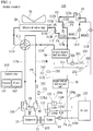
- FIG. 2 is a schematic block diagram showing one chiller 100 in the chiller system 1. Note that FIG. 2 shows one inlet branch pipe 211 out of the inlet branch pipes 211 (1) to 211 (n), one outlet branch pipe 221 out of the outlet branch pipes 221 (1) to 221 (n), and one circulation pump 300 out of the circulation pumps 300 (1) to 300 (n).
- the chiller 100 drives a compressor 10 that compresses a refrigerant so as to regulate the temperature of the circulating liquid by the condensation heat or the evaporation heat of the refrigerant.
- the chiller 100 includes: the compressor 10 that sucks and discharges the refrigerant; a refrigerant-air heat exchanger 20 that exchanges heat between the refrigerant and air (specifically, outside air); a refrigerant-air heat exchanger fan 30 for the refrigerant-air heat exchanger 20; an expansion valve 40 that expands the refrigerant compressed by the compressor 10; a refrigerant-circulating liquid heat exchanger 50 that exchanges heat between the circulating liquid and the refrigerant; an engine 60 that drives the compressor 10; and an engine exhaust heat recovery unit 70 that recovers exhaust heat of the engine 60.
- the chiller 100 is capable of executing a heating operation, a cooling operation and a defrost operation as described later.
- the expansion valve 40 is constituted by a closable first expansion valve 41 and a closable second expansion valve 42.
- the compressor 10 may be constituted by a plurality of compressors connected in parallel.
- the refrigerant-air heat exchanger 20 may be constituted by a plurality of refrigerant-air heat exchangers connected in parallel.
- the chiller 100 further includes: a refrigerant circuit 110 to circulate the refrigerant; a coolant path 120 to circulate an engine coolant for cooling the engine 60; a circulation pump 130 for the coolant path 120; and a control device 140.
- the compressor 10 In the refrigerant circuit 110, the compressor 10, the refrigerant-air heat exchanger 20, the refrigerant-circulating liquid heat exchanger 50, the expansion valve 40 and the engine exhaust heat recovery unit 70 are disposed.
- the refrigerant circuit 110 includes: a four-way valve 111; a bridge circuit 112; a high pressure gas refrigerant path 113a; a first low pressure gas refrigerant path 113b; a first gas refrigerant path 113c; a first refrigerant path 113d; a high pressure liquid refrigerant path 113e; a first low pressure gas-liquid two phase refrigerant path 113f; a second refrigerant path 113g; a second gas refrigerant path 113h; a second low pressure gas-liquid two phase refrigerant path 113i; and a second low pressure gas refrigerant path 113j.
- the four-way valve 111 is switched, in response to an instruction signal from the control device 140, between a first connection state (state shown in FIG. 2 ) in which an inlet (lower side in FIG. 2 ) is connected to one connection port (left side in FIG. 2 ) and furthermore the other connection port (right side in FIG. 2 ) is connected to an outlet (upper side in FIG. 2 ), and a second connection state in which the inlet is connected to the other connection port and furthermore the one connection port is connected to the outlet.
- a first connection state state shown in FIG. 2
- an inlet lower side in FIG. 2
- one connection port left side in FIG. 2
- furthermore the other connection port right side in FIG. 2
- the outlet upper side in FIG. 2
- the four-way valve 111 can switch the flowing direction of the refrigerant.
- the bridge circuit 112 includes four check valves (a first check valve 112a, a second check valve 112b, a third check valve 112c and a fourth check valve 112d), and is constituted by a first check valve line 1121 including two check valves (the first check valve 112a and the second check valve 112b) and a second check valve line 1122 including the remaining two check valves (the third check valve 112c and the fourth check valve 112d).
- the first check valve line 1121 is constituted by the first check valve 112a and the second check valve 112b that are connected in series so that the refrigerant flows in the same direction.
- the second check valve line 1122 is constituted by the third check valve 112c and the fourth check valve 112d that are connected in series so that the refrigerant flows in the same direction. Furthermore, the first check valve line 1121 and the second check valve line 1122 are connected in parallel so that the refrigerant flows in the same direction.
- a connection point between the first check valve 112a and the second check valve 112b is referred to as a first intermediate connection point P1
- a connection point between the first check valve 112a and the third check valve 112c is referred to as an outlet connection point P2
- a connection point between the third check valve 112c and the fourth check valve 112d is referred to as a second intermediate connection point P3
- a connection point between the second check valve 112b and the fourth check valve 112d is referred to as an inlet connection point P4.
- the high pressure gas refrigerant path 113a connects a discharge port of the compressor 10 and the inlet of the four-way valve 111.
- the first low pressure gas refrigerant path 113b connects the outlet of the four-way valve 111 and a suction port of the compressor 10.
- the first gas refrigerant path 113c connects the one connection port of the four-way valve 111 and one connection port of the refrigerant-air heat exchanger 20.
- the first refrigerant path 113d connects the other connection port of the refrigerant-air heat exchanger 20 and the first intermediate connection point P1 of the bridge circuit 112.
- the high pressure liquid refrigerant path 113e connects the outlet connection point P2 of the bridge circuit 112 and one side of the expansion valve 40 (specifically, the first expansion valve 41 and the second expansion valve 42).
- the first low pressure gas-liquid two phase refrigerant path 113f connects the other side of the first expansion valve 41 constituting the expansion valve 40 and the inlet connection point P4 of the bridge circuit 112.
- the second refrigerant path 113g connects the second intermediate connection point P3 of the bridge circuit 112 and one refrigerant connection port of the refrigerant-circulating liquid heat exchanger 50.
- the second gas refrigerant path 113h connects the other refrigerant connection port of the refrigerant-circulating liquid heat exchanger 50 and the other connection port of the four-way valve 111.
- the second low pressure gas-liquid two phase refrigerant path 113i connects the other side of the second expansion valve 42 constituting the expansion valve 40 and a refrigerant inlet of the engine exhaust heat recovery unit 70.
- the second low pressure gas refrigerant path 113j connects a refrigerant outlet of the engine exhaust heat recovery unit 70 and a confluence point P5 located in the middle of the first low pressure gas refrigerant path 113b.
- the downstream side of the confluence point P5 (the side of the compressor 10) is referred to as a confluence path 113b1.
- the respective opening degrees of the first expansion valve 41 and the second expansion valve 42 can be adjusted in response to the instruction signal from the control device 140.
- the amount of the refrigerant circulating in the refrigerant circuit 110 can be adjusted by the first expansion valve 41 and the second expansion valve 42.
- the first expansion valve 41 and the second expansion valve 42 are configured by connecting a plurality of closable expansion valves in parallel. In this way, the first expansion valve 41 and the second expansion valve 42 can adjust the amount of the refrigerant circulating in the refrigerant circuit 110 by being combined as the expansion valve(s) to be opened.
- the chiller 100 further includes an oil separator 81, an accumulator 82 and a receiver 83.
- the oil separator 81 is disposed in the high pressure gas refrigerant path 113a, and separates a lubricant oil of the compressor 10 contained in the refrigerant so as to return the separated lubricant oil to the compressor 10 via a valve 81a (more specifically, a solenoid valve).
- the accumulator 82 is disposed in the confluence path 113b1 of the first low pressure gas refrigerant path 113b, and separates the liquid refrigerant that has not been completely evaporated by the refrigerant-circulating liquid heat exchanger 50 serving as an evaporator or by the refrigerant-air heat exchanger 20 serving as an evaporator.
- the receiver 83 is disposed in the high pressure liquid refrigerant path 113e, and temporarily stores the high pressure liquid refrigerant from the bridge circuit 112.
- the coolant path 120 constitutes the path for the engine coolant that cools the engine 60, and includes a first thermostat type switching valve 121, a second thermostat type switching valve 122, a radiator 123, an outlet path 124a, an inlet path 124b, and a first path 124c to a fifth path 124g.
- the outlet path 124a connects an outlet of the engine 60 and an inlet (lower side in FIG. 2 ) of the first thermostat type switching valve 121.
- the inlet path 124b connects an outlet of the radiator 123 and an inlet of the engine 60.
- the first path 124c connects one outlet (upper side in FIG. 2 ) of the first thermostat type switching valve 121 and an inlet (left side in FIG. 2 ) of the second thermostat type switching valve 122.
- the second path 124d connects the other outlet (right side in FIG. 2 ) of the first thermostat type switching valve 121 and an inlet of the radiator 123.
- the third path 124e connects one outlet (upper side in FIG.
- the fourth path 124f connects the other outlet (right side in FIG. 2 ) of the second thermostat type switching valve 122 and a confluence point P6 located in the middle of the inlet path 124b.
- the fifth path 124g connects a coolant outlet of the engine exhaust heat recovery unit 70 and a confluence point P7 located upstream of the confluence point P6 of the inlet path 124b.
- the circulation pump 130 is disposed in the inlet path 124b, between the inlet of the engine 60 and the confluence point P6.
- the circulation pump 130 circulates the engine coolant in the coolant path 120 in response to the instruction signal from the control device 140.
- the engine exhaust heat recovery unit 70 belongs to both of the refrigerant circuit 110 and the coolant path 120.
- the first thermostat type switching valve 121 flows the engine coolant from the engine 60 toward the second thermostat type switching valve 122 when the temperature of the engine coolant is less than a predetermined first temperature (for example, 71°C).
- a predetermined first temperature for example, 71°C
- the first thermostat type switching valve 121 flows the engine coolant from the engine 60 toward the radiator 123 when the temperature of the engine coolant is not less than the first temperature.
- the coolant path 120 can circulate the engine coolant toward the second thermostat type switching valve 122 when the temperature of the engine coolant is less than the first temperature, while it can circulate the engine coolant toward the radiator 123 when the temperature of the engine coolant is not less than the first temperature.
- the second thermostat type switching valve 122 flows the engine coolant from the first thermostat type switching valve 121 toward both of the engine exhaust heat recovery unit 70 and the confluence point P6 of the inlet path 124b when the temperature of the engine coolant is less than a predetermined second temperature (for example, 60°C) that is lower than the first temperature.
- a predetermined second temperature for example, 60°C
- the second thermostat type switching valve 122 flows the engine coolant from the first thermostat type switching valve 121 toward the engine exhaust heat recovery unit 70 when the temperature of the engine coolant is not less than the second temperature.
- the coolant path 120 can circulate the engine coolant toward both of the engine exhaust heat recovery unit 70 and the confluence point P6 of the inlet path 124b when the temperature of the engine coolant is less than the second temperature, while it can circulate the engine coolant toward the engine exhaust heat recovery unit 70 when the temperature of the engine coolant is not less than the second temperature but less than the first temperature.
- the temperature of the engine coolant can be detected by a temperature sensor (not shown) disposed in the coolant path 120.
- the inlet branch pipe 211 which is a part of the circulating liquid circuit 200, connects a circulating liquid inlet of the refrigerant-circulating liquid heat exchanger 50 and a branch portion of the inlet main pipe 210 (see FIG. 1 ) corresponding to the chiller 100.
- the outlet branch pipe 221 which is a part of the circulating liquid circuit 200, connects a circulating liquid outlet of the refrigerant-circulating liquid heat exchanger 50 and a confluence portion of the outlet main pipe 220 (see FIG. 1 ) corresponding to the chiller 100.
- the refrigerant-circulating liquid heat exchanger 50 belongs to both of the refrigerant circuit 110 and the circulating liquid circuit 200.
- the compressor 10 is connected to the engine 60 via a clutch 11.
- the clutch 11 switches, in response to the instruction signal from the control device 140, between a connection state in which the drive force is transmitted from the engine 60 to the compressor 10 and a block state in which the transmission of the drive force from the engine 60 to the compressor 10 is blocked.
- the chiller 100 further includes a first pressure sensor 151, a first temperature sensor 161, a second pressure sensor 152, a second temperature sensor 162 and a rotation speed sensor 170.
- the first pressure sensor 151 and the first temperature sensor 161 are disposed in the confluence path 113b1, and detect respectively the pressure and the temperature of the refrigerant in the confluence path 113b1.
- the second pressure sensor 152 and the second temperature sensor 162 are disposed in the second low pressure gas refrigerant path 113j, and detect respectively the pressure and the temperature of the refrigerant in the second low pressure gas refrigerant path 113j.
- the rotation speed sensor 170 is disposed in the engine 60, and detects the rotational speed of the engine 60.
- the circulating liquid circuit 200 includes an influent circulating liquid temperature sensor 231 and an effluent circulating liquid temperature sensor 232.
- the influent circulating liquid temperature sensor 231 is disposed in the inlet branch pipe 211, and detects the temperature of the circulating liquid that flows into the refrigerant-circulating liquid heat exchanger 50 (more specifically, the circulating liquid in the inlet branch pipe 211).
- the effluent circulating liquid temperature sensor 232 is disposed in the outlet branch pipe 221, and detects the temperature of the circulating liquid that flows out of the refrigerant-circulating liquid heat exchanger 50 (more specifically, the circulating liquid in the outlet branch pipe 221).
- the control device 140 controls, according to detection signals from various sensors, driving of the refrigerant circuit 110, the coolant path 120 and the circulating liquid circuit 200.
- the chiller 100 can adjust the temperature of the circulating liquid that flows in the circulating liquid circuit 200.
- the control device 140 causes the compressor 10 to compress the refrigerant that is sucked from the first low pressure gas refrigerant path 113b and to discharge the compressed refrigerant to the high pressure gas refrigerant path 113a.
- the control device 140 makes the four-way valve 111 a first connection state in which the high pressure gas refrigerant path 113a is communicated with the first gas refrigerant path 113c and furthermore the second gas refrigerant path 113h is communicated with the first low pressure gas refrigerant path 113b.
- the control device 140 makes the four-way valve 111 a second connection state in which the high pressure gas refrigerant path 113a is communicated with the second gas refrigerant path 113h and furthermore the first gas refrigerant path 113c is communicated with the first low pressure gas refrigerant path 113b.
- the refrigerant-air heat exchanger 20 serves as a condenser to cause the refrigerant to release heat and liquefy during cooling operation, and serves as an evaporator to cause the refrigerant to absorb heat and vaporize during heating operation.
- the refrigerant-circulating liquid heat exchanger 50 serves as a cooler to cause the refrigerant to absorb heat and cool the circulating liquid during cooling operation, and serves as a heater to cause the refrigerant to release heat and heat the circulating liquid during heating operation.
- the engine exhaust heat recovery unit 70 serves as an evaporator to cause the refrigerant to absorb heat and vaporize.
- the first expansion valve 41 and the second expansion valve 42 are arranged, in parallel, downstream of the bridge circuit 112.
- the first expansion valve 41 adjusts the flow rate of the refrigerant that flows toward the refrigerant-circulating liquid heat exchanger 50 via the bridge circuit 112 during cooling operation, and adjusts the flow rate of the refrigerant that flows toward the refrigerant-air heat exchanger 20 via the bridge circuit 112 during heating operation.
- the second expansion valve 42 adjusts, in response to the instruction signal from the control device 140, the flow rate of the refrigerant that flows toward the engine exhaust heat recovery unit 70.
- the control device 140 includes a processor 141 constituted of a microcomputer such as a CPU (central processing unit), and a memory 142 including a non-volatile memory such as a ROM (read only memory) and a volatile memory such as a RAM (random access memory).
- a processor 141 constituted of a microcomputer such as a CPU (central processing unit)
- a memory 142 including a non-volatile memory such as a ROM (read only memory) and a volatile memory such as a RAM (random access memory).
- the processor 141 executes a control program previously stored in the ROM of the memory 142 by loading the control program on the RAM of the memory 142. Thus, operations of the respective component elements are controlled.
- FIG. 3 is a schematic block diagram showing the chiller 100 that performs the cooling operation.
- the control device 140 switches the four-way valve 111 to the first connection state in which the high pressure gas refrigerant path 113a is communicated with the first gas refrigerant path 113c and furthermore the second gas refrigerant path 113h is communicated with the first low pressure gas refrigerant path 113b.
- the refrigerant in a state of high pressure gas hereinafter referred to as the "high pressure gas refrigerant”
- the compressor 10 flows into the refrigerant-air heat exchanger 20 via the oil separator 81.
- the temperature of the high pressure gas refrigerant that flows into the refrigerant-air heat exchanger 20 is higher than the temperature of the air that passes through the refrigerant-air heat exchanger 20. For this reason, the heat is transferred from the high pressure gas refrigerant to the air. As a result, the high pressure gas refrigerant loses the condensation heat and liquefies, thus becomes the refrigerant in a state of a high pressure liquid (hereinafter referred to as the "high pressure liquid refrigerant"). That is, in the cooling operation, the refrigerant-air heat exchanger 20 serves as a condenser of the refrigerant, in which the high pressure gas refrigerant releases heat.
- the high pressure liquid refrigerant flows from the refrigerant-air heat exchanger 20 to the first intermediate connection point P1 of the bridge circuit 112 via the first refrigerant path 113d. Since the first intermediate connection point P1 is located on the outlet side of the second check valve 112b and on the inlet side of the first check valve 112a, the high pressure liquid refrigerant does not flow to the second check valve 112b and the third check valve 112c, but flows to the high pressure liquid refrigerant path 113e from the first intermediate connection point P1, via the first check valve 112a and the outlet connection point P2.
- control device 140 When the control device 140 performs the cooling operation, it opens the first expansion valve 41 and closes the second expansion valve 42, so that the high pressure liquid refrigerant flows through the first expansion valve 41 but does not flow through the second expansion valve 42. Thus, the high pressure liquid refrigerant passes through the first expansion valve 41 via the receiver 83 disposed in the high pressure liquid refrigerant path 113e.
- the high pressure liquid refrigerant When passing through the first expansion valve 41, the high pressure liquid refrigerant expands and becomes a refrigerant in a state of a low pressure gas-liquid two phase (hereinafter referred to as the "low pressure gas-liquid two phase refrigerant").
- the low pressure gas-liquid two phase refrigerant flows from the first low pressure gas-liquid two phase refrigerant path 113f to the inlet connection point P4 of the bridge circuit 112.
- the inlet connection point P4 is located on the inlet side of the second check valve 112b and the fourth check valve 112d.
- the high pressure liquid refrigerant flows through the first intermediate connection point P1 and the outlet connection point P2.
- the low pressure gas-liquid two phase refrigerant does not flow to the second check valve 112b and the third check valve 112c because of the pressure difference from the high pressure liquid refrigerant that flows through the first intermediate connection point P1 and the outlet connection point P2.
- the low pressure gas-liquid two phase refrigerant flows from the inlet connection point P4 to the refrigerant-circulating liquid heat exchanger 50 via the fourth check valve 112d, the second intermediate connection point P3 and the second refrigerant path 113g.
- the temperature of the low pressure gas-liquid two phase refrigerant that flows on the side of the refrigerant circuit 110 relative to the refrigerant-circulating liquid heat exchanger 50 is lower than the temperature of the circulating liquid that flows on the side of the circulating liquid circuit 200 relative to the refrigerant-circulating liquid heat exchanger 50. For this reason, the heat is transferred from the circulating liquid to the low pressure gas-liquid two phase refrigerant. As a result, the low pressure gas-liquid two phase refrigerant obtains the evaporation heat and vaporizes, thus becomes the refrigerant in a state of a low pressure gas (hereinafter referred to as the "low pressure gas refrigerant").
- the circulating liquid is cooled by the heat absorbing action of the refrigerant. That is, in the cooling operation, the refrigerant-circulating liquid heat exchanger 50 serves as a cooler of the circulating liquid, in which the low pressure gas-liquid two phase refrigerant absorbs heat.
- the low pressure gas refrigerant flows from the refrigerant-circulating liquid heat exchanger 50 to the second gas refrigerant path 113h.
- the control device 140 communicates the second gas refrigerant path 113h with the first low pressure gas refrigerant path 113b by the four-way valve 111.
- the low pressure gas refrigerant is sucked into the compressor 10 via the accumulator 82 disposed in the first low pressure gas refrigerant path 113b.
- FIG. 4 is a schematic block diagram showing the chiller 100 that performs the heating operation.
- the control device 140 switches the four-way valve 111 to the second connection state in which the high pressure gas refrigerant path 113a is communicated with the second gas refrigerant path 113h and furthermore the first gas refrigerant path 113c is communicated with the first low pressure gas refrigerant path 113b. In this way, the high pressure gas refrigerant that is discharged from the compressor 10 flows into the refrigerant-circulating liquid heat exchanger 50 via the oil separator 81.
- the temperature of the high pressure gas refrigerant that flows on the side of the refrigerant circuit 110 relative to the refrigerant-circulating liquid heat exchanger 50 is higher than the temperature of the circulating liquid that flows on the side of the circulating liquid circuit 200 relative to the refrigerant-circulating liquid heat exchanger 50. For this reason, the heat is transferred from the high pressure gas refrigerant to the circulating liquid. As a result, the high pressure gas refrigerant loses the condensation heat and liquefies, thus becomes the high pressure liquid refrigerant. On the other hand, the circulating liquid is heated by the heat releasing action of the refrigerant. That is, in the heating operation, the refrigerant-circulating liquid heat exchanger 50 serves as a heater of the circulating liquid, in which the high pressure gas refrigerant releases heat.
- the high pressure liquid refrigerant flows from the refrigerant-circulating liquid heat exchanger 50 to the second intermediate connection point P3 of the bridge circuit 112 via the second refrigerant path 113g. Since the second intermediate connection point P3 is located on the inlet side of the third check valve 112c and on the outlet side of the fourth check valve 112d, the high pressure liquid refrigerant does not flow to the first check valve 112a and the fourth check valve 112d, but flows to the high pressure liquid refrigerant path 113e from the second intermediate connection point P3, via the third check valve 112c and the outlet connection point P2.
- control device 140 When the control device 140 performs the heating operation, it opens the first expansion valve 41 and closes the second expansion valve 42, so that the high pressure liquid refrigerant flows through the first expansion valve 41 but does not flow through the second expansion valve 42. Thus, the high pressure liquid refrigerant passes through the first expansion valve 41 via the receiver 83 disposed in the high pressure liquid refrigerant path 113e.
- the high pressure liquid refrigerant When passing through the first expansion valve 41, the high pressure liquid refrigerant expands and becomes the low pressure gas-liquid two phase refrigerant.
- the low pressure gas-liquid two phase refrigerant flows from the first low pressure gas-liquid two phase refrigerant path 113f to the inlet connection point P4 of the bridge circuit 112.
- the inlet connection point P4 is located on the inlet side of the second check valve 112b and the fourth check valve 112d.
- the high pressure liquid refrigerant flows through the second intermediate connection point P3 and the outlet connection point P2.
- the low pressure gas-liquid two phase refrigerant does not flow to the fourth check valve 112d and the first check valve 112a because of the pressure difference from the high pressure liquid refrigerant that flows through the second intermediate connection point P3 and the outlet connection point P2.
- the low pressure gas-liquid two phase refrigerant flows from the inlet connection point P4 to the refrigerant-air heat exchanger 20 via the second check valve 112b and the first refrigerant path 113d.
- the temperature of the low pressure gas-liquid two phase refrigerant that flows through the refrigerant-air heat exchanger 20 is lower than the temperature of the air that passes through the refrigerant-air heat exchanger 20. For this reason, the heat is transferred from the air to the low pressure gas-liquid two phase refrigerant. As a result, the low pressure gas-liquid two phase refrigerant obtains the evaporation heat and vaporizes, thus becomes the low pressure gas refrigerant. That is, in the heating operation, the refrigerant-air heat exchanger 20 serves as an evaporator of the refrigerant, in which the low pressure gas-liquid two phase refrigerant absorbs heat.
- the low pressure gas refrigerant flows from the refrigerant-air heat exchanger 20 to the first gas refrigerant path 113c.
- the control device 140 communicates the first gas refrigerant path 113c with the first low pressure gas refrigerant path 113b by the four-way valve 111.
- the low pressure gas refrigerant is sucked into the compressor 10 via the accumulator 82 disposed in the first low pressure gas refrigerant path 113b.
- the low pressure gas-liquid two phase refrigerant is supplied to the refrigerant-air heat exchanger 20, thus piping in the refrigerant-air heat exchanger 20 is cooled.
- frost may adheres to the piping in the refrigerant-air heat exchanger 20 depending on conditions such as an outside air temperature. Then, the chiller 100 performs the defrost operation.
- FIG. 5 is a schematic block diagram showing the chiller 100 that performs the defrost operation.
- the control device 140 switches, as in the cooling operation, the four-way valve 111 to the first connection state in which the high pressure gas refrigerant path 113a is communicated with the first gas refrigerant path 113c and furthermore the second gas refrigerant path 113h is communicated with the first low pressure gas refrigerant path 113b.
- the high pressure gas refrigerant that is discharged from the compressor 10 flows into the refrigerant-air heat exchanger 20 via the oil separator 81.
- the high pressure gas refrigerant that flows through the refrigerant-air heat exchanger 20 loses, as in the cooling operation, the condensation heat and liquefies, thus becomes the high pressure liquid refrigerant. That is, in the defrost operation, the refrigerant-air heat exchanger 20 serves as a condenser of the refrigerant, in which the high pressure gas refrigerant releases heat.
- the high pressure liquid refrigerant flows from the refrigerant-air heat exchanger 20 to the high pressure liquid refrigerant path 113e via the first refrigerant path 113d, and the first intermediate connection point P1, the first check valve 112a and the outlet connection point P2 of the bridge circuit 112.
- control device 140 When the control device 140 performs the defrost operation, it opens the second expansion valve 42 and closes the first expansion valve 41, so that the high pressure liquid refrigerant flows through the second expansion valve 42 but does not flow through the first expansion valve 41. Thus, the high pressure liquid refrigerant passes through the second expansion valve 42 via the receiver 83 disposed in the high pressure liquid refrigerant path 113e.
- the high pressure liquid refrigerant expands and becomes the low pressure gas-liquid two phase refrigerant.
- the low pressure gas-liquid two phase refrigerant flows from the second low pressure gas-liquid two phase refrigerant path 113i to the engine exhaust heat recovery unit 70.
- the temperature of the low pressure gas-liquid two phase refrigerant that flows on the side of the refrigerant circuit 110 relative to the engine exhaust heat recovery unit 70 is lower than the temperature of the engine coolant that flows on the side of the coolant path 120 relative to the engine exhaust heat recovery unit 70. For this reason, the heat is transferred from the engine coolant to the low pressure gas-liquid two phase refrigerant. As a result, the low pressure gas-liquid two phase refrigerant obtains the evaporation heat and vaporizes, thus becomes the low pressure gas refrigerant. That is, in the defrost operation, the engine exhaust heat recovery unit 70 serves as an evaporator of the refrigerant, in which the low pressure gas-liquid two phase refrigerant absorbs heat.
- the low pressure gas refrigerant flows from the engine exhaust heat recovery unit 70, and is sucked into the compressor 10 via the second low pressure gas refrigerant path 113j, the confluence point P5 of the first low pressure gas refrigerant path 113b, the confluence path 113b1, and the accumulator 82.
- the high pressure gas refrigerant is supplied to the refrigerant-air heat exchanger 20, thus, the piping in the refrigerant-air heat exchanger 20 is heated. As a result, frost that adheres to the refrigerant-air heat exchanger 20 is removed by the heating operation. Furthermore, in the defrost operation, since the low pressure gas-liquid two phase refrigerant does not flow to the refrigerant-circulating liquid heat exchanger 50, the decrease in the temperature of the circulating liquid according to evaporation of the refrigerant does not occur.
- the temperature of the circulating liquid is not regulated (i.e., the heating operation is not performed) during defrost operation. Therefore, if the chillers 100 not less than a predetermined number (especially, all of the chillers 100 (1) to 100 (n)) perform the defrost operation at the same time, the regulation of the temperature of the circulating liquid cannot be sufficiently (or cannot be at all) preformed.
- the defrost operation when the respective chillers send the request for the defrost operation, only the predetermined number of chillers are permitted to simultaneously perform the defrost operation, and when the number of chillers that can simultaneously perform the defrost operation is not less than two, the defrost operation is permitted to the chillers in arrival order up to the number of the chillers that can simultaneously perform the defrost operation (see Patent Document 2).
- the conventional system does not have a configuration to determine the priority of the chillers on standby for the defrost operation.
- the chiller system 1 includes a control mechanism to control the operation of each chiller 100 (1) to 100 (n) as described below.
- the control mechanism is an aggregate of the respective control devices 140 of the chillers 100 (1) to 100 (n).
- the control devices 140 (1) to 140 (n) are connected to each other in order to communicate with each other.
- one chiller is designated as a master chiller (i) (i is an integer of from 1 to n) out of the plurality of chillers 100 (1) to 100 (n).
- the control mechanism may be a control device that integrally controls the chillers 100 (1) to 100 (n) and that is provided separated from the chillers 100 (1) to 100 (n).
- the chillers 100 (1) to 100 (n) perform the defrost operation for defrost control to remove frost that adheres to the refrigerant-air heat exchanger 20.
- the chiller 100 performing the heating operation determines, for example, that the defrost operation is required when the continuous execution time of the heating operation exceeds a predetermined time.
- the defrost control is prepared to address a case in which it is determined that the defrost operation is required.
- the defrost control is to cause the chillers 100, which determine that the defrost operation is needed while performing the heating operation, to perform the defrost operation until the number of the chillers to perform reaches a permitted number to perform simultaneously the defrost operation, without causing the chillers 100 that are beyond the predetermined number of the chillers (i.e., permitted number of the chillers to perform simultaneously the defrost operation) to perform the defrost operation.
- the permitted number of the chillers to perform simultaneously the defrost operation can be set to the number adding one chiller to the value that is obtained by: dividing the number, which is obtained by subtracting one chiller from the number of the connected chillers 100, by a permission reference number (in this example, four chillers) that serves as the reference for permitting the defrost operation; and rounding the above-obtained value down to the nearest whole number .
- a permission reference number in this example, four chillers
- the permitted number m for simultaneous defrost operation is 1.
- the permitted number m for simultaneous defrost operation is 2.
- the chillers 100 that need the defrost operation send the request for the defrost operation (specifically, transmit a signal to request the defrost operation) to the master chiller 100 (i) (specifically, the control device 140(i)). If the chiller 100 that sends the request for the defrost operation is the master chiller 100 (i) itself, the master chiller 100 (i) sends the request for the defrost operation to itself.
- the master chiller 100 permits the defrost operation (specifically, transmits a signal to permit the defrost operation) to the chillers, out of the chillers 100 that have sent the request for the defrost operation to the master chiller 100 (i), in arrival order of the requests up to the permitted number m for simultaneous defrost operation. If the chiller 100 that receives the permission of the defrost operation is the master chiller 100 (i) itself, the master chiller 100 (i) receives the permission of the defrost operation.
- the master chiller 100 permits the defrost operation to the chiller 100 (1) and the chiller 100 (4) in arrival order of the requests up to the permitted number m for simultaneous defrost operation (in this example, two chillers).
- the chiller 100 on standby for the defrost operation sends the request for the defrost operation (specifically, transmit the signal to request the defrost operation) to the master chiller 100 (i) in a predetermined cycle (specifically, at each processing time).
- the chiller 100 on standby means the chiller that sends the request for the defrost operation to the master chiller 100 (i) while the master chiller 100 (i) does not permit the defrost operation (i.e., inhibits the defrost operation).
- the master chiller 100 (i) permits a next defrost operation in descending order of the number of the requests or the request time for the defrost operation (the number of the requests in the example shown in FIGS. 6 to 10 described later).
- the number of the requests for the defrost operation means the total number of the requests for the defrost operation by the chiller 100 that needs the defrost operation from the first request for the defrost operation to the latest permission determination of the defrost operation by the master chiller 100 (i).
- the request time for the defrost operation means the total request time from the first request for the defrost operation by the chiller 100 that needs the defrost operation to the latest permission determination of the defrost operation by the master chiller 100 (i).
- Identification numbers that differ from one another are respectively given to the chillers 100 (1) to 100 (n).
- the master chiller 100 i) permits the next defrost operation in ascending order or in descending order of the identification number (in ascending order in the example shown in FIGS. 6 to 10 ).
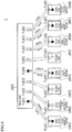
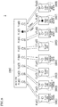
- FIGS. 6 to 8 are conceptual diagrams of one example of the chiller system 1 in which the connected number n of the chillers 100 is set to eight, showing a state in which the chillers 100 (1) to 100 (8) send the request for the defrost operation to the master chiller 100 (i) and the master chiller 100 (i) permits or inhibits the defrost operation to the chillers100 (1) to 100 (8).
- the total operation capacity of six chillers 100 out of the chillers 100 (1) to 100 (8) is sufficient with respect to the load capacity, accordingly, two chillers 100 (3) and 100 (5) are stopped while six chillers 100 (1), 100 (2), 100 (4) and 100 (6) to 100 (8) perform the heating operation. Specifically, out of the chillers 100 (1), 100 (2), 100 (4) and 100 (6) to 100 (8) that perform the heating operation, the chillers 100 (1), 100 (4) and 100 (6) to 100 (8) determine that the defrost operation is needed and send the request for the defrost operation to the master chiller 100 (i).
- the top two chillers 100 in request arrival order are the chiller 100 (1) and the chiller 100 (4), in this order.
- the priority of the remaining chillers 100 (6) to 100 (8) is in the order of the chiller 100 (6), the chiller 100 (8) and the chiller 100 (7), in descending order of the number of the requests for the defrost operation.
- the master chiller 100 (i) permits the defrost operation in arrival order to the two chillers 100 (1) and 100 (4) that have sent the request for the defrost operation earlier, and inhibits the three chillers 100 (6) to 100 (8) that have sent the request later than the two chillers 100 (1) and 100 (4) from performing the defrost operation.
- the master chiller 100 (i) permits the defrost operation, in descending order of the number of the requests for the defrost operation, to the two chillers 100 (6) and 100 (8) on standby that have sent a greater number of requests, and inhibits the chiller 100 (7) that has sent a smaller number of requests than the two chillers 100 (6) and 100 (8) from performing the defrost operation (i.e., the chiller 100 (7) is continuously in the standby state).
- the master chiller 100 (i) permits the defrost operation to the remaining one chiller 100 (7).
- FIG. 9 is a graph showing a temperature regulating capacity of the chiller system 1 and a timing chart of respective operation states of the chillers 100 (1) to 100 (8) in the example in FIGS. 6 to 8 .
- the term "Thermo-ON” means that the compressor 10 is being operated, and the “Thermo-OFF” means that the compressor 10 is being stopped.
- the "Defrost operation ON” means that the defrost operation is being operated, and the “Defrost operation OFF” means that the defrost operation is not being operated.
- the chillers 100 (1), 100 (2), 100 (4), and 100 (6) to 100 (8) in the thermo-ON state perform the heating operation when they are in the defrost operation OFF state. They perform the defrost operation when they are in the defrost operation ON state.
- the originally stopped chillers 100 (3) and 100 (5) are being stopped when they are in the thermo-OFF state, and perform the heating operation in the thermo-ON state.
- FIG. 10 is a flowchart showing steps of one example of operations for the defrost control by the master chiller (i) to the respective chillers 100 (1) to 100 (n).
- step S1 when two chillers 100 (3) and 100 (5) are stopped and six chillers 100 (1), 100 (2), 100 (4) and 100 (6) to 100 (8) perform the heating operation out of the eight chillers 100 (1) to 100 (8) (see ⁇ 1 in FIG. 9 ), the chillers 100 (1), 100 (2), 100 (4) and 100 (6) to 100 (8) performing the heating operation determine whether the defrost operation is needed or not (step S1).
- the chillers 100 (1), 100 (4) and 100 (6) to 100 (8) that need the defrost operation set respective defrost request flags FLa (1), FLa (4) and FLa (6) to FLa (8) to ON (see FIG. 6 ) so as to send the request for the defrost operation to the master chiller 100 (i) (step S2).
- the defrost request flags FLa (1) to FLa (8) and defrost permission flags FLb (1) to FLb (8) are in the OFF state in the initial state.
- the master chiller 100 sets, among the defrost permission flags FLb (1) to FLb (8) respectively corresponding to the chillers 100 (1) to 100 (8), the defrost permission flags FLb (1) and FLb (4) to ON (see FIG. 6 ) to the chillers 100 (chillers 100 (1) and 100 (4) in this example) in the arrival order of the requests for the defrost operation up to the permitted number m for simultaneous defrost operation (two chillers in this example), out of the chillers 100 (chillers 100 (1), 100 (4) and 100 (6) to 100 (8) in this example) that send the request for the defrost operation to the master chiller 100 (i).
- the master chiller 100 (i) permits the defrost operation to the chillers 100 (1) and 100 (4) corresponding to the permitted number (two chillers in this example) for simultaneous defrost operation in arrival order of the requests for the defrost operation (step S3).
- the two chillers 100 (1) and 100 (4) permitted to perform the defrost operation are switched from the heating operation to the defrost operation (step S4). Accordingly, the number of the chillers 100 performing the heating operation (six chillers) is reduced by two, thus becomes four (i.e., chillers 100 (2) and 100 (6) to 100 (8)), which results in reduction in the air conditioning capacity (see ⁇ 2 in FIG. 9 ). For this reason, the master chiller 100 (i) switches the two stopped chillers 100 (3) and 100 (5) in the thermo-OFF state to the thermo-ON state so that they perform the heating operation.
- the number of the chillers 100 performing the heating operation (four chillers) is increased by two, thus becomes six (i.e., chillers 100 (2), 100 (3), 100 (5) and 100 (6) to 100 (8)) (see ⁇ 3 in FIG. 9 ).
- step S5 While the chillers 100 (1) and 100 (4) are continuously performing the defrost operation (step S5: No), the chillers 100 (6) to 100 (8) on standby for the defrost operation send the request for the defrost operation to the master chiller 100 (i) in the predetermined cycle (step S6).
- step S6 when the frost is removed from the chillers 100 (1) and 100 (4) performing the defrost operation and the defrost operation is not necessary any more (step S5: Yes), the defrost operation is terminated (step S7) and the defrost request flags FLa (1) and FLa (4) are set to OFF.
- the master chiller 100 (i) sets the defrost permission flags FLb (1) and FLb (4) to OFF (see FIG. 7 ).
- the two chillers 100 (1) and 100 (4) that have set the defrost request flags FLa (1) and FLa (4) to OFF are returned from the defrost operation to the heating operation. Accordingly, the number of the chillers 100 performing the heating operation (six chillers) is increased by two, thus becomes eight (i.e., chillers 100 (1) to 100 (8)), which results in increase in the air conditioning capacity (see ⁇ 4 in FIG. 9 ). For this reason, the master chiller 100 (i) switches the two chillers 100 (3) and 100 (5), which are performing the heating operation in the thermo-ON state despite the originally stopped state, to the thermo-OFF state so that they are stopped.
- the number of the chillers 100 performing the heating operation is reduced by two, thus becomes six (i.e., chillers 100 (1), 100 (2), 100 (4) and 100 (6) to 100 (8)) (see ⁇ 5 in FIG. 9 ).
- step S10 the procedure advances to step S10 via step S8 (step S8: Yes) and step S9 (step S9: Yes), where the master chiller 100 (i) rearranges the priority of the chillers 100 (chillers 100 (6) to 100 (8) in this example) that send the request for the defrost operation to the master chiller 100 (i) in descending order of the number of the requests for the defrost operation. If the chillers 100 send the same number of the requests, the master chiller 100 (i) rearranges their priority in ascending order of the identification number (step S10).
- the priority of the chillers 100 (6) to 100 (8) is in the order of: the chiller (6); the chiller (8); and the chiller (7).
- the priority of the chillers 100 (6) to 100 (8) is in the order of the chiller 100 (6), the chiller 100 (8) and the chiller 100 (7).
- the priority of the chillers 100 (6) to 100 (8) is in the order of the chiller (6), the chiller (7) and the chiller (8), because the chiller 100 (8) has the identification number of "8" while the chiller 100 (7) has the identification number of "7".
- the master chiller 100 sets, among the defrost permission flags FLb (1) to FLb (8) respectively corresponding to the chillers 100 (1) to 100 (8), the defrost permission flags FLb (6) and FLb (8) to ON (see FIG.
- the master chiller 100 (i) permits the defrost operation to the chillers 100 (6) and 100 (8) corresponding to the permitted number (here, two chillers) for simultaneous defrost operation in descending order of the number of the requests for the defrost operation or in ascending order of the identification number in case of the chillers sending the same number of the requests (step S11).
- the two chillers 100 (6) and 100 (8) permitted to perform the defrost operation are switched from the heating operation to the defrost operation (step S4). Accordingly, the number of the chillers 100 performing the heating operation (six chillers) is reduced by two, thus becomes four (i.e., chillers 100 (1), 100 (2), 100 (4) and 100 (7)), which results in reduction in the air conditioning capacity (see ⁇ 6 in FIG. 9 ). For this reason, the master chiller 100 (i) switches the two stopped chillers 100 (3) and 100 (5) in the thermo-OFF state to the thermo-ON state so that they perform the heating operation. Accordingly, the number of the chillers 100 performing the heating operation (four chillers) is increased by two, thus becomes six (i.e., chillers 100 (1) to 100 (5) and 100 (7)) (see ⁇ 7 in FIG. 9 ).
- step S5 While the chillers 100 (6) and 100 (8) are continuously performing the defrost operation (step S5: No), the chiller 100 (7) on standby for the defrost operation sends the request for the defrost operation to the master chiller 100 (i) in the predetermined cycle (step S6).
- step S6 when the frost is removed from the chillers 100 (6) and 100 (8) performing the defrost operation and the defrost operation is not necessary any more (step S5: Yes), the defrost operation is terminated (step S7) and the defrost request flags FLa (6) and FLa (8) are set to OFF.
- the master chiller 100 (i) sets the defrost permission flags FLb (6) and FLb (8) to OFF (see FIG. 8 ).
- the two chillers 100 (6) and 100 (8) that have set the defrost request flags FLa (6) and FLa (8) to OFF are returned from the defrost operation to the heating operation. Accordingly, the number of the chillers 100 performing the heating operation (six chillers) is increased by two, thus becomes eight (i.e., chillers 100 (1) to 100 (8)), which results in increase in the air conditioning capacity (see ⁇ 8 in FIG. 9 ). For this reason, the master chiller 100 (i) switches the two chillers 100 (3) and 100 (5), which are performing the heating operation in the thermo-ON state despite the originally stopped state, to the thermo-OFF state so that they are stopped.
- the number of the chillers 100 performing the heating operation is reduced by two, thus becomes six (i.e., chillers 100 (1), 100 (2), 100 (4) and 100 (6) to 100 (8)) (see ⁇ 9 in FIG. 9 ).
- step S12 the procedure advances to step S12 via step S8 (step S8: Yes) and step S9 (step S9: No), where the master chiller 100 (i) sets, among the defrost permission flags FLb (1) to FLb (8) respectively corresponding to the chillers 100 (1) to 100 (8), the defrost permission flag FLb (7) to ON (see FIG. 8 ) to the remaining one chiller 100 (chiller 100 (7) in this example) that sends the request for the defrost operation to the master chiller 100 (i).
- the master chiller 100 (i) permits the defrost operation to the remaining one chiller 100 (7) (step S12).
- the one chiller 100 (7) permitted to perform the defrost operation is switched from the heating operation to the defrost operation (step S4). Accordingly, the number of the chillers 100 performing the heating operation (six chillers) is reduced by one, thus becomes five (i.e., chillers 100 (1), 100 (2), 100 (4), 100 (6) and 100 (8)), which results in reduction in the air conditioning capacity (see ⁇ 10 in FIG. 9 ). For this reason, the master chiller 100 (i) switches the one stopped chillers 100 (chiller 100 (3) in this example) in the thermo-OFF state to the thermo-ON state so that it performs the heating operation. Accordingly, the number of the chillers 100 performing the heating operation (five chillers) is increased by one, thus becomes six (i.e., chillers 100 (1) to 100 (4), 100 (6) and 100 (8)) (see ⁇ 11 in FIG. 9 ).
- step S5 when the frost is removed from the chiller 100 (7) performing the defrost operation and the defrost operation is not necessary any more (step S5: Yes), the defrost operation is terminated (step S7) and the defrost request flag FLa (7) is set to OFF.
- the master chiller 100 i) sets the defrost permission flag FLb (7) to OFF.
- the one chiller 100 (7) that has set the defrost request flag FLa (7) to OFF is returned from the defrost operation to the heating operation. Accordingly, the number of the chillers 100 performing the heating operation (six chillers) is increased by one, thus becomes seven (i.e., chillers 100 (1) to 100 (4) and 100 (6) to 100 (8)), which results in increase in the air conditioning capacity (see ⁇ 12 in FIG. 9 ). For this reason, the master chiller 100 (i) switches the one chiller 100 (3), which is performing the heating operation in the thermo-ON state despite the originally stopped state, to the thermo-OFF state so that it is stopped.
- the number of the chillers 100 performing the heating operation is reduced by one, thus becomes six (i.e., chillers 100 (1), 100 (2), 100 (4) and 100 (6) to 100 (8)) (see ⁇ 13 in FIG. 9 ).
- step S8: No When there remains no chiller 100 on standby for the defrost operation (step S8: No), the defrost control is terminated.
- the number of the chillers 100 is set to eight. However, the number of the chillers 100 is not limited thereto. The number of the chillers 100 may be in the range of two to seven or may be nine or more.
- next defrost operation is permitted to the chiller in descending order of the number of the requests.
- the priority is not limited thereto.
- the next defrost operation may be permitted to the chiller in descending order of the request time.
- the master chiller 100 (i) permits the next defrost operation to the chiller in ascending order of the identification number. However, the next defrost operation may be permitted to the chiller in descending order of the identification number.
- the control mechanism (master chiller 100 (i) in this example) permits the defrost operation to the chillers, out of the chillers 100 that have sent the request for the defrost operation, in arrival order of the requests for the defrost operation up to the predetermined number (permitted number m for simultaneous defrost operation).
- the chiller 100 on standby for the defrost operation sends the request for the defrost operation to the control mechanism (master chiller 100 (i) in this example) in the predetermined cycle.
- the master chiller 100 (i) permits the next defrost operation to the chiller in descending order of the number of the requests or the request time for the defrost operation.
- the master chiller 100 determines the priority of the chillers 100 on standby for the defrost operation when permitting the defrost operation in arrival order up to the predetermined number of chillers.
- the control mechanism (master chiller 100 (i) in this example) permits the next defrost operation in ascending order or in descending order of the identification number.
- the control mechanism permits the next defrost operation in ascending order or in descending order of the identification number.
- the present invention relates to a chiller system in which a plurality of heat pump chillers is connected to each other.
- the present invention is particularly suitable for determining the priority of the chillers on standby for the defrost operation when permitting the defrost operation to the chillers in arrival order up to the predetermined number of chillers.
Landscapes
- Engineering & Computer Science (AREA)
- Mechanical Engineering (AREA)
- General Engineering & Computer Science (AREA)
- Physics & Mathematics (AREA)
- Thermal Sciences (AREA)
- Combustion & Propulsion (AREA)
- Chemical & Material Sciences (AREA)
- Signal Processing (AREA)
- Fuzzy Systems (AREA)
- Mathematical Physics (AREA)
- Air Conditioning Control Device (AREA)
- Devices That Are Associated With Refrigeration Equipment (AREA)
- Human Computer Interaction (AREA)
Abstract
Description
- The present invention relates to a chiller system in which a plurality of heat pump chillers is connected to each other, the chillers regulating a temperature of a circulating liquid as a heat medium for temperature regulation by condensation heat or evaporation heat of a refrigerant.
- As a heat pump, a configuration is conventionally known, the configuration in which a defrost operation is performed, depending on conditions such as an outside air temperature, so as to remove frost that adheres to piping in a refrigerant-air heat exchanger that exchanges heat between a refrigerant and air when the refrigerant-air heat exchanger serves as an evaporator (see, for example, Patent Document 1). Specifically,
Patent Document 1 discloses a configuration in which, when the defrost operation is performed, the refrigerant is evaporated by heat absorbed from an engine coolant in an exhaust heat recovery unit by completely closing an expansion valve for an indoor heat exchanger so that no refrigerant flows into the indoor heat exchanger. - Similarly, in a heat pump chiller for regulating a temperature of a circulating liquid as a heat medium for temperature regulation (for example, for air conditioning) by condensation heat or evaporation heat of a refrigerant, the defrost operation is performed so as to remove frost that adheres to piping in a refrigerant-air heat exchanger. However, when the defrost operation is performed in a chiller system in which a plurality of heat pump chillers is connected to each other, the temperature of the circulating liquid is not regulated during defrost operation. Therefore, if the chillers not less than a predetermined number (especially, all of the chillers) perform the defrost operation at the same time, the regulation of the temperature of the circulating liquid cannot be sufficiently (or cannot be at all) preformed.
- In this regard,
Patent Document 2 discloses a configuration in which: when the respective chilling units (chillers) send a request for the defrost operation, a defrost permission signal is output to the chilling units (chillers) on a predetermined number basis so that only the predetermined number of chilling units (chillers) simultaneously perform the defrost operation (see paragraph [0104] of Patent Document 2); and when the number of the chilling units (chillers) that can simultaneously perform the defrost operation is not less than two, the defrost permission signal is output in response to the defrost request signal until the number of the chilling units (chillers) reaches the number of the chilling units (chillers) that can perform the defrost operation (see paragraph [0111] of Patent Document 2). That is,Patent Document 2 discloses the configuration in which the defrost operation is permitted to the chillers in arrival order up to the number of the chillers that can simultaneously perform the defrost operation. -
- [Patent Document 1]
JP 4257351 - [Patent Document 2]
JP H10-122604 A - However, although
Patent Document 2 discloses the configuration in which the defrost operation is permitted to the chillers in arrival order up to the number of the chillers that can simultaneously perform the defrost operation, it does not disclose the priority of the chillers on standby for the defrost operation. - In consideration of the above circumstances, an object of the present invention is to provide a chiller system in which a plurality of heat pump chillers is connected to each other, the chiller system capable of determining the priority of the chillers on standby for a defrost operation when the defrost operation is permitted to the chillers in arrival order up to a predetermined number of chillers.
- In consideration of the above problems, the present invention provides a chiller system including a plurality of heat pump chillers being connected to each other, the plurality of heat pump chillers regulating a temperature of a circulating liquid as a heat medium for temperature regulation by condensation heat or evaporation heat of a refrigerant. Any one of the plurality of chillers is designated as a master chiller. Out of the plurality of chillers, at least one chiller that needs a defrost operation sends a request for the defrost operation to the master chiller. The master chiller permits the defrost operation to the at least one chiller that has sent the request for the defrost operation in arrival order up to a predetermined number of chillers. At least one chiller on standby for the defrost operation sends the request for the defrost operation to the master chiller in a predetermined cycle. When there are multiple chillers that are on standby for the defrost operation, the master chiller permits a next defrost operation to one of the multiple chillers on standby in descending order of the number of the requests or a request time for the defrost operation.
- In an exemplary aspect of the present invention, when the chillers send the same number of the requests or have the same request time for the defrost operation, the master chiller permits the next defrost operation to one of the chillers in ascending order or in descending order of an identification number.
- The present invention also provides a chiller system including a plurality of heat pump chillers being connected to each other, the plurality of heat pump chillers regulating a temperature of a circulating liquid as a heat medium for temperature regulation by condensation heat or evaporation heat of a refrigerant, in which the chiller system further includes a control mechanism configured to control operations of the plurality of chillers. Out of the plurality of chillers, at least one chiller that needs the defrost operation sends a request for the defrost operation to the control mechanism. The control mechanism permits the defrost operation to the at least one chiller that has sent the request for the defrost operation in arrival order up to the predetermined number of chillers. At least one chiller on standby for the defrost operation sends the request for the defrost operation to the control mechanism in a predetermined cycle. When there are multiple chillers that are on standby for the defrost operation, the control mechanism permits the next defrost operation to one of the multiple chillers on standby in descending order of the number of the requests or the request time for the defrost operation.
- With the present invention providing a chiller system in which a plurality of heat pump chillers is connected to each other, it is possible to determine the priority of the chillers on standby for the defrost operation when the defrost operation is permitted to the chillers in arrival order up to a predetermined number of the chillers.
-
- [
FIG. 1 ]
FIG. 1 is a system diagram showing a schematic configuration of a chiller system according to an embodiment of the present invention. - [
FIG. 2 ]
FIG. 2 is a schematic block diagram showing one chiller in the chiller system. - [
FIG. 3 ]
FIG. 3 is a schematic block diagram showing a chiller that performs a cooling operation. - [
FIG. 4 ]
FIG. 4 is a schematic block diagram showing a chiller that performs a heating operation. - [
FIG. 5 ]
FIG. 5 is a schematic block diagram showing a chiller that performs a defrost operation. - [
FIG. 6 ]
FIG. 6 is a conceptual diagram of one example of the chiller system in which the number of the chillers is set to eight, showing a state in which the chillers send a request for the defrost operation to a master chiller and the master chiller permits or inhibits the defrost operation to the chillers. The diagram shows that the master chiller permits the defrost operation in arrival order to two chillers that have sent the request for the defrost operation earlier than the others, and inhibits three chillers that have sent the request later than the two chillers from performing the defrost operation. - [
FIG. 7 ]
FIG. 7 is a conceptual diagram of one example of the chiller system in which the number of the chillers is set to eight, showing a state in which the chillers send the request for the defrost operation to the master chiller and the master chiller permits or inhibits the defrost operation to the chillers. The diagram shows that, after termination of the defrost operation of the two chillers shown inFIG. 6 , the master chiller permits the defrost operation, in descending order of the number of requests for the defrost operation, to two chillers on standby that have sent a greater number of requests, and inhibits one chiller that have sent a smaller number of requests than the other two chillers from performing the defrost operation. - [
FIG. 8 ]
FIG. 8 is a conceptual diagram of one example of the chiller system in which the number of the chillers is set to eight, showing a state in which the chillers send the request for the defrost operation to the master chiller and the master chiller permits or inhibits the defrost operation to the chillers. The diagram shows that, after termination of the defrost operation of the two chillers shown inFIG. 7 , the master chiller permits the defrost operation to the remaining one chiller. - [
FIG. 9 ]
FIG. 9 is a graph showing a temperature regulating capacity of the chiller system and a timing chart of respective operation states of the chillers in the example inFIGS. 6 to 8 . - [
FIG. 10 ]
FIG. 10 is a flowchart showing steps of one example of operations for the defrost control by the master chiller to the respective chillers. - Hereinafter, an embodiment according to the present invention will be described with reference to the drawings.
-
FIG. 1 is a system diagram showing a schematic configuration of achiller system 1 according to an embodiment of the present invention. - In the
chiller system 1 shown inFIG. 1 , a plurality ofheat pump chillers 100 is connected in parallel. Hereinafter, a heat pump chiller is occasionally referred to, simply, as a chiller. - Specifically, the
chiller system 1 includes: the plurality of chillers 100 (1) to 100 (n) (n is an integer of ≥ 2); and a circulatingliquid circuit 200. Each of the chillers 100 (1) to 100 (n) has the same configuration. Accordingly, the rated output for each of the chillers 100 (1) to 100 (n) is set to the same value. Hereinafter, each of the chillers 100 (1) to 100 (n) is occasionally indicated simply with thereference numeral 100. - The
chiller system 1 further includes: the circulatingliquid circuit 200 that is installed in a temperature regulation target area (for example, an air conditioning target area, not shown) for circulating a circulating liquid as a heat medium for temperature regulation (for example, for air conditioning); and circulation pumps 300 (1) to 300 (n) respectively disposed corresponding to the chillers 100 (1) to 100 (n) in the circulatingliquid circuit 200 so as to circulate the circulating liquid in the circulatingliquid circuit 200. The circulation pumps 300 (1) to 300 (n) regulate the temperature of the circulating liquid that flows in the circulatingliquid circuit 200. Here, any circulating liquid can be used provided that it serves as the heat medium, and representative examples thereof include water. However, the circulating liquid is not limited thereto. For example, water containing antifreeze liquid can be used. - The circulating
liquid circuit 200 is constituted by: an inletmain pipe 210 to flow the circulating liquid toward the plurality of chillers100 (1) to 100 (n); inlet branch pipes 211 (1) to 211 (n) to divide and flow the circulating liquid from the inletmain pipe 210 into the respective chillers 100 (1) to 100 (n); an outletmain pipe 220 to flow the circulating liquid out of the plurality of chillers 100 (1) to 100 (n); and outlet branch pipes 221 (1) to 221 (n) to flow and join the circulating liquid from the plurality of chillers 100 (1) to 100 (n) to the outletmain pipe 220. - Specifically, the inlet branch pipes 211 (1) to 211 (n) each connect a branch portion of the inlet
main pipe 210 that corresponds to each chiller 100 (1) to 100 (n) and a circulating liquid flowing-in side of each chiller 100 (1) to 100 (n). The outlet branch pipes 221 (1) to 221 (n) each connect a circulating liquid flowing-out side of each chiller 100 (1) to 100 (n) and a confluence portion of the outletmain pipe 220 that corresponds to each chiller 100 (1) to 100 (n). On one side of each pair of the inlet branch pipes 211 (1) to 211 (n) and the outlet branch pipe 221 (1) to 221 (n) (in this example, on the side of the outlet branch pipes 221 (1) to 221 (n)), each circulation pump 300 (1) to 300 (n) is disposed to circulate the circulating liquid in the circulatingliquid circuit 200. - In the
chiller system 1 having the above configuration, the circulating liquid that is circulated by the circulation pumps 300 (1) to 300 (n) is divided and flows, from the inletmain pipe 210, into each chiller 100 (1) to 100 (n) via each inlet branch pipe 211 (1) to 211 (n), and the temperature of the circulating liquid is regulated by each chiller 100 (1) to 100 (n). The circulating liquid whose temperature is regulated is joined, from each chiller 100 (1) to 100 (n), to the outletmain pipe 220 via each outlet branch pipe 221 (1) to 221 (n), and is circulated in the temperature regulation target area (for example, the air conditioning target area) of the circulatingliquid circuit 200. The respective load sides of the inletmain pipe 210 and the outletmain pipe 220 are connected to each other, for example, via a heat exchanger not shown, and constitute a closed circuit. -
FIG. 2 is a schematic block diagram showing onechiller 100 in thechiller system 1. Note thatFIG. 2 shows oneinlet branch pipe 211 out of the inlet branch pipes 211 (1) to 211 (n), oneoutlet branch pipe 221 out of the outlet branch pipes 221 (1) to 221 (n), and onecirculation pump 300 out of the circulation pumps 300 (1) to 300 (n). - The
chiller 100 drives acompressor 10 that compresses a refrigerant so as to regulate the temperature of the circulating liquid by the condensation heat or the evaporation heat of the refrigerant. - That is, the
chiller 100 includes: thecompressor 10 that sucks and discharges the refrigerant; a refrigerant-air heat exchanger 20 that exchanges heat between the refrigerant and air (specifically, outside air); a refrigerant-airheat exchanger fan 30 for the refrigerant-air heat exchanger 20; anexpansion valve 40 that expands the refrigerant compressed by thecompressor 10; a refrigerant-circulatingliquid heat exchanger 50 that exchanges heat between the circulating liquid and the refrigerant; anengine 60 that drives thecompressor 10; and an engine exhaustheat recovery unit 70 that recovers exhaust heat of theengine 60. Thechiller 100 is capable of executing a heating operation, a cooling operation and a defrost operation as described later. In this example, theexpansion valve 40 is constituted by a closablefirst expansion valve 41 and a closablesecond expansion valve 42. - The
compressor 10 may be constituted by a plurality of compressors connected in parallel. Also, the refrigerant-air heat exchanger 20 may be constituted by a plurality of refrigerant-air heat exchangers connected in parallel. - Specifically, the
chiller 100 further includes: arefrigerant circuit 110 to circulate the refrigerant; acoolant path 120 to circulate an engine coolant for cooling theengine 60; acirculation pump 130 for thecoolant path 120; and acontrol device 140. - In the
refrigerant circuit 110, thecompressor 10, the refrigerant-air heat exchanger 20, the refrigerant-circulatingliquid heat exchanger 50, theexpansion valve 40 and the engine exhaustheat recovery unit 70 are disposed. - The
refrigerant circuit 110 includes: a four-way valve 111; abridge circuit 112; a high pressuregas refrigerant path 113a; a first low pressuregas refrigerant path 113b; a firstgas refrigerant path 113c; a firstrefrigerant path 113d; a high pressure liquidrefrigerant path 113e; a first low pressure gas-liquid two phaserefrigerant path 113f; a secondrefrigerant path 113g; a secondgas refrigerant path 113h; a second low pressure gas-liquid twophase refrigerant path 113i; and a second low pressuregas refrigerant path 113j. - The four-
way valve 111 is switched, in response to an instruction signal from thecontrol device 140, between a first connection state (state shown inFIG. 2 ) in which an inlet (lower side inFIG. 2 ) is connected to one connection port (left side inFIG. 2 ) and furthermore the other connection port (right side inFIG. 2 ) is connected to an outlet (upper side inFIG. 2 ), and a second connection state in which the inlet is connected to the other connection port and furthermore the one connection port is connected to the outlet. Thus, the four-way valve 111 can switch the flowing direction of the refrigerant. - The
bridge circuit 112 includes four check valves (afirst check valve 112a, asecond check valve 112b, athird check valve 112c and afourth check valve 112d), and is constituted by a firstcheck valve line 1121 including two check valves (thefirst check valve 112a and thesecond check valve 112b) and a secondcheck valve line 1122 including the remaining two check valves (thethird check valve 112c and thefourth check valve 112d). - The first
check valve line 1121 is constituted by thefirst check valve 112a and thesecond check valve 112b that are connected in series so that the refrigerant flows in the same direction. The secondcheck valve line 1122 is constituted by thethird check valve 112c and thefourth check valve 112d that are connected in series so that the refrigerant flows in the same direction. Furthermore, the firstcheck valve line 1121 and the secondcheck valve line 1122 are connected in parallel so that the refrigerant flows in the same direction. - In the
bridge circuit 112, a connection point between thefirst check valve 112a and thesecond check valve 112b is referred to as a first intermediate connection point P1, a connection point between thefirst check valve 112a and thethird check valve 112c is referred to as an outlet connection point P2, a connection point between thethird check valve 112c and thefourth check valve 112d is referred to as a second intermediate connection point P3, and a connection point between thesecond check valve 112b and thefourth check valve 112d is referred to as an inlet connection point P4. - The high pressure
gas refrigerant path 113a connects a discharge port of thecompressor 10 and the inlet of the four-way valve 111. The first low pressuregas refrigerant path 113b connects the outlet of the four-way valve 111 and a suction port of thecompressor 10. The firstgas refrigerant path 113c connects the one connection port of the four-way valve 111 and one connection port of the refrigerant-air heat exchanger 20. The firstrefrigerant path 113d connects the other connection port of the refrigerant-air heat exchanger 20 and the first intermediate connection point P1 of thebridge circuit 112. The high pressure liquidrefrigerant path 113e connects the outlet connection point P2 of thebridge circuit 112 and one side of the expansion valve 40 (specifically, thefirst expansion valve 41 and the second expansion valve 42). The first low pressure gas-liquid two phaserefrigerant path 113f connects the other side of thefirst expansion valve 41 constituting theexpansion valve 40 and the inlet connection point P4 of thebridge circuit 112. The secondrefrigerant path 113g connects the second intermediate connection point P3 of thebridge circuit 112 and one refrigerant connection port of the refrigerant-circulatingliquid heat exchanger 50. The secondgas refrigerant path 113h connects the other refrigerant connection port of the refrigerant-circulatingliquid heat exchanger 50 and the other connection port of the four-way valve 111. The second low pressure gas-liquid twophase refrigerant path 113i connects the other side of thesecond expansion valve 42 constituting theexpansion valve 40 and a refrigerant inlet of the engine exhaustheat recovery unit 70. The second low pressuregas refrigerant path 113j connects a refrigerant outlet of the engine exhaustheat recovery unit 70 and a confluence point P5 located in the middle of the first low pressuregas refrigerant path 113b. In the first low pressuregas refrigerant path 113b, the downstream side of the confluence point P5 (the side of the compressor 10) is referred to as a confluence path 113b1. - The respective opening degrees of the
first expansion valve 41 and thesecond expansion valve 42 can be adjusted in response to the instruction signal from thecontrol device 140. Thus, the amount of the refrigerant circulating in therefrigerant circuit 110 can be adjusted by thefirst expansion valve 41 and thesecond expansion valve 42. Specifically, thefirst expansion valve 41 and thesecond expansion valve 42 are configured by connecting a plurality of closable expansion valves in parallel. In this way, thefirst expansion valve 41 and thesecond expansion valve 42 can adjust the amount of the refrigerant circulating in therefrigerant circuit 110 by being combined as the expansion valve(s) to be opened. - In this embodiment, the
chiller 100 further includes anoil separator 81, anaccumulator 82 and areceiver 83. - The
oil separator 81 is disposed in the high pressuregas refrigerant path 113a, and separates a lubricant oil of thecompressor 10 contained in the refrigerant so as to return the separated lubricant oil to thecompressor 10 via avalve 81a (more specifically, a solenoid valve). Theaccumulator 82 is disposed in the confluence path 113b1 of the first low pressuregas refrigerant path 113b, and separates the liquid refrigerant that has not been completely evaporated by the refrigerant-circulatingliquid heat exchanger 50 serving as an evaporator or by the refrigerant-air heat exchanger 20 serving as an evaporator. Thereceiver 83 is disposed in the high pressure liquidrefrigerant path 113e, and temporarily stores the high pressure liquid refrigerant from thebridge circuit 112. - The
coolant path 120 constitutes the path for the engine coolant that cools theengine 60, and includes a first thermostattype switching valve 121, a second thermostattype switching valve 122, aradiator 123, anoutlet path 124a, aninlet path 124b, and afirst path 124c to afifth path 124g. - The
outlet path 124a connects an outlet of theengine 60 and an inlet (lower side inFIG. 2 ) of the first thermostattype switching valve 121. Theinlet path 124b connects an outlet of theradiator 123 and an inlet of theengine 60. Thefirst path 124c connects one outlet (upper side inFIG. 2 ) of the first thermostattype switching valve 121 and an inlet (left side inFIG. 2 ) of the second thermostattype switching valve 122. Thesecond path 124d connects the other outlet (right side inFIG. 2 ) of the first thermostattype switching valve 121 and an inlet of theradiator 123. Thethird path 124e connects one outlet (upper side inFIG. 2 ) of the second thermostattype switching valve 122 and a coolant inlet of the engine exhaustheat recovery unit 70. Thefourth path 124f connects the other outlet (right side inFIG. 2 ) of the second thermostattype switching valve 122 and a confluence point P6 located in the middle of theinlet path 124b. Thefifth path 124g connects a coolant outlet of the engine exhaustheat recovery unit 70 and a confluence point P7 located upstream of the confluence point P6 of theinlet path 124b. Thecirculation pump 130 is disposed in theinlet path 124b, between the inlet of theengine 60 and the confluence point P6. Thecirculation pump 130 circulates the engine coolant in thecoolant path 120 in response to the instruction signal from thecontrol device 140. The engine exhaustheat recovery unit 70 belongs to both of therefrigerant circuit 110 and thecoolant path 120. - The first thermostat
type switching valve 121 flows the engine coolant from theengine 60 toward the second thermostattype switching valve 122 when the temperature of the engine coolant is less than a predetermined first temperature (for example, 71°C). On the other hand, the first thermostattype switching valve 121 flows the engine coolant from theengine 60 toward theradiator 123 when the temperature of the engine coolant is not less than the first temperature. Thus, thecoolant path 120 can circulate the engine coolant toward the second thermostattype switching valve 122 when the temperature of the engine coolant is less than the first temperature, while it can circulate the engine coolant toward theradiator 123 when the temperature of the engine coolant is not less than the first temperature. - The second thermostat
type switching valve 122 flows the engine coolant from the first thermostattype switching valve 121 toward both of the engine exhaustheat recovery unit 70 and the confluence point P6 of theinlet path 124b when the temperature of the engine coolant is less than a predetermined second temperature (for example, 60°C) that is lower than the first temperature. On the other hand, the second thermostattype switching valve 122 flows the engine coolant from the first thermostattype switching valve 121 toward the engine exhaustheat recovery unit 70 when the temperature of the engine coolant is not less than the second temperature. Thus, thecoolant path 120 can circulate the engine coolant toward both of the engine exhaustheat recovery unit 70 and the confluence point P6 of theinlet path 124b when the temperature of the engine coolant is less than the second temperature, while it can circulate the engine coolant toward the engine exhaustheat recovery unit 70 when the temperature of the engine coolant is not less than the second temperature but less than the first temperature. - The temperature of the engine coolant can be detected by a temperature sensor (not shown) disposed in the
coolant path 120. - The
inlet branch pipe 211, which is a part of the circulatingliquid circuit 200, connects a circulating liquid inlet of the refrigerant-circulatingliquid heat exchanger 50 and a branch portion of the inlet main pipe 210 (seeFIG. 1 ) corresponding to thechiller 100. Theoutlet branch pipe 221, which is a part of the circulatingliquid circuit 200, connects a circulating liquid outlet of the refrigerant-circulatingliquid heat exchanger 50 and a confluence portion of the outlet main pipe 220 (seeFIG. 1 ) corresponding to thechiller 100. The refrigerant-circulatingliquid heat exchanger 50 belongs to both of therefrigerant circuit 110 and the circulatingliquid circuit 200. - The
compressor 10 is connected to theengine 60 via a clutch 11. The clutch 11 switches, in response to the instruction signal from thecontrol device 140, between a connection state in which the drive force is transmitted from theengine 60 to thecompressor 10 and a block state in which the transmission of the drive force from theengine 60 to thecompressor 10 is blocked. - The
chiller 100 further includes afirst pressure sensor 151, afirst temperature sensor 161, asecond pressure sensor 152, asecond temperature sensor 162 and arotation speed sensor 170. - The
first pressure sensor 151 and thefirst temperature sensor 161 are disposed in the confluence path 113b1, and detect respectively the pressure and the temperature of the refrigerant in the confluence path 113b1. Thesecond pressure sensor 152 and thesecond temperature sensor 162 are disposed in the second low pressuregas refrigerant path 113j, and detect respectively the pressure and the temperature of the refrigerant in the second low pressuregas refrigerant path 113j. Therotation speed sensor 170 is disposed in theengine 60, and detects the rotational speed of theengine 60. - The circulating
liquid circuit 200 includes an influent circulatingliquid temperature sensor 231 and an effluent circulatingliquid temperature sensor 232. - Specifically, the influent circulating
liquid temperature sensor 231 is disposed in theinlet branch pipe 211, and detects the temperature of the circulating liquid that flows into the refrigerant-circulating liquid heat exchanger 50 (more specifically, the circulating liquid in the inlet branch pipe 211). The effluent circulatingliquid temperature sensor 232 is disposed in theoutlet branch pipe 221, and detects the temperature of the circulating liquid that flows out of the refrigerant-circulating liquid heat exchanger 50 (more specifically, the circulating liquid in the outlet branch pipe 221). - The
control device 140 controls, according to detection signals from various sensors, driving of therefrigerant circuit 110, thecoolant path 120 and the circulatingliquid circuit 200. Thus, thechiller 100 can adjust the temperature of the circulating liquid that flows in the circulatingliquid circuit 200. - Specifically, the
control device 140 causes thecompressor 10 to compress the refrigerant that is sucked from the first low pressuregas refrigerant path 113b and to discharge the compressed refrigerant to the high pressuregas refrigerant path 113a. When the cooling operation to cool the circulating liquid in the circulatingliquid circuit 200 is performed, thecontrol device 140 makes the four-way valve 111 a first connection state in which the high pressuregas refrigerant path 113a is communicated with the firstgas refrigerant path 113c and furthermore the secondgas refrigerant path 113h is communicated with the first low pressuregas refrigerant path 113b. Also, when the heating operation to heat the circulating liquid in the circulatingliquid circuit 200 is performed, thecontrol device 140 makes the four-way valve 111 a second connection state in which the high pressuregas refrigerant path 113a is communicated with the secondgas refrigerant path 113h and furthermore the firstgas refrigerant path 113c is communicated with the first low pressuregas refrigerant path 113b. - The refrigerant-
air heat exchanger 20 serves as a condenser to cause the refrigerant to release heat and liquefy during cooling operation, and serves as an evaporator to cause the refrigerant to absorb heat and vaporize during heating operation. The refrigerant-circulatingliquid heat exchanger 50 serves as a cooler to cause the refrigerant to absorb heat and cool the circulating liquid during cooling operation, and serves as a heater to cause the refrigerant to release heat and heat the circulating liquid during heating operation. The engine exhaustheat recovery unit 70 serves as an evaporator to cause the refrigerant to absorb heat and vaporize. - The
first expansion valve 41 and thesecond expansion valve 42 are arranged, in parallel, downstream of thebridge circuit 112. In response to the instruction signal from thecontrol device 140, thefirst expansion valve 41 adjusts the flow rate of the refrigerant that flows toward the refrigerant-circulatingliquid heat exchanger 50 via thebridge circuit 112 during cooling operation, and adjusts the flow rate of the refrigerant that flows toward the refrigerant-air heat exchanger 20 via thebridge circuit 112 during heating operation. Thesecond expansion valve 42 adjusts, in response to the instruction signal from thecontrol device 140, the flow rate of the refrigerant that flows toward the engine exhaustheat recovery unit 70. - The
control device 140 includes aprocessor 141 constituted of a microcomputer such as a CPU (central processing unit), and amemory 142 including a non-volatile memory such as a ROM (read only memory) and a volatile memory such as a RAM (random access memory). - In the
control device 140, theprocessor 141 executes a control program previously stored in the ROM of thememory 142 by loading the control program on the RAM of thememory 142. Thus, operations of the respective component elements are controlled. - With the
chiller 100 as described above, it is possible to adjust the temperature of the circulating liquid that flows in the circulatingliquid circuit 200 by performing appropriately the cooling operation or the heating operation. - First, the cooling operation performed by the
chiller 100 will be described with reference toFIG. 3 . Next, the heating operation performed by thechiller 100 will be described with reference toFIG. 4 . -
FIG. 3 is a schematic block diagram showing thechiller 100 that performs the cooling operation. - When the
chiller 100 performs the cooling operation, thecontrol device 140 switches the four-way valve 111 to the first connection state in which the high pressuregas refrigerant path 113a is communicated with the firstgas refrigerant path 113c and furthermore the secondgas refrigerant path 113h is communicated with the first low pressuregas refrigerant path 113b. In this way, the refrigerant in a state of high pressure gas (hereinafter referred to as the "high pressure gas refrigerant") that is discharged from thecompressor 10 flows into the refrigerant-air heat exchanger 20 via theoil separator 81. - The temperature of the high pressure gas refrigerant that flows into the refrigerant-
air heat exchanger 20 is higher than the temperature of the air that passes through the refrigerant-air heat exchanger 20. For this reason, the heat is transferred from the high pressure gas refrigerant to the air. As a result, the high pressure gas refrigerant loses the condensation heat and liquefies, thus becomes the refrigerant in a state of a high pressure liquid (hereinafter referred to as the "high pressure liquid refrigerant"). That is, in the cooling operation, the refrigerant-air heat exchanger 20 serves as a condenser of the refrigerant, in which the high pressure gas refrigerant releases heat. - The high pressure liquid refrigerant flows from the refrigerant-
air heat exchanger 20 to the first intermediate connection point P1 of thebridge circuit 112 via the firstrefrigerant path 113d. Since the first intermediate connection point P1 is located on the outlet side of thesecond check valve 112b and on the inlet side of thefirst check valve 112a, the high pressure liquid refrigerant does not flow to thesecond check valve 112b and thethird check valve 112c, but flows to the high pressure liquidrefrigerant path 113e from the first intermediate connection point P1, via thefirst check valve 112a and the outlet connection point P2. - When the
control device 140 performs the cooling operation, it opens thefirst expansion valve 41 and closes thesecond expansion valve 42, so that the high pressure liquid refrigerant flows through thefirst expansion valve 41 but does not flow through thesecond expansion valve 42. Thus, the high pressure liquid refrigerant passes through thefirst expansion valve 41 via thereceiver 83 disposed in the high pressure liquidrefrigerant path 113e. - When passing through the
first expansion valve 41, the high pressure liquid refrigerant expands and becomes a refrigerant in a state of a low pressure gas-liquid two phase (hereinafter referred to as the "low pressure gas-liquid two phase refrigerant"). The low pressure gas-liquid two phase refrigerant flows from the first low pressure gas-liquid two phaserefrigerant path 113f to the inlet connection point P4 of thebridge circuit 112. The inlet connection point P4 is located on the inlet side of thesecond check valve 112b and thefourth check valve 112d. However, as described above, the high pressure liquid refrigerant flows through the first intermediate connection point P1 and the outlet connection point P2. For this reason, the low pressure gas-liquid two phase refrigerant does not flow to thesecond check valve 112b and thethird check valve 112c because of the pressure difference from the high pressure liquid refrigerant that flows through the first intermediate connection point P1 and the outlet connection point P2. The low pressure gas-liquid two phase refrigerant flows from the inlet connection point P4 to the refrigerant-circulatingliquid heat exchanger 50 via thefourth check valve 112d, the second intermediate connection point P3 and the secondrefrigerant path 113g. - The temperature of the low pressure gas-liquid two phase refrigerant that flows on the side of the
refrigerant circuit 110 relative to the refrigerant-circulatingliquid heat exchanger 50 is lower than the temperature of the circulating liquid that flows on the side of the circulatingliquid circuit 200 relative to the refrigerant-circulatingliquid heat exchanger 50. For this reason, the heat is transferred from the circulating liquid to the low pressure gas-liquid two phase refrigerant. As a result, the low pressure gas-liquid two phase refrigerant obtains the evaporation heat and vaporizes, thus becomes the refrigerant in a state of a low pressure gas (hereinafter referred to as the "low pressure gas refrigerant"). On the other hand, the circulating liquid is cooled by the heat absorbing action of the refrigerant. That is, in the cooling operation, the refrigerant-circulatingliquid heat exchanger 50 serves as a cooler of the circulating liquid, in which the low pressure gas-liquid two phase refrigerant absorbs heat. - After that, the low pressure gas refrigerant flows from the refrigerant-circulating
liquid heat exchanger 50 to the secondgas refrigerant path 113h. At this time, thecontrol device 140 communicates the secondgas refrigerant path 113h with the first low pressuregas refrigerant path 113b by the four-way valve 111. Thus, the low pressure gas refrigerant is sucked into thecompressor 10 via theaccumulator 82 disposed in the first low pressuregas refrigerant path 113b. - In the
chiller 100, the above-described series of operations as the cooling operation are repeatedly performed. -
FIG. 4 is a schematic block diagram showing thechiller 100 that performs the heating operation. - When the
chiller 100 performs the heating operation, thecontrol device 140 switches the four-way valve 111 to the second connection state in which the high pressuregas refrigerant path 113a is communicated with the secondgas refrigerant path 113h and furthermore the firstgas refrigerant path 113c is communicated with the first low pressuregas refrigerant path 113b. In this way, the high pressure gas refrigerant that is discharged from thecompressor 10 flows into the refrigerant-circulatingliquid heat exchanger 50 via theoil separator 81. - The temperature of the high pressure gas refrigerant that flows on the side of the
refrigerant circuit 110 relative to the refrigerant-circulatingliquid heat exchanger 50 is higher than the temperature of the circulating liquid that flows on the side of the circulatingliquid circuit 200 relative to the refrigerant-circulatingliquid heat exchanger 50. For this reason, the heat is transferred from the high pressure gas refrigerant to the circulating liquid. As a result, the high pressure gas refrigerant loses the condensation heat and liquefies, thus becomes the high pressure liquid refrigerant. On the other hand, the circulating liquid is heated by the heat releasing action of the refrigerant. That is, in the heating operation, the refrigerant-circulatingliquid heat exchanger 50 serves as a heater of the circulating liquid, in which the high pressure gas refrigerant releases heat. - The high pressure liquid refrigerant flows from the refrigerant-circulating
liquid heat exchanger 50 to the second intermediate connection point P3 of thebridge circuit 112 via the secondrefrigerant path 113g. Since the second intermediate connection point P3 is located on the inlet side of thethird check valve 112c and on the outlet side of thefourth check valve 112d, the high pressure liquid refrigerant does not flow to thefirst check valve 112a and thefourth check valve 112d, but flows to the high pressure liquidrefrigerant path 113e from the second intermediate connection point P3, via thethird check valve 112c and the outlet connection point P2. - When the
control device 140 performs the heating operation, it opens thefirst expansion valve 41 and closes thesecond expansion valve 42, so that the high pressure liquid refrigerant flows through thefirst expansion valve 41 but does not flow through thesecond expansion valve 42. Thus, the high pressure liquid refrigerant passes through thefirst expansion valve 41 via thereceiver 83 disposed in the high pressure liquidrefrigerant path 113e. - When passing through the
first expansion valve 41, the high pressure liquid refrigerant expands and becomes the low pressure gas-liquid two phase refrigerant. The low pressure gas-liquid two phase refrigerant flows from the first low pressure gas-liquid two phaserefrigerant path 113f to the inlet connection point P4 of thebridge circuit 112. The inlet connection point P4 is located on the inlet side of thesecond check valve 112b and thefourth check valve 112d. However, as described above, the high pressure liquid refrigerant flows through the second intermediate connection point P3 and the outlet connection point P2. For this reason, the low pressure gas-liquid two phase refrigerant does not flow to thefourth check valve 112d and thefirst check valve 112a because of the pressure difference from the high pressure liquid refrigerant that flows through the second intermediate connection point P3 and the outlet connection point P2. The low pressure gas-liquid two phase refrigerant flows from the inlet connection point P4 to the refrigerant-air heat exchanger 20 via thesecond check valve 112b and the firstrefrigerant path 113d. - The temperature of the low pressure gas-liquid two phase refrigerant that flows through the refrigerant-
air heat exchanger 20 is lower than the temperature of the air that passes through the refrigerant-air heat exchanger 20. For this reason, the heat is transferred from the air to the low pressure gas-liquid two phase refrigerant. As a result, the low pressure gas-liquid two phase refrigerant obtains the evaporation heat and vaporizes, thus becomes the low pressure gas refrigerant. That is, in the heating operation, the refrigerant-air heat exchanger 20 serves as an evaporator of the refrigerant, in which the low pressure gas-liquid two phase refrigerant absorbs heat. - After that, the low pressure gas refrigerant flows from the refrigerant-
air heat exchanger 20 to the firstgas refrigerant path 113c. At this time, thecontrol device 140 communicates the firstgas refrigerant path 113c with the first low pressuregas refrigerant path 113b by the four-way valve 111. Thus, the low pressure gas refrigerant is sucked into thecompressor 10 via theaccumulator 82 disposed in the first low pressuregas refrigerant path 113b. - In the
chiller 100, the above-described series of operations as the heating operation are repeatedly performed. - During heating operation, the low pressure gas-liquid two phase refrigerant is supplied to the refrigerant-
air heat exchanger 20, thus piping in the refrigerant-air heat exchanger 20 is cooled. In this case, frost may adheres to the piping in the refrigerant-air heat exchanger 20 depending on conditions such as an outside air temperature. Then, thechiller 100 performs the defrost operation. - Next, the defrost operation performed by the
chiller 100 will be described with reference toFIG. 5 . -
FIG. 5 is a schematic block diagram showing thechiller 100 that performs the defrost operation. - When the
chiller 100 performs the defrost operation, thecontrol device 140 switches, as in the cooling operation, the four-way valve 111 to the first connection state in which the high pressuregas refrigerant path 113a is communicated with the firstgas refrigerant path 113c and furthermore the secondgas refrigerant path 113h is communicated with the first low pressuregas refrigerant path 113b. In this way, the high pressure gas refrigerant that is discharged from thecompressor 10 flows into the refrigerant-air heat exchanger 20 via theoil separator 81. - The high pressure gas refrigerant that flows through the refrigerant-
air heat exchanger 20 loses, as in the cooling operation, the condensation heat and liquefies, thus becomes the high pressure liquid refrigerant. That is, in the defrost operation, the refrigerant-air heat exchanger 20 serves as a condenser of the refrigerant, in which the high pressure gas refrigerant releases heat. - Similarly to the cooling operation, the high pressure liquid refrigerant flows from the refrigerant-
air heat exchanger 20 to the high pressure liquidrefrigerant path 113e via the firstrefrigerant path 113d, and the first intermediate connection point P1, thefirst check valve 112a and the outlet connection point P2 of thebridge circuit 112. - When the
control device 140 performs the defrost operation, it opens thesecond expansion valve 42 and closes thefirst expansion valve 41, so that the high pressure liquid refrigerant flows through thesecond expansion valve 42 but does not flow through thefirst expansion valve 41. Thus, the high pressure liquid refrigerant passes through thesecond expansion valve 42 via thereceiver 83 disposed in the high pressure liquidrefrigerant path 113e. - When passing through the
second expansion valve 42, the high pressure liquid refrigerant expands and becomes the low pressure gas-liquid two phase refrigerant. The low pressure gas-liquid two phase refrigerant flows from the second low pressure gas-liquid twophase refrigerant path 113i to the engine exhaustheat recovery unit 70. - The temperature of the low pressure gas-liquid two phase refrigerant that flows on the side of the
refrigerant circuit 110 relative to the engine exhaustheat recovery unit 70 is lower than the temperature of the engine coolant that flows on the side of thecoolant path 120 relative to the engine exhaustheat recovery unit 70. For this reason, the heat is transferred from the engine coolant to the low pressure gas-liquid two phase refrigerant. As a result, the low pressure gas-liquid two phase refrigerant obtains the evaporation heat and vaporizes, thus becomes the low pressure gas refrigerant. That is, in the defrost operation, the engine exhaustheat recovery unit 70 serves as an evaporator of the refrigerant, in which the low pressure gas-liquid two phase refrigerant absorbs heat. - After that, the low pressure gas refrigerant flows from the engine exhaust
heat recovery unit 70, and is sucked into thecompressor 10 via the second low pressuregas refrigerant path 113j, the confluence point P5 of the first low pressuregas refrigerant path 113b, the confluence path 113b1, and theaccumulator 82. - In the
chiller 100, the above-described series of operations as the defrost operation are repeatedly performed. - In the defrost operation, the high pressure gas refrigerant is supplied to the refrigerant-
air heat exchanger 20, thus, the piping in the refrigerant-air heat exchanger 20 is heated. As a result, frost that adheres to the refrigerant-air heat exchanger 20 is removed by the heating operation. Furthermore, in the defrost operation, since the low pressure gas-liquid two phase refrigerant does not flow to the refrigerant-circulatingliquid heat exchanger 50, the decrease in the temperature of the circulating liquid according to evaporation of the refrigerant does not occur. - In the
chiller system 1 in which the plurality of chillers 100 (1) to 100 (n) is connected to each other, when performing the defrost operation so as to remove frost that adheres to the piping in the refrigerant-air heat exchanger 20, the temperature of the circulating liquid is not regulated (i.e., the heating operation is not performed) during defrost operation. Therefore, if thechillers 100 not less than a predetermined number (especially, all of the chillers 100 (1) to 100 (n)) perform the defrost operation at the same time, the regulation of the temperature of the circulating liquid cannot be sufficiently (or cannot be at all) preformed. - In this regard, in the conventional chiller system as described above, when the respective chillers send the request for the defrost operation, only the predetermined number of chillers are permitted to simultaneously perform the defrost operation, and when the number of chillers that can simultaneously perform the defrost operation is not less than two, the defrost operation is permitted to the chillers in arrival order up to the number of the chillers that can simultaneously perform the defrost operation (see Patent Document 2). However, the conventional system does not have a configuration to determine the priority of the chillers on standby for the defrost operation.
- In consideration of the above circumstances, the
chiller system 1 according to this embodiment includes a control mechanism to control the operation of each chiller 100 (1) to 100 (n) as described below. - That is, in this embodiment, the control mechanism is an aggregate of the
respective control devices 140 of the chillers 100 (1) to 100 (n). The control devices 140 (1) to 140 (n) are connected to each other in order to communicate with each other. In thechiller system 1, one chiller is designated as a master chiller (i) (i is an integer of from 1 to n) out of the plurality of chillers 100 (1) to 100 (n). Note that the control mechanism may be a control device that integrally controls the chillers 100 (1) to 100 (n) and that is provided separated from the chillers 100 (1) to 100 (n). - The chillers 100 (1) to 100 (n) perform the defrost operation for defrost control to remove frost that adheres to the refrigerant-
air heat exchanger 20. Thechiller 100 performing the heating operation determines, for example, that the defrost operation is required when the continuous execution time of the heating operation exceeds a predetermined time. The defrost control is prepared to address a case in which it is determined that the defrost operation is required. The defrost control is to cause thechillers 100, which determine that the defrost operation is needed while performing the heating operation, to perform the defrost operation until the number of the chillers to perform reaches a permitted number to perform simultaneously the defrost operation, without causing thechillers 100 that are beyond the predetermined number of the chillers (i.e., permitted number of the chillers to perform simultaneously the defrost operation) to perform the defrost operation. - In this embodiment, the permitted number of the chillers to perform simultaneously the defrost operation can be set to the number adding one chiller to the value that is obtained by: dividing the number, which is obtained by subtracting one chiller from the number of the
connected chillers 100, by a permission reference number (in this example, four chillers) that serves as the reference for permitting the defrost operation; and rounding the above-obtained value down to the nearest whole number . - That is, when the connected number is represented as n (n ≥ 2) and the permission reference number is represented as c, the permitted number m for simultaneous defrost operation can be calculated by the following expression (1):

- For example, in the case where the permission reference number c is set to 4, when the connected number n is in the range of not less than 2 to not more than 4, the permitted number m for simultaneous defrost operation is 1. When the connected number n is in the range of not less than 5 to not more than 8, the permitted number m for simultaneous defrost operation is 2.
- When the plurality of chillers 100 (1) to 100 (n) (servant chillers and the master chiller 100 (i)) determines that the defrost operation is required, the
chillers 100 that need the defrost operation send the request for the defrost operation (specifically, transmit a signal to request the defrost operation) to the master chiller 100 (i) (specifically, the control device 140(i)). If thechiller 100 that sends the request for the defrost operation is the master chiller 100 (i) itself, the master chiller 100 (i) sends the request for the defrost operation to itself. - Also, the master chiller 100 (i) permits the defrost operation (specifically, transmits a signal to permit the defrost operation) to the chillers, out of the
chillers 100 that have sent the request for the defrost operation to the master chiller 100 (i), in arrival order of the requests up to the permitted number m for simultaneous defrost operation. If thechiller 100 that receives the permission of the defrost operation is the master chiller 100 (i) itself, the master chiller 100 (i) receives the permission of the defrost operation. - For example, when the connected number n of the
chillers 100 is set to eight, and when the arrival of the request for the defrost operation from each chiller 100 (1), 100 (4) and 100 (6) to 100 (8) to the master chiller 100 (i) is in the order of: the chiller 100 (1); the chiller 100 (4); the chiller 100 (6); the chiller 100 (7); and the chiller 100 (8), the master chiller 100 (i) permits the defrost operation to the chiller 100 (1) and the chiller 100 (4) in arrival order of the requests up to the permitted number m for simultaneous defrost operation (in this example, two chillers). - Also, in the chillers 100 (1) to 100 (n), the
chiller 100 on standby for the defrost operation sends the request for the defrost operation (specifically, transmit the signal to request the defrost operation) to the master chiller 100 (i) in a predetermined cycle (specifically, at each processing time). - Here, the
chiller 100 on standby means the chiller that sends the request for the defrost operation to the master chiller 100 (i) while the master chiller 100 (i) does not permit the defrost operation (i.e., inhibits the defrost operation). - When a plurality of
chillers 100 on standby for the defrost operation exists, the master chiller 100 (i) permits a next defrost operation in descending order of the number of the requests or the request time for the defrost operation (the number of the requests in the example shown inFIGS. 6 to 10 described later). Here, the number of the requests for the defrost operation means the total number of the requests for the defrost operation by thechiller 100 that needs the defrost operation from the first request for the defrost operation to the latest permission determination of the defrost operation by the master chiller 100 (i). Also, the request time for the defrost operation means the total request time from the first request for the defrost operation by thechiller 100 that needs the defrost operation to the latest permission determination of the defrost operation by the master chiller 100 (i). - Identification numbers that differ from one another (in this example, 1 to n) are respectively given to the chillers 100 (1) to 100 (n). When the
chillers 100 send the same number of the requests or have the same request time for the defrost operation, the master chiller 100 (i) permits the next defrost operation in ascending order or in descending order of the identification number (in ascending order in the example shown inFIGS. 6 to 10 ). -
FIGS. 6 to 8 are conceptual diagrams of one example of thechiller system 1 in which the connected number n of thechillers 100 is set to eight, showing a state in which the chillers 100 (1) to 100 (8) send the request for the defrost operation to the master chiller 100 (i) and the master chiller 100 (i) permits or inhibits the defrost operation to the chillers100 (1) to 100 (8). - In the example shown in
FIGS. 6 to 8 , the total operation capacity of sixchillers 100 out of the chillers 100 (1) to 100 (8) is sufficient with respect to the load capacity, accordingly, two chillers 100 (3) and 100 (5) are stopped while six chillers 100 (1), 100 (2), 100 (4) and 100 (6) to 100 (8) perform the heating operation. Specifically, out of the chillers 100 (1), 100 (2), 100 (4) and 100 (6) to 100 (8) that perform the heating operation, the chillers 100 (1), 100 (4) and 100 (6) to 100 (8) determine that the defrost operation is needed and send the request for the defrost operation to the master chiller 100 (i). Among such chillers that have sent the request for the defrost operation, the top twochillers 100 in request arrival order are the chiller 100 (1) and the chiller 100 (4), in this order. The priority of the remaining chillers 100 (6) to 100 (8) is in the order of the chiller 100 (6), the chiller 100 (8) and the chiller 100 (7), in descending order of the number of the requests for the defrost operation. - That is, in
FIG. 6 , the master chiller 100 (i) permits the defrost operation in arrival order to the two chillers 100 (1) and 100 (4) that have sent the request for the defrost operation earlier, and inhibits the three chillers 100 (6) to 100 (8) that have sent the request later than the two chillers 100 (1) and 100 (4) from performing the defrost operation. - In
FIG. 7 , after termination of the defrost operation of the two chillers 100 (1) and 100 (4) shown inFIG. 6 , the master chiller 100 (i) permits the defrost operation, in descending order of the number of the requests for the defrost operation, to the two chillers 100 (6) and 100 (8) on standby that have sent a greater number of requests, and inhibits the chiller 100 (7) that has sent a smaller number of requests than the two chillers 100 (6) and 100 (8) from performing the defrost operation (i.e., the chiller 100 (7) is continuously in the standby state). - Also, in
FIG. 8 , after termination of the defrost operation of the two chillers 100 (6) and 100 (8) shown inFIG. 7 , the master chiller 100 (i) permits the defrost operation to the remaining one chiller 100 (7). -
FIG. 9 is a graph showing a temperature regulating capacity of thechiller system 1 and a timing chart of respective operation states of the chillers 100 (1) to 100 (8) in the example inFIGS. 6 to 8 . - In
FIG. 9 , the term "Thermo-ON" means that thecompressor 10 is being operated, and the "Thermo-OFF" means that thecompressor 10 is being stopped. Also, the "Defrost operation ON" means that the defrost operation is being operated, and the "Defrost operation OFF" means that the defrost operation is not being operated. In the example shown inFIGS. 6 to 9 , the chillers 100 (1), 100 (2), 100 (4), and 100 (6) to 100 (8) in the thermo-ON state perform the heating operation when they are in the defrost operation OFF state. They perform the defrost operation when they are in the defrost operation ON state. Furthermore, the originally stopped chillers 100 (3) and 100 (5) are being stopped when they are in the thermo-OFF state, and perform the heating operation in the thermo-ON state. - Hereinafter, the operation of the master chiller 100 (i) to control each chillers 100 (1) to 100 (n) will be described with reference to the example shown in
FIGS. 6 to 9 . -
FIG. 10 is a flowchart showing steps of one example of operations for the defrost control by the master chiller (i) to the respective chillers 100 (1) to 100 (n). - In the
chiller system 1, when two chillers 100 (3) and 100 (5) are stopped and six chillers 100 (1), 100 (2), 100 (4) and 100 (6) to 100 (8) perform the heating operation out of the eight chillers 100 (1) to 100 (8) (see α1 inFIG. 9 ), the chillers 100 (1), 100 (2), 100 (4) and 100 (6) to 100 (8) performing the heating operation determine whether the defrost operation is needed or not (step S1). According to determination results, when five chillers 100 (1), 100 (4) and 100 (6) to 100 (8) need the defrost operation out of the six chillers 100 (1), 100 (2), 100 (4) and 100 (6) to 100 (8) performing the heating operation, the chillers 100 (1), 100 (4) and 100 (6) to 100 (8) that need the defrost operation set respective defrost request flags FLa (1), FLa (4) and FLa (6) to FLa (8) to ON (seeFIG. 6 ) so as to send the request for the defrost operation to the master chiller 100 (i) (step S2). Here, the defrost request flags FLa (1) to FLa (8) and defrost permission flags FLb (1) to FLb (8) (described later) are in the OFF state in the initial state. - Next, the master chiller 100 (i) sets, among the defrost permission flags FLb (1) to FLb (8) respectively corresponding to the chillers 100 (1) to 100 (8), the defrost permission flags FLb (1) and FLb (4) to ON (see
FIG. 6 ) to the chillers 100 (chillers 100 (1) and 100 (4) in this example) in the arrival order of the requests for the defrost operation up to the permitted number m for simultaneous defrost operation (two chillers in this example), out of the chillers 100 (chillers 100 (1), 100 (4) and 100 (6) to 100 (8) in this example) that send the request for the defrost operation to the master chiller 100 (i). Thus, the master chiller 100 (i) permits the defrost operation to the chillers 100 (1) and 100 (4) corresponding to the permitted number (two chillers in this example) for simultaneous defrost operation in arrival order of the requests for the defrost operation (step S3). - Then, the two chillers 100 (1) and 100 (4) permitted to perform the defrost operation are switched from the heating operation to the defrost operation (step S4). Accordingly, the number of the
chillers 100 performing the heating operation (six chillers) is reduced by two, thus becomes four (i.e., chillers 100 (2) and 100 (6) to 100 (8)), which results in reduction in the air conditioning capacity (see α2 inFIG. 9 ). For this reason, the master chiller 100 (i) switches the two stopped chillers 100 (3) and 100 (5) in the thermo-OFF state to the thermo-ON state so that they perform the heating operation. Accordingly, the number of thechillers 100 performing the heating operation (four chillers) is increased by two, thus becomes six (i.e., chillers 100 (2), 100 (3), 100 (5) and 100 (6) to 100 (8)) (see α3 inFIG. 9 ). - Next, while the chillers 100 (1) and 100 (4) are continuously performing the defrost operation (step S5: No), the chillers 100 (6) to 100 (8) on standby for the defrost operation send the request for the defrost operation to the master chiller 100 (i) in the predetermined cycle (step S6). On the other hand, when the frost is removed from the chillers 100 (1) and 100 (4) performing the defrost operation and the defrost operation is not necessary any more (step S5: Yes), the defrost operation is terminated (step S7) and the defrost request flags FLa (1) and FLa (4) are set to OFF. Thus, the master chiller 100 (i) sets the defrost permission flags FLb (1) and FLb (4) to OFF (see
FIG. 7 ). - Then, the two chillers 100 (1) and 100 (4) that have set the defrost request flags FLa (1) and FLa (4) to OFF are returned from the defrost operation to the heating operation. Accordingly, the number of the
chillers 100 performing the heating operation (six chillers) is increased by two, thus becomes eight (i.e., chillers 100 (1) to 100 (8)), which results in increase in the air conditioning capacity (see α4 inFIG. 9 ). For this reason, the master chiller 100 (i) switches the two chillers 100 (3) and 100 (5), which are performing the heating operation in the thermo-ON state despite the originally stopped state, to the thermo-OFF state so that they are stopped. Thus, the number of thechillers 100 performing the heating operation (eight chillers) is reduced by two, thus becomes six (i.e., chillers 100 (1), 100 (2), 100 (4) and 100 (6) to 100 (8)) (see α5 inFIG. 9 ). - Next, the procedure advances to step S10 via step S8 (step S8: Yes) and step S9 (step S9: Yes), where the master chiller 100 (i) rearranges the priority of the chillers 100 (chillers 100 (6) to 100 (8) in this example) that send the request for the defrost operation to the master chiller 100 (i) in descending order of the number of the requests for the defrost operation. If the
chillers 100 send the same number of the requests, the master chiller 100 (i) rearranges their priority in ascending order of the identification number (step S10). Thus, the priority of the chillers 100 (6) to 100 (8) is in the order of: the chiller (6); the chiller (8); and the chiller (7). In this example, since the number of the requests from the chiller 100 (8) is greater than that from the chiller 100 (7), the priority of the chillers 100 (6) to 100 (8) is in the order of the chiller 100 (6), the chiller 100 (8) and the chiller 100 (7). However, if the chiller 100 (8) and the chiller 100 (7) send the same number of the requests, the priority of the chillers 100 (6) to 100 (8) is in the order of the chiller (6), the chiller (7) and the chiller (8), because the chiller 100 (8) has the identification number of "8" while the chiller 100 (7) has the identification number of "7". - After that, the master chiller 100 (i) sets, among the defrost permission flags FLb (1) to FLb (8) respectively corresponding to the chillers 100 (1) to 100 (8), the defrost permission flags FLb (6) and FLb (8) to ON (see
FIG. 7 ) to the chillers 100 (chillers 100 (6) and 100 (8) in this example), in descending order of the number of the requests for the defrost operation or in ascending order of the identification number in case of the chillers sending the same number of the requests, up to the permitted number m for simultaneous defrost operation (two chillers in this example), out of the chillers 100 (chillers 100 (6) to 100 (8) in this example) that send the request for the defrost operation to the master chiller 100 (i). Thus, the master chiller 100 (i) permits the defrost operation to the chillers 100 (6) and 100 (8) corresponding to the permitted number (here, two chillers) for simultaneous defrost operation in descending order of the number of the requests for the defrost operation or in ascending order of the identification number in case of the chillers sending the same number of the requests (step S11). - Then, the two chillers 100 (6) and 100 (8) permitted to perform the defrost operation are switched from the heating operation to the defrost operation (step S4). Accordingly, the number of the
chillers 100 performing the heating operation (six chillers) is reduced by two, thus becomes four (i.e., chillers 100 (1), 100 (2), 100 (4) and 100 (7)), which results in reduction in the air conditioning capacity (see α6 inFIG. 9 ). For this reason, the master chiller 100 (i) switches the two stopped chillers 100 (3) and 100 (5) in the thermo-OFF state to the thermo-ON state so that they perform the heating operation. Accordingly, the number of thechillers 100 performing the heating operation (four chillers) is increased by two, thus becomes six (i.e., chillers 100 (1) to 100 (5) and 100 (7)) (see α7 inFIG. 9 ). - Next, while the chillers 100 (6) and 100 (8) are continuously performing the defrost operation (step S5: No), the chiller 100 (7) on standby for the defrost operation sends the request for the defrost operation to the master chiller 100 (i) in the predetermined cycle (step S6). On the other hand, when the frost is removed from the chillers 100 (6) and 100 (8) performing the defrost operation and the defrost operation is not necessary any more (step S5: Yes), the defrost operation is terminated (step S7) and the defrost request flags FLa (6) and FLa (8) are set to OFF. Thus, the master chiller 100 (i) sets the defrost permission flags FLb (6) and FLb (8) to OFF (see
FIG. 8 ). - Then, the two chillers 100 (6) and 100 (8) that have set the defrost request flags FLa (6) and FLa (8) to OFF are returned from the defrost operation to the heating operation. Accordingly, the number of the
chillers 100 performing the heating operation (six chillers) is increased by two, thus becomes eight (i.e., chillers 100 (1) to 100 (8)), which results in increase in the air conditioning capacity (see α8 inFIG. 9 ). For this reason, the master chiller 100 (i) switches the two chillers 100 (3) and 100 (5), which are performing the heating operation in the thermo-ON state despite the originally stopped state, to the thermo-OFF state so that they are stopped. Accordingly, the number of thechillers 100 performing the heating operation (eight chillers) is reduced by two, thus becomes six (i.e., chillers 100 (1), 100 (2), 100 (4) and 100 (6) to 100 (8)) (see α9 inFIG. 9 ). - Next, the procedure advances to step S12 via step S8 (step S8: Yes) and step S9 (step S9: No), where the master chiller 100 (i) sets, among the defrost permission flags FLb (1) to FLb (8) respectively corresponding to the chillers 100 (1) to 100 (8), the defrost permission flag FLb (7) to ON (see
FIG. 8 ) to the remaining one chiller 100 (chiller 100 (7) in this example) that sends the request for the defrost operation to the master chiller 100 (i). Thus, the master chiller 100 (i) permits the defrost operation to the remaining one chiller 100 (7) (step S12). - Then, the one chiller 100 (7) permitted to perform the defrost operation is switched from the heating operation to the defrost operation (step S4). Accordingly, the number of the
chillers 100 performing the heating operation (six chillers) is reduced by one, thus becomes five (i.e., chillers 100 (1), 100 (2), 100 (4), 100 (6) and 100 (8)), which results in reduction in the air conditioning capacity (see α10 inFIG. 9 ). For this reason, the master chiller 100 (i) switches the one stopped chillers 100 (chiller 100 (3) in this example) in the thermo-OFF state to the thermo-ON state so that it performs the heating operation. Accordingly, the number of thechillers 100 performing the heating operation (five chillers) is increased by one, thus becomes six (i.e., chillers 100 (1) to 100 (4), 100 (6) and 100 (8)) (see α11 inFIG. 9 ). - Next, when the frost is removed from the chiller 100 (7) performing the defrost operation and the defrost operation is not necessary any more (step S5: Yes), the defrost operation is terminated (step S7) and the defrost request flag FLa (7) is set to OFF. Thus, the master chiller 100 (i) sets the defrost permission flag FLb (7) to OFF.
- Then, the one chiller 100 (7) that has set the defrost request flag FLa (7) to OFF is returned from the defrost operation to the heating operation. Accordingly, the number of the
chillers 100 performing the heating operation (six chillers) is increased by one, thus becomes seven (i.e., chillers 100 (1) to 100 (4) and 100 (6) to 100 (8)), which results in increase in the air conditioning capacity (see α12 inFIG. 9 ). For this reason, the master chiller 100 (i) switches the one chiller 100 (3), which is performing the heating operation in the thermo-ON state despite the originally stopped state, to the thermo-OFF state so that it is stopped. Accordingly, the number of thechillers 100 performing the heating operation (seven chillers) is reduced by one, thus becomes six (i.e., chillers 100 (1), 100 (2), 100 (4) and 100 (6) to 100 (8)) (see α13 inFIG. 9 ). - When there remains no
chiller 100 on standby for the defrost operation (step S8: No), the defrost control is terminated. - In the example shown in
FIGS. 6 to 10 , the number of thechillers 100 is set to eight. However, the number of thechillers 100 is not limited thereto. The number of thechillers 100 may be in the range of two to seven or may be nine or more. - Also, in the example shown in
FIGS. 6 to 10 , when a plurality of chillers on standby for the defrost operation exists, the next defrost operation is permitted to the chiller in descending order of the number of the requests. However, the priority is not limited thereto. The next defrost operation may be permitted to the chiller in descending order of the request time. - In the example shown in
FIGS. 6 to 10 , when thechillers 100 send the same number of the requests for the defrost operation, the master chiller 100 (i) permits the next defrost operation to the chiller in ascending order of the identification number. However, the next defrost operation may be permitted to the chiller in descending order of the identification number. - As described above, with the
chiller system 1 according to this embodiment, the control mechanism (master chiller 100 (i) in this example) permits the defrost operation to the chillers, out of thechillers 100 that have sent the request for the defrost operation, in arrival order of the requests for the defrost operation up to the predetermined number (permitted number m for simultaneous defrost operation). Thechiller 100 on standby for the defrost operation sends the request for the defrost operation to the control mechanism (master chiller 100 (i) in this example) in the predetermined cycle. When a plurality ofchillers 100 on standby for the defrost operation exists, the master chiller 100 (i) permits the next defrost operation to the chiller in descending order of the number of the requests or the request time for the defrost operation. Thus, it is possible to permit the next defrost operation to the chiller among thechillers 100 on standby for the defrost operation in descending order of necessity. Therefore, it is possible to determine the priority of thechillers 100 on standby for the defrost operation when permitting the defrost operation in arrival order up to the predetermined number of chillers. - Also, in this embodiment, when the
chillers 100 send the same number of the requests or have the same request time for the defrost operation, the control mechanism (master chiller 100 (i) in this example) permits the next defrost operation in ascending order or in descending order of the identification number. Thus, it is possible to reliably determine the priority of thechillers 100 even when thechillers 100 on standby for the defrost operation send the same number of the requests or have the same request time for the defrost operation. - The present invention is not limited to the above-described embodiment, and may be embodied in other forms without departing from the gist or essential characteristics thereof. The foregoing embodiments are therefore to be considered in all respects as illustrative and not limiting. The scope of the invention is indicated by the appended claims rather than by the foregoing description, and all modifications and changes that come within the meaning and range of equivalency of the claims are intended to be embraced therein.
- This application claims priority based on Patent Application No.
2014-129487 - The present invention relates to a chiller system in which a plurality of heat pump chillers is connected to each other. The present invention is particularly suitable for determining the priority of the chillers on standby for the defrost operation when permitting the defrost operation to the chillers in arrival order up to the predetermined number of chillers.
-
- 1
- Chiller system
- 10
- Compressor
- 11
- Clutch
- 20
- Refrigerant-air heat exchanger
- 30
- Refrigerant-air heat exchanger fan
- 40
- Expansion valve
- 41
- First expansion valve
- 42
- Second expansion valve
- 50
- Refrigerant-circulating liquid heat exchanger
- 60
- Engine
- 70
- Engine exhaust heat recovery unit
- 81
- Oil separator
- 81a
- Valve
- 82
- Accumulator
- 83
- Receiver
- 100
- Chiller
- 110
- Refrigerant circuit
- 111
- Four-way valve
- 112
- Bridge circuit
- 1121
- First check valve line
- 1122
- Second check valve line
- 112a
- First check valve
- 112b
- Second check valve
- 112c
- Third check valve
- 112d
- Fourth check valve
- 113a
- High pressure gas refrigerant path
- 113b
- First low pressure gas refrigerant path
- 113b1
- Confluence path
- 113c
- First gas refrigerant path
- 113d
- First refrigerant path
- 113e
- High pressure liquid refrigerant path
- 113f
- First low pressure gas-liquid two phase refrigerant path
- 113g
- Second refrigerant path
- 113h
- Second gas refrigerant path
- 113i
- Second low pressure gas-liquid two phase refrigerant path
- 113j
- Second low pressure gas refrigerant path
- 120
- Coolant path
- 121
- First thermostat type switching valve
- 122
- Second thermostat type switching valve
- 123
- Radiator
- 124a
- Outlet path
- 124b
- Inlet path
- 124c
- First path
- 124d
- Second path
- 124e
- Third path
- 124f
- Fourth path
- 124g
- Fifth path
- 130
- Circulation pump
- 140
- Control device
- 141
- Processor
- 142
- Memory
- 151
- First pressure sensor
- 152
- Second pressure sensor
- 161
- First temperature sensor
- 162
- Second temperature sensor
- 170
- Rotation speed sensor
- 200
- Circulating liquid circuit
- 210
- Inlet main pipe
- 211
- Inlet branch pipe
- 220
- Outlet main pipe
- 221
- Outlet branch pipe
- 231
- Influent circulating liquid temperature sensor
- 232
- Effluent circulating liquid temperature sensor
- 300
- Circulation pump
- FLa
- Defrost request flag
- FLb
- Defrost permission flag
- P1
- First intermediate connection point
- P2
- Outlet connection point
- P3
- Second intermediate connection point
- P4
- Inlet connection point
- P5
- Confluence point
- P6
- Confluence point
- P7
- Confluence point
- c
- Permission reference number
- m
- Permitted number for simultaneous defrost operation
- n
- Connected number
Claims (3)
- A chiller system comprising a plurality of heat pump chillers being connected to each other, the plurality of heat pump chillers regulating a temperature of a circulating liquid as a heat medium for temperature regulation by condensation heat or evaporation heat of a refrigerant,
wherein any one of the plurality of chillers is designated as a master chiller,
wherein, out of the plurality of chillers, at least one chiller that needs a defrost operation sends a request for the defrost operation to the master chiller,
wherein the master chiller permits the defrost operation to the at least one chiller that has sent the request for the defrost operation in arrival order up to a predetermined number of chillers,
wherein, at least one chiller on standby for the defrost operation sends the request for the defrost operation to the master chiller in a predetermined cycle, and
wherein, when there are multiple chillers that are on standby for the defrost operation, the master chiller permits a next defrost operation to one of the multiple chillers on standby in descending order of a number of the requests or a request time for the defrost operation. - The chiller system according to claim 1,
wherein, when the chillers on standby send a same number of the requests or have a same request time for the defrost operation, the master chiller permits the next defrost operation to one of the chillers on standby in ascending order or in descending order of an identification number. - A chiller system comprising a plurality of heat pump chillers being connected to each other, the plurality of heat pump chillers regulating a temperature of a circulating liquid as a heat medium for temperature regulation by condensation heat or evaporation heat of a refrigerant,
wherein the chiller system includes a control mechanism configured to control operations of the plurality of chillers,
wherein, out of the plurality of chillers, at least one chiller that needs a defrost operation sends a request for the defrost operation to the control mechanism,
wherein the control mechanism permits the defrost operation to the at least one chiller that has sent the request for the defrost operation in arrival order up to a predetermined number of chillers,
wherein, at least one chiller on standby for the defrost operation sends the request for the defrost operation to the control mechanism in a predetermined cycle, and
wherein, when there are multiple chillers that are on standby for the defrost operation, the control mechanism permits a next defrost operation to one of the multiple chillers on standby in descending order of a number of the requests or a request time for the defrost operation.
Applications Claiming Priority (2)
| Application Number | Priority Date | Filing Date | Title |
|---|---|---|---|
| JP2014129487A JP6290724B2 (en) | 2014-06-24 | 2014-06-24 | Chiller system |
| PCT/JP2015/064033 WO2015198742A1 (en) | 2014-06-24 | 2015-05-15 | Chiller system |
Publications (2)
| Publication Number | Publication Date |
|---|---|
| EP3163225A1 true EP3163225A1 (en) | 2017-05-03 |
| EP3163225A4 EP3163225A4 (en) | 2017-06-28 |
Family
ID=54937840
Family Applications (1)
| Application Number | Title | Priority Date | Filing Date |
|---|---|---|---|
| EP15812743.1A Ceased EP3163225A4 (en) | 2014-06-24 | 2015-05-15 | Chiller system |
Country Status (6)
| Country | Link |
|---|---|
| EP (1) | EP3163225A4 (en) |
| JP (1) | JP6290724B2 (en) |
| KR (1) | KR101892378B1 (en) |
| CN (1) | CN106461300B (en) |
| AU (1) | AU2015282150B2 (en) |
| WO (1) | WO2015198742A1 (en) |
Cited By (3)
| Publication number | Priority date | Publication date | Assignee | Title |
|---|---|---|---|---|
| CN110553439A (en) * | 2019-08-29 | 2019-12-10 | 浙江中广电器股份有限公司 | A control method for anti-freezing control of air source variable frequency heat pump (chiller) unit cooling start |
| CN113531776A (en) * | 2021-07-26 | 2021-10-22 | 珠海格力电器股份有限公司 | Defrosting control method and device for air conditioning unit, storage medium and air conditioning unit |
| IT202100025904A1 (en) * | 2021-10-08 | 2023-04-08 | Clivet S P A | METHOD FOR DEFROSTING AN AIR HEAT EXCHANGER IN A MULTI-PURPOSE HEAT PUMP UNIT |
Families Citing this family (8)
| Publication number | Priority date | Publication date | Assignee | Title |
|---|---|---|---|---|
| CN106765867B (en) * | 2016-11-14 | 2018-12-07 | 珠海格力电器股份有限公司 | Control method and system for air conditioner water chilling unit |
| CN106763909B (en) * | 2017-01-21 | 2023-04-18 | 佛山市德天电器有限公司 | Three-hole one-way valve and frostless heat pump system with three-hole one-way valve |
| CN108731321B (en) * | 2017-04-25 | 2020-04-24 | 同方人工环境有限公司 | Defrosting control method of air source heat pump system |
| CN108286775B (en) * | 2017-12-29 | 2020-04-21 | 广东高而美制冷设备有限公司 | Defrosting control method with waste heat recovery and anti-icing functions |
| WO2022118856A1 (en) * | 2020-12-04 | 2022-06-09 | パナソニックIpマネジメント株式会社 | Defrosting control system, defrosting control method, and program |
| CN114777357B (en) * | 2022-02-11 | 2023-07-21 | 广东芬尼克兹节能设备有限公司 | Coordinated defrosting control method and device, computer equipment and storage medium |
| CN119713650A (en) * | 2023-09-26 | 2025-03-28 | 青岛海信日立空调系统有限公司 | Air source heat pump module combination system and defrosting control method |
| EP4607111A1 (en) | 2024-02-22 | 2025-08-27 | Clivet S.p.A. | Defrosting method in a heat pump unit comprising a plurality of modules |
Family Cites Families (15)
| Publication number | Priority date | Publication date | Assignee | Title |
|---|---|---|---|---|
| JPS5934256B2 (en) * | 1979-08-06 | 1984-08-21 | ダイキン工業株式会社 | air conditioner |
| JPH0674531A (en) * | 1992-04-10 | 1994-03-15 | Sanyo Electric Co Ltd | Air-conditioner |
| JPH07332817A (en) * | 1994-06-08 | 1995-12-22 | Daikin Ind Ltd | Heat pump refrigerator |
| JPH10122604A (en) | 1996-10-23 | 1998-05-15 | Daikin Ind Ltd | Refrigeration equipment control device |
| JP4257351B2 (en) | 2006-08-07 | 2009-04-22 | ヤンマー株式会社 | Engine driven heat pump |
| CN200961979Y (en) * | 2006-09-13 | 2007-10-17 | 东南大学 | Heat pump defrosting device powered by gas engine |
| JP5111142B2 (en) * | 2008-02-08 | 2012-12-26 | 三菱電機株式会社 | Air conditioner |
| MY188565A (en) * | 2009-07-28 | 2021-12-22 | Toshiba Carrier Corp | Heat source unit |
| CN202101340U (en) * | 2011-05-24 | 2012-01-04 | 宁波奥克斯电气有限公司 | Heat pump type screw compression multi-connected central air conditioner |
| KR101638675B1 (en) * | 2011-08-22 | 2016-07-11 | 도시바 캐리어 가부시키가이샤 | Combined binary refrigeration cycle apparatus |
| KR101844860B1 (en) * | 2011-11-16 | 2018-04-03 | 엘지전자 주식회사 | Air conditioner and method for controlling the same |
| JP5836083B2 (en) * | 2011-11-24 | 2015-12-24 | 三菱重工業株式会社 | Heat pump system defrosting operation method and heat pump system |
| JP5841921B2 (en) * | 2012-09-06 | 2016-01-13 | ヤンマー株式会社 | Engine driven heat pump chiller |
| JP2014052123A (en) * | 2012-09-06 | 2014-03-20 | Yanmar Co Ltd | Engine driven heat pump chiller |
| JP6381927B2 (en) * | 2014-02-25 | 2018-08-29 | 三菱重工サーマルシステムズ株式会社 | Heat pump system and operation method thereof |
-
2014
- 2014-06-24 JP JP2014129487A patent/JP6290724B2/en active Active
-
2015
- 2015-05-15 AU AU2015282150A patent/AU2015282150B2/en not_active Ceased
- 2015-05-15 CN CN201580034424.2A patent/CN106461300B/en not_active Expired - Fee Related
- 2015-05-15 WO PCT/JP2015/064033 patent/WO2015198742A1/en not_active Ceased
- 2015-05-15 KR KR1020167032682A patent/KR101892378B1/en active Active
- 2015-05-15 EP EP15812743.1A patent/EP3163225A4/en not_active Ceased
Cited By (4)
| Publication number | Priority date | Publication date | Assignee | Title |
|---|---|---|---|---|
| CN110553439A (en) * | 2019-08-29 | 2019-12-10 | 浙江中广电器股份有限公司 | A control method for anti-freezing control of air source variable frequency heat pump (chiller) unit cooling start |
| CN113531776A (en) * | 2021-07-26 | 2021-10-22 | 珠海格力电器股份有限公司 | Defrosting control method and device for air conditioning unit, storage medium and air conditioning unit |
| CN113531776B (en) * | 2021-07-26 | 2022-05-10 | 珠海格力电器股份有限公司 | Defrosting control method and device for air conditioning unit, storage medium and air conditioning unit |
| IT202100025904A1 (en) * | 2021-10-08 | 2023-04-08 | Clivet S P A | METHOD FOR DEFROSTING AN AIR HEAT EXCHANGER IN A MULTI-PURPOSE HEAT PUMP UNIT |
Also Published As
| Publication number | Publication date |
|---|---|
| EP3163225A4 (en) | 2017-06-28 |
| KR20160146931A (en) | 2016-12-21 |
| JP2016008774A (en) | 2016-01-18 |
| JP6290724B2 (en) | 2018-03-07 |
| KR101892378B1 (en) | 2018-08-27 |
| CN106461300A (en) | 2017-02-22 |
| CN106461300B (en) | 2019-09-17 |
| AU2015282150B2 (en) | 2019-01-03 |
| AU2015282150A1 (en) | 2017-02-16 |
| WO2015198742A1 (en) | 2015-12-30 |
Similar Documents
| Publication | Publication Date | Title |
|---|---|---|
| AU2015282150B2 (en) | Chiller system | |
| US11761686B2 (en) | Methods and systems for controlling integrated air conditioning systems | |
| US9683768B2 (en) | Air-conditioning apparatus | |
| EP3828020B1 (en) | Air conditioning device for vehicle | |
| EP3859244B1 (en) | Air-conditioner | |
| EP3163219B1 (en) | Chiller system | |
| EP3252402A1 (en) | Heat pump | |
| KR101201635B1 (en) | An air conditioner | |
| EP3236168B1 (en) | Air conditioning device | |
| EP3835686B1 (en) | Air-conditioning system | |
| JP5463995B2 (en) | Multi-room air conditioner | |
| WO2014091612A1 (en) | Air-conditioning device | |
| EP2889560B1 (en) | Refrigerating device | |
| JP5445494B2 (en) | Air conditioner | |
| KR20120031842A (en) | A refrigerant system | |
| JP6811605B2 (en) | heat pump | |
| CN118999047B (en) | Method and device for controlling cold and hot unit and cold and hot unit | |
| JP5573741B2 (en) | Air conditioner | |
| JPH07294031A (en) | Heat pump circuit | |
| JPS63271053A (en) | Multi-room type air conditioner | |
| JPS63207954A (en) | Capacity controller in refrigerator | |
| HK1179332B (en) | Refrigerating installation | |
| HK1179332A1 (en) | Refrigerating installation |
Legal Events
| Date | Code | Title | Description |
|---|---|---|---|
| STAA | Information on the status of an ep patent application or granted ep patent |
Free format text: STATUS: THE INTERNATIONAL PUBLICATION HAS BEEN MADE |
|
| PUAI | Public reference made under article 153(3) epc to a published international application that has entered the european phase |
Free format text: ORIGINAL CODE: 0009012 |
|
| STAA | Information on the status of an ep patent application or granted ep patent |
Free format text: STATUS: REQUEST FOR EXAMINATION WAS MADE |
|
| 17P | Request for examination filed |
Effective date: 20161228 |
|
| AK | Designated contracting states |
Kind code of ref document: A1 Designated state(s): AL AT BE BG CH CY CZ DE DK EE ES FI FR GB GR HR HU IE IS IT LI LT LU LV MC MK MT NL NO PL PT RO RS SE SI SK SM TR |
|
| AX | Request for extension of the european patent |
Extension state: BA ME |
|
| A4 | Supplementary search report drawn up and despatched |
Effective date: 20170526 |
|
| RIC1 | Information provided on ipc code assigned before grant |
Ipc: F25B 13/00 20060101ALN20170519BHEP Ipc: F25D 21/00 20060101ALI20170519BHEP Ipc: F24F 11/02 20060101ALI20170519BHEP Ipc: F25B 1/00 20060101ALI20170519BHEP Ipc: F25B 49/02 20060101ALI20170519BHEP Ipc: F25B 27/00 20060101ALN20170519BHEP Ipc: F25B 47/02 20060101AFI20170519BHEP |
|
| DAV | Request for validation of the european patent (deleted) | ||
| DAX | Request for extension of the european patent (deleted) | ||
| STAA | Information on the status of an ep patent application or granted ep patent |
Free format text: STATUS: EXAMINATION IS IN PROGRESS |
|
| 17Q | First examination report despatched |
Effective date: 20200323 |
|
| RAP1 | Party data changed (applicant data changed or rights of an application transferred) |
Owner name: YANMAR POWER TECHNOLOGY CO., LTD. |
|
| REG | Reference to a national code |
Ref country code: DE Ref legal event code: R003 |
|
| STAA | Information on the status of an ep patent application or granted ep patent |
Free format text: STATUS: THE APPLICATION HAS BEEN REFUSED |
|
| 18R | Application refused |
Effective date: 20210626 |