EP3163146A1 - Tripod head structure and gear adjustment mechanism thereof - Google Patents
Tripod head structure and gear adjustment mechanism thereof Download PDFInfo
- Publication number
- EP3163146A1 EP3163146A1 EP14896139.4A EP14896139A EP3163146A1 EP 3163146 A1 EP3163146 A1 EP 3163146A1 EP 14896139 A EP14896139 A EP 14896139A EP 3163146 A1 EP3163146 A1 EP 3163146A1
- Authority
- EP
- European Patent Office
- Prior art keywords
- yaw
- gear
- axis
- slider
- center
- Prior art date
- Legal status (The legal status is an assumption and is not a legal conclusion. Google has not performed a legal analysis and makes no representation as to the accuracy of the status listed.)
- Granted
Links
Images


Classifications
-
- F—MECHANICAL ENGINEERING; LIGHTING; HEATING; WEAPONS; BLASTING
- F16—ENGINEERING ELEMENTS AND UNITS; GENERAL MEASURES FOR PRODUCING AND MAINTAINING EFFECTIVE FUNCTIONING OF MACHINES OR INSTALLATIONS; THERMAL INSULATION IN GENERAL
- F16M—FRAMES, CASINGS OR BEDS OF ENGINES, MACHINES OR APPARATUS, NOT SPECIFIC TO ENGINES, MACHINES OR APPARATUS PROVIDED FOR ELSEWHERE; STANDS; SUPPORTS
- F16M11/00—Stands or trestles as supports for apparatus or articles placed thereon ; Stands for scientific apparatus such as gravitational force meters
- F16M11/02—Heads
- F16M11/16—Details concerning attachment of head-supporting legs, with or without actuation of locking members thereof
-
- F—MECHANICAL ENGINEERING; LIGHTING; HEATING; WEAPONS; BLASTING
- F16—ENGINEERING ELEMENTS AND UNITS; GENERAL MEASURES FOR PRODUCING AND MAINTAINING EFFECTIVE FUNCTIONING OF MACHINES OR INSTALLATIONS; THERMAL INSULATION IN GENERAL
- F16M—FRAMES, CASINGS OR BEDS OF ENGINES, MACHINES OR APPARATUS, NOT SPECIFIC TO ENGINES, MACHINES OR APPARATUS PROVIDED FOR ELSEWHERE; STANDS; SUPPORTS
- F16M11/00—Stands or trestles as supports for apparatus or articles placed thereon ; Stands for scientific apparatus such as gravitational force meters
- F16M11/02—Heads
- F16M11/04—Means for attachment of apparatus; Means allowing adjustment of the apparatus relatively to the stand
- F16M11/043—Allowing translations
- F16M11/048—Allowing translations adapted to forward-backward translation movement
-
- F—MECHANICAL ENGINEERING; LIGHTING; HEATING; WEAPONS; BLASTING
- F16—ENGINEERING ELEMENTS AND UNITS; GENERAL MEASURES FOR PRODUCING AND MAINTAINING EFFECTIVE FUNCTIONING OF MACHINES OR INSTALLATIONS; THERMAL INSULATION IN GENERAL
- F16M—FRAMES, CASINGS OR BEDS OF ENGINES, MACHINES OR APPARATUS, NOT SPECIFIC TO ENGINES, MACHINES OR APPARATUS PROVIDED FOR ELSEWHERE; STANDS; SUPPORTS
- F16M11/00—Stands or trestles as supports for apparatus or articles placed thereon ; Stands for scientific apparatus such as gravitational force meters
- F16M11/02—Heads
- F16M11/04—Means for attachment of apparatus; Means allowing adjustment of the apparatus relatively to the stand
- F16M11/06—Means for attachment of apparatus; Means allowing adjustment of the apparatus relatively to the stand allowing pivoting
- F16M11/10—Means for attachment of apparatus; Means allowing adjustment of the apparatus relatively to the stand allowing pivoting around a horizontal axis
- F16M11/105—Means for attachment of apparatus; Means allowing adjustment of the apparatus relatively to the stand allowing pivoting around a horizontal axis the horizontal axis being the roll axis, e.g. for creating a landscape-portrait rotation
-
- F—MECHANICAL ENGINEERING; LIGHTING; HEATING; WEAPONS; BLASTING
- F16—ENGINEERING ELEMENTS AND UNITS; GENERAL MEASURES FOR PRODUCING AND MAINTAINING EFFECTIVE FUNCTIONING OF MACHINES OR INSTALLATIONS; THERMAL INSULATION IN GENERAL
- F16M—FRAMES, CASINGS OR BEDS OF ENGINES, MACHINES OR APPARATUS, NOT SPECIFIC TO ENGINES, MACHINES OR APPARATUS PROVIDED FOR ELSEWHERE; STANDS; SUPPORTS
- F16M11/00—Stands or trestles as supports for apparatus or articles placed thereon ; Stands for scientific apparatus such as gravitational force meters
- F16M11/02—Heads
- F16M11/18—Heads with mechanism for moving the apparatus relatively to the stand
-
- F—MECHANICAL ENGINEERING; LIGHTING; HEATING; WEAPONS; BLASTING
- F16—ENGINEERING ELEMENTS AND UNITS; GENERAL MEASURES FOR PRODUCING AND MAINTAINING EFFECTIVE FUNCTIONING OF MACHINES OR INSTALLATIONS; THERMAL INSULATION IN GENERAL
- F16M—FRAMES, CASINGS OR BEDS OF ENGINES, MACHINES OR APPARATUS, NOT SPECIFIC TO ENGINES, MACHINES OR APPARATUS PROVIDED FOR ELSEWHERE; STANDS; SUPPORTS
- F16M11/00—Stands or trestles as supports for apparatus or articles placed thereon ; Stands for scientific apparatus such as gravitational force meters
- F16M11/20—Undercarriages with or without wheels
- F16M11/2007—Undercarriages with or without wheels comprising means allowing pivoting adjustment
- F16M11/2035—Undercarriages with or without wheels comprising means allowing pivoting adjustment in more than one direction
- F16M11/2042—Undercarriages with or without wheels comprising means allowing pivoting adjustment in more than one direction constituted of several dependent joints
- F16M11/205—Undercarriages with or without wheels comprising means allowing pivoting adjustment in more than one direction constituted of several dependent joints the axis of rotation intersecting in a single point, e.g. gimbals
-
- F—MECHANICAL ENGINEERING; LIGHTING; HEATING; WEAPONS; BLASTING
- F16—ENGINEERING ELEMENTS AND UNITS; GENERAL MEASURES FOR PRODUCING AND MAINTAINING EFFECTIVE FUNCTIONING OF MACHINES OR INSTALLATIONS; THERMAL INSULATION IN GENERAL
- F16M—FRAMES, CASINGS OR BEDS OF ENGINES, MACHINES OR APPARATUS, NOT SPECIFIC TO ENGINES, MACHINES OR APPARATUS PROVIDED FOR ELSEWHERE; STANDS; SUPPORTS
- F16M11/00—Stands or trestles as supports for apparatus or articles placed thereon ; Stands for scientific apparatus such as gravitational force meters
- F16M11/20—Undercarriages with or without wheels
- F16M11/24—Undercarriages with or without wheels changeable in height or length of legs, also for transport only, e.g. by means of tubes screwed into each other
-
- F—MECHANICAL ENGINEERING; LIGHTING; HEATING; WEAPONS; BLASTING
- F16—ENGINEERING ELEMENTS AND UNITS; GENERAL MEASURES FOR PRODUCING AND MAINTAINING EFFECTIVE FUNCTIONING OF MACHINES OR INSTALLATIONS; THERMAL INSULATION IN GENERAL
- F16M—FRAMES, CASINGS OR BEDS OF ENGINES, MACHINES OR APPARATUS, NOT SPECIFIC TO ENGINES, MACHINES OR APPARATUS PROVIDED FOR ELSEWHERE; STANDS; SUPPORTS
- F16M13/00—Other supports for positioning apparatus or articles; Means for steadying hand-held apparatus or articles
- F16M13/04—Other supports for positioning apparatus or articles; Means for steadying hand-held apparatus or articles for supporting on, or holding steady relative to, a person, e.g. by chains, e.g. rifle butt or pistol grip supports, supports attached to the chest or head
-
- G—PHYSICS
- G03—PHOTOGRAPHY; CINEMATOGRAPHY; ANALOGOUS TECHNIQUES USING WAVES OTHER THAN OPTICAL WAVES; ELECTROGRAPHY; HOLOGRAPHY
- G03B—APPARATUS OR ARRANGEMENTS FOR TAKING PHOTOGRAPHS OR FOR PROJECTING OR VIEWING THEM; APPARATUS OR ARRANGEMENTS EMPLOYING ANALOGOUS TECHNIQUES USING WAVES OTHER THAN OPTICAL WAVES; ACCESSORIES THEREFOR
- G03B17/00—Details of cameras or camera bodies; Accessories therefor
- G03B17/56—Accessories
- G03B17/561—Support related camera accessories
-
- G—PHYSICS
- G03—PHOTOGRAPHY; CINEMATOGRAPHY; ANALOGOUS TECHNIQUES USING WAVES OTHER THAN OPTICAL WAVES; ELECTROGRAPHY; HOLOGRAPHY
- G03B—APPARATUS OR ARRANGEMENTS FOR TAKING PHOTOGRAPHS OR FOR PROJECTING OR VIEWING THEM; APPARATUS OR ARRANGEMENTS EMPLOYING ANALOGOUS TECHNIQUES USING WAVES OTHER THAN OPTICAL WAVES; ACCESSORIES THEREFOR
- G03B17/00—Details of cameras or camera bodies; Accessories therefor
- G03B17/56—Accessories
- G03B17/563—Camera grips, handles
-
- F—MECHANICAL ENGINEERING; LIGHTING; HEATING; WEAPONS; BLASTING
- F16—ENGINEERING ELEMENTS AND UNITS; GENERAL MEASURES FOR PRODUCING AND MAINTAINING EFFECTIVE FUNCTIONING OF MACHINES OR INSTALLATIONS; THERMAL INSULATION IN GENERAL
- F16M—FRAMES, CASINGS OR BEDS OF ENGINES, MACHINES OR APPARATUS, NOT SPECIFIC TO ENGINES, MACHINES OR APPARATUS PROVIDED FOR ELSEWHERE; STANDS; SUPPORTS
- F16M2200/00—Details of stands or supports
- F16M2200/04—Balancing means
- F16M2200/041—Balancing means for balancing rotational movement of the head
Definitions
- the present disclosure relates to a supporting structure for optical devices, and particularly to a gimbal structure for supporting optical devices and a gear adjusting mechanism thereof.
- a gimbal structure may be used to support optical devices such as a video camera, a camera, a telescope, a telescope video camera, a measuring instrument and the like. Operations of such optical devices may require the gimbal structure to stably support the optical devices and easily adjust an orientation thereof.
- the center of gravity of a gimbal structure may be adjusted to satisfy different shooting angles of a camera.
- the center of gravity of a gimbal structure may be adjusted by firstly sliding a supporting plate on which the camera is fixed along a roll-axis support which carries the supporting plate, and then locking the supporting plate on the roll-axis support by a screw.
- a specific tool has to be used in this center of gravity adjusting method and the center of gravity of the gimbal structure may not be adjusted in a timely and convenient manner.
- the embodiments of the disclosure provides a gimbal structure, comprising a support frame and a center of gravity adjusting device connected with the support frame;
- the support frame may comprise a roll-axis support, a yaw-axis vertical bar and a yaw-axis horizontal bar carried on the yaw-axis vertical bar, the center of gravity adjusting device may slide the yaw-axis horizontal bar relative to the yaw-axis vertical bar to adjust the center of gravity of the gimbal structure;
- the center of gravity adjusting device may comprise a quick release mechanism comprising a quick release buckle, a slider and a screw connecting the slider with the quick release buckle;
- the quick release buckle may be mounted on one side of the yaw-axis vertical bar;
- the slider may be mounted between the yaw-axis vertical bar and the yaw-axis horizontal bar; and the center of gravity adjusting device may be locked when the quick release buckle is fastened and the slider is abutted between
- the embodiments of the disclosure also provides a gear adjusting mechanism comprising a gear, a gear rotating shaft connected to the gear, adjusting knobs provided at two ends of the gear rotating shaft, and a rack engaged with the gear;
- the gear adjusting mechanism may further comprise a gear fixing member, the gear fixing member may comprise a head and two side walls extending from the head; an opening may be formed between the two side walls; the gear may be received in the opening; the gear rotating shaft may be rotatably connected on the two side walls; and the gear may be rotated by rotating the adjusting knobs to move the rack.
- the quick release buckle may comprise a rotating shaft and a rotating body sleeved on an outer peripheral of the rotating shaft; the rotating body may be eccentric such that a center of the rotating body does not coincide with a center of the rotating shaft.
- the quick release buckle may further comprise a lug; the rotating body may have a maximum radius and a minimum radius; the lug may extend outward from a side of the rotating body away from the center of the rotating body; with the lug being pulled, the rotating body may rotate around the rotating shaft from a portion having the maximum radius to a portion having the minimum radius.
- the quick release mechanism may further comprise a screw; the screw may be inserted into the rotating shaft of the quick release buckle in a direction perpendicular to a side surface of the yaw-axis horizontal bar; the slider may be connected to an end of the screw; with the lug being pulled, the screw may drive the slider to move inward such that the slide is released from the yaw-axis vertical bar and the yaw-axis horizontal bar.
- two clamping arms may be provided at a top end of the yaw-axis vertical bar; the yaw-axis horizontal bar may be received between the two clamping arms and carried on the top end of the yaw-axis vertical bar.
- a first groove and a second groove spaced apart from each other may be provided on an inner surface of each clamping arm facing the other clamping arm; a boss may be provided at a lower end of the yaw-axis horizontal bar; the slider may comprise a horizontal block and a vertical block; the horizontal block may be received in the first groove, and the boss may be received in the second grooves of the two clamping arms.
- a recess may be provided on a side surface of the yaw-axis horizontal bar; the vertical block may be received in the recess; when the center of gravity adjusting device is locked by the quick release mechanism, the slider may be abutted between the recess of the yaw-axis horizontal bar and the clamping arm.
- a bottom surface of the recess of the yaw-axis horizontal bar may be a slant surface; a bottom surface of the vertical block of the slider may be an inclined surface having the same inclination angle as that of the slant surface; when the slider is received in the recess, the inclined surface of the slider may be slidable relative to the slant surface of the recess of the yaw-axis horizontal bar, so as to abut the horizontal block of the slider in the first groove of the clamping arm to fix the slider and lock the yaw-axis horizontal bar and the clamping arm.
- the gimbal structure may further comprise a gear adjusting mechanism which comprising a gear, a gear rotating shaft connected to the gear and adjusting knobs disposed at two ends of the gear rotating shaft; an upper surface of the yaw-axis horizontal bar may be provided with a rack with which the gear engages; and the gear may be rotated by rotating the adjusting knobs to move the yaw-axis horizontal bar relative to the yaw-axis vertical bar.
- a gear adjusting mechanism which comprising a gear, a gear rotating shaft connected to the gear and adjusting knobs disposed at two ends of the gear rotating shaft; an upper surface of the yaw-axis horizontal bar may be provided with a rack with which the gear engages; and the gear may be rotated by rotating the adjusting knobs to move the yaw-axis horizontal bar relative to the yaw-axis vertical bar.
- the gear adjusting mechanism may further comprise a gear fixing member fixed at a top end of the yaw-axis vertical bar; the gear fixing member may comprise a head and two side walls; an opening may be formed between the two side walls, and the gear may be received in the opening.
- the support frame may be rotatably connected with the center of gravity adjusting device through a first motor; the first motor may be mounted at a bottom end of the yaw-axis vertical bar of the support frame.
- the gimbal structure may further comprise a handheld frame; the handheld frame may be rotatably connected with the center of gravity adjusting device through a second motor, the second motor may be mounted at the other end of the yaw-axis horizontal bar of the center of gravity adjusting device which is away from the yaw-axis vertical bar.
- the handheld frame may comprise a horizontal rod and handles mounted on the horizontal rod.
- the handheld frame may comprise three handles, two of which may be mounted respectively at two ends of the horizontal rod, and the remaining one may be mounted at a middle portion of the horizontal rod.
- a gimbal structure comprising a support frame
- the support frame may comprise a roll-axis support, a yaw-axis vertical bar and a yaw-axis horizontal bar carried on the yaw-axis vertical bar
- the gimbal structure may further comprise a gear adjusting mechanism which comprising a gear, a gear rotating shaft connected to the gear and adjusting knobs provided at two ends of the gear rotating shaft; an upper surface of the yaw-axis horizontal bar may be provided with a rack with which the gear engages; and the gear may be rotated by rotating the adjusting knobs to move the yaw-axis horizontal bar relative to the yaw-axis vertical bar.
- the gear adjusting mechanism may further comprise a gear fixing member provided at a top end of the yaw-axis vertical bar; the gear fixing member may comprise a head and two side walls; an opening may be formed between the two side walls, and the gear may be received in the opening.
- the gimbal structure may employ a quick release mechanism to adjust the center of gravity adjusting device.
- the yaw-axis horizontal bar may be locked to or released from the yaw-axis vertical bar of the support frame by manipulating the lug of the quick release mechanism.
- the operator may fasten the lug of the quick release mechanism, such that the 343 of the quick release mechanism may abut against the clamping arm of the yaw-axis vertical bar and the yaw-axis horizontal bar to prevent a relative moment of the yaw-axis horizontal bar relative to the yaw-axis vertical bar.
- the operator may unfastened the lug of the quick release mechanism, such that the slider of the quick release mechanism may slide towards the yaw-axis horizontal bar to release the slider from the clamping arm of the yaw-axis vertical bar and the yaw-axis horizontal bar.
- the yaw-axis horizontal bar may be released from the yaw-axis vertical bar such that they are movable relative to each other.
- the center of gravity adjusting device may be locked and released by aforementioned quick release mechanism without the aid of additional tools; therefore, the center of gravity adjusting device may timely adjust the center of gravity of the gimbal structure.
- a gimbal structure 100 may comprise a support frame 10 for mounting a shooting device 20, a center of gravity adjusting device 30 and a handheld frame 40.
- the support frame 10 and the handheld frame 40 may be connected to each other through the center of gravity adjusting device 30.
- the center of gravity of the gimbal structure 100 may be adjusted by the center of gravity adjusting device 30.
- the support frame 10 may comprise a roll-axis support 12, a yaw-axis vertical bar 14, a yaw-axis horizontal bar 16 and a first motor 17 rotatably connecting the roll-axis support 12 and the yaw-axis vertical bar 14.
- the roll-axis support 12 may be provided at a lower side of the gimbal structure 100.
- the shooting device 20 may be mounted within the roll-axis support 12.
- a plane of the roll-axis support 12 may be perpendicular to the yaw-axis vertical bar 14 in an initial state.
- a shooting angle of the shooting device 20 in the initial state may be an initial viewing angle.
- a top end of the yaw-axis vertical bar 14 may be provided with two clamping arms 141 with which the center of gravity adjusting device 30 may be connected.
- the first motor 17 may be mounted at a bottom end of the yaw-axis vertical bar 14 and rotatably connected with the roll-axis support 12.
- a power supply device 18 may be provided on the yaw-axis vertical bar 14. The power supply device 18 may drive a rotation of a rotating shaft of the first motor 17 to rotate the roll-axis support 12 around a central axis of the first motor 17.
- an angle of the roll-axis support 12 with respect to the central axis of the first motor 17 may vary, such that a shooting angle of the shooting device 20 mounted on the roll-axis support 12 may vary correspondingly.
- the clamping arms 141 may be formed by extending upward from the top end of the yaw-axis vertical bar 14.
- the two clamping arms 141 may be spaced apart from each other.
- Two grooves, for instance a first groove 1411 and a second groove 1412, may be provided on an inner surface of each clamping arm 141 facing the other clamping arm 141.
- the first groove 1411 and second groove 1412 may be spaced apart from each other.
- the first groove 1411 may be disposed distal to the yaw-axis vertical bar 14, and the second groove 1412 may be disposed proximal to the yaw-axis vertical bar 14.
- the yaw-axis horizontal bar 16 may be connected to the yaw-axis vertical bar 14 of the support frame 10. In some embodiments, the yaw-axis horizontal bar 16 may be fitted with the clamping arms 141 at the top end of the yaw-axis vertical bar 14.
- the yaw-axis horizontal bar 16 may comprise an upper surface 161, a lower surface 162 and two side surfaces 163.
- the upper surface 161 may be parallel to the lower surface 162, and the two side surfaces 163 may be respectively connected to edges of the upper surface 161 and lower surface 162.
- the upper surface 161 may be provided with a rack 164 which is arranged along an extending direction of the yaw-axis horizontal bar 16.
- a bottom of the yaw-axis horizontal bar 16 may be provided with a boss 165 having a width larger than a distance between the two side surfaces 163.
- a recess 166 extending vertically from the upper surface 161 to the lower surface 162 may be provided on each of the two side surfaces 163 of the yaw-axis horizontal bar 16.
- a bottom surface of the recess 166 may be a slant surface 167.
- An angle between the slant surface 167 and the side surface 163 may be an acute angle. In some embodiments, the angle between the slant surface 167 and side surface 163 may be 60°.
- the yaw-axis horizontal bar 16 may be received between the two clamping arms 141 of the yaw-axis vertical bar 14.
- the lower surface 162 of the yaw-axis horizontal bar 16 may be carried on the yaw-axis vertical bar 14.
- the boss 165 of the yaw-axis horizontal bar 16 may be received in the second grooves 1412 of the two clamping arms 141.
- a distance between a side surface 163 and a bottom of a corresponding first groove 1411 may be D1.
- the center of gravity adjusting device 30 may comprise a gear adjusting mechanism 32 engagingly connected with the yaw-axis horizontal bar 16, a quick release mechanism 34 for tightening and loosening the gear adjusting mechanism 32, and a second motor 36 for pivotally connecting the center of gravity adjusting device 30 to the handheld frame 40.
- the gear adjusting mechanism 32 may be engagingly connected to the yaw-axis horizontal bar 16.
- the gear adjusting mechanism 32 may comprise a gear fixing member 321, a gear 322, a gear rotating shaft 323 and adjusting knobs 324.
- the gear fixing member 321 may be configured to connect the gear rotating shaft 323 and receive the gear 322, and may be secured to a top end of the clamping arms 141 of the yaw-axis vertical bar 14.
- the gear fixing member 321 may comprise a head 3211 and two side walls 3212.
- the two side walls 3212 may be formed by extending downward from opposing sides of the head 3211, thus forming an opening 3213 between the two side walls 3212 for receiving the gear 322.
- Each of the side walls 3212 may be provided with a stepped hole 3214.
- the two stepped holes 3214 may be disposed coaxially. Two ends of the gear rotating shaft 323 may be respectively inserted and rotated in the stepped holes 3214.
- the gear 322 may be assembled by the following steps. Firstly, one end of the gear rotating shaft 323 may penetrate into the opening 3213 from one of the stepped holes 3214 formed on one of the side walls 3212 of the gear adjusting mechanism 32. Then, the gear 322 may be placed in the opening 3213 and penetrated by the one end of the gear rotating shaft 323. Next, the one end of the gear rotating shaft 323 may penetrate into the other one of the stepped holes 3214 formed on the other one of the side walls 3212. Finally, fasteners 3215 may be provided to fit the gear rotating shaft 323.
- the fasteners 3215 may be ratable in the stepped holes 3214 such that the gear rotating shaft 323 may be rotatably connected with the gear fixing member 321.
- Two ends of the gear rotating shaft 323 may be exposed from the outer peripheral of the two side walls 3212.
- two adjusting knobs 324 may be provided and respectively mounted to the two ends of the gear rotating shaft 323 which are exposed from the outer peripheral of the side walls 3212.
- the gear rotating shaft 323 may be rotated by rotating the adjusting knobs 324, such that the gear 322 is rotated. Due to an engagement between the rack 164 and the gear 322, the yaw-axis horizontal bar 16 may move back and forth in an extending direction of the rack 164 while the gear 322 is rotated.
- the quick release mechanism 34 may comprise a quick release buckle 341, a screw 342 connected with the quick release buckle 341, and a slider 343 connected with the screw 342.
- the quick release buckle 341 may comprise a rotating shaft 3411, a rotating body 3412 and a lug 3413.
- the rotating body 3412 may be sleeved on an outer peripheral of the rotating shaft 3411.
- the rotating body 3412 may be a cylinder and configured to be eccentric with the rotating shaft 3411.
- a center of the rotating shaft 3411 may not coincide with a center of the rotating body 3412.
- the center of the rotating shaft 3411 may deviate from the center of the rotating body 3412 by a distance d, such that the rotating body 3412 may have a maximum radius R1 and a minimum radius R2, R1>R2.
- the lug 3413 may extend outward from a side of the rotating body 3412 away from the center of the rotating body 3412.
- the lug 3413 may be formed in a streamlined shape.
- An extending direction of the lug 3413 may be substantially perpendicular to a virtual line connecting the center of the rotating shaft 3411 and the center of the rotating body 3412.
- the extending direction of the lug 3413 may be substantially perpendicular to an extending line of the maximum radius R1 of the rotating body 3412.
- the rotating shaft 3411 may be provided with a through-hole 3414 through which the screw 342 (as shown in FIG. 4 ) may penetrate.
- the rotating body 3412 may rotate around the rotating shaft 3411 such that the rotating body 3412 may rotate from the maximum radius to the minimum radius.
- the slider 343 may be substantially in a "7" shape and comprise a horizontal block 3431 and a vertical block 3432 which are substantially perpendicular to each other.
- a width of the horizontal block 3431 may be D3, which may be smaller than D1 which is the distance between a side surface 163 and the bottom of a corresponding first groove 1411, i.e., D3 ⁇ D1, such that the slider 343 may be movable in a width direction by a certain distance.
- a height of the horizontal block 3431 may be D4, which may be less than a height D2 of the first groove 1411, i.e., D4 ⁇ D2, such that the slider 343 may be movable in a height direction by a certain distance.
- a bottom surface of the vertical block 3432 may be an inclined surface 3433 having the same inclination angle as that of the slant surface 167 of the recess 166 of the yaw-axis horizontal bar 16.
- the slider 343 may be displaced in the width and height directions by sliding the inclined surface 3433 in the recess 166 of the yaw-axis horizontal bar 16.
- the vertical block 3432 may be provided with a threaded hole 3434 through which the screw 342 of the quick release mechanism 34 may penetrate and connect the slider 343 with the quick release buckle 341.
- the vertical block 3432 of the slider 343 may be attached to the side surface 163 of the yaw-axis horizontal bar 16, and the horizontal block 3431 may be received in the first groove 1411 of the clamping arm 141 of the yaw-axis vertical bar 14; then, the screw 342 of the quick release mechanism 34 may successively penetrate through the quick release buckle 341 and the clamping arm 141 and finally threadedly engage with the slider 343 in order to secure the quick release buckle 341 on one side of the clamping arm 141.
- a number of gaskets may be provided between the quick release buckle 341 and the clamping arm 141 to facilitate the manipulating of the quick release mechanism 34 and reduce a friction.
- a copper gasket 344 and a silicone gasket 345 may be provided between the quick release buckle 341 and the clamping arm 141.
- the side of the copper gasket 344 facing the rotating body 3412 of the quick release buckle 341 may be a curved surface.
- the quick release buckle 341 of the quick release mechanism 34 When the quick release mechanism 34 is operated into a tighten state, the quick release buckle 341 of the quick release mechanism 34 may be manipulated to be placed at one side of the clamping arm 141 of the yaw-axis vertical bar 14. In this state, the rotating body 3412 of the quick release buckle 341 may abut against the clamping arm 141 at a portion having the maximum radius, such that the slider 343 is driven by the screw 342 of the quick release mechanism 34 to abut against a corresponding clamping arm 141.
- the slider 343 may slide outward along the slant surface 167 of the recess 166 of the yaw-axis horizontal bar 16 by virtue of a mating of the inclined surface 3433 of the slider 343 with the slant surface 167 of the recess 166, until the vertical block 3432 of the slider 343 abuts against the clamping arm 141 and a top end of the horizontal block 3431 abuts against an upper wall of the first groove 1411 of the clamping arm 141. Under this state, the slider 343 may be locked onto the clamping arm 141 such that the yaw-axis horizontal bar 16 may be fixed with the yaw-axis vertical bar 14.
- the lug 3413 of the quick release buckle 341 of the quick release mechanism 34 may be manipulated to be substantially perpendicular to the clamping arm 141 of the yaw-axis vertical bar 14.
- the portion of the rotating body 3412 of the quick release buckle 341, which abuts against the clamping arm 141, may shift gradually from the portion having the maximum radius to a portion having the minimum radius, until the rotating body 3412 of the quick release buckle 341 abuts against the clamping arm 141 at the portion having the minimum radius thereof, such that the slider 343 may be driven by the screw 342 of the quick release mechanism 34 to slide inward.
- the slider 343 may slide inward along the slant surface 167 of the recess 166 of the yaw-axis horizontal bar 16 by virtue of a mating of the inclined surface 3433 of the slider 343 with the slant surface 167 of the recess 166 the slider 343, to loosen the vertical block 3432 of the slider 343 from the slant surface 167 of the recess 166 of the yaw-axis horizontal bar 16 and loosen the horizontal block 3431 from the upper wall of the first groove 1411 of the clamping arm 141.
- the horizontal block 3431 of the slider 343 may not abut against the clamping arm 141, and the vertical block 3432 may not abut against the yaw-axis horizontal bar 16, such that the slider 343 may be released from the clamping arm 141 and the yaw-axis horizontal bar 16.
- the gear 322 may engage the rack 164 on the yaw-axis horizontal bar 16 by rotating the adjusting knobs 324 of the gear adjusting mechanism 32.
- the yaw-axis horizontal bar 16 may slide with respect to the clamping arms 141, such that the center of gravity of the entire gimbal structure 100 may be adjusted.
- the other end of the center of gravity adjusting device 30 may be connected to the second motor 36 through which and the handheld frame 40 may be rotatably connected with the center of gravity adjusting device 30.
- the handheld frame 40 may comprise a horizontal rod 42 and a plurality of handles 44 mounted on the horizontal rod 42.
- three handles 44 may be provided, two of which may be respectively provided at two ends of the horizontal rod 42, and the remaining one may be provided at a middle portion of the horizontal rod 42.
- the horizontal rod 42 may be rotatably connected with the center of gravity adjusting device 30 through the second motor 36.
- the gimbal structure 100 may employ a quick release mechanism 34 to adjust the center of gravity adjusting device 30.
- the yaw-axis horizontal bar 16 may be locked to or released from the yaw-axis vertical bar 14 of the support frame 10 by manipulating the lug 3413 of the quick release mechanism 34.
- the operator may fasten the lug 3413 of the quick release mechanism 34, such that the slider 343 of the quick release mechanism 34 may abut against the clamping arm 141 of the yaw-axis vertical bar 14 and the yaw-axis horizontal bar 16 to prevent a relative moment of the yaw-axis horizontal bar 16 relative to the yaw-axis vertical bar 14.
- the operator may unfastened the lug 3413 of the quick release mechanism 34, such that the slider 343 of the quick release mechanism 34 may slide towards the yaw-axis horizontal bar 16 to release the slider 343 from the clamping arm 141 of the yaw-axis vertical bar 14 and the yaw-axis horizontal bar 16.
- the yaw-axis horizontal bar 16 may be released from the yaw-axis vertical bar 14 such that they are movable relative to each other.
- the center of gravity adjusting device 30 may be locked and released by aforementioned quick release mechanism 34 without the aid of additional tools; therefore, the center of gravity adjusting device 30 may timely adjust the center of gravity of the gimbal structure 100.
- a gear adjusting mechanism 32 may be further employed in embodiments of the present disclosure.
- the yaw-axis horizontal bar 16 may be moved back and forth in the arrangement direction of the rack 164 by an engagement between the gear 322 and the rack 164.
- a precise adjustment of the center of gravity of the gimbal structure 100 may be achieved without relying on an operator's experience or intuition.
- Embodiments of the present disclosure may further provide a gimbal structure, which may comprise a support frame and a gear adjusting mechanism.
- the support frame may comprise a roll-axis support, a yaw-axis vertical bar and a yaw-axis horizontal bar carried on the yaw-axis vertical bar.
- the gear adjusting mechanism may comprise a gear, a gear rotating shaft connecting the gear and adjusting knobs disposed at two ends of the gear rotating shaft.
- An upper surface of the yaw-axis horizontal bar may be provided with a rack with which the gear may engage.
- the gear may be rotated by rotating the adjusting knobs to move the yaw-axis horizontal bar relative to the yaw-axis vertical bar.
- the gear adjusting mechanism may further comprise a gear fixing member which is fixed at a top end of the yaw-axis vertical bar.
- the gear fixing member may comprise a head and two side walls. An opening may be formed between the two side walls, and the gear may be received in the opening.
Landscapes
- Engineering & Computer Science (AREA)
- General Engineering & Computer Science (AREA)
- Mechanical Engineering (AREA)
- Physics & Mathematics (AREA)
- General Physics & Mathematics (AREA)
- Accessories Of Cameras (AREA)
- Studio Devices (AREA)
- Dry Shavers And Clippers (AREA)
- Rehabilitation Tools (AREA)
Abstract
Description
- The present disclosure relates to a supporting structure for optical devices, and particularly to a gimbal structure for supporting optical devices and a gear adjusting mechanism thereof.
- A gimbal structure may be used to support optical devices such as a video camera, a camera, a telescope, a telescope video camera, a measuring instrument and the like. Operations of such optical devices may require the gimbal structure to stably support the optical devices and easily adjust an orientation thereof.
- The center of gravity of a gimbal structure may be adjusted to satisfy different shooting angles of a camera. In existing methods, the center of gravity of a gimbal structure may be adjusted by firstly sliding a supporting plate on which the camera is fixed along a roll-axis support which carries the supporting plate, and then locking the supporting plate on the roll-axis support by a screw. However, a specific tool has to be used in this center of gravity adjusting method and the center of gravity of the gimbal structure may not be adjusted in a timely and convenient manner.
- In view of the existing problem in the art, there is a need to provide a gimbal structure capable of adjusting the center of gravity in a timely manner without the aid of tools, and a gear adjusting mechanism thereof.
- The embodiments of the disclosure provides a gimbal structure, comprising a support frame and a center of gravity adjusting device connected with the support frame; the support frame may comprise a roll-axis support, a yaw-axis vertical bar and a yaw-axis horizontal bar carried on the yaw-axis vertical bar, the center of gravity adjusting device may slide the yaw-axis horizontal bar relative to the yaw-axis vertical bar to adjust the center of gravity of the gimbal structure; the center of gravity adjusting device may comprise a quick release mechanism comprising a quick release buckle, a slider and a screw connecting the slider with the quick release buckle; the quick release buckle may be mounted on one side of the yaw-axis vertical bar; the slider may be mounted between the yaw-axis vertical bar and the yaw-axis horizontal bar; and the center of gravity adjusting device may be locked when the quick release buckle is fastened and the slider is abutted between the yaw-axis vertical bar and the yaw-axis horizontal bar; and the center of gravity adjusting device may be adjustable when the quick release buckle is unfastened and the slider is released from the yaw-axis vertical bar and the yaw-axis horizontal bar.
- The embodiments of the disclosure also provides a gear adjusting mechanism comprising a gear, a gear rotating shaft connected to the gear, adjusting knobs provided at two ends of the gear rotating shaft, and a rack engaged with the gear; the gear adjusting mechanism may further comprise a gear fixing member, the gear fixing member may comprise a head and two side walls extending from the head; an opening may be formed between the two side walls; the gear may be received in the opening; the gear rotating shaft may be rotatably connected on the two side walls; and the gear may be rotated by rotating the adjusting knobs to move the rack.
- In some embodiments, the quick release buckle may comprise a rotating shaft and a rotating body sleeved on an outer peripheral of the rotating shaft; the rotating body may be eccentric such that a center of the rotating body does not coincide with a center of the rotating shaft.
- In some embodiments, the quick release buckle may further comprise a lug; the rotating body may have a maximum radius and a minimum radius; the lug may extend outward from a side of the rotating body away from the center of the rotating body; with the lug being pulled, the rotating body may rotate around the rotating shaft from a portion having the maximum radius to a portion having the minimum radius.
- In some embodiments, the quick release mechanism may further comprise a screw; the screw may be inserted into the rotating shaft of the quick release buckle in a direction perpendicular to a side surface of the yaw-axis horizontal bar; the slider may be connected to an end of the screw; with the lug being pulled, the screw may drive the slider to move inward such that the slide is released from the yaw-axis vertical bar and the yaw-axis horizontal bar.
- In some embodiments, two clamping arms may be provided at a top end of the yaw-axis vertical bar; the yaw-axis horizontal bar may be received between the two clamping arms and carried on the top end of the yaw-axis vertical bar.
- In some embodiments, a first groove and a second groove spaced apart from each other may be provided on an inner surface of each clamping arm facing the other clamping arm; a boss may be provided at a lower end of the yaw-axis horizontal bar; the slider may comprise a horizontal block and a vertical block; the horizontal block may be received in the first groove, and the boss may be received in the second grooves of the two clamping arms.
- In some embodiments, a recess may be provided on a side surface of the yaw-axis horizontal bar; the vertical block may be received in the recess; when the center of gravity adjusting device is locked by the quick release mechanism, the slider may be abutted between the recess of the yaw-axis horizontal bar and the clamping arm.
- In some embodiments, a bottom surface of the recess of the yaw-axis horizontal bar may be a slant surface; a bottom surface of the vertical block of the slider may be an inclined surface having the same inclination angle as that of the slant surface; when the slider is received in the recess, the inclined surface of the slider may be slidable relative to the slant surface of the recess of the yaw-axis horizontal bar, so as to abut the horizontal block of the slider in the first groove of the clamping arm to fix the slider and lock the yaw-axis horizontal bar and the clamping arm.
- In some embodiments, the gimbal structure may further comprise a gear adjusting mechanism which comprising a gear, a gear rotating shaft connected to the gear and adjusting knobs disposed at two ends of the gear rotating shaft; an upper surface of the yaw-axis horizontal bar may be provided with a rack with which the gear engages; and the gear may be rotated by rotating the adjusting knobs to move the yaw-axis horizontal bar relative to the yaw-axis vertical bar.
- In some embodiments, the gear adjusting mechanism may further comprise a gear fixing member fixed at a top end of the yaw-axis vertical bar; the gear fixing member may comprise a head and two side walls; an opening may be formed between the two side walls, and the gear may be received in the opening.
- In some embodiments, the support frame may be rotatably connected with the center of gravity adjusting device through a first motor; the first motor may be mounted at a bottom end of the yaw-axis vertical bar of the support frame.
- In some embodiments, the gimbal structure may further comprise a handheld frame; the handheld frame may be rotatably connected with the center of gravity adjusting device through a second motor, the second motor may be mounted at the other end of the yaw-axis horizontal bar of the center of gravity adjusting device which is away from the yaw-axis vertical bar.
- In some embodiments, the handheld frame may comprise a horizontal rod and handles mounted on the horizontal rod.
- In some embodiments, the handheld frame may comprise three handles, two of which may be mounted respectively at two ends of the horizontal rod, and the remaining one may be mounted at a middle portion of the horizontal rod.
- Aspects of the present disclosure provides a gimbal structure comprising a support frame, the support frame may comprise a roll-axis support, a yaw-axis vertical bar and a yaw-axis horizontal bar carried on the yaw-axis vertical bar; and the gimbal structure may further comprise a gear adjusting mechanism which comprising a gear, a gear rotating shaft connected to the gear and adjusting knobs provided at two ends of the gear rotating shaft; an upper surface of the yaw-axis horizontal bar may be provided with a rack with which the gear engages; and the gear may be rotated by rotating the adjusting knobs to move the yaw-axis horizontal bar relative to the yaw-axis vertical bar.
- In some embodiments, the gear adjusting mechanism may further comprise a gear fixing member provided at a top end of the yaw-axis vertical bar; the gear fixing member may comprise a head and two side walls; an opening may be formed between the two side walls, and the gear may be received in the opening.
- The gimbal structure according to embodiments of the present disclosure may employ a quick release mechanism to adjust the center of gravity adjusting device. In some embodiments, the yaw-axis horizontal bar may be locked to or released from the yaw-axis vertical bar of the support frame by manipulating the lug of the quick release mechanism. For instance, when the center of gravity of the gimbal structure is to be fixed, the operator may fasten the lug of the quick release mechanism, such that the 343 of the quick release mechanism may abut against the clamping arm of the yaw-axis vertical bar and the yaw-axis horizontal bar to prevent a relative moment of the yaw-axis horizontal bar relative to the yaw-axis vertical bar. When the center of gravity of the gimbal structure is to be adjusted, the operator may unfastened the lug of the quick release mechanism, such that the slider of the quick release mechanism may slide towards the yaw-axis horizontal bar to release the slider from the clamping arm of the yaw-axis vertical bar and the yaw-axis horizontal bar. The yaw-axis horizontal bar may be released from the yaw-axis vertical bar such that they are movable relative to each other. The center of gravity adjusting device may be locked and released by aforementioned quick release mechanism without the aid of additional tools; therefore, the center of gravity adjusting device may timely adjust the center of gravity of the gimbal structure.
-
-
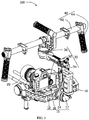
FIG. 1 is a perspective view of a gimbal structure according to an embodiment of the present disclosure. -
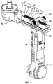
FIG. 2 is a perspective view showing a connection structure of a center of gravity adjusting device and a yaw-axis vertical bar of a support frame of the gimbal structure inFIG. 1 . -
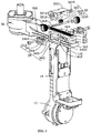
FIG. 3 is an exploded perspective view of the center of gravity adjusting device and the yaw-axis vertical bar of the support frame inFIG. 2 . -
FIG. 4 is a rear view of the center of gravity adjusting device and the yaw-axis vertical bar of the support frame inFIG. 2 . -
FIG. 5 is a top view of a quick release of the center of gravity adjusting device inFIG. 4 . - The present disclosure will be further illustrated in the following detailed description with reference to the drawings.
- Referring to
Figs. 1 to 3 , agimbal structure 100 according to an embodiment of the present disclosure may comprise asupport frame 10 for mounting ashooting device 20, a center of gravity adjusting device 30 and ahandheld frame 40. Thesupport frame 10 and thehandheld frame 40 may be connected to each other through the center of gravity adjusting device 30. The center of gravity of thegimbal structure 100 may be adjusted by the center of gravity adjusting device 30. - In some embodiments, the
support frame 10 may comprise a roll-axis support 12, a yaw-axisvertical bar 14, a yaw-axishorizontal bar 16 and afirst motor 17 rotatably connecting the roll-axis support 12 and the yaw-axisvertical bar 14. The roll-axis support 12 may be provided at a lower side of thegimbal structure 100. Theshooting device 20 may be mounted within the roll-axis support 12. A plane of the roll-axis support 12 may be perpendicular to the yaw-axisvertical bar 14 in an initial state. A shooting angle of theshooting device 20 in the initial state may be an initial viewing angle. A top end of the yaw-axisvertical bar 14 may be provided with two clampingarms 141 with which the center of gravity adjusting device 30 may be connected. Thefirst motor 17 may be mounted at a bottom end of the yaw-axisvertical bar 14 and rotatably connected with the roll-axis support 12. Apower supply device 18 may be provided on the yaw-axisvertical bar 14. Thepower supply device 18 may drive a rotation of a rotating shaft of thefirst motor 17 to rotate the roll-axis support 12 around a central axis of thefirst motor 17. When rotating, an angle of the roll-axis support 12 with respect to the central axis of thefirst motor 17 may vary, such that a shooting angle of theshooting device 20 mounted on the roll-axis support 12 may vary correspondingly. - In some embodiments, the
clamping arms 141 may be formed by extending upward from the top end of the yaw-axisvertical bar 14. The two clampingarms 141 may be spaced apart from each other. Two grooves, for instance afirst groove 1411 and asecond groove 1412, may be provided on an inner surface of eachclamping arm 141 facing theother clamping arm 141. Thefirst groove 1411 andsecond groove 1412 may be spaced apart from each other. Thefirst groove 1411 may be disposed distal to the yaw-axisvertical bar 14, and thesecond groove 1412 may be disposed proximal to the yaw-axisvertical bar 14. - The yaw-axis
horizontal bar 16 may be connected to the yaw-axisvertical bar 14 of thesupport frame 10. In some embodiments, the yaw-axishorizontal bar 16 may be fitted with the clampingarms 141 at the top end of the yaw-axisvertical bar 14. The yaw-axishorizontal bar 16 may comprise anupper surface 161, alower surface 162 and twoside surfaces 163. Theupper surface 161 may be parallel to thelower surface 162, and the twoside surfaces 163 may be respectively connected to edges of theupper surface 161 andlower surface 162. Theupper surface 161 may be provided with arack 164 which is arranged along an extending direction of the yaw-axishorizontal bar 16. A bottom of the yaw-axishorizontal bar 16 may be provided with aboss 165 having a width larger than a distance between the two side surfaces 163. Arecess 166 extending vertically from theupper surface 161 to thelower surface 162 may be provided on each of the twoside surfaces 163 of the yaw-axishorizontal bar 16. A bottom surface of therecess 166 may be aslant surface 167. An angle between theslant surface 167 and theside surface 163 may be an acute angle. In some embodiments, the angle between theslant surface 167 andside surface 163 may be 60°. The yaw-axishorizontal bar 16 may be received between the two clampingarms 141 of the yaw-axisvertical bar 14. Thelower surface 162 of the yaw-axishorizontal bar 16 may be carried on the yaw-axisvertical bar 14. Theboss 165 of the yaw-axishorizontal bar 16 may be received in thesecond grooves 1412 of the two clampingarms 141. A distance between aside surface 163 and a bottom of a correspondingfirst groove 1411 may be D1. - Referring to
FIGs. 3 to 4 , the center of gravity adjusting device 30 may comprise agear adjusting mechanism 32 engagingly connected with the yaw-axishorizontal bar 16, aquick release mechanism 34 for tightening and loosening thegear adjusting mechanism 32, and asecond motor 36 for pivotally connecting the center of gravity adjusting device 30 to thehandheld frame 40. - The
gear adjusting mechanism 32 may be engagingly connected to the yaw-axishorizontal bar 16. Thegear adjusting mechanism 32 may comprise agear fixing member 321, agear 322, agear rotating shaft 323 and adjustingknobs 324. Thegear fixing member 321 may be configured to connect thegear rotating shaft 323 and receive thegear 322, and may be secured to a top end of the clampingarms 141 of the yaw-axisvertical bar 14. Thegear fixing member 321 may comprise ahead 3211 and twoside walls 3212. The twoside walls 3212 may be formed by extending downward from opposing sides of thehead 3211, thus forming anopening 3213 between the twoside walls 3212 for receiving thegear 322. Each of theside walls 3212 may be provided with a steppedhole 3214. The two steppedholes 3214 may be disposed coaxially. Two ends of thegear rotating shaft 323 may be respectively inserted and rotated in the stepped holes 3214. In some embodiments, thegear 322 may be assembled by the following steps. Firstly, one end of thegear rotating shaft 323 may penetrate into theopening 3213 from one of the steppedholes 3214 formed on one of theside walls 3212 of thegear adjusting mechanism 32. Then, thegear 322 may be placed in theopening 3213 and penetrated by the one end of thegear rotating shaft 323. Next, the one end of thegear rotating shaft 323 may penetrate into the other one of the steppedholes 3214 formed on the other one of theside walls 3212. Finally,fasteners 3215 may be provided to fit thegear rotating shaft 323. Thefasteners 3215 may be ratable in the steppedholes 3214 such that thegear rotating shaft 323 may be rotatably connected with thegear fixing member 321. Two ends of thegear rotating shaft 323 may be exposed from the outer peripheral of the twoside walls 3212. In some instances, two adjustingknobs 324 may be provided and respectively mounted to the two ends of thegear rotating shaft 323 which are exposed from the outer peripheral of theside walls 3212. The gearrotating shaft 323 may be rotated by rotating the adjustingknobs 324, such that thegear 322 is rotated. Due to an engagement between therack 164 and thegear 322, the yaw-axishorizontal bar 16 may move back and forth in an extending direction of therack 164 while thegear 322 is rotated. - In some embodiments, the
quick release mechanism 34 may comprise aquick release buckle 341, ascrew 342 connected with thequick release buckle 341, and aslider 343 connected with thescrew 342. - Referring to
FIG. 5 , thequick release buckle 341 may comprise arotating shaft 3411, arotating body 3412 and alug 3413. Therotating body 3412 may be sleeved on an outer peripheral of therotating shaft 3411. Therotating body 3412 may be a cylinder and configured to be eccentric with therotating shaft 3411. For instance, a center of therotating shaft 3411 may not coincide with a center of therotating body 3412. The center of therotating shaft 3411 may deviate from the center of therotating body 3412 by a distance d, such that therotating body 3412 may have a maximum radius R1 and a minimum radius R2, R1>R2. Thelug 3413 may extend outward from a side of therotating body 3412 away from the center of therotating body 3412. In some embodiments, thelug 3413 may be formed in a streamlined shape. An extending direction of thelug 3413 may be substantially perpendicular to a virtual line connecting the center of therotating shaft 3411 and the center of therotating body 3412. For instance, the extending direction of thelug 3413 may be substantially perpendicular to an extending line of the maximum radius R1 of therotating body 3412. Therotating shaft 3411 may be provided with a through-hole 3414 through which the screw 342 (as shown inFIG. 4 ) may penetrate. When thelug 3413 is manipulated, therotating body 3412 may rotate around therotating shaft 3411 such that therotating body 3412 may rotate from the maximum radius to the minimum radius. - Referring again to
FIGs. 3 and4 , theslider 343 may be substantially in a "7" shape and comprise ahorizontal block 3431 and avertical block 3432 which are substantially perpendicular to each other. A width of thehorizontal block 3431 may be D3, which may be smaller than D1 which is the distance between aside surface 163 and the bottom of a correspondingfirst groove 1411, i.e., D3<D1, such that theslider 343 may be movable in a width direction by a certain distance. A height of thehorizontal block 3431 may be D4, which may be less than a height D2 of thefirst groove 1411, i.e., D4<D2, such that theslider 343 may be movable in a height direction by a certain distance. A bottom surface of thevertical block 3432 may be aninclined surface 3433 having the same inclination angle as that of theslant surface 167 of therecess 166 of the yaw-axishorizontal bar 16. Theslider 343 may be displaced in the width and height directions by sliding theinclined surface 3433 in therecess 166 of the yaw-axishorizontal bar 16. Thevertical block 3432 may be provided with a threadedhole 3434 through which thescrew 342 of thequick release mechanism 34 may penetrate and connect theslider 343 with thequick release buckle 341. While assembling thequick release mechanism 34, thevertical block 3432 of theslider 343 may be attached to theside surface 163 of the yaw-axishorizontal bar 16, and thehorizontal block 3431 may be received in thefirst groove 1411 of theclamping arm 141 of the yaw-axisvertical bar 14; then, thescrew 342 of thequick release mechanism 34 may successively penetrate through thequick release buckle 341 and theclamping arm 141 and finally threadedly engage with theslider 343 in order to secure thequick release buckle 341 on one side of theclamping arm 141. A number of gaskets may be provided between thequick release buckle 341 and theclamping arm 141 to facilitate the manipulating of thequick release mechanism 34 and reduce a friction. In some embodiments, acopper gasket 344 and asilicone gasket 345 may be provided between thequick release buckle 341 and theclamping arm 141. The side of thecopper gasket 344 facing therotating body 3412 of thequick release buckle 341 may be a curved surface. - When the
quick release mechanism 34 is operated into a tighten state, thequick release buckle 341 of thequick release mechanism 34 may be manipulated to be placed at one side of theclamping arm 141 of the yaw-axisvertical bar 14. In this state, therotating body 3412 of thequick release buckle 341 may abut against the clampingarm 141 at a portion having the maximum radius, such that theslider 343 is driven by thescrew 342 of thequick release mechanism 34 to abut against acorresponding clamping arm 141. In some embodiments, theslider 343 may slide outward along theslant surface 167 of therecess 166 of the yaw-axishorizontal bar 16 by virtue of a mating of theinclined surface 3433 of theslider 343 with theslant surface 167 of therecess 166, until thevertical block 3432 of theslider 343 abuts against the clampingarm 141 and a top end of thehorizontal block 3431 abuts against an upper wall of thefirst groove 1411 of theclamping arm 141. Under this state, theslider 343 may be locked onto theclamping arm 141 such that the yaw-axishorizontal bar 16 may be fixed with the yaw-axisvertical bar 14. - When the
quick release mechanism 34 is operated into a loosened state, thelug 3413 of thequick release buckle 341 of thequick release mechanism 34 may be manipulated to be substantially perpendicular to theclamping arm 141 of the yaw-axisvertical bar 14. The portion of therotating body 3412 of thequick release buckle 341, which abuts against the clampingarm 141, may shift gradually from the portion having the maximum radius to a portion having the minimum radius, until therotating body 3412 of thequick release buckle 341 abuts against the clampingarm 141 at the portion having the minimum radius thereof, such that theslider 343 may be driven by thescrew 342 of thequick release mechanism 34 to slide inward. In some embodiments, theslider 343 may slide inward along theslant surface 167 of therecess 166 of the yaw-axishorizontal bar 16 by virtue of a mating of theinclined surface 3433 of theslider 343 with theslant surface 167 of the recess 166theslider 343, to loosen thevertical block 3432 of theslider 343 from theslant surface 167 of therecess 166 of the yaw-axishorizontal bar 16 and loosen thehorizontal block 3431 from the upper wall of thefirst groove 1411 of theclamping arm 141. In the loosened state, thehorizontal block 3431 of theslider 343 may not abut against the clampingarm 141, and thevertical block 3432 may not abut against the yaw-axishorizontal bar 16, such that theslider 343 may be released from the clampingarm 141 and the yaw-axishorizontal bar 16. In the loosened state, thegear 322 may engage therack 164 on the yaw-axishorizontal bar 16 by rotating the adjustingknobs 324 of thegear adjusting mechanism 32. By virtue of the engagement, the yaw-axishorizontal bar 16 may slide with respect to the clampingarms 141, such that the center of gravity of theentire gimbal structure 100 may be adjusted. - The other end of the center of gravity adjusting device 30 may be connected to the
second motor 36 through which and thehandheld frame 40 may be rotatably connected with the center of gravity adjusting device 30. In some embodiments, thehandheld frame 40 may comprise ahorizontal rod 42 and a plurality ofhandles 44 mounted on thehorizontal rod 42. In some instances, threehandles 44 may be provided, two of which may be respectively provided at two ends of thehorizontal rod 42, and the remaining one may be provided at a middle portion of thehorizontal rod 42. Thehorizontal rod 42 may be rotatably connected with the center of gravity adjusting device 30 through thesecond motor 36. - The
gimbal structure 100 according to embodiments of the present disclosure may employ aquick release mechanism 34 to adjust the center of gravity adjusting device 30. In some embodiments, the yaw-axishorizontal bar 16 may be locked to or released from the yaw-axisvertical bar 14 of thesupport frame 10 by manipulating thelug 3413 of thequick release mechanism 34. For instance, when the center of gravity of thegimbal structure 100 is to be fixed, the operator may fasten thelug 3413 of thequick release mechanism 34, such that theslider 343 of thequick release mechanism 34 may abut against the clampingarm 141 of the yaw-axisvertical bar 14 and the yaw-axishorizontal bar 16 to prevent a relative moment of the yaw-axishorizontal bar 16 relative to the yaw-axisvertical bar 14. When the center of gravity of thegimbal structure 100 is to be adjusted, the operator may unfastened thelug 3413 of thequick release mechanism 34, such that theslider 343 of thequick release mechanism 34 may slide towards the yaw-axishorizontal bar 16 to release theslider 343 from the clampingarm 141 of the yaw-axisvertical bar 14 and the yaw-axishorizontal bar 16. The yaw-axishorizontal bar 16 may be released from the yaw-axisvertical bar 14 such that they are movable relative to each other. The center of gravity adjusting device 30 may be locked and released by aforementionedquick release mechanism 34 without the aid of additional tools; therefore, the center of gravity adjusting device 30 may timely adjust the center of gravity of thegimbal structure 100. Furthermore, agear adjusting mechanism 32 may be further employed in embodiments of the present disclosure. The yaw-axishorizontal bar 16 may be moved back and forth in the arrangement direction of therack 164 by an engagement between thegear 322 and therack 164. A precise adjustment of the center of gravity of thegimbal structure 100 may be achieved without relying on an operator's experience or intuition. - Embodiments of the present disclosure may further provide a gimbal structure, which may comprise a support frame and a gear adjusting mechanism. The support frame may comprise a roll-axis support, a yaw-axis vertical bar and a yaw-axis horizontal bar carried on the yaw-axis vertical bar. The gear adjusting mechanism may comprise a gear, a gear rotating shaft connecting the gear and adjusting knobs disposed at two ends of the gear rotating shaft. An upper surface of the yaw-axis horizontal bar may be provided with a rack with which the gear may engage. The gear may be rotated by rotating the adjusting knobs to move the yaw-axis horizontal bar relative to the yaw-axis vertical bar.
- In some embodiments, the gear adjusting mechanism may further comprise a gear fixing member which is fixed at a top end of the yaw-axis vertical bar. The gear fixing member may comprise a head and two side walls. An opening may be formed between the two side walls, and the gear may be received in the opening.
- A connecting of the gear adjusting mechanism with other components of the gimbal structure are described in the aforementioned embodiments and drawings.
- It may be appreciated that various modifications and variations may be possible to those having ordinary skill in the art based on the technical concept of the present disclosure, and all these modifications and variations shall fall into the scope of the disclosure as defined by the appended claims.
| Gimbal structure |
| 100 | |
| |
10 |
| Roll- |
12 |
| Yaw-axis |
14 |
| Clamping |
141 |
| |
1411 |
| |
1412 |
| Yaw-axis |
16 |
| |
161 |
| |
162 |
| |
163 |
| |
164 |
| |
165 |
| |
166 |
| |
167 |
| |
17 |
| |
18 |
| |
20 |
| Center of gravity adjusting device | 30 |
| |
32 |
| |
321 |
| |
3211 |
| |
3212 |
| |
3213 |
| Stepped |
3214 |
| Fastener | 3215 |
| |
322 |
| |
323 |
| Adjusting |
324 |
| |
34 |
| |
341 |
| |
3411 |
| |
3412 |
| |
3413 |
| Through- |
3414 |
| |
342 |
| |
343 |
| |
3431 |
| |
3432 |
| Inclined |
3433 |
| Threaded |
3434 |
| |
344 |
| |
345 |
| |
36 |
| |
40 |
| |
42 |
| |
44 |
Claims (17)
- A gimbal structure, said gimbal structure comprising a support frame and a center of gravity adjusting device connected with the support frame,
wherein the support frame comprises a roll-axis support, a yaw-axis vertical bar and a yaw-axis horizontal bar carried on the yaw-axis vertical bar, the center of gravity adjusting device slides the yaw-axis horizontal bar relative to the yaw-axis vertical bar to adjust the center of gravity of the gimbal structure;
wherein the center of gravity adjusting device comprises a quick release mechanism comprising a quick release buckle, a slider and a screw connecting the slider with the quick release buckle; the quick release buckle is mounted on one side of the yaw-axis vertical bar; the slider is mounted between the yaw-axis vertical bar and the yaw-axis horizontal bar; and
wherein the center of gravity adjusting device is locked when the quick release buckle is fastened and the slider is abutted between the yaw-axis vertical bar and the yaw-axis horizontal bar; and the center of gravity adjusting device is adjustable when the quick release buckle is unfastened and the slider is released from the yaw-axis vertical bar and the yaw-axis horizontal bar. - The gimbal structure according to claim 1, wherein the quick release buckle comprises a rotating shaft and a rotating body sleeved on an outer peripheral of the rotating shaft; the rotating body is eccentric such that a center of the rotating body does not coincide with a center of the rotating shaft.
- The gimbal structure according to claim 2, wherein the quick release buckle further comprises a lug; the rotating body has a maximum radius and a minimum radius; the lug extends outward from a side of the rotating body away from the center of the rotating body; with the lug being pulled, the rotating body rotates around the rotating shaft from a portion having the maximum radius to a portion having the minimum radius.
- The gimbal structure according to claim 3, wherein the quick release mechanism further comprises a screw; the screw is inserted into the rotating shaft of the quick release buckle in a direction perpendicular to a side surface of the yaw-axis horizontal bar; the slider is connected to an end of the screw; with the lug being pulled, the screw drives the slider to move inward such that the slider is released from the yaw-axis vertical bar and the yaw-axis horizontal bar.
- The gimbal structure according to claim 1, wherein two clamping arms are provided at a top end of the yaw-axis vertical bar; the yaw-axis horizontal bar is received between the two clamping arms and carried on the top end of the yaw-axis vertical bar.
- The gimbal structure according to claim 5, wherein a first groove and a second groove spaced apart from each other are provided on an inner surface of each clamping arm facing the other clamping arm; a boss is provided at a lower end of the yaw-axis horizontal bar; the slider comprises a horizontal block and a vertical block; the horizontal block is received in the first groove, and the boss is received in the second grooves of the two clamping arms.
- The gimbal structure according to claim 6, wherein a recess is provided on a side surface of the yaw-axis horizontal bar; the vertical block is received in the recess; when the center of gravity adjusting device is locked by the quick release mechanism, the slider is abutted between the recess of the yaw-axis horizontal bar and the clamping arm.
- The gimbal structure according to claim 7, wherein a bottom surface of the recess of the yaw-axis horizontal bar is a slant surface; a bottom surface of the vertical block of the slider is an inclined surface having the same inclination angle as that of the slant surface; when the slider is received in the recess, the inclined surface of the slider is slidable relative to the slant surface of the recess of the yaw-axis horizontal bar, so as to abut the horizontal block of the slider in the first groove of the clamping arm to fix the slider and lock the yaw-axis horizontal bar and the clamping arm.
- The gimbal structure according to claim 1, wherein the gimbal structure further comprises a gear adjusting mechanism which comprising a gear, a gear rotating shaft connected to the gear and adjusting knobs disposed at two ends of the gear rotating shaft; an upper surface of the yaw-axis horizontal bar is provided with a rack with which the gear engages; and the gear is rotated by rotating the adjusting knobs to move the yaw-axis horizontal bar relative to the yaw-axis vertical bar.
- The gimbal structure according to claim 9, wherein the gear adjusting mechanism further comprises a gear fixing member fixed at a top end of the yaw-axis vertical bar; the gear fixing member comprises a head and two side walls; an opening is formed between the two side walls, and the gear is received in the opening.
- The gimbal structure according to claim 1, wherein the support frame is rotatably connected with the center of gravity adjusting device through a first motor, the first motor is mounted at a bottom end of the yaw-axis vertical bar of the support frame.
- The gimbal structure according to claim 11, wherein the gimbal structure further comprises a handheld frame; the handheld frame is rotatably connected with the center of gravity adjusting device through a second motor, the second motor is mounted at the other end of the yaw-axis horizontal bar of the center of gravity adjusting device which is away from the yaw-axis vertical bar.
- The gimbal structure according to claim 12, wherein the handheld frame comprises a horizontal rod and handles mounted on the horizontal rod.
- The gimbal structure according to claim 13, wherein the handheld frame comprises three handles, two of which are mounted respectively at two ends of the horizontal rod, and the remaining one is mounted at a middle portion of the horizontal rod.
- A gimbal structure, said gimbal structure comprising a support frame,
wherein the support frame comprises a roll-axis support, a yaw-axis vertical bar and a yaw-axis horizontal bar carried on the yaw-axis vertical bar; and
wherein the gimbal structure further comprises a gear adjusting mechanism which comprising a gear, a gear rotating shaft connected to the gear and adjusting knobs provided at two ends of the gear rotating shaft; an upper surface of the yaw-axis horizontal bar is provided with a rack with which the gear engages; and the gear is rotated by rotating the adjusting knobs to move the yaw-axis horizontal bar relative to the yaw-axis vertical bar. - The gimbal structure according to claim 15, wherein the gear adjusting mechanism further comprises a gear fixing member provided at a top end of the yaw-axis vertical bar; the gear fixing member comprises a head and two side walls; an opening is formed between the two side walls, and the gear is received in the opening.
- A gear adjusting mechanism, said gear adjusting mechanism comprises a gear, a gear rotating shaft connected to the gear, adjusting knobs provided at two ends of the gear rotating shaft, and a rack engaged with the gear,
wherein the gear adjusting mechanism further comprises a gear fixing member, the gear fixing member comprises a head and two side walls extending from the head; an opening is formed between the two side walls; the gear is received in the opening; the gear rotating shaft is rotatably connected on the two side walls; and the gear is rotated by rotating the adjusting knobs to move the rack.
Priority Applications (1)
| Application Number | Priority Date | Filing Date | Title |
|---|---|---|---|
| EP20194859.3A EP3770480A1 (en) | 2014-06-27 | 2014-06-27 | Tripod head structure and gear adjustment mechanism thereof |
Applications Claiming Priority (1)
| Application Number | Priority Date | Filing Date | Title |
|---|---|---|---|
| PCT/CN2014/081054 WO2015196488A1 (en) | 2014-06-27 | 2014-06-27 | Tripod head structure and gear adjustment mechanism thereof |
Related Child Applications (2)
| Application Number | Title | Priority Date | Filing Date |
|---|---|---|---|
| EP20194859.3A Division EP3770480A1 (en) | 2014-06-27 | 2014-06-27 | Tripod head structure and gear adjustment mechanism thereof |
| EP20194859.3A Division-Into EP3770480A1 (en) | 2014-06-27 | 2014-06-27 | Tripod head structure and gear adjustment mechanism thereof |
Publications (3)
| Publication Number | Publication Date |
|---|---|
| EP3163146A1 true EP3163146A1 (en) | 2017-05-03 |
| EP3163146A4 EP3163146A4 (en) | 2017-10-18 |
| EP3163146B1 EP3163146B1 (en) | 2020-10-21 |
Family
ID=53350106
Family Applications (2)
| Application Number | Title | Priority Date | Filing Date |
|---|---|---|---|
| EP14896139.4A Not-in-force EP3163146B1 (en) | 2014-06-27 | 2014-06-27 | Tripod head structure and gear adjustment mechanism thereof |
| EP20194859.3A Withdrawn EP3770480A1 (en) | 2014-06-27 | 2014-06-27 | Tripod head structure and gear adjustment mechanism thereof |
Family Applications After (1)
| Application Number | Title | Priority Date | Filing Date |
|---|---|---|---|
| EP20194859.3A Withdrawn EP3770480A1 (en) | 2014-06-27 | 2014-06-27 | Tripod head structure and gear adjustment mechanism thereof |
Country Status (5)
| Country | Link |
|---|---|
| US (3) | US10107446B2 (en) |
| EP (2) | EP3163146B1 (en) |
| JP (1) | JP6316989B2 (en) |
| CN (1) | CN104704279B (en) |
| WO (1) | WO2015196488A1 (en) |
Cited By (4)
| Publication number | Priority date | Publication date | Assignee | Title |
|---|---|---|---|---|
| EP3181982A4 (en) * | 2014-08-13 | 2018-04-18 | SZ DJI Osmo Technology Co., Ltd. | Gimbal platform |
| DE102017112111A1 (en) * | 2017-06-01 | 2018-12-06 | Woo-Jun Sung | Device for stabilizing a mobile device |
| US10901384B2 (en) | 2017-03-31 | 2021-01-26 | Daikin Industries, Ltd. | Management apparatus |
| US11792521B1 (en) | 2022-04-27 | 2023-10-17 | Tu Le | Imaging apparatus |
Families Citing this family (33)
| Publication number | Priority date | Publication date | Assignee | Title |
|---|---|---|---|---|
| US9454064B2 (en) | 2014-02-04 | 2016-09-27 | Disney Enterprises, Inc. | Motorized monopod jib for cameras |
| CN104704279B (en) * | 2014-06-27 | 2017-01-18 | 深圳市大疆创新科技有限公司 | Cloud platform structure and its gear adjustment mechanism |
| JP6113365B2 (en) * | 2014-06-30 | 2017-04-12 | エスゼット ディージェイアイ テクノロジー カンパニー リミテッドSz Dji Technology Co.,Ltd | Method and apparatus for adjusting pan head parameter and pan head device |
| EP3862614A1 (en) * | 2014-11-28 | 2021-08-11 | SZ DJI Technology Co., Ltd. | Translation axis assembly and head using same |
| US9798221B2 (en) | 2015-02-20 | 2017-10-24 | Disney Enterprises, Inc. | Motorized monopod jib for cameras |
| WO2017107088A1 (en) * | 2015-12-23 | 2017-06-29 | 深圳市大疆创新科技有限公司 | Support mechanism, adjusting apparatus and pan tilt head for use with same |
| CN107466378B (en) * | 2016-04-14 | 2019-12-10 | 深圳市大疆灵眸科技有限公司 | Vertical stabilization mechanism, pan-tilt device, support device and shooting equipment |
| CN107077155B (en) * | 2016-08-22 | 2019-09-13 | 深圳市大疆灵眸科技有限公司 | Imaging device control method, system and device |
| CN106687376B (en) * | 2016-09-09 | 2020-03-20 | 深圳市大疆创新科技有限公司 | Load assembly and unmanned aerial vehicle mounted with same |
| US10547773B2 (en) | 2016-10-28 | 2020-01-28 | Disney Enterprises, Inc. | User interface aspects for a motorized monopod jib for cameras |
| CN106402590B (en) * | 2016-11-30 | 2018-10-23 | 桂林智神信息技术有限公司 | Adjustable center of gravity fixture |
| CN107223192B (en) * | 2016-12-23 | 2019-01-29 | 深圳市大疆灵眸科技有限公司 | Pan-tilt mounting and dismounting mechanism and photographing device with the same |
| CN107110418B (en) * | 2016-12-28 | 2019-09-10 | 深圳市大疆灵眸科技有限公司 | Holder loads mounting assembly, holder and capture apparatus |
| CN106931284B (en) * | 2017-03-13 | 2023-01-17 | 普宙科技有限公司 | Quick locking device of cloud platform |
| CN113741554A (en) | 2017-04-21 | 2021-12-03 | 深圳市大疆创新科技有限公司 | Cloud deck and cloud deck control method |
| US10583556B2 (en) * | 2017-06-30 | 2020-03-10 | Disney Enterprises, Inc. | Motion stabilization on a motorized monopod jib |
| CN207762487U (en) * | 2017-12-11 | 2018-08-24 | 深圳市道通智能航空技术有限公司 | Camera settings and its holder |
| USD857786S1 (en) * | 2018-01-08 | 2019-08-27 | SZ DJI Technology Co., Ltd. | Gimbal |
| CN108036174A (en) * | 2018-01-12 | 2018-05-15 | 深圳市道通科技股份有限公司 | A kind of holder device |
| ES1211413Y (en) * | 2018-03-22 | 2018-07-20 | Wuntech Factory S L | Slider, motorized handheld slider with handles for photo and video cameras |
| CN108593977B (en) * | 2018-06-11 | 2024-07-30 | 昆山金蚂蚁精密机械有限公司 | Clamping device for test equipment |
| CN111473211B (en) * | 2020-05-26 | 2024-09-06 | 马鞍山职业技术学院 | A loading mechanism for a video surveillance camera |
| JP7542997B2 (en) * | 2020-05-29 | 2024-09-02 | キヤノン株式会社 | Imaging device |
| CN111736230B (en) * | 2020-06-16 | 2023-10-10 | 上海复合材料科技有限公司 | Gravity center adjusting suspension device |
| WO2022000139A1 (en) * | 2020-06-28 | 2022-01-06 | 深圳市大疆创新科技有限公司 | Gimbal device and photographing apparatus |
| CN111824437B (en) * | 2020-07-07 | 2024-08-06 | 哈瓦国际航空技术(深圳)有限公司 | Installation component, quick detach device and unmanned aerial vehicle |
| CN112548897A (en) * | 2020-12-01 | 2021-03-26 | 邵清平 | Positioning mechanism for machining with multidirectional adjustment and high precision |
| CN113460303A (en) * | 2021-07-20 | 2021-10-01 | 温州大学 | Unmanned aerial vehicle for aerial photogrammetry |
| CN113606445A (en) * | 2021-08-10 | 2021-11-05 | 徐州鸿祥机械制造有限公司 | Tripod capable of being quickly contracted, positioned and conveniently opened |
| CN113898828B (en) * | 2021-09-09 | 2023-04-07 | 衡阳亚信企业管理咨询有限公司 | Display device for technical service |
| CN114148538B (en) * | 2021-11-08 | 2023-06-30 | 中航勘察设计研究院有限公司 | Auxiliary tool for aerial photogrammetry |
| CN115183099A (en) * | 2022-07-14 | 2022-10-14 | 江苏联怡通光电科技有限公司 | Liquid crystal screen with double-sided display different effects |
| CN116498838A (en) * | 2022-08-15 | 2023-07-28 | 深圳市海洋王公消照明技术有限公司 | Camera device and method for controlling camera device |
Family Cites Families (24)
| Publication number | Priority date | Publication date | Assignee | Title |
|---|---|---|---|---|
| US5065249A (en) * | 1988-09-26 | 1991-11-12 | Vicon Industries, Inc. | Portable video camera/monitor support |
| US5683063A (en) * | 1996-02-22 | 1997-11-04 | Jlg Industries, Inc. | Elevated camera mount |
| SE514411C2 (en) * | 1999-06-16 | 2001-02-19 | Paul Schuettman | Retaining |
| US6530702B2 (en) * | 2000-12-02 | 2003-03-11 | Thomas H. S. Harris | Operator supported remote camera positioning and control system |
| US6923542B2 (en) * | 2003-03-11 | 2005-08-02 | Thomas H. S. Harris | Operator supported remote camera positioning and control system with longeron based beam |
| US20040223078A1 (en) * | 2003-05-09 | 2004-11-11 | Adam Zadok | Support for hand held video camera |
| US7077582B2 (en) * | 2003-08-20 | 2006-07-18 | Johnson Joseph M | Quick-release clamp for photographic equipment |
| US20060257138A1 (en) * | 2005-05-10 | 2006-11-16 | Fromm Wayne G | Apparatus for supporting a camera |
| JP2007219197A (en) * | 2006-02-17 | 2007-08-30 | M Plan:Kk | Automatic altitude photography device with tripod stand |
| US20070252068A1 (en) * | 2006-04-26 | 2007-11-01 | General Electric Company | Mounting structure |
| DE102006061729A1 (en) * | 2006-12-28 | 2008-07-03 | Robert Bosch Gmbh | Meters Cradle |
| CN101498396B (en) * | 2008-01-30 | 2011-07-27 | 鸿富锦精密工业(深圳)有限公司 | Lifting mechanism |
| CN201804197U (en) * | 2010-05-28 | 2011-04-20 | 冯栓桩 | Adjusting bracket of photographic lens |
| JP2015519612A (en) * | 2012-06-02 | 2015-07-09 | ハリス、トーマス エイチ.エス.HARRIS,Thomas H.S. | Improved camera positioning device |
| US9046743B2 (en) * | 2012-12-06 | 2015-06-02 | Kadir Koymen | Slider support member |
| EP2743559A3 (en) * | 2012-12-12 | 2017-05-10 | Kessler Crane, Inc. | Quick-release plate |
| CN202939404U (en) * | 2012-12-14 | 2013-05-15 | 中山大山摄影器材有限公司 | camera balance stabilizer gimbal |
| CN203258324U (en) * | 2013-04-22 | 2013-10-30 | 杨建军 | Cradle head adjusting mechanism |
| CN203594946U (en) * | 2013-12-05 | 2014-05-14 | 张锦海 | Handheld triaxial shooting pan-tilt device |
| JP6219543B2 (en) * | 2014-06-27 | 2017-10-25 | エスゼット ディージェイアイ オスモ テクノロジー カンパニー リミテッドSZ DJI Osmo Technology Co., Ltd. | Pan head |
| CN104704279B (en) * | 2014-06-27 | 2017-01-18 | 深圳市大疆创新科技有限公司 | Cloud platform structure and its gear adjustment mechanism |
| WO2016000262A1 (en) * | 2014-07-04 | 2016-01-07 | 深圳市大疆创新科技有限公司 | Counterweight assembly, counterweight mechanism using counterweight assembly, and cradle head |
| CN105518370B (en) * | 2014-10-31 | 2018-02-02 | 深圳市大疆灵眸科技有限公司 | The roll axis assembly and the gimbal it uses |
| CN105518757B (en) * | 2015-01-06 | 2018-06-12 | 深圳市大疆灵眸科技有限公司 | Holder remote controler and the hand-held holder using the holder remote controler |
-
2014
- 2014-06-27 CN CN201480002147.2A patent/CN104704279B/en active Active
- 2014-06-27 EP EP14896139.4A patent/EP3163146B1/en not_active Not-in-force
- 2014-06-27 WO PCT/CN2014/081054 patent/WO2015196488A1/en not_active Ceased
- 2014-06-27 EP EP20194859.3A patent/EP3770480A1/en not_active Withdrawn
- 2014-06-27 JP JP2016571718A patent/JP6316989B2/en not_active Expired - Fee Related
-
2016
- 2016-12-27 US US15/390,761 patent/US10107446B2/en active Active
-
2018
- 2018-10-22 US US16/167,447 patent/US10428998B2/en active Active
-
2019
- 2019-09-05 US US16/561,936 patent/US10670180B2/en not_active Expired - Fee Related
Cited By (9)
| Publication number | Priority date | Publication date | Assignee | Title |
|---|---|---|---|---|
| EP3181982A4 (en) * | 2014-08-13 | 2018-04-18 | SZ DJI Osmo Technology Co., Ltd. | Gimbal platform |
| US10073326B2 (en) | 2014-08-13 | 2018-09-11 | Sz Dji Osmo Technology Co., Ltd. | Gimbal |
| US10495949B2 (en) | 2014-08-13 | 2019-12-03 | Sz Dji Osmo Technology Co., Ltd. | Gimbal |
| US10871704B2 (en) | 2014-08-13 | 2020-12-22 | Sz Dji Osmo Technology Co., Ltd. | Gimbal |
| US11422439B2 (en) | 2014-08-13 | 2022-08-23 | Sz Dji Osmo Technology Co., Ltd. | Gimbal |
| US10901384B2 (en) | 2017-03-31 | 2021-01-26 | Daikin Industries, Ltd. | Management apparatus |
| DE102017112111A1 (en) * | 2017-06-01 | 2018-12-06 | Woo-Jun Sung | Device for stabilizing a mobile device |
| DE102017112111B4 (en) | 2017-06-01 | 2021-10-14 | MIRR Motion Tec UG (haftungsbeschränkt) | Device for stabilizing a mobile device |
| US11792521B1 (en) | 2022-04-27 | 2023-10-17 | Tu Le | Imaging apparatus |
Also Published As
| Publication number | Publication date |
|---|---|
| US10107446B2 (en) | 2018-10-23 |
| US10670180B2 (en) | 2020-06-02 |
| CN104704279B (en) | 2017-01-18 |
| US20170108162A1 (en) | 2017-04-20 |
| US10428998B2 (en) | 2019-10-01 |
| EP3770480A1 (en) | 2021-01-27 |
| JP6316989B2 (en) | 2018-04-25 |
| EP3163146B1 (en) | 2020-10-21 |
| US20190056059A1 (en) | 2019-02-21 |
| US20190390818A1 (en) | 2019-12-26 |
| WO2015196488A1 (en) | 2015-12-30 |
| EP3163146A4 (en) | 2017-10-18 |
| CN104704279A (en) | 2015-06-10 |
| JP2017524876A (en) | 2017-08-31 |
Similar Documents
| Publication | Publication Date | Title |
|---|---|---|
| US10670180B2 (en) | Gimbal structure and gear adjusting mechanism thereof | |
| US11969078B1 (en) | Electronic handheld camera supporter | |
| US11131424B2 (en) | Auxiliary mount | |
| JP6090819B2 (en) | Locking device and pan head using the same | |
| US11344107B1 (en) | Electronic handheld camera supporter | |
| JP7097184B2 (en) | Improved display screen fixtures | |
| US9736376B1 (en) | Tilt head, camera stage, multi-post monitor mount and camera stabilizer encompassing the same | |
| CN107110417B (en) | Gimbal Load Mounting Components, Gimbal and Shooting Equipment | |
| US8087629B2 (en) | Stand apparatus | |
| US20110043990A1 (en) | Secondary Computing Device Display System | |
| WO2020211072A9 (en) | Holding mechanism, fastening apparatus and photographing device | |
| CA2983766C (en) | Short throw projector mount with adjustable screw drive | |
| CN204083686U (en) | Cloud platform structure and gear adjustment mechanism thereof | |
| CN203963419U (en) | The The Cloud Terrace of locking device and use thereof | |
| US20150336682A1 (en) | Display mounting apparatus | |
| CN108513604B (en) | Pan-tilt structure and pan-tilt and photographing assembly having the pan-tilt structure | |
| CN104919241B (en) | Mounting system device for positioning electronic equipment | |
| US20090256035A1 (en) | Instrument-mounting head with balance control | |
| US20090263118A1 (en) | Camera-mounting head with balance control | |
| CN209969859U (en) | Support and laser processing equipment | |
| CN205278695U (en) | Supporting mechanism and use adjusting device and cloud platform of this supporting mechanism | |
| CN206514025U (en) | Head load mounting assembly, head and capture apparatus | |
| CN206147237U (en) | With burnt ware mount | |
| CN118687059A (en) | Rotating modules and rotating devices | |
| JP2005095517A (en) | Wall fixture |
Legal Events
| Date | Code | Title | Description |
|---|---|---|---|
| STAA | Information on the status of an ep patent application or granted ep patent |
Free format text: STATUS: THE INTERNATIONAL PUBLICATION HAS BEEN MADE |
|
| PUAI | Public reference made under article 153(3) epc to a published international application that has entered the european phase |
Free format text: ORIGINAL CODE: 0009012 |
|
| STAA | Information on the status of an ep patent application or granted ep patent |
Free format text: STATUS: REQUEST FOR EXAMINATION WAS MADE |
|
| 17P | Request for examination filed |
Effective date: 20170124 |
|
| AK | Designated contracting states |
Kind code of ref document: A1 Designated state(s): AL AT BE BG CH CY CZ DE DK EE ES FI FR GB GR HR HU IE IS IT LI LT LU LV MC MK MT NL NO PL PT RO RS SE SI SK SM TR |
|
| AX | Request for extension of the european patent |
Extension state: BA ME |
|
| RAP1 | Party data changed (applicant data changed or rights of an application transferred) |
Owner name: SZ DJI OSMO TECHNOLOGY CO., LTD. |
|
| DAX | Request for extension of the european patent (deleted) | ||
| A4 | Supplementary search report drawn up and despatched |
Effective date: 20170915 |
|
| RIC1 | Information provided on ipc code assigned before grant |
Ipc: F16M 11/16 20060101ALI20170911BHEP Ipc: F16M 11/20 20060101ALI20170911BHEP Ipc: B64D 47/08 20060101ALI20170911BHEP Ipc: F16M 11/24 20060101ALI20170911BHEP Ipc: G03B 17/56 20060101ALI20170911BHEP Ipc: F16M 11/18 20060101ALI20170911BHEP Ipc: F16M 11/04 20060101AFI20170911BHEP Ipc: F16M 13/04 20060101ALI20170911BHEP |
|
| GRAP | Despatch of communication of intention to grant a patent |
Free format text: ORIGINAL CODE: EPIDOSNIGR1 |
|
| STAA | Information on the status of an ep patent application or granted ep patent |
Free format text: STATUS: GRANT OF PATENT IS INTENDED |
|
| INTG | Intention to grant announced |
Effective date: 20200507 |
|
| GRAS | Grant fee paid |
Free format text: ORIGINAL CODE: EPIDOSNIGR3 |
|
| GRAA | (expected) grant |
Free format text: ORIGINAL CODE: 0009210 |
|
| STAA | Information on the status of an ep patent application or granted ep patent |
Free format text: STATUS: THE PATENT HAS BEEN GRANTED |
|
| AK | Designated contracting states |
Kind code of ref document: B1 Designated state(s): AL AT BE BG CH CY CZ DE DK EE ES FI FR GB GR HR HU IE IS IT LI LT LU LV MC MK MT NL NO PL PT RO RS SE SI SK SM TR |
|
| REG | Reference to a national code |
Ref country code: GB Ref legal event code: FG4D |
|
| REG | Reference to a national code |
Ref country code: CH Ref legal event code: EP |
|
| REG | Reference to a national code |
Ref country code: IE Ref legal event code: FG4D |
|
| REG | Reference to a national code |
Ref country code: DE Ref legal event code: R096 Ref document number: 602014071578 Country of ref document: DE |
|
| REG | Reference to a national code |
Ref country code: AT Ref legal event code: REF Ref document number: 1326180 Country of ref document: AT Kind code of ref document: T Effective date: 20201115 |
|
| REG | Reference to a national code |
Ref country code: NL Ref legal event code: FP |
|
| REG | Reference to a national code |
Ref country code: AT Ref legal event code: MK05 Ref document number: 1326180 Country of ref document: AT Kind code of ref document: T Effective date: 20201021 |
|
| PG25 | Lapsed in a contracting state [announced via postgrant information from national office to epo] |
Ref country code: FI Free format text: LAPSE BECAUSE OF FAILURE TO SUBMIT A TRANSLATION OF THE DESCRIPTION OR TO PAY THE FEE WITHIN THE PRESCRIBED TIME-LIMIT Effective date: 20201021 Ref country code: RS Free format text: LAPSE BECAUSE OF FAILURE TO SUBMIT A TRANSLATION OF THE DESCRIPTION OR TO PAY THE FEE WITHIN THE PRESCRIBED TIME-LIMIT Effective date: 20201021 Ref country code: NO Free format text: LAPSE BECAUSE OF FAILURE TO SUBMIT A TRANSLATION OF THE DESCRIPTION OR TO PAY THE FEE WITHIN THE PRESCRIBED TIME-LIMIT Effective date: 20210121 Ref country code: PT Free format text: LAPSE BECAUSE OF FAILURE TO SUBMIT A TRANSLATION OF THE DESCRIPTION OR TO PAY THE FEE WITHIN THE PRESCRIBED TIME-LIMIT Effective date: 20210222 Ref country code: GR Free format text: LAPSE BECAUSE OF FAILURE TO SUBMIT A TRANSLATION OF THE DESCRIPTION OR TO PAY THE FEE WITHIN THE PRESCRIBED TIME-LIMIT Effective date: 20210122 |
|
| REG | Reference to a national code |
Ref country code: LT Ref legal event code: MG4D |
|
| PG25 | Lapsed in a contracting state [announced via postgrant information from national office to epo] |
Ref country code: LV Free format text: LAPSE BECAUSE OF FAILURE TO SUBMIT A TRANSLATION OF THE DESCRIPTION OR TO PAY THE FEE WITHIN THE PRESCRIBED TIME-LIMIT Effective date: 20201021 Ref country code: IS Free format text: LAPSE BECAUSE OF FAILURE TO SUBMIT A TRANSLATION OF THE DESCRIPTION OR TO PAY THE FEE WITHIN THE PRESCRIBED TIME-LIMIT Effective date: 20210221 Ref country code: PL Free format text: LAPSE BECAUSE OF FAILURE TO SUBMIT A TRANSLATION OF THE DESCRIPTION OR TO PAY THE FEE WITHIN THE PRESCRIBED TIME-LIMIT Effective date: 20201021 Ref country code: SE Free format text: LAPSE BECAUSE OF FAILURE TO SUBMIT A TRANSLATION OF THE DESCRIPTION OR TO PAY THE FEE WITHIN THE PRESCRIBED TIME-LIMIT Effective date: 20201021 Ref country code: BG Free format text: LAPSE BECAUSE OF FAILURE TO SUBMIT A TRANSLATION OF THE DESCRIPTION OR TO PAY THE FEE WITHIN THE PRESCRIBED TIME-LIMIT Effective date: 20210121 Ref country code: AT Free format text: LAPSE BECAUSE OF FAILURE TO SUBMIT A TRANSLATION OF THE DESCRIPTION OR TO PAY THE FEE WITHIN THE PRESCRIBED TIME-LIMIT Effective date: 20201021 Ref country code: ES Free format text: LAPSE BECAUSE OF FAILURE TO SUBMIT A TRANSLATION OF THE DESCRIPTION OR TO PAY THE FEE WITHIN THE PRESCRIBED TIME-LIMIT Effective date: 20201021 |
|
| PG25 | Lapsed in a contracting state [announced via postgrant information from national office to epo] |
Ref country code: HR Free format text: LAPSE BECAUSE OF FAILURE TO SUBMIT A TRANSLATION OF THE DESCRIPTION OR TO PAY THE FEE WITHIN THE PRESCRIBED TIME-LIMIT Effective date: 20201021 |
|
| REG | Reference to a national code |
Ref country code: DE Ref legal event code: R097 Ref document number: 602014071578 Country of ref document: DE |
|
| PG25 | Lapsed in a contracting state [announced via postgrant information from national office to epo] |
Ref country code: LT Free format text: LAPSE BECAUSE OF FAILURE TO SUBMIT A TRANSLATION OF THE DESCRIPTION OR TO PAY THE FEE WITHIN THE PRESCRIBED TIME-LIMIT Effective date: 20201021 Ref country code: RO Free format text: LAPSE BECAUSE OF FAILURE TO SUBMIT A TRANSLATION OF THE DESCRIPTION OR TO PAY THE FEE WITHIN THE PRESCRIBED TIME-LIMIT Effective date: 20201021 Ref country code: SK Free format text: LAPSE BECAUSE OF FAILURE TO SUBMIT A TRANSLATION OF THE DESCRIPTION OR TO PAY THE FEE WITHIN THE PRESCRIBED TIME-LIMIT Effective date: 20201021 Ref country code: CZ Free format text: LAPSE BECAUSE OF FAILURE TO SUBMIT A TRANSLATION OF THE DESCRIPTION OR TO PAY THE FEE WITHIN THE PRESCRIBED TIME-LIMIT Effective date: 20201021 Ref country code: EE Free format text: LAPSE BECAUSE OF FAILURE TO SUBMIT A TRANSLATION OF THE DESCRIPTION OR TO PAY THE FEE WITHIN THE PRESCRIBED TIME-LIMIT Effective date: 20201021 Ref country code: SM Free format text: LAPSE BECAUSE OF FAILURE TO SUBMIT A TRANSLATION OF THE DESCRIPTION OR TO PAY THE FEE WITHIN THE PRESCRIBED TIME-LIMIT Effective date: 20201021 |
|
| PGFP | Annual fee paid to national office [announced via postgrant information from national office to epo] |
Ref country code: FR Payment date: 20210622 Year of fee payment: 8 Ref country code: IT Payment date: 20210625 Year of fee payment: 8 Ref country code: NL Payment date: 20210618 Year of fee payment: 8 |
|
| PLBE | No opposition filed within time limit |
Free format text: ORIGINAL CODE: 0009261 |
|
| STAA | Information on the status of an ep patent application or granted ep patent |
Free format text: STATUS: NO OPPOSITION FILED WITHIN TIME LIMIT |
|
| PG25 | Lapsed in a contracting state [announced via postgrant information from national office to epo] |
Ref country code: DK Free format text: LAPSE BECAUSE OF FAILURE TO SUBMIT A TRANSLATION OF THE DESCRIPTION OR TO PAY THE FEE WITHIN THE PRESCRIBED TIME-LIMIT Effective date: 20201021 |
|
| PGFP | Annual fee paid to national office [announced via postgrant information from national office to epo] |
Ref country code: GB Payment date: 20210625 Year of fee payment: 8 |
|
| 26N | No opposition filed |
Effective date: 20210722 |
|
| PG25 | Lapsed in a contracting state [announced via postgrant information from national office to epo] |
Ref country code: AL Free format text: LAPSE BECAUSE OF FAILURE TO SUBMIT A TRANSLATION OF THE DESCRIPTION OR TO PAY THE FEE WITHIN THE PRESCRIBED TIME-LIMIT Effective date: 20201021 |
|
| PG25 | Lapsed in a contracting state [announced via postgrant information from national office to epo] |
Ref country code: SI Free format text: LAPSE BECAUSE OF FAILURE TO SUBMIT A TRANSLATION OF THE DESCRIPTION OR TO PAY THE FEE WITHIN THE PRESCRIBED TIME-LIMIT Effective date: 20201021 |
|
| PG25 | Lapsed in a contracting state [announced via postgrant information from national office to epo] |
Ref country code: MC Free format text: LAPSE BECAUSE OF FAILURE TO SUBMIT A TRANSLATION OF THE DESCRIPTION OR TO PAY THE FEE WITHIN THE PRESCRIBED TIME-LIMIT Effective date: 20201021 |
|
| REG | Reference to a national code |
Ref country code: CH Ref legal event code: PL |
|
| REG | Reference to a national code |
Ref country code: BE Ref legal event code: MM Effective date: 20210630 |
|
| PG25 | Lapsed in a contracting state [announced via postgrant information from national office to epo] |
Ref country code: LU Free format text: LAPSE BECAUSE OF NON-PAYMENT OF DUE FEES Effective date: 20210627 |
|
| PG25 | Lapsed in a contracting state [announced via postgrant information from national office to epo] |
Ref country code: LI Free format text: LAPSE BECAUSE OF NON-PAYMENT OF DUE FEES Effective date: 20210630 Ref country code: IE Free format text: LAPSE BECAUSE OF NON-PAYMENT OF DUE FEES Effective date: 20210627 Ref country code: CH Free format text: LAPSE BECAUSE OF NON-PAYMENT OF DUE FEES Effective date: 20210630 |
|
| PG25 | Lapsed in a contracting state [announced via postgrant information from national office to epo] |
Ref country code: IS Free format text: LAPSE BECAUSE OF FAILURE TO SUBMIT A TRANSLATION OF THE DESCRIPTION OR TO PAY THE FEE WITHIN THE PRESCRIBED TIME-LIMIT Effective date: 20210221 |
|
| PG25 | Lapsed in a contracting state [announced via postgrant information from national office to epo] |
Ref country code: BE Free format text: LAPSE BECAUSE OF NON-PAYMENT OF DUE FEES Effective date: 20210630 |
|
| PGFP | Annual fee paid to national office [announced via postgrant information from national office to epo] |
Ref country code: DE Payment date: 20220620 Year of fee payment: 9 |
|
| REG | Reference to a national code |
Ref country code: NL Ref legal event code: MM Effective date: 20220701 |
|
| GBPC | Gb: european patent ceased through non-payment of renewal fee |
Effective date: 20220627 |
|
| PG25 | Lapsed in a contracting state [announced via postgrant information from national office to epo] |
Ref country code: NL Free format text: LAPSE BECAUSE OF NON-PAYMENT OF DUE FEES Effective date: 20220701 |
|
| PG25 | Lapsed in a contracting state [announced via postgrant information from national office to epo] |
Ref country code: FR Free format text: LAPSE BECAUSE OF NON-PAYMENT OF DUE FEES Effective date: 20220630 |
|
| PG25 | Lapsed in a contracting state [announced via postgrant information from national office to epo] |
Ref country code: HU Free format text: LAPSE BECAUSE OF FAILURE TO SUBMIT A TRANSLATION OF THE DESCRIPTION OR TO PAY THE FEE WITHIN THE PRESCRIBED TIME-LIMIT; INVALID AB INITIO Effective date: 20140627 Ref country code: GB Free format text: LAPSE BECAUSE OF NON-PAYMENT OF DUE FEES Effective date: 20220627 |
|
| P01 | Opt-out of the competence of the unified patent court (upc) registered |
Effective date: 20230524 |
|
| PG25 | Lapsed in a contracting state [announced via postgrant information from national office to epo] |
Ref country code: CY Free format text: LAPSE BECAUSE OF FAILURE TO SUBMIT A TRANSLATION OF THE DESCRIPTION OR TO PAY THE FEE WITHIN THE PRESCRIBED TIME-LIMIT Effective date: 20201021 |
|
| PG25 | Lapsed in a contracting state [announced via postgrant information from national office to epo] |
Ref country code: IT Free format text: LAPSE BECAUSE OF NON-PAYMENT OF DUE FEES Effective date: 20220627 |
|
| REG | Reference to a national code |
Ref country code: DE Ref legal event code: R119 Ref document number: 602014071578 Country of ref document: DE |
|
| PG25 | Lapsed in a contracting state [announced via postgrant information from national office to epo] |
Ref country code: MK Free format text: LAPSE BECAUSE OF FAILURE TO SUBMIT A TRANSLATION OF THE DESCRIPTION OR TO PAY THE FEE WITHIN THE PRESCRIBED TIME-LIMIT Effective date: 20201021 Ref country code: DE Free format text: LAPSE BECAUSE OF NON-PAYMENT OF DUE FEES Effective date: 20240103 |
|
| PG25 | Lapsed in a contracting state [announced via postgrant information from national office to epo] |
Ref country code: MT Free format text: LAPSE BECAUSE OF FAILURE TO SUBMIT A TRANSLATION OF THE DESCRIPTION OR TO PAY THE FEE WITHIN THE PRESCRIBED TIME-LIMIT Effective date: 20201021 |
|
| PG25 | Lapsed in a contracting state [announced via postgrant information from national office to epo] |
Ref country code: TR Free format text: LAPSE BECAUSE OF FAILURE TO SUBMIT A TRANSLATION OF THE DESCRIPTION OR TO PAY THE FEE WITHIN THE PRESCRIBED TIME-LIMIT Effective date: 20201021 |