EP3162566A1 - Inkjet head and inkjet printer - Google Patents
Inkjet head and inkjet printer Download PDFInfo
- Publication number
- EP3162566A1 EP3162566A1 EP16185968.1A EP16185968A EP3162566A1 EP 3162566 A1 EP3162566 A1 EP 3162566A1 EP 16185968 A EP16185968 A EP 16185968A EP 3162566 A1 EP3162566 A1 EP 3162566A1
- Authority
- EP
- European Patent Office
- Prior art keywords
- ejection
- ejection pulse
- nozzle
- pulse
- pressure chambers
- Prior art date
- Legal status (The legal status is an assumption and is not a legal conclusion. Google has not performed a legal analysis and makes no representation as to the accuracy of the status listed.)
- Withdrawn
Links
Images






Classifications
-
- B—PERFORMING OPERATIONS; TRANSPORTING
- B41—PRINTING; LINING MACHINES; TYPEWRITERS; STAMPS
- B41J—TYPEWRITERS; SELECTIVE PRINTING MECHANISMS, i.e. MECHANISMS PRINTING OTHERWISE THAN FROM A FORME; CORRECTION OF TYPOGRAPHICAL ERRORS
- B41J2/00—Typewriters or selective printing mechanisms characterised by the printing or marking process for which they are designed
- B41J2/005—Typewriters or selective printing mechanisms characterised by the printing or marking process for which they are designed characterised by bringing liquid or particles selectively into contact with a printing material
- B41J2/01—Ink jet
- B41J2/015—Ink jet characterised by the jet generation process
- B41J2/04—Ink jet characterised by the jet generation process generating single droplets or particles on demand
- B41J2/045—Ink jet characterised by the jet generation process generating single droplets or particles on demand by pressure, e.g. electromechanical transducers
- B41J2/04501—Control methods or devices therefor, e.g. driver circuits, control circuits
- B41J2/04543—Block driving
-
- B—PERFORMING OPERATIONS; TRANSPORTING
- B41—PRINTING; LINING MACHINES; TYPEWRITERS; STAMPS
- B41J—TYPEWRITERS; SELECTIVE PRINTING MECHANISMS, i.e. MECHANISMS PRINTING OTHERWISE THAN FROM A FORME; CORRECTION OF TYPOGRAPHICAL ERRORS
- B41J2/00—Typewriters or selective printing mechanisms characterised by the printing or marking process for which they are designed
- B41J2/005—Typewriters or selective printing mechanisms characterised by the printing or marking process for which they are designed characterised by bringing liquid or particles selectively into contact with a printing material
- B41J2/01—Ink jet
- B41J2/135—Nozzles
- B41J2/14—Structure thereof only for on-demand ink jet heads
-
- B—PERFORMING OPERATIONS; TRANSPORTING
- B41—PRINTING; LINING MACHINES; TYPEWRITERS; STAMPS
- B41J—TYPEWRITERS; SELECTIVE PRINTING MECHANISMS, i.e. MECHANISMS PRINTING OTHERWISE THAN FROM A FORME; CORRECTION OF TYPOGRAPHICAL ERRORS
- B41J2/00—Typewriters or selective printing mechanisms characterised by the printing or marking process for which they are designed
- B41J2/005—Typewriters or selective printing mechanisms characterised by the printing or marking process for which they are designed characterised by bringing liquid or particles selectively into contact with a printing material
- B41J2/01—Ink jet
-
- B—PERFORMING OPERATIONS; TRANSPORTING
- B41—PRINTING; LINING MACHINES; TYPEWRITERS; STAMPS
- B41J—TYPEWRITERS; SELECTIVE PRINTING MECHANISMS, i.e. MECHANISMS PRINTING OTHERWISE THAN FROM A FORME; CORRECTION OF TYPOGRAPHICAL ERRORS
- B41J2/00—Typewriters or selective printing mechanisms characterised by the printing or marking process for which they are designed
- B41J2/005—Typewriters or selective printing mechanisms characterised by the printing or marking process for which they are designed characterised by bringing liquid or particles selectively into contact with a printing material
- B41J2/01—Ink jet
- B41J2/015—Ink jet characterised by the jet generation process
- B41J2/04—Ink jet characterised by the jet generation process generating single droplets or particles on demand
- B41J2/045—Ink jet characterised by the jet generation process generating single droplets or particles on demand by pressure, e.g. electromechanical transducers
- B41J2/04501—Control methods or devices therefor, e.g. driver circuits, control circuits
- B41J2/04525—Control methods or devices therefor, e.g. driver circuits, control circuits reducing occurrence of cross talk
-
- B—PERFORMING OPERATIONS; TRANSPORTING
- B41—PRINTING; LINING MACHINES; TYPEWRITERS; STAMPS
- B41J—TYPEWRITERS; SELECTIVE PRINTING MECHANISMS, i.e. MECHANISMS PRINTING OTHERWISE THAN FROM A FORME; CORRECTION OF TYPOGRAPHICAL ERRORS
- B41J2/00—Typewriters or selective printing mechanisms characterised by the printing or marking process for which they are designed
- B41J2/005—Typewriters or selective printing mechanisms characterised by the printing or marking process for which they are designed characterised by bringing liquid or particles selectively into contact with a printing material
- B41J2/01—Ink jet
- B41J2/015—Ink jet characterised by the jet generation process
- B41J2/04—Ink jet characterised by the jet generation process generating single droplets or particles on demand
- B41J2/045—Ink jet characterised by the jet generation process generating single droplets or particles on demand by pressure, e.g. electromechanical transducers
- B41J2/04501—Control methods or devices therefor, e.g. driver circuits, control circuits
- B41J2/04581—Control methods or devices therefor, e.g. driver circuits, control circuits controlling heads based on piezoelectric elements
-
- B—PERFORMING OPERATIONS; TRANSPORTING
- B41—PRINTING; LINING MACHINES; TYPEWRITERS; STAMPS
- B41J—TYPEWRITERS; SELECTIVE PRINTING MECHANISMS, i.e. MECHANISMS PRINTING OTHERWISE THAN FROM A FORME; CORRECTION OF TYPOGRAPHICAL ERRORS
- B41J2/00—Typewriters or selective printing mechanisms characterised by the printing or marking process for which they are designed
- B41J2/005—Typewriters or selective printing mechanisms characterised by the printing or marking process for which they are designed characterised by bringing liquid or particles selectively into contact with a printing material
- B41J2/01—Ink jet
- B41J2/015—Ink jet characterised by the jet generation process
- B41J2/04—Ink jet characterised by the jet generation process generating single droplets or particles on demand
- B41J2/045—Ink jet characterised by the jet generation process generating single droplets or particles on demand by pressure, e.g. electromechanical transducers
- B41J2/04501—Control methods or devices therefor, e.g. driver circuits, control circuits
- B41J2/04588—Control methods or devices therefor, e.g. driver circuits, control circuits using a specific waveform
-
- B—PERFORMING OPERATIONS; TRANSPORTING
- B41—PRINTING; LINING MACHINES; TYPEWRITERS; STAMPS
- B41J—TYPEWRITERS; SELECTIVE PRINTING MECHANISMS, i.e. MECHANISMS PRINTING OTHERWISE THAN FROM A FORME; CORRECTION OF TYPOGRAPHICAL ERRORS
- B41J2/00—Typewriters or selective printing mechanisms characterised by the printing or marking process for which they are designed
- B41J2/005—Typewriters or selective printing mechanisms characterised by the printing or marking process for which they are designed characterised by bringing liquid or particles selectively into contact with a printing material
- B41J2/01—Ink jet
- B41J2/015—Ink jet characterised by the jet generation process
- B41J2/04—Ink jet characterised by the jet generation process generating single droplets or particles on demand
- B41J2/045—Ink jet characterised by the jet generation process generating single droplets or particles on demand by pressure, e.g. electromechanical transducers
- B41J2/04501—Control methods or devices therefor, e.g. driver circuits, control circuits
- B41J2/04596—Non-ejecting pulses
-
- B—PERFORMING OPERATIONS; TRANSPORTING
- B41—PRINTING; LINING MACHINES; TYPEWRITERS; STAMPS
- B41J—TYPEWRITERS; SELECTIVE PRINTING MECHANISMS, i.e. MECHANISMS PRINTING OTHERWISE THAN FROM A FORME; CORRECTION OF TYPOGRAPHICAL ERRORS
- B41J2/00—Typewriters or selective printing mechanisms characterised by the printing or marking process for which they are designed
- B41J2/005—Typewriters or selective printing mechanisms characterised by the printing or marking process for which they are designed characterised by bringing liquid or particles selectively into contact with a printing material
- B41J2/01—Ink jet
- B41J2/135—Nozzles
- B41J2/14—Structure thereof only for on-demand ink jet heads
- B41J2/14201—Structure of print heads with piezoelectric elements
- B41J2/14209—Structure of print heads with piezoelectric elements of finger type, chamber walls consisting integrally of piezoelectric material
-
- B—PERFORMING OPERATIONS; TRANSPORTING
- B41—PRINTING; LINING MACHINES; TYPEWRITERS; STAMPS
- B41J—TYPEWRITERS; SELECTIVE PRINTING MECHANISMS, i.e. MECHANISMS PRINTING OTHERWISE THAN FROM A FORME; CORRECTION OF TYPOGRAPHICAL ERRORS
- B41J2/00—Typewriters or selective printing mechanisms characterised by the printing or marking process for which they are designed
- B41J2/005—Typewriters or selective printing mechanisms characterised by the printing or marking process for which they are designed characterised by bringing liquid or particles selectively into contact with a printing material
- B41J2/01—Ink jet
- B41J2/135—Nozzles
- B41J2/14—Structure thereof only for on-demand ink jet heads
- B41J2002/14475—Structure thereof only for on-demand ink jet heads characterised by nozzle shapes or number of orifices per chamber
-
- B—PERFORMING OPERATIONS; TRANSPORTING
- B41—PRINTING; LINING MACHINES; TYPEWRITERS; STAMPS
- B41J—TYPEWRITERS; SELECTIVE PRINTING MECHANISMS, i.e. MECHANISMS PRINTING OTHERWISE THAN FROM A FORME; CORRECTION OF TYPOGRAPHICAL ERRORS
- B41J2202/00—Embodiments of or processes related to ink-jet or thermal heads
- B41J2202/01—Embodiments of or processes related to ink-jet heads
- B41J2202/10—Finger type piezoelectric elements
-
- B—PERFORMING OPERATIONS; TRANSPORTING
- B41—PRINTING; LINING MACHINES; TYPEWRITERS; STAMPS
- B41J—TYPEWRITERS; SELECTIVE PRINTING MECHANISMS, i.e. MECHANISMS PRINTING OTHERWISE THAN FROM A FORME; CORRECTION OF TYPOGRAPHICAL ERRORS
- B41J2202/00—Embodiments of or processes related to ink-jet or thermal heads
- B41J2202/01—Embodiments of or processes related to ink-jet heads
- B41J2202/12—Embodiments of or processes related to ink-jet heads with ink circulating through the whole print head
Definitions
- Embodiments described herein relate generally to an inkjet head and an inkjet printer, as well as an inkjet printing method.
- An inkjet head of an inkjet printer is equipped with a plurality of ejection areas including a plurality of nozzles.
- a plurality of the ejection areas ejects ink onto a print medium such as a paper at different timing.
- the inkjet head ejects ink from a second ejection area after ejecting the ink from a first ejection area.
- conventional inkjet heads undesirably fail to eject the ink from a next ejection area due to an effect of nozzle negative pressure generated in the initial ejection area.
- an inkjet head comprising:
- the controller respectively divides a plurality of the first pressure chambers and a plurality of the second pressure chambers into a plurality of groups, applies the ejection pulse to one group of the first pressure chambers and applies the non-ejection pulse to one group of the second pressure chambers.
- a plurality of the second driving elements parallel to an arrangement direction of a plurality of the first driving elements is arranged; and the first integrated nozzle and the second integrated nozzle are arranged alternately with respect to the arrangement direction.
- the non-ejection pulse is a rectangular pulse wave; and a width of the non-ejection pulse is equal to or higher than one third of time equivalent to half of a natural vibration period in which the nozzle negative pressure of the first pressure chamber or the second pressure chamber changes.
- the plurality of first integrated nozzles and the plurality of second integrated nozzles are independently arranged in a longitudinal direction of a nozzle plate.
- the inkjet head further comprises:
- the invention also relates to an inkjet printer comprising:
- the invention further concerns an inkjet printing method comprising:
- the ejection pulse comprises an expansion pulse and a contraction pulse.
- the ejection pulse comprises a waveform changing at a plurality of stages or a rectangular waveform.
- the non-ejection pulse comprises a signal having a voltage smaller than a voltage of the signal of the ejection pulse.
- the non-ejection pulse comprises a signal having a width smaller than a width of a signal of the ejection pulse.
- the non-ejection pulse comprises a rectangular pulse wave, and the non-ejection pulse wave is shorter than a rectangular pulse wave of the ejection pulse.
- a timing of the start of the ejection pulse is the same as the start of the non-ejection pulse.
- the inkjet printing method further comprises:
- an inkjet head comprises a plurality of first driving elements, a plurality of second driving elements, a common liquid chamber and a controller.
- a plurality of the first driving elements contains a plurality of first pressure chambers respectively communicating with a plurality of first integrated nozzles containing at least two nozzles.
- a plurality of the second driving elements contains a plurality of second pressure chambers respectively communicating with a plurality of second integrated nozzles containing at least two nozzles.
- the common liquid chamber communicates with a plurality of the first pressure chambers and a plurality of the second pressure chambers.
- the controller applies an ejection pulse to the first driving element and at least one non-ejection pulse to the second driving element before an end timing of the ejection pulse.
- Fig. 1 is a diagram illustrating an example of the configuration of an inkjet printer 100 according to the first embodiment.
- the inkjet printer 100 conveys a paper P as a print medium along a predetermined conveyance route while carrying out various processing such as an image forming processing and the like.
- the inkjet printer 100 is equipped with an inkjet head 10, a housing 110, a paper feed cassette 111 as a paper supply section, a paper discharge tray 112 as a discharge section, a holding roller 113, a conveyance device 114 and a reversing device 118.
- the housing 110 constitutes the contour of the inkjet printer 100.
- the paper feed cassette 111 is arranged inside of the housing 110.
- the paper feed cassette 111 stores the paper P.
- the paper discharge tray 112 is arranged above the housing 110.
- the paper discharge tray 112 discharges the paper P on which an image is formed.
- the holding roller 113 (drum) holds the paper P on the outer surface thereof to rotate.
- the conveyance device 114 conveys the paper P along a predetermined conveyance path A1 formed from the paper feed cassette 111 to the paper discharge tray 112 via the outer circumference of the holding roller 113.
- the reversing device 118 reverses front and rear surfaces of the paper P peeled from the holding roller 113 to supply the reversed paper P to the surface of the holding roller 113 again.
- the conveyance device 114 is equipped with a plurality of guide members and a plurality of rollers for conveyance arranged along the conveyance path A1.
- the rollers for conveyance include a pickup roller, a paper feed roller pair, a resist roller pair, a separation roller pair, a conveyance roller pair and a discharge roller pair. These rollers for conveyance are driven by a motor for conveyance to rotate to send the paper P to the downstream side along the conveyance path A1.
- Sensors S for monitoring conveyance states of the paper are arranged in various places of the conveyance path A1.
- the holding roller 113 rotates in a state of holding the paper P on the surface thereof to convey the paper P.
- a holding device 115 On the outer peripheral part of the holding roller 113, a holding device 115, a head unit 116, a discharge peeling device 117 and a cleaning device 119 are arranged in order from the upstream side to the downstream side.
- the holding device 115 is equipped with a pressing roller 115a and a charging roller 115b.
- the pressing roller 115a presses the outer surface of the holding roller 113.
- the charging roller 115b generates (charges) electrostatic force of a direction in which the paper P is absorbed on the outer surface of the holding roller 113 through supplied electric power.
- the holding roller 113 absorbs the paper P through the electrostatic force.
- the head unit 116 includes a plurality of (four colors) inkjet heads 10 oppositely arranged on the outer surface of the holding roller 113.
- the head unit 116 is equipped with a cyan inkjet head 10C, a magenta inkjet head 10M, a yellow inkjet head 10Y and a black inkjet head 10K.
- the inkjet heads 10C, 10M, 10Y and 10K respectively eject ink from nozzle holes arranged at a predetermined pitch.
- the inkjet heads 10C, 10M, 10Y and 10K discharge the ink to form an image on the paper P held on the outer surface of the holding roller 113.
- the inkjet head 10 (10C, 10M, 10Y and 10K) is described in detail later.
- the discharge peeling device 117 is equipped with a discharge roller 117a for removing the electrostatic force of the paper P and a peeling claw 117b for peeling the paper P from the holding roller 113.
- the cleaning device 119 is equipped with a cleaning member 119a that rotates in a state of contacting with the holding roller 113 to clean the holding roller 113.
- the reversing device 118 reverses the paper P peeled from the holding roller 113 to supply the reversed paper P to the surface of the holding roller 113 again.
- the inkjet printer 100 is further equipped with a controller, a ROM, a RAM and an I/F (interface).
- the controller central control unit
- the ROM is a memory for storing various programs.
- the RAM is a memory for temporarily storing various variable data, image data and the like.
- the I/F (interface) inputs data from an external device or outputs data to the external device.
- the inkjet printer 100 may be further equipped with proper elements which are necessary or delete unnecessary elements.
- the inkjet head 10 receives the supply of the ink (print member) from the inkjet printer 100 to form an image on the paper P as the print medium.
- the print member may be various kinds of ink for forming images. Further, the print member may be functional ink including various functions used except the use of forming an image.
- the inkjet head 10 is connected with a tank (ink tank or liquid tank) loaded in the inkjet printer 100 via a tube.
- the inkjet head 10 receives the supply of the ink from the tank via the tube.
- the inkjet head 10 is equipped with a head main body 12, a unit section 13 and a control circuit 14 (controller or control section).
- the head main body 12 is formed on the unit section 13.
- the control circuit 14, which is arranged on the side surface of the unit section 13, sends a control signal to the head main body 12.
- the unit section 13 includes a manifold for forming a part of a route between the head main body 12 and the tank and a member for connecting with the inkjet printer 100.
- the control circuit 14 includes a substrate main body 15 and a pair of film carrier packages (FCP) 16.
- the substrate main body 15 is a rectangular printed wiring board.
- Various electronic components and connectors are mounted in the substrate main body 15.
- a pair of the FCPs 16 is mounted in the substrate main body 15.
- Each of the pair of the FCPs 16 on which a plurality of wirings is formed includes a film made of resin having softness and an IC 17 connected with a plurality of the wirings.
- the film is tape automated bonding (TAB).
- TAB tape automated bonding
- the pair of the FCPs 16 is mounted from the substrate main body 15 along the side surface of the unit section 13 and connected with the head main body 12.
- the IC 17 is a member for applying a voltage to an electrode 34.
- the IC 17 is fixed on the film through the resin.
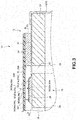
- Fig. 3 is a cross-sectional view of the inkjet head taken along a F3-F3 line according to the first embodiment.
- an end part of the FCP 16 is connected with a wiring pattern 21 on a base plate 22 by thermocompression bonding through an anisotropic conductive film (ACF).
- ACF anisotropic conductive film
- the head main body 12 ejects a liquid drop (ink drop) onto the print medium (paper P).
- the head main body 12 is equipped with the base plate 22, a nozzle plate 23, a frame member 24 and a block 25 in which a plurality of driving elements 31 is formed.
- the base plate 22 is formed into a rectangular plate shape.
- the base plate 22 is made from, for example, ceramic like alumina.
- the supply holes 26 can be parallelly arranged substantially at the center of the base plate 22 in a longitudinal direction of the base plate 22.
- the supply hole 26 communicates with an ink supply section 28 of the manifold of the unit section 13.
- the supply hole 26 is connected with the tank via the ink supply section 28.
- the discharge holes 27 are parallelly arranged at two sides of the base plate 22 across the supply hole 26 in the longitudinal direction of the base plate 22.
- the discharge hole 27 communicates with an ink discharge section 29 of the manifold of the unit section 13.
- the discharge hole 27 is connected with the tank via the ink discharge section 29.
- the frame member 24 can be a square frame-shaped member.
- the frame member 24 is made from, for example, nickel alloy.
- the frame member 24 intermediates between the base plate 22 and the nozzle plate 23.
- the frame member 24 is respectively bonded with a mounting surface and the nozzle plate 23.
- the driving element 31 is formed by two piezoelectric bodies.
- the driving element 31 includes two plate-like piezoelectric bodies formed by, for example, lead zirconate titanate (PZT).
- PZT lead zirconate titanate
- the two piezoelectric bodies are bonded with each other in such a manner that their directions of polarization are opposite to each other in the thickness direction.
- the block 25 in which a plurality of the driving elements 31 is formed is bonded on the mounting surface of the base plate 22. As shown in Fig. 3 , the block 25 is formed into a trapezoid. The top of the driving element 31 is bonded with the nozzle plate 23.
- the block 25 includes a plurality of grooves.
- the grooves respectively extend in a direction crossing with the longitudinal direction of the block 25 (longitudinal direction of the inkjet head 10).
- the plate-like driving elements 31 are separated by the grooves.
- Fig. 5 is a cross-sectional view of the inkjet head 10 taken along a F5-F5 line.
- the electrode 34 is arranged on both surfaces of the driving element 31.
- the electrode 34 covers the bottom of the groove (pressure chamber 32) and side surfaces of the driving element 31.
- the electrode 34 is formed by, for example, carrying out laser patterning on nickel thin film.
- the electrode 34 is electrically connected with the IC 17.
- a plurality of the wiring patterns 21 extending in a direction crossing with the longitudinal direction of the base plate 22 from a plurality of the driving elements 31 is arranged on the mounting surface of the base plate 22.
- the wiring pattern 21 is formed by, for example, carrying out the laser patterning on the nickel thin film formed on the base plate 22.
- the nozzle plate 23 is formed with, for example, polyimide film, and is substantially rectangular.
- the nozzle plate 23 faces the base plate 22.
- the nozzle plate 23 includes a first surface 23A (pressure chamber surface) at a pressure chamber 32 side and a second surface 23B (outer surface) opposite to the first surface 23A.
- the nozzle plate 23 includes an integrated nozzle 35.
- the integrated nozzle 35 penetrates the nozzle plate 23.
- the integrated nozzle 35 is composed of a first integrated nozzle 35a and a second integrated nozzle 35b.
- the first integrated nozzle 35a and the second integrated nozzle 35b are respectively composed of at least two nozzles.
- the first integrated nozzle 35a is composed of at least two of the nozzles formed in the nozzle plate 23.
- the second integrated nozzle 35b is composed of at least two of the other nozzles formed in the nozzle plate 23.
- the number of the nozzles constituting the integrated nozzle 35 is not specifically limited.
- the first integrated nozzle 35a and the second integrated nozzle 35b are respectively composed of two nozzles arranged in parallel in a lateral direction of the nozzle plate 23.
- the nozzle plate 23 includes a plurality of the first integrated nozzles 35a and a plurality of the second integrated nozzles 35b.
- a plurality of the first integrated nozzles 35a and a plurality of the second integrated nozzles 35b are respectively arranged in parallel along the longitudinal direction of the nozzle plate 23.
- An area inside the groove arranged in the block 25 is the pressure chamber 32 facing a first nozzle 36 and a second nozzle 37 described later.
- a driving element 31 enables the liquid drops to be simultaneously ejected from the first nozzle 36 and the second nozzle 37 described later.
- a common liquid chamber 33 supplies the liquid (ink) to each pressure chamber 32.
- the common liquid chamber 33 is composed of the nozzle plate 23, a part of the base plate 22 in the vicinity of the supply hole 26 and the inclined plane portion of the block 25.
- the common liquid chamber 33 communicates with each pressure chamber 32.
- each integrated nozzle 35 includes the first nozzle 36 and the second nozzle 37.
- the second nozzle 37 is arranged in the vicinity of the first nozzle 36 adjacent to the first nozzle 36 in the lateral direction of the nozzle plate 23.
- the first nozzle 36 and the second nozzle 37 face the same pressure chamber 32.
- the inkjet head 10 is equipped with two rows (a plurality of rows) of driving elements 31 including one row of plural driving elements 31a and one row of plural driving elements 31b, arranged in one direction, which are parallel to each other.
- the inkjet head 10 is equipped with the driving elements 31a as the row at the left side and the driving elements 31b as the row at the right side.
- the longitudinal direction of the driving element 31 has an orthogonal relation to an arrangement direction of the driving element; however, the longitudinal direction of the driving elements 31 may have a predetermined angle to the arrangement direction.
- the plural nozzles of the integrated nozzle 35 are arranged in a direction parallel to the longitudinal direction of the driving elements.
- the ejection area 51a is a first ejection area
- the ejection area 51b is a second ejection area.
- the ejection area 51a and the ejection area 51b are arranged at a predetermined interval.
- the ejection area 51a includes a plurality of the driving elements 31a, the electrodes 34a and the first integrated nozzles 35a.
- the ejection area 51b includes a plurality of the driving elements 31b, the electrodes 34b and the second integrated nozzles 35b.
- the pressure chamber 32 (32a or 32b) is formed between the driving elements 31 (31a or 31b).
- the pressure chamber 32 is formed by two driving elements 31 and the electrodes 34 (34a or 34b) arranged on two surfaces of the driving element 31.
- the integrated nozzle 35 for ejecting the ink is arranged substantially at the center of the longitudinal direction of the pressure chamber 32 on the nozzle plate 23.
- the longitudinal direction of the pressure chamber 32 is orthogonal to the arrangement direction of the driving element 31.
- the common liquid chamber 33 is arranged between the ejection area 51a and the ejection area 51b.
- the discharge hole 27 at one end side of the ejection area 51a and the supply hole 26 at the other end side thereof are arranged on the base plate 22.
- the supply hole 26 at one end side of the ejection area 51b and the discharge hole 27 at the other end side thereof are arranged on the base plate 22.
- a plurality of the supply holes 26 is arranged in the arrangement direction of the driving element 31.
- a plurality of rows of the plural discharge holes 27 is arranged in the arrangement direction of the driving element 31.
- the discharge hole 27 is arranged in the vicinity of the frame member 24.
- the first integrated nozzle 35a communicates with the pressure chamber 32a (first pressure chamber) formed by the driving elements 31a (first driving elements) and the electrodes 34a arranged on the both surfaces of the driving element 31a. Further, the second integrated nozzle 35b communicates with the pressure chamber 32b (second pressure chamber) formed by the driving elements 31b (second driving elements) and the electrodes 34b arranged on the both surfaces of the driving element 31b.
- the first integrated nozzle 35a in the ejection area 51a and the second integrated nozzle 35b in the ejection area 51b are not arranged collinearly with respect to a direction orthogonal to the arrangement direction of the driving element 31.
- the first integrated nozzle 35a in the ejection area 51a and the second integrated nozzle 35b in the ejection area 51b are arranged at positions different from each other with respect to the arrangement direction of the driving element 31.
- the first integrated nozzle 35a and the second integrated nozzle 35b are described.
- the configuration of the first integrated nozzle 35a is described.
- the configuration of the second integrated nozzle 35b is the same as that of the first integrated nozzle 35a, the description thereof is omitted.
- Fig. 6 is a diagram illustrating an example of a first surface 23A of the nozzle plate 23.
- Fig. 7 is a cross-sectional view illustrating of the nozzle plate 23 taken along a F7-F7 line.
- Fig. 8 is a diagram illustrating an example of a second surface 23B of the nozzle plate 23.
- the first integrated nozzle 35a is equipped with a first nozzle 36a and a second nozzle 37a.
- the first nozzle 36a and the second nozzle 37a have the same shape.
- the first nozzle 36a and the second nozzle 37a are formed into, for example, a trapezoid the diameter of which becomes small with approaching the second surface 23B.
- the first integrated nozzle 35a penetrates the first surface 23A and the second surface 23B.
- the first nozzle 36a includes a first opening 36Aa arranged on the first surface 23A and a second opening 36Ba arranged on the second surface 23B.
- the second nozzle 37a includes a third opening 37Aa arranged on the first surface 23A and a fourth opening 37Ba arranged on the second surface 23B.
- a first peripheral surface 36Ca (inner peripheral surface, side surface and inclined surface) of the first nozzle 36a linearly extends from the second surface 23B towards the first surface 23A.
- the first peripheral surface 36Ca (inner peripheral surface, side surface and inclined surface) of the first nozzle 36a crosses with a second peripheral surface 37Ca (inner peripheral surface, side surface and inclined surface) of the second nozzle 37a linearly extending from the second surface 23B towards the first surface 23A en route from the second surface 23B to the first surface 23A.
- a part of the first opening 36Aa is overlapped with a part of the third opening 37Aa.
- the first opening 36Aa and the third opening 37Aa are consecutively arranged.
- a part of the first nozzle 36a at the first surface 23A side communicates with a part of the second nozzle 37a at the first surface 23A side to be integrated.
- the second opening 36Ba is separated from the fourth opening 37Ba but arranged in the vicinity of the fourth opening 37Ba.
- a part of the first nozzle 36a at the second surface 23B side is separated from a part of the second nozzle 37a at the second surface 23B side.
- the second integrated nozzle 35b is equipped with a third nozzle 36b and a fourth nozzle 37b.
- the third nozzle 36b is equipped with a fifth opening 36Ab and a sixth opening 36Bb.
- the fourth nozzle 37b is equipped with a seventh opening 37Ab and an eighth opening 37Bb.
- the third nozzle 36b, the fourth nozzle 37b, the fifth opening 36Ab, the sixth opening 36Bb, the seventh opening 37Ab and the eighth opening 37Bb are respectively the same as the first nozzle 36a, the second nozzle 37a, the first opening 36Aa, the second opening 36Ba, the third opening 37Aa and the fourth opening 37Ba, and thus, the description thereof is omitted.
- first nozzle 36a and the second nozzle 37a may be independent of each other without communicating with each other. In other words, the first nozzle 36a and the second nozzle 37a do not communicate with each other at the first surface 23A side, at the second surface 23B side and between the two surfaces.
- the third nozzle 36b and the fourth nozzle 37b may be independent of each other without communicating with each other. In other words, the third nozzle 36b and the fourth nozzle 37b do not communicate with each other at the first surface 23A side, at the second surface 23B side and between the two surfaces.
- partition may be arranged between each pressure chamber 32 in the ejection area 51a and each pressure chamber 32 in the ejection area 51b.
- the inkjet head 10 is equipped with the supply holes respectively at the ejection area 51a side and at the ejection area 51b side.
- the two supply holes communicate with the same common ink chamber.
- the common ink chamber may be formed at back surface side (in other words, outer surface side of the base plate 22) of the pressure chamber 32.
- the shape and position of the common ink chamber are not limited to a specific configuration.
- the inkjet head 10 is a liquid (ink) circulation type inkjet head 10.
- the ink ejected from the tank is supplied to the pressure chamber 32 (32a and 32b) via the supply hole 26 and the common liquid chamber 33.
- the ink which is not ejected in the pressure chamber 32 is collected from the discharge hole 27 to the tank. In this way, in the inkjet head 10, the ink is circulated between the tank and the inside of the inkjet head 10.
- the ejection operations of the first integrated nozzle 35a and the second integrated nozzle 35b are identical, and thus, only the ejection operations of the first integrated nozzle 35a are described hereinafter and the ejection operations of the second integrated nozzle 35b are omitted.
- Fig. 9 is a cross-sectional view of the pressure chamber 32a along the thickness direction of the nozzle plate 23.
- the control circuit 14 drives the driving element 31a to increase or decrease the volume of the pressure chamber 32a in order to enable the ink to be ejected from the first integrated nozzle 35a.
- the control circuit 14 applies a voltage to the electrode 34a to drive the driving element 31a to increase or decrease the volume of the pressure chamber 32a.
- Fig. 10 is a diagram illustrating a state in which the control circuit 14 drives the driving element 31a so as to increase the volume of the pressure chamber 32a.
- the control circuit 14 applies a pulse (expansion pulse) which expands the volume of the pressure chamber 32a to the driving element 31a. If the control circuit 14 applies the expansion pulse to the driving element 31a, as shown in Fig. 10 , the driving element 31a deforms towards the outer side of the pressure chamber 32a. As a result, the volume of the pressure chamber 32a is increased compared with the initial state (state in Fig. 9 ).
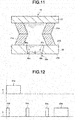
- Fig. 11 is a diagram illustrating a state in which the control circuit 14 drives the driving element 31a so as to decrease the volume of the pressure chamber 32a.
- the control circuit 14 applies a pulse (contraction pulse) which contracts the volume of the pressure chamber 32a to the driving element 31a. If the control circuit 14 applies the contraction pulse to the driving element 31a, as shown in Fig. 11 , the driving element 31a deforms towards the inside of the pressure chamber 32a. As a result, the volume of the pressure chamber 32a is decreased compared with the initial state (state in Fig. 9 ).
- the control circuit 14 After the control circuit 14 temporarily increases the volume of the pressure chamber 32a, if the volume of the pressure chamber 32a is smaller than the original volume, the liquid in the pressure chamber 32a is pressurized, and the ink from the first nozzle 36a and the second nozzle 37a is simultaneously ejected.
- the control circuit 14 applies an ejection pulse composed of the expansion pulse and the contraction pulse to the electrode 34 of the driving element 31a to enable the ink to be ejected.
- the waveform of the ejection pulse may be, for example, a waveform changing at a plurality of stages or a rectangular waveform.
- the configuration of the ejection pulse is not limited to the specific configuration.
- meniscus surfaces 43a of the first nozzle 36a and the second nozzle 37a protrude towards the external.
- the ejected ink is ejected as the liquid drop towards the print medium.
- the meniscus surface 43a of the first nozzle 36a and the meniscus surface 43a of the second nozzle 37a retreat towards the inside of the first nozzle 36a and the second nozzle 37a.
- the control circuit 14 sets the ejection area 51a and the ejection area 51b.
- the ejection area 51a includes one row of the first integrated nozzles 35a (e.g., a row at the left side of Fig. 5 ) which are arranged in the longitudinal direction of the nozzle plate 23.
- the ejection area 51b includes a row of the second integrated nozzles 35b (e.g., a row at the right side of Fig. 5 ) arranged in the longitudinal direction of the nozzle plate 23.
- the control circuit 14 enables the ink to be ejected from the integrated nozzle 35 in each ejection area. For example, at the time the print medium passes from the ejection area 51a side, the control circuit 14 enables the ink to be ejected from the ejection area 51a, and sequentially enables the ink to be ejected from the ejection area 51b.
- control circuit 14 sets a channel No for each pressure chamber 32 (channel) in the predetermined ejection areas 51a and 51b. For example, the control circuit 14 sets the channel No of each pressure chamber 32 in order from one end of the nozzle plate 23.
- the pressure chamber 32 shares the driving element 31 with the respectively adjacent pressure chambers 32.
- the control circuit 14 cannot drive each pressure chamber 32 at the same time. Consequently, the control circuit 14 divides the pressure chambers 32 into a plurality of groups every n+1 (n is an integer equal to or greater than 2) channels to drive each group (division).
- the control circuit 14 divides the pressure chambers 32 into three groups every three channels to carry out division driving, in other words, a case of three division driving is exemplified.
- the control circuit 14 divides the pressure chambers 32 into No. 3n-2 channel group (first division), No. 3n-1 channel group (second division) and No. 3n channel group (third division) (n is an integer equal to or greater than 1). For example, the control circuit 14 enables the ink to be ejected in the order of the first division, the second division and the third division.
- control circuit 14 may adopt a method (Multi-drop drive) for enabling the ink to be continuously ejected from one channel for many times. For example, the control circuit 14 controls the times that the ink is continuously ejected in response to print data.
- Multi-drop drive Multi-drop drive
- Fig. 12 is a timing chart illustrating an example of the pulse applied to the channel by the control circuit 14.
- the control circuit 14 enables the ink to be ejected from a predetermined division of the ejection area 51b after enabling the ink to be ejected from a predetermined division of the ejection area 51a.
- a waveform a exemplifies a pulse applied to a predetermined division (division a) of the ejection area 51a.
- a waveform b exemplifies a pulse applied to a division (division b) of the ejection area 51b corresponding to the predetermined division of the ejection area 51a.
- the control circuit 14 applies an ejection pulse 61a to the division a at a predetermined timing. Further, the control circuit 14 sequentially applies non-ejection pulses 62b to 64b to the division b and then applies the ejection pulse 61b thereto.
- the non-ejection pulse is a signal which does not lead to the ejection of the ink.
- the non-ejection pulse is a signal which enables the pressure chamber 32 to generate vibration but does not lead to the ejection of the ink.
- the non-ejection pulse is a signal of which a voltage is smaller than that of the ejection pulse.
- the non-ejection pulse is a signal of which a width is smaller than that of the ejection pulse.
- the non-ejection pulse is a rectangular pulse wave.
- the waveform of the non-ejection pulse is not limited to the specific configuration. In the present embodiment, the non-ejection pulse is set to the rectangular pulse wave. Furthermore, the non-ejection pulse is set to a pulse wave shorter than the ejection pulse.
- the control circuit 14 applies at least one non-ejection pulse to the division b until the application of the ejection pulse to the division a is ended. In other words, the control circuit 14 applies a non-ejection pulse to the division b of which the application is ended until an end timing at which the application of the ejection pulse to the division a is ended.
- the control circuit 14 starts to apply the non-ejection pulse 62b to the division b at a timing when the application of the ejection pulse 61a to the division a is started.
- the control circuit 14 makes the timing of the start of the ejection pulse 61a of the division a consistent with the timing of the start of the non-ejection pulse 62b of the division b.
- the control circuit 14 After applying the non-ejection pulse 62b to the division b, the control circuit 14 applies the non-ejection pulse 63b to the division b at a predetermined interval. After applying the non-ejection pulse 63b to the division b, the control circuit 14 applies the non-ejection pulse 64b to the division b at a predetermined interval. After applying the non-ejection pulse 64b to the division b, the control circuit 14 applies the ejection pulse 61b to the division b at a predetermined interval.
- the interval between the non-ejection pulse 62b and the non-ejection pulse 63b may be identical to or different from that between the non-ejection pulse 63b and the non-ejection pulse 64b.
- the control circuit 14 may apply three or more non-ejection pulses or only one non-ejection pulse between the non-ejection pulse 62b and the ejection pulse 61b. Further, the control circuit 14 may not apply a non-ejection pulse between the non-ejection pulse 62b and the ejection pulse 61b. Further, the control circuit 14 may apply a non-ejection pulse prior to the non-ejection pulse 62b.
- Fig. 13 is a timing chart illustrating another example of the pulse applied to the channel by the control circuit 14.
- the control circuit 14 enables the ink to be ejected from the predetermined division of the ejection area 51b after enabling the ink to be ejected from the predetermined division of the ejection area 51a.
- the control circuit 14 applies an ejection pulse 71a to the division a at a predetermined timing. Further, the control circuit 14 sequentially applies non-ejection pulses 72b to 74b to the division b, and then applies an ejection pulse 71b thereto.
- the control circuit 14 applies the non-ejection pulse 72b to the division b at a predetermined timing before applying the ejection pulse 71a to the division a. If the non-ejection pulse 72b is applied to the division b, the control circuit 14 applies the non-ejection pulse 73b of which the application is ended at the same timing as the end of the application of the ejection pulse 71a to the division a. In other words, the control circuit 14 makes the timing of the falling of the ejection pulse 71a of the division a consistent with the timing of the falling of the non-ejection pulse 73b.
- the control circuit 14 applies a non-ejection pulse 74b to the division b at a predetermined interval. If a non-ejection pulse 74b is applied to the division b, the control circuit 14 applies the ejection pulse 71b to the division b at a predetermined interval.
- the interval between the non-ejection pulse 72b and the non-ejection pulse 73b may be identical to or different from that between the non-ejection pulse 73b and the non-ejection pulse 74b.
- the control circuit 14 may apply two or more non-ejection pulses or may not apply any non-ejection pulse between the non-ejection pulse 73b and the ejection pulse 71b.
- the control circuit 14 may apply two or more non-ejection pulses or may not apply any non-ejection pulse before the non-ejection pulse 73b. Further, the control circuit 14 may apply a plurality of non-ejection pulses to the division b while an ejection pulse is applied to the division a.
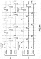
- Fig. 14 is a timing chart for describing a concrete example of the pulses applied to each division of the ejection area 51a and each division of the ejection area 51b by the control circuit 14.
- Fig. 14 illustrates an example (example shown in Fig. 13 ) in which a timing at which the ejection pulse is ended is consistent with a timing at which the non-ejection pulse is ended.
- control circuit 14 enables the ink to be ejected from each division of the ejection area 51a, and next enables the ink to be ejected from each division of the ejection area 51a and each division of the ejection area 51b.
- the control circuit 14 enables the ink to be ejected from the first division, the second division and the third division in order.
- a waveform a1 illustrates an example of a pulse applied to the first division of the ejection area 51a.
- a waveform a2 illustrates an example of a pulse applied to the second division of the ejection area 51a.
- a waveform a3 illustrates an example of a pulse applied to the third division of the ejection area 51a.
- a waveform b1 illustrates an example of a pulse applied to the first division of the ejection area 51b.
- a waveform b2 illustrates an example of a pulse applied to the second division of the ejection area 51b.
- a waveform b3 illustrates an example of a pulse applied to the third division of the ejection area 51b.
- the control circuit 14 applies an ejection pulse to the first division of the ejection area 51a. Further, the control circuit 14 applies a non-ejection pulse to the first division of the ejection area 51b of which the application is ended at the same timing as the end of the application of the ejection pulse.
- the control circuit 14 applies an ejection pulse to the second division of the ejection area 51a. Further, the control circuit 14 applies a non-ejection pulse to the second division of the ejection area 51b of which the application is ended at the same timing as the end of the application of the ejection pulse.
- the control circuit 14 applies an ejection pulse to the third division of the ejection area 51a. Further, the control circuit 14 applies a non-ejection pulse to the third division of the ejection area 51b of which the application is ended at the same timing as the end of the application of the ejection pulse.
- control circuit 14 applies the ejection pulses to the first division, the second division and the third division of the ejection area 51a. Further, similarly, the control circuit 14 applies the non-ejection pulse to the first division, the second division and the third division of the ejection area 51b.
- the control circuit 14 simultaneously applies the ejection pulse to the first division of the ejection area 51b and the ejection pulse to the first division of the ejection area 51a at a predetermined timing. For example, the control circuit 14 applies the ejection pulses to the first divisions of both ejection areas at a timing when the paper P is conveyed to a position where the ejection area 51b ejects the ink. If the ejection pulses are applied to the first divisions of both ejection areas, the control circuit 14 applies the ejection pulses to the second divisions of both ejection areas. If the ejection pulses are applied to the second divisions of both ejection areas, the control circuit 14 applies the ejection pulses to the third divisions of both ejection areas.
- control circuit 14 may not apply the ejection pulse to a predetermined division of the ejection area 51a at a predetermined timing.
- control circuit 14 may apply a non-ejection pulse to the predetermined division of the ejection area 51a before an end timing of the ejection pulse applied to a predetermined division of the ejection area 51b.
- control circuit 14 may apply the non-ejection pulse to an empty part of the ejection pulse (in other words, at the timing of applying the ejection pulse in a case of ejecting the maximum ejection number). Further, the control circuit 14 may apply the non-ejection pulse to a part of the empty part.
- the inkjet head 10 is equipped with the ejection areas 51a and 51b.
- the inkjet head 10 ejects the ink ahead from either of the ejection areas 51a and 51b. If the inkjet head 10 ejects the ink from an initial ejection area (for example, the ejection area 51a), pressure (nozzle negative pressure) of the pressure chamber 32 of the ejection area, the common liquid chamber 33 communicating with the pressure chamber and the pressure chamber 32 of the other ejection area (for example, the ejection area 51b) communicating with the common liquid chamber 33 is reduced.
- the inkjet head 10 In a case of ejecting the ink from the ejection area 51b after ejecting the ink from the ejection area 51a, the inkjet head 10 ejects the ink from the ejection area 51b in most cases in a state in which the nozzle negative pressure is lower than that before the ejection of the ink. If the inkjet head 10 ejects the ink in a state in which the nozzle negative pressure is lower, the first ejection failure (for example, blurring or decrease in an ejection volume) occurs in most cases. In other words, the inkjet head 10 is easy to generate the first ejection failure if the nozzle negative pressure before the ejection of the ink is low.
- the first ejection failure for example, blurring or decrease in an ejection volume
- the second ejection failure (e.g., blurring) occurs in most cases. If the nozzle negative pressure is high, the second ejection failure occurs. In other words, the inkjet printer 10 is easy to generate the second ejection failure if the nozzle negative pressure before the ejection of the ink is high.
- Fig. 15 is a diagram illustrating a relation between a non-ejection pulse width and the ejection failure.
- the horizontal axis in Fig. 15 indicates the width of the non-ejection pulse.
- AL refers to time equivalent to half of the natural vibration period in which the nozzle negative pressure changes.
- the vertical axis in Fig. 15 indicates the nozzle negative pressure before the ejection.
- a graph 61 shown in Fig. 15 indicates the nozzle negative pressure at which the first ejection failure occurs.
- the nozzle negative pressure is lower than the graph 61 (a case of being at the lower side of the graph 61)
- the first ejection failure occurs.
- the nozzle negative pressure is higher than the graph 61 (a case of being at the upper side of the graph 61)
- the first ejection failure does not occur.
- a graph 62 shown in Fig. 15 indicates the nozzle negative pressure at which the second ejection failure occurs.
- the nozzle negative pressure is higher than the graph 62 (a case of being at the upper area of the graph 62)
- the second ejection failure occurs.
- the nozzle negative pressure is lower than the graph 62 (a case of being at the lower area of the graph 62)
- the first ejection failure does not occur.
- the nozzle negative pressure and the width of the non-ejection pulse at which the first and the second ejection failure does not occur are at the upper area of the graph 61 and at the lower area of the graph 62. As shown in Fig. 15 , if the width of the non-ejection pulse is longer than or equal to 1/3AL, the inkjet head 10 can set the nozzle negative pressure at which the first and the second ejection failure does not occur.
- FIG. 16 is a diagram for illustrating another embodiment.
- the inkjet head 10 according to another embodiment is further equipped with a liquid repellent layer 70.
- the other points of the inkjet head 10 according to another embodiment are the same as those of the inkjet head 10 according to the first embodiment, and thus, the same symbols are assigned thereto and the description thereof is omitted.
- the liquid repellent layer 70 is formed on the second surface 23B.
- the liquid repellent layer 70 is at least formed around the integrated nozzle 35 on the second surface 23B.
- the liquid repellent layer 70 is formed by material having a liquid repellent property.
- the thickness of the liquid repellent layer 70 is, for example, equal to or smaller than 1 ⁇ m.
- the liquid repellent layer 70 is formed by, for example, fluorine or silica-based material.
- the material or the shape of the liquid repellent layer 70 is not limited to a specific configuration.
- the liquid repellent layer 70 is formed by, for example, executing vapor deposition on the second surface 23B.
- the inkjet head with the foregoing structure can apply the non-ejection pulse to the channel of the ejection area where the ink is not ejected at a timing when the ejection pulse is applied.
- the inkjet head can suppress the ejection failure (the first ejection failure) generated due to decrease of the nozzle negative pressure.
- the inkjet head can also suppress the ejection failure (the second ejection failure) generated in a case in which there is a plurality of nozzles (the first nozzle 36 and the second nozzle 37) with respect to one pressure chamber 32.
- the inkjet head can set the nozzle negative pressure at which the first and the second ejection failure does not occur through applying the non-ejection pulse.
- the inkjet head can suppress the ejection failure.
- the inkjet head easily generates the second ejection failure if the ink adheres to the vicinity of the nozzle.
- the inkjet head according to the embodiment forms the liquid repellent layer having the liquid repellent property in the vicinity of the nozzle. With the liquid repellent layer, the inkjet head can suppress the adhesion of the ink to the vicinity of the nozzle. Thus, the inkjet head can suppress the adhesion of the ink to the vicinity of the nozzle without largely reducing the nozzle negative pressure, thereby suppressing the ejection failure. Further, the inkjet head can suppress the ejection failure even without increasing the width of the non-ejection pulse.
- the number of the nozzles included in the integrated nozzle of the inkjet printer according to the second embodiment is 2 to 6, which is different from that of the inkjet printer according to the first embodiment.
- the same symbols are assigned to the other components and the description thereof is omitted.
- the nozzle plate 23 is formed by material the Young's modulus of which is higher than or equal to 2Gpa and is lower than or equal to 100Gpa.
- the diameter of each of the first nozzle 36 and the second nozzle 37 is about 35 ⁇ m.
- the diameter of each of the second opening 36B and the fourth opening 37B is about 35 ⁇ m.
- the inkjet head 10 ejects 10pL or more every one drop (a liquid drop ejected from the first nozzle 36 and the second nozzle 37 in a single operation).
- the inkjet head 10 includes two nozzles (the first nozzle 36 and the second nozzle 37), thus the inkjet head 10 ejects 20pL or more in the single ejection operation from each pressure chamber 32.
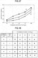
- Fig. 17 is a diagram illustrating the relation between the thickness ( ⁇ m) of the nozzle plate and an ejection voltage (V) applied to the electrode 34 in order to eject the ink.
- a graph 81 shown in Fig. 17 indicates maximum ejection voltages at which the ink can be ejected. Even applying an ejection voltage higher than the graph 81 to the electrode 34, the inkjet head 10 does not eject the ink from the integrated nozzle 35.
- the maximum ejection voltage at which the ink can be ejected increases as the thickness of the nozzle plate 23 increases.
- a graph 82 shown in Fig. 17 indicates minimum ejection voltages at which the ink can be ejected. Even applying an ejection voltage lower than the graph 82 to the electrode 34, the inkjet head 10 does not eject the ink from the integrated nozzle 35. As shown in Fig. 17 , the minimum ejection voltage at which the ink can be ejected increases as the thickness of the nozzle plate 23 increases.
- a graph 83 shown in Fig. 17 indicates ejection voltages at which a desired amount of the ink is ejected.
- the inkjet head 10 applies the ejection voltage of the graph 83 to the electrode 34 to eject a desired amount of the ink from the integrated nozzle 35.
- the ejection voltage at which the desired amount of the ink can be ejected increases as the thickness of the nozzle plate 23 increases.
- the width (an interval between the graph 81 and the graph 82) of the voltage at which the ink can be ejected is about 2V.
- the width of the voltage at which the ink can be ejected is wider than that of the voltage in a case in which the thickness of the nozzle plate 23 is 25 ⁇ m.
- the thickness of the nozzle plate 23 is equal to or higher than 35 ⁇ m.
- Fig. 18 is a diagram illustrating the relation between the thickness of the nozzle plate 23, and the diameter of the nozzle and the number of nozzles.
- Young's modulus of the nozzle plate 23 is 3-10Gpa.
- ⁇ indicates that the ejection failure does not occur.
- ⁇ indicates that the ejection failure occurs.
- ⁇ indicates that the ejection failure occurs sometimes.
- the thickness of the nozzle plate 23 is 25 ⁇ m, the ejection failure occurs. If the thickness of the nozzle plate 23 is 35 ⁇ m to 75 ⁇ m, the ejection failure does not occur. If the thickness of the nozzle plate 23 is 100 ⁇ m, the ejection failure occurs sometimes.
- the thickness of the nozzle plate 23 is 25 ⁇ m or 100 ⁇ m, the ejection failure occurs. If the thickness of the nozzle plate 23 is 35 ⁇ m to 75 ⁇ m, the ejection failure does not occur.
- the thickness of the nozzle plate 23 is 25 ⁇ m, the ejection failure occurs sometimes. If the thickness of the nozzle plate 23 is 35 ⁇ m to 75 ⁇ m, the ejection failure does not occur. If the thickness of the nozzle plate 23 is 100 ⁇ m, the ejection failure occurs.
- the thickness of the nozzle plate 23 is 25 ⁇ m, the ejection failure occurs sometimes. If the thickness of the nozzle plate 23 is 35 ⁇ m to 75 ⁇ m, the ejection failure does not occur. If the thickness of the nozzle plate 23 is 100 ⁇ m, the ejection failure occurs.
- the thickness of the nozzle plate 23 is 25 ⁇ m or 35 ⁇ m, the ejection failure occurs sometimes. If the thickness of the nozzle plate 23 is 50 ⁇ m to 100 ⁇ m, the ejection failure occurs.
- the inkjet head 10 is equipped with a nozzle plate 23 the thickness of which is 35 ⁇ m to 75 ⁇ m and on which an integrated nozzle 35 having a plurality of nozzles the diameter of each of which is 20 ⁇ m to 35 ⁇ m are formed.
- the control circuit 14 may apply the non-ejection pulse to the channel of the ejection area where the ink is not ejected similar to the first embodiment or may not apply the non-ejection pulse thereto.
- the inkjet head with foregoing structure is composed of a nozzle plate the Young's modulus of which is equal to or higher than 2Gpa and equal to or lower than 100Gpa. If the Young's modulus of the nozzle plate is lower than 2Gpa, unevenness of the density of the ink occurs such that the printing quality is reduced. If the Young's modulus of the nozzle plate is higher than 100Gpa, the following property to the adhesive surface of the driving element is lowered, and the high flatness is necessary. As a result, the increase of the process or the reduction of the yield rate occurs. Thus, the inkjet head according to the embodiment can prevent the unevenness of the density of the ink and prevent the increase of the process or the reduction of the yield rate.
- the inkjet head is composed of the nozzle plate the thickness of which is equal to or greater than 35 ⁇ m. As a result, the inkjet head can widen the width of the voltage at which the ink can be ejected.
- the inkjet head is composed of the nozzle plate 23 the thickness of which is 35 ⁇ m to 75 ⁇ m and which includes a plurality of nozzles the diameter of each of which is 20 ⁇ m to 35 ⁇ m.
- the inkjet head can reduce the ejection failure.
- the AL changes depending on the Young's modulus of the nozzle plate 23 and the hole diameter of the nozzle. For example, if the Young's modulus of the nozzle plate 23 becomes small and the hole diameter of the nozzle becomes small, AL becomes long. From this point, it is desired that the Young's modulus is equal to or smaller than 100Gpa and the hole diameter of the nozzle is equal to or smaller than 40 ⁇ m. On the other hand, if the AL is long, the driving period cannot be shortened and the printing at a high speed is difficultly realized. Thus, it is desired that the Young's modulus is equal to or higher than 2Gpa and the hole diameter of the nozzle is equal to or higher than 20 ⁇ m.
- a figure or a parameter from one range may be combined with another figure or a parameter from a different range for the same characteristic to generate a numerical range.
Landscapes
- Particle Formation And Scattering Control In Inkjet Printers (AREA)
Abstract
Description
- Embodiments described herein relate generally to an inkjet head and an inkjet printer, as well as an inkjet printing method.
- An inkjet head of an inkjet printer is equipped with a plurality of ejection areas including a plurality of nozzles. A plurality of the ejection areas ejects ink onto a print medium such as a paper at different timing. For example, the inkjet head ejects ink from a second ejection area after ejecting the ink from a first ejection area. In some cases, conventional inkjet heads undesirably fail to eject the ink from a next ejection area due to an effect of nozzle negative pressure generated in the initial ejection area.
- To solve such problems, there is provided an inkjet head comprising:
- a plurality of first driving elements comprising a plurality of first pressure chambers respectively communicating with a plurality of first integrated nozzles;
- a plurality of second driving elements comprising a plurality of second pressure chambers respectively communicating with a plurality of second integrated nozzles;
- a common liquid chamber configured to communicate with the plurality of the first pressure chambers and the plurality of the second pressure chambers; and
- a controller configured to apply an ejection pulse to the plurality of first driving elements and at least one non-ejection pulse to the plurality of second driving elements before an end timing of the ejection pulse.
- Preferably, the controller respectively divides a plurality of the first pressure chambers and a plurality of the second pressure chambers into a plurality of groups, applies the ejection pulse to one group of the first pressure chambers and applies the non-ejection pulse to one group of the second pressure chambers.
- Preferably still, a plurality of the second driving elements parallel to an arrangement direction of a plurality of the first driving elements is arranged; and
the first integrated nozzle and the second integrated nozzle are arranged alternately with respect to the arrangement direction. - Preferably yet, the non-ejection pulse is a rectangular pulse wave; and
a width of the non-ejection pulse is equal to or higher than one third of time equivalent to half of a natural vibration period in which the nozzle negative pressure of the first pressure chamber or the second pressure chamber changes. - Suitably, the plurality of first integrated nozzles and the plurality of second integrated nozzles are independently arranged in a longitudinal direction of a nozzle plate.
- Suitably yet, the inkjet head further comprises:
- a plurality of third driving elements comprising a plurality of third pressure chambers respectively communicating with a plurality of third integrated nozzles;
- the common liquid chamber configured to communicate with the plurality of the third pressure chambers, the plurality of the first pressure chambers, and the plurality of the second pressure chambers.
- The invention also relates to an inkjet printer comprising:
- an inkjet head as defined above; and
- a supply section configured to supply a print medium on which an image is formed through ink ejected from the inkjet head, wherein
- The invention further concerns an inkjet printing method comprising:
- applying an ejection pulse to a plurality of first driving elements comprising a plurality of first pressure chambers respectively communicating with a plurality of first integrated nozzles; and
- applying at least one non-ejection pulse to a plurality of second driving elements comprising a plurality of second pressure chambers respectively communicating with a plurality of second integrated nozzles before an end timing of the ejection pulse.
- Preferably, the ejection pulse comprises an expansion pulse and a contraction pulse.
- Preferably still, the ejection pulse comprises a waveform changing at a plurality of stages or a rectangular waveform.
- Preferably yet, the non-ejection pulse comprises a signal having a voltage smaller than a voltage of the signal of the ejection pulse.
- Suitably, the non-ejection pulse comprises a signal having a width smaller than a width of a signal of the ejection pulse.
- Suitably still, the non-ejection pulse comprises a rectangular pulse wave, and the non-ejection pulse wave is shorter than a rectangular pulse wave of the ejection pulse.
- Typically, a timing of the start of the ejection pulse is the same as the start of the non-ejection pulse.
- Typically still, the inkjet printing method further comprises:
- applying at least one non-ejection pulse to a plurality of third driving elements comprising a plurality of third pressure chambers respectively communicating with a plurality of third integrated nozzles before an end timing of the ejection pulse.
- The above and other objects, features and advantages of the present invention will be made apparent from the following description of the preferred embodiments, given as non-limiting examples, with reference to the accompanying drawings, in which:
-
Fig. 1 is a diagram illustrating an example of the configuration of an inkjet printer according to a first embodiment; -
Fig. 2 a perspective view of an inkjet head according to the first embodiment; -
Fig. 3 is a cross-sectional view of the inkjet head according to the first embodiment; -
Fig. 4 is an exploded perspective view illustrating the exploded inkjet head according to the first embodiment; -
Fig. 5 is a cross-sectional view of the inkjet head according to the first embodiment; -
Fig.6 is a plan view illustrating a nozzle plate from a first surface side according to the first embodiment; -
Fig. 7 is a cross-sectional view of the nozzle plate according to the first embodiment; -
Fig. 8 is a plan view illustrating the nozzle plate from a second surface side according to the first embodiment; -
Fig. 9 is a cross-sectional view of the inkjet head along a thickness direction of the nozzle plate according to the first embodiment; -
Fig. 10 is a diagram illustrating an example of operations of the inkjet head according to the first embodiment; -
Fig. 11 is a diagram illustrating an example of the operations of the inkjet head according to the first embodiment; -
Fig. 12 is a timing chart illustrating an example of a pulse applied to the inkjet head according to the first embodiment; -
Fig. 13 is a timing chart illustrating another example of the pulse applied to the inkjet head according to the first embodiment; -
Fig. 14 is a timing chart illustrating a concrete example of the pulse applied to the inkjet head according to the first embodiment; -
Fig. 15 is a diagram illustrating a relation between a non-ejection pulse width and ejection failure according to the first embodiment; -
Fig. 16 is a diagram illustrating another example of the inkjet printer according to the first embodiment; -
Fig. 17 is a diagram illustrating a relation between an ejection voltage and a thickness of the nozzle plate of an inkjet printer according to a second embodiment; and -
Fig. 18 is a diagram illustrating a relation between ejection failure and the configuration of a nozzle of the inkjet printer according to the second embodiment. - In accordance with an embodiment, an inkjet head comprises a plurality of first driving elements, a plurality of second driving elements, a common liquid chamber and a controller. A plurality of the first driving elements contains a plurality of first pressure chambers respectively communicating with a plurality of first integrated nozzles containing at least two nozzles. A plurality of the second driving elements contains a plurality of second pressure chambers respectively communicating with a plurality of second integrated nozzles containing at least two nozzles. The common liquid chamber communicates with a plurality of the first pressure chambers and a plurality of the second pressure chambers. The controller applies an ejection pulse to the first driving element and at least one non-ejection pulse to the second driving element before an end timing of the ejection pulse.
- In accordance with another embodiment,
- Hereinafter, the embodiment is described with reference to the accompanying drawings.
- First, a first embodiment is described.
-
Fig. 1 is a diagram illustrating an example of the configuration of aninkjet printer 100 according to the first embodiment. - The
inkjet printer 100 conveys a paper P as a print medium along a predetermined conveyance route while carrying out various processing such as an image forming processing and the like. Theinkjet printer 100 is equipped with aninkjet head 10, ahousing 110, apaper feed cassette 111 as a paper supply section, apaper discharge tray 112 as a discharge section, a holdingroller 113, aconveyance device 114 and a reversingdevice 118. - The
housing 110 constitutes the contour of theinkjet printer 100. Thepaper feed cassette 111 is arranged inside of thehousing 110. Thepaper feed cassette 111 stores the paper P. Thepaper discharge tray 112 is arranged above thehousing 110. Thepaper discharge tray 112 discharges the paper P on which an image is formed. - The holding roller 113 (drum) holds the paper P on the outer surface thereof to rotate. The
conveyance device 114 conveys the paper P along a predetermined conveyance path A1 formed from thepaper feed cassette 111 to thepaper discharge tray 112 via the outer circumference of the holdingroller 113. The reversingdevice 118 reverses front and rear surfaces of the paper P peeled from the holdingroller 113 to supply the reversed paper P to the surface of the holdingroller 113 again. - The
conveyance device 114 is equipped with a plurality of guide members and a plurality of rollers for conveyance arranged along the conveyance path A1. The rollers for conveyance include a pickup roller, a paper feed roller pair, a resist roller pair, a separation roller pair, a conveyance roller pair and a discharge roller pair. These rollers for conveyance are driven by a motor for conveyance to rotate to send the paper P to the downstream side along the conveyance path A1. - Sensors S for monitoring conveyance states of the paper are arranged in various places of the conveyance path A1. The holding
roller 113 rotates in a state of holding the paper P on the surface thereof to convey the paper P. - On the outer peripheral part of the holding
roller 113, a holdingdevice 115, ahead unit 116, adischarge peeling device 117 and acleaning device 119 are arranged in order from the upstream side to the downstream side. - The holding
device 115 is equipped with apressing roller 115a and a chargingroller 115b. Thepressing roller 115a presses the outer surface of the holdingroller 113. The chargingroller 115b generates (charges) electrostatic force of a direction in which the paper P is absorbed on the outer surface of the holdingroller 113 through supplied electric power. The holdingroller 113 absorbs the paper P through the electrostatic force. - The
head unit 116 includes a plurality of (four colors) inkjet heads 10 oppositely arranged on the outer surface of the holdingroller 113. For example, thehead unit 116 is equipped with acyan inkjet head 10C, amagenta inkjet head 10M, ayellow inkjet head 10Y and ablack inkjet head 10K. The inkjet heads 10C, 10M, 10Y and 10K respectively eject ink from nozzle holes arranged at a predetermined pitch. The inkjet heads 10C, 10M, 10Y and 10K discharge the ink to form an image on the paper P held on the outer surface of the holdingroller 113. The inkjet head 10 (10C, 10M, 10Y and 10K) is described in detail later. - The
discharge peeling device 117 is equipped with adischarge roller 117a for removing the electrostatic force of the paper P and a peelingclaw 117b for peeling the paper P from the holdingroller 113. - The
cleaning device 119 is equipped with a cleaningmember 119a that rotates in a state of contacting with the holdingroller 113 to clean the holdingroller 113. - The reversing
device 118 reverses the paper P peeled from the holdingroller 113 to supply the reversed paper P to the surface of the holdingroller 113 again. - The
inkjet printer 100 is further equipped with a controller, a ROM, a RAM and an I/F (interface). The controller (central control unit) is, for example, a processor such as a CPU. The ROM is a memory for storing various programs. The RAM is a memory for temporarily storing various variable data, image data and the like. The I/F (interface) inputs data from an external device or outputs data to the external device. Furthermore, theinkjet printer 100 may be further equipped with proper elements which are necessary or delete unnecessary elements. - Next, the
inkjet head 10 is described. Examples of the configuration of theinkjet head 10 are described hereinafter with reference toFig. 2 to Fig. 9 . Theinkjet head 10 receives the supply of the ink (print member) from theinkjet printer 100 to form an image on the paper P as the print medium. The print member may be various kinds of ink for forming images. Further, the print member may be functional ink including various functions used except the use of forming an image. - The
inkjet head 10 is connected with a tank (ink tank or liquid tank) loaded in theinkjet printer 100 via a tube. Theinkjet head 10 receives the supply of the ink from the tank via the tube. - The
inkjet head 10 is equipped with a headmain body 12, aunit section 13 and a control circuit 14 (controller or control section). The headmain body 12 is formed on theunit section 13. Thecontrol circuit 14, which is arranged on the side surface of theunit section 13, sends a control signal to the headmain body 12. Theunit section 13 includes a manifold for forming a part of a route between the headmain body 12 and the tank and a member for connecting with theinkjet printer 100. - As shown
Fig. 2 , thecontrol circuit 14 includes a substratemain body 15 and a pair of film carrier packages (FCP) 16. The substratemain body 15 is a rectangular printed wiring board. Various electronic components and connectors are mounted in the substratemain body 15. Further, a pair of theFCPs 16 is mounted in the substratemain body 15. - Each of the pair of the
FCPs 16 on which a plurality of wirings is formed includes a film made of resin having softness and anIC 17 connected with a plurality of the wirings. The film is tape automated bonding (TAB). The pair of theFCPs 16 is mounted from the substratemain body 15 along the side surface of theunit section 13 and connected with the headmain body 12. TheIC 17 is a member for applying a voltage to anelectrode 34. TheIC 17 is fixed on the film through the resin. -
Fig. 3 is a cross-sectional view of the inkjet head taken along a F3-F3 line according to the first embodiment. As shown inFig. 3 , an end part of theFCP 16 is connected with awiring pattern 21 on abase plate 22 by thermocompression bonding through an anisotropic conductive film (ACF). Through the ACF, a plurality of wirings of theFCP 16 is electrically connected with thewiring pattern 21. - The head
main body 12 ejects a liquid drop (ink drop) onto the print medium (paper P). As shown inFig. 3 , the headmain body 12 is equipped with thebase plate 22, anozzle plate 23, aframe member 24 and ablock 25 in which a plurality of drivingelements 31 is formed. - As shown in
Fig. 3 andFig. 4 , thebase plate 22 is formed into a rectangular plate shape. Thebase plate 22 is made from, for example, ceramic like alumina. A plurality of supply holes 26 and a plurality of discharge holes 27 penetrate thebase plate 22. - The supply holes 26 can be parallelly arranged substantially at the center of the
base plate 22 in a longitudinal direction of thebase plate 22. Thesupply hole 26 communicates with anink supply section 28 of the manifold of theunit section 13. Thesupply hole 26 is connected with the tank via theink supply section 28. - The discharge holes 27 are parallelly arranged at two sides of the
base plate 22 across thesupply hole 26 in the longitudinal direction of thebase plate 22. Thedischarge hole 27 communicates with anink discharge section 29 of the manifold of theunit section 13. Thedischarge hole 27 is connected with the tank via theink discharge section 29. - The
frame member 24 can be a square frame-shaped member. Theframe member 24 is made from, for example, nickel alloy. Theframe member 24 intermediates between thebase plate 22 and thenozzle plate 23. Theframe member 24 is respectively bonded with a mounting surface and thenozzle plate 23. - The driving
element 31 is formed by two piezoelectric bodies. The drivingelement 31 includes two plate-like piezoelectric bodies formed by, for example, lead zirconate titanate (PZT). The two piezoelectric bodies are bonded with each other in such a manner that their directions of polarization are opposite to each other in the thickness direction. - The
block 25 in which a plurality of the drivingelements 31 is formed is bonded on the mounting surface of thebase plate 22. As shown inFig. 3 , theblock 25 is formed into a trapezoid. The top of the drivingelement 31 is bonded with thenozzle plate 23. - As shown in
Fig. 4 , theblock 25 includes a plurality of grooves. The grooves respectively extend in a direction crossing with the longitudinal direction of the block 25 (longitudinal direction of the inkjet head 10). The plate-like driving elements 31 are separated by the grooves. -
Fig. 5 is a cross-sectional view of theinkjet head 10 taken along a F5-F5 line. As shown inFig. 5 , theelectrode 34 is arranged on both surfaces of the drivingelement 31. Theelectrode 34 covers the bottom of the groove (pressure chamber 32) and side surfaces of the drivingelement 31. Theelectrode 34 is formed by, for example, carrying out laser patterning on nickel thin film. Theelectrode 34 is electrically connected with theIC 17. - As shown in
Fig. 4 , a plurality of thewiring patterns 21 extending in a direction crossing with the longitudinal direction of thebase plate 22 from a plurality of the drivingelements 31 is arranged on the mounting surface of thebase plate 22. Thewiring pattern 21 is formed by, for example, carrying out the laser patterning on the nickel thin film formed on thebase plate 22. - The
nozzle plate 23 is formed with, for example, polyimide film, and is substantially rectangular. Thenozzle plate 23 faces thebase plate 22. Thenozzle plate 23 includes afirst surface 23A (pressure chamber surface) at apressure chamber 32 side and asecond surface 23B (outer surface) opposite to thefirst surface 23A. - The
nozzle plate 23 includes anintegrated nozzle 35. Theintegrated nozzle 35 penetrates thenozzle plate 23. Theintegrated nozzle 35 is composed of a firstintegrated nozzle 35a and a secondintegrated nozzle 35b. The firstintegrated nozzle 35a and the secondintegrated nozzle 35b are respectively composed of at least two nozzles. In other words, the firstintegrated nozzle 35a is composed of at least two of the nozzles formed in thenozzle plate 23. Further, the secondintegrated nozzle 35b is composed of at least two of the other nozzles formed in thenozzle plate 23. The number of the nozzles constituting theintegrated nozzle 35 is not specifically limited. In the example shown inFig. 4 , the firstintegrated nozzle 35a and the secondintegrated nozzle 35b are respectively composed of two nozzles arranged in parallel in a lateral direction of thenozzle plate 23. - The
nozzle plate 23 includes a plurality of the firstintegrated nozzles 35a and a plurality of the secondintegrated nozzles 35b. A plurality of the firstintegrated nozzles 35a and a plurality of the secondintegrated nozzles 35b are respectively arranged in parallel along the longitudinal direction of thenozzle plate 23. - An area inside the groove arranged in the
block 25 is thepressure chamber 32 facing afirst nozzle 36 and asecond nozzle 37 described later. A drivingelement 31 enables the liquid drops to be simultaneously ejected from thefirst nozzle 36 and thesecond nozzle 37 described later. Acommon liquid chamber 33 supplies the liquid (ink) to eachpressure chamber 32. As shown inFig. 3 , thecommon liquid chamber 33 is composed of thenozzle plate 23, a part of thebase plate 22 in the vicinity of thesupply hole 26 and the inclined plane portion of theblock 25. Thecommon liquid chamber 33 communicates with eachpressure chamber 32. - As shown in
Fig. 4 andFig. 5 , eachintegrated nozzle 35 includes thefirst nozzle 36 and thesecond nozzle 37. Thesecond nozzle 37 is arranged in the vicinity of thefirst nozzle 36 adjacent to thefirst nozzle 36 in the lateral direction of thenozzle plate 23. Thefirst nozzle 36 and thesecond nozzle 37 face thesame pressure chamber 32. - As shown in
Fig. 5 , theinkjet head 10 is equipped with two rows (a plurality of rows) of drivingelements 31 including one row ofplural driving elements 31a and one row ofplural driving elements 31b, arranged in one direction, which are parallel to each other. InFig. 5 , theinkjet head 10 is equipped with the drivingelements 31a as the row at the left side and the drivingelements 31b as the row at the right side. The longitudinal direction of the drivingelement 31 has an orthogonal relation to an arrangement direction of the driving element; however, the longitudinal direction of the drivingelements 31 may have a predetermined angle to the arrangement direction. Furthermore, the plural nozzles of theintegrated nozzle 35 are arranged in a direction parallel to the longitudinal direction of the driving elements. - Two rows of
ejection areas supply hole 26. Theejection area 51a is a first ejection area, and theejection area 51b is a second ejection area. Theejection area 51a and theejection area 51b are arranged at a predetermined interval. Theejection area 51a includes a plurality of thedriving elements 31a, theelectrodes 34a and the firstintegrated nozzles 35a. Theejection area 51b includes a plurality of the drivingelements 31b, theelectrodes 34b and the secondintegrated nozzles 35b. - The pressure chamber 32 (32a or 32b) is formed between the driving elements 31 (31a or 31b). The
pressure chamber 32 is formed by two drivingelements 31 and the electrodes 34 (34a or 34b) arranged on two surfaces of the drivingelement 31. Theintegrated nozzle 35 for ejecting the ink is arranged substantially at the center of the longitudinal direction of thepressure chamber 32 on thenozzle plate 23. The longitudinal direction of thepressure chamber 32 is orthogonal to the arrangement direction of the drivingelement 31. Thecommon liquid chamber 33 is arranged between theejection area 51a and theejection area 51b. Thedischarge hole 27 at one end side of theejection area 51a and thesupply hole 26 at the other end side thereof are arranged on thebase plate 22. Thesupply hole 26 at one end side of theejection area 51b and thedischarge hole 27 at the other end side thereof are arranged on thebase plate 22. A plurality of the supply holes 26 is arranged in the arrangement direction of the drivingelement 31. A plurality of rows of the plural discharge holes 27 is arranged in the arrangement direction of the drivingelement 31. Thedischarge hole 27 is arranged in the vicinity of theframe member 24. - The first
integrated nozzle 35a communicates with thepressure chamber 32a (first pressure chamber) formed by the drivingelements 31a (first driving elements) and theelectrodes 34a arranged on the both surfaces of the drivingelement 31a. Further, the secondintegrated nozzle 35b communicates with thepressure chamber 32b (second pressure chamber) formed by the drivingelements 31b (second driving elements) and theelectrodes 34b arranged on the both surfaces of the drivingelement 31b. - The first
integrated nozzle 35a in theejection area 51a and the secondintegrated nozzle 35b in theejection area 51b are not arranged collinearly with respect to a direction orthogonal to the arrangement direction of the drivingelement 31. In other words, the firstintegrated nozzle 35a in theejection area 51a and the secondintegrated nozzle 35b in theejection area 51b are arranged at positions different from each other with respect to the arrangement direction of the drivingelement 31. - Next, the first
integrated nozzle 35a and the secondintegrated nozzle 35b are described. Herein, the configuration of the firstintegrated nozzle 35a is described. As the configuration of the secondintegrated nozzle 35b is the same as that of the firstintegrated nozzle 35a, the description thereof is omitted. -
Fig. 6 is a diagram illustrating an example of afirst surface 23A of thenozzle plate 23.Fig. 7 is a cross-sectional view illustrating of thenozzle plate 23 taken along a F7-F7 line.Fig. 8 is a diagram illustrating an example of asecond surface 23B of thenozzle plate 23. - As shown in
Fig. 7 , the firstintegrated nozzle 35a is equipped with afirst nozzle 36a and asecond nozzle 37a. Thefirst nozzle 36a and thesecond nozzle 37a have the same shape. Thefirst nozzle 36a and thesecond nozzle 37a are formed into, for example, a trapezoid the diameter of which becomes small with approaching thesecond surface 23B. The firstintegrated nozzle 35a penetrates thefirst surface 23A and thesecond surface 23B. Thefirst nozzle 36a includes a first opening 36Aa arranged on thefirst surface 23A and a second opening 36Ba arranged on thesecond surface 23B. Thesecond nozzle 37a includes a third opening 37Aa arranged on thefirst surface 23A and a fourth opening 37Ba arranged on thesecond surface 23B. - A first peripheral surface 36Ca (inner peripheral surface, side surface and inclined surface) of the
first nozzle 36a linearly extends from thesecond surface 23B towards thefirst surface 23A. The first peripheral surface 36Ca (inner peripheral surface, side surface and inclined surface) of thefirst nozzle 36a crosses with a second peripheral surface 37Ca (inner peripheral surface, side surface and inclined surface) of thesecond nozzle 37a linearly extending from thesecond surface 23B towards thefirst surface 23A en route from thesecond surface 23B to thefirst surface 23A. - As shown in
Fig. 6 , a part of the first opening 36Aa is overlapped with a part of the third opening 37Aa. In other words, the first opening 36Aa and the third opening 37Aa are consecutively arranged. Thus, as shown inFig. 7 , a part of thefirst nozzle 36a at thefirst surface 23A side communicates with a part of thesecond nozzle 37a at thefirst surface 23A side to be integrated. - As shown in
Fig. 8 , the second opening 36Ba is separated from the fourth opening 37Ba but arranged in the vicinity of the fourth opening 37Ba. Thus, a part of thefirst nozzle 36a at thesecond surface 23B side is separated from a part of thesecond nozzle 37a at thesecond surface 23B side. - The second
integrated nozzle 35b is equipped with athird nozzle 36b and afourth nozzle 37b. Thethird nozzle 36b is equipped with a fifth opening 36Ab and a sixth opening 36Bb. Thefourth nozzle 37b is equipped with a seventh opening 37Ab and an eighth opening 37Bb. Thethird nozzle 36b, thefourth nozzle 37b, the fifth opening 36Ab, the sixth opening 36Bb, the seventh opening 37Ab and the eighth opening 37Bb are respectively the same as thefirst nozzle 36a, thesecond nozzle 37a, the first opening 36Aa, the second opening 36Ba, the third opening 37Aa and the fourth opening 37Ba, and thus, the description thereof is omitted. - Furthermore, the
first nozzle 36a and thesecond nozzle 37a may be independent of each other without communicating with each other. In other words, thefirst nozzle 36a and thesecond nozzle 37a do not communicate with each other at thefirst surface 23A side, at thesecond surface 23B side and between the two surfaces. Similarly, thethird nozzle 36b and thefourth nozzle 37b may be independent of each other without communicating with each other. In other words, thethird nozzle 36b and thefourth nozzle 37b do not communicate with each other at thefirst surface 23A side, at thesecond surface 23B side and between the two surfaces. - In the
inkjet head 10, partition may be arranged between eachpressure chamber 32 in theejection area 51a and eachpressure chamber 32 in theejection area 51b. In this case, theinkjet head 10 is equipped with the supply holes respectively at theejection area 51a side and at theejection area 51b side. The two supply holes communicate with the same common ink chamber. The common ink chamber may be formed at back surface side (in other words, outer surface side of the base plate 22) of thepressure chamber 32. The shape and position of the common ink chamber are not limited to a specific configuration. - Next, ejection operations of the ink by the
inkjet head 10 are described. Theinkjet head 10 is a liquid (ink) circulationtype inkjet head 10. The ink ejected from the tank is supplied to the pressure chamber 32 (32a and 32b) via thesupply hole 26 and thecommon liquid chamber 33. The ink which is not ejected in thepressure chamber 32 is collected from thedischarge hole 27 to the tank. In this way, in theinkjet head 10, the ink is circulated between the tank and the inside of theinkjet head 10. - The ejection operations of the first
integrated nozzle 35a and the secondintegrated nozzle 35b are identical, and thus, only the ejection operations of the firstintegrated nozzle 35a are described hereinafter and the ejection operations of the secondintegrated nozzle 35b are omitted. -
Fig. 9 is a cross-sectional view of thepressure chamber 32a along the thickness direction of thenozzle plate 23. Thecontrol circuit 14 drives the drivingelement 31a to increase or decrease the volume of thepressure chamber 32a in order to enable the ink to be ejected from the firstintegrated nozzle 35a. Thecontrol circuit 14 applies a voltage to theelectrode 34a to drive the drivingelement 31a to increase or decrease the volume of thepressure chamber 32a. -
Fig. 10 is a diagram illustrating a state in which thecontrol circuit 14 drives the drivingelement 31a so as to increase the volume of thepressure chamber 32a. For example, thecontrol circuit 14 applies a pulse (expansion pulse) which expands the volume of thepressure chamber 32a to the drivingelement 31a. If thecontrol circuit 14 applies the expansion pulse to the drivingelement 31a, as shown inFig. 10 , the drivingelement 31a deforms towards the outer side of thepressure chamber 32a. As a result, the volume of thepressure chamber 32a is increased compared with the initial state (state inFig. 9 ). -
Fig. 11 is a diagram illustrating a state in which thecontrol circuit 14 drives the drivingelement 31a so as to decrease the volume of thepressure chamber 32a. For example, thecontrol circuit 14 applies a pulse (contraction pulse) which contracts the volume of thepressure chamber 32a to the drivingelement 31a. If thecontrol circuit 14 applies the contraction pulse to the drivingelement 31a, as shown inFig. 11 , the drivingelement 31a deforms towards the inside of thepressure chamber 32a. As a result, the volume of thepressure chamber 32a is decreased compared with the initial state (state inFig. 9 ). - After the
control circuit 14 temporarily increases the volume of thepressure chamber 32a, if the volume of thepressure chamber 32a is smaller than the original volume, the liquid in thepressure chamber 32a is pressurized, and the ink from thefirst nozzle 36a and thesecond nozzle 37a is simultaneously ejected. In other words, thecontrol circuit 14 applies an ejection pulse composed of the expansion pulse and the contraction pulse to theelectrode 34 of the drivingelement 31a to enable the ink to be ejected. Further, the waveform of the ejection pulse may be, for example, a waveform changing at a plurality of stages or a rectangular waveform. The configuration of the ejection pulse is not limited to the specific configuration. - Just before the ejection of the ink, meniscus surfaces 43a of the
first nozzle 36a and thesecond nozzle 37a protrude towards the external. The ejected ink is ejected as the liquid drop towards the print medium. After the liquid drop is ejected, themeniscus surface 43a of thefirst nozzle 36a and themeniscus surface 43a of thesecond nozzle 37a retreat towards the inside of thefirst nozzle 36a and thesecond nozzle 37a. - Next, an example of operations of the
control circuit 14 is described. As shown inFig. 5 , thecontrol circuit 14 sets theejection area 51a and theejection area 51b. Theejection area 51a includes one row of the firstintegrated nozzles 35a (e.g., a row at the left side ofFig. 5 ) which are arranged in the longitudinal direction of thenozzle plate 23. Similarly, theejection area 51b includes a row of the secondintegrated nozzles 35b (e.g., a row at the right side ofFig. 5 ) arranged in the longitudinal direction of thenozzle plate 23. - The
control circuit 14 enables the ink to be ejected from theintegrated nozzle 35 in each ejection area. For example, at the time the print medium passes from theejection area 51a side, thecontrol circuit 14 enables the ink to be ejected from theejection area 51a, and sequentially enables the ink to be ejected from theejection area 51b. - Further, the
control circuit 14 sets a channel No for each pressure chamber 32 (channel) in thepredetermined ejection areas control circuit 14 sets the channel No of eachpressure chamber 32 in order from one end of thenozzle plate 23. - The
pressure chamber 32 shares the drivingelement 31 with the respectivelyadjacent pressure chambers 32. Thus, thecontrol circuit 14 cannot drive eachpressure chamber 32 at the same time. Consequently, thecontrol circuit 14 divides thepressure chambers 32 into a plurality of groups every n+1 (n is an integer equal to or greater than 2) channels to drive each group (division). In the embodiment, thecontrol circuit 14 divides thepressure chambers 32 into three groups every three channels to carry out division driving, in other words, a case of three division driving is exemplified. - The
control circuit 14 divides thepressure chambers 32 into No. 3n-2 channel group (first division), No. 3n-1 channel group (second division) and No. 3n channel group (third division) (n is an integer equal to or greater than 1). For example, thecontrol circuit 14 enables the ink to be ejected in the order of the first division, the second division and the third division. - Further, the
control circuit 14 may adopt a method (Multi-drop drive) for enabling the ink to be continuously ejected from one channel for many times. For example, thecontrol circuit 14 controls the times that the ink is continuously ejected in response to print data. - Next, the pulse applied to the channel by the
control circuit 14 is described.Fig. 12 is a timing chart illustrating an example of the pulse applied to the channel by thecontrol circuit 14. Thecontrol circuit 14 enables the ink to be ejected from a predetermined division of theejection area 51b after enabling the ink to be ejected from a predetermined division of theejection area 51a. - A waveform a exemplifies a pulse applied to a predetermined division (division a) of the
ejection area 51a. A waveform b exemplifies a pulse applied to a division (division b) of theejection area 51b corresponding to the predetermined division of theejection area 51a. - As shown in
Fig. 12 , thecontrol circuit 14 applies anejection pulse 61a to the division a at a predetermined timing. Further, thecontrol circuit 14 sequentially appliesnon-ejection pulses 62b to 64b to the division b and then applies theejection pulse 61b thereto. - The non-ejection pulse is a signal which does not lead to the ejection of the ink. In other words, the non-ejection pulse is a signal which enables the
pressure chamber 32 to generate vibration but does not lead to the ejection of the ink. For example, the non-ejection pulse is a signal of which a voltage is smaller than that of the ejection pulse. Further, the non-ejection pulse is a signal of which a width is smaller than that of the ejection pulse. For example, the non-ejection pulse is a rectangular pulse wave. The waveform of the non-ejection pulse is not limited to the specific configuration. In the present embodiment, the non-ejection pulse is set to the rectangular pulse wave. Furthermore, the non-ejection pulse is set to a pulse wave shorter than the ejection pulse. - The
control circuit 14 applies at least one non-ejection pulse to the division b until the application of the ejection pulse to the division a is ended. In other words, thecontrol circuit 14 applies a non-ejection pulse to the division b of which the application is ended until an end timing at which the application of the ejection pulse to the division a is ended. - In the example shown in
Fig. 12 , thecontrol circuit 14 starts to apply thenon-ejection pulse 62b to the division b at a timing when the application of theejection pulse 61a to the division a is started. In other words, thecontrol circuit 14 makes the timing of the start of theejection pulse 61a of the division a consistent with the timing of the start of thenon-ejection pulse 62b of the division b. - After applying the
non-ejection pulse 62b to the division b, thecontrol circuit 14 applies thenon-ejection pulse 63b to the division b at a predetermined interval. After applying thenon-ejection pulse 63b to the division b, thecontrol circuit 14 applies thenon-ejection pulse 64b to the division b at a predetermined interval. After applying thenon-ejection pulse 64b to the division b, thecontrol circuit 14 applies theejection pulse 61b to the division b at a predetermined interval. - The interval between the
non-ejection pulse 62b and thenon-ejection pulse 63b may be identical to or different from that between thenon-ejection pulse 63b and thenon-ejection pulse 64b. Thecontrol circuit 14 may apply three or more non-ejection pulses or only one non-ejection pulse between thenon-ejection pulse 62b and theejection pulse 61b. Further, thecontrol circuit 14 may not apply a non-ejection pulse between thenon-ejection pulse 62b and theejection pulse 61b. Further, thecontrol circuit 14 may apply a non-ejection pulse prior to thenon-ejection pulse 62b. - Next, another example of the pulse applied to the channel by the
control circuit 14 is described.Fig. 13 is a timing chart illustrating another example of the pulse applied to the channel by thecontrol circuit 14. Thecontrol circuit 14 enables the ink to be ejected from the predetermined division of theejection area 51b after enabling the ink to be ejected from the predetermined division of theejection area 51a. - As shown in
Fig. 13 , thecontrol circuit 14 applies anejection pulse 71a to the division a at a predetermined timing. Further, thecontrol circuit 14 sequentially appliesnon-ejection pulses 72b to 74b to the division b, and then applies anejection pulse 71b thereto. - In the example shown in
Fig. 13 , thecontrol circuit 14 applies thenon-ejection pulse 72b to the division b at a predetermined timing before applying theejection pulse 71a to the division a. If thenon-ejection pulse 72b is applied to the division b, thecontrol circuit 14 applies thenon-ejection pulse 73b of which the application is ended at the same timing as the end of the application of theejection pulse 71a to the division a. In other words, thecontrol circuit 14 makes the timing of the falling of theejection pulse 71a of the division a consistent with the timing of the falling of thenon-ejection pulse 73b. - If the
non-ejection pulse 73b is applied to the division b, thecontrol circuit 14 applies anon-ejection pulse 74b to the division b at a predetermined interval. If anon-ejection pulse 74b is applied to the division b, thecontrol circuit 14 applies theejection pulse 71b to the division b at a predetermined interval. - The interval between the
non-ejection pulse 72b and thenon-ejection pulse 73b may be identical to or different from that between thenon-ejection pulse 73b and thenon-ejection pulse 74b. Thecontrol circuit 14 may apply two or more non-ejection pulses or may not apply any non-ejection pulse between thenon-ejection pulse 73b and theejection pulse 71b. Thecontrol circuit 14 may apply two or more non-ejection pulses or may not apply any non-ejection pulse before thenon-ejection pulse 73b. Further, thecontrol circuit 14 may apply a plurality of non-ejection pulses to the division b while an ejection pulse is applied to the division a. - Next, the pulses applied to each division of the
ejection area 51a and each division of theejection area 51b by thecontrol circuit 14 are described. -
Fig. 14 is a timing chart for describing a concrete example of the pulses applied to each division of theejection area 51a and each division of theejection area 51b by thecontrol circuit 14.Fig. 14 illustrates an example (example shown inFig. 13 ) in which a timing at which the ejection pulse is ended is consistent with a timing at which the non-ejection pulse is ended. - It is assumed that the
control circuit 14 enables the ink to be ejected from each division of theejection area 51a, and next enables the ink to be ejected from each division of theejection area 51a and each division of theejection area 51b. Thecontrol circuit 14 enables the ink to be ejected from the first division, the second division and the third division in order. - In
Fig. 14 , a waveform a1 illustrates an example of a pulse applied to the first division of theejection area 51a. A waveform a2 illustrates an example of a pulse applied to the second division of theejection area 51a. A waveform a3 illustrates an example of a pulse applied to the third division of theejection area 51a. A waveform b1 illustrates an example of a pulse applied to the first division of theejection area 51b. A waveform b2 illustrates an example of a pulse applied to the second division of theejection area 51b. A waveform b3 illustrates an example of a pulse applied to the third division of theejection area 51b. - As shown in
Fig. 14 , firstly, thecontrol circuit 14 applies an ejection pulse to the first division of theejection area 51a. Further, thecontrol circuit 14 applies a non-ejection pulse to the first division of theejection area 51b of which the application is ended at the same timing as the end of the application of the ejection pulse. - If the ejection pulse is applied to the first division of the
ejection area 51a and the non-ejection pulse is applied to the first division of theejection area 51b, thecontrol circuit 14 applies an ejection pulse to the second division of theejection area 51a. Further, thecontrol circuit 14 applies a non-ejection pulse to the second division of theejection area 51b of which the application is ended at the same timing as the end of the application of the ejection pulse. - If the ejection pulse is applied to the second division of the
ejection area 51a and the non-ejection pulse is applied to the second division of theejection area 51b, thecontrol circuit 14 applies an ejection pulse to the third division of theejection area 51a. Further, thecontrol circuit 14 applies a non-ejection pulse to the third division of theejection area 51b of which the application is ended at the same timing as the end of the application of the ejection pulse. - Similarly, the
control circuit 14 applies the ejection pulses to the first division, the second division and the third division of theejection area 51a. Further, similarly, thecontrol circuit 14 applies the non-ejection pulse to the first division, the second division and the third division of theejection area 51b. - Further, the
control circuit 14 simultaneously applies the ejection pulse to the first division of theejection area 51b and the ejection pulse to the first division of theejection area 51a at a predetermined timing. For example, thecontrol circuit 14 applies the ejection pulses to the first divisions of both ejection areas at a timing when the paper P is conveyed to a position where theejection area 51b ejects the ink. If the ejection pulses are applied to the first divisions of both ejection areas, thecontrol circuit 14 applies the ejection pulses to the second divisions of both ejection areas. If the ejection pulses are applied to the second divisions of both ejection areas, thecontrol circuit 14 applies the ejection pulses to the third divisions of both ejection areas. - Furthermore, the
control circuit 14 may not apply the ejection pulse to a predetermined division of theejection area 51a at a predetermined timing. For example, thecontrol circuit 14 may apply a non-ejection pulse to the predetermined division of theejection area 51a before an end timing of the ejection pulse applied to a predetermined division of theejection area 51b. - In a case in which ink drops are ejected the number of which meets the maximum ejection number from a predetermined channel, the
control circuit 14 may apply the non-ejection pulse to an empty part of the ejection pulse (in other words, at the timing of applying the ejection pulse in a case of ejecting the maximum ejection number). Further, thecontrol circuit 14 may apply the non-ejection pulse to a part of the empty part. - Next, a relation between a width of the non-ejection pulse and ejection failure is described.
- Firstly, ejection failure generated in the
inkjet head 10 is described. - According to the embodiment, the
inkjet head 10 is equipped with theejection areas inkjet head 10 ejects the ink ahead from either of theejection areas inkjet head 10 ejects the ink from an initial ejection area (for example, theejection area 51a), pressure (nozzle negative pressure) of thepressure chamber 32 of the ejection area, thecommon liquid chamber 33 communicating with the pressure chamber and thepressure chamber 32 of the other ejection area (for example, theejection area 51b) communicating with thecommon liquid chamber 33 is reduced. - In a case of ejecting the ink from the
ejection area 51b after ejecting the ink from theejection area 51a, theinkjet head 10 ejects the ink from theejection area 51b in most cases in a state in which the nozzle negative pressure is lower than that before the ejection of the ink. If theinkjet head 10 ejects the ink in a state in which the nozzle negative pressure is lower, the first ejection failure (for example, blurring or decrease in an ejection volume) occurs in most cases. In other words, theinkjet head 10 is easy to generate the first ejection failure if the nozzle negative pressure before the ejection of the ink is low. - Further, in a case in which there is a plurality of nozzles (the
first nozzle 36 and the second nozzle 37) with respect to onepressure chamber 32, the second ejection failure (e.g., blurring) occurs in most cases. If the nozzle negative pressure is high, the second ejection failure occurs. In other words, theinkjet printer 10 is easy to generate the second ejection failure if the nozzle negative pressure before the ejection of the ink is high. -
Fig. 15 is a diagram illustrating a relation between a non-ejection pulse width and the ejection failure. The horizontal axis inFig. 15 indicates the width of the non-ejection pulse. AL refers to time equivalent to half of the natural vibration period in which the nozzle negative pressure changes. The vertical axis inFig. 15 indicates the nozzle negative pressure before the ejection. - A
graph 61 shown inFig. 15 indicates the nozzle negative pressure at which the first ejection failure occurs. In other words, if the nozzle negative pressure is lower than the graph 61 (a case of being at the lower side of the graph 61), the first ejection failure occurs. Contrarily, if the nozzle negative pressure is higher than the graph 61 (a case of being at the upper side of the graph 61), the first ejection failure does not occur. - A
graph 62 shown inFig. 15 indicates the nozzle negative pressure at which the second ejection failure occurs. In other words, if the nozzle negative pressure is higher than the graph 62 (a case of being at the upper area of the graph 62), the second ejection failure occurs. Contrarily, if the nozzle negative pressure is lower than the graph 62 (a case of being at the lower area of the graph 62), the first ejection failure does not occur. - The nozzle negative pressure and the width of the non-ejection pulse at which the first and the second ejection failure does not occur are at the upper area of the
graph 61 and at the lower area of thegraph 62. As shown inFig. 15 , if the width of the non-ejection pulse is longer than or equal to 1/3AL, theinkjet head 10 can set the nozzle negative pressure at which the first and the second ejection failure does not occur. - Next, another embodiment relating to the
inkjet head 10 according to the first embodiment is described.Fig. 16 is a diagram for illustrating another embodiment. Theinkjet head 10 according to another embodiment is further equipped with aliquid repellent layer 70. The other points of theinkjet head 10 according to another embodiment are the same as those of theinkjet head 10 according to the first embodiment, and thus, the same symbols are assigned thereto and the description thereof is omitted. - The
liquid repellent layer 70 is formed on thesecond surface 23B. Theliquid repellent layer 70 is at least formed around theintegrated nozzle 35 on thesecond surface 23B. Theliquid repellent layer 70 is formed by material having a liquid repellent property. The thickness of theliquid repellent layer 70 is, for example, equal to or smaller than 1 µm. - The
liquid repellent layer 70 is formed by, for example, fluorine or silica-based material. The material or the shape of theliquid repellent layer 70 is not limited to a specific configuration. Theliquid repellent layer 70 is formed by, for example, executing vapor deposition on thesecond surface 23B. - The inkjet head with the foregoing structure can apply the non-ejection pulse to the channel of the ejection area where the ink is not ejected at a timing when the ejection pulse is applied. As a result, the inkjet head can suppress the ejection failure (the first ejection failure) generated due to decrease of the nozzle negative pressure. As the negative pressure setting can be lowered through applying the non-ejection pulse, the inkjet head can also suppress the ejection failure (the second ejection failure) generated in a case in which there is a plurality of nozzles (the
first nozzle 36 and the second nozzle 37) with respect to onepressure chamber 32. Thus, the inkjet head can set the nozzle negative pressure at which the first and the second ejection failure does not occur through applying the non-ejection pulse. Thus, the inkjet head can suppress the ejection failure. - The inkjet head easily generates the second ejection failure if the ink adheres to the vicinity of the nozzle. The inkjet head according to the embodiment forms the liquid repellent layer having the liquid repellent property in the vicinity of the nozzle. With the liquid repellent layer, the inkjet head can suppress the adhesion of the ink to the vicinity of the nozzle. Thus, the inkjet head can suppress the adhesion of the ink to the vicinity of the nozzle without largely reducing the nozzle negative pressure, thereby suppressing the ejection failure. Further, the inkjet head can suppress the ejection failure even without increasing the width of the non-ejection pulse.
- Next, the second embodiment is described. The number of the nozzles included in the integrated nozzle of the inkjet printer according to the second embodiment is 2 to 6, which is different from that of the inkjet printer according to the first embodiment. The same symbols are assigned to the other components and the description thereof is omitted.
- The
nozzle plate 23 is formed by material the Young's modulus of which is higher than or equal to 2Gpa and is lower than or equal to 100Gpa. The diameter of each of thefirst nozzle 36 and thesecond nozzle 37 is about 35µm. The diameter of each of the second opening 36B and the fourth opening 37B is about 35µm. - The
inkjet head 10 ejects 10pL or more every one drop (a liquid drop ejected from thefirst nozzle 36 and thesecond nozzle 37 in a single operation). As stated above, theinkjet head 10 includes two nozzles (thefirst nozzle 36 and the second nozzle 37), thus theinkjet head 10 ejects 20pL or more in the single ejection operation from eachpressure chamber 32. -
Fig. 17 is a diagram illustrating the relation between the thickness (µm) of the nozzle plate and an ejection voltage (V) applied to theelectrode 34 in order to eject the ink. Agraph 81 shown inFig. 17 indicates maximum ejection voltages at which the ink can be ejected. Even applying an ejection voltage higher than thegraph 81 to theelectrode 34, theinkjet head 10 does not eject the ink from theintegrated nozzle 35. As shown inFig. 17 , the maximum ejection voltage at which the ink can be ejected increases as the thickness of thenozzle plate 23 increases. - A
graph 82 shown inFig. 17 indicates minimum ejection voltages at which the ink can be ejected. Even applying an ejection voltage lower than thegraph 82 to theelectrode 34, theinkjet head 10 does not eject the ink from theintegrated nozzle 35. As shown inFig. 17 , the minimum ejection voltage at which the ink can be ejected increases as the thickness of thenozzle plate 23 increases. - A
graph 83 shown inFig. 17 indicates ejection voltages at which a desired amount of the ink is ejected. Theinkjet head 10 applies the ejection voltage of thegraph 83 to theelectrode 34 to eject a desired amount of the ink from theintegrated nozzle 35. As shown inFig. 17 , the ejection voltage at which the desired amount of the ink can be ejected increases as the thickness of thenozzle plate 23 increases. - As shown in
Fig. 17 , in a case in which the thickness of thenozzle plate 23 is 25µm, the width (an interval between thegraph 81 and the graph 82) of the voltage at which the ink can be ejected is about 2V. On the other hand, in a case in which the thickness of thenozzle plate 23 is equal to or higher than 35µm, the width of the voltage at which the ink can be ejected is wider than that of the voltage in a case in which the thickness of thenozzle plate 23 is 25µm. Thus, in order to ensure the width of the voltage at which the ink can be ejected, the thickness of thenozzle plate 23 is equal to or higher than 35µm. - Next, the relation between the thickness of the
nozzle plate 23, and the diameter of the nozzle and the number of nozzles is described.Fig. 18 is a diagram illustrating the relation between the thickness of thenozzle plate 23, and the diameter of the nozzle and the number of nozzles. In the example shown inFig. 18 , Young's modulus of thenozzle plate 23 is 3-10Gpa. InFig. 18 , "○" indicates that the ejection failure does not occur. "×" indicates that the ejection failure occurs. "Δ" indicates that the ejection failure occurs sometimes. - In a case in which the diameter of the nozzle is 35 µm and there are two nozzles, if the thickness of the
nozzle plate 23 is 25µm, the ejection failure occurs. If the thickness of thenozzle plate 23 is 35µm to 75µm, the ejection failure does not occur. If the thickness of thenozzle plate 23 is 100µm, the ejection failure occurs sometimes. - In a case in which the diameter of the nozzle is 30µm and there are three nozzles, if the thickness of the
nozzle plate 23 is 25µm or 100µm, the ejection failure occurs. If the thickness of thenozzle plate 23 is 35µm to 75µm, the ejection failure does not occur. - In a case in which the diameter of the nozzle is 25 µm and there are four nozzles, if the thickness of the
nozzle plate 23 is 25µm, the ejection failure occurs sometimes. If the thickness of thenozzle plate 23 is 35µm to 75µm, the ejection failure does not occur. If the thickness of thenozzle plate 23 is 100µm, the ejection failure occurs. - In a case in which the diameter of the nozzle is 20µm and there are five nozzles, if the thickness of the
nozzle plate 23 is 25µm, the ejection failure occurs sometimes. If the thickness of thenozzle plate 23 is 35µm to 75µm, the ejection failure does not occur. If the thickness of thenozzle plate 23 is 100µm, the ejection failure occurs. - In a case in which the diameter of the nozzle is 15µm and there are six nozzles, the thickness of the
nozzle plate 23 is 25µm or 35µm, the ejection failure occurs sometimes. If the thickness of thenozzle plate 23 is 50µm to 100µm, the ejection failure occurs. - As shown in
Fig. 18 , if the diameter of the nozzle is 20µm to 35µm, and the thickness of thenozzle plate 23 is 35µm to 75µm, the ejection failure does not occur. Thus, theinkjet head 10 is equipped with anozzle plate 23 the thickness of which is 35µm to 75µm and on which anintegrated nozzle 35 having a plurality of nozzles the diameter of each of which is 20µm to 35µm are formed. Thecontrol circuit 14 may apply the non-ejection pulse to the channel of the ejection area where the ink is not ejected similar to the first embodiment or may not apply the non-ejection pulse thereto. - The inkjet head with foregoing structure is composed of a nozzle plate the Young's modulus of which is equal to or higher than 2Gpa and equal to or lower than 100Gpa. If the Young's modulus of the nozzle plate is lower than 2Gpa, unevenness of the density of the ink occurs such that the printing quality is reduced. If the Young's modulus of the nozzle plate is higher than 100Gpa, the following property to the adhesive surface of the driving element is lowered, and the high flatness is necessary. As a result, the increase of the process or the reduction of the yield rate occurs. Thus, the inkjet head according to the embodiment can prevent the unevenness of the density of the ink and prevent the increase of the process or the reduction of the yield rate.
- The inkjet head is composed of the nozzle plate the thickness of which is equal to or greater than 35µm. As a result, the inkjet head can widen the width of the voltage at which the ink can be ejected.
- The inkjet head is composed of the
nozzle plate 23 the thickness of which is 35µm to 75µm and which includes a plurality of nozzles the diameter of each of which is 20µm to 35µm. Thus, the inkjet head can reduce the ejection failure. - If the AL is longer, a bubble is difficult to be engulfed in the ink drop. As a result, the ejection failure caused by engulfment of the bubble in the ink drop is reduced. The AL changes depending on the Young's modulus of the
nozzle plate 23 and the hole diameter of the nozzle. For example, if the Young's modulus of thenozzle plate 23 becomes small and the hole diameter of the nozzle becomes small, AL becomes long. From this point, it is desired that the Young's modulus is equal to or smaller than 100Gpa and the hole diameter of the nozzle is equal to or smaller than 40µm. On the other hand, if the AL is long, the driving period cannot be shortened and the printing at a high speed is difficultly realized. Thus, it is desired that the Young's modulus is equal to or higher than 2Gpa and the hole diameter of the nozzle is equal to or higher than 20µm. - The following items are inherent in the embodiment.
- (1) The inkjet head comprises a nozzle plate of which the thickness is 35µm to 75µm and the Young's modulus is equal to or higher than 2Gpa and equal to or lower than 100Gpa and which includes a first integrated nozzle containing at least two nozzles the diameter of each of which is 20µm to 35µm; a first driving element configured to eject ink in a first pressure chamber from the first integrated nozzle; and a control section configured to apply an ejection pulse to the first driving element.
- (2) The inkjet head according to (1) further comprises a second driving element configured to eject ink in a second pressure chamber from a second integrated nozzle; and a common liquid chamber configured to communicate with the first pressure chamber and the second pressure chamber, wherein the nozzle plate further includes the second integrated nozzle containing at least two other nozzles the diameter of each of which is 20µm to 35µm; and the control section applies the ejection pulse to the second driving element.
- With respect to any figure or numerical range for a given characteristic, a figure or a parameter from one range may be combined with another figure or a parameter from a different range for the same characteristic to generate a numerical range.
- Other than in the operating examples, or where otherwise indicated, all numbers, values and/or expressions referring to quantities of ingredients, reaction conditions, etc., used in the specification and claims are to be understood as modified in all instances by the term "about."
- While certain embodiments have been described, these embodiments have been presented by way of example only, and are not intended to limit the scope of the invention. Indeed, the novel embodiments described herein may be embodied in a variety of other forms; furthermore, various omissions, substitutions and changes in the form of the embodiments described herein may be made without departing from the framework of the invention. The accompanying claims and their equivalents are intended to cover such forms or modifications as would fall within the scope and framework of the invention.
a plurality of first driving elements comprising a plurality of first pressure chambers respectively communicating with a plurality of first integrated nozzles;
a plurality of second driving elements comprising a plurality of second pressure chambers respectively communicating with a plurality of second integrated nozzles;
a common liquid chamber configured to communicate with a plurality of the first pressure chambers and a plurality of the second pressure chambers; and
a controller configured to apply an ejection pulse to the plurality of first driving elements and at least one non-ejection pulse to the plurality of second driving elements before an end timing of the ejection pulse.
Claims (15)
- An inkjet head comprising:a plurality of first driving elements comprising a plurality of first pressure chambers respectively communicating with a plurality of first integrated nozzles;a plurality of second driving elements comprising a plurality of second pressure chambers respectively communicating with a plurality of second integrated nozzles;a common liquid chamber configured to communicate with the plurality of the first pressure chambers and the plurality of the second pressure chambers; anda controller configured to apply an ejection pulse to the plurality of first driving elements and at least one non-ejection pulse to the plurality of second driving elements before an end timing of the ejection pulse.
- The inkjet head according to claim 1, wherein
the controller respectively divides a plurality of the first pressure chambers and a plurality of the second pressure chambers into a plurality of groups, applies the ejection pulse to one group of the first pressure chambers and applies the non-ejection pulse to one group of the second pressure chambers. - The inkjet head according to claim 2, wherein
a plurality of the second driving elements parallel to an arrangement direction of a plurality of the first driving elements is arranged; and
the first integrated nozzle and the second integrated nozzle are arranged alternately with respect to the arrangement direction. - The inkjet head according to any one of claims 1 to 3, wherein
the non-ejection pulse is a rectangular pulse wave; and
a width of the non-ejection pulse is equal to or higher than one third of time equivalent to half of a natural vibration period in which the nozzle negative pressure of the first pressure chamber or the second pressure chamber changes. - The inkjet head according to any one of claims 1 to 4, wherein the plurality of first integrated nozzles and the plurality of second integrated nozzles are independently arranged in a longitudinal direction of a nozzle plate.
- The inkjet head according to any one of claims 1 to 5, further comprising:a plurality of third driving elements comprising a plurality of third pressure chambers respectively communicating with a plurality of third integrated nozzles;the common liquid chamber configured to communicate with the plurality of the third pressure chambers, the plurality of the first pressure chambers, and the plurality of the second pressure chambers.
- An inkjet printer comprising:an inkjet head as defined in any one of claims 1 to 6; anda supply section configured to supply a print medium on which an image is formed through ink ejected from the inkjet head, whereinthe inkjet head comprises
a plurality of first driving elements comprising a plurality of first pressure chambers respectively communicating with a plurality of first integrated nozzles;
a plurality of second driving elements comprising a plurality of second pressure chambers respectively communicating with a plurality of second integrated nozzles;
a common liquid chamber configured to communicate with a plurality of the first pressure chambers and a plurality of the second pressure chambers; and
a controller configured to apply an ejection pulse to the plurality of first driving elements and at least one non-ejection pulse to the plurality of second driving elements before an end timing of the ejection pulse. - An inkjet printing method comprising:applying an ejection pulse to a plurality of first driving elements comprising a plurality of first pressure chambers respectively communicating with a plurality of first integrated nozzles; andapplying at least one non-ejection pulse to a plurality of second driving elements comprising a plurality of second pressure chambers respectively communicating with a plurality of second integrated nozzles before an end timing of the ejection pulse.
- The inkjet printing method according to claim 8, wherein the ejection pulse comprises an expansion pulse and a contraction pulse.
- The inkjet printing method according to claim 8 or 9, wherein the ejection pulse comprises a waveform changing at a plurality of stages or a rectangular waveform.
- The inkjet printing method according to any one of claims 8 to 10, wherein the non-ejection pulse comprises a signal having a voltage smaller than a voltage of the signal of the ejection pulse.
- The inkjet printing method according to any one of claims 8 to 11, wherein the non-ejection pulse comprises a signal having a width smaller than a width of a signal of the ejection pulse.
- The inkjet printing method according to any one of claims 8 to 12, wherein the non-ejection pulse comprises a rectangular pulse wave, and the non-ejection pulse wave is shorter than a rectangular pulse wave of the ejection pulse.
- The inkjet printing method according to any one of claims 8 to 13, wherein a timing of the start of the ejection pulse is the same as the start of the non-ejection pulse.
- The inkjet printing method according to any one of claims 8 to 14, further comprising:applying at least one non-ejection pulse to a plurality of third driving elements comprising a plurality of third pressure chambers respectively communicating with a plurality of third integrated nozzles before an end timing of the ejection pulse.
Applications Claiming Priority (2)
| Application Number | Priority Date | Filing Date | Title |
|---|---|---|---|
| JP2015210707 | 2015-10-27 | ||
| JP2016111831A JP2017081146A (en) | 2015-10-27 | 2016-06-03 | Inkjet head and inkjet printer |
Publications (1)
| Publication Number | Publication Date |
|---|---|
| EP3162566A1 true EP3162566A1 (en) | 2017-05-03 |
Family
ID=56802385
Family Applications (1)
| Application Number | Title | Priority Date | Filing Date |
|---|---|---|---|
| EP16185968.1A Withdrawn EP3162566A1 (en) | 2015-10-27 | 2016-08-26 | Inkjet head and inkjet printer |
Country Status (3)
| Country | Link |
|---|---|
| US (1) | US20170113457A1 (en) |
| EP (1) | EP3162566A1 (en) |
| CN (1) | CN106608102B (en) |
Cited By (1)
| Publication number | Priority date | Publication date | Assignee | Title |
|---|---|---|---|---|
| CN111163940A (en) * | 2017-09-28 | 2020-05-15 | 京瓷株式会社 | Liquid ejection head and recording apparatus using the same |
Families Citing this family (4)
| Publication number | Priority date | Publication date | Assignee | Title |
|---|---|---|---|---|
| JP7030415B2 (en) | 2017-03-09 | 2022-03-07 | 東芝テック株式会社 | Liquid discharge head and liquid discharge device |
| JP2021000803A (en) * | 2019-06-24 | 2021-01-07 | 東芝テック株式会社 | Liquid discharge head, liquid discharge head manufacturing method and liquid discharge device |
| CN114514120B (en) * | 2019-07-15 | 2024-04-09 | 控制印刷有限公司 | All-in-one high-capacity ink cartridges for thermal inkjet printers |
| JP2021066133A (en) * | 2019-10-25 | 2021-04-30 | 東芝テック株式会社 | Inkjet head and inkjet recording device |
Citations (6)
| Publication number | Priority date | Publication date | Assignee | Title |
|---|---|---|---|---|
| US20020140752A1 (en) * | 1996-03-15 | 2002-10-03 | Pulman Robert Mark | Operation of droplet deposition apparatus |
| US20110063350A1 (en) * | 2009-09-15 | 2011-03-17 | Toshiba Tec Kabushiki Kaisha | Ink jet apparatus and method of reducing crosstalk |
| US20120062633A1 (en) * | 2010-09-09 | 2012-03-15 | Toshiba Tec Kabushiki Kaisha | Driving apparatus and driving method of inkjet head |
| US20120069071A1 (en) * | 2010-09-16 | 2012-03-22 | Ricoh Company, Ltd. | Image forming apparatus selecting pulses to form drive waveform |
| US20150116403A1 (en) * | 2013-10-30 | 2015-04-30 | Kabushiki Kaisha Toshiba | Ink jet head |
| EP2875955A1 (en) * | 2013-11-22 | 2015-05-27 | Kabushiki Kaisha Toshiba | Inkjet head |
Family Cites Families (8)
| Publication number | Priority date | Publication date | Assignee | Title |
|---|---|---|---|---|
| JP3185981B2 (en) * | 1998-06-10 | 2001-07-11 | セイコーエプソン株式会社 | Ink jet recording apparatus and ink jet recording head driving method |
| JP3384388B2 (en) * | 1999-08-18 | 2003-03-10 | セイコーエプソン株式会社 | Liquid ejecting apparatus and driving method of liquid ejecting apparatus |
| US7195327B2 (en) * | 2003-02-12 | 2007-03-27 | Konica Minolta Holdings, Inc. | Droplet ejection apparatus and its drive method |
| CN1754697A (en) * | 2004-09-29 | 2006-04-05 | 精工爱普生株式会社 | Liquid ejection device, driving signal application method, and liquid ejection method |
| JP4625475B2 (en) * | 2007-01-19 | 2011-02-02 | セイコーエプソン株式会社 | Line-type liquid ejecting head and liquid ejecting apparatus including the same |
| JP5309808B2 (en) * | 2008-09-04 | 2013-10-09 | セイコーエプソン株式会社 | Liquid ejecting apparatus and method for controlling liquid ejecting apparatus |
| US8267501B2 (en) * | 2009-08-20 | 2012-09-18 | Eastman Kodak Company | Drop ejector having multi-lobed nozzle |
| JP2012081624A (en) * | 2010-10-08 | 2012-04-26 | Seiko Epson Corp | Liquid ejecting apparatus, and control method therefor |
-
2016
- 2016-07-06 CN CN201610530032.1A patent/CN106608102B/en active Active
- 2016-08-22 US US15/242,793 patent/US20170113457A1/en not_active Abandoned
- 2016-08-26 EP EP16185968.1A patent/EP3162566A1/en not_active Withdrawn
Patent Citations (6)
| Publication number | Priority date | Publication date | Assignee | Title |
|---|---|---|---|---|
| US20020140752A1 (en) * | 1996-03-15 | 2002-10-03 | Pulman Robert Mark | Operation of droplet deposition apparatus |
| US20110063350A1 (en) * | 2009-09-15 | 2011-03-17 | Toshiba Tec Kabushiki Kaisha | Ink jet apparatus and method of reducing crosstalk |
| US20120062633A1 (en) * | 2010-09-09 | 2012-03-15 | Toshiba Tec Kabushiki Kaisha | Driving apparatus and driving method of inkjet head |
| US20120069071A1 (en) * | 2010-09-16 | 2012-03-22 | Ricoh Company, Ltd. | Image forming apparatus selecting pulses to form drive waveform |
| US20150116403A1 (en) * | 2013-10-30 | 2015-04-30 | Kabushiki Kaisha Toshiba | Ink jet head |
| EP2875955A1 (en) * | 2013-11-22 | 2015-05-27 | Kabushiki Kaisha Toshiba | Inkjet head |
Cited By (1)
| Publication number | Priority date | Publication date | Assignee | Title |
|---|---|---|---|---|
| CN111163940A (en) * | 2017-09-28 | 2020-05-15 | 京瓷株式会社 | Liquid ejection head and recording apparatus using the same |
Also Published As
| Publication number | Publication date |
|---|---|
| US20170113457A1 (en) | 2017-04-27 |
| CN106608102B (en) | 2018-11-27 |
| CN106608102A (en) | 2017-05-03 |
Similar Documents
| Publication | Publication Date | Title |
|---|---|---|
| US20070200885A1 (en) | Ink-jet recording apparatus | |
| US20170113457A1 (en) | Inkjet head and inkjet printer | |
| JP4059168B2 (en) | Inkjet recording apparatus, inkjet recording method and program | |
| JP4935418B2 (en) | Inkjet recording device | |
| JP4643162B2 (en) | Inkjet head control apparatus, inkjet head control method, and inkjet recording apparatus | |
| US10906297B2 (en) | Liquid ejection device and image forming device | |
| JP6467487B2 (en) | Inkjet head and inkjet recording apparatus | |
| JP2018202763A (en) | Drive unit and ink jet recording apparatus | |
| JP4539090B2 (en) | Image recording device | |
| JP2006150816A (en) | Inkjet recording apparatus and waveform determination method | |
| JP6251697B2 (en) | Inkjet head and inkjet recording apparatus | |
| EP3162565A1 (en) | Inkjet head and inkjet printer | |
| JP2009233946A (en) | Liquid ejection device | |
| US20170210130A1 (en) | Liquid ejection device | |
| EP4011627B1 (en) | Inkjet head | |
| US20250196497A1 (en) | Inkjet head and inkjet recording device | |
| US11491787B2 (en) | Head chip, liquid jet head, and liquid jet recording device | |
| EP1803566B1 (en) | Inkjet printer | |
| US12576639B2 (en) | Liquid ejecting head and liquid ejecting apparatus | |
| JP6134030B2 (en) | Liquid discharge head and recording apparatus using the same | |
| JP2017081146A (en) | Inkjet head and inkjet printer | |
| JP5262215B2 (en) | Inkjet recording device | |
| JP2017081145A (en) | Ink jet head and ink jet printer | |
| JP2025054604A (en) | LIQUID DISCHARGE HEAD AND METHOD FOR MANUFACTURING LIQUID DISCHARGE HEAD | |
| JP2025174712A (en) | Piezoelectric actuator and liquid ejection head |
Legal Events
| Date | Code | Title | Description |
|---|---|---|---|
| PUAI | Public reference made under article 153(3) epc to a published international application that has entered the european phase |
Free format text: ORIGINAL CODE: 0009012 |
|
| STAA | Information on the status of an ep patent application or granted ep patent |
Free format text: STATUS: THE APPLICATION HAS BEEN PUBLISHED |
|
| AK | Designated contracting states |
Kind code of ref document: A1 Designated state(s): AL AT BE BG CH CY CZ DE DK EE ES FI FR GB GR HR HU IE IS IT LI LT LU LV MC MK MT NL NO PL PT RO RS SE SI SK SM TR |
|
| AX | Request for extension of the european patent |
Extension state: BA ME |
|
| STAA | Information on the status of an ep patent application or granted ep patent |
Free format text: STATUS: REQUEST FOR EXAMINATION WAS MADE |
|
| 17P | Request for examination filed |
Effective date: 20171103 |
|
| RBV | Designated contracting states (corrected) |
Designated state(s): AL AT BE BG CH CY CZ DE DK EE ES FI FR GB GR HR HU IE IS IT LI LT LU LV MC MK MT NL NO PL PT RO RS SE SI SK SM TR |
|
| STAA | Information on the status of an ep patent application or granted ep patent |
Free format text: STATUS: EXAMINATION IS IN PROGRESS |
|
| 17Q | First examination report despatched |
Effective date: 20190923 |
|
| STAA | Information on the status of an ep patent application or granted ep patent |
Free format text: STATUS: THE APPLICATION HAS BEEN WITHDRAWN |
|
| 18W | Application withdrawn |
Effective date: 20200115 |