EP3162517A1 - Seedbed holding unit - Google Patents
Seedbed holding unit Download PDFInfo
- Publication number
- EP3162517A1 EP3162517A1 EP15811647.5A EP15811647A EP3162517A1 EP 3162517 A1 EP3162517 A1 EP 3162517A1 EP 15811647 A EP15811647 A EP 15811647A EP 3162517 A1 EP3162517 A1 EP 3162517A1
- Authority
- EP
- European Patent Office
- Prior art keywords
- seedbed
- holding member
- claw
- holding
- holding unit
- Prior art date
- Legal status (The legal status is an assumption and is not a legal conclusion. Google has not performed a legal analysis and makes no representation as to the accuracy of the status listed.)
- Granted
Links
Images




Classifications
-
- A—HUMAN NECESSITIES
- A01—AGRICULTURE; FORESTRY; ANIMAL HUSBANDRY; HUNTING; TRAPPING; FISHING
- A01G—HORTICULTURE; CULTIVATION OF VEGETABLES, FLOWERS, RICE, FRUIT, VINES, HOPS OR SEAWEED; FORESTRY; WATERING
- A01G9/00—Cultivation in receptacles, forcing-frames or greenhouses; Edging for beds, lawn or the like
- A01G9/02—Receptacles, e.g. flower-pots or boxes; Glasses for cultivating flowers
- A01G9/029—Receptacles for seedlings
- A01G9/0299—Handling or transporting of soil blocks or seedlings
-
- A—HUMAN NECESSITIES
- A01—AGRICULTURE; FORESTRY; ANIMAL HUSBANDRY; HUNTING; TRAPPING; FISHING
- A01C—PLANTING; SOWING; FERTILISING
- A01C11/00—Transplanting machines
- A01C11/02—Transplanting machines for seedlings
- A01C11/025—Transplanting machines using seedling trays; Devices for removing the seedlings from the trays
-
- A—HUMAN NECESSITIES
- A01—AGRICULTURE; FORESTRY; ANIMAL HUSBANDRY; HUNTING; TRAPPING; FISHING
- A01G—HORTICULTURE; CULTIVATION OF VEGETABLES, FLOWERS, RICE, FRUIT, VINES, HOPS OR SEAWEED; FORESTRY; WATERING
- A01G22/00—Cultivation of specific crops or plants not otherwise provided for
-
- A—HUMAN NECESSITIES
- A01—AGRICULTURE; FORESTRY; ANIMAL HUSBANDRY; HUNTING; TRAPPING; FISHING
- A01G—HORTICULTURE; CULTIVATION OF VEGETABLES, FLOWERS, RICE, FRUIT, VINES, HOPS OR SEAWEED; FORESTRY; WATERING
- A01G9/00—Cultivation in receptacles, forcing-frames or greenhouses; Edging for beds, lawn or the like
- A01G9/02—Receptacles, e.g. flower-pots or boxes; Glasses for cultivating flowers
- A01G9/029—Receptacles for seedlings
- A01G9/0293—Seed or shoot receptacles
-
- A—HUMAN NECESSITIES
- A01—AGRICULTURE; FORESTRY; ANIMAL HUSBANDRY; HUNTING; TRAPPING; FISHING
- A01G—HORTICULTURE; CULTIVATION OF VEGETABLES, FLOWERS, RICE, FRUIT, VINES, HOPS OR SEAWEED; FORESTRY; WATERING
- A01G9/00—Cultivation in receptacles, forcing-frames or greenhouses; Edging for beds, lawn or the like
- A01G9/02—Receptacles, e.g. flower-pots or boxes; Glasses for cultivating flowers
- A01G9/029—Receptacles for seedlings
- A01G9/0295—Units comprising two or more connected receptacles
-
- A—HUMAN NECESSITIES
- A01—AGRICULTURE; FORESTRY; ANIMAL HUSBANDRY; HUNTING; TRAPPING; FISHING
- A01G—HORTICULTURE; CULTIVATION OF VEGETABLES, FLOWERS, RICE, FRUIT, VINES, HOPS OR SEAWEED; FORESTRY; WATERING
- A01G9/00—Cultivation in receptacles, forcing-frames or greenhouses; Edging for beds, lawn or the like
- A01G9/04—Flower-pot saucers
- A01G9/045—Trays for receiving multiple pots
-
- A—HUMAN NECESSITIES
- A01—AGRICULTURE; FORESTRY; ANIMAL HUSBANDRY; HUNTING; TRAPPING; FISHING
- A01G—HORTICULTURE; CULTIVATION OF VEGETABLES, FLOWERS, RICE, FRUIT, VINES, HOPS OR SEAWEED; FORESTRY; WATERING
- A01G9/00—Cultivation in receptacles, forcing-frames or greenhouses; Edging for beds, lawn or the like
- A01G9/08—Devices for filling-up flower-pots or pots for seedlings; Devices for setting plants or seeds in pots
- A01G9/088—Handling or transferring pots
-
- B—PERFORMING OPERATIONS; TRANSPORTING
- B25—HAND TOOLS; PORTABLE POWER-DRIVEN TOOLS; MANIPULATORS
- B25J—MANIPULATORS; CHAMBERS PROVIDED WITH MANIPULATION DEVICES
- B25J15/00—Gripping heads and other end effectors
- B25J15/08—Gripping heads and other end effectors having finger members
-
- B—PERFORMING OPERATIONS; TRANSPORTING
- B25—HAND TOOLS; PORTABLE POWER-DRIVEN TOOLS; MANIPULATORS
- B25J—MANIPULATORS; CHAMBERS PROVIDED WITH MANIPULATION DEVICES
- B25J15/00—Gripping heads and other end effectors
- B25J15/08—Gripping heads and other end effectors having finger members
- B25J15/10—Gripping heads and other end effectors having finger members with three or more finger members
Definitions
- the present invention relates to a seedbed holding unit that holds a seedbed used in plant cultivation, and more particularly to a seedbed holding unit that is used in plant transplantation.
- an automatic planting device for a hydroponic seedling which includes a seedbed transfer conveyor that transfers a seedbed by performing intermittent rotation and lateral reciprocation, a planting panel transfer conveyor that is provided below the seedbed transfer conveyor and transfers a planting panel by performing the intermittent rotation, several transfer opening/closing holders that are positioned above the front end part of the seedbed transfer conveyor, hold and separate several seedbed pieces positioned collectively in the front end row of the seedbed on the seedbed transfer conveyor, and transfer the seedbed pieces forward, several insertion opening/closing holders that are positioned in front of the several transfer opening/closing holders, hold and lower the seedbed pieces transferred by the transfer opening/closing holders, and plant the seedbed pieces by inserting same into holes of the planting panel on the planting panel transfer conveyor, and an operation mechanism that is coupled to the seedbed transfer conveyor and causes the seedbed transfer conveyor to intermittently reciprocate in a lateral direction by the width of the seedbed piece of the seedbed (see, e.g., Patent Literature 1).
- the opening/closing holder (the transfer opening/closing holder and the insertion opening/closing holder) configured to hold the seedbed using a pair of holding pieces capable of linearly moving closer to and away from each other is used as a seedbed holding unit that holds the seedbed.
- Patent Literature 1 Japanese Patent Application Laid-open No. 2000-4699
- the opening/closing holder described in Patent Literature 1 requires a movement space S for the pair of holding pieces 570 and 580 to move closer to and away from each other in a lateral direction. Accordingly, as shown in Reference Example in Fig. 9 , in the case where the pair of the holding pieces 570 and 580 are caused to pass through a hole 521 of a predetermined size and hold a seedbed B positioned beyond the hole 521, it is necessary for the holding pieces 570 and 580 to have a sufficient length.
- the holding pieces 570 and 580 are more susceptible to deformation and thus incapable of holding the seedbed B firmly, resulting in the problem of slippage of the seedbed B and a failure to hold same.
- the present invention has been devised to solve these problems, and an object thereof is to provide a seedbed holding unit capable of reliably and firmly holding the seedbed with a simple structure, causing no damage to a plant.
- the present invention is a seedbed holding unit that holds a seedbed used in plant cultivation, the seedbed holding unit including a first holding member and a second holding member that are rotatable relative to each other about a predetermined rotation axis, wherein the first holding member is provided with a first claw part in a fixed state, the second holding member is provided with a second claw part in the fixed state, and the seedbed is held between the first claw part and the second claw part by rotating the first holding member and the second holding member relative to each other, whereby the above problem is solved.
- the seedbed holding unit by configuring the seedbed holding unit such that the seedbed is held between the first claw part of the first holding member and the second claw part of the second holding member by rotating the first holding member and the second holding member relative to each other, unlike the conventional seedbed holding unit configured such that the seedbed is held between a pair of the holding pieces that are capable of moving closer to and away from each other, it is not necessary to secure the movement space for causing the first holding member and the second holding member to move closer to and away from each other in the lateral direction, and hence, even in the case where the holding member is caused to pass through a hole of a predetermined size, it is possible to secure the sufficient width of each holding member. With this, it is possible to secure the rigidity of each holding member, and reliably and firmly hold the seedbed without causing deformation in each holding member.
- the first holding member with a plurality of the first claw parts in a fixed state and providing the second holding member with a plurality of the second claw parts in a fixed state, it is possible to reliably synchronize timings of holding by the plurality of the claw parts, and hence it is possible to hold a plurality of portions of the seedbed at the same time using the plurality of the claw parts and, in particular, even in the case where the outer edge of the seedbed is held instead of holding a portion near the center of the seedbed in order to avoid damage to a plant, it is possible to hold a plurality of portions in the outer edge of the seedbed so that it is possible to grasp the seedbed in a well-balanced manner.
- the first claw part and the second claw part are provided on outer edge sides of a first claw supporting part and a second claw supporting part, whereby it is possible to hold a portion near the outer edge of the seedbed using the claw parts instead of the portion near the center of the seedbed in which seeds and roots of the plant are retained, and hence it is possible to firmly hold the seedbed without damaging the plant retained in the seedbed.
- the second holding member has a pipe part
- the first holding member has a shaft part that extends along the rotation axis and is inserted into the pipe part, whereby it is possible to bear the shaft part of the first holding member using the pipe part of the second holding member, and hence a necessity to additionally provide a bearing member is eliminated, the occurrence of a trouble is prevented by simplifying the structure, and it is possible to achieve a reduction in the size of each of the first holding member and the second holding member.
- the shaft part of the first holding member inside the pipe part of the second holding member, it is possible to prevent an increase in size in the lateral direction even in the case where the rigidity of each of the pipe part and the shaft part is secured.
- a fifth aspect of the present invention by fixing the second holding member having the pipe part to a base part and rotationally driving the first holding member having the shaft part disposed in the pipe part, it is possible to prevent the rotationally driven shaft part from being exposed to the outside to secure the safety of a user, and the design of a peripheral environment is facilitated.
- a sixth aspect of the present invention by driving the base part using an advance/retreat driving part such that the base part is able to advance or retreat along the rotation axis direction, it is possible to insert or pull out the seedbed into or from a seedbed retaining part formed in a container or the like in a state in which the seedbed is held by the claw parts, and hence it is possible to stably and smoothly perform a transplantation operation of the seedbed.
- the seedbed holding unit 160 is used by being incorporated into a plant-transplanting device 100 that transplants a seedbed B from a plant holder 110 to a cultivation pallet 120. Specifically, the seedbed holding unit 160 is incorporated into a transferring mechanism 150 of the plant-transplanting device 100, and transfers the seedbed B in a vertical direction while holding the seedbed B during the transfer of the seedbed B in the vertical direction.
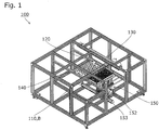
- the plant-transplanting device 100 includes the plant holder 110 in which a plurality of holder seedbed retaining parts 111 that pass through the plant holder 110 in the vertical direction and retain the seedbed B are disposed in a horizontal direction, the cultivation pallet 120 in which a plurality of pallet seedbed retaining parts 121 that pass through the cultivation pallet 120 in the vertical direction and retain the seedbed B are disposed in the horizontal direction, a holder retaining/moving mechanism 130 that retains the plant holder 110 and moves the plant holder 110 in the horizontal direction, a pallet retaining mechanism 140 that retains the cultivation pallet 120 in a fixed state, and a transferring mechanism 150 that transfers the seedbed B in the vertical direction.
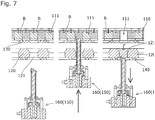
- the plant holder 110 is retained at a position above the cultivation pallet 120 by the holder retaining/moving mechanism 130 and the pallet retaining mechanism 140, the seedbed B retained by the holder seedbed retaining part 111 is lowered and inserted into the pallet seedbed retaining part 121 by the transferring mechanism 150, and the seedbed B is thereby transplanted.
- the plant-transplanting device 100 may also be configured such that the plant holder 110 is retained at a position below the cultivation pallet 120, the seedbed B retained by the holder seedbed retaining part 111 is raised and inserted into the pallet seedbed retaining part 121 by the transferring mechanism 150, and the seedbed B is thereby transplanted.
- the seedbed B in the present embodiment is formed of urethane or the like and is formed into a mat-like shape in which a plurality of seedbeds B1 each having a seed and seedling accommodating part B2 are coupled to each other longitudinally and laterally, as shown in Fig. 3 .
- Each seedbed B1 is partially coupled to the adjacent seedbed B1 at the central portion of each side of the seedbed B1 with a coupling part B3 that extends along a thickness direction of the seedbed B.
- the specific form of the seedbed B1 is not limited to the form described above, and the specific form thereof may be any form.
- the transferring mechanism 150 has a plurality of the seedbed holding units 160, a supporting part 151 that supports the plurality of the seedbed holding units 160, a lateral linear actuator 152 that moves the supporting part 151 in the lateral direction, and a longitudinal linear actuator 153 that moves the lateral linear actuator 152 in a longitudinal direction, adjusts the position of each seedbed holding unit 160 in the horizontal direction using the lateral linear actuator 152 and the longitudinal linear actuator 153, and transfers the seedbed B in the vertical direction in a state in which the seedbed B is held by the seedbed holding unit 160.
- each seedbed holding unit 160 includes a first holding member 170 and a second holding member 180 that are rotatable relative to each other about a predetermined rotation axis A, a base part 190 that supports the first holding member 170 and the second holding member 180, and an advance/retreat driving part 193 (shown in Fig. 2 ) that drives the base part 190 such that the base part 190 is able to advance or retreat along the vertical direction (rotation axis direction).
- the first holding member 170 is formed of a rigid material such as metal and, as shown in Fig. 4 to Fig. 6 , integrally includes a bar-shaped shaft part 171 that extends along the predetermined rotation axis A, a first claw supporting part 172 that is formed at the tip of the shaft part 171, two first claw parts 173 that are formed on the first claw supporting part 172, and a driven part 174 that is formed at the lower end of the shaft part 171 and engages with a rotational driving part 192 of the base part 190.
- the first claw supporting part 172 has an outer edge that is circular when it is viewed in the rotation axis direction, and the two first claw parts 173 are formed at positions that oppose each other with an angle of 180° on the outer edge of the first claw supporting part 172.
- the second holding member 180 is formed of a rigid material such as metal and, as shown in Fig. 4 to Fig. 6 , integrally includes a cylindrical pipe part 181 that extends along the rotation axis direction, a second claw supporting part 182 that is formed at the tip of the pipe part 181, two second claw parts 183 that are formed on the second claw supporting part 182, and a flange part 184 that is formed at the lower end of the pipe part 181 and fixed to the base part 190.
- the second claw supporting part 182 has an outer edge that is circular when it is viewed in the rotation axis direction, and the two second claw parts 183 are formed at positions that oppose each other with an angle of 180° on the outer edge of the second claw supporting part 182. As shown in Fig.
- the shaft part 171 of the first holding member 170 is inserted into the pipe part 181 of the second holding member 180.
- a sliding bearing member 194 is disposed between the first holding member 170 and the second holding member 180 but, in the case where the shaft part 171 and the pipe part 181 are configured so as to slide relative to each other adequately, the installation of the sliding bearing member 194 is not necessary.
- each of the first claw part 173 and the second claw part 183 is formed such that the tip side thereof is narrower than the bottom side thereof, and an uneven nonslip part is formed on a holding surface thereof.
- the base part 190 has a support stand 191 to which the second holding member 180 is fixed, and the rotational driving part 192 that is disposed so as to be fixed to the support stand 191.
- the rotational driving part 192 engages with the shaft part 171 of the second holding member 180 and rotationally drives the second holding member 180, and is configured as an air-driven actuator in the present embodiment.
- the specific form of the rotational driving part 192 may be any form as long as the rotational driving part causes the first holding member 170 and the second holding member 180 to rotate relative to each other, and the rotational driving part may be, e.g., an electric motor.
- the advance/retreat driving part 193 is configured as the air-driven actuator, and drives the base part 190 such that the base part 190 is able to advance or retreat along the vertical direction.
- the specific form of the advance/retreat driving part 193 may be any form as long as the advance/retreat driving part drives the base part 190 such that the base part 190 is able to advance or retreat along the rotation axis direction.
- the seedbed holding unit 160 configured as described above holds the seedbed B using the first claw parts 173 formed on the first holding member 170 and the second claw parts 183 formed on the second holding member 180 by rotating the first holding member 170 and the second holding member 180 relative to each other about the predetermined rotation axis A using the rotational driving part 192, and transfers the held seedbed B in the vertical direction by driving the base part 190 such that the base part 190 advances or retreats in the vertical direction using the advance/retreat driving part 193.
- a seedbed holding unit 260 according to a second embodiment of the present invention will be described based on Fig. 8 .
- the configurations other than that of the claw part formed in the holding member are the same as those in the first embodiment described above. Accordingly, the description of the configurations other than that of the claw part will be omitted by changing the leftmost digit of each reference sign shown in the description and the drawings related to the first embodiment from 1 to 2.
- first claw parts 273 are formed at intervals of 90° on an outer edge of a first claw supporting part 272 of a first holding member 270
- second claw parts 283 are formed at intervals of 90° on an outer edge of a second claw supporting part 282 of a second holding member 280.
- the first claw parts 173 and the second claw parts 183 are formed integrally with the first holding member 170 and the second holding member 180.
- the first claw parts 273 and the second claw parts 283 are formed separately from the first holding member 270 and the second holding member 280, and are fixed to the first claw supporting part 272 and the second claw supporting part 282.
- the claw parts 273 and 283 are formed separately from the holding members 270 and 280, it becomes possible to perform usage such as replacing the claw parts 273 and 283 when the claw parts 273 and 283 are damaged or changing the type of each of the claw parts 273 and 283 in accordance with the size and shape of the seedbed B.
- the description has been made on the assumption that the seedbed holding unit is used for the transplantation of the seedbed into the cultivation pallet from the plant holder, but the specific usage of the seedbed holding unit is not limited thereto, and the usage of the seedbed holding unit may be any usage as long as the usage requires holding of the seedbed.
- the description has been made on the assumption that two or four first claw parts and two or four second claw parts are provided, but the specific number of the first claw parts or the second claw parts only needs to be one or more.
- the seedbed holding unit may be configured such that the second holding member is also rotated when the seedbed is held.
Landscapes
- Life Sciences & Earth Sciences (AREA)
- Environmental Sciences (AREA)
- Engineering & Computer Science (AREA)
- Soil Sciences (AREA)
- Robotics (AREA)
- Mechanical Engineering (AREA)
- Botany (AREA)
- Hydroponics (AREA)
- Cultivation Receptacles Or Flower-Pots, Or Pots For Seedlings (AREA)
- Manipulator (AREA)
- Pretreatment Of Seeds And Plants (AREA)
- Cultivation Of Plants (AREA)
Abstract
Description
- The present invention relates to a seedbed holding unit that holds a seedbed used in plant cultivation, and more particularly to a seedbed holding unit that is used in plant transplantation.
- In the prior art, there is known an automatic planting device for a hydroponic seedling, which includes a seedbed transfer conveyor that transfers a seedbed by performing intermittent rotation and lateral reciprocation, a planting panel transfer conveyor that is provided below the seedbed transfer conveyor and transfers a planting panel by performing the intermittent rotation, several transfer opening/closing holders that are positioned above the front end part of the seedbed transfer conveyor, hold and separate several seedbed pieces positioned collectively in the front end row of the seedbed on the seedbed transfer conveyor, and transfer the seedbed pieces forward, several insertion opening/closing holders that are positioned in front of the several transfer opening/closing holders, hold and lower the seedbed pieces transferred by the transfer opening/closing holders, and plant the seedbed pieces by inserting same into holes of the planting panel on the planting panel transfer conveyor, and an operation mechanism that is coupled to the seedbed transfer conveyor and causes the seedbed transfer conveyor to intermittently reciprocate in a lateral direction by the width of the seedbed piece of the seedbed (see, e.g., Patent Literature 1).
- In the automatic planting device described in
Patent Literature 1, the opening/closing holder (the transfer opening/closing holder and the insertion opening/closing holder) configured to hold the seedbed using a pair of holding pieces capable of linearly moving closer to and away from each other is used as a seedbed holding unit that holds the seedbed. - Patent Literature 1:
Japanese Patent Application Laid-open No. 2000-4699 - The opening/closing holder described in
Patent Literature 1 requires a movement space S for the pair ofholding pieces Fig. 9 , in the case where the pair of theholding pieces hole 521 of a predetermined size and hold a seedbed B positioned beyond thehole 521, it is necessary for theholding pieces holding pieces holding pieces holding pieces - In addition, as in the opening/closing holder described in
Patent Literature 1, in the case where the seedbed B is held by the pair of theholding pieces Fig. 9 ) of the seedbed B that are spaced part in a direction X in which theholding pieces Fig. 9 . - The present invention has been devised to solve these problems, and an object thereof is to provide a seedbed holding unit capable of reliably and firmly holding the seedbed with a simple structure, causing no damage to a plant.
- The present invention is a seedbed holding unit that holds a seedbed used in plant cultivation, the seedbed holding unit including a first holding member and a second holding member that are rotatable relative to each other about a predetermined rotation axis, wherein the first holding member is provided with a first claw part in a fixed state, the second holding member is provided with a second claw part in the fixed state, and the seedbed is held between the first claw part and the second claw part by rotating the first holding member and the second holding member relative to each other, whereby the above problem is solved.
- According to a first aspect of the present invention, by configuring the seedbed holding unit such that the seedbed is held between the first claw part of the first holding member and the second claw part of the second holding member by rotating the first holding member and the second holding member relative to each other, unlike the conventional seedbed holding unit configured such that the seedbed is held between a pair of the holding pieces that are capable of moving closer to and away from each other, it is not necessary to secure the movement space for causing the first holding member and the second holding member to move closer to and away from each other in the lateral direction, and hence, even in the case where the holding member is caused to pass through a hole of a predetermined size, it is possible to secure the sufficient width of each holding member. With this, it is possible to secure the rigidity of each holding member, and reliably and firmly hold the seedbed without causing deformation in each holding member.
- In addition, by adopting the configuration in which the seedbed is held between the first claw part and the second claw part by moving the first claw part and the second claw part in a circumferential direction, unlike the conventional seedbed holding unit, limitations, such as the impossibility to separately hold each of a plurality of portions of the seedbed that are spaced apart in a direction in which the holding pieces move closer to and away from each other, are not posed, and hence flexibility in design related to the portion of the seedbed to be held is improved, and it is possible to reliably and stably hold the seedbed in accordance with the form of the seedbed.
- According to a second aspect of the present invention, by providing the first holding member with a plurality of the first claw parts in a fixed state and providing the second holding member with a plurality of the second claw parts in a fixed state, it is possible to reliably synchronize timings of holding by the plurality of the claw parts, and hence it is possible to hold a plurality of portions of the seedbed at the same time using the plurality of the claw parts and, in particular, even in the case where the outer edge of the seedbed is held instead of holding a portion near the center of the seedbed in order to avoid damage to a plant, it is possible to hold a plurality of portions in the outer edge of the seedbed so that it is possible to grasp the seedbed in a well-balanced manner.
- According to a third aspect of the present invention, the first claw part and the second claw part are provided on outer edge sides of a first claw supporting part and a second claw supporting part, whereby it is possible to hold a portion near the outer edge of the seedbed using the claw parts instead of the portion near the center of the seedbed in which seeds and roots of the plant are retained, and hence it is possible to firmly hold the seedbed without damaging the plant retained in the seedbed.
- According to a fourth aspect of the present invention, the second holding member has a pipe part, and the first holding member has a shaft part that extends along the rotation axis and is inserted into the pipe part, whereby it is possible to bear the shaft part of the first holding member using the pipe part of the second holding member, and hence a necessity to additionally provide a bearing member is eliminated, the occurrence of a trouble is prevented by simplifying the structure, and it is possible to achieve a reduction in the size of each of the first holding member and the second holding member. In addition, by disposing the shaft part of the first holding member inside the pipe part of the second holding member, it is possible to prevent an increase in size in the lateral direction even in the case where the rigidity of each of the pipe part and the shaft part is secured.
- According to a fifth aspect of the present invention, by fixing the second holding member having the pipe part to a base part and rotationally driving the first holding member having the shaft part disposed in the pipe part, it is possible to prevent the rotationally driven shaft part from being exposed to the outside to secure the safety of a user, and the design of a peripheral environment is facilitated.
- According to a sixth aspect of the present invention, by driving the base part using an advance/retreat driving part such that the base part is able to advance or retreat along the rotation axis direction, it is possible to insert or pull out the seedbed into or from a seedbed retaining part formed in a container or the like in a state in which the seedbed is held by the claw parts, and hence it is possible to stably and smoothly perform a transplantation operation of the seedbed.
-
- [
Fig. 1] Fig. 1 is a perspective view showing a plant-transplanting device into which a seedbed holding unit as a first embodiment of the present invention is incorporated. - [
Fig. 2] Fig. 2 is a front view showing the plant-transplanting device. - [
Fig. 3] Fig. 3 is an explanatory view showing a seedbed. - [
Fig. 4] Fig. 4 is an explanatory view showing the seedbed holding unit in a state in which claw parts are spaced apart. - [
Fig. 5] Fig. 5 is an explanatory view showing the seedbed holding unit in a state in which the claw parts are in contact with each other. - [
Fig. 6] Fig. 6 is a cross-sectional view showing the seedbed holding unit. - [
Fig. 7] Fig. 7 is an explanatory view showing a seedbed transplanting flow. - [
Fig. 8] Fig. 8 is an explanatory view showing a seedbed holding unit as a second embodiment of the present invention. - [
Fig. 9] Fig. 9 is an explanatory view showing a seedbed holding unit as Reference Example. -
- 100
- Plant-transplanting device
- 110
- Plant holder
- 120
- Cultivation pallet
- 130
- Holder retaining/moving mechanism
- 140
- Pallet retaining mechanism
- 150
- Transferring mechanism
- 151
- Supporting part
- 152
- Lateral linear actuator
- 153
- Longitudinal linear actuator
- 160, 260
- Seedbed holding unit
- 170, 270
- First holding member
- 171
- Shaft part
- 172, 272
- First claw supporting part
- 173, 273
- First claw part
- 174
- Driven part
- 180, 280
- Second holding member
- 181, 281
- Pipe part
- 182, 282
- Second claw supporting part
- 183, 283
- Second claw part
- 184, 284
- Flange part
- 190, 290
- Base part
- 191, 291
- Support stand
- 192, 292
- Rotational driving part
- 193
- Advance/retreat driving part
- 194
- Sliding bearing member
- B
- Seedbed
- Hereinbelow, a
seedbed holding unit 160 as a first embodiment of the present invention will be described based on the drawings. - First, it should be noted that the
seedbed holding unit 160 is used by being incorporated into a plant-transplantingdevice 100 that transplants a seedbed B from aplant holder 110 to acultivation pallet 120. Specifically, theseedbed holding unit 160 is incorporated into atransferring mechanism 150 of the plant-transplantingdevice 100, and transfers the seedbed B in a vertical direction while holding the seedbed B during the transfer of the seedbed B in the vertical direction. - As shown in
Fig. 1 , the plant-transplantingdevice 100 includes theplant holder 110 in which a plurality of holderseedbed retaining parts 111 that pass through theplant holder 110 in the vertical direction and retain the seedbed B are disposed in a horizontal direction, thecultivation pallet 120 in which a plurality of palletseedbed retaining parts 121 that pass through thecultivation pallet 120 in the vertical direction and retain the seedbed B are disposed in the horizontal direction, a holder retaining/movingmechanism 130 that retains theplant holder 110 and moves theplant holder 110 in the horizontal direction, apallet retaining mechanism 140 that retains thecultivation pallet 120 in a fixed state, and atransferring mechanism 150 that transfers the seedbed B in the vertical direction. - As shown in
Fig. 7 , in the plant-transplantingdevice 100 of the present embodiment, theplant holder 110 is retained at a position above thecultivation pallet 120 by the holder retaining/movingmechanism 130 and thepallet retaining mechanism 140, the seedbed B retained by the holderseedbed retaining part 111 is lowered and inserted into the palletseedbed retaining part 121 by thetransferring mechanism 150, and the seedbed B is thereby transplanted. - Note that, conversely, the plant-transplanting
device 100 may also be configured such that theplant holder 110 is retained at a position below thecultivation pallet 120, the seedbed B retained by the holderseedbed retaining part 111 is raised and inserted into the palletseedbed retaining part 121 by thetransferring mechanism 150, and the seedbed B is thereby transplanted. - The seedbed B in the present embodiment is formed of urethane or the like and is formed into a mat-like shape in which a plurality of seedbeds B1 each having a seed and seedling accommodating part B2 are coupled to each other longitudinally and laterally, as shown in
Fig. 3 . Each seedbed B1 is partially coupled to the adjacent seedbed B1 at the central portion of each side of the seedbed B1 with a coupling part B3 that extends along a thickness direction of the seedbed B. Note that the specific form of the seedbed B1 is not limited to the form described above, and the specific form thereof may be any form. - Next, the
transferring mechanism 150 into which theseedbed holding unit 160 of the present embodiment is incorporated will be described based on the drawings. - As shown in
Fig. 1 andFig. 2 , thetransferring mechanism 150 has a plurality of theseedbed holding units 160, a supportingpart 151 that supports the plurality of theseedbed holding units 160, a laterallinear actuator 152 that moves the supportingpart 151 in the lateral direction, and a longitudinallinear actuator 153 that moves the laterallinear actuator 152 in a longitudinal direction, adjusts the position of eachseedbed holding unit 160 in the horizontal direction using the laterallinear actuator 152 and the longitudinallinear actuator 153, and transfers the seedbed B in the vertical direction in a state in which the seedbed B is held by theseedbed holding unit 160. - As shown in
Fig. 4 to Fig. 6 , eachseedbed holding unit 160 includes a first holdingmember 170 and asecond holding member 180 that are rotatable relative to each other about a predetermined rotation axis A, abase part 190 that supports the first holdingmember 170 and the second holdingmember 180, and an advance/retreat driving part 193 (shown inFig. 2 ) that drives thebase part 190 such that thebase part 190 is able to advance or retreat along the vertical direction (rotation axis direction). - The
first holding member 170 is formed of a rigid material such as metal and, as shown inFig. 4 to Fig. 6 , integrally includes a bar-shapedshaft part 171 that extends along the predetermined rotation axis A, a firstclaw supporting part 172 that is formed at the tip of theshaft part 171, twofirst claw parts 173 that are formed on the firstclaw supporting part 172, and adriven part 174 that is formed at the lower end of theshaft part 171 and engages with arotational driving part 192 of thebase part 190. The firstclaw supporting part 172 has an outer edge that is circular when it is viewed in the rotation axis direction, and the twofirst claw parts 173 are formed at positions that oppose each other with an angle of 180° on the outer edge of the firstclaw supporting part 172. - The
second holding member 180 is formed of a rigid material such as metal and, as shown inFig. 4 to Fig. 6 , integrally includes acylindrical pipe part 181 that extends along the rotation axis direction, a secondclaw supporting part 182 that is formed at the tip of thepipe part 181, twosecond claw parts 183 that are formed on the secondclaw supporting part 182, and aflange part 184 that is formed at the lower end of thepipe part 181 and fixed to thebase part 190. The secondclaw supporting part 182 has an outer edge that is circular when it is viewed in the rotation axis direction, and the twosecond claw parts 183 are formed at positions that oppose each other with an angle of 180° on the outer edge of the secondclaw supporting part 182. As shown inFig. 6 , theshaft part 171 of the first holdingmember 170 is inserted into thepipe part 181 of the second holdingmember 180. Note that, in the present embodiment, as shown inFig. 6 , a slidingbearing member 194 is disposed between the first holdingmember 170 and the second holdingmember 180 but, in the case where theshaft part 171 and thepipe part 181 are configured so as to slide relative to each other adequately, the installation of the slidingbearing member 194 is not necessary. - As shown in
Fig. 4 andFig. 5 , each of thefirst claw part 173 and thesecond claw part 183 is formed such that the tip side thereof is narrower than the bottom side thereof, and an uneven nonslip part is formed on a holding surface thereof. - As shown in
Fig. 4 to Fig. 6 , thebase part 190 has asupport stand 191 to which the second holdingmember 180 is fixed, and therotational driving part 192 that is disposed so as to be fixed to thesupport stand 191. Therotational driving part 192 engages with theshaft part 171 of the second holdingmember 180 and rotationally drives the second holdingmember 180, and is configured as an air-driven actuator in the present embodiment. Note that the specific form of therotational driving part 192 may be any form as long as the rotational driving part causes the first holdingmember 170 and the second holdingmember 180 to rotate relative to each other, and the rotational driving part may be, e.g., an electric motor. - The advance/
retreat driving part 193 is configured as the air-driven actuator, and drives thebase part 190 such that thebase part 190 is able to advance or retreat along the vertical direction. Note that the specific form of the advance/retreat driving part 193 may be any form as long as the advance/retreat driving part drives thebase part 190 such that thebase part 190 is able to advance or retreat along the rotation axis direction. - The
seedbed holding unit 160 configured as described above holds the seedbed B using thefirst claw parts 173 formed on the first holdingmember 170 and thesecond claw parts 183 formed on the second holdingmember 180 by rotating the first holdingmember 170 and the second holdingmember 180 relative to each other about the predetermined rotation axis A using therotational driving part 192, and transfers the held seedbed B in the vertical direction by driving thebase part 190 such that thebase part 190 advances or retreats in the vertical direction using the advance/retreat driving part 193. - Next, a
seedbed holding unit 260 according to a second embodiment of the present invention will be described based onFig. 8 . Herein, in the second embodiment, the configurations other than that of the claw part formed in the holding member are the same as those in the first embodiment described above. Accordingly, the description of the configurations other than that of the claw part will be omitted by changing the leftmost digit of each reference sign shown in the description and the drawings related to the first embodiment from 1 to 2. - In the second embodiment, as shown in
Fig. 8 , fourfirst claw parts 273 are formed at intervals of 90° on an outer edge of a firstclaw supporting part 272 of a first holdingmember 270, and foursecond claw parts 283 are formed at intervals of 90° on an outer edge of a secondclaw supporting part 282 of asecond holding member 280. - In addition, in the first embodiment, the
first claw parts 173 and thesecond claw parts 183 are formed integrally with the first holdingmember 170 and the second holdingmember 180. On the other hand, in the second embodiment, as shown inFig. 8 , thefirst claw parts 273 and thesecond claw parts 283 are formed separately from the first holdingmember 270 and the second holdingmember 280, and are fixed to the firstclaw supporting part 272 and the secondclaw supporting part 282. Thus, in the case where theclaw parts members claw parts claw parts claw parts - Thus, the embodiments of the present invention have been described, but the present invention is not limited to the above embodiments, and various design changes can be made without departing from the present invention described in the claims.
- For example, in the embodiments described above, the description has been made on the assumption that the seedbed holding unit is used for the transplantation of the seedbed into the cultivation pallet from the plant holder, but the specific usage of the seedbed holding unit is not limited thereto, and the usage of the seedbed holding unit may be any usage as long as the usage requires holding of the seedbed.
- In addition, in the embodiments described above, the description has been made on the assumption that two or four first claw parts and two or four second claw parts are provided, but the specific number of the first claw parts or the second claw parts only needs to be one or more. In the case where a plurality of the first claw parts and a plurality of the second claw parts are provided, it is preferable to dispose the claw parts at regular angle intervals on the outer edge of the claw supporting part of each holding member.
- Further, in the embodiments described above, the description has been made on the assumption that the seedbed is held by the first claw part and the second claw part by fixing the second holding member and rotating the first holding member, but the seedbed holding unit may be configured such that the second holding member is also rotated when the seedbed is held.
Claims (6)
- A seedbed holding unit that holds a seedbed used in plant cultivation, the seedbed holding unit comprising:a first holding member and a second holding member that are rotatable relative to each other about a predetermined rotation axis, whereinthe first holding member is provided with a first claw part in a fixed state,the second holding member is provided with a second claw part in a fixed state, andthe seedbed is held between the first claw part and the second claw part by rotating the first holding member and the second holding member relative to each other.
- The seedbed holding unit according to claim 1, wherein
the first holding member is provided with a plurality of the first claw parts in a fixed state, and
the second holding member is provided with a plurality of the second claw parts in a fixed state. - The seedbed holding unit according to claim 1 or 2, wherein
the first holding member has a first claw supporting part that supports the first claw part on a tip side thereof,
the second holding member has a second claw supporting part that supports the second claw part on a tip side thereof,
the first claw supporting part and the second claw supporting part respectively have an outer edge that is circular when viewed in a rotation axis direction, and
the first claw part and the second claw part are respectively provided on respective outer edge sides of the first claw supporting part and the second claw supporting part. - The seedbed holding unit according to any one of claims 1 to 3, wherein
the second holding member has a pipe part, and
the first holding member has a shaft part that extends along the rotation axis and is inserted into the pipe part. - The seedbed holding unit according to claim 4, further comprising:a base part that supports the pipe part of the second holding member in a fixed state, whereina rotational driving part that rotationally drives the shaft part of the first holding member is disposed in the base part.
- The seedbed holding unit according to claim 5, further comprising:an advance/retreat driving part that drives the base part such that the base part is able to advance or retreat along the rotation axis direction.
Applications Claiming Priority (2)
| Application Number | Priority Date | Filing Date | Title |
|---|---|---|---|
| JP2014131625A JP6122811B2 (en) | 2014-06-26 | 2014-06-26 | Nursery bed holding unit |
| PCT/JP2015/058029 WO2015198654A1 (en) | 2014-06-26 | 2015-03-18 | Seedbed holding unit |
Publications (3)
| Publication Number | Publication Date |
|---|---|
| EP3162517A1 true EP3162517A1 (en) | 2017-05-03 |
| EP3162517A4 EP3162517A4 (en) | 2018-02-21 |
| EP3162517B1 EP3162517B1 (en) | 2020-04-22 |
Family
ID=54937757
Family Applications (1)
| Application Number | Title | Priority Date | Filing Date |
|---|---|---|---|
| EP15811647.5A Not-in-force EP3162517B1 (en) | 2014-06-26 | 2015-03-18 | Seedbed holding unit |
Country Status (5)
| Country | Link |
|---|---|
| US (1) | US10136586B2 (en) |
| EP (1) | EP3162517B1 (en) |
| JP (1) | JP6122811B2 (en) |
| CN (1) | CN106457578B (en) |
| WO (1) | WO2015198654A1 (en) |
Families Citing this family (5)
| Publication number | Priority date | Publication date | Assignee | Title |
|---|---|---|---|---|
| JP2019014003A (en) * | 2017-07-05 | 2019-01-31 | 川崎重工業株式会社 | Robot system and packaging system |
| WO2019064448A1 (en) * | 2017-09-28 | 2019-04-04 | 株式会社Fuji | TOOL FOR PREPARING A PART |
| JP6865472B2 (en) * | 2018-10-09 | 2021-04-28 | 株式会社大橋製作所 | Gripping device and splitting device, and transplanting device and transplanting system using them |
| CN110809964A (en) * | 2019-11-29 | 2020-02-21 | 澧县绿之源生态农业科技发展有限公司 | Equipment is planted to multiple-connected type green pepper seedling |
| CN115486242A (en) * | 2022-08-23 | 2022-12-20 | 苏州新农益科技有限公司 | Soilless Crop Transplanting Equipment |
Family Cites Families (13)
| Publication number | Priority date | Publication date | Assignee | Title |
|---|---|---|---|---|
| DE1782516A1 (en) * | 1968-09-12 | 1971-09-16 | Stahl Und Appbau Mayer Kg | Adjustable holder for soil containers in potting and repotting machines |
| NL8004362A (en) * | 1979-08-03 | 1981-02-05 | Nat Res Dev | APPARATUS FOR HANDLING BREEDING OR GROWING POTS OR BLOCKS. |
| US5247761A (en) * | 1991-01-03 | 1993-09-28 | Robotic Solutions, Inc. | Computer controlled seedling transfer apparatus |
| JP3598446B2 (en) * | 1995-12-29 | 2004-12-08 | 有限会社ティアンドティナーサリー | Cell seedling transplanter |
| JP3940815B2 (en) * | 1998-04-20 | 2007-07-04 | 有限会社ティアンドティナーサリー | Cell seedling transplanter |
| JP2938044B1 (en) * | 1998-06-23 | 1999-08-23 | 株式会社キタムラ | Method and apparatus for automatic planting of hydroponic seedlings |
| JP2000060316A (en) * | 1998-08-20 | 2000-02-29 | Yanmar Agricult Equip Co Ltd | Potting equipment |
| JP2000175511A (en) * | 1998-12-15 | 2000-06-27 | Honda Motor Co Ltd | Nursery sheet and seedling transplanter |
| US6338512B1 (en) * | 2000-01-31 | 2002-01-15 | Jonathan Paul Ruppert | Clamp action shovel for single hand operation |
| JP2004187540A (en) * | 2002-12-10 | 2004-07-08 | Teruyuki Kai | Nursery seed growing method and nursery transplanter |
| US6966269B2 (en) * | 2002-12-18 | 2005-11-22 | Brian Sawatzky | Multi-purpose garden tool |
| US20090132086A1 (en) * | 2007-11-16 | 2009-05-21 | Fanuc Ltd | Holding apparatus and holding unit |
| CN201491562U (en) * | 2009-09-25 | 2010-06-02 | 沈阳农业大学 | An automatic transplanting machine for plug seedlings |
-
2014
- 2014-06-26 JP JP2014131625A patent/JP6122811B2/en active Active
-
2015
- 2015-03-18 WO PCT/JP2015/058029 patent/WO2015198654A1/en not_active Ceased
- 2015-03-18 CN CN201580032210.1A patent/CN106457578B/en not_active Expired - Fee Related
- 2015-03-18 EP EP15811647.5A patent/EP3162517B1/en not_active Not-in-force
-
2016
- 2016-12-22 US US15/388,057 patent/US10136586B2/en not_active Expired - Fee Related
Also Published As
| Publication number | Publication date |
|---|---|
| JP2016007686A (en) | 2016-01-18 |
| JP6122811B2 (en) | 2017-04-26 |
| US10136586B2 (en) | 2018-11-27 |
| CN106457578B (en) | 2018-12-07 |
| EP3162517B1 (en) | 2020-04-22 |
| EP3162517A4 (en) | 2018-02-21 |
| CN106457578A (en) | 2017-02-22 |
| US20170099784A1 (en) | 2017-04-13 |
| WO2015198654A1 (en) | 2015-12-30 |
Similar Documents
| Publication | Publication Date | Title |
|---|---|---|
| US10136586B2 (en) | Seedbed holding unit | |
| US20170099783A1 (en) | Plant-transplanting device | |
| US10058024B2 (en) | Plant transplanting device | |
| EP2868191B1 (en) | Transplanting device and transplanting method | |
| JP6200374B2 (en) | Plant transplanting equipment | |
| JP6598088B2 (en) | Plant cultivation system and plant cultivation method | |
| EP3135428A1 (en) | Tool magazine and tool exchange device | |
| JP5290741B2 (en) | Seedling transplanter | |
| KR102527393B1 (en) | Automatic hair implanter | |
| FR3052333A1 (en) | INSTALLATION FOR GROUND CULTIVATION. | |
| KR20080083435A (en) | Sowing body device using sowing unit of sowing machine | |
| ES2784392T3 (en) | Drive device to be installed on a drive shaft | |
| CN105766157A (en) | Seed obtaining disc for seed-metering device and seed-metering device with same | |
| JP2015078147A (en) | Holder for sealed container for cryopreservation | |
| ES2326736T3 (en) | PLANTULA TRANSPLANTING MACHINE WITH ROTARY DISTRIBUTOR TO PLANT PLANTULAS DISPOSING THEM IN TWO ROWS. | |
| JP7405396B2 (en) | transplant device | |
| CN112167043B (en) | Plant holder and plant cultivation system | |
| JP2019080529A (en) | Plant cultivation equipment | |
| CN115885642B (en) | A disc-clamp type sweet potato transplanter and transplanting method | |
| CN110326411B (en) | Green onion conveying mechanism and transplanting machine | |
| JP6723599B2 (en) | Scraping fork structure of feeding roll of seeding machine for nursery box | |
| JP7008947B2 (en) | Plant holder | |
| JP2022020822A (en) | Plant cultivation system | |
| JP6275604B2 (en) | Mobile cultivation equipment | |
| KR200367475Y1 (en) | Saplings carrying frame with transfer device |
Legal Events
| Date | Code | Title | Description |
|---|---|---|---|
| STAA | Information on the status of an ep patent application or granted ep patent |
Free format text: STATUS: THE INTERNATIONAL PUBLICATION HAS BEEN MADE |
|
| PUAI | Public reference made under article 153(3) epc to a published international application that has entered the european phase |
Free format text: ORIGINAL CODE: 0009012 |
|
| STAA | Information on the status of an ep patent application or granted ep patent |
Free format text: STATUS: REQUEST FOR EXAMINATION WAS MADE |
|
| 17P | Request for examination filed |
Effective date: 20170117 |
|
| AK | Designated contracting states |
Kind code of ref document: A1 Designated state(s): AL AT BE BG CH CY CZ DE DK EE ES FI FR GB GR HR HU IE IS IT LI LT LU LV MC MK MT NL NO PL PT RO RS SE SI SK SM TR |
|
| AX | Request for extension of the european patent |
Extension state: BA ME |
|
| DAV | Request for validation of the european patent (deleted) | ||
| DAX | Request for extension of the european patent (deleted) | ||
| A4 | Supplementary search report drawn up and despatched |
Effective date: 20180123 |
|
| RIC1 | Information provided on ipc code assigned before grant |
Ipc: B25J 15/08 20060101AFI20180117BHEP Ipc: A01G 9/08 20060101ALI20180117BHEP |
|
| RIN1 | Information on inventor provided before grant (corrected) |
Inventor name: ITO, GO Inventor name: TSUTSUMI, KAZUHIRO |
|
| REG | Reference to a national code |
Ref country code: DE Ref legal event code: R079 Ref document number: 602015051294 Country of ref document: DE Free format text: PREVIOUS MAIN CLASS: B25J0015080000 Ipc: A01G0009029000 |
|
| GRAP | Despatch of communication of intention to grant a patent |
Free format text: ORIGINAL CODE: EPIDOSNIGR1 |
|
| STAA | Information on the status of an ep patent application or granted ep patent |
Free format text: STATUS: GRANT OF PATENT IS INTENDED |
|
| RIC1 | Information provided on ipc code assigned before grant |
Ipc: A01G 9/029 20180101AFI20191101BHEP |
|
| INTG | Intention to grant announced |
Effective date: 20191202 |
|
| GRAS | Grant fee paid |
Free format text: ORIGINAL CODE: EPIDOSNIGR3 |
|
| GRAA | (expected) grant |
Free format text: ORIGINAL CODE: 0009210 |
|
| STAA | Information on the status of an ep patent application or granted ep patent |
Free format text: STATUS: THE PATENT HAS BEEN GRANTED |
|
| AK | Designated contracting states |
Kind code of ref document: B1 Designated state(s): AL AT BE BG CH CY CZ DE DK EE ES FI FR GB GR HR HU IE IS IT LI LT LU LV MC MK MT NL NO PL PT RO RS SE SI SK SM TR |
|
| REG | Reference to a national code |
Ref country code: CH Ref legal event code: EP |
|
| REG | Reference to a national code |
Ref country code: DE Ref legal event code: R096 Ref document number: 602015051294 Country of ref document: DE |
|
| REG | Reference to a national code |
Ref country code: IE Ref legal event code: FG4D |
|
| REG | Reference to a national code |
Ref country code: AT Ref legal event code: REF Ref document number: 1258838 Country of ref document: AT Kind code of ref document: T Effective date: 20200515 |
|
| REG | Reference to a national code |
Ref country code: NL Ref legal event code: FP |
|
| REG | Reference to a national code |
Ref country code: LT Ref legal event code: MG4D |
|
| PG25 | Lapsed in a contracting state [announced via postgrant information from national office to epo] |
Ref country code: GR Free format text: LAPSE BECAUSE OF FAILURE TO SUBMIT A TRANSLATION OF THE DESCRIPTION OR TO PAY THE FEE WITHIN THE PRESCRIBED TIME-LIMIT Effective date: 20200723 Ref country code: NO Free format text: LAPSE BECAUSE OF FAILURE TO SUBMIT A TRANSLATION OF THE DESCRIPTION OR TO PAY THE FEE WITHIN THE PRESCRIBED TIME-LIMIT Effective date: 20200722 Ref country code: FI Free format text: LAPSE BECAUSE OF FAILURE TO SUBMIT A TRANSLATION OF THE DESCRIPTION OR TO PAY THE FEE WITHIN THE PRESCRIBED TIME-LIMIT Effective date: 20200422 Ref country code: LT Free format text: LAPSE BECAUSE OF FAILURE TO SUBMIT A TRANSLATION OF THE DESCRIPTION OR TO PAY THE FEE WITHIN THE PRESCRIBED TIME-LIMIT Effective date: 20200422 Ref country code: SE Free format text: LAPSE BECAUSE OF FAILURE TO SUBMIT A TRANSLATION OF THE DESCRIPTION OR TO PAY THE FEE WITHIN THE PRESCRIBED TIME-LIMIT Effective date: 20200422 Ref country code: IS Free format text: LAPSE BECAUSE OF FAILURE TO SUBMIT A TRANSLATION OF THE DESCRIPTION OR TO PAY THE FEE WITHIN THE PRESCRIBED TIME-LIMIT Effective date: 20200822 Ref country code: PT Free format text: LAPSE BECAUSE OF FAILURE TO SUBMIT A TRANSLATION OF THE DESCRIPTION OR TO PAY THE FEE WITHIN THE PRESCRIBED TIME-LIMIT Effective date: 20200824 |
|
| REG | Reference to a national code |
Ref country code: AT Ref legal event code: MK05 Ref document number: 1258838 Country of ref document: AT Kind code of ref document: T Effective date: 20200422 |
|
| PG25 | Lapsed in a contracting state [announced via postgrant information from national office to epo] |
Ref country code: RS Free format text: LAPSE BECAUSE OF FAILURE TO SUBMIT A TRANSLATION OF THE DESCRIPTION OR TO PAY THE FEE WITHIN THE PRESCRIBED TIME-LIMIT Effective date: 20200422 Ref country code: BG Free format text: LAPSE BECAUSE OF FAILURE TO SUBMIT A TRANSLATION OF THE DESCRIPTION OR TO PAY THE FEE WITHIN THE PRESCRIBED TIME-LIMIT Effective date: 20200722 Ref country code: LV Free format text: LAPSE BECAUSE OF FAILURE TO SUBMIT A TRANSLATION OF THE DESCRIPTION OR TO PAY THE FEE WITHIN THE PRESCRIBED TIME-LIMIT Effective date: 20200422 Ref country code: HR Free format text: LAPSE BECAUSE OF FAILURE TO SUBMIT A TRANSLATION OF THE DESCRIPTION OR TO PAY THE FEE WITHIN THE PRESCRIBED TIME-LIMIT Effective date: 20200422 |
|
| PG25 | Lapsed in a contracting state [announced via postgrant information from national office to epo] |
Ref country code: AL Free format text: LAPSE BECAUSE OF FAILURE TO SUBMIT A TRANSLATION OF THE DESCRIPTION OR TO PAY THE FEE WITHIN THE PRESCRIBED TIME-LIMIT Effective date: 20200422 |
|
| REG | Reference to a national code |
Ref country code: DE Ref legal event code: R097 Ref document number: 602015051294 Country of ref document: DE |
|
| PG25 | Lapsed in a contracting state [announced via postgrant information from national office to epo] |
Ref country code: ES Free format text: LAPSE BECAUSE OF FAILURE TO SUBMIT A TRANSLATION OF THE DESCRIPTION OR TO PAY THE FEE WITHIN THE PRESCRIBED TIME-LIMIT Effective date: 20200422 Ref country code: DK Free format text: LAPSE BECAUSE OF FAILURE TO SUBMIT A TRANSLATION OF THE DESCRIPTION OR TO PAY THE FEE WITHIN THE PRESCRIBED TIME-LIMIT Effective date: 20200422 Ref country code: SM Free format text: LAPSE BECAUSE OF FAILURE TO SUBMIT A TRANSLATION OF THE DESCRIPTION OR TO PAY THE FEE WITHIN THE PRESCRIBED TIME-LIMIT Effective date: 20200422 Ref country code: EE Free format text: LAPSE BECAUSE OF FAILURE TO SUBMIT A TRANSLATION OF THE DESCRIPTION OR TO PAY THE FEE WITHIN THE PRESCRIBED TIME-LIMIT Effective date: 20200422 Ref country code: IT Free format text: LAPSE BECAUSE OF FAILURE TO SUBMIT A TRANSLATION OF THE DESCRIPTION OR TO PAY THE FEE WITHIN THE PRESCRIBED TIME-LIMIT Effective date: 20200422 Ref country code: CZ Free format text: LAPSE BECAUSE OF FAILURE TO SUBMIT A TRANSLATION OF THE DESCRIPTION OR TO PAY THE FEE WITHIN THE PRESCRIBED TIME-LIMIT Effective date: 20200422 Ref country code: AT Free format text: LAPSE BECAUSE OF FAILURE TO SUBMIT A TRANSLATION OF THE DESCRIPTION OR TO PAY THE FEE WITHIN THE PRESCRIBED TIME-LIMIT Effective date: 20200422 Ref country code: RO Free format text: LAPSE BECAUSE OF FAILURE TO SUBMIT A TRANSLATION OF THE DESCRIPTION OR TO PAY THE FEE WITHIN THE PRESCRIBED TIME-LIMIT Effective date: 20200422 |
|
| PG25 | Lapsed in a contracting state [announced via postgrant information from national office to epo] |
Ref country code: PL Free format text: LAPSE BECAUSE OF FAILURE TO SUBMIT A TRANSLATION OF THE DESCRIPTION OR TO PAY THE FEE WITHIN THE PRESCRIBED TIME-LIMIT Effective date: 20200422 Ref country code: SK Free format text: LAPSE BECAUSE OF FAILURE TO SUBMIT A TRANSLATION OF THE DESCRIPTION OR TO PAY THE FEE WITHIN THE PRESCRIBED TIME-LIMIT Effective date: 20200422 |
|
| PLBE | No opposition filed within time limit |
Free format text: ORIGINAL CODE: 0009261 |
|
| STAA | Information on the status of an ep patent application or granted ep patent |
Free format text: STATUS: NO OPPOSITION FILED WITHIN TIME LIMIT |
|
| 26N | No opposition filed |
Effective date: 20210125 |
|
| PGFP | Annual fee paid to national office [announced via postgrant information from national office to epo] |
Ref country code: NL Payment date: 20210212 Year of fee payment: 7 |
|
| PG25 | Lapsed in a contracting state [announced via postgrant information from national office to epo] |
Ref country code: SI Free format text: LAPSE BECAUSE OF FAILURE TO SUBMIT A TRANSLATION OF THE DESCRIPTION OR TO PAY THE FEE WITHIN THE PRESCRIBED TIME-LIMIT Effective date: 20200422 |
|
| REG | Reference to a national code |
Ref country code: DE Ref legal event code: R119 Ref document number: 602015051294 Country of ref document: DE |
|
| PG25 | Lapsed in a contracting state [announced via postgrant information from national office to epo] |
Ref country code: MC Free format text: LAPSE BECAUSE OF FAILURE TO SUBMIT A TRANSLATION OF THE DESCRIPTION OR TO PAY THE FEE WITHIN THE PRESCRIBED TIME-LIMIT Effective date: 20200422 |
|
| REG | Reference to a national code |
Ref country code: CH Ref legal event code: PL |
|
| GBPC | Gb: european patent ceased through non-payment of renewal fee |
Effective date: 20210318 |
|
| REG | Reference to a national code |
Ref country code: BE Ref legal event code: MM Effective date: 20210331 |
|
| PG25 | Lapsed in a contracting state [announced via postgrant information from national office to epo] |
Ref country code: CH Free format text: LAPSE BECAUSE OF NON-PAYMENT OF DUE FEES Effective date: 20210331 Ref country code: LU Free format text: LAPSE BECAUSE OF NON-PAYMENT OF DUE FEES Effective date: 20210318 Ref country code: LI Free format text: LAPSE BECAUSE OF NON-PAYMENT OF DUE FEES Effective date: 20210331 Ref country code: GB Free format text: LAPSE BECAUSE OF NON-PAYMENT OF DUE FEES Effective date: 20210318 Ref country code: IE Free format text: LAPSE BECAUSE OF NON-PAYMENT OF DUE FEES Effective date: 20210318 Ref country code: FR Free format text: LAPSE BECAUSE OF NON-PAYMENT OF DUE FEES Effective date: 20210331 Ref country code: DE Free format text: LAPSE BECAUSE OF NON-PAYMENT OF DUE FEES Effective date: 20211001 |
|
| PG25 | Lapsed in a contracting state [announced via postgrant information from national office to epo] |
Ref country code: BE Free format text: LAPSE BECAUSE OF NON-PAYMENT OF DUE FEES Effective date: 20210331 |
|
| REG | Reference to a national code |
Ref country code: NL Ref legal event code: MM Effective date: 20220401 |
|
| PG25 | Lapsed in a contracting state [announced via postgrant information from national office to epo] |
Ref country code: NL Free format text: LAPSE BECAUSE OF NON-PAYMENT OF DUE FEES Effective date: 20220401 |
|
| PG25 | Lapsed in a contracting state [announced via postgrant information from national office to epo] |
Ref country code: HU Free format text: LAPSE BECAUSE OF FAILURE TO SUBMIT A TRANSLATION OF THE DESCRIPTION OR TO PAY THE FEE WITHIN THE PRESCRIBED TIME-LIMIT; INVALID AB INITIO Effective date: 20150318 |
|
| PG25 | Lapsed in a contracting state [announced via postgrant information from national office to epo] |
Ref country code: CY Free format text: LAPSE BECAUSE OF FAILURE TO SUBMIT A TRANSLATION OF THE DESCRIPTION OR TO PAY THE FEE WITHIN THE PRESCRIBED TIME-LIMIT Effective date: 20200422 |
|
| PG25 | Lapsed in a contracting state [announced via postgrant information from national office to epo] |
Ref country code: MK Free format text: LAPSE BECAUSE OF FAILURE TO SUBMIT A TRANSLATION OF THE DESCRIPTION OR TO PAY THE FEE WITHIN THE PRESCRIBED TIME-LIMIT Effective date: 20200422 |
|
| PG25 | Lapsed in a contracting state [announced via postgrant information from national office to epo] |
Ref country code: MT Free format text: LAPSE BECAUSE OF FAILURE TO SUBMIT A TRANSLATION OF THE DESCRIPTION OR TO PAY THE FEE WITHIN THE PRESCRIBED TIME-LIMIT Effective date: 20200422 |
|
| PG25 | Lapsed in a contracting state [announced via postgrant information from national office to epo] |
Ref country code: TR Free format text: LAPSE BECAUSE OF FAILURE TO SUBMIT A TRANSLATION OF THE DESCRIPTION OR TO PAY THE FEE WITHIN THE PRESCRIBED TIME-LIMIT Effective date: 20200422 |